

Page 1
Page 2

For use with Software Version 4.08.375
Image Server MAXX
August 2009
Copyright 2009, 360 Systems
All rights reserved
Printed in the United States of America
100-145-0018-01 MAXX UM
Page 2 MAXX Owner’s Manual
Page 3

Contents
™
Preface _______________________________________________________________ 8
Software and Operations Manual Revisions ................................ 8
Safety Notices _________________________________________________________ 9
Safety Terms and Symbols.......................................................... 9
General Safety Caution............................................................... 9
Personal Injury Precautions ........................................................ 9
Product Registration..................................................................10
Product Improvements and Upgrades ........................................10
Trademarks...............................................................................10
Software Copyrights ..................................................................10
Video and Audio Copyright Reminder .......................................10
Introduction _________________________________________________________ 11
Key Features and Benefits .....................................................................14
Applications for 360 Systems Image Servers ..........................................15
Available Models..................................................................................16
Installation___________________________________________________________ 17
Unpacking ...........................................................................................17
Rack Mounting.....................................................................................18
Important Installation Notes..................................................................18
System Cooling.........................................................................18
Power Conditioning ..................................................................19
About Image Server Software ................................................................20
Image Server Hardware Interface _______________________________________ 21
Front Panel Features .............................................................................21
Power ON/OFF button..............................................................21
Indicators..................................................................................21
Rear Panel Features ..............................................................................23
Video Inputs .............................................................................23
Video Outputs ..........................................................................23
Audio I/O .................................................................................23
Analog/Digital Audio Selection..................................................24
Serial Control Ports ...................................................................24
Gigabit Ethernet Port.................................................................25
GPI Control ..............................................................................25
Genlock Sync Reference ...........................................................25
MAXX Owner’s Manual Page 3
Page 4

LTC Time Code Input................................................................25
LTC Time Code Output.............................................................26
Keyboard..................................................................................26
Power.......................................................................................26
Basic Operations______________________________________________________ 27
The Image Server Desktop ....................................................................27
Launching the Graphic User Interface........................................27
Shutting Down Image Server .....................................................27
On-Screen Main Menu Bar ...................................................................28
System Menu Bar ......................................................................29
The Status Bar...........................................................................30
The Transport Channel View .....................................................31
Transport Menu Bar ..................................................................31
Playlist Menu Bar......................................................................33
MAKING A RECORDING FROM THE GUI ...........................................35
Record Configuration Options...................................................35
Set Channel 1 to the Transport View..........................................35
Setting the Sync Source .............................................................35
Setting the Video Input Source ..................................................36
Arming the Audio tracks............................................................37
Setting the Recording Format.....................................................37
Setting the Time Code Source....................................................38
Beginning Recording.................................................................38
USING E-E Mode to Monitor the Recording Source....................40
PLAYING A CLIP FROM THE GUI ........................................................41
Beginning Playback...................................................................41
Looping a Clip ..........................................................................41
Pausing a Clip...........................................................................42
Ejecting a Clip...........................................................................42
Using Jog..................................................................................42
Using GO-TO ...........................................................................42
Using Fast Forward / Rewind.....................................................42
Using Shuttle to Control Playback Speed ...................................42
EDITING A CLIP...................................................................................43
Using Edit-while-Recording .......................................................43
SYSTEM CONFIGURATION .................................................................45
Assigning Names to the Server and Transport Channels..............45
Programming GPIO Outputs .....................................................46
Programming GPIO Inputs ........................................................47
Configuring Linear Time Code (LTC)..........................................48
Configuring the Network...........................................................48
Setting the Date and Time .........................................................50
Calibrating Channels.................................................................51
CLIP NAVIGATOR ...............................................................................52
Creating Folders........................................................................52
Renaming and Deleting Folders.................................................53
Navigating Folders ....................................................................53
Moving and Copying Clips........................................................53
Renaming and Deleting Clips ....................................................54
Page 4 MAXX Owner’s Manual
Page 5

Sorting Clips .............................................................................54
Filtering the Clip Display...........................................................54
Finding Clips ............................................................................54
Finding Clips Using Wildcards ..................................................55
Finding Clips Using Regular Expressions....................................56
USING PLAYLISTS................................................................................57
The Playlist view.......................................................................58
Creating and Running a Playlist .................................................59
Status Indications ......................................................................60
Loading a Playlist (FILE>LOAD) ...............................................61
Saving a new Playlist (FILE>SAVE AS).......................................61
Saving an existing Playlist (FILE>SAVE).....................................61
Setting a Start Time for a Playlist)...............................................61
Stopping a Playlist (STOP) .........................................................61
Pausing a Playlist (PLAY/PAUSE)................................................61
Cueing a Clip (CUE)..................................................................61
Looping a Playlist (LOOP [X]) ...................................................61
Showing the First Frame of a CUED clip (SHOW) ......................61
Preparing the Next Clip for Playback (NEXT)..............................62
Jumping to a selected Clip (JUMP).............................................62
Automatically scrolling to the currently playing Clip (HOME).....62
Setting the Maximum Number of Played Items to Keep ..............63
Enabling As-Run Logging...........................................................63
Viewing, Editing and Archiving Playlists ....................................63
EDITING PLAYLISTS.............................................................................64
Removing a Clip from a Playlist.................................................64
Removing All Clips Above or Below the Selected Clip ...............64
Inserting a HOLD into a Playlist ................................................64
Appending a Playlist (FILE->APPEND) ......................................64
Changing the duration of Clips in a Playlist................................65
Mapping GPO to Playlist events ................................................66
Mapping GPI to Control a Playlist..............................................67
Advanced Topics______________________________________________________ 68
System Timing ..........................................................................68
Using Embedded Audio ............................................................69
Using Audio Sample Rate Conversion........................................70
Using Channel Ganging ............................................................71
Using DV Video and Graphics ..................................................72
Importing TARGA Graphics Files...............................................73
Animation Import......................................................................73
Still Frames ...............................................................................73
FTP File Transfers......................................................................74
Network Time Protocol ________________________________________________ 78
Automatic Date/Time Updates...................................................78
Connecting to the Network .......................................................78
Configuring NTP.......................................................................79
Selecting the Time Zone............................................................79
Entering Network Parameters ....................................................80
MAXX Owner’s Manual Page 5
Page 6

Automation Control ___________________________________________________ 82
Remote Serial Control ...............................................................82
Configuring the automation interface.........................................83
Other Automation Options........................................................84
Tested Automation Controllers ..................................................86
Tested Remote Control Panels and Switchers.............................86
Remote Workstation Interface __________________________________________ 87
System Requirements ................................................................88
About the Remote Workstation Interface....................................88
Operations................................................................................88
Installation................................................................................89
After Installation........................................................................89
Using Image Server With Final Cut Pro___________________________________ 91
Recording IMX Content.............................................................92
Transferring IMX Content from Image Server to Final Cut PRO ...92
Editing Content in Final Cut PRO...............................................94
Exporting and Playing Content on the Image Server ...................95
Hard Disk Management________________________________________________ 96
About RAID 5 ...........................................................................96
Improved Write Performance ....................................................97
Managing Disk Arrays...........................................................................97
Error Notification and Repair.....................................................97
Log-In to the RAID Utilities .......................................................99
Determining the Condition of the RAID Array..........................100
Displaying the Alarm Log of the Raid Array .............................101
Checking Status of the Drives ..................................................102
Removing the Degraded Drive from the RAID Unit..................103
Rebuilding the RAID Array......................................................104
Replacing Hard Drives ............................................................104
Maintenance ________________________________________________________ 105
Fault Diagnostics ................................................................................105
Front Panel Indicators..............................................................105
Gigabit Ethernet Indicators ......................................................106
Access to Components........................................................................106
Removing the Front Panel .......................................................106
Removing the Top Cover.........................................................106
General Handling Precautions.................................................107
Installing/Removing I/O Cards .................................................108
Accessing the Motherboard .....................................................108
Analog/Digital Audio Selection ...........................................................109
Audio Level Calibration ......................................................................110
Calibration Procedure .............................................................110
Program Updates via CD-ROM ...........................................................112
Replacing a Hard Drive ......................................................................113
Factory Repair Policy..........................................................................113
Regulatory Certifications.....................................................................114
Page 6 MAXX Owner’s Manual
Page 7

Safety .....................................................................................114
Laser Compliance ...................................................................114
Radio Interference Compliance ...............................................114
Product Warranty____________________________________________________ 116
End User License Agreement___________________________________________ 117
Appendix A _________________________________________________________ 119
Connector Specifications ....................................................................119
Audio XLR-3 Connector Pinout................................................119
Serial Control Connector Pinout ..............................................119
BNC Connectors .....................................................................120
GPI Connector Pinout .............................................................120
System Board Ports .................................................................122
Appendix B _________________________________________________________ 123
Serial Command Protocols..................................................................123
VDCP Command Table...........................................................123
P2 Serial Command Table .......................................................125
Odetics® Protocol ...................................................................126
Appendix C _________________________________________________________ 129
Technical Specifications......................................................................129
Keyboard Shortcuts.............................................................................131
APPENDIX D – PLAYLIST MANAGEMENT DETAIL.............................132
APPENDIX E – AS-RUN LOGGING DETAIL........................................135
As-Run Naming Convention....................................................135
Sample As-Run Log .................................................................135
As-Run Log Page Header.........................................................135
As-Run Log Body ....................................................................136
APPENDIX M – IMPORTING MPEG PROGRAM STREAM FILES ____________ 137
Encoding MPEG-2 Files Compatible with Image Server ............137
General Requirements.............................................................138
Appendix O _________________________________________________________ 139
Mechanical Drawing ..........................................................................139
Index_______________________________________________________________ 140
MAXX Owner’s Manual Page 7
Page 8

Preface
This manual provides installation, setup and operating instructions for 360 Systems’ MAXX Image
Server™. It is organized to provide quick access to topics of primary interest. An extensive Table
of Contents is provided at the beginning and a subject Index at the end, to assist in locating
information.
If you have already used hard disk video servers (or VTRs), you may find discussion of the basic
server to be covering familiar topics. However, it is strongly recommended that engineering
managers and staff members operating the Image Server read through this manual. Being familiar
with its operation can prevent operational mistakes, and will make all users aware of important setup and maintenance issues.
Software and Operations Manual Revisions
Software revisions are released from time-to-time that introduce new product features, or improve
the performance of the product. When such revisions are shipped in the form of a CD-ROM,
printed operational notes will be included. When revisions are introduced in the course of product
production, an updated Operations Manual will be shipped with new servers.
The title page of an Operations Manual indicates its revision number, which should always match
the software revision of the server with which it is used. Operations Manuals for the latest revision
may be obtained from 360 Systems Customer Service, or from 360 Systems’ web site.
Your comments are welcome. If anything in this manual seems unclear, please let us know by
sending an email to support@360systems.com.
Typographical Conventions
The following typographical conventions are used to clarify meaning:
• Connector or indicator labeling that appears on the unit is shown in Arial Narrow Bold
• GUI menu items are shown in Arial Bold.
• Test typed into the GUI and Key Commands are shown in Courier Bold.
• GUI sub-menu paths are shown by the > symbol.
Arial Narrow Bold.
Arial Narrow BoldArial Narrow Bold
Page 8 MAXX Owner’s Manual
Page 9
Safety Notices
Safety Terms and Symbols
THE FOLLOWING WARNING SYMBOLS ARE USED IN THIS MANUAL:
ENGLISH ATTENTION: REFER TO OWNER’S MANUAL FOR IMPORTANT
FRANÇAIS ATTENTION: VEUILLEZ VOUS RÉFÉRER AU MODE D’EMPLOI
ITALIANO ATTENZIONE: FATE RIFERIMENTO AL MANUALE PER
ESPAÑOL ATENTCION: FAVOR DE REFERIR AL MANUAL DE
ENGLISH
FRANÇAIS AVERTISSEMENT: DANGER DE CHOC ÉLECTRIQUE.
ITALIANO AVVERTIMENTO: PERICOLO DI SHOCK ELETTRICO.
ESPAÑOL ADVERTENSIA: PELIGRO DE CHOQUE ELECTRICO.
INFORMATION.
POUR UNE INFORMATION IMPORTANTE.
INFORMAZIONI IMPORTANTI.
OPERACION POR INFORMACION IMPORTANTE.
WARNING
:
ELECTRICAL SHOCK HAZARD.
General Safety Caution
• Heed the following important cautions regarding the Image Server in order to avoid personal
injury or equipment damage.
• Only qualified personnel should perform installation and service. Refer to appropriate sections
of this product manual for instruction. Contact 360 Systems Customer Support for further
explanation, or to clarify any uncertainty.
• Disconnect the power cord before removing the cover.
Personal Injury Precautions
To avoid electric shock, do not operate this product with covers removed.
To avoid risk of fire, replace the power cord only with same type and rating as specified. Replace
damaged power cords immediately.
This product is grounded through the grounding conductor of the power cord. To avoid electric
shock, do not remove or modify the contacts on the plug.
Prevent the power cord from being walked on, pinched, or abraded.
To reduce the risk of fire or electric shock, do not expose this unit to rain or moisture.
Remove jewelry, such as rings, watches, or necklaces before servicing this equipment.
MAXX Owner’s Manual Page 9
Page 10

Product Damage Precautions
• Image Server recorders contain hard disk drives and other fragile electronic and mechanical
devices. While this product is very reliable, it is still vulnerable to shock. Handle it with care,
and exercise caution not to drop or bump the recorder as damage to internal components may
result. Turn off power before moving the server.
• Do not obstruct air vents. Maintain an ambient temperature below 30°C (86°F).
• Clean only with a soft cloth dampened with water. Do not spray cleaners or solvents directly
on the product.
CAUTION
Replace battery only with the same, or equivalent, battery type. Follow all local laws
regarding the disposal of BR and CR Lithium batteries. Batteries should be fully
discharged prior to disposal.
CAUTION
Never use the rear-panel power supply switch to shutdown the Image Server. Doing so
may cause errors in the hard disk array. Should this happen, the array can be
reinitialized without any data loss; however, the process may take several hours.
Shutdown the system only by momentarily pressing the front panel power button, or
through the On-Screen user interface.
:
:
Product Registration
Important: As the owner of new capital equipment, you will want to take advantage of product
information, enhancements, upgrades, or notifications issued by 360 Systems. Send in your
Warranty Card so 360 Systems can remain in contact with you. Mail or fax it to 360 Systems
offices in the USA at the address given below.
Product Improvements and Upgrades
360 Systems reserves the right to make changes and/or improvements to its products without
incurring any obligation to incorporate such changes or improvements in units previously sold.
Certain features mentioned in this document may not be present in all models. Image Servers are
not offered for sale in all countries.
Trademarks
MAXX Image Server, Multi-Format Image Server, 360 Systems, 360 Systems Broadcast, Bit-for-Bit,
and Direct Digital Import are trademarks or registered trademarks of 360 Systems in the U.S. and/or
foreign countries. Other trademarks referred to in this document are the property of their
respective owners.
Software Copyrights
Software in this product is based on the work of, or is copyright by, 360 Systems, SuSE® GmbH,
Trolltech, and FreeType Team. Copyright 2003-2009 by 360 Systems.
Video and Audio Copyright Reminder
It is illegal to use this product to make copies of copyrighted material without the express
permission of the copyright holder
Page 10 MAXX Owner’s Manual
Page 11

Introduction
360 Systems’ MAXX Image Server™ is a multi-channel video recorder/server designed for television
broadcast and production applications. It can play three independent video streams at once, and
store up to 450 hours of MPEG-2 video, with four audio channels per video stream. It occupies
just 3½” of rack space. The server’s extensive feature set makes it an excellent choice for VTR
replacement, broadcast automation, remote trucks; production for PEG, corporate and house-ofworship video; and live entertainment presentations. Image Server MAXX is produced in separate
NTSC and PAL models. References in this document to frame counts other than 29.97 or 30
frames should be understood as a PAL example.
The Transition to a Digital Plant
Image Server MAXX smoothes the transition to digital production and broadcasting by providing
both composite video and serial digital (SDI) interfaces, plus program file transfers over Gigabit
Ethernet. It’s never necessary to add outboard video A/D or D/A converters or MPEG encoders;
premium-quality codecs are included as standard equipment. The server’s dual analog and digital
personality—for both video and audio—makes it fit seamlessly into an existing analog facility, or
become part of a new digital build-out. Apart from serving its intended purposes, Image Server
MAXX is also valuable for its ability to convert between different analog and digital media formats
in real-time.
Exceptional Storage Capacity
The Image Server’s program storage is scaleable to suit the needs of both small and large users. It
houses four hard drives within its compact enclosure, providing from 112 to 450 hours of storage
at 12 Mb/sec. Storage time is proportional at other data rates. The server’s RAID-5 disk array
provides a high level of security for stored programs. By spreading parity information across all
drives, the RAID array helps keep the server in service—even with a failed drive. The multi-drive
storage array also generates the high data rates needed for multiple video streams at up to 50
Mb/sec, and enables fast program transfers through the Gigabit Ethernet port.
Drive Size
250 GB 1.0 TB 112 hours 150 hours
400 GB 1.6 TB 170 hours 250 hours
500 GB 2.0 TB 220 hours 300 hours
1000 GB 4.0 TB 450 hours 600 hours
The Image Server’s unique ability to play two video streams while recording a third, and at the
same time do file transfers over Gigabit Ethernet, make it far more than just a VTR replacement.
Storage Capacity
(4 drives)
I
MAGE SERVER
Time @ 12 Mb/s
2 audio channels
MAXX
STORAGE TIMES
Time @ 8 Mb/s
2 audio channels
Image Servers Support Traditional VTR Functions
The Image Server is a perfect drop-in replacement for popular VTRs. It saves costs for tape,
machine maintenance, cassette prep, and storage. Its three output channels perform any
MAXX Owner’s Manual Page 11
Page 12

combination of tasks, including responding to GUI or automation commands, clip trimming or
browsing.
Unlike a VTR, the Image Server can simultaneously record and play a program. A new recording
can start at any time, even when two simultaneous playbacks are in progress. As a VTR
replacement, the Image Server is controlled through a 9-pin serial interface. Several serial
protocols are supported, allowing the Image Server to immediately operate with the controllers you
already own. VDCP and Odetics protocols provide very complete server control, including editing
functions. Sony BVW protocol is also provided in an abbreviated form allowing basic machine
control, without insert-editing. Six parallel “GPI” control channels are also provided.
Compatibility with Automation Controllers
Image Servers work with automation controllers from many different manufacturers. They use
established VDCP and Odetics protocols allowing 9-pin control of each server channel, for
maximum flexibility. 360 Systems’ automation partners provide controllers for applications
ranging from affordable systems for Pro-AV, up to large-scale broadcast solutions. Contact a 360
Systems application engineer, or an automation provider for assistance with your requirements.
Remote Controls
Hardware accessories are available from third-party manufacturers to perform transport control,
trimming, clip replay and playlisting (automation). A table of approved controllers is provided
elsewhere in this manual. Contact 360 Systems Sales Support team for assistance with a specific
application.
The Image Server provides six GPI inputs for remote play, stop, and record capability from pushbutton panels or other GPI-controlled equipment. Six outputs are also provided; these may be
used for command acknowledgement (to drive LEDs or logic inputs), or may output commands
embedded within an Advanced Playlist on the Image Server.
Extended Feature Set
Image Server MAXX encodes video in MPEG-2 format, in 4:2:2 Profile with data rates to 50
Mb/sec, or in Main Profile to 15 Mb/sec. Both I-frame and long-GOP formats are supported.
MPEG-2 file transfers in MXF-format are compatible with servers from other market leaders. MAXX
can also receive IMX (D-10) files in the MXF format from Sony EVTRs.
The DV and Graphics capability allows Direct Digital Import™ of DV-25 and TARGA files to an
Image Server over an Ethernet connection. DV files may then be trimmed, playlisted, stored,
played out, and re-exported over Ethernet. They remain in DV format at all times, and are not
converted to MPEG. TARGA files may be imported to the Image Server, and will be converted into
separate high-resolution MPEG-2 “key” and “fill” files. These can be played as a synchronized
pair, for downstream compositing.
Audio Features
Image Servers include both analog and digital audio circuits, making it an easy fit when upgrading
a facility. Gold XLR connectors are used for audio inputs and outputs. Each output can be
configured for either AES/EBU digital or +4 dBu balanced analog. In discrete digital format, each
video program can have four channels of audio, whereas analog I/O provides two channels. (An
AES/EBU line on a single XLR connector carries two audio channels, so a given number of XLR
Page 12 MAXX Owner’s Manual
Page 13

connectors make more channels possible in digital format). SDI embedded audio is also included
as standard equipment.
360 Systems brings extensive experience in broadcast and pro-audio to the design of Image
Servers. They employ a 24-bit word, and deliver a 20 dB improvement in SNR (10 times!)
compared with older 16-bit audio systems. A sample-rate converter is included in the audio input,
which may be inserted from the GUI. Input circuits provide excellent hum and RF rejection, and
20 dB of headroom. 360 Systems’ Bit-for-Bit® design strategy assures that Dolby®-E, Dolby AC3, or
other forms of encoded audio will be stored and played correctly.
On-Screen Graphic User Interface
The Image Server’s On-Screen graphic user interface (GUI) gives fast access to all server functions.
It is controlled by a standard keyboard and mouse (supplied) and requires only a VESA-compliant
SVGA display.
The GUI displays a complete control panel for each server channel; these include transport control,
clip file management and head and tail trimming. The GUI allows an Image Server to operate as
three self-contained VTR equivalents.
System configuration is clear and straightforward with the GUI. It provides access to MPEG-2
encoding parameters, audio channel and time-code settings. Whenever new server features are
installed (using the built-in CD-ROM drive) new set-up parameters and user-interface features
become immediately available.
Remote Workstation Software allows the GUI to be remotely operated from a common Windows®
PC connected by Ethernet. Separate work areas can be easily created within a building for ingest,
trimming, playlisting, system monitoring or play-to-air.
File Transfers over Gigabit Ethernet
Image Servers go beyond providing just base-band connections for video and audio. Both DV and
MPEG-2 file transfers over Gigabit Ethernet open the door to new IP solutions for transferring video
across the room—or across the country—at high speed and low cost.
By adding economical Ethernet switches and broadband connections, the Image Server’s design
enables low-cost networking of broadcast operations from ingest to storage, for editing, play-to-air
and archiving. The Image Server moves programs many times faster than real time, saving time
and streamlining operations.
360 Systems’ MXF implementation for MPEG-2 transfers uses Operational Patterns 1a and 1b. It
has been tested for compatibility with MXF files from many other manufacturers. 360 Systems can
make Image Server MXF files available for testing and evaluation through our FTP site. Contact the
customer service department to arrange for access.
Reliability Counts
360 Systems has 37 years experience manufacturing equipment for television broadcast and other
industries that require elevated reliability. We understand quality and reliability, and have given
close attention to design issues like power, cooling, and protecting stored data.
MAXX Owner’s Manual Page 13
Page 14

Key Features and Benefits
Image Server MAXX is designed from the ground up to deliver outstanding performance and value
in a multi-channel MPEG-2 and DV-format server. Three video outputs with analog, digital, and
Gigabit Ethernet interfaces make it an excellent choice for the next-generation plant.
• MPEG-2: Main Profile @ Main Level and 4:2:2 Profile @ Main Level to 50 Mb/s.
• Import and playout of DV video and TARGA graphics
• Drag-and-Drop DV transfers from popular desktop editing programs
• Internal RAID-5 storage configurable up to 450 hours
• Three simultaneous video outputs, or 1 video input and two outputs
• SDI and composite video inputs and outputs
• Balanced analog and AES/EBU digital audio ports
• Four audio channels (2 AES stereo pairs) for each video channel
• Embedded audio
• Serial control via VDCP, Sony BVW or Odetics protocols
• Compatible with leading broadcast automation systems
• Fast FTP transfers on Gigabit Ethernet
• VITC time code
• LTC Time code input and output; VITC written and read
• Accurate head and tail trimming
• Advanced Playlisting: Build, edit, store, playback, and loop multiple lists
• Looping
• Closed-Captions
• Keyboard shortcuts for editing
• Set-up, administration and control via graphic user interface
• Remote Workstation Software for Windows computers available
• 31-character file names
• Compact 2RU (3½”) [88mm] enclosure, low power consumption
• Low cost
Page 14 MAXX Owner’s Manual
Page 15

Applications for 360 Systems Image Servers
Image Servers add value to many applications in broadcasting, cable distribution, video
production, Pro A/V, entertainment and sports venues. Many of these tasks are impractical with
videotape. In contrast, an Image Server provides immediate record and playback of any source,
and lends a spontaneous appearance to broadcasts, presentations and live events.
• News Production – Promos, teasers, intros, news segments, graphics, animation
• Graphics Server – Play TARGA files with key-and-fill
• Master Control – Program and commercial playout, station IDs, promos, teasers
• Program Ingest – Automated capture of satellite, tape, microwave, and fiber feeds
• FTP File Delivery – Deliver news, promos, spots over DSL or ATM lines
• Play-to-Air Server – Playback under automation control
• Program Store-and-Forward – Temporary storage for subsequent delivery
• Commercial Insertion – Playout under automation control
• Instant Replay – Hot Key playback of sports plays, news clips, stills, and graphics
• Sports Shows and Events – Player bios, animations, graphics, promos
• Game Shows – Prizes, graphics, animations, promos
• Talk and Variety Shows – Promos, teasers, intros, outros, graphics, animations
• Award Shows – Nominees, categories, promos, graphics, animations
• Theme Parks and Casinos – Playout for show backgrounds, event lists, kiosks
• Houses of Worship -- Projection displays, program production, broadcasting
• Colleges and Universities – On-campus networks, production, presentations
• Digital Signage – drive projectors, flat-panel displays, kiosks
• Entertainment Industry – Road show displays, projection
• City Governments, Public Access – Long recording times, high quality video
• Mid- Market Broadcast– High performance at an attractive price
MAXX Owner’s Manual Page 15
Page 16

Available Models
MAXX Image Server
Provides 112 hours of storage at 12 Mb/sec.
MAXX Image Server
Provides 170 hours of storage at 12 Mb/sec.
MAXX Image Server
Provides 220 hours of storage at 12 Mb/sec.
MAXX Image Server
Provides 450 hours of storage at 12 Mb/sec.
Model MAXX-250
Model MAXX-400
Model MAXX-500
Model MAXX-1000
Storage Upgrades
Upgrades an Image Server MAXX up to 450 hours of storage (at 12 Mb/sec). Field installable.
PAL Models
Add suffix PAL to model number when ordering. Specify mains cord required.
Maintenance Spares
360 Systems is committed to keeping your Image Server on air. The server contains hard disk
drives and other fragile electronic devices; and while it is designed to be very reliable, having spare
parts on hand in the event of a fault is a good practice. Hard disk spares are particularly important.
Please consider these important options at the time of your purchase, or shortly after.
• 250 GB Image Server Hard Drive for 112 hour servers
• 400 GB Image Server Hard Drive for 170 hour servers
• 500 GB Image Server Hard Drive for 220 hour servers
• 1000 GB Image Server Hard Drive for 450 hour servers
• Image Server Power Supply, universal line voltage
Page 16 MAXX Owner’s Manual
Page 17

Installation
Unpacking
Your Image Server has been carefully inspected and calibrated before shipment to allow immediate
operation upon installation. Check all items for signs of visible damage which may have occurred
during shipment. If any item is damaged, contact the carrier to file a claim.
Keep the packing materials in the event that a unit must be shipped by you. If the original
packaging is not available, make sure that the following criteria are met:
• Packaging must be able to withstand the product weight.
• Product must be held firmly within the package.
• There must be at least two inches (50mm) of space between the product and outer container.
• The corners of the product must be protected.
Package Contents
Confirm that all items on the packing list have been received. Contact 360 Systems if any item is
missing.
Image Server MAXX
Keyboard
2-Button Scroll Mouse.
Software CD-ROM backup copy
Remote Workstation Software CD
Rack Mount Hardware Kit
Operations Manual
Power cord
Warranty Card
The Image Server is not shipped with a video monitor. Select a VESA-compliant CRT or LCD
monitor with a minimum refresh rate of 75 Hz. Note that the Image Server may not start
correctly if an unsuitable monitor is connected.
If you own more than one Image Server, it may be appropriate to use a single keyboard, monitor,
and mouse with a KVM switch to select between servers. Not all KVM switching systems are
compatible. The KVM switch must supply an active signal to the Image Server at all times, even
when switched away from it. When first powering up the Image Server, use only the supplied
keyboard and mouse directly connected. Then test the KVM switch system that will be used
thoroughly before installation is completed. NOTE: If the mouse and keyboard connections are
interchanged, the Image Server may not boot up properly. Be especially careful about this when
using extender cables.
MAXX Owner’s Manual Page 17
Page 18

Rack Mounting
Note: If you plan to use digital audio, be sure to change the configuration of the Analog/Digital
Audio Jumpers inside the unit before mounting the Image Server in a rack. The jumpers are factory
set to the Analog audio position. For more information about changing the jumpers, see
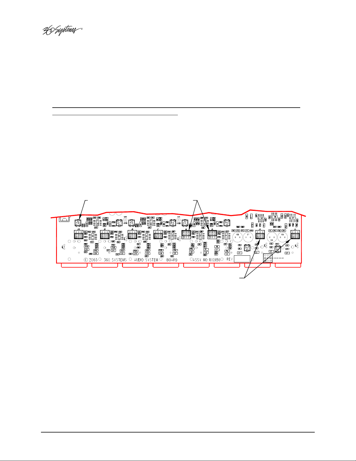
Analog/Digital Audio Selection on page 109.
There are four adhesive-backed rubber feet on the Image Server. These may need to be removed
when rack mounting the unit.
In North America, the Image Server will usually be mounted in a 19” rack enclosure having 10-24
or 10-32 tapped holes. In countries with metric standards, the user will need to supply appropriate
fasteners.
Cables attached to the rear of the Image Server should be supported by the rack mounting rails.
Do not support substantial cable weight from the Image Server.
Remove the front panel to expose the rack screw slots. Fasten the Image Server into the rack using
#10 flat-head Phillips screws (provided in North America). Replace the front panel. Tighten the
front panel access screws.
Important Installation Notes
System Cooling
When many pieces of equipment are mounted in an equipment rack, a considerable amount of
heat may be produced, which must be removed efficiently. Further, a lower operating temperature
will make equipment operate more reliably, and it will last longer. In the extreme case, excessive
temperatures cause rapid equipment failure, and damage which can be difficult to repair.
Heat in an equipment rack should be removed by forced air. This is often accomplished by
blowers installed in the top of the rack, venting into the room. An alternative is to draw hot air
from the top of the rack into an air-conditioning return duct, and not vent it into the equipment
room; cold air should be ducted into the bottom of the rack.
The optimum air temperature for cooling electronic equipment is 25° C (72° F). When many
pieces of equipment are contributing to the heat load, a substantial air-flow will be needed, and the
inlet temperature may need to be lower.
Check These Points
• Are all ventilation holes in the Image Server free of obstruction?
• Can blowers or HVAC system adequately remove heat from the equipment rack?
• Have you measured the actual temperature inside the rack? Do this near the top.
• Verify that the HVAC system is not on a timer that can shut off on weekends or holidays.
• What procedures are in place to protect the equipment when the HVAC system fails?
Page 18 MAXX Owner’s Manual
Page 19

Important Installation Notes
Power Conditioning
It is good practice to operate an on-air video server from an Uninterruptible Power Source, or UPS.
All utility power systems experience occasional transient events, including brownouts and
dropouts, which are capable of taking a server off the air. It is the station operator’s job to plan for
and overcome such contingencies.
UPS units suitable for smoothing short-term power line problems come in two varieties:
Change-over UPS Design
This design senses drop-outs and low-line voltage, and switches its output to an internal inverter
operating from a battery. This UPS is low in cost, and is most often used in non-critical
applications such as desk-top computers. A disadvantage is that it may create its own power
transients when switching between utility power and its inverter supply. . For this reason 360
Systems does not recommend this type for use with Image Server.
Continuous Conversion UPS Design
This improved design continuously converts utility power to DC, stores it in a battery, then
produces isolated AC power from an inverter. It never switches, and is immune to input transients,
brownouts, and blackouts. Models are available with batteries of almost any size, making the
continuous-conversion UPS suitable for transient suppression or long-term operating power in the
absence of utility power.
Recommended UPS Models
The following makes of continuous conversion UPS systems are suitable for use with 360 Systems’
Image Server products:
APC Smart-UPS 2200-XL
Eaton/Powerware Corporation, Model 9125, www.powerware.com
This unit is available in several different configurations to accommodate various current
load and power failure support times.
The minimum requirement for maximum current load for a single MAXX is 2 amps.
Operating Environment
A video server is the most critical element in a broadcast operation. Its installation should safeguard
it from every external event that can interfere with it doing the task expected of it. 360 Systems’
engineers have experience with thousands of installations, and have become aware of a number of
environmental factors that can adversely affect performance. Two of these have already been
discussed: power conditioning and inadequate cooling. Two others, less obvious, should also be
considered:
MAXX Owner’s Manual Page 19
Page 20

Important Installation Notes
RF Interference by Cell Phones
Many people are not aware that cell phones can attain a very substantial power output, even when
no conversation is taking place. You may have experienced the effect of a cell phone interfering
with a common desk phone placed nearby. Carrying a cell phone into a machine room where it is
in close proximity to broadcast equipment and its associated wiring is unwise. They are able to
interfere with serial control commands, video synchronization, and in some cases can crash the
CPU in equipment.
Some major broadcasters prohibit the carrying of cell phones into certain machine areas. 360
Systems believes that the risk of undesired equipment behavior from their RF fields is very real.
Static Discharge
Static electricity discharge is accepted by most people as an inevitable consequence of living in a
dry area. It is, rather, a result of floor coverings that may enhance appearances, but are
inappropriate for use around critical pieces of broadcast equipment. Static discharge can do two
adverse things:
• Discharge into a connector can—and will—destroy internal circuitry of equipment. The result
will always be difficult to diagnose and repair.
• Discharge to equipment frames or wiring can crash a CPU and take the station off the air. The
event may seem random or unrelated to static, but it is clearly a catastrophic event—and one
that can repeat indefinitely as humidity varies.
Several steps can be taken to protect equipment from static discharge:
• Do not install critical broadcast equipment (video servers) in a room with carpeting.
• Connect equipment racks directly to an earth ground with a heavy copper conductor.
• Do not operate equipment with a lifted safety ground (green frame ground).
• Install a humidifier to reduce the level of static discharge.
About Image Server Software
The Image Server is shipped with its application programs and operating system installed.
The first time that it is started, it must be connected to a keyboard, monitor and mouse. The Image
Server will ask you to accept the Software Licensing Agreement before it will operate. This screen
will only appear during the initial startup.
The CD-ROM drive is intended only for installing software. It may not be used to load video or
audio program content.
If for any reason it becomes necessary to reinstall any software, refer to the Maintenance chapter
for instructions.
Page 20 MAXX Owner’s Manual
Page 21
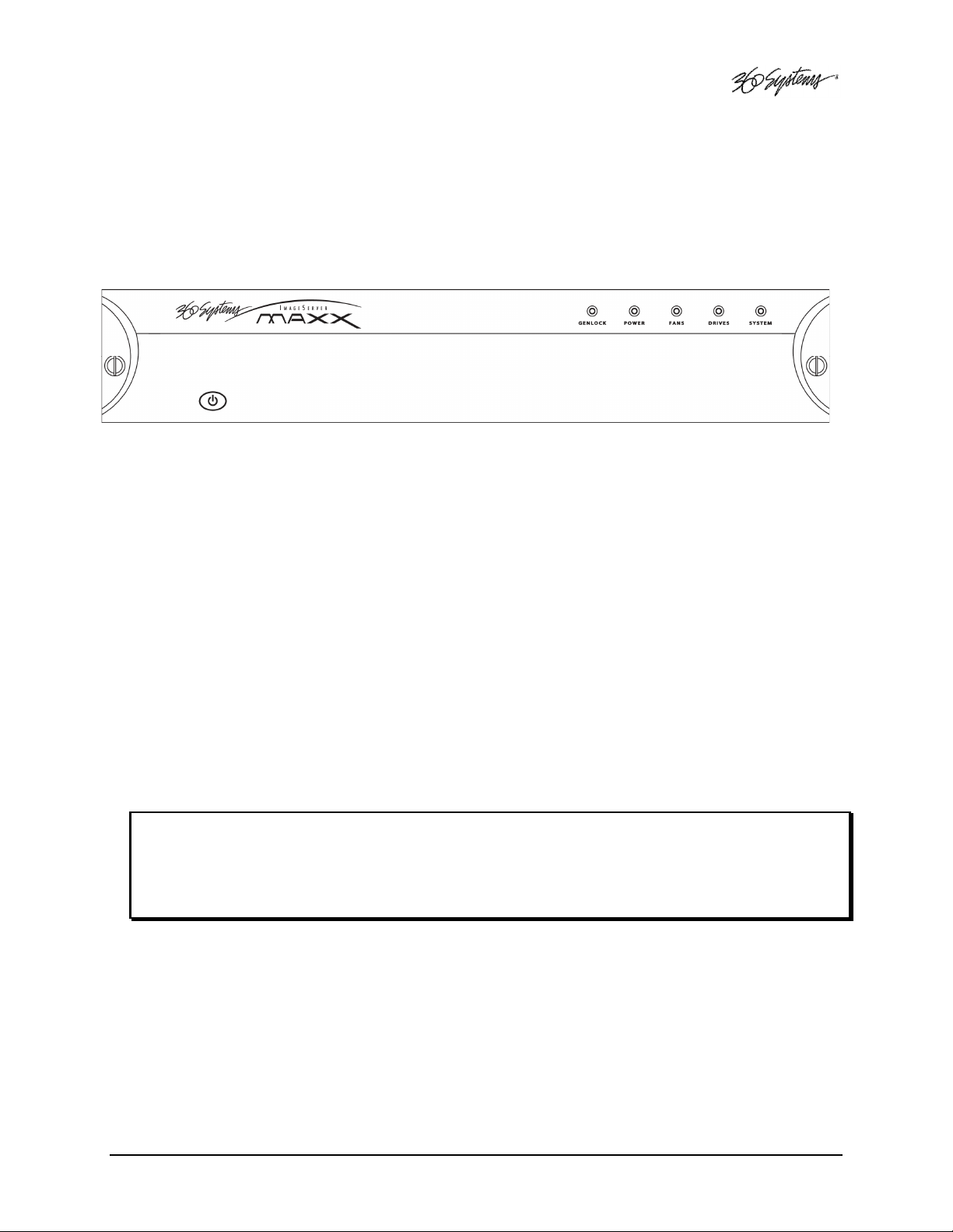
Image Server Hardware Interface
Front Panel Features
Power ON/OFF button
The blue front panel button initiates start-up and shut-down of the Image Server. Press it
momentarily to start the server. A sequence of start-up screens will appear, ending with the 3channel graphic user interface.
When the Image Server is running, pressing the blue button momentarily will cause the system
to begin an orderly shutdown. This can also be initiated from the GUI by selecting
START > SHUTDOWN > SHUTDOWN. In most cases the power will shut off automatically,
however if the front panel lights begin to blink the file system has been properly closed and it is
safe to force the power off by holding the front panel button in for 4 seconds.
In the event that the system has stopped responding to commands and will not shutdown, hold
the button in for 4 seconds to force a power down.
Do not use the rear panel switch on the power supply to shut down the Image Server. Abrupt
power loss can cause loss of information stored on the disk array. The rear panel power switch
can be used to prevent re-application of power during service procedures once the normal shut
down sequence is complete.
CAUTION:
LOSS OF DATA CAN OCCUR IF THE POWER IS TURNED OFF WITHOUT A SHUTDOWN.
USE THE FOUR SECOND SHUTDOWN ONLY IF THE SYSTEM IS NOT RESPONDING OR
THE SHUTDOWN PROCESS DOES NOT TURN THE POWER OFF AUTOMATICALLY.
Indicators
Five blue LED Status Indicators appear on the front panel. The POWER, FANS, DRIVES and
SYSTEM indicators are illuminated continuously when the system is functioning normally.
GENLOCK will be off when Internal Sync is selected, and illuminated when Genlock is
selected. See the table Front Panel Indicators on page 105 for diagnostic meanings.
MAXX Owner’s Manual Page 21
Page 22
CVBS
SDI
IN
IN
1
1
SDI
CVBS
OUT
OUT
1
1
MADE IN USA
SDI
CVBS
CVBS
OUT
OUT
2
2
WESTLAKE VILLAGE, CALIFORNIA, USA
OUT
SDI
OUT
3
3
41 2 3 5 6
CH 1-3
LTC IN
CH 1-3
LTC OUT
GENLOCK
INPUT
(6) opto-isolated inputs, (6) status outputs
ANALOG
DIGITAL
NET 2NET 1
MAIN IN R
AUX IN L/R
300
N
/
S
FROM
Rear Panel Drawing
INPUT
MAIN IN L
MAIN IN L/R
MAIN 1 R
AUX 1 L/R
MAIN 1 L
MAIN 1 L/R
MAIN 2 R
AUX 2 L/R
OUTPUT
GIGABIT LAN
GIGABIT LAN
MONITOR
GPI
11 12 13 14 15 16 17
Figure 1: Rear Panel Features
SERIAL
USB
11. GPI port, 25-pin female:
9. Mouse port
10. Keyboard port
14. Genlock Input
13. Gigabit Ethernet ports
12. SVGA monitor port
17. SDI video input
16. (3) SDI video outputs
15. LTC time code output
MAIN 2 L
MAIN 2 L/R
10
KEYBD
MAIN 3 R
AUX 3 L/R
MOUSE
MAIN 3 L
MAIN 3 L/R
CH 1 REC/PLAY
CH 2 PLAY
CH 3 PLAY
100 - 240 VOLTS, 50 - 60Hz, 2 AMPS MAX
7 8 9
or +4 balanced analog)
or +4 balanced analog)
1. (3) serial control ports (EIA-422)
2. (6) XLR-3 audio outputs (AES/EBU digital
3. (2) XLR-3 audio inputs (AES/EBU digital
4. LTC time code input
5. (3) Composite video outputs
6. Composite video input
7. AC Power connector
8. AC Power switch
Page 22 MAXX Owner’s Manual
Page 23

Rear Panel Features
Video Inputs
The Image Server records video on channel #1. It has separate BNC inputs for SDI (serial
digital per SMPTE 259M) and analog video (CVBS) signals. Both video inputs have a fixed 75ohm termination. The graphic user interface selects between the two. Encoding is performed
in MPEG-2 format within the server.
Video Outputs
Video outputs are provided in SDI and Composite (CVBS) formats simultaneously. Digital
video appears in SDI format at 270 Mb/s and conforms to SMPTE 259M. Analog video is
composite (CVBS).
Audio I/O
The Image Server provides audio inputs and outputs in three formats:
• Balanced analog audio at a reference level of +4 dbu.
• Digital audio in AES/EBU format per AES-3-2000.
• SDI embedded audio, 4-channels
These multiple standards facilitate the transition from an analog studio to digital production and
broadcasting, and ensure that the server can operate with most equipment. Note that both
analog and AES/EBU audio signals are not available at the same time on a given input or
output. Internal jumpers select between analog or digital; however, each pair of inputs and
outputs can be set up differently, if desired. A set of XLR-3 connectors allows high-quality
connections to be made in either format. Embedded audio appears in the SDI output stream at
all times.
Analog Audio Capability
When the analog audio input format is selected, each video channel has two audio channels,
recorded together as a stereo pair. Internal trimmers allow adjustment to unity gain.
Digital Audio Capability
When AES/EBU digital audio is selected, each video channel has four audio channels, which
are recorded as two stereo pairs. Because a single XLR connector carries a stereo pair in
AES/EBU format, and only one (monaural) channel in analog, the server provides an extra pair
of audio channels when used with AES/EBU audio signals.
Embedded Audio Capability
When SDI embedded audio is selected, four audio channels are available for recording.
Embedded audio is always inserted in the video outputs. Note that discrete audio (analog or
AES/EBU) is also available on XLR connectors, at the same time embedded audio appears in the
video stream. Embedded audio has a 20-bit resolution.
MAXX Owner’s Manual Page 23
Page 24
Audio Word Size and Sample Rate
The Image Server employs 24-bit audio A/D and D/A converters, and records audio into a 24bit frame, regardless of the word size received. The sample rate is fixed at 48K. When using
the AES/EBU digital input, the 48K sample rate of the incoming digital audio must be derived
from the video genlock reference. If it is not, or if a different sample rate is used, the Image
Server’s input sample rate converters must be selected.
Encoded audio streams such as Dolby E® must be referenced to the video genlock, and the
input sample rate converters must be disabled when recording such streams.
Analog/Digital Audio Selection
The following drawing illustrates jumper positions to select between analog or digital audio.
Note that each output may be individually selected. As described earlier, when analog audio is
selected, only two channels are available, while selection of AES/EBU digital audio provides
two stereo pairs, one on each XLR connector. Both jumpers for each channel (Left & Right, or
Main & Aux) must be set together, either analog or digital. The Image Server must be power
cycled for jumper changes to take effect. For more detail, see Analog/Digital Audio Selection
in the Maintenance chapter.
GAIN ADJUST
JUMPER BLOCK PAIR SHOWN
IN DIGITAL POSITION
JUMPER BLOCK PAIR SHOWN
IN ANALOG POSITION
DIGITAL
ANALOG
Figure 1: Jumper location on audio card for selection of analog or digital audio.
Serial Control Ports
Each of the Image Server’s three 9-pin “D” connectors permits independent control of any of
the three video channels. They can accept serial commands in VDCP, Sony BVW or Odetics
protocol. The multiple serial ports allow simultaneous connection of an automation controller
and a desktop controller. See the chapter on Automation Control for further details.
Most broadcast automation systems, and some remote control panels, employ the VDCP
protocol. A list of supported VDCP commands will be found in Appendix B.
Many controllers used for transport, instant replay, and edit control employ Sony BVW or
Odetics protocol.
Page 24 MAXX Owner’s Manual
Page 25

Gigabit Ethernet Port
Gigabit Ethernet ports are provided on the Image Server. The NET 1
external transfer of program content between video servers. The server supports MXF file
transfer (MPEG-2, Op 1a and 1b), which allows content interchange between products from
different manufacturers, as well as file import in various formats from desktop editors.
The NET 2
NET 2 port is reserved for future use and is not active. Use only the NET 1
NET 2NET 2
NET 1 port is intended for
NET 1NET 1
NET 1 port.
NET 1NET 1
GPI Control
The Image Server provides six GPI inputs for control of machine functions, which appear on
the 25-pin GPI
contacts or an open-collector transistor output. GPI inputs are programmable, and can provide
machine control such as PLAY, STOP, or RECORD through simple external switches.
The Image Server also provides six GPI status outputs which may be used to confirm that a
command has been received, or for other purposes. The functions of these open-collector
outputs are programmable, and may be used to operate an LED, or they can be connected to a
suitable logic input. The pin-out for the GPI connector will be found in Connector
Specifications.
GPI connector. This “General Purpose Interface” can be connected to switch
GPIGPI
Genlock Sync Reference
A BNC connector is provided on the rear panel to receive a genlock signal. During normal
operation, the Image Server should be referenced to an external genlock reference in the form
of CVBS black. As with all video systems, this server and equipment connected to it must be
referenced to a common genlock source. The GENLOCK
termination.
An internal crystal reference is also provided so that the server can be used as a stand-alone
player, and also for convenience in performing tests in the laboratory. Use particular care
when operating the server with an internal reference, as synchronization with other equipment
is not possible.
Genlock Signal Quality
A genlock signal connected to the Image Server must conform to the RS-170A standard. PLL
circuits used within the server remove residual jitter from the genlock signal. This may
preclude the use of low-cost VCRs as signal sources, as they may introduce time instability
(wow) into their output, making them inaccurate as a genlock source.
GENLOCK input provides a fixed 75-ohm
GENLOCKGENLOCK
LTC Time Code Input
A LTC time code input is provided on the LTC IN
by means of the On-Screen user interface and recorded as a time code reference. The LTC
input provides a >10k ohm termination.
LTC IN BNC connector. This input may be selected
LTC INLTC IN
MAXX Owner’s Manual Page 25
Page 26

LTC Time Code Output
An LTC time code output is provided on the LTC OUT
means of the On-Screen user interface to output time code from any of the three video
channels during playback. The LTC output has a source impedance of <5 ohms.
LTC OUT BNC connector. It may be selected by
LTC OUTLTC OUT
Keyboard
Attach the alphanumeric keyboard to the purple 5-pin KEYBD
and manage clips with the On-Screen graphic user interface. Note that the server will only
recognize the keyboard if it is attached before power up.
KEYBD connector to control the server
KEYBDKEYBD
Mouse
A two-button scroll mouse is provided with the Image Server. Plug the mouse into the green 5pin MOUSE
MOUSE port. Do not use the USB ports, even if the supplied mouse is USB capable. Note
MOUSEMOUSE
that the server will only recognize the mouse if it is attached before power up.
Monitor
A VESA-compliant computer monitor may be connected to the 15-pin VGA video port. The
Image Server resolution is fixed at 1024 x 768 pixels, with a refresh rate of 72 Hz. This is bestviewed on 17-inch or larger monitors. 360 Systems does not provide monitors for the server.
Note: Do not use older monitors that are not VESA compliant. The server may not start
properly if an unsuitable monitor is connected.
Serial Port
The system board serial port is not used. Make no connection.
USB Ports
The system board USB ports are not used. Make no connection.
Power
An IEC mains socket is provided on the rear panel for power input. The Image Server will
accept world-wide power sources in the range of 100-240 volts AC, 50-60 Hz. The server is
shipped with a power cord appropriate for the region in which it is sold. Replace the power
cord only with one of the same type and rating.
DO NOT use the power supply switch to shutdown the Image Server. (See the section
Shutting Down Image Server on the next page.) The rear panel power switch should only be
used if the Image Server fails to shutdown after holding the front panel power switch for 4
seconds, and the shutdown procedure from the GUI is not possible. The rear panel power
switch can be used to prevent the application of power during service procedures once the
normal shutdown sequence has completed.
Page 26 MAXX Owner’s Manual
Page 27

Basic Operations
This section introduces the Graphic User Interface (GUI), its menus and operating controls. If you
want to skip ahead to learn how to record a clip, go to page 35. Skip to page 41 to read about
playing a clip.
The graphic user interface is a convenient way to manage Image Server operations. With it, you can
control recording and playout, set up video and audio formats, map remote control ports to video
channels, perform editing and make playlists.
All GUI software is pre-installed on the Image Server. It is also contained on the Image Server
software CD-ROM. The GUI is operated with a keyboard, mouse, and monitor connected to the
Image Server rear panel. During the first power on the system must be connected to a keyboard,
monitor and mouse. The Image Server will ask you to accept the Software Licensing Agreement
before it will operate. This screen will only appear during the initial startup.
The Image Server Desktop
The Image Server desktop is similar to many computer graphic interfaces, and is always running. A
task bar and start menu appear at the bottom of the screen. Use the Start menu button to launch
applications, manage the system or to shut down the server.
Launching the Graphic User Interface
The GUI launches automatically during boot up. If it has been closed, click Start, then Image
Server GUI to re-launch it. The GUI window can be moved or minimized as desired.
Shutting Down Image Server
Click Start, then Shutdown, then select either Shutdown to begin an orderly shutdown, or Full
Restart to do an orderly shutdown and Restart (without a full power down).
Alternatively, momentarily pressing the front panel power button will cause the system to begin an
orderly shutdown. Image Server will acknowledge the button press with an audible beep and the
front panel lights will begin to flash together. Any operation in progress will be halted, and any
unsaved work will be lost.
In most cases the power will shut off automatically. However, if the front panel lights begin to blink
the file system has been properly closed and it is safe to force the power off by holding the front
panel button in for 4 seconds.
In the event that the system has stopped responding to commands and will not reset by pressing the
front panel button, press and hold the button for four seconds to force a power down. Wait 5
seconds, and then the system may be restarted with another press of this button.
DO NOT use the rear panel power supply switch to shutdown the Image Server. Doing so may
cause loss of unsaved data, and may require the RAID drive array to re-synchronize – a process that
could take several hours. Shutdown the system only by momentarily pressing the front panel power
button, or through the GUI.
The Quick Restart option in the Start>Shutdown menu allows the GUI and video playback
application to be restarted without restarting the entire operating system. The Restart FTP Only
option will restart the FTP service without affecting video operation.
MAXX Owner’s Manual Page 27
Page 28
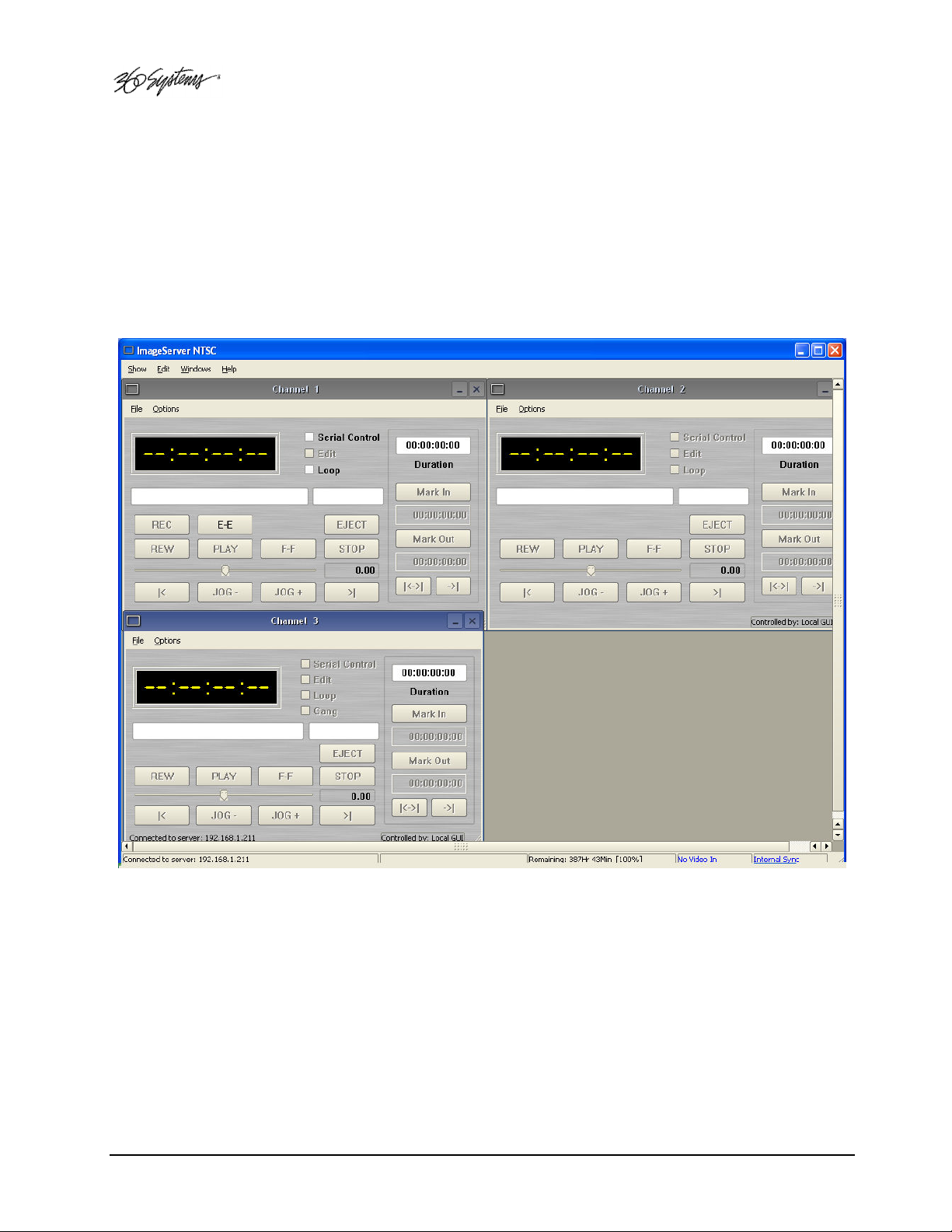
On-Screen Main Menu Bar
Once MAXX has successfully powered up, the VGA monitor will display the GUI of Figure 2. This
view provides
• A main System Menu bar for configuration operations
• A Status Bar that displays various system messages
• Three VTR-like transport controls, one for each of the three video channels.
Figure 2: Graphic User Interface with Clip Transport Windows
When using the mouse, all buttons of all channels will operate immediately, without first selecting a
window to activate it. (Channel 3 is active in the illustration above, indicated by its blue title bar.)
When using key commands, the active window is the only transport that will respond. Use the
CTRL+TAB key combination to change the active window in rotation, or use the mouse to activate
the desired window by clicking anywhere in it.
Windows can be moved, resized and overlapped by dragging the title bar, the edges or the resize tab
at the lower right corner of each window. The CTRL+TAB key combination will also bring the
activated window to the top, in front of all other windows.
Page 28 MAXX Owner’s Manual
Page 29

System Menu Bar
The System Menu bar contains four menus: Show, Edit, Windows and Help.
Show Menu
Contains selections for the three Channels and the clip management windows.
Channel 1
Channel 2
Channel 3
Opens the specified window if it is closed, brings it to the top and activates it.
Key Commands – F1, F2, F3
Clip List
Opens the Clip Navigator window if it is closed, brings it to the top and activates it. See page 52.
Key Command – Ctrl+L.
Find Clips
Opens the Clip Locator dialog. See page 53.
Key Command – Ctrl+F.
Edit Menu
Contains a single selection, Configuration. This opens the main System Configuration dialog. See
page 45.
Windows Menu
Choices in this menu change the way the windows are displayed. Use the CTRL+TAB key
combination to change the active window in rotation, or use the mouse to activate the desired
window.
Cascade
Arranges all open windows so that they are overlapping, but offset. It is useful as a starting
point to rearrange the windows. This choice is especially useful with small monitors.
Tile
Arranges all open windows so that each is fully visible at the same time. This choice is
especially useful with larger monitors. In case the Windows don’t tile as expected, select
Cascade to restore their original size and order, then select Tile.
In addition, there are selections for each open transport window. Selecting one of these brings that
transport to the top of the display and makes it the active window.
MAXX Owner’s Manual Page 29
Page 30

Help Menu
Contains a single item, About, which displays the Image Server software versions, serial number and
Unit ID.
The Status Bar
A status bar appears at the bottom of the window that provides system information to the user
including
CONNECTED TO HOST
status messages from the RAID system can also be displayed here.
Channel 1 is the only channel that can either Record or Play video content. Channels 2 and 3 can
play back content. All channels may be used at the same time.
Each channel can be controlled in two different views.
GENLOCK, INPUT VIDEO DETECTED
or
CONNECTION TO HOST REFUSED
1. The Transport View
2. The Playlist View
, and
TIME REMAINING—PERCENT FULL
are also displayed as diagnostics. Error and
. Messages such as
Page 30 MAXX Owner’s Manual
Page 31

The Transport Channel View
The Transport Channel View is shown in Figure 3. This is the default view of each channel. Basic
transport operations such as play, stop, record, and head/tail trimming appear in the Clip Transport
window for each channel. These operate in familiar VTR fashion.
Figure 3 - Transport Channel View
Transport Menu Bar
There are two menus, File and Options.
File Menu
Contains six selections in Channel 1, five in Channels 2 and 3.
New
Channel 1 only. Opens the Clip Navigator to allow naming of a new clip, then prepares the
channel for recording. See page 38.
Key Command – Ctrl+N.
Open
Opens the Clip Navigator to allow choosing a clip to load into the transport.
Key Command – Ctrl+D.
MAXX Owner’s Manual Page 31
Page 32

Save
Saves an edited clip using its existing file name.
Key Command – Ctrl+S.
Save As
Opens the Clip Navigator to allow saving an edited version of the clip with a new name. This
allows making alternate versions of a clip or making multiple segments of a master clip.
Key Command – Ctrl+A.
Playlist
Switches from Transport View to Playlist View.
Close
Closes the Transport window. This has the same effect as the Close box in the upper right
corner of the window. Note that this will not stop playback or eject a loaded clip.
Options Menu
This menu contains two selections.
Take Control
Takes control of the video channel from another user (the Serial Control, a Remote
Workstation, or if you are using a Remote Workstation possibly the local GUI.) This item is
grayed out when the window has control.
Key Command – Ctrl+T.
Configure
Opens the video channel’s Configuration dialog. See pages 35 and 51.
Key Command – Ctrl+C.
Page 32 MAXX Owner’s Manual
Page 33

The Playlist Channel View
The Playlist Channel View is shown in Figure 4. This view allows multiple clips to be loaded
in a “playlist” and played in sequence.
Figure 4 - Playlist Channel View
Playlist Menu Bar
There are two menus, File and Options.
File Menu
Open
Opens the Clip Navigator to allow choosing a clip to load into the transport.
Key Command – Ctrl+D.
Append
Opens the Playlist Selection dialog to allow choosing a Playlist to Append to the
currently loaded list. This can be done while playing to allow continuous playback
of new Playlists. See page 64.
Save
Saves an edited Playlist using its existing file name.
Key Command – Ctrl+S.
MAXX Owner’s Manual Page 33
Page 34

Save As
Opens the Clip Navigator to allow saving an edited version of the clip with a new name.
This allows making alternate versions of a clip or making multiple segments of a master clip.
Key Command – Ctrl+A.
Rename
Opens the Playlist Selection dialog to allow renaming the currently loaded Playlist.
Transport
Switches from Playlist View to Transport View.
Eject
Ejects the currently loaded Playlist in preparation for creating a new one. (It is not necessary
to Eject a list to load another saved list.)
Key Command – Ctrl+N.
Close
Closes the Playlist window. This has the same effect as the Close box in the upper right
corner of the window. Note that this will not stop playback or eject a loaded list.
Options Menu
This menu contains two selections:
Take Control
Takes control of the video channel from another user (the Serial Control, a Remote
Workstation, or if you are using a Remote Workstation possibly the local GUI.) This item is
grayed out when the window has control.
Key Command – Ctrl+T.
Configure
Opens the Playlist’s Configuration dialog. See page 63. Note that this is different than the
dialog for the video channel setup, which must be accessed from the Transport View
window.
Key Command – Ctrl+C.
Page 34 MAXX Owner’s Manual
Page 35

MAKING A RECORDING FROM THE GUI
Video recordings are made using the Transport View of Channel 1. Channel 1 can record or play
back clips but cannot do both at the same time. Channels 2 and 3 are playback only. Follow these
steps to record a clip on Image Server. Note that most of these configuration setting steps can be
skipped once an established workflow is in place.
Record Configuration Options
Set Channel 1 to the Transport View
If necessary, set channel 1 to the Transport View. Click FILE->TRANSPORT in the Channel 1
Playlist View to switch to the Transport View.
Setting the Sync Source
To use a genlocked source, select External Sync using the GUI as follows:
A. From the main menu bar select EDIT->CONFIGURE. The screen of Figure 6 appears.
Select the TIMING option.
B. Select EXTERNAL as the sync source.
C. Check that the front panel GENLOCK
GENLOCKED now appears in the bottom right of the main GUI window.
D. If necessary set the LINES and SUB-PELS settings. See System Timing on page 68.
About Genlock Signal Quality
A genlock signal connected to the Image Server must conform to the RS-170A standard. An
unstable genlock source may result in unwanted artifacts in the video output or recorded data.
To use a non-genlocked CVBS source, follow the instructions above but select either INTERNAL
or EXTERNAL Sync.
NOTE: The CVBS input of the MAXX is equipped with an Input Frame Buffer that allows recording
from non-genlocked sources. No configuration is required to use the frame buffer. Refer to Appendix
D for more information.
GENLOCK LED is now illuminated and the word
GENLOCKGENLOCK
MAXX Owner’s Manual Page 35
Page 36

Figure 5 - Timing Configuration Screen
Setting the Video Input Source
The MAXX can accept a video signal at either its composite video input (CVBS), or its serial digital
(SDI) input. Verify that the input to be used is currently active. For a discussion of the SDI –
Embedded Audio option, refer to Configuring Embedded Audio on Page 69.
Select OPTIONS->CONFIGURE from the Channel 1 Transport Window.
The Dialog of Figure 6 appears. Select the appropriate Video Input source by clicking the related
radio button in the Video Input Source section of the dialog. Click APPLY or OK.
Figure 6 - Channel Configure Dialog
Page 36 MAXX Owner’s Manual
Page 37

Arming the Audio tracks
The MAXX can record either two or four audio tracks according to a selection made in the Channel 1
Configuration window. When a selection is made it will be saved for future recordings.
Select OPTIONS->CONFIGURE from the Channel 1 Transport Window.
Refer again to Figure 5 - Timing Configuration Screen for a view of the Channel 1 Configuration
Dialog.
• Check Audio 1-2 if you wish to record on tracks 1 and 2 only
• Check Audio 3-4 if you wish to record on tracks 3 and 4 (only when using AES-EBU or SDI
Embedded audio input.)
• Check BOTH Audio 1-2 AND Audio 3-4 if you wish to record on tracks 1, 2, 3 and 4
• Uncheck all boxes if you don’t want to record audio.
• Check Closed Caption for all above cases if you want to record closed caption data into a
separate, dedicated track (See Setting the Recording Format below).
Bit-for-Bit® Recording & Playback
The recording, storage and playback of audio program material such as Dolby®-E, Dolby Digital
(AC-3) or DTS® requires that upon playout the data stream be identical to the original. Do not use
the audio sample rate converters when working with these encoded audio formats.
The Image Server and a Dolby® encoder must be supplied with the same genlock signal.
Audio Sync Reference
The audio sample rate is derived from the selected video sync reference. Audio is recorded at a
nominal 48K sample rate, so the 0.1% pull-down for 29.97 NTSC is taken into account when
generating the audio sample rate for color NTSC. There is no drop frame in PAL video.
Setting the Recording Format
Refer again to Figure 5 - Timing Configuration Screen.
Select either Main (Main Profile @ Main Level (4:2:0), or 4:2:2 (4:2:2 Profile@ Main Level) by
selecting the corresponding radio button. Refer to Appendix B for a discussion of Profiles.
Select either 1:I-Frame Only, 6:IBBPBB or 15:IBBPBB…
Refer to Appendix B for a discussion of the GOP structure.
Select the Bit Rate. The range is 4 – 50 Mb/s unless Main profile is selected. In Main profile, the
maximum rate is 15 Mb/s. Generally, very good quality video can be achieved at rates as low as
8 Mb/s with IBBPBB settings.
The Image Server always records Closed Caption data directly into the video. However, when using
bit rates below 10 Mb/s it is advisable to enable the dedicated Closed Caption track in the Arm
Tracks section described above. This will guarantee that the encoding process will not affect the
Closed Caption data.
MAXX Owner’s Manual Page 37
Page 38

Setting the Time Code Source
This function selects the time code source for newly recorded clips. A time code value is obtained
from the selected input source at the start of a new recording. Refer to Figure 6. Choose VITC, LTC
or Manual input source. For MANUAL, enter the desired time value for the first frame of the
recording in the Starting Time Code entry field.
Beginning Recording
When the steps outlined above in “Setting up for Recording” are done, you are ready to record.
Place Channel 1 in the Record Ready mode as follows.
A. From the Channel 1 Transport Window, Select FILE>NEW. The dialog of Figure 7 appears.
Figure 7 - Channel 1 Clip Navigator "New" mode
B. Note the Folder Structure in the FOLDERS window to the left. If you have not added any
folders (Refer to Creating Folders on Page 52) no folders will be shown. If you have already
created a folder structure you can select the destination folder for your clip at this time by
clicking on the folder you want it to be placed in. You can always move or copy it later as well.
Page 38 MAXX Owner’s Manual
Page 39

C. Enter a clip name using the keyboard. You may use up to 31 characters. Spaces may be
used; however, some characters other than upper or lower case letters and numbers may not
be used. These characters will not enter into the name field when typed. They include * ( ) +
= ; : ‘ “ < > , . / and ? A list of existing clips will appear in the large window, and can be
used as a name reference when creating new clip names.
Note: File naming is case sensitive. Upper case letters sort before lower case. The name FILE sorts
in the order shown, based on differing capitalization: FILE, File, fiLe, and file. When using the
Image Server with automation systems or other remote controls, it is not a good practice to
distinguish files only by differences in case.
D. The Channel 1 transport Window will display the words IDLE CUEING for two seconds or
less. When ready to record, the Channel 1 Transport Window will display IDLE READY.
Figure 8 - Channel 1 Ready to Record
E. You may now click the RECORD button at any time to begin recording. The yellow time
display counters will update the clip duration continually.
F. To stop recording, click STOP.
Note: An in-progress recording must be at least 10 seconds long before it will appear in the clip list.
Hitting the STOP button to end the recording after less than 10 seconds will also cause the clip to
appear in the clip list
MAXX Owner’s Manual Page 39
Page 40

USING E-E Mode to Monitor the Recording Source
The E-E button appears in the Channel 1 Record/Play window. It allows the input signal to be
monitored from the server output. E-E Mode toggles automatically as described below, but can also
be switched manually at any time.
When a new clip is created for recording, the input source is automatically switched ON to the
output—an E-E connection. When a clip is opened for play on Channel 1, E-E monitoring is switched
OFF.
When Channel 1 is switched to playlist mode, the E-E monitor is switched OFF. E-E mode cannot be
toggled while the channel is in playlist mode.
When E-E is ON, the input video signal is routed to the outputs. Manually toggle the E-E mode button
OFF to switch the output to the servers output, for conventional playback operation.
Under automation control, Auto E-E behavior is slightly different than under GUI control. The server
will remain in E-E ON mode until a transport control command (Play, Stop, Jog, etc) is received. After
receiving such a command, the server will remain in E-E OFF mode until record mode is entered. In
record mode, E-E mode is ON. As with GUI operation, automation controllers may send E-E ON and
E-E OFF commands to override the automatic operation.
Note that when in E-E mode the channel 1 video outputs are not timed to the genlock signal. This will
not be noticeable when connected directly to a monitor. However, there will be timing offsets when
feeding timed routers or switchers. The symptoms of this will vary depending on the particular
equipment, including horizontal picture shift or timing error indications. . If the input is not
synchronous with genlock, it may roll vertically. E-E mode is not intended to be used on-air, only as a
production tool.
Page 40 MAXX Owner’s Manual
Page 41

PLAYING A CLIP FROM THE GUI
Video Playback can be done on all three channels, individually or simultaneously. Channel 1
cannot Record and Playback at the same time. Follow these steps to play back a clip.
Beginning Playback
A. Select FILE>OPEN from the Transport Window of Channel 1, 2 or 3. The Clip Navigator will
appear per Figure 9.
B. Navigate the folder structure if necessary by clicking on the folders.
C. Select the clip you want to play by double-clicking on it.
D. When the Transport Window indicates Idle Ready, you can play the clip at any time by
clicking PLAY.
Figure 9 - Channel 1 Clip Navigator in “Open” Mode
Looping a Clip
Clicking on the LOOP checkbox in the Transport View will cause a clip to loop until LOOP is
unchecked or until you click STOP. LOOP may be checked or unchecked before or during
playback, but must be changed at least 2 seconds before the end of clip to take immediate effect.
MAXX Owner’s Manual Page 41
Page 42

Pausing a Clip
Click PAUSE at any time to pause a clip. Click again to resume. The PAUSE button is the
same key as the PLAY button.
Ejecting a Clip
Ejecting a clip effectively removes it from the transport. The channel will output Black. Press EJECT
to eject a clip.
Using Jog
The JOG + command will move to the next frame and go to Still. The JOG - command will move
to the previous frame and go to Still.
Using GO-TO
Click the arrows |< or >| to go to the next trim point (Mark In or Mark Out) in the selected direction.
When in Edit mode, an additional click in the selected direction will go to the actual beginning or end
of the entire clip.
Using Fast Forward / Rewind
F-F (Fast Forward) and REW (Rewind) buttons transport program material at high speed in the chosen
direction. Four speed choices are available in each direction. Click the button repeatedly for: 4x, 16x,
64x, and 128x. Audio does not play at these speeds.
Using Shuttle to Control Playback Speed
The Shuttle Control is a slider bar that controls playback speed. Playback speed control employs
varispeed algorithms that may skip frames. It is not a perfect fast motion mechanism.
The center position represents zero speed, or Still.
The right and left extents of the slider represent ±2x maximums.
The Shuttle control slider works in three basic ways: Snap-Back to still, Hold Speed, and Mouse
Wheel.
• In Snap-Back operation, click and drag the slide control to change speed. Releasing the slider bar
will let it snap back to zero speed, or still.
• For Hold Speed operation, position the cursor over the slider control scale (not the slider arrow)
and click the left mouse button to increment the speed control. The transport will run in the
selected direction at the selected speed without holding the mouse button down. The cursor
may now be moved over the Stop button to wait for the desired point.
• When using a scroll mouse, position the cursor over the slider scale and rotate the wheel to
increment speed. Rolling the wheel in opposite directions changes the direction the arrow slider
moves. To stop video, click the Stop button or the arrow slider.
Page 42 MAXX Owner’s Manual
Page 43

EDITING A CLIP
Edit controls are activated with the Edit check box. Several buttons are available to define the
beginning and end of a region within a clip; associated time code displays are also present.
These non-destructive Mark In and Mark Out trim points can be set to define a portion of a clip to
be played. These “edit pointers” do not create a new clip from the original material; they act like
virtual trims, and material outside of the trim points is excluded, but can be retrieved by resetting the
Mark pointers. After setting the Mark In and Mark Out points, clips will play between these points.
These edit values are saved with the clip.
Edits may be saved to the current clip by de-selecting the Edit check box, or choosing Save from
the clip window File menu. Save As works to save the edit points to a new clip name, even if the
edits have not been saved in the current clip. This is a great help while conducting an Edit-whileRecording.
Using Edit-while-Recording
Clips are most often edited after recording is complete, but it is sometimes desirable to create subclips while the recording is still in progress. This is the preferred way to extract sports highlights, for
example.
First, wait at least ten seconds after the recording begins. Open the recording on either Channel 2 or
3 by selecting the clip name from the
before it will appear in the clip list.)
Use the transport controls to select and mark the In- and Out-Points, as desired.
Without un-checking Edit, select
clip is created that will play only between the In-Point and Out-Point. This clip can now be played
on the third channel, or assembled into a playlist.
Next, use the transport controls to locate another set of In- and Out-Points for a second segment, and
repeat the Save As command.
As noted above, it is usually easier to leave the edit channel in Edit mode when you plan to make
multiple “Saved As” clips. If you de-select Edit with unsaved changes, you will be given a choice to
save or discard the edit points. Remember that you will be saving the edits to the file that is
currently being recorded. Re-editing is required to see parts of it outside the region defined by
Mark In and Mark Out, even if the recording continues after the editing session.
Marking the IN point
Sets the current time code value into the Mark In point time display. The Mark In button can capture
a time code value from the clip when it is still, or on-the-fly.
Mark In Display
Displays the time code of the Mark In point. When no Mark In point has been set manually, this
displays the Start of Message (SOM) time code (usually 00:00:00:00). Trim points will be
automatically rounded down to the nearest GOP boundary when edits are saved.
FILE>OPEN
FILE>SAVE AS
menu. (A recording must be 10 seconds long
, enter a new clip name, and click Enter. A new
MAXX Owner’s Manual Page 43
Page 44

The values in this display window may be set by two methods:
• Enter Mark In point from the keyboard: Use the mouse or Tab key to move between In
and Out fields. When a field is highlighted, enter a numeric value from the keyboard.
• Whether a clip is still or playing, press Mark In to capture a time code value from the clip’s
current position.
Marking the Out Point
Sets the current time code value into the Mark Out point time display. The Mark Out button can
capture a time code value from the clip when it is still, or on-the-fly.
Mark Out Display
Displays the Mark Out point time code. When no Mark Out point has been set manually, this
displays the EOM time code (originally the end time of the recording).
The values in this display window may be set by two methods:
• Enter Mark Out point from the keyboard: Use the mouse or Tab key to move between In
and Out fields. When a field is highlighted, enter a numeric value from the keyboard.
• Whether a clip is still or playing, press Mark Out to capture a time code value from the
clip’s current position.
Duration Display
Displays the total running time (TRT) of the current clip. TRT is defined as the difference in the time
codes between the first and last frames, plus one. For example, if the first frame of the clip is
00:00:00:00 and last frame displayed at the end is 00:00:01:15, the reported duration will be
00:00:01:16.
With NTSC drop-frame time code, the true play duration may not be the exact numerical value of
((Mark Out – Mark In) + 1) due to the discontinuities in the drop-frame time line. The true run time is
shown in the Clip Navigator.
Auditioning the Mark In Point (Review Clip Button)
The Review Clip button
|
<–>
|
cues the clip to the Mark In point (or SOM, if no Mark In point
exists) and begins playback. Review Clip will stop at the Mark Out point. The Mark Out point will be
displayed in Still mode.
The Review Clip button may be used to check the Mark In point without playing all the way through
the clip. After Review Clip is pressed and play begins, all of the standard transport buttons are
available for use.
Auditioning the Mark Out Point (Review Out Button)
|
The Review Out button
–>
may be used to audition the Mark Out point without playing all
the way through the clip. It will cue the clip to three seconds before the Mark Out point (or EOM, if
no Mark Out Point exists) and then begin playback. Review Out will stop at the Mark Out Point.
Page 44 MAXX Owner’s Manual
Page 45

SYSTEM CONFIGURATION
The following configuration options apply to the System as a whole and not to individual channel
transports.
Assigning Names to the Server and Transport Channels
The Image Server can be assigned a name that will be displayed along the top of the Main
GUI Window. Each individual channel transport can also be given a name.
To assign a name to the server or transport channels, click EDIT>CONFIGURE>NAMES
from the main menu pulldown.
The screen of Figure 10 is displayed. Use the keyboard to type in a name for any of the
selections. Names can be up to 31 characters in length. Spaces, digits and other nonalphanumeric characters may be used. Click APPLY to accept the name. The names will
appear in their appropriate windows immediately.
Figure 10 - Configure Names Screen
MAXX Owner’s Manual Page 45
Page 46

Programming GPIO Outputs
The MAXX has six General Purpose Outputs, referred to as GPO 1 through GPO 6. Each GPO can
be programmed to go active on the selected channel when one of the following events occurs.
IDLE - Activate when the transport returns to idle
PAUSED - Activate when the transport is paused
STOPPED - Activate when the transport is stopped
PLAYING - Activate when the transport is playing
RECORDING - Activate when the transport is recording
RAID System Fault - Activate when a RAID or System Fault occurs
NO GENLOCK - Activate when there is no genlock
NO VIDEO INPUT - Activate when there is no video at the selected input
PLAYLIST - Control GPO via playlist. (Refer to page 66.)
To program a GPIO output, select EDIT->CONFIGURE->GPO. The screen of Figure 11 is
displayed. GPO 1 through 6 are the 6 triggerable outputs. The checkboxes to the right of each
selection represent channel 1, 2 and 3. GPO 5 is shown with the trigger option pulldown expanded.
To activate one of the GPO, pulldown the event menu and select which event will activate the GPO.
Select an associated channel where applicable by checking the channel checkbox. Click APPLY to
activate.
Figure 11 - GPO Configuration Screen
Page 46 MAXX Owner’s Manual
Page 47

Programming GPIO Inputs
The MAXX has six General Purpose Inputs, referred to as GPI 1 through GPI 6. Each GPI can be
programmed to trigger one of the following events on a channel.
CUE Cue a clip
JUMP Cue selected clip for immediate playback (Playlist Mode only)
NEXT Prepare next clip in a playlist for playback (Playlist Mode only)
PAUSE Pause a clip
PLAY Play a clip
RECORD Start a recording
SELPREV In Playlist Mode – Navigate to clip above currently selected clip
SELNEXT In Playlist Mode – Navigate to clip below currently selected clip
STOP Stop a clip
To program a GPIO Input, select EDIT->CONFIGURE->GPI. The screen of Figure 12 is displayed.
GPI 1 through 6 are the 6 programmable inputs. The checkboxes to the right of each selection
represent channel 1, 2 and 3. GPI 5 is shown with the trigger option pulldown expanded.
To activate one of the GPI, check the checkbox for the channels of interest, then pulldown the event
menu and select which event will be triggered when the GPI goes active. Click APPLY to activate.
Figure 12 - GPI Configuration Screen
MAXX Owner’s Manual Page 47
Page 48

Configuring Linear Time Code (LTC)
The Image Server supports only drop-frame time code for NTSC operations. It may not be used with
non-drop-frame time code. LTC Out Source chooses which channel will control the LTC Timecode
output.
Configuring the Network
The Image Server provides a number of user settings that configure it for use as a practical network.
These will be found on the Configure Network tab shown below.
The NET
NET----1111 Ethernet port on the Image Server has a unique IP Address. In this way, each Image
NETNET
Server can be identified on the network.
Network Settings Tab
Use the Image Server graphic user interface to configure network communication settings. From
the Main Menu selection bar at the top of the screen.
Click EDIT>CONFIGURE->NETWORK
The screen of Figure 13 is displayed.
Figure 13 - Network Configuration Screen
Page 48 MAXX Owner’s Manual
Page 49

Each Image Server is shipped with a default network Host Name and IP Address. Qualified
network engineers may change these configurations to suit your specific network environment.
Factory defaults for networking are:
• Network Disabled
• Use DHCP
Disabling the Network [X]
This selection turns the network OFF or ON. The default is ON, but can be turned off to deny
access to/from the network for security purposes.
Enabling/Disabling DHCP [X]
Enabling DHCP will configure the network interface automatically.
If the DHCP box is not selected, the user may then manually enter assignments in the
following windows:
• IP Address ( Example: 192.168.1.20 )
• Net Mask ( Example: 255.255.255.0 )
• Default Router ( Example: 192.168.1.1 )
The Host Name and NTP domain name may be a fully qualified domain name, such as
edit1.mydomain.com. All other manually configured addresses must be properly formatted IP
addresses.
Saving Network Configuration
Click on OK, APPLY, or CANCEL to accept or abandon new entries.
MAXX Owner’s Manual Page 49
Page 50

Setting the Date and Time
Click EDIT->CONFIGURE->DATE/TIME. The dialog below appears.
Figure 14 - Time/Date Configuration Screen
Select the REGION and ZONE according to your geographical location and time zone by
scrolling with the scroll-bar as necessary and then clicking on the selected value.
Set the TIME and DATE by clicking on the Time/Date field and navigating the clock and
calendar.
Check Automatic Updates to enable automatic updates using the Network Time Protocol
(NTP). Refer to Network Time Protocol on page 78.
Note: A System Restart is required for a Time Zone change to take effect
Page 50 MAXX Owner’s Manual
Page 51

Calibrating Channels
Setting the SC/H Phase
Refer to Figure 15. This parameter adjusts the Sub-Carrier/Horizontal phase relationship. Use a vector
scope to view the phase relationship and adjust the setting. Changes to the setting are effective
immediately without clicking Apply or OK. The adjustment range is ±90°.
Setting the Audio Delay
Refer to Figure 15. Audio timing relative to picture output can be configured for audio channels 1-2
and 3-4. The value is set in millisecond increments, plus-or-minus 1,000ms (up to 1 second). The
setting is applied to a clip when it is loaded for playback. This can compensate for systems issues
downstream from the server that result in leading or lagging audio.
Figure 15 - Playback Channel Configuration
MAXX Owner’s Manual Page 51
Page 52

CLIP NAVIGATOR
MAXX provides a powerful Clip Navigator for finding and selecting clips. Clip Navigator allows the
user to delete, name and rename clips.
• Rename and Delete Clips
• Create, name and rename “folders”.
• “Nest” folders within other folders.
• Freely Move, Copy and Rename clips within the folder structure.
• Find Clips within the folder structure.
• Clips can be dragged and dropped anywhere on a Transport for immediate playback.
• Selected single or multiple clips can be dragged into a Playlist. See page 59.
Creating Folders
To create a folder:
A. Click SHOW->CLIPLIST from the main pulldown menu.
B. The Clip Navigator of Error! Reference source not found. is displayed. Right-Click
on the folder icon displayed under the FOLDERS window.
C. Select NEW FOLDER from the pulldown. Enter the folder name in folder name dialog
D. Click OK.
E. A “nested” structure can be created by repeating the procedure with an existing
folder selected. The new folder will be created “under” the selected folder.
Figure 16 – Clip Navigator
Page 52 MAXX Owner’s Manual
Page 53

Renaming and Deleting Folders
To Rename a folder, right click on the folder and select Rename Folder from the popup menu.
Note that renaming a folder should be avoided when it contains clips included in playlists. The path
names in the playlist will not be updated and the clips in the renamed folder will be listed as
“MISSING” when the playlist is loaded.
To Delete a folder, first delete or move all of the clips and subfolders it contains. Then, right click on
the folder and select Delete Folder from the popup menu.
Navigating Folders
Once a folder structure is created, it can be easily navigated with the Clip Navigator. Move from
folder to folder simply by clicking on the folders in the FOLDER window. The view will
automatically expand if folders are “nested” within folders. Figure 17 shows a 3 level nested folder
structure.
Figure 17 - Clip Navigator with folders
Moving and Copying Clips
Clips can be moved and copied from any folder to any other folder. Note that moving a clip that is
included in a playlist will make it unavailable in that playlist. Also, if an automation system is in use,
moving a clip out of the folder assigned to the serial port will make it unavailable to the automation
system.
MAXX Owner’s Manual Page 53
Page 54

To move a clip to another folder:
A. Expand the folders in the FOLDER window so that the destination folder is visible.
B. If necessary, you can limit the number of clips displayed by typing a string in the
FILTER window. For example, typing “AT” in the filter window would limit the
display to all clips that contain “AT” somewhere in the clip name. Pressing the
Clear button restores the complete display.
C. Navigate to the clip location.
D. Drag the clip to the destination folder by placing the cursor over the clip, holding
down the left mouse button and “dragging” it to the destination folder. Release
the left mouse button to “drop” the clip into the destination folder.
E. MAXX 6T will list two options. MOVE HERE or COPY HERE. Select MOVE HERE
to delete the clip from the original directory. Select COPY HERE to leave the
original copy intact. . Note that this is a “virtual” copy, both clip names refer to
the same data on the disk.
Renaming and Deleting Clips
Clips can be renamed by right clicking on them with the mouse, then selecting Rename from the
pop-up menu.
Clips can be deleted by right clicking on them with the mouse, then selecting Delete from the popup menu.
Sorting Clips
Clips can be sorted in forward or reverse order by any of the columns by clicking once or twice on
the column heading. The previous sort is maintained so for instance if you sort by Name then by
Profile, the clips of each Profile will be sorted by Name.
Filtering the Clip Display
You can limit the number of clips displayed by typing a string in the FILTER field. For example,
typing “AT” in the filter field would limit the display to all clips that contain “AT” somewhere in the
clip name. Pressing the Clear button restores the complete display.
Finding Clips
Clips can be easily found using the Clip Locator. To locate a clip:
A. Click SHOW>FIND CLIPS. The Clip Locator screen of Figure 18 appears.
B. Select a “root” folder to begin a search by selecting the folder from LOOK IN.
C. Check Search Subfolders to search in folders “under” the selected folder.
D. Check Case Sensitive to make the search case-sensitive.
E. Check Stop After First Match to find only the first match.
F. Check Use Regular Expressions to search for the string of interest ANYWHERE in the clip
name. With Regular Expressions unchecked, the search will match only clips that BEGIN
with the string entered at FIND.
Page 54 MAXX Owner’s Manual
Page 55

G. Optionally, Enter a string in the FILTER field to limit the number of clip displayed. For
example, entering “AT” in the FILTER field will limit the display to only clips containing “AT”
in their clip name. Pressing the Clear button restores the complete display.
H. Enter a name or part of a name in the FIND field. Press ENTER to initiate the search. The
clip(s) will be displayed according to the rules set by the checkbox settings.
Figure 18 - Clip Locator
Finding Clips Using Wildcards
The following wildcard conventions may be used in a search.
*
? Match any single character.
Match anything. For example, to find all clips starting with “xyz”, use the pattern “
find all clips containing “2008” use “
*2008*
”.
xyz*
”. To
MAXX Owner’s Manual Page 55
Page 56

Finding Clips Using Regular Expressions
A regular expression (or RE) specifies a pattern to be matched in a clip name.
Regular expressions can contain both special and ordinary characters. Ordinary characters just
match themselves. Thus, the RE “
so this and any other clip name with “night” in it would be placed in the list of found clips.
The following special characters are supported:
.
(dot) This matches any single character. “a.c” matches “abc”, “aac”, “a2c” and “a c” but
not “acd”.
^ (caret) This matches the start of a clip name. To find all clips starting with “xyz”, for
example, use the Regular Expression “^xyz”.
$ Match the end of the clip name. To find all clips ending in “xyz” use the RE “xyz$”.
< Match the beginning of a word. For example “<Show” will match all clip names
containing a word that starts with “Show”, such as “Now Showing”, but not “LateShow”.
> Match the end of a word.
* Match zero or more repetitions of the preceding character. G*N “.*” will match anything –
“G.*N.*” will match “Georgia Evening News” or “Good Night”
night
” would match the “night” in the clip name “Tonight Show”,
+ Match 1 or more repetitions of the preceding RE.
? The preceding Regular Expression term is optional. “ab?c” will match “ac” or “abc” but not
“adc”.
[ ] Used to indicate a set of characters. Characters can be listed individually, or a range of
characters can be indicated by giving two characters and separating them by a "-". Special
characters are not active inside sets. For example, [a+$] will match any of the characters
"a", "+", or "$"; [a-z] will match any lowercase letter, and [a-zA-Z0-9] matches any letter or
digit. If you want to include a "-" inside a set, precede it with a backslash, or place it as the
first character. You can match all characters that are not within the set by making "^" as the
first character of the set; "^" elsewhere will simply match the "^" character. For example,
[^7] will match any character except "7".
SPACE A space is treated as an ordinary character. “ Show “ (<space>Show) will match “Tonight
Show” but not “Now Showing” or "NewShow”. “ “ will match any clip with a space in the
name.
The subject of Regular Expressions is much larger than can be completely covered here. They are
used in several different operating systems and programming languages. Further information can be
found on the internet and in books on Regular Expressions and Linux.
Page 56 MAXX Owner’s Manual
Page 57

USING PLAYLISTS
MAXX’s Playlisting software provides an extensive set of capabilities for building, editing and playing
complex sequences of program content. Advanced Playlisting appears as on-screen windows, with a
clean Graphic User Interface that makes it easy to run with no extra equipment. It’s invaluable for
building commercial breaks, news rundowns, still-store and clip lists. You can create and store as
many playlists as needed, each with its own unique name. For many users, Advanced Playlisting
may be all that’s needed to go to air. The Playlisting software has the following features and benefits.
• Drag-and-drop playlist building and editing on a graphic interface
• Edit lists while they’re running
• Start at any point in a list
• Displays run time for clips, plus segment length and total remaining time
• On-the-Fly commands for Pause, Skip, Hold, Next and Jump functions
• Append a playing list with a saved playlist
• Six programmable GPI Output events embedded in playlist clips
• Programmable time-of-day start for a playlist
• Generates an As-Run Log
• Set rules for deleting unneeded material on the playlist
• Simple text format allows playlists to be created, viewed and edited offline
• FTP access allows playlists to be transferred between Image Servers or to/from a PC
MAXX Owner’s Manual Page 57
Page 58

The Playlist view
The Playlist View for channel 1 is shown in Figure 19. Its functions are briefly described
here. Table 1 provides an overview of Playlist control functions and their associated hotkeys.
Figure 19 - Channel 1 Playlist View
FUNCTION DESCRIPTION / REFERENCE INVOKE HOT-KEY
PLAY/ PAUSE
STOP/ SHOW
CUE
NEXT
JUMP
LOOP
EDIT
ARM START TIME
HOME
Play / Pause a clip ( Page 41, 61 ) PLAY Button P or SPACE
Stop / Show First Frame ( Page 61 ) STOP Button S
Cue a clip ( Page 61 ) CUE Button C
Prepare next clip for playback ( Page 62 ) NEXT Button N
Jump to the selected clip ( Page 62 ) JUMP Button J
Check to loop a Playlist ( Page 61 ) LOOP
Checkbox
Check to enable editing ( Page 64 ) EDIT
Checkbox
Enable Scheduled Start Time ( Page 61 ) ARM START
TIME
Checkbox
Scroll to currently playing Clip ( Page 62 )
Table 1 - Playlist Control Functions
HOME
Button
L
E
T
H
Page 58 MAXX Owner’s Manual
Page 59

Creating and Running a Playlist
To Create a Playlist (Using channel 1 in the example):
A. Change the transport for Channel 1 to the Playlist View. Click FILE->PLAYLIST in
the Channel 1 transport pulldown menu. The window of Figure 20 appears.
B. Click the EDIT check box to put the channel into edit mode.
C. Click SHOW->CLIP LIST from the main menu to open the Clip Navigator. Both
windows are now visible.
D. Double click on a clip in the Clip Navigator to add it to the Playlist. The clip will appear
in the playlist. The first clip will indicate a status of CUED. Alternately, click on any clip
and hold the mouse button as you move the cursor to the playlist. Let go of the button
when the cursor is over the position that you want the clip to appear in the playlist (drag
and drop).
E. Repeat the procedure to add more clips.
Figure 20 - Channel 1 playlist with Clip Navigator
MAXX Owner’s Manual Page 59
Page 60

F. Click PLAY to run the playlist. The clips will be played in the order they were entered in
the playlist. The currently playing clip will indicate a status of PLAYING. The next clip on
the list will indicate a status of CUED
Figure 21 – Active Playlist
G. To SAVE the Playlist select FILE->SAVE-AS. Enter a file name. Click SAVE.
H. To SAVE an existing playlist without changing the name, use FILE->SAVE.
Status Indications
Status refers to what has taken place, is now taking place, or will take place with regard to each clip.
BLANK W
CUEING P
CUED Y
PLAYING G
DONE G
MISSING RED C
CLIPPED G
PAUSED G
SKIPPED G
HITE
URPLE
ELLOW
REEN
RAY
RAY
REEN
RAY
C
LIP IS AVAILABLE TO PLAY
C
LIP IS TRANSITIONING TO A CUED STATUS. MAX TRANSITION TIME IS 4 SEC
C
LIP IS READY TO PLAY ON COMPLETION OF THE PRECEDING CLIP, OR WHEN THE
PLAYLIST STARTS, IF NOT PRESENTLY RUNNING
C
LIP IS ACTUALLY PLAYING
C
LIP HAS PLAYED COMPLETELY, FROM FIRST FRAME TO LAST FRAME
LIP WAS NOT FOUND
C
LIP BEGAN PLAYING, BUT DID NOT COMPLETE
C
LIP HAS BEEN PAUSED. FURTHER, WHEN
NOT ADVANCING
C
LIP WAS SKIPPED, EITHER BY A
SKIP
CHECKBOX WAS SELECTED
.
.
.
NEXT
PAUSE
OR
IS ASSERTED THE PLAYLIST IS
CUE
OPERATION, OR BECAUSE THE
.
.
.
Page 60 MAXX Owner’s Manual
Page 61

Loading a Playlist (FILE>LOAD)
Click FILE->LOAD from the Playlist View to bring up the list of available PlayLists. Double-click on
a playlist to load it.
Saving a new Playlist (FILE>SAVE AS)
Once a Playlist has been created, it can be saved by selecting FILE->SAVE AS from the Playlist View
pulldown menu. Type in an appropriate name and click SAVE.
Saving an existing Playlist (FILE>SAVE)
An existing Playlist can be saved by selecting FILE->SAVE from the Playlist View pulldown menu.
Type in an appropriate name and click SAVE.
Setting a Start Time for a Playlist)
Set a start time for a Playlist by entering a twenty four hour time of day in Hours, Minutes and
Seconds in the START TIME field (see Figure 19 ). Click on any field to edit the field. Check the ARM
START TIME checkbox to arm the start time. The ARM START TIME checkbox will automatically
uncheck itself once the playlist has started
Stopping a Playlist (STOP)
Click STOP to halt a Playlist.
Pausing a Playlist (PLAY/PAUSE)
When a Playlist is running, the PLAY key will change to indicate PAUSE. Pressing PAUSE stops the
Playlist immediately, on the current frame of a clip. Pressing it again will resume playback.
Cueing a Clip (CUE)
When the Playlist is running, click CUE to immediately prepare a selected clip for playback.
When the current clip is finished playing, the Playlist will play the Cued clip, followed by all
subsequent clips. This allows the user to skip over clips that appear in the list between the currently
playing clip and the selected clip.
The user may also re-cue a clip that has already been played. In this case, the Playlist will restart
from the selected clip, and all subsequent events will be played (or re-played) in sequence. When
the Playlist is stopped, CUE will prepare the selected clip to play when Play is pressed, or the list is
started automatically by Arm Start Time.
Looping a Playlist (LOOP [X] )
To loop the entire playlist after the last clip completes, check the LOOP checkbox at any time. Upon
un-checking, the list will play to completion and then stop.
Showing the First Frame of a CUED clip (SHOW)
When a clip is cued, the STOP button legend changes to SHOW. Pressing it will display the first
frame of the cued clip.
MAXX Owner’s Manual Page 61
Page 62

Preparing the Next Clip for Playback (NEXT)
When a Playlist is stopped, click NEXT to prepare the next clip in the Playlist for playback. While
the Playlist is running, NEXT will immediately begin playing the next clip in the Playlist. (The next
clip may require several seconds to load and cue for a seamless transition.) If the next event in the
Playlist is a HOLD, the NEXT command will move to the Hold event, and video will display black.
Jumping to a selected Clip (JUMP)
Click JUMP to cue any selected clip for immediate playback; this permits jumping over intervening
clips. JUMP also allows clips that have already been played to be immediately re-cued and played.
In this case, the Playlist will restart from the selected clip, and subsequent events will be re-played in
sequence.
Automatically scrolling to the currently playing Clip (HOME)
Click HOME to make the currently playing clip visible in the List View window. . If no clip is
playing, then the currently-cued clip is displayed. This is helpful if you have manually scrolled
elsewhere in large Playlist. Once this is done, the display will also maintain the currently-playing clip
within the window, if EDIT is off
Page 62 MAXX Owner’s Manual
Page 63

Setting the Maximum Number of Played Items to Keep
To set the number of played items to be retained in a playlist:
Click OPTIONS>CONFIGURE from the Playlist View of the channel pulldown. Use the
thumbwheel UP and DOWN scroll button to increase or decrease the number of clips to
retain. The default value of zero will retain ALL Clips.
Figure 22 - Channel Playlist Configure Screen
Enabling As-Run Logging
To enable As-Run logs, Click OPTIONS>CONFIGURE from the Playlist View of the Channel
Transport. Check the Enable As-Run logging to enable As-Run logging. Uncheck the box to
disable As-Run logging. When enabled, a check mark will appear next to the As-Run log label,
and files played by a playlist will be written to an As-Run log. As-Run logs are available only
through FTP downloads; they cannot be viewed or printed from the Image Server. After logging
into an Image Server, select the ASRUN folder. All logs are stored in this location, and have the
extension “.arl”. Refer to APPENDIX E – AS-RUN LOGGING for more details about As-Run
logging functionality.
Viewing, Editing and Archiving Playlists
Playlists can be accessed via the MAXX’s FTP feature, allowing several capabilities:
• Lists can be backed up on a PC, and sent to another Image Server.
• Lists can be viewed and printed from the PC
• Lists can be edited or created on the PC and uploaded to the Image Server.
Playlists are found on the MAXX FTP directory in the lists folder. They are simple text files with
the extension .lst. Refer to APPENDIX D – PLAYLIST MANAGEMENT DETAIL for more
information.
MAXX Owner’s Manual Page 63
Page 64

EDITING PLAYLISTS
Removing a Clip from a Playlist
To remove a Clip from a Playlist:
A. Make sure the clip to be removed is not PLAYING or CUED
B. Position the cursor over the Clip and right-click. Select REMOVE from the pulldown menu.
Removing All Clips Above or Below the Selected Clip
All clips above or below the selected clip can be removed unless a CUED or PLAYING clip is
affected. These options will “grey out” if removal is not allowed for this reason.
To Remove All clips above a selected clip:
A. Move the cursor over the clip to select it
B. Right click the mouse and select Remove All Above from the pulldown menu.
To Remove All clips below a selected clip:
A. Move the cursor over the clip to select it
B. Right click the mouse and select Remove All Below from the pulldown menu.
Inserting a HOLD into a Playlist
The HOLD command inserts a hold (wait) event in a Playlist immediately before the selected clip.
The PLAY or JUMP command will restart a Playlist after it has stopped on a HOLD line. The HOLD
command is also available in the Playlist Item Context Menu, accessed by right-clicking in the
Playlist item window. If a Programmed Start Time has been set and is armed, the Playlist will resume
when the Programmed Start Time occurs. See Page 61 for instructions on setting a programmed start
time.
Appending a Playlist (FILE->APPEND)
Make sure the EDIT checkbox is checked in the Playlist View window.
Click FILE->APPEND from the Playlist View to bring up the list of available PlayLists. Double-click
on a playlist to load it. It will appear at the end of the list after a label event that shows the name of
the appended list. This operation can be performed during playback, allowing a new playlist to be
loaded without interruption of programming.
Page 64 MAXX Owner’s Manual
Page 65

Changing the duration of Clips in a Playlist
Make sure the EDIT checkbox is checked in the Playlist View window. Position the cursor over a clip
and right-click. Select EDIT DURATION from the pulldown menu. Enter a duration in the Duration
window. The minimum duration is 4 seconds. The entry may be in one of these formats.
1. Hours, Minutes, Seconds and Frames entered as HHMMSSFF
04300102 = 4 Hours, 30 minutes, 1 second, 2 frames
2. Hours, Minutes, Seconds and Frames entered as HH:MM:SS:FF
03:39:41:17 = 3 Hours, 39 minutes, 41 seconds, 17 frames
3. As a whole number along with the special characters H for hours, S for seconds, M for minutes
7H would set 7 hour duration. 31m would set 31 minutes. 15s would set 15 seconds.
NOTE: The Clip duration is affected only within the Playlist, for this event. The duration of the
source clip is not changed. Other events containing the same clip are not changed.
MAXX Owner’s Manual Page 65
Page 66

Mapping GPO to Playlist events
The Image Server has six General Purpose Outputs, referred to as GPO 1 through GPO 6. Any of
these can be programmed to go active at a pre-determined time, or offset, after the beginning of a
Playlist clip. An active duration can also be set, after which the output again goes inactive. In all
cases, every output will go inactive when a clip ends. By default, a new clip contains no
programmed GPI output commands. Refer to APPENDIX F – GPIO SPECIFICATIONS for details on
electrically interfacing to the GPO lines.
To Map a Playlist event to a GPO Line, Follow these steps.
A. Select EDIT>CONFIGURE->GPO. The screen of Figure 11 is displayed. GPO 1
through 6 are the 6 triggerable outputs. The checkboxes to the right of each selection
represent channel 1, 2 and 3. GPO 5 is shown with the trigger option pulldown
expanded.
a. Set the GPO of interest to PLAYLIST mode from the pulldown
b. Set the Channel to video 1, 2 and/or 3 by checking the appropriate box to the right.
Click APPLY to activate the settings.
B. Check the EDIT checkbox in the Playlist View of the transport.
C. Place the cursor over a Clip in a Playlist. Right click on the clip. Select EDIT GPO. The
GPO Editor (Figure 24 ) appears.
D. Enable the GPO of interest by checking the corresponding ENABLED checkbox.
E. Enter an offset into the Clip to activate the GPO line in the Offset Field. The form of the
field is Hours, Minutes, Seconds and frames. ( HH:MM:SS:FF )
F. Enter the Duration for the GPO to remain active in the Duration Field using the same
format. Click APPLY to activate the changes.
Figure 23 - GPO Configuration Screen
Page 66 MAXX Owner’s Manual
Page 67
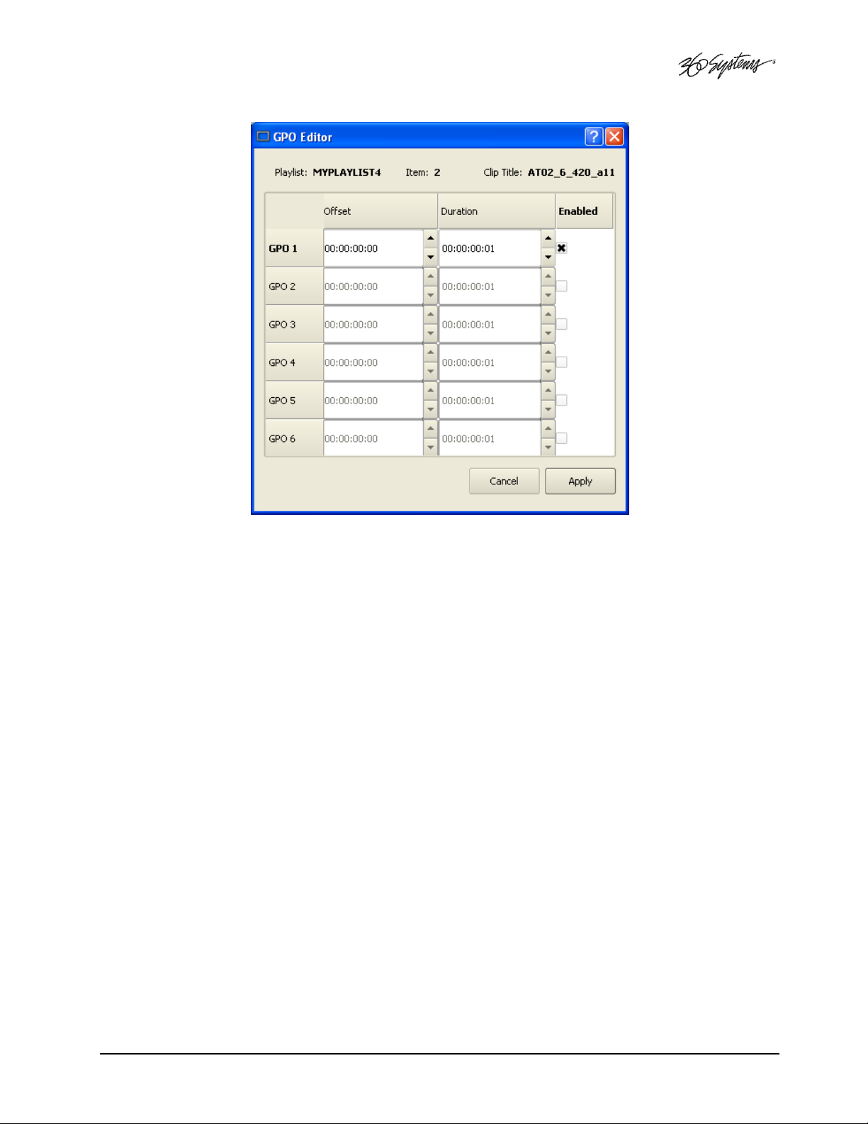
Figure 24 - GPO Editor
Mapping GPI to Control a Playlist
Playlists can be controlled with the Six GPI Inputs as described in Programming GPIO Inputs
on page 47.
MAXX Owner’s Manual Page 67
Page 68

Advanced Topics
System Timing
The Image Server is capable of using an external genlock signal as a timing reference. This allows
the outputs to be timed the same as other video signals in a facility. There are three adjustments to
fine tune this synchronization to compensate for differences in equipment and wiring. Genlock
LINES and SUBPELS set the sync relationship of all of the outputs to the incoming reference. Color
timing is adjustable for each channel independently with the SC/H PHASE setting.
These settings should be made in the following order:
1. Genlock Lines: This is a global setting for all of the outputs. It rarely ever needs to be
adjusted. It allows the output timing to be varied by a line of video. This would be
adjusted so that the output of the first line of video happens concurrently with other
contributing inputs. The visible effect is that the picture will rise or fall by one line when
viewed at the output of a video switcher or on a genlocked monitor. Note that this setting
can cause vbi lines such as Closed Captioning and VITC to appear on different (and
possibly inappropriate) lines.
2. Genlock Subpels: This is a global setting for all outputs. It allows the output timing to be
adjusted by half a pixel. The visible effect is that the picture will move horizontally when
viewed at the output of a video switcher or genlocked monitor. The adjustment is made
by using a waveform monitor and comparing the falling edge of horizontal sync between
the output and another contributing signal (not the genlock signal.) Some video switchers
indicate when a signal is timed within spec; this can be used to determine when the
setting is correct. If correct system timing is indicated over a range of subpel settings,
determine the extreme of the range and set the value in the middle.
3. SC/H Phase: This is a setting per channel, found in the Transport>Options>Configure
menu (it does not appear in the Playlist’s Options menu.) The adjustment is made by
using a vector scope display referenced to the color reference, usually the genlock signal.
Play back the zCBARS clip. Adjust the SC/H PHASE to align the color with the vector
scope points. Note that it is normal to see some slight periodic variation in the vector
display.
Page 68 MAXX Owner’s Manual
Page 69

Using Embedded Audio
Embedded Audio is standard equipment on MAXX. It is based on SMPTE standard 272M-A. Key
features include:
• Synchronous 20-bit audio at a 48K sample rate. Non-synchronous audio and other sampling
rates are not supported.
• While up to 16 channels of audio may be present in an SDI stream (arranged in 4 groups of 4
channels), the Image Server records and plays back only Group 1 audio channels (channels 1-4).
• In E-E mode, all embedded audio will pass through the Image Server unaltered.
• The user can select audio to record from either a +4 analog, AES/EBU digital, or embedded
audio source. Mix-and-match among inputs is not supported.
• Embedded audio is always included in the SDI stream on playback, and audio will
simultaneously appear on the AES/EBU or analog audio outputs, as selected by the audio card
option jumpers. When analog audio is selected, only channels 1 & 2 will be available at the
analog output. Embedded channels 3 and 4 are not affected.
• User bits in the SDI embedded audio stream are not supported.
• 20 bit Dolby E is supported
Configuring Embedded Audio
From the GUI window, click OPTIONS->CONFIGURE from the Transport View of Channel 1.
The Channel Configuration window shown below will appear. Use this window to configure
Embedded Audio.
Figure 25 - Channel Configuration Screen
MAXX Owner’s Manual Page 69
Page 70

Setting the Input Source
Three buttons select the input source for video and audio. These are:
• CVBS/Discrete Audio (composite video with AES/EBU or analog audio inputs)
• SDI/Discrete Audio (serial digital video with AES/EBU or analog audio inputs)
• SDI/Embedded Audio (serial digital video with embedded audio)
The discrete audio inputs can be either: two stereo pairs (4 channels) of AES/EBU digital audio, or
one stereo pair of +4dBu analog inputs, as determined by jumpers on the audio card.
Regardless of the input selected, audio will always appear in the SDI output stream as embedded
audio, and at the discrete outputs as either AES/EBU (digital) or as +4 dBu balanced analog audio.
The Image Server supports Group 1 embedded audio, which includes audio channels 1-4, 20-bit,
48 KHz, synchronous audio, as per SMPTE 272A.
The analog audio channels always input to and output from channels 1 and 2. Audio channels 1,
2, 3 & 4 always correspond to their like-numbered Group 1 Embedded Audio channels.
Note: When recording SDI, the SDI signal must be synchronous with genlock.
Using Audio Sample Rate Conversion
Two check-boxes are provided to engage built-in sample rate converters for either (or both) of
audio channel pairs 1 & 2, and 3 & 4. When checked, the incoming AES/EBU audio tracks are
converted to a 48K broadcast standard synchronized by video genlock.
The sample rate converters should be used in any of these cases:
1. The incoming digital audio and video are not referenced to the genlock.
2. The sync reference is set to INTERNAL.
3. The incoming digital audio is not at 48 KHz sample rate.
Note: Audio sample rate conversion is not applicable for Embedded Audio and Audio Rate
Conversion boxes will be grayed-out if the SDI/ Embedded audio check-box is selected, or if the
XLR audio inputs are jumpered for analog audio.
Page 70 MAXX Owner’s Manual
Page 71

Using Channel Ganging
Transport operations on Video Channels can be locked or “ganged” together to allow frameaccurate key and fill material (either stills or clips) to be implemented. Channel Ganging might also
be used to create certain types of presentations, such as synchronized matte backdrops on News
Broadcasts.
The channels can be ganged in the following combinations:
1. Channel 1 controls Channel 2
2. Channel 1 controls Channels 2 and 3
3. Channel 2 controls Channel 3
To configure Channel Ganging Click EDIT->CONFIGURE->TIMING from the Main Menu. The
screen of Figure 26 is displayed.
To select Channel 1 to be ganged with channel 2 only, set CHANNEL GANGING MASTER to 1
and click the GANG checkbox on channel 2.
To select Channel 1 to be ganged with channel 3 only, set CHANNEL GANGING MASTER to 1
and click the GANG checkbox on channel 3.
To select Channel 1 to be ganged with channel 2 and 3, set CHANNEL GANGING MASTER to 1
and click the GANG checkboxes on channel 2 and channel 3.
To select Channel 2 to control channel 3 set CHANNEL GANGING MASTER to 2 and click the
GANG checkbox on channel 3.
Figure 26 - Timing Configuration Screen
MAXX Owner’s Manual Page 71
Page 72

Using Ganging for Key and Fill operations
Channel Ganging is most commonly used to support and Key and Fill operations. Ganging allows
generation of frame-accurate key and fill material (either stills or clips). This in turn is used with a
downstream keyer or video effects generator to be externally combined with a third video source.
Manual or automation control of the Master channel is all that is needed to play both the key and
the fill.
Key and fill clips are associated by their names. The Key Clip must have the same name as the Fill
Clip with a trailing underscore. Example:
Fill clip name: myfile
Key clip name: myfile_
There is no provision for automatic loading of similar named clips on more than two channels - the
Master channel and the next higher numbered Ganged channel. Additional channels must be
loaded manually, after loading the master channel.
Proper key and fill operation requires two clips of identical length. This can be accomplished by
editing with head and tail trim. Long GOP mpeg clips should not be used if editing will be
required to allow precise head point positioning.
Channel 2 is ganged to Channel 3 in the following example.
When a clip is opened/cued on Channel 2, Image Server automatically looks for another clip with
the same name, plus a trailing underscore. If the clip is found, it is loaded on Channel 3. The
Channel 2 clip contains the “fill” material, while the Channel 3 clip has the “key” (or alpha) file.
An automation system, could, for example, issue a VDCP Cue command to Channel 2 for a clip
called “logo”. Channel 3 would automatically be loaded with clip “logo_”. A Still or Play
command sent to Channel 2 would cause both Channels 2 and 3 to display the fill and key clips,
respectively.
Note that the VDCP checkbox option to “show first frame” for a Cue command is ignored for
channels in ganged mode. The automation system must issue a Still command to Channel 2 to
achieve this effect.
Ingesting a TARGA file via FTP automatically creates a key clip and a fill clip, each a single frame
in length. For example, if file “xyz.tga” is transferred to an Image Server via FTP, then a pair of
single-frame clips is created: “xyz” and “xyz_” containing the fill and key material.
Using DV Video and Graphics
Playback of DV-format video and TARGA Graphics is included. It plays DV-25 files in native
format, and TARGA graphics files including those with key and fill. DV and Graphics enables
direct FTP import from Photoshop®, After Effects®, Final Cut Pro®, Xpress DV/Pro™, Liquid Edition
and Vegas video.
With DV and Graphics, Image Servers are able to function as both a graphics still-store and an
animation playout server. Its three simultaneous outputs give it the power to combine video,
graphics and animation playback. Channels can be ganged in various combinations to provide keyand-fill playout, while Channel 1 plays background video. The following capabilities are included:
Page 72 MAXX Owner’s Manual
Page 73

Importing TARGA Graphics Files
The Image Server will recognize and ingest single-frame TARGA files via FTP from most networkattached graphics workstations. TARGA files have a .tga extension, and may contain an alpha (or
key) channel. During transfer, the Image Server will split the TARGA file into a Fill frame, and a
Key frame if it exists. These will be converted to high-resolution MPEG-2 files, one frame in length.
For example, if an original file is named Logo.tga, the MPEG-2 files created will be named
Logo.mxf (the fill file) and Logo_.mxf (the key file). Note the trailing underscore “_” added to the
file name of the key. This allows the TARGA file to be used for key and fill applications when
channels 2 and 3 are ganged together.
Once a TARGA file is ingested, it exists only as an MXF MPEG-2 file. The processed file may be
transferred to-and-from network-attached storage, another Image Server, or a graphics workstation,
as two separate MXF MPEG-2 files.
The resolution of a TARGA image should be 720 x 480 for NTSC video or 720 x 576 for PAL. If
the original TARGA image is not of this resolution, the Image Server will re-scale it, possibly
introducing some dimensional distortion. The bit depth of the files must be 24 or 32 bit. The
Image Server does not support Targa sequences, only single frame graphics.
Animation Import
From the Image Server’s standpoint, an “animation” is a clip with a minimum length of two
seconds. Clips used in back to back seamless playback must be a minimum of four seconds long. A
separate Alpha channel may or may not be present. Any graphics workstation capable of exporting
files supported by the Image Server can make transfers to it via FTP. If an alpha channel is present,
the naming conventions of the Key/Fill Mode apply: the file name for the key video is the same as
the filename for the fill video with the addition of an underscore character ( _ ). Many software
programs have the ability to create content compatible with the Image Server , including Final Cut
Pro® 4, Avid® DV Xpress, DV/Pro, Liquid Edition, Vegas video, and Adobe® After Effects®,
Premiere® and Photoshop®.
Still Frames
A single-frame clip (a “still”) may be inserted into a playlist. The length of a still will appear as one
frame in the clip list. When a still is encountered, the playlist will pause and hold the still image
until a Play command is issued, at which point the playlist will continue to the next clip in the list.
When using the GUI, the space bar (a keyboard shortcut) will also advance the playlist. Stills may
be placed anywhere in a playlist. In fact, a playlist may be entirely composed of stills.
A still frame clip in a playlist can have a duration assigned to it (See page 65 ). It will then play for
that duration and the list will continue automatically.
Stills are created when TARGA files are ingested. (See page 77 for a description of TARGA file
ingest.) It is also possible to create still frames from video clips that use a 1 frame GOP (I-frame
only.) When editing the clip, make the In and Out points the same frame. This frame will be
displayed when the clip is played in the Playlist.
MAXX Owner’s Manual Page 73
Page 74

FTP File Transfers
Image Server features Gigabit Ethernet connectivity using an RFC-1359 compliant FTP server. File
transfers to and from the Image Server are managed from an FTP client file transfer program
running on a Windows® or Macintosh® computer. This provides a rapid way to execute drag-anddrop file transfers; it can also manage many Image Servers at once and does not tie up the Image
Server GUI, which may already be in use.
FTP Client Version Platform
Flash FXP 3.2.0 WINDOWS XP, WIN2K
DOS FTP 5.1.2600 WINDOWS XP, WIN2K
WS FTP 5.08 WINDOWS XP, WIN2K
Internet Explorer 6.0.2900 WINDOWS XP, WIN2K
Fetch 5.2 MAC OSX
CyberDuck 2.7.3 MAC OSX
Table 2 - Supported FTP Clients
FTP programs may also be used to move recorded or edited material between an Image Server and
Network Attached Storage (NAS) or a DVD-ROM library.
From a networking or system-integration viewpoint, the Image Server appears as a normal FTP
server in any size network, with the exception that it may only send, receive, or store video files
that are compatible with the Image Server.
Table 2
indicates the supported FPT client list.
The Image Server is designed to be used in a private dedicated video network. A firewall
must be used in systems that require internal security or connection to public networks.
Consult with a network security specialist for guidance on the best hardware,
programming and practices for your facility’s requirements.
Gigabit Ethernet Cable Quality
The high data rates generated by Gigabit Ethernet require high-quality cable designed for this
application. Low-quality network cables can result in high error rates and lower transmission
speed. For Gigabit operation, standard CAT-5 cable should be used only for very short cable runs.
New Category 5e (enhanced) cables ensure maximum transfer rates, and should be used as the
minimum standard. Category 6 cable is a more recent product designed for applications where
longer cable runs are required.
Configuring the FTP interface
Before logging in to the Image Server’s FTP server, the network must be configured according to
the local network topology. This is primarily a matter of setting a static IP address or configuring
MAXX to use DHCP to obtain an IP address from a DHCP server. Refer to page 48 for details on
configuring the network settings.
Page 74 MAXX Owner’s Manual
Page 75

If you will be connecting directly to a PC or Laptop, configure the Image Server as IP address
192.168.1.3, netmask 255.255.255.0 and disable DHCP. In the PC, double click on the Local
Area Connection Icon in the system tray or in the Network and Dial-Up Connections in the Control
Panel. In the Local Area Connection Status dialog, click on Properties. Click on the item “Internet
Protocol (TCP/IP)” and click on Properties again. In Local Area Connection Properties, turn off
“Obtain an IP Address Automatically“ by selecting “Use the Following IP Address” and set the
address to 192.168.1.2, netmask to 255.255.255.0.
No hardware settings are available or needed. The NET
NET----1111 port automatically negotiates port speed
NETNET
and configures transmit and receive connections, and does not need a “crossover” cable when
connecting directly to a PC.
The actual transfer rate depends on the format of the files being transferred, the number and bit rate
of video streams being played. In practice, broadcast content encoded at 12 Mb/sec should
transfer at a rate five times faster than real time, even while the server is playing video.
Logging in to the Image Server FTP Service
The Image Server allows only for anonymous login. Using one of the FTP clients shown in Table 2,
enter “anonymous” as the user name or check the “anonymous” checkbox on the login screen.
When the FTP client is connected, it will display the Clips in the main directory and all of the subfolders. Clips can be uploaded, downloaded, deleted and renamed using standard FTP client
commands. Clips in the subfolders can be displayed by entering those folders. Consult the
documentation for your FTP client for information on changing folders.
The Image Server will support two simultaneous data transfers (2 in, 1 in and 1 out or 2
out.) There can be up to two additional FTP sessions active for other purposes such as
viewing the directory.
File Sizes Reported in Listing
The size of a clip reported in the file listing is the amount of video and audio data included
between the In/Out points.
Overwriting Files
It is the responsibility of the client application (Windows Explorer, FlashFXP, etc) to ask the user if
they want to overwrite a file.
Note that some types of files (such as .avi and Targa) change their file extensions when they have
been transferred into the Image Server. In these cases, the FTP client cannot warn of a file
overwrite. It is important to take extra care when using these types of files not to overwrite
necessary files.
Interrupted and Resumed Transfers
If a transfer is interrupted (for example, by a dropped connection) the amount of the file that has
been transferred is kept on the target system. Resumption of a partial transfer is possible if the FTP
client supports it.
MAXX Owner’s Manual Page 75
Page 76

01:22:18;04
00:30:00;00
(
)
00:32:00;00
(
)
00:30:00;00
00:32:00;00
Transfer of Edited Segments
The Image Server sets MARK-IN and MARK-OUT points in a clip as “edit pointers.” For all edit
operations within a given Image Server, these pointers produce “virtual edits” that save disk space,
and the time it would take to re-write the marked region as a new file.
It is clearly impractical to transfer a long file to obtain a 30-second virtual clip marked within it.
Therefore, the Image Server transfers only the region between In/Out points, and not the entire file.
If you want to transfer the entire recording, be sure that the In/Out markers are set to the beginning
and end of material before the transfer.
To maintain the identity of the transferred clip, the time code references for its Mark-In/Out points
are maintained, as shown in
segments of edited DV format clips will start at 00:00:00 after being transferred.)
When transferring edited material, keep in mind that you are making copies of the data on the
target device. While subclips that reference the same video content on the original recordings take
up minimal extra disk space, they could take considerably more space on the target storage.
Figure 27
Before Transfer (On Source Image Server)
CLIP_A.mxf
. (Note that DV files do not contain a start time, so all
IN POINT
After Transfer (On Target Image Server)
CLIP_A.mxf
OUT POINT
Figure 27 – Result of a network file transfer
Supported file types
MAXX recognizes media file types by their file extension. It is important that the file extension
properly identifies the file content. Attempts to send a file in one format but masquerading as
another due to a wrong file extension may result in undefined behavior. The following formats are
supported:
MXF - Material Exchange Format (.mxf)
The Image Server supports FTP import and export of MPEG-2 files in MXF format conforming to
operational pattern 1A. The video essence must be a standard-definition (NTSC or PAL) MPEG-2
elementary stream, including D10. The audio essence must contain 16 or 24 bit samples, sampled
at 48000 Hz, organized as a single track containing 1, 2 or 4 audio channels. Applicable standards
are SMPTE 377M, 378M and 381M.
Page 76 MAXX Owner’s Manual
Page 77

DV Stream (.dv)
The Image Server recognizes DV25 (25 Mb/s) stream files containing multiplexed video and audio
according to SMPTE 314M. The audio must be 48 KHz sample rate locked to video. The .dv file
extension is maintained, allowing transfer of .dv files between Image Servers and graphic
workstations without modification. DV50 is not supported.
AVI Files in DV format (.avi)
An AVI file is a container that encapsulates a wide range of audio and video formats. The Image
Server can recognize only DV AVI Type 1 and Type 2. Type 1 .avi files contain a single stream of
multiplexed audio and DV25 format video as described above. Type 2 .avi files contain separate
audio and video (even though the video may contain the same or different audio interleaved.)
During ingest of .avi files, the server will convert the file into a DV stream (.dv) for storage and
future FTP transfer. When the resulting .dv file is exported, if it was originally a type 2 it will
contain the .avi audio, not any audio that may have been present in the DV video stream.
MPEG-2 Program Stream (.mpg, .std)
Standard-definition MPEG-2 program streams containing up to 2 stereo pairs of 16-bit, 48K,
MPEG2 Layer 1 audio are supported. 16-bit audio files will be written into a 24-bit space.
TARGA (.tga)
24 or 32 bit format (16 bit format is not supported.) During transfer, the TARGA file will be split
into a Fill frame and a Key (Alpha) frame. These are saved as two separate MPEG-2 clips, each one
frame in length. The clip name for the fill frame is the base name of the .tga file, while the key
frame has this name with an appended underscore character. The resulting files will be available as
MXF files for subsequent FTP transfer.
PES – Packetized MPEG-2 Elementary Stream (.mp2, .m2v)
The Image Server will accept MPEG-2 standard-definition elementary stream files. These contain
video-only, no audio.
Wave (.wav) or Wave-64 (.w64)
The Image Server will accept WAVE or WAVE-64 files containing only audio. Audio files should
contain 24-bit stereo pairs sampled at 48 KHz. The resulting audio-only clips are available for play
out, but do not appear in the FTP directory listing for subsequent transfers.
Playlists (.lst, .txt)
An Image Server play list is a text-based file residing in the /lists directory. Play lists can be created
off-line and transferred to the Image Server using FTP. See page 132 for further information on
Playlist file editing and management.
As-Run Logs (.arl)
As-Run logs are available from FTP to confirm the operation of the Image Server Advanced Playlist
feature. See page 63 for further information on using As-Run logs.
MAXX Owner’s Manual Page 77
Page 78

Network Time Protocol
Automatic Date/Time Updates
When using Image Server play-lists in broadcast applications, an accurate record is often needed of
what was played and when. The Image Server’s As-Run logging feature creates such a record, time
stamping each played clip using the machine’s internal date/time clock. Very accurate time
stamping can be achieved by synchronizing the server’s clock to an external time base that is
referenced to Coordinated Universal Time (UTC).
This is accomplished using the Network Time Protocol (NTP) to interrogate time servers through a
network connection. A time server could be an in-house computer that is equipped with a GPS
receiver, or a radio receiver locked to signals from the NIST radio station WWV. Alternatively,
public time servers may be used which are accessible through an Internet connection.
Connecting to the Network
To obtain automatic date/time updates from the public time servers on the Internet, you will need
to provide the Image Server with Internet access. Generally, Image Servers would be connected on
a secure high-speed local area network, with any Internet connection going through a router with
an integrated firewall. The Network Time Protocol uses TCP/IP port number 123, so be sure the
firewall is configured to allow access to this port per Figure 28.
Figure 28 - NTP Network Block Diagram
Page 78 MAXX Owner’s Manual
Page 79

Configuring NTP
The Image Server GUI is used to set the time zone and to enter the networking parameters. The
local GUI must be used, as these configuration screens are not available on the Remote
Workstation Interface.
Selecting the Time Zone
Starting at the main menu bar, Click Edit->Configure->Date-Time screen. When “Automatic
Updates” is not checked, the Region and Zone lists are enabled. Select your region and then the
zone within that region. There may be more than one way to your zone; America/New_York, for
example, is the same as US/Eastern. Click the APPLY button to activate the settings,
After changing the time zone, you must perform at least a Quick Restart before the changes
become fully effective.
Figure 29 - Date/Time Configuration Screen
MAXX Owner’s Manual Page 79
Page 80

Entering Network Parameters
From the GUI’s main menu bar, Click EDIT>CONFIGURE>NETWORK. The screen of below
appears. Make sure the basic network parameters have been entered.
Figure 30 - Network Configuration Screen
Disable Network: uncheck
Host Name: (Any name will suffice, but since this name appears on each line of the Image Server’s
diagnostic logs, it is a good idea to keep this short.) The name should also be unique from other
devices on the network.
If “Use DHCP” if not checked, then enter a fixed IP address compatible with your local subnet. For
example,
IP Address: 192.168.1.20
Net Mask: 255.255.255.0
Default Router: 192.168.1.1
The Name Servers and NTP Servers fields provide the information needed to reach the public time
servers.
The NTP Servers field contains a list of time servers, either by numeric IP address, or by site name
(URL). Entries are separated by spaces.
Page 80 MAXX Owner’s Manual
Page 81

The nonprofit Internet Systems Consortium, Inc. (ISC) maintains sites that automatically return lists
of public time servers to an NTP client such as the Image Server. Hence, the NTP Servers field is
initially filled in with the URL’s for these sites (0.pool.ntp.org, for example). Of course you can
overwrite this list with the addresses of specific time servers you may want to use. However, if you
try to clear the NTP Servers field it will be reset to the default list.
Note: When URLs (non-numeric site address such as pool.ntp.org) are used in the NTP Servers
field, you must provide the IP address of at least one DNS (Domain Name Server) in the Name
Servers field. Typically, this address is supplied by your Internet Service Provider.
These name servers translate URL names into numeric IP addresses needed to access the sites in
question.
If you are using a GPS-based time server for instance, that is connected directly to your local area
network, enter its numeric IP address (such as 192.168.1.60) into the NTP Servers field, leaving the
Name Servers field blank.
Also, if you know the numeric IP addresses of the public or corporate time servers on the Internet,
you can enter these addresses, separated by spaces, in the NTP Servers field, leaving the Name
Servers field blank, since there would be no URLs to be resolved.
Note: Not all Time Servers allow unlimited public access. Refer to www.ntp.org for more
information.
Click the APPLY button to save your changes.
MAXX Owner’s Manual Page 81
Page 82

PLA
PLA
LAY
CH1 CH2 CH3
Automation Control
MAXX provides standard RS-422 serial control ports that allow operation with many broadcast
automation systems, instant replay panels, video switchers, and remote control devices.
For compatibility with simple controllers and push buttons, the server also provides six GPI
(contact closure) inputs, and six programmable-command outputs.
Remote Serial Control
The Image Server’s three 9-pin serial control ports permit independent control of its three video
channels. MAXX supports the following serial protocols.
1. VDCP
2. SONY BVW ( 9-pin )
3. ODETICS Extension to the SONY BVW ( 9 pin ) protocol
CH
CH
3
Y
100 - 240 VOLTS, 50 - 60Hz, 2 AMPS MAX
1
CH
RE
2
C/P
Y
Figure 31- Rear Panel Detail of Serial Ports
CH1 - RS-422 Control Channel 1, also referred to as COM1
CH2 - RS-422 Control Channel 2, also referred to as COM2
CH3 - RS-422 Control Channel 3, also referred to as COM3
When using VDCP, Each port can also respond to channel ID numbers that are equal to, or
multiples of, its base number. For example, channel 1 will also respond to 4, 7, 10, etc. This can
be helpful when an automation system needs to control a number of Image Servers at once
The server’s multiple serial ports allow simultaneous connection of an automation controller and
a desktop editing controller. This way, one could configure an edit controller on Channel 1 for
record, playout, and editing; while an automation controller on Channel 2 manages play-to-air
operations. Alternatively, a single controller could control the operation of all Image Server
channels.
It is also possible for a single VDCP controller to control multiple Image Server channels.
Page 82 MAXX Owner’s Manual
Page 83

Controller Priority
Only one serial controller can control a given video channel at a time. In general, the first
controller to gain control of a video channel will have exclusive command. This prevents
conflicting instructions that would cause unexpected behavior. The only exception is that the
graphic user interface can immediately take control of a channel by selecting Serial Control in that
channel’s dialog window.
External controllers are prohibited from taking control away from the GUI, the SERIAL CONTROL
mode must be checked in the channel dialog window before a remote control device can
communicate with that channel.
Configuring the automation interface
Setting the automation protocol for a video channel
Each of the three video channels can be configured independently for one of the following
protocols.
1. VDCP
2. SONY BVW
3. ODETICS
To map a protocol to a channel, Click EDIT->CONFIGURE->SERIAL PORTS from the main
pull-down menu. The screen of in Figure 32 is displayed. Use the PORT pulldown to select
COM1, 2 or 3. These map to Video channels 1, 2 and 3.
• Select VDCP to map the port to VDCP protocol
• Select BVW to map the port to SONY BVW protocol
• Select BVW to map the port to ODETICS protocol
NOTE:
VDCP operation can allow control of a channel by ID number from a different
numbered serial port, while BVW and Odetics protocol control only the channel
number corresponding to the number of the serial port in use. Take care if using
both protocols not to allow VDCP controllers to address a channel that is controlled
by BVW/Odetics on another serial port.
If necessary turn on “Assigned Serial Ports” in VDCP Options – this will force VDCP
to control the channel corresponding to the serial port it is connected to regardless
of the channel ID in the control messages.
MAXX Owner’s Manual Page 83
Page 84

Figure 32 - Serial Port Configuration Screen
Other Automation Options
As illustrated in Figure 32, a number of check boxes are provided that control how the Image
Server will respond to certain VDCP commands. Once set, these options remain selected when
the server is turned off, and until changed by the user.
NOTE: The following options will apply to all three video channels. They cannot be individually
configured for each video channel.
Cue Shows 1st Frame
Upon receiving a Cue With Data or a Play Cue command, the server will cue the clip then jog to
and display the first frame of video. (This also applies to Odetics protocol.)
Cue with Offset (vs. Timestamp)
When checked, the time code for the clip becomes “zero-based” with reference to the head
point. To move to the head point of the clip, the automation controller would send a time code
value of 00:00:00:00, regardless of the clip’s original time stamp. When unchecked, the Image
Server will calculate time code position based upon the time stamp from the first frame of the
unedited clip. Note that this only affects the operation of the serial port, it does not change the
way the Image Server displays time code in the GUI.
Vari-Play 1X Equals Play
The Image Server will interpret a Vari-play 1x command as a Play command. (This also applies to
Odetics protocol.)
Page 84 MAXX Owner’s Manual
Page 85

Vari-Play 0 Equals Pause
The Image Server will interpret a Vari-play 0x command as a Pause command. (This also applies
to Odetics protocol.)
Report Play (vs Still) At End
When the end of a clip is reached, the Image Server will report Play to the automation controller,
instead of Still.
Ignore Preroll Commands
A minimum 10-frame pre-roll is required to allow the server time to respond to serial commands.
See the documentation for your controller or automation to find out how to set the preroll value.
Due to variations in the way preroll commands are implemented in various systems, it may be
sufficient to check this box only. The setting of 10 frames in the controller will then work correctly.
This option is very seldom used, it allows preroll commands to be ignored and assumes that the
operational preroll is 10 frames. Do not check this unless you experience problems with frame
accuracy on recordings and playback transitions. Start with a setting of 10 frames on the
automation system and adjust until you achieve proper timing.
Auto E-E
Toggles Auto E-E mode (input monitor) on/off.
Assigned Serial Ports
VDCP protocol provides for altering the mapping of Serial Port to Video Channel via
control commands. Checking this option will lock the Serial Port to Video Channel
ordering.
• When checked, any command received on a particular serial port will be used to
control the like numbered video channel. This means that automation systems that
use fixed or limited VDCP ID numbers can use any output to control any channel of
the Image Server.
• With this option checked, there is no requirement for a Port Open command to
allow the automation to control the channel. With some systems, this can negate
the requirement to restart the automation system when bringing the Image Server
online.
• Do not check this option when using controllers that communicate with all
channels over a single serial port, such as Leightronix ® TCD/IP.
Communication Port Parameters
The serial data transfer parameters for the Image Server are fixed and cannot be changed. These
characteristics are common to all automation controllers:
Baud Rate 38.4 K Baud
Start Bits 1
Data Bits 8
Parity Odd
Stop Bits 1
MAXX Owner’s Manual Page 85
Page 86

Tested Automation Controllers
The Image Server has been tested by 360 Systems and the manufacturers of equipment listed
below, and found to operate correctly. This list is not comprehensive, and the inclusion or
absence of a product does not indicate a preference for any make or model. Operational variations
do exist between makes and models.
Manufacturer Controller Protocol Notes
H
ARRIS AUTOMATION
S
UNDANCE
NV
C
RISPIN CORP
F
VCI S
OLUTIONS
L
EIGHTRONIX
T
IGHTROPE MEDIA
H
P
EBBLE BEACH SYSTEMS
PROBEL M
P
T
HOMSON-PARKERVISION
ERZION
LORICAL
ARDATA
I
BIS
ITA
HAROS
A
VECO
ADC-100 VDCP
F
EMC-
. S
A
(DTG) A
TCD/IP VDCP
C
A
P
A
PVTV-P
AST BREAK
YSTEM
IR BOSS
ABLECAST
HDX
NEMONE
ORPHEUS
LAYTIME
VDCP
NT
VDCP
2000 VDCP
VDCP
IRO
VDCP
O
VIDEO O
STRA
LUS NEWS
VDCP A
DETICS
DETICS
VDCP
VDCP
VDCP
VDCP
VDCP
ALL HARRIS CONTROLLERS SAME
LL CR SERIES
Tested Remote Control Panels and Switchers
The Image Server has been tested by 360 Systems and manufacturers of the remote control
devices and video switchers listed below, and found to operate correctly.
Manufacturer Controller Protocol Notes
R
OSS VIDEO
E
CHOLAB
DNF C
ONTROLS
DNF C
ONTROLS
A
SH VALE
BUF VTC-4000 P2
BUF S
L
ANCE DESIGNS
HI-T
ECH SYSTEMS
S
O
YNERGY® SWITCHERS
PERA SWITCHERS
VDCP
VDCP
4000-CL VDCP
300-SSM P2
SM-2 P2
POT
VDCP
TDC-100 O
A
CTIV CART BOX
VDCP
DETICS
ALSO USED WITH DNF SHOT BOX
BVW
-75,
ALSO ODETICS PROTOCOL
SLOW MOTION CONTROLLER
BVW
-75,
ALSO ODETICS PROTOCOL
ALSO ODETICS PROTOCOL
U
ALL VDCP PRODUCTS SAME
SE
INT
MODE
Page 86 MAXX Owner’s Manual
Page 87

Remote Workstation Interface
The Image Server Remote Workstation Interface is a software application that provides IP control
of the server from PC workstations located within a facility.
A remote workstation can access one or more video channels of an Image Server to perform
ingest, playback, trimming, playlisting, traffic operations or monitoring of server activities.
Applications include—
• Control of an Image Server located in a machine room
• Ingest station for loading commercials and other content from tape
• Edit station for trimming content
• Building, editing and running playlists
• Remote control of an Image Server located at a transmitter site (“evergreen” backup)
• Access to file content and operations by engineering or management
• Control of more than one Image Server from a single workstation
• On a wireless network, an Image Server can be controlled by a secure
Wi-Fi enabled laptop computer
• Remote control in a conference room, or during auditorium presentations
• Image Servers may be securely controlled from a remote location, even across public Internet
connections, with inexpensive VPN (Virtual Private Network) technology.
A single Image Server may be controlled from many remote workstations, at different locations on
the network. See Figure 33.
Similarly, a single computer can run multiple Remote Workstations to control multiple Image
Servers.
Remote Workstation provides the same functionality as the local GUI with the following
exceptions:
• Remote Workstation cannot access the servers Network configuration screen
• Remote Workstation cannot shutdown the server.
• Remote Workstation cannot access the RAID status display
• Remote Workstation cannot display MAXX’s time-of-day clock.
MAXX Owner’s Manual Page 87
Page 88

Figure 33 - Remote Workstation Deployments
System Requirements
• PC with Windows XP or Windows 2000 installed. Other operating systems have not been
tested and as of this writing are not supported.
• 6 MB free space on the computer hard disk, plus 64 MB RAM.
About the Remote Workstation Interface
The Remote Workstation Interface consists of a CD-ROM carrying the Remote Workstation
application for Windows 2000 and Windows XP computers. It self-installs using the normal
Windows prompts.
It is possible to install the Remote Workstation software on a number of PCs; any of them can
then control an Image Server.
Operations
Up to three Remote Workstations can simultaneously view the channel activity of a single Image
Server. Only one Remote Workstation, however, can take control of a video channel at any given
time. Control of the Image Server video channel is not automatically granted to a Remote
Workstation just by attempting to use the GUI; control must be actively taken, using the TAKE
CONTROL option described below. This allows remote monitoring of Image Server channel
activity while greatly reducing the likelihood that a remote user will interfere with operations
initiated by another. All Workstations, including the Image Server’s local GUI, have equal priority
and any can take control of a video channel at any time. Control is granted for server channels
individually, and not automatically for all three; therefore, three Remote Workstations can each
control a separate video channel. Each Remote Workstation can display or close transport
windows without affecting other Workstations or the Local GUI.
Page 88 MAXX Owner’s Manual
Page 89

The IP address of a Remote Workstation currently controlling a channel appears in the status bar
on the bottom-left of the Playlist or Channel window.
A menu labeled Options appears at the upper-left of each Image Server channel window.
Clicking this menu presents a drop-down menu with a TAKE CONTROL option. Select this then
click Yes in the confirmation dialog to give control of the video channel to your workstation.
Installation
To install Remote Workstation software from CD-ROM:
• Insert the CD-ROM into the drive on a PC.
• The auto-run capability of Windows will start the Remote Workstation setup program. If it does
not, select the Run… option of the taskbar Start Menu and type: D:\setup.exe. If necessary,
replace D:\ with the drive letter of your CD-ROM.
• You will be prompted to enter the IP address of the Image Server you wish to control. If you
know the address, enter it here. This information can also be entered after installation.
• You will be asked to agree or disagree with the terms under which this software is licensed to
you. If you agree, installation will continue. If you do not agree, installation will stop. Follow
the prompts to finish installation.
• By default, the Remote Workstation software installs all required files into the
C:\Program Files\ Image Server RWI folder. However, during the installation process an
alternate directory may be specified. If a previous version of Remote Workstation is already
installed on the Host computer, use this feature to install the new version in a uniquely named
folder, for example C:\Program Files\ISMAXX.
After Installation
A 360 Systems Remote Workstation icon will appear on your desktop. Double click the icon to
open a remote session on the Image Server. To change the target Image Server you wish to access,
right click on the Remote Workstation icon. Select “Properties” from the drop-down menu. In the
“Target” text box, change the IP address listed in the box to the IP address of the Image Server and
select “OK” or “Apply.” Refer to Figure 34.
MAXX Owner’s Manual Page 89
Page 90

Figure 34 – Remote Workstation Properties Page
Because multiple simultaneous sessions of Remote Workstation may be run on a single, it is
possible to make copies of the Remote Workstation icon and change the IP address of each to
allow one-click access to any number of Image Servers. Simply right click on the Remote
Workstation icon and select Copy from the pop-up menu. Next, right click anywhere on the
desktop and select Paste. Finally, follow the instructions above to edit the IP address to match the
second Image Server.
Page 90 MAXX Owner’s Manual
Page 91
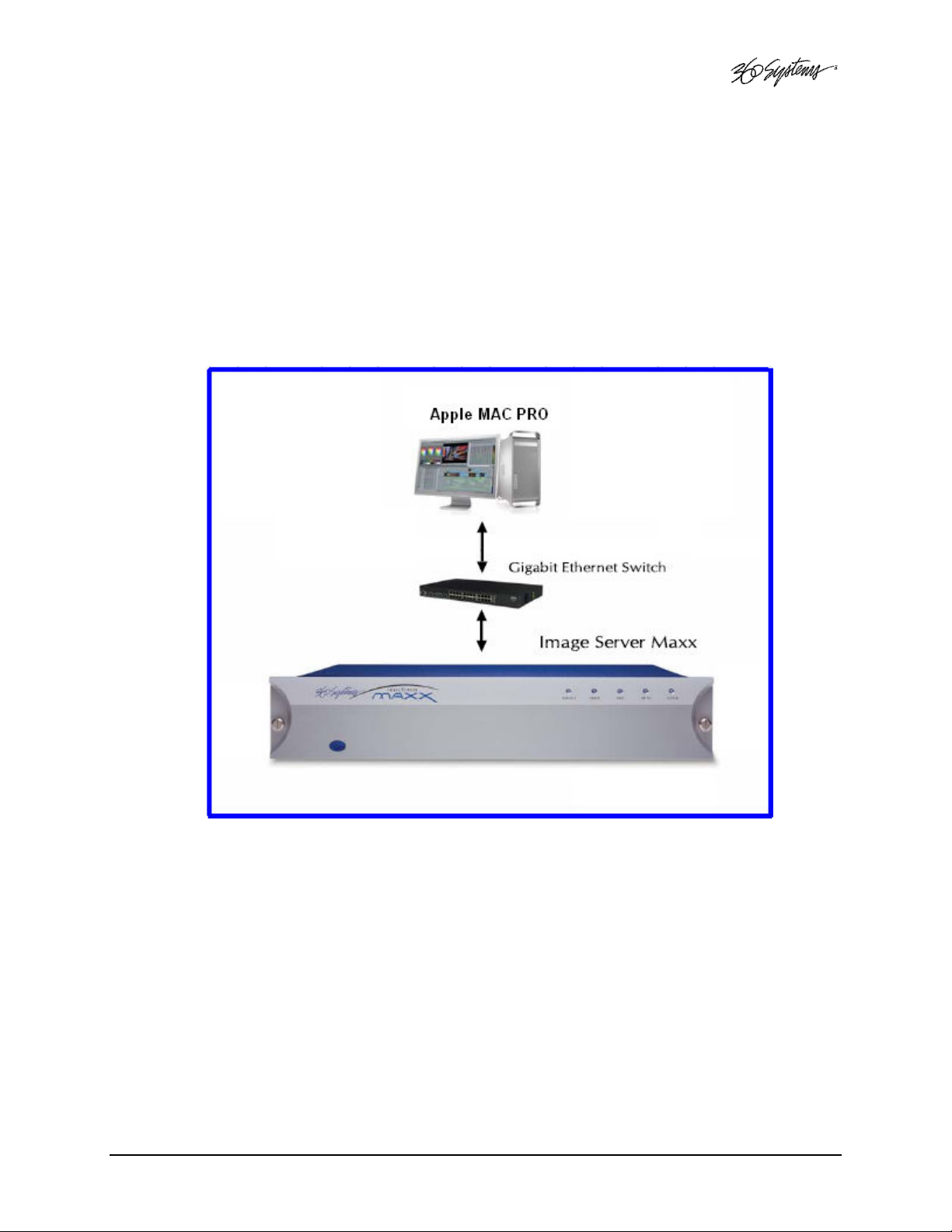
Using Image Server With Final Cut Pro
The Image Server IMX option coupled with Telestream’s Flip4Mac Image Server Component
provides a “round-trip” compatibility with Apple Final Cut PRO, providing the following capability:
• Record Industry Standard IMX Content.
• Export IMX clips to Final Cut PRO over Gigabit Ethernet using the Flip4Mac Image Server
Component Plug-in developed especially for Image Server.
• Edit IMX clips in Final Cut PRO.
• Export IMX clips back to Image Server for Playback.
Requirements
The following equipment is required to support Final Cut PRO interoperation:
1. Image Server MAXX with IMX Hardware Option 300-102-0024-01
2. Image Server software version 4.05.370 or later
3. Final Cut PRO software version 5.0.4 or later
4. Telestream Image Server Flip4MAC plug-in version 2.1.10.12
5. Apple Macintosh computer “MAC PRO” including:
a. Dual Core Xeon 2.66 GHz with
b. 1GB DDR2 RAM minimum.
c. NVIDIA GeForce 7300 GT graphics with 256MB memory
d. 250GB Serial ATA 3 GB/s 7200-rpm hard drive
MAXX Owner’s Manual Page 91
Page 92

Recording IMX Content
Image Server is capable of recording MPEG-2 material in SONY IMX format at 30, 40 or 50 Mb/s.
This format must be selected if material is to be edited in Final Cut PRO. Material recorded in Main
or 4:2:2 profiles cannot be edited on Final Cut Pro.
From the Configure Window –> Choose Channel 1
• Set the MPEG-2 Format to 4:2:2 IMX
• Set the Max Bit Rate to 30, 40 or 50 Mb/sec.
The use of 30 Mb/s is strongly recommended. The additional quality of 40 and 50 Mb/s in most
cases is not worth the extra disk storage space and transfer time required.
Image Server 2000, MAXX 250 and MAXX 400 units can play 2 channels of 40 or 50 Mb/s IMX.
• Select FILE>NEW from the channel 1 transport window
• Press RECORD to begin recording.
Transferring IMX Content from Image Server to Final Cut PRO
Start Final Cut PRO. Make sure you have installed the Telestream Image Server plug-in.
• Select File>Import>Image Server per Figure 1
Figure 1 – File Import Menu
Page 92 MAXX Owner’s Manual
Page 93

• A pop-up (Figure 2) prompts for the IP address, User Name and Password. Enter the IP
address in the designated field. Enter Anonymous for the User Name. Click on CONNECT
Figure 2 – Image Server Connect Screen
A list of files on the target Image Server will be displayed per Figure 3. Click the check box on the
file or files you want to import. Click the IMPORT button.
Figure 3 – Flip4Mac’s Image Server File List Screen
The file will upload. Load times will vary depending on data rate of the encoded material, the class
of MAC you are using and whether the Image Server is busy playing out to air. Here are some
examples of load times. In general, Import and Export times are symmetrical.
MAXX Owner’s Manual Page 93
Page 94

Clip Format Clip Duration Transfer Time - Idle Transfer Time - Playing Clips Playing
30 Mb/s IMX 60 seconds 49 Seconds 57 Seconds 3 – 30 Mb/s
40 Mb/s IMX 60 seconds 61 Seconds 63 Seconds 3 – 40 Mb/s
50 Mb/s IMX 60 seconds 70 Seconds 73 Seconds 3 – 50 Mb/s
Once the file is loaded it will appear as an icon that displays the first frame of the content and the
name of the clip. Before material can be edited, the sequence settings in Final Cut Pro must be set
to match the characteristics of the clip. This is important because if they do not match, Final Cut
PRO will attempt to render the entire cut before it can be edited. This is fairly quick on clips of one
or two minutes, but it can be unacceptably slow on longer clips.
Check the Characteristics of the clip
Mouse over the icon of the imported clip. Hold down the CTRL key and click on the icon. Select
Properties from the pull-down. Make a note of the properties. If you will continually edit the same
type of content you will not have to repeat this step.
Set the Sequence Settings to match the clip characteristics
Select Sequence->Settings.
Configure the settings to match the properties of the clip. Of particular significance is the
Compressor field. Here is an example of sequence settings for a 30 Mb/s IMX clip recorded on the
Image Server:
Property Setting for IMX @ 30Mb encoded on Image Server
Frame Size 720 X 486 720 X 576
Aspect Ratio NTSC – CCIR 601 (40:27) PAL – CCIR 601 (5:4)
Field Dominance Lower Lower
Editing Timebase 29.97 25
Compressor MPEG IMX 525/60 ( 30 Mb/s ) MPEG IMX 625/50 ( 30 Mb/s )
Audio Rate 48 KHz 48 KHz
Depth 16 bit 16 bit
The only difference in the settings for 40 Mb/s and 50 Mb/s clips is the compressor used should
match the bit rate.
NTSC PAL
Once the Sequence Settings have been configured, drag the icon of the clip down to the timeline.
If the settings are properly configured, a red line should not appear above the clip on the Timeline.
If a red line does appear, recheck the sequence settings and clip properties and repeat the step
above.
Editing Content in Final Cut PRO
Entire industries exist to educate and assist Final Cut PRO users. In summary, once the clip is on
the Timeline, the first frame will be displayed in one of the television-like sequence windows. If it
has been imported properly, you will be able to play it using the intuitive VCR-like controls in the
window. It is important to select and work only on a specific region that requires editing. If a
specific region is not selected, Final Cut PRO may render the entire clip every time you make a
change. The rendering process is quite time-consuming. Refer to relevant Final Cut PRO
documentation for tutorials.
Page 94 MAXX Owner’s Manual
Page 95

Exporting and Playing Content on the Image Server
Once content has been edited in Final Cut PRO, it can be re-exported back to the Image Server for
storage and playout as follows:
Select File->Export->Image Server per Figure 4
The same pop-up menu is displayed as for the file Import function. Enter the IP address of the
server and check ANONYMOUS login. The edited file will be exported via FTP to the server.
Figure 4 – File Export Screen
MAXX Owner’s Manual Page 95
Page 96

Hard Disk Management
Image Servers employ an advanced Serial-ATA controller that manages four high-capacity hard
disks operating in a RAID-5 configuration. This design increases system performance, and by
storing parity data, helps prevent data loss should a drive fail.
The Image Server brings a high level of reliability to Serial-ATA RAID through a new, switched
architecture that exceeds the reliability of SCSI shared-bus storage systems. The earlier shared-bus
architecture of SCSI has inherent performance limitations due to arbitration latency, since only one
drive may use the bus at a time. Further, a single drive failure can bring the entire storage system
down.
By contrast, the Image Server uses a non-blocking switched architecture to isolate the drives from
one another. Any drive failure makes that drive unavailable and the rest of the storage system
remains undisturbed. In addition, the Image Server uses Advanced Data Protection features, where
all drive commands are checked to ensure that no command corruption has taken place over the
entire data path.
Some of the Image Server RAID implementation features and benefits include:
• Non-blocking switch technology with RAID 5 parity
• On-board processor minimizes host CPU overhead
• Easy-to-configure arrays
• Dynamic sector repair for robust data protection
• Accelerated RAID-5 writes
• Easy drive replacement from front panel
About RAID 5
A RAID 5 configuration features the data striping of RAID 0, combined with the parity benefits of
RAID 4. Using a parity (exclusive OR) function, RAID 5 can tolerate the loss of one drive. Parity
information is distributed across all drives rather than being concentrated on a single disk. This
avoids throughput loss due to contention for the parity drive. Spare drives can be used to rebuild
an array after a drive is replaced.
RAID-5 capacity equals the size of drive times (number of drives -1). In addition, the array’s
storage efficiency increases with the number of disks; from 66.7 % for 3 drives to 75 % for 4
drives: storage efficiency = (number of drives -1) X (number of drives).
Page 96 MAXX Owner’s Manual
Page 97

RAID Level 5:
“Independent Access Array with Rotating Parity”
High Data Reliability & Transfer Capacity
DATA
Disk Array
Controller
Array Management Software
Provides Logical to Physical Mapping
1 2 3 P
4 5 P 6
7 P 9 8
P 10 11 12
Disk 2 Disk 1 Disk 0 Disk 3
Figure 21: RAID 5 Array Schematic
Physical
Improved Write Performance
The Image Server uses new designs to improve RAID-5 write performance for both large
sequential and small random transactions. This advanced block caching firmware delivers
extremely high performance for RAID-5 write operations.
Managing Disk Arrays
The Image Server’s Disk Array Configuration Utility provides tools for monitoring and
managing the disk array. Monitoring and troubleshooting programs automatically check the
array, report problems and provide access to RAID status information and service options.
A single drive fault should not cause data loss; but remember: the drive array is degraded and
no longer has storage redundancy. Hence, another disk failure may cause a complete loss of
data and system failure. After a drive failure it is strongly recommended that at the earliest time
diagnostics be performed, and the server be taken off line while the RAID array is rebuilt.
Error Notification and Repair
The Image Server will notify users in the event of a fault by flashing the front panel DRIVES
light. A flashing DRIVES
response to a flashing light is to open the RAID CHECK STATUS window from the On-Screen
Start Menu. Click Start > System > RAID Status to launch the Array Configuration Utility.
DRIVES light can be triggered by a variety of conditions. The first step in
DRIVESDRIVES
DRIVES
DRIVESDRIVES
MAXX Owner’s Manual Page 97
Page 98

The RAID Status window (Figure 23) displays the current status of the RAID controller and all
disks connected to the RAID system. On inspection, you will find the array in one of the
following states:
• OK, indicated by "OK" for Array Unit 0 and all Ports (drives);
• Initializing, indicated by "Initializing" on the Array Unit 0 status line;
• Degraded, indicated by "Degraded" on the Array Unit 0 status line;
• Rebuilding, indicated by "Rebuilding x%" on the Array Unit 0 status line.
“Rebuilding” is the process by which the array controller corrects data parity errors that may
have occurred because of power loss, incorrect shutdown or some other data error. Upon
detection of a parity error, the controller will automatically start the initialization process as a
background task. This task should not interfere with Image Server’s ability to record or play
clips.
Parity errors may occur if the Image Server loses power, or is improperly shut off. No data will
be lost, but the parity re-initialization process may take several hours. NEVER use the rear
panel power supply switch to shutdown the Image Server. Shut down the system only by
momentarily pressing the front panel power button or selecting Start > Shutdown >
Shutdown from the graphic user interface.
Note that in some cases the power may not automatically shut off after a Shutdown is executed.
When the front panel LED indicators start flashing in response to the Shutdown command, the
file system has been successfully closed and it is safe to force the power off by holding the
power switch in for 4 seconds.
A degraded array with a drive listed as “Not In Service” or “Inaccessible” is usually indicative of
a permanent drive error, typically a single disk or cable failure, but redundant data will allow
normal operations to continue. You may first try to rebuild the array with the existing drive still
installed. If the array continues to indicate a failed drive, replace the drive and then rebuild the
array. A hard disk array must be repaired using exactly the same drive model and capacity as
other drives in the array. Because specific drive models become unavailable as time goes on,
360 Systems recommends that maintenance spares be purchased at the same time as the Image
Server.
Page 98 MAXX Owner’s Manual
Page 99

Log-In to the RAID Utilities
Figure 22: Log-In to RAID Utilities
To log in to the RAID utilities, perform the following steps. The above drawing will appear.
• Open the RAID utilities by selecting START>SYSTEM>RAID STATUS
• In the Login window, enter ADMINISTRATOR.
• In the Password window, make no entry; leave it blank. In the event this does not work,
use the password “3ware”.
• Click the Login button to enter the Login Utilities.
MAXX Owner’s Manual Page 99
Page 100

Determining the Condition of the RAID Array
Figure 23: Report of RAID Array Condition
To replace a failed drive in the RAID control utility, perform the following steps. The above
drawing should appear.
• Login as ADMINISTRATOR.
• Note the ERROR STATUS on this Summary Screen.
• If an error condition is indicated continue to next page.
Page 100 MAXX Owner’s Manual
 Loading...