

Page 1

Operations Manual
Model 2470-HD Time Delay
Page 2

Operations Manual
Model 2470-HD Time Delay
Version 1.04.526
October 2009
Copyright© 2009, 360 Systems
All rights reserved
Printed in the United States of America
100-145-0020 MAXX-2470 HD Time Delay UM
Page 3

Table of Contents
Safety Notices ....................................................................................................4
Safety Terms and Symbols .......................................................................... 4
General Safety Caution............................................................................... 4
Personal Injury Precautions ........................................................................ 4
Product Damage Precautions...................................................................... 5
Product Registration ................................................................................... 5
Product Improvements and Upgrades ......................................................... 5
Trademarks and Software Copyrights .......................................................... 5
Introduction.......................................................................................................6
Time Delay Features ..........................................................................................7
Installation .........................................................................................................8
Unpacking................................................................................................. 8
Rack Mounting........................................................................................... 8
System Cooling.......................................................................................... 9
Power Conditioning ................................................................................... 9
About Time Delay Software...................................................................... 11
Front Panel Features ........................................................................................12
Reset button............................................................................................. 12
Indicators................................................................................................. 12
Rear Panel Drawing .........................................................................................13
Rear Panel Connectors.....................................................................................14
Operations .......................................................................................................15
The Graphical User Interface.................................................................... 15
Run/Stop Control ..................................................................................... 16
Time Delay Setting................................................................................... 16
Configure Options Dialog ........................................................................ 17
Configure Network .................................................................................. 20
Date and Time ......................................................................................... 22
Network Time Protocol ............................................................................ 22
Technical Specifications...................................................................................26
Connector Pin Designations .............................................................................28
Audio XLR-3 Connector Pinout................................................................. 28
Serial Control Connector Pinout ............................................................... 28
BNC Connectors ...................................................................................... 28
GPI Connector ......................................................................................... 29
System Board Ports................................................................................... 32
Mechanical Drawing........................................................................................33
Program Updates from USB Memory...............................................................34
Updating Firmware .................................................................................. 35
Maintenance ....................................................................................................37
Fault Diagnostics...................................................................................... 37
Front Panel Indicators............................................................................... 37
Gigabit Ethernet Indicators ....................................................................... 38
2 • 2470HD Time Delay
Page 4

Access to Components ............................................................................. 38
Removing the Front Panel ........................................................................ 38
Removing the Top Cover.......................................................................... 39
General Handling Precautions.................................................................. 39
Installing/Removing I/O Cards .................................................................. 40
Accessing the Main System Board............................................................. 40
Analog Audio Level Calibration................................................................ 41
Managing the RAID Disk Array................................................................. 42
Notices ............................................................................................................52
Product Registration ................................................................................. 52
Product Improvements and Upgrades ....................................................... 52
Repair Policy ........................................................................................... 52
Trademarks .............................................................................................. 52
Software .................................................................................................. 52
Regulatory Certificates and Compliance.................................................... 52
Radio Interference Compliance................................................................. 53
End User License Agreement............................................................................54
Limited Warranty.............................................................................................56
Index................................................................................................................57
Table of Contents • 3
Page 5
Safety Notices
Safety Terms and Symbols
The following warning symbols are used in this manual
English ATTENTION: refer to owner’s manual for important
Français ATTENTION: veuillez vous référer au mode d’emploi pour
Italiano ATTENZIONE: fate riferimento al manuale per informazioni
Español ATENTCION: favor de referir al manual de operacion por
information.
une information importante.
importanti.
informacion importante.
English
Français AVERTISSEMENT: danger de choc électrique.
Italiano AVVERTIMENTO: pericolo di shock elettrico.
Español ADVERTENSIA: peligro de choque electrico.
WARNING: electrical shock hazard.
General Safety Caution
Heed the following important cautions regarding the 2470 HD-Time Delay in order to avoid personal
injury or equipment damage.
Only qualified personnel should perform installation and service. Refer to appropriate sections of this
product manual for instruction. Contact 360 Systems Customer Support for further explanation, or to
clarify any uncertainty.
Disconnect the power cord before removing the cover.
Personal Injury Precautions
To avoid electric shock, do not operate this product with cover removed.
To avoid risk of fire, replace the power cord only with same type and rating as specified. Replace
damaged power cords immediately.
This product is grounded through the grounding conductor of the power cord. To avoid electric shock,
do not remove or modify the contacts on the plug.
Prevent the power cord from being walked on, pinched, or abraded.
To reduce the risk of fire or electric shock, do not expose this unit to rain or moisture.
Remove jewelry, such as rings, watches, or necklaces before servicing this equipment.
4 • 2470HD Time Delay
Page 6

Product Damage Precautions
The 2470 HD-Time Delay contains hard disk drives and other fragile electronic and mechanical
devices. While this product is very reliable, it is still vulnerable to shock. Handle it with care, and
exercise caution not to drop or bump the recorder as damage to internal components may result. Turn
off power before moving the Time Delay.
Do not obstruct air vents. Maintain an ambient temperature below 30°C (86°F).
Clean only with a soft cloth dampened with water. Do not spray cleaners or solvents directly on the
product.
CAUTION
CAUTION
:
Replace battery only with the same, or equivalent, battery type. Follow all local laws
regarding the disposal of BR and CR Lithium batteries. Batteries should be fully discharged
prior to disposal.
:
Never use the rear-panel power supply switch to shutdown the Time Delay. Doing so may
cause errors in the hard disk array. Should this happen, the array can be reinitialized without
any data loss; however, the process may take several hours. Shutdown the system only by
momentarily pressing the front panel reset button, or through the On-Screen user interface.
Product Registration
Important: As the owner of new capital equipment, you will want to take advantage of product
information, enhancements, upgrades, or notifications issued by 360 Systems. Send in your
Warranty Card so 360 Systems can remain in contact with you. Mail or fax it to 360 Systems offices
in the USA at the address on page 52.
Product Improvements and Upgrades
360 Systems reserves the right to make changes and/or improvements to its products without
incurring any obligation to incorporate such changes or improvements in units previously sold.
Certain features mentioned in this document may not be present in all models. Time Delays are not
offered for sale in all countries.
Trademarks and Software Copyrights
Image Server, MAXX, 360 Systems, 360 Systems Broadcast, Bit-for-Bit, and Direct Digital Import are
trademarks or registered trademarks of 360 Systems in the U.S. and/or foreign countries. Other
trademarks referred to in this document are the property of their respective owners.
Software in this product is based on the work of, or is copyright by, 360 Systems, SuSE® GmbH,
Trolltech, and FreeType Team. Copyright 2003-2009 by 360 Systems.
Safety Notices 5
Page 7

2470-HD Time Delay
Introduction
360 Systems 2470 HD-Time Delay is a high-quality program delay for television broadcast,
satellite delivery, and other applications requiring a user-settable delay time for video, audio, and
ancillary data. Applications for the delay include:
• Compensation for time zone differences, where a program is received at a different time than
when it needs to air.
• Program origination delays, where content is time-shifted prior to transmission or distribution.
• “+1” channels that allow cablecasters to offer multiple feeds of the same program content to
maximize channel exposure with limited additional cost. Viewers can choose to see a variety
of different shows in their chosen viewing time, or see an immediate repeat of a show that
interested them simply by changing the channel.
The can be thought of as a black box that records video, audio, and specific ancillary data
information; it then delays the playback of the program by a user-selectable time period. Whatever
goes in, comes out later.
The Time Delay will operate as a set-and-forget box with no user intervention. On restarting after
a power failure, it will again start delaying the input according to the most recent user settings. The
delay time is user-programmable from 6 seconds to greater than 8 hours. The programmed delay
interval is frame-accurate over an indefinite time period; if several Time Delays are fed identical
input signals, they will remain in sync indefinitely.
The Time Delay employs high quality, visually lossless JPEG2000 video encoding at 100 Mb/s.
JPEG2000 is an ideal codec for this application, providing superior final image quality when used in
conjunction with other codec processes such as MPEG or H.264 for satellite transmission and cable
distribution.
16 embedded audio channels are provided. Alternately, two +4 dBu analog channels are
available. Audio I/O is on chassis-mounted gold-plated XLR-3 connectors. Available options allow
for 8 channels of AES/EBU.
ATC Time Code is reproduced, as well as up to 12 selectable lines of Vertical Interval Ancillary
(VANC) data. (In 1080i 6 lines from field 1 are selected, and the corresponding lines in field 2 are
automatically selected.)
6 • 2470HD Time Delay
Page 8

Time Delay Features
• Functions in a stand-alone configuration with no external machine controls, and requires no
third-party software.
• Operates unattended for long periods of time. No operator intervention or file maintenance
required for continuous operation.
• All settings are non-volatile, allowing unattended restart on power-up. The unit automatically
reconfigures itself for the last-specified delay time, and re-enters the record/playback cycle.
• System configuration is accomplished through a GUI interface using a local keyboard, mouse
and VGA monitor.
• Allows user to specify a frame-accurate delay time, such that multiple units will play back in
frame-accurate sync when fed identical input video.
• RAID-5 hardware-based drive array protects stored data against a single drive failure.
• 1 HD-SDI program input.
• 1 E-E monitor output, 1 delayed program output. HD-SDI and HDMI connectors provided.
Each output appears on both HD-SDI and HDMI simultaneously.
• Records video in 10-bit JPEG 2000, at 100 Mb/s for visually lossless picture quality.
• Records user-choice of audio sources: 8 stereo pairs SDI embedded, or 1 stereo pair of +4
analog. XLR-3 connectors are provided on the rear panel. In addition, 4 stereo pairs AES/EBU
digital are selectable with the addition of the optional DXP-5.
• Compatible with Dolby® surround encoding.
• Captures and plays ATC (Horizontal ancillary time code).
• Synchronizes to video input.
• Upon loss of input video, records black and uses internal reference until input is restored.
• Outputs black and audio silence during the recording interval preceding the desired program
output delay.
• Captures and plays 12 selectable lines of VANC data.
• Front panel status LEDs: genlock, power, fan failure, drives( RAID) , system errors.
• System Monitor signals available from GPI Outputs to indicate RAID status, fan failure, system
errors, and loss of input.
• 2 rack-unit (3¾”) height. Forced-air cooling.
Introduction & Features 7
Page 9

Installation
Unpacking
Your 2470HD Time Delay has been carefully inspected and calibrated before shipment to allow
immediate operation upon installation. Check all items for signs of visible damage which may have
occurred during shipment. If any item is damaged, contact the carrier to file a claim.
Keep the packing materials in the event that the unit must be shipped. If the original packaging is
not available, make sure that the following criteria are met:
• Packaging must be able to withstand the product weight.
• Product must be held firmly within the package.
• There must be at least two inches (50mm) of space between the product and outer container.
• The corners of the product must be protected.
Package Contents
Confirm that all items on the packing list have been received. Contact 360 Systems if any item is
missing.
Model 2470HD Time Delay
Keyboard
2-Button Wheel Mouse.
Software backup on USB memory stick
Operations Manual
Power cord
Warranty Card
The Time Delay is not shipped with a video monitor. Select a VESA-compliant CRT or LCD monitor
capable of a refresh rate of at least 75 Hz. Note that the Time Delay may not start correctly if an
unsuitable monitor is connected.
If you own more than one Time Delay, it may be appropriate to use a single keyboard, monitor, and
mouse with a KVM switch to select between units. Not all KVM switching systems are compatible.
The KVM switch must supply an active signal to the Time Delay at all times, even when switched away
from it. When first powering up the Time Delay, use only the supplied keyboard and mouse directly
connected. Then test the KVM switch system that will be used thoroughly before installation is
completed. NOTE: If the mouse and keyboard connections are interchanged, the Time Delay may not
boot up properly. Be especially careful about this when using extender cables.
Rack Mounting
There are four adhesive-backed rubber feet on the Time Delay. These may need to be removed
when rack mounting the unit.
Cables attached to the rear of the Time Delay should be supported by the rack mounting rails. Do
not support substantial cable weight from the Time Delay.
Remove the front panel to expose the rack screw slots. Fasten the Time Delay into the rack.
Replace the front panel. Tighten the front panel access screws.
8 • 2470HD Time Delay
Page 10

Important Installation Notes
System Cooling
When many pieces of equipment are mounted in an equipment rack, a considerable amount of heat
may be produced, which must be removed efficiently. Further, a lower operating temperature will
make equipment operate more reliably, and it will last longer. In the extreme case, excessive
temperatures cause rapid equipment failure, and damage which can be difficult to repair.
Heat in an equipment rack should be removed by forced air. This is often accomplished by blowers
installed in the top of the rack, venting into the room. An alternative is to draw hot air from the top
of the rack into an air-conditioning return duct, and not vent it into the equipment room; cold air
should be ducted into the bottom of the rack.
The optimum air temperature for cooling electronic equipment is 25° C (72° F). When many
pieces of equipment are contributing to the heat load, a substantial air-flow will be needed, and the
inlet temperature may need to be lower.
Check These Points
• Are all ventilation holes in the Time Delay free of obstruction?
• Can blowers or HVAC system adequately remove heat from the equipment rack?
• Have you measured the actual temperature inside the rack? Do this near the top.
• Verify that the HVAC system is not on a timer that can shut off on weekends or holidays.
• What procedures are in place to protect the equipment when the HVAC system fails?
Power Conditioning
It is good practice to operate an on-air video Time Delay from an Uninterruptible Power Source, or
UPS. All utility power systems experience occasional transient events, including brownouts and
dropouts, which are capable of taking the Time Delay off the air. It is the station operator’s job to
plan for and overcome such contingencies.
UPS units suitable for smoothing short-term power line problems come in two varieties:
Change-over UPS Design
This design senses drop-outs and low line voltage, and switches its output to an internal inverter
operating from a battery. This UPS is low in cost, and is most often used in non-critical applications
such as desk-top computers. A disadvantage is that it may create its own power transients when
switching between utility power and its inverter supply. For this reason 360 Systems does not
recommend this type for use with the Time Delay.
Continuous Conversion UPS Design
This improved design continuously converts utility power to DC, stores it in a battery, then
produces isolated AC power from an inverter. It never switches, and is immune to input transients,
brownouts, and blackouts. Models are available with batteries of almost any size, making the
continuous-conversion UPS suitable for transient suppression or long-term operating power in the
absence of utility power.
Introduction & Features 9
Page 11

Recommended UPS Models
The following makes of continuous conversion UPS systems are suitable for use with 360 Systems’
video products:
APC Smart-UPS 2200-XL
Eaton/Powerware Corporation, Model 9125, www.powerware.com
This unit is available in several different configurations to accommodate various current load and
power failure support times.
The minimum requirement for maximum current load for a single Time Delay is 2 amps.
Operating Environment
A Time Delay is a critical element in broadcast operations. Its installation should safeguard it from
every external event that can interfere with it doing the task expected of it. 360 Systems’ engineers
have experience with thousands of installations, and have become aware of a number of
environmental factors that can adversely affect performance. Two of these have already been
discussed: power conditioning and inadequate cooling. Two others, less obvious, should also be
considered:
RF Interference by Cell Phones
Many people are not aware that cell phones can attain a very substantial power output, even when
no conversation is taking place. You may have experienced the effect of a cell phone interfering
with a common desk phone placed nearby. Carrying a cell phone into a machine room where it is
in close proximity to broadcast equipment and its associated wiring is unwise. They are able to
interfere with serial control commands, video synchronization, and in some cases can crash the
CPU in equipment.
Some major broadcasters prohibit the carrying of cell phones into certain machine areas. 360
Systems believes that the risk of undesired equipment behavior from their RF fields is very real.
Static Discharge
Static electricity discharge is accepted by most people as an inevitable consequence of living in a
dry area. It is, rather, a result of floor coverings that may enhance appearances, but are
inappropriate for use around critical pieces of broadcast equipment. Static discharge can do two
adverse things:
• Discharge into a connector can—and will—destroy internal circuitry of equipment. The result
will always be difficult to diagnose and repair.
• Discharge to equipment frames or wiring can crash a CPU and take the station off the air. The
event may seem random or unrelated to static, but it is clearly a catastrophic event—and one
that can repeat indefinitely as humidity varies.
10 • 2470HD Time Delay
Page 12

Several steps can be taken to protect equipment from static discharge:
• Do not install critical broadcast equipment in a room with carpeting.
• Connect equipment racks directly to an earth ground with a heavy copper conductor.
• Do not operate equipment with a lifted safety ground (green frame ground).
• Install a humidifier, if necessary, to reduce the likelihood of static discharge.
About Time Delay Software
The Time Delay is shipped with its application programs and operating system installed.
The first time that it is started, it must be connected to a keyboard, monitor and mouse. The Time
Delay will ask you to accept the Software Licensing Agreement before it will operate. This screen
will only appear during the initial startup.
If for any reason it becomes necessary to reinstall any software, refer to the Software / Firmware
updates chapter on page 374 for instructions.
Introduction & Features 11
Page 13

Front Panel Features
Reset button
The recessed Reset
momentarily to start the Time Delay. A sequence of start-up screens will appear, ending with the
graphic user interface.
When the Time Delay is running, pressing the Reset
an orderly shutdown. This can also be initiated from the GUI by selecting
START > SHUTDOWN > SHUTDOWN. In most cases the power will shut off automatically,
however if the front panel lights begin to blink the file system has been properly closed and it is safe to
force the power off by holding the front panel button in for 4 seconds.
In the event that the system has stopped responding to commands and will not shutdown, hold the
button in for 4 seconds to force a power down.
Do not use the rear panel switch on the power supply to shut down the Time Delay. Abrupt power loss
can cause loss of information stored on the disk array. The rear panel power switch can be used to
prevent re-application of power during service procedures once the normal shut down sequence is
complete.
LOSS OF DATA CAN OCCUR IF THE POWER IS TURNED OFF WITHOUT A SHUTDOWN.
USE THE FOUR SECOND SHUTDOWN ONLY IF THE SYSTEM IS NOT RESPONDING OR THE
Reset button initiates start-up and shut-down of the 2470HD Time Delay. Press it
ResetReset
Reset button momentarily will cause the system to begin
ResetReset
CAUTION:
SHUTDOWN PROCESS DOES NOT TURN THE POWER OFF AUTOMATICALLY.
Indicators
Five blue LED Status Indicators appear on the front panel. These indicators are illuminated
continuously or are dark when the system is functioning normally. Error conditions are indicated by
flashing. See the table Front Panel Indicators on page 37 for diagnostic meanings.
The Status Indicators are also available as GPI outputs, along with an additional output warning for loss
of input. See GPI connector on page 29 for details.
12 • 2470HD Time Delay
Page 14
Introduction & Features 13
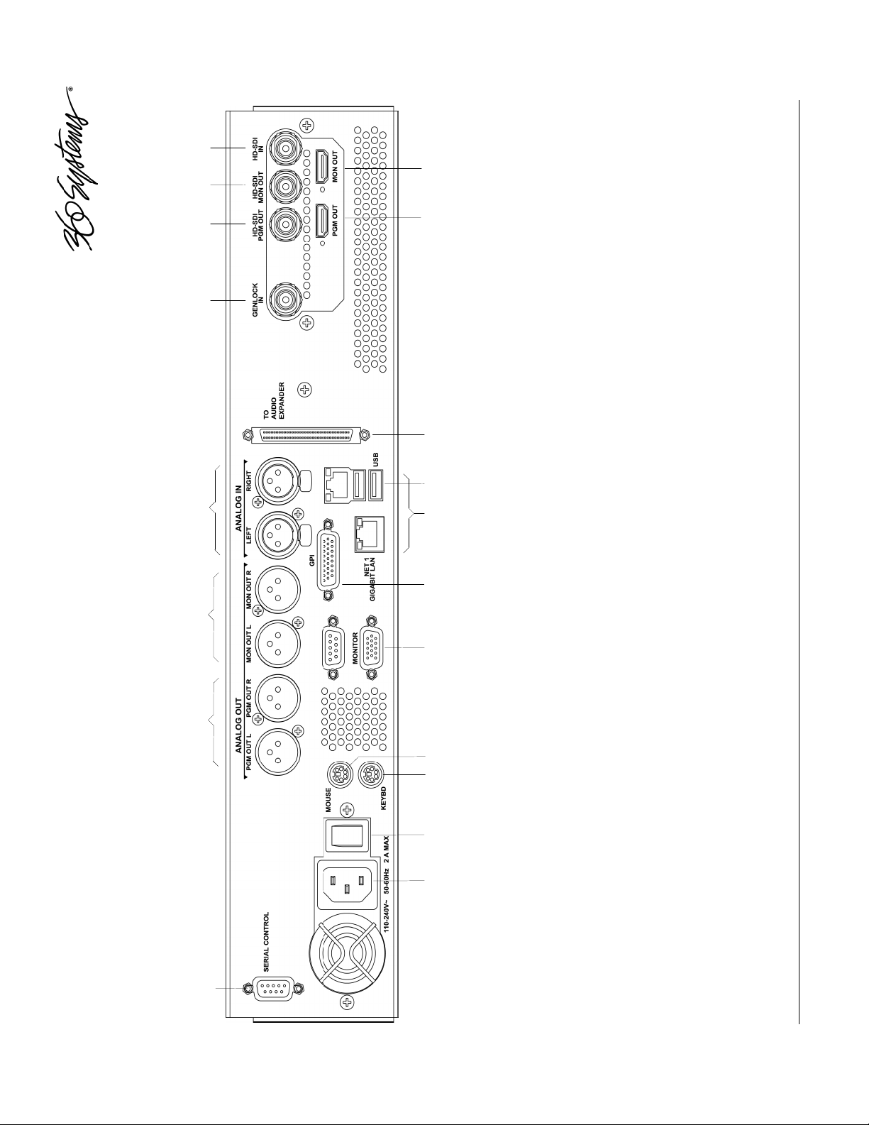
19. HDMI E-E monitor output
18. HDMI main Program output
17. Audio Expander connector
16. USB Ports (Use only for program updates)
15. Gigabit Ethernet ports (Use NET1 only.)
14. GPI port, 26-pin female
13. SVGA monitor port
12. Mouse port
11. Keyboard port
1. Serial control port (EIA-422) (Future use.)
2. (2) XLR-3 audio outputs
3. (2) XLR-3 audio monitors
4. (2) XLR-3 audio inputs
5. Genlock Input (Future Use)
6. HD-SDI main Program output
7. HD-SDI E-E monitor output
8. HD-SDI video input
9. AC Power connector
10. AC Power switch
Rear Panel Drawing
Page 15

Rear Panel Connectors
The Time Delay provides one video input with up to 16 Embedded audio channels, one
delayed video output with audio, and a second monitoring output which reflects input video and
audio (E-E).
Additionally, there are two analog audio inputs that can be used instead of embedded
audio. These correspond to audio channels 1 and 2, and appear in the embedded audio on the
video outputs and the XLR outputs. The XLR audio outputs will also carry audio channels 1 and 2
when embedded audio is selected as the input source.
The HDMI outputs carry audio channels 1 and 2 when either embedded or analog audio is
selected. Audio from other channels cannot be output by either Analog or HDMI audio.
R
EAR PANEL DESIGNATION
HD-SDI IN BNC HD-SDI Video Program Input
HD-SDI MON OUT BNC HD-SDI E-E monitor out
MON OUT HDMI Local E-E monitor
HD-SDI PGM OUT BNC Main HD-SDI Video Program Out
PGM Out HDMI Local Program output
ANALOG IN LEFT XLR Audio Channel 1 Input
ANALOG IN RIGHT XLR Audio Channel 2 Input
ANALOG PGM OUT L XLR Audio Channel 1 Main Program Out
ANALOG PGM OUT R XLR Audio Channel 2 Main Program Out
ANALOG MON OUT L XLR Audio Channel 1 E-E Out
ANALOG MON OUT R XLR Audio Channel 2 E-E Out
GPIO DB-26 Error Monitor outputs
GENLOCK BNC Future use
NET 1 RJ-45 Gigabit Ethernet (for diagnostic use)
Serial In DB-9 future use
Other Motherboard I/O various future use
C
ONNECTOR TYPE
F
UNCTION
14 2470HD Time Delay
Page 16
Operations
The Graphical User Interface
The Time Delay uses a Graphic User Interface (GUI) to control most functions. A keyboard
and mouse are included, and the user needs to supply an SVGA monitor—either CRT or flat-panel.
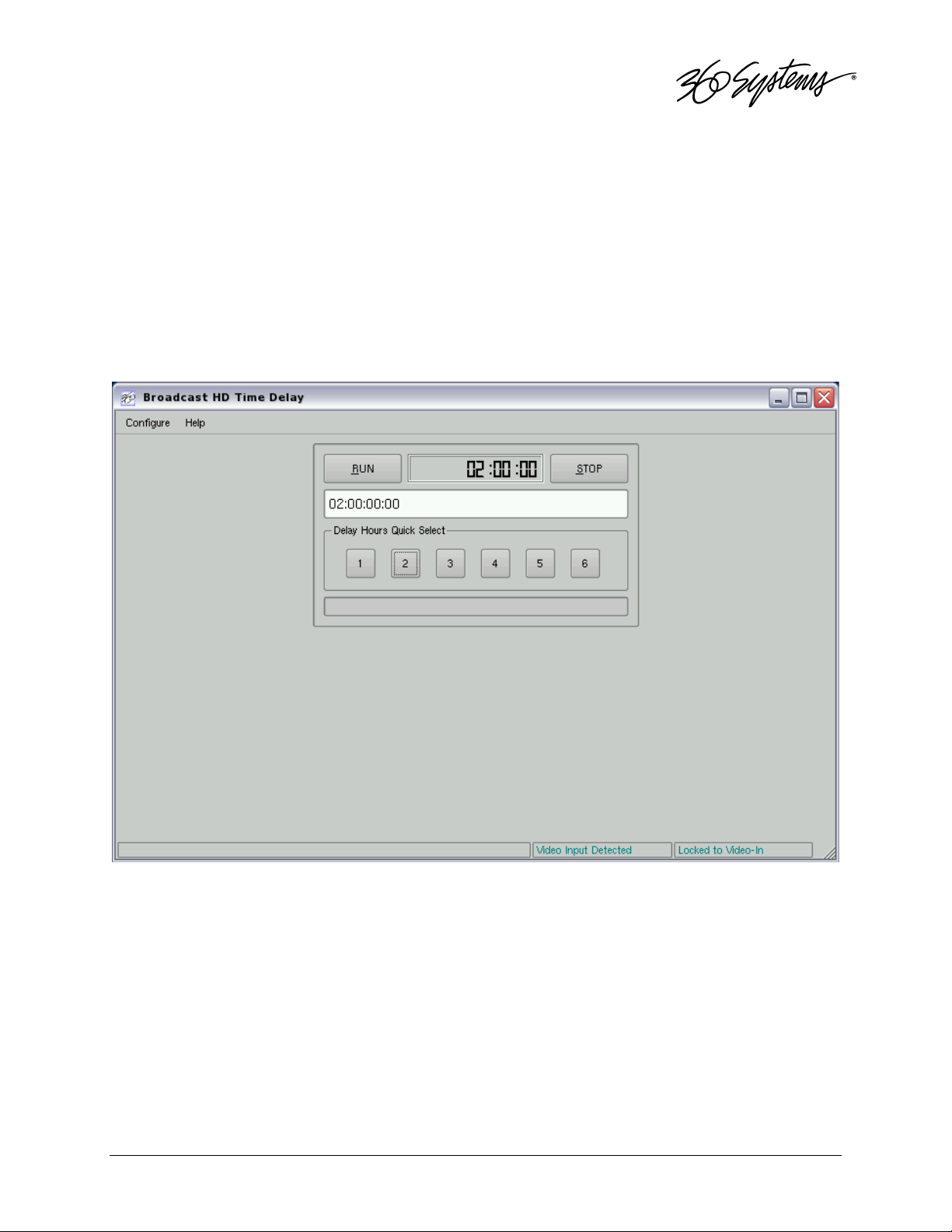
The GUI is divided into two sections: Run/Stop control, and Time Delay Set. Controls and
displays for each section are described below.
In addition, the Menu Bar provides two dialogs, accessed through Configure>Options,
and Help>About.
Graphical User Interface
Operations 15
Page 17

Run, Stop, Time to Air display
Time Delay Setting and Quick Select Presets
Run/Stop Control
Run
The RUN
RUN button initiates or restarts the time delay process. Press RUN
RUNRUN
cycle, and restart the Time-to-Air countdown. When the countdown reaches zero, it changes to
ON LINE, and the delayed video begins playing from the main Program Output.
Upon power up the Time Delay will automatically enter Run mode and start the delay
process.
RUN to begin a new delay
RUNRUN
Stop
The STOP
STOP button stops playout and clears stored program content from memory. Note that
STOPSTOP
the Time Delay value can only be changed when the machine is in the STOP
STOP mode.
STOPSTOP
Time to Air
Initially, the Time to Air display shows the selected Time Delay Setting. Once RUN
pressed and the recording process sets up and commences, Time to Air is a countdown value,
displaying the time remaining before delayed program material reaches the output. It is an
approximate display value; it is not directly locked to the video timing.
RUN is
RUNRUN
Time Delay Setting
Delay time is entered and displayed in the DELAY TIME
(Hours:Minutes:Seconds:Frames) The desired time is entered from the keyboard from left-to-right.
Delay times may also be entered as whole units of seconds, minutes, hours, by appending
a suffix, (s, m, or h) to the value entered into the text box, such as “120m” or “30s.”
Delay Hours Quick Select
Six preset buttons provide a rapid way to set a delay time to an even number of hours from
1 to 6. With the machine stopped, clicking on one of these buttons will immediately load that time
value, expressed in hours. An appropriate number of zeros will also be entered for MM:SS:FF. The
presets are not active while the machine is running.
DELAY TIME window in HH:MM:SS:FF format.
DELAY TIMEDELAY TIME
16 2470HD Time Delay
Page 18

Configure Options Dialog
Configure Options Dialog
Main Screen Title
This allows a user selected title to replace the default “Time Delay” in the title bar of the main GUI
window.
Video Mode
Four radio buttons select the Video Mode, which includes the frame rate and video format. These are:
59.94 Hz / 720p
59.94 Hz / 1080i
50 Hz / 720p
50 Hz / 1080i
This setting can only be changed when the Time Delay is stopped. When it is changed, the
unit will display a warning and then automatically perform a quick restart to initialize in the newly
selected mode.
Operations 17
Page 19

Audio Input Source
Three radio buttons select the input source for audio. These are:
SDI Embedded Audio
AES Digital Audio (when optional DXP-5 interface is connected)
Analog Audio
The Analog audio inputs are the pair of +4 dBu analog XLR inputs on the rear panel.
This setting can only be changed when the Time Delay is stopped.
Regardless of the input selected, audio will always appear in parallel, both in the
embedded audio HD-SDI stream, the analog XLR outputs and the optional DXP-5 AES/EBU
outputs. The input selection affects how many channels are available. With Analog, channels 1
and 2 are active and channels 3-16 will carry silence on embedded audio and AES/EBU outputs.
With AES/EBU selected, channels 9-16 of the embedded audio output will carry silence.
The 2470HD Time Delay supports embedded audio in groups 1-4, which includes Audio
Channels 1-16, providing 24-bit,
48 KHz, synchronous audio, as per SMPTE 299M.
VANC Line Selection
This field accepts either a comma separated list of
specific line numbers, or the limits of a range separated by a
hyphen as shown here.
• In 720p operation, up to 12 lines can be specified. Valid line numbers are in the
range of 1 to 25.
• In 1080i operation, up to 6 lines can be selected from field 1; the corresponding
lines in field 2 will automatically be recorded. Valid line numbers in 1080i are in
the range of 1 to 20.
18 2470HD Time Delay
Page 20

Output Timing
This controls the timing relationship of the output to the
reference, which is the input video. (The GENLOCK
and is reserved for future use.)
Note that these timing adjustments apply only to the Delay
output, not the Monitor output. The monitor outputs are designed
for confidence monitoring only, and are not timed.
In most applications these adjustments are not necessary. They are only used in
environments where the output must be adjusted to match other timed equipment, for example
when using a switcher or video mixer that requires precise timing alignment.
Both adjustments are made by using numeric entry from the keyboard or the Up and Down
Arrow buttons next to the parameter’s numeric display.
The Output Timing values are the only parameters that are adjustable while the Time Delay
is in RUN to allow timing while in operation. Adjustments take effect immediately without using
Apply or OK, allowing the effects to be seen easily. The picture will blank while the change takes
effect.
GENLOCK input is not active
GENLOCKGENLOCK
Vertical (Lines)
Adjusts the output line timing in relation to the reference, by an amount equal to one complete
line. The adjustment range is -4 to +30 lines.
Horizontal (nsec)
Adjusts the output line timing in relation to the reference, by an amount equal to one half pixel.
The adjustment range is ±100,000.
The Up/Down Arrow buttons increment in steps of 10 nsec.
Operations 19
Page 21

Configure Network
Network parameters are set in the Configure Network dialog. Network communication for
the Time Delay is designed primarily to support access to error logs and factory diagnostics. It can
also support automatic time updates using the NTP protocol. The system time is used only in the
diagnostic system message logs, it does not affect the operation of the Time Delay in any way.
Use only the NET1 connection on the rear panel to connect to the network. Make no
connection to NET2.
Configure Network dialog
Use the Configure Network dialog to configure network communication settings.
From the Main Menu selection bar at the top of the screen, select Setup>Options, then in
the window on the left select Network.
Each Time Delay is shipped with a unique default network Host Name and IP Address.
Qualified network engineers may change these configurations to suit your specific network
environment. Factory defaults for networking are:
• Disable Network is checked
• Use DHCP is unchecked
Disable Network Checkbox
This selection turns the network off or on. The default is Disable.
20 2470HD Time Delay
Page 22

Use DHCP Checkbox
Enabling DHCP will configure the network interface automatically.
If the DHCP box is not selected, the user may then manually enter assignments in the
following windows:
• Host Name
• IP Address
• Net Mask
• Default Router
• Name Server
Host Name may be a fully qualified domain name, such as edit1.mydomain.com. All other
manually configured addresses must be properly formatted IP addresses.
Saving Network Configuration
Click on OK or APPLY to accept new entries. To abandon unsaved changes and return to the
current setting, click the red close box at the upper right of the dialog window. Changes will
not take full effect until the Time Delay is powered off and back on.
Operations 21
Page 23

Date and Time
Date and Time are used only for display in the GUI and internal error-logging, the system time
has no effect on the operation of the video delay.
From the Main Menu selection bar at the top of the screen, select Configure>Options, then
select Date/Time in the window at left.
The date and time in the Time Delay’s system clock can be set by entering values in the Time
Set window. To enable the NTP service, check the Automatic Updates box. A valid entry for at least
one NTP server must be made in the Network setup dialog, and the network must be configured and
connected. See the next section for information on NTP.
The date and time should only be set when the Time Delay is in STOP mode.
Date and Time dialog
Network Time Protocol
Automatic Date/Time Updates
The Time Delay’s clock can be set automatically from a network time server that is referenced to
Coordinated Universal Time (UTC).
This is accomplished using the Network Time Protocol (NTP). A time server could be an in-house
computer that is equipped with a GPS receiver, or a radio receiver locked to signals from the NIST
radio station W W V . Alternatively, public time servers may be used which are accessible through an
Internet connection.
22 2470HD Time Delay
Page 24

Connecting to the Network
To obtain automatic date/time updates from the public time servers on the Internet, you will need to
provide the server with Internet access. Generally, servers would be connected on a secure highspeed local area network, with any Internet connection going through a router with an integrated
firewall. The Network Time Protocol uses TCP/IP port number 123, so be sure the firewall is
configured to allow access to this port per Figure 1.
Figure 1 - NTP Network Block Diagram
Configuring NTP
The Time Delay GUI is used to set the time zone and to enter the networking parameters.
Selecting the Time Zone
Starting at the main menu bar, Click Edit->Configure->Date-Time screen. When “Automatic
Updates” is not checked, the Region and Zone lists are enabled. Select your region and then the zone
within that region. There may be more than one way to your zone; America/New York, for example,
is the same as US/Eastern. Click the APPLY button to activate the settings.
After changing the time zone a Quick Restart must be performed before changes become
effective.
Operations 23
Page 25

Date/Time Configuration Screen
Entering Network Parameters
From the GUI’s main menu bar, Click EDIT>CONFIGURE>NETWORK. The screen below appears.
Make sure the basic network parameters have been entered.
Disable Network: uncheck
24 2470HD Time Delay
Network Configuration Screen
Page 26

Host Name: (Any name will suffice, but since this name appears on each line of the Time Delay’s
diagnostic logs, it is a good idea to keep this short.) The name should also be unique from other
devices on the network.
If “Use DHCP” if not checked, then enter a fixed IP address compatible with your local subnet.
For example,
IP Address: 192.168.1.20
Net Mask: 255.255.255.0
Default Router: 192.168.1.1
The Name Servers and NTP Servers fields provide the information needed to reach the public time
servers.
The NTP Servers field contains a list of time servers, either by numeric IP address, or by site name
(URL). Entries are separated by spaces.
The nonprofit Internet Systems Consortium, Inc. (ISC) maintains sites that automatically return lists of
public time servers to an NTP client such as the server. Hence, the NTP Servers field is initially filled
in with the URL’s for these sites (0.pool.ntp.org, for example). Of course, this list with the addresses
of specific time servers you may want to use can be overwritten. However, any attempt to clear the
NTP Servers field will reset it to the default list.
Note: When URLs (non-numeric site address such as pool.ntp.org) are used in the NTP Servers
field, the IP address of at least one DNS (Domain Name server) in the Name Servers field must be
provided. Typically, this address is supplied by the Internet Service Provider.
These name servers translate URL names into numeric IP addresses needed to access the sites in
question.
When using a GPS-based time server which is connected directly to a local area network, enter its
numeric IP address (such as 192.168.1.60) into the NTP Servers field, leaving the Name Servers field
blank.
Also, if the numeric IP addresses of the public or corporate time servers on the Internet is known,
these addresses can be entered, separated by spaces, in the NTP Servers field, leaving the Name
Servers field blank, since there would be no URLs to be resolved.
Note: Not all time servers allow unlimited public access. Refer to www.ntp.org for more
information.
Click the APPLY button to save your changes.
Operations 25
Page 27

Technical Specifications
Video
Time delay Adjustable, 6 sec to 8 hours
Time set format HH:MM:SS:FF (True number of frames per hour)
Video reference Synchronizes to video input.
Accuracy Frame accurate.
Inputs
Outputs 1 delayed output, 1 E-E monitor.
Video standards 1080i or 720p selectable
Field rates 50 Hz or 59.94 Hz selectable
Compression format JPEG2000, 100 Mb/sec
Audio
Embedded Audio 16 channels Groups 1-4 per SMPTE 299M
Analog Inputs/Outputs 2 audio channels per video channel (corresponds to Embedded
Analog audio I/O format Balanced, +4 dBu, XLR-3 connector
Audio coding 48k sample rate, 24-bit word, Linear PCM
Bit-for-Bit® capable Transparent to Dolby-E, Dolby-AC-3
Optional DXP Digital Audio
Interface
Digital Inputs/Outputs 4 stereo pairs (8 channels) per video channel. (Corresponds to
Digital audio format AES/EBU, XLR-3 connector (AES-3-2000)
Ancillary Data
Line selection – 720p Up to 12 lines in the range of 1 to 25.
Line selection – 1080i Up to 6 Field 1 lines in the range of 1 to 20.
Closed Captions Records and plays CC data on line 9 per EIA-708B
ATC time code Reproduced as recorded with delayed video.
Network Communications
Network port Gigabit Ethernet
Transfer protocol FTP
Data available Error log
Disk Storage
Drives (4) 300 GB 10,000 RPM Serial ATA in RAID-5 array
Drive access Accessible/replaceable from front panel
1 HD-SDI, 75Ω BNC connector
Each available as both HD-SDI 75Ω BNC and HDMI
Audio Group 1 channels 1 & 2)
Embedded Audio Groups 1 and 2.)
Each corresponding Field 2 line is automatically selected for a
possible total of 12 lines.
26 2470HD Time Delay
Page 28

Miscellaneous
Operating system Linux®
Front panel indicators LED: Power-on, Genlock, Fan alarm, RAID alarm, System
alarm
Miscellaneous ports Keyboard, mouse, SVGA display, Ethernet
GPI control inputs/outputs 26-pin high density D connector
Serial control input 9-pin, EIA-422, future use
Cooling Forced air
Power 100 to 240 volts universal, 50/60 Hz, 165 watts
Mechanical 3½” x 19” x 18” (89 x 483 x 457 mm) H-W-D
Mounting Rack mount (2U)
Weight 27 lb. (10.6 Kg) net
Country of origin U.S.A.
Agency approvals UL, C-UL, CE, FCC Class A
Technical Specifications 27
Page 29

Connector Pin Designations
Audio XLR-3 Connector Pinout
The Pinout for the XLR connectors is shown below.
Pin BALANCED ANALOG AES/EBU DIGITAL
1 SHIELD (frame ground) SHIELD (frame ground)
2 " + " or HOT Digital +
3 " – " or COMMON Digital -
Shell Frame ground Frame ground
Serial Control Connector Pinout
Serial Control is currently used for factory testing only.
Pin
1 GND
2 Transmit A (TX–)
3 Receive B (RX+)
4 GND
5 N/C
6 GND
7 Transmit B (TX+)
8 Receive A (RX-)
9 GND
Shell
EIA-422, DB9-F
Connector
Frame ground
BNC Connectors
The following note applies to all video and genlock connectors:
A BNC connector used as an output has a 75-ohm source impedance.
A BNC connector used as an input has a fixed 75-ohm termination.
28 2470HD Time Delay
Page 30

GPI Connector
The GPI connector is a high-density DB-26-F connector. The GPI outputs are used as System
Monitor outputs to indicate error conditions and system failures. These open-collector outputs may
be used to source current to drive an external LED or control input. They should not be connected
to any voltage greater than 12 volts. Care should be taken when interfacing to other equipment
that there is not a significant difference in potential between the system grounds or the AC
supplies.
GPI CONNECTOR INTERFACING SHOULD ONLY BE
UNDERTAKEN BY QUALIFIED ELECTRONICS TECHNICIANS.
GPI Connector Pinout
Pin Signal Pin Signal
7 N/C 20 N/C
8, 9, 10 GND 21, 22 +5V Source (200mA max)
11 GPO 2 -
12 GPO 4 -
13 GPO 6 -
GENLOCK
FAN
COMBINED
23 GPO 1 -
24 GPO 3 -
25 GPO 5 -
DRIVES
INPUT
SYSTEM
System Monitor Outputs and Error Conditions
The SYSTEM Error is activated whenever there is an over temperature condition of the chassis or
CPU, or a power supply voltage is detected to be out of tolerance (the combination of the front
panel SYSTEM and POWER indicators). The FAN Error monitors the CPU fan and the internal
Drive fan, not the chassis and power supply exhaust fans. The INPUT Error indicates loss of the
entire video signal, not a black picture condition. GENLOCK also indicates loss of input signal. The
COMBINED Output activates whenever any of the other errors are activated.
Open collector outputs can be wired together to create other combined signals (“wired-or”
connection). For example, you can create a combined error indicator that does not include the
GENLOCK error by wiring pins 12, 23, 24 and 25 together.
Six General Purpose Inputs are present on the DB-26-F connector but are not currently active.
Each is optically isolated from system circuitry, and individual floating returns are provided.
+5 volts may be sourced from pins 21 or 22, or provided by an external source. Current
limiting devices are provided in the unit.
Pin Signal Pin Signal
1 GPI 1 14 GPI 1 RTN
2 GPI 2 15 GPI 2 RTN
3 GPI 3 16 GPI 3 RTN
4 GPI 4 17 GPI 4 RTN
5 GPI 5 18 GPI 5 RTN
6 GPI 6 19 GPI 6 RTN
Connector Pin Designations
• 29
Page 31

INPUTS
GPI/O (DB25-F)
GPI 1 RTN
GPI 2
GPI 2 RTN
GPI 3
GPI 3 RTN
GPI 4
GPI 4 RTN
GPI 5
GPI 5 RTN
GPI 6
GPI 6 RTN
INTERNAL CIRCUITS
1K
1GPI 1
14
1K
2
15
1K
3
16
1K
4
17
1K
5
18
1K
6
19
OUTPUTS
GPO 1 23
+5V, 200mA MAX
SOURCE
11GPO 2
24GPO 3
12GPO 4
25GPO 5
13GPO 6
21
22
8
9SIGNAL GND
10
GPI Input/Output Connector Schematic
30 2470HD Time Delay
Page 32

Testing the GPI System Monitor Outputs
Using the “alarmtest” Utility.
In order to test the wiring in a new installation, there is a way to exercise the individual outputs
without having to create all of the indicated error conditions. The “alarmtest” program allows
temporarily reassigning one or all of the various outputs to the Loss of Input condition so that all
connected systems can be proven.
The alarmtest program is run from a terminal window in the GUI. To open a terminal window and
run the program:
1. Turn off NumLock on the keyboard.
2. Hold the Control and Shift keys, and briefly press the F12 function key.
3. In the resulting window, type
alarmtest Enter
4. Perform a Quick Restart.
The program will run, and instruct you to perform a Quick Restart to activate the new assignments.
Now, all of the GPI outputs are assigned to the Loss of Video Input warning. To activate the GPI
outputs, simply disconnect the video input. If you wish to see them deactivate, reconnect the
video input.
It is also possible to test individual outputs, so that crossed connections can be discovered, or
particular alarm conditions can be tested. To do this, perform the same procedure as above, but
add either an output number from 1 to 6, or the name of one of the warning signals, for example
alarmtest 1 Enter
or
alarmtest drives Enter
will cause the Output 1 DRIVES failure warning to activate whenever the video input is
disconnected. The signal name can be either all uppercase or all lowercase. The signal names are
DRIVES, GENLOCK, INPUT, FAN, SYSTEM and COMBINED.
You can change outputs by running the program repeatedly with different output specifications,
each time performing a Quick Restart to activate the new assignment. When the terminal window
opens, you can press the up arrow key to retrieve the previously typed command, and edit the
output number or name.
To restore the default assignments for normal operation, repeat the steps above with no individual
output specified:
alarmtest Enter
Be sure to perform the final Quick Restart.
Connector Pin Designations
• 31
Page 33

System Board Ports
Standard computer I/O ports on the Time Delay include video monitor, keyboard, mouse, and two
Gigabit Ethernet ports. Pinouts are provided to assist in wiring or trouble-shooting.
Keyboard and Mouse
Keyboard and mouse ports are provided on the rear panel. Both ports are provided with a
resettable fuse protecting the +5V supply to the peripheral. Use only the wheel mouse
supplied with the Time delay. Other mice may not work correctly.
SVGA Ports
A VESA-compliant VGA or SVGA computer monitor should be connected to the 15-pin
video port. The Time Delay is pre-configured to an SVGA screen resolution of 1024 x 768
and 64,000 colors. The refresh rate will auto-negotiate with the attached monitor to achieve
the best appearance. This resolution is best viewed on 17-inch or larger monitors. 360
Systems does not provide monitors for the Time Delay.
Use only VESA compliant monitors with a maximum refresh rate of at least 75 Hz.
SVGA Connector Pinout
Pin Signal Pin Signal
1 RED 9 +5V
2 GREEN 10 GND
3 BLUE 11 Reserved*
4 Reserved* 12 SDA
5 GND 13 HSYNC
6 RED RTN 14 VSYNC
7 GREEN RTN 15 SCL
8 BLUE RTN Shell Frame ground
* Pulled high to +5V.
Unused Ports
An unused RS-232 serial port may be present on the unit. This is not active and no
connection should be made to it. Also, the USB ports are for Software / Firmware updates
only. Do not connect a keyboard or mouse to them.
32 2470HD Time Delay
Page 34

Mechanical Drawing
Dimensional Drawing
Mechanical Drawing
• 33
Page 35

Program Updates from USB Memory
Program updates for the 2470HD Time Delay may be issued from time to time. The operating system
and application programs can be updated by the user from a USB Flash Drive distributed by 360
Systems. The current software version may be determined by looking in the GUI Help>About
dialog.
To install a program update, follow these instructions. Please read them completely before
beginning.
1. Discontinue all record, play, network transfer or system-level operations.
2. With power applied, insert a 360 Systems USB Flash Drive into one of the USB sockets.
3. Press the front panel power switch briefly to shutdown the Time Delay.
4. Wait 5 seconds, then press the front panel power switch again to boot from the USB
Flash Drive.
5. The Installer menu provides a choice to Update the Time Delay operating system, begin
a new complete install, or cancel the install.
Choose NEW to partition and reformat the drive array, and install the new operating
system.
The message, “Please wait while server is being installed” will appear with an activity
indicator. When installation is complete, the server will automatically reboot from its
hard disk array, and will display a copyright notice while starting up.
6. IMPORTANT! Remove the USB Flash Drive. Never leave it plugged into the server.
34 2470HD Time Delay
Page 36

Updating Firmware
Firmware is low-level code used by the video hardware; it is not server operating system
software. If a software update is to be performed as well, install it first unless instructions that came
with the software update specifically require loading a particular version of firmware. This procedure
must be done from the local GUI; it cannot be done at a Remote Workstation. The following
operation should only be undertaken by competent computer technician.
To update the firmware:
1. Power off the 2470HD Time Delay by selecting Start > Shutdown > Shutdown. Power
on again, using the front panel RESET
LEDs.
2. Once the server has finished initializing, close the GUI by clicking the ‘close’ button at the
upper right corner of the main window.
3. Open a terminal window by holding the Shift and Control keys and pressing the F12 key
on the keyboard. Stop the server application by typing:
killall app Enter
4. Insert the flash memory stick that was supplied with the firmware. Wait several seconds for
the system to recognize the flash drive.
RESET button, accessible through the small hole near the
RESETRESET
5. In the terminal window, type: loadflash Enter
You will see messages like the following:
Software/Firmware Updates 35
Page 37

After each bank is loaded, you should see the message “Verify complete”.
The procedure will continue, and finally end with the prompt and cursor:
If any of the banks indicate an error during the erase, verify, or programming phases,
IMMEDIATELY repeat the operation “loadflash Enter” without doing any other operation.
If the procedure still fails, perform this entire procedure again. Should you still encounter a
problem, please contact 360 Systems technical support.
36 2470HD Time Delay
Page 38

ace if
Maintenance
Fault Diagnostics
Front Panel Indicators
The five LED indicators on the front panel are used to diagnose fault conditions. The meaning of each
indicator is noted in the following table. During normal operation all five indicators will be on.
GENLOCK
POWER
FANS
DRIVES
SYSTEM
FLASHING indicates that there is no
signal, or an invalid signal, at the
INPUT
INPUT connector.
INPUTINPUT
FLASHING indicates that there is a
fault in the system power supply.
FLASHING indicates that there is a
fault of the internal chassis fan.
FLASHING indicates that there is a
fault in the system RAID array.
FLASHING indicates that the CPU fan
is running slow, or stopped; or that the
CPU temperature or voltage is not
within manufacturer’s specification.
Check the INPUT cable connections or
signal. (GENLOCK input is reserved for
future use.)
Shut down the Time Delay and contact 360
Systems Customer Support for further
hardware diagnosis.
Check the chassis fan operation. Repl
necessary. Do not run the Time Delay
without a working fan.
Check the RAID array status using
the utility under
START > RAID STATUS.
Shut down the Time Delay and contact 360
Systems Customer Support for further
hardware diagnosis.
The bottom line of the GUI will announce error conditions, in some cases giving further detail on
the nature of a fault. For example, when the System light is flashing, the GUI may indicate a
temperature error or a power supply voltage that is out of tolerance.
The GPI Outputs are programmed to indicate errors as well. These can be interfaced to an alarm
or warning light in installations where the GUI and the front panel are not visible to control room
personnel. See page 29.
Repairs should be performed only by qualified electronics
technicians.
Maintenance 37
Page 39

Gigabit Ethernet Indicators
The Gigabit Ethernet port NET1 has the following indicator LEDs:
Label Indication Meaning
ACT/LNK
(Left)
Green on The port is connected to a valid link partner
Green flashing Data activity
Off No link
10=OFF
100=YELLOW
1000=GREEN
(Right)
NET 2 is not active. Make no connection to this port.
Off 10 Mbps
Yellow flashing 100 Mbps
Green 1000 Mbps
Access to Components
Be certain to shut down the Time Delay, turn off the rear
panel power switch and disconnect the power cord before opening the
unit for service.
The following sections provide instruction on disassembly and re-assembly for maintenance.
The front panel is removed to allow access to the hard drives.
The top cover is removed to service an I/O card or power supply.
Removing the Front Panel
The front panel is easily removed for access to the four disk drives, or for removing the server from an
equipment rack. Using a coin or a flat-blade screwdriver, unscrew the two large panel fasteners on
the left and right sides of the face panel. Hold the panel in place while undoing the screws. Since the
loosened screws are captive, you may use them to pull the panel away from the chassis.
To re-install the front panel, tuck all wires into the chassis and move the face panel into position.
Screw the front panel fasteners back into the chassis. Tighten the front panel access screws with a
screwdriver.
NOTE: The Time Delay is vulnerable to accidental system reset while removing or re-installing the
front panel. It is recommended that the front panel be removed or attached only while the system is
OFF.
38 2470HD Time Delay
Page 40

Removing the Top Cover
Using a No. 2 Philips head screwdriver, unscrew the fourteen 6-32 Philips head screws attaching the
top cover to the rear panel.
General Handling Precautions
ESD Precautions
Observe electrostatic discharge (ESD) precautions to avoid damaging
static-sensitive components when handling any PC card or disk drive.
• When the case of your server is open and its internal parts are exposed, do not touch
any internal part without first grounding yourself to the chassis.
• Always wear a ground strap or work on an ESD-protective mat.
• DO NOT remove components from protective packaging until you are properly
grounded.
• Handle printed circuit boards by their edges or by the metal bracket.
• Don’t touch any pin, contact, lead or component on the printed circuit boards.
• Keep disk drives in their anti-static package until installed in the server.
Mechanical Concerns
• Be careful when installing I/O cards into your system. Excessive force can damage the
PC boards, cables, hard drives or the motherboard.
• Be sure each board is aligned with its slot in the mating connector before installing.
Use care to not flex any PC boards.
• Interface cable connectors must be mated carefully. Use care to not bend any of the
pins. The connectors provided are keyed to prevent upside-down insertion.
• Interface cables are fragile and must not be pinched. Ensure that their dress does not
restrict airflow from fans or heat sinks within the enclosure.
• Prior to installation, keep disk drives stored in a foam-lined protective carton to protect
them from physical damage.
Maintenance 39
Page 41

Installing/Removing I/O Cards
Follow the preceding instructions to remove the top cover. The I/O cards are accessible from the
top of the chassis. Generally, I/O cards can be extracted or installed with a No. 2 Philips
screwdriver. Each I/O card is held in place by several 6-32 X ¼” pan head or #1 Phillips screws on
the rear panel of the chassis.
Video I/O Card
Remove the four 6-32 x ¼” pan head Phillips screw holding the video card to the rear panel.
The video I/O card is also held by a support bracket near the front panel. Remove the 6-32 x
¼” pan head Phillips screw holding the bracket to the inside wall of the chassis.
While supporting the riser card, gently pull the video card and the riser card until the video
connectors are clear of the rear panel. Lift the video card from the chassis. Unplug all
interconnect cables from the video card. Immediately place the video card into a
conductive storage bag to protect it from electrostatic discharges.
Reverse the procedure to install a card. After all the screws are reinstalled, check that the
riser card, RAID card, and video card are all seated properly in their PCI connectors.
RAID Controller Card
Unplug the Serial-ATA cable from the RAID card.
Remove the 6-32 x ¼” pan head Phillips screw holding the RAID card to the rear panel.
Gently pull the card from its slot. Immediately place it in a conductive storage bag for
protection from electrostatic discharge that can damage it.
Reverse the procedure to install a card. Be certain to install the Serial ATA cable into the
RAID card connector.
Accessing the Main System Board
There are no user-configurable options on the main system board. If you suspect that the
system board is not operating properly, consult with 360 Systems before proceeding. DO
NOT undertake any repairs on it.
40 2470HD Time Delay
Page 42

Analog Audio Level Calibration
The input gain and output gain of the analog audio circuits are factory calibrated to a +4 dBu
standard. Each circuit includes a trim pot with a range of approximately ±2.5 dB. The following
procedure may be used to calibrate these for unity gain. Each trim pot is located above the XLR
connector with which it is associated. The procedure below is simplified to reestablish unity gain
in cases where only the analog inputs are in use.
Calibration Procedure
This procedure assumes that the technician is fully familiar with audio test procedures employing
Audio Precision® test equipment, or its equivalent.
1. Set the delay time to a minimum value, so that an input signal will appear at the PGM OUT
connections in as short a time as possible.
2. Use the audio generator to apply a 1 kHz sine wave at a level of +4 dBu to ANALOG IN LEFT
Initially, do not adjust the input level trim pot.
3. While observing the output level of MMMMON OUT
obtained. Only in the event that that level cannot be obtained, adjust the ANALOG IN LEFT
pot to obtain +4 dBu.
4. Observe the level of PGM
5. Repeat for ANALOG IN
ANALOG IN RIGHT
ANALOG INANALOG IN
PGM OUT L
OUT L and adjust its output trim pot to obtain +4 dBu.
PGMPGM
OUT L OUT L
RIGHT and MON OUT
RIGHT RIGHT
ON OUT LLLL, adjust its trim pot until a level of +4 dBu is
ON OUT ON OUT
ANALOG IN LEFT trim
ANALOG IN LEFTANALOG IN LEFT
MON OUT R
MON OUTMON OUT
R and PGM
R R
PGM OUT
PGMPGM
OUT R
R outputs.
OUT OUT
R R
PGM OUT
PGM OUTPGM OUT
ANALOG IN LEFT.
ANALOG IN LEFTANALOG IN LEFT
Maintenance 41
Page 43

Managing the RAID Disk Array
The Disk Array Configuration Utility provides tools for monitoring and managing the disk array.
Monitoring and troubleshooting programs automatically check the array, report problems and provide
access to RAID status information and service options.
A single drive fault should not cause data loss; but remember: the drive array is degraded and no
longer has storage redundancy. Hence, another disk failure may cause a complete loss of data and
system failure. After a drive failure it is strongly recommended that at the earliest time diagnostics be
performed, and the server be taken off line while the RAID array is rebuilt.
Error Notification and Repair
The Time Delay will notify users in the event of a fault by flashing the front panel DRIVES
flashing DRIVES
indicated in the GUI in the status bar, on the bottom of the screen and highlighted in yellow as shown
below. A GPIO Output is available that can activate a warning lamp or alarm upon a RAID or system
fault. Refer to page 29 for more information on GPIO interfacing. A drive fault can be trigged by a
variety of conditions. The first step in response to an error warning is to open the RAID CHECK
STATUS window from the On-Screen Start Menu. Click Start > System > RAID Status to launch
the Array Configuration Utility.
The RAID Maintenance window (Figure 5, page 47) displays the current status of the RAID controller
and all disks connected to the RAID system. On inspection, you will find the array in one of the
following states:
• OK, indicated by "OK" for Array Unit 0 and all Ports (drives);
• Initializing, indicated by "Initializing" on the Array Unit 0 status line;
• Degraded, indicated by "Degraded" on the Array Unit 0 status line;
• Verifying, indicated by "Verifying x%" on the Array Unit 0 status line;
• Rebuilding, indicated by "Rebuilding x%" on the Array Unit 0 status line.
DRIVES light can be triggered by a variety of conditions. A failure condition will also be
DRIVESDRIVES
GUI Drive Fault Indication
DRIVES light. A
DRIVESDRIVES
42 2470HD Time Delay
Page 44

“Verifying” is the process by which the array controller corrects data parity errors that may have
occurred because of power loss, incorrect shutdown or some other data error.
The term “degraded” refers to the state of the Array data, not necessarily the hardware or disk drives
themselves. It indicates that the parity information that protects the data is not up to date.
Parity errors may occur if the Time Delay loses power, or is improperly shut off. No data will be lost,
but the parity re-initialization process may take several hours. NEVER use the rear panel power
supply switch to shutdown the server. Shut down the system only by momentarily pressing the front
panel Reset button or selecting Start > Shutdown > Shutdown from the graphic user interface.
Note that in some cases the power may not automatically shut off after a Shutdown is executed.
When the front panel LED indicators start flashing in response to the Shutdown command, the file
system has been successfully closed and it is safe to force the power off by holding the Reset switch in
for four seconds.
A degraded array with a drive listed as “Not In Service” or “Inaccessible” is usually indicative of a
permanent drive error, typically a single disk or cable failure, but redundant data will allow normal
operations to continue. You may first try to rebuild the array with the existing drive still installed. If
the array continues to indicate a failed drive, replace the drive and then rebuild the array. A hard disk
array must be repaired using exactly the same drive model and capacity as other drives in the array.
Because specific drive models become unavailable as time goes on, 360 Systems recommends that
maintenance spares be purchased at the same time as the server.
Maintenance 43
Page 45

Log-In to the RAID Utilities
Figure 2: Log In to RAID Utilities
To log in to the RAID utilities, perform the following steps. The above screen will appear.
• Open the RAID utilities by selecting START>RAID STATUS
• In the Login window, select ADMINISTRATOR from the drop down menu.
• In the Password window, make no entry; leave it blank. In the event this does not work,
use the password “3ware”.
• Click the Login button to enter the 3ware Utilities.
44 2470HD Time Delay
Page 46

Determining the Condition of the RAID Array
Figure 3: Report of RAID Array Condition in Summary Screen
To replace a failed drive in the RAID control utility, perform the following steps. The above screen
should appear.
• Login as ADMINISTRATOR.
• Note the ERROR STATUS on this Summary Screen.
• If an error condition is indicated continue to next page.
Maintenance 45
Page 47

Displaying the Alarm Log of the Raid Array
Figure 4: Alarm Log Display
The RAID controller keeps track of any condition that would adversely affect its reliability. In the
event that an error should occur, the alarm log will be helpful in diagnosing the problem.
The above screen will appear.
• Select MONITOR>ALARMS from the screen.
• Make note of any error conditions reported, and what Port numbers they refer to.
Some examples of error messages are:
Drive Timeout Error – The drive failed to respond to a command from the controller within the
allotted time. This is sometimes a benign condition, but often indicates a hardware problem with the
drive.
Drive Error – The drive reported a data error. A rare isolated occurrence may be acceptable, but
probably indicates a drive failure.
Drive SMART Threshold Exceeded – The drive’s self diagnostic program is reporting an impending
drive failure. The drive should be replaced.
Remapping Bad Sector – This is a normal function of a hard drive’s self maintenance. As a drive ages
it is normal for sectors to fail, these are reassigned to a different part of the drive. Several may occur
within a very short period (seconds to a few minutes.). Multiple such errors within a few days may
indicate an impending drive failure.
Unclean Shutdown Detected – Power was lost without an orderly shutdown sequence, and the parity
information was not updated.
46 2470HD Time Delay
Page 48

Checking Status of the Drives
Figure 5: RAID Maintenance Display
To check the status of the RAID drive array, perform the following steps. The above screen should
appear.
• Select
• Note the status of each drive in the array.
MANAGEMENT>MAINTENANCE
.
Maintenance 47
Page 49

Removing a Degraded Drive from the RAID Unit
Figure 6: Removing Failed Drive from RAID Array Unit 0
The UNIT MAINTENANCE SCREEN above will appear.
• Remove the degraded drive from the menu by clicking Remove Drive.
• Select the Rescan Controller option on the above screen to have the system recognize
the drive as Available.
48 2470HD Time Delay
Page 50

Rebuilding the RAID Array
Figure 7: Selecting a Drive to Use in Rebuilding the Array
• Take the Time Delay offline and stop the delay process.
• Select Rebuild Unit. The REBUILD SCREEN above will appear.
• Select the available drive by clicking the check box.
•
Press OK. The RAID array will begin rebuilding with the new drive.
•
When complete, OK will be shown in the status for all ports on the MAINTENANCE menu.
Replacing Hard Drives
The server hard disk drives have been factory tested and configured in a RAID 5 array. Each drive
is numbered (0-3) and must be attached to the correctly numbered data cable. Drive bays are also
numbered.
Please read Removing the Front Panel on page 38 for instructions on accessing the hard drive bays.
Detailed information about how to replace hard drives is on page 51.
Maintenance 49
Page 51

RAID Controller Settings
The RAID controller is configured at the factory. The following is provided only to verify these
settings and to recreate them if necessary in the event the system is rebuilt. (The software
installation should configure these correctly, but they should be checked to verify accuracy.)
Do not use the Scheduled Events, Email Announcement or Remote Login features.
These settings are critical to proper operation of the system. The only parameter that can be
changed is “Continue on Source Error during Rebuild” which when turned on relaxes the condition
that any error found in the source material will stop the rebuild process.
It is particularly critical that the Write Cache be checked, and Auto Rebuild be disabled.
50 2470HD Time Delay
Page 52

Replacing a Hard Drive
Generally, the only time that a hard drive should be removed from the disk array is when the drive
array diagnostic software identifies a permanent fault. In this case, the front panel DRIVES
blink. Use the hard disk management tools to verify that a drive is at fault. The application
monitors many things about the array and individual drives, and will clearly indicate whether a
drive has failed.
Each hard drive bay is numbered 0 through 3, as are the drives. If for any reason one or more
drives have been removed, they must be reinstalled in a bay whose number matches the drive.
Installation in the wrong location will damage data stored on all drives.
1. Turn system power OFF with the front panel button. After it has shut down, turn off the AC
power switch and unplug the AC power cord.
2. Remove the front panel as described on page 38.
3. Disconnect the power and Serial ATA data cable from the drive, and remove it from the
drive bay.
4. Replace the drive, fasten the holding plate in place, and reattach drive cables. Note that
the data cables are numbered; re-attach then to the same drive location from which they
were removed.
5. Replace the front panel and tighten the two large screws.
DRIVES LED will
DRIVESDRIVES
6. Replace the AC power cord and turn on the rear panel AC switch.
7. Turn the system ON using the front panel button and check the RAID array status.
8. Check for correct operation of the Time Delay.
NOTE: All drives in the RAID array should be identical. Any replacement must have an actual
capacity equal to or larger than the drives that existed when the array was originally created.
Drives that are advertised as being a particular size vary in actual size. Before attempting to
rebuild an array, check that the size of the drive reported when it is installed is at least equal to or
larger than the existing drives in the array.
Maintenance 51
Page 53

Notices
Product Registration
Important — As the owner of new capital equipment, you will want to take advantage of the
product information, enhancements, upgrades, or notifications issued by 360 Systems. Send in
your Warranty Card so 360 Systems can remain in contact with you. Mail or fax it to 360 Systems
offices in the USA at the address given below.
Product Improvements and Upgrades
360 Systems reserves the right to make changes and/or improvements to its products without
incurring any obligation to incorporate such changes or improvements in units previously sold.
Certain features mentioned in this document may not be present in all models. The 2470HD Time
Delay is not offered for sale in all countries.
Repair Policy
A product being returned under warranty shall be sent to 360 Systems, freight prepaid, in the
original or equivalent packaging. Call 360 Systems for a return authorization number before
returning a product.
Use the following address for shipping and correspondence. 360 Systems’ offices are open
Monday through Friday, from 8:30 AM to 5:00 PM, Pacific Time.
360 Systems Telephone (818) 991-0360
Customer Service Dept. Fax (818) 991-1360
31355 Agoura Road E-mail info@360systems.com
Westlake Village, CA 91361 Website www.360systems.com
Trademarks
360 Systems, 360 Systems Broadcast and Bit-for-Bit are trademarks or registered trademarks of 360
Systems in the U. S. and/or foreign countries. Other trademarks referred to in this document are
the property of their respective owners.
Software
Software in this product is based on the work of, or copyright by, 360 Systems, SuSE® GmbH,
Montavista, Trolltech, and FreeType Team. Copyright 2003-2009 by 360 Systems.
Regulatory Certificates and Compliance
Safety
The Model 2470HD Time Delay was tested by Underwriters Laboratories and found to comply with
the following safety standards:
EN 60950, 3rd Edition, dated December 1, 2000, Standard for Safety of Information Technology
Equipment, Including Electrical Business Equipment.
52 2470HD Time Delay
Page 54

Radio Interference Compliance
Radio Interference (USA)
WARNING: This equipment has been tested and found to comply with the limits for Class A
digital device pursuant to Part 15 of the FCC Rules. These limits are designed to provide
reasonable protection against harmful interference when the equipment is operated in a
commercial environment. This equipment generates, uses, and can radiate radio frequency
energy and, if not installed and used in accordance with the instruction's manual, may cause
interference to radio communications. Operation of this equipment in a residential area is likely
to cause interference in which case the user will be required to correct the interference at his
own expense.
The user is cautioned that changes and modifications made to the equipment without approval
of the manufacturer could void the user's authority to operate this equipment. It is suggested that
the user use only shielded and grounded cables to ensure compliance with FCC Rules.
FCC Emission Limits
This device complies with Part 15 of the FCC Rules. Operation is subject to the following two
conditions: (1) This device may not cause harmful interference, and (2) this device must accept
any interference received, including interference that may cause undesirable operation.
Radio Interference (Canada)
English: This Class A digital apparatus meets all requirements of the Canadian InterferenceCausing Equipment Regulations. Français: Cet appariel numérique de la classe A respecte toute
les exigences du Reglement sur le matériel brouilleur du Canada.
Regulatory 53
Page 55

End User License Agreement
For 360 Systems® Time Delay Software
IMPORTANT
THIS IS A LEGAL AGREEMENT BETWEEN YOU (“YOU”) AND 360 SYSTEMS® (“COMPANY”).
COMPANY IS WILLING TO LICENSE THE IMAGE SERVER TIME DELAY SOFTWARE TO YOU
ONLY UPON THE CONDITION THAT YOU ACCEPT ALL OF THE TERMS CONTAINED IN THIS
SOFTWARE LICENSE AGREEMENT (“AGREEMENT”). PLEASE READ THE TERMS CAREFULLY
BEFORE OPENING THIS PACKAGE, OR IF DOWNLOADED, BEFORE INSTALLING THE
SOFTWARE, AS OPENING THE PACKAGE, OR IN THE CASE OF DOWNLOADED SOFTWARE,
INSTALLING IT, WILL INDICATE YOUR ASSENT TO THEM. IF YOU DO NOT AGREE TO THE
LICENSE TERMS, THEN COMPANY IS UNWILLING TO LICENSE THE SOFTWARE TO YOU, IN
WHICH EVENT YOU MAY RETURN THE UNOPENED SOFTWARE PACKAGE TO THE PLACE
FROM WHICH IT WAS ACQUIRED WITHIN 14 DAYS OF THE DATE OF PURCHASE AND
YOUR MONEY WILL BE REFUNDED. IF YOU ARE VIEWING THIS AGREEMENT
ELECTRONICALLY, SELECT THE “ACCEPT” BUTTON AT THE BOTTOM OF THIS PAGE TO
INDICATE YOUR ACCEPTANCE OF THE TERMS OF THIS AGREEMENT. IF YOU ARE NOT
WILLING TO BE BOUND BY ITS TERMS, SELECT THE “DECLINE” BUTTON AT THE BOTTOM
OF THIS PAGE AND THE REGISTRATION OR INSTALLATION PROCESS WILL NOT CONTINUE.
1. Company grants to You a non-exclusive license to use the Image Server Time Delay software program
(the “Software”) and any accompanying documentation (“Documentation”) solely for your internal
business needs pursuant the terms and conditions of this Agreement. The license to use the Software is
conditioned upon Your compliance with the terms of this Agreement. You shall be solely responsible
for installation of the Software.
Your use of the Software is limited to the licensing option set forth on your invoice. Each licensing
option is defined as follows:
Single User License. Software provided to You under this option may only be installed on any Image
Server owned or controlled by You, but in no event may it be used on more than one Image Server at the
same time.
Multiple User License. Software provided under this option may be installed on more than one Image
Server owned or controlled by You, the maximum number of which is indicated on the purchase invoice
for this Software.
2. You may not transfer the Software to another entity or person. Any such transfer terminates your license
under this Agreement. You shall not modify, translate, reverse assemble or reverse compile in whole or
in part the Software that is provided in object code. You may not rent, sell, time-share, lease, sublicense,
transfer, publish, disclose, display, or otherwise make available the object code or copies thereof to
others. You may not make copies of the object code except as provided herein. You shall not tamper
with, bypass or alter any security features of the Software or attempt to do so.
3. This license is not a sale. Title, ownership rights, and intellectual property rights in and to the Software
and Documentation shall remain with the Company. You agree to abide by the copyright laws and all
other applicable laws of the United States, your country, and international law. You acknowledge that
the Software design remains a confidential trade secret of Company. Failure to comply with the above
restrictions will result in automatic termination of this license and will make available to Company other
54 2470HD Time Delay
Page 56

legal remedies. You may not disclose any of Company’s proprietary or trade secret information relating
to the Software to any third party.
4. Company warrants that the Software will perform substantially in accordance with its Documentation.
Your exclusive remedy for breach of this limited warranty and Company’s entire liability shall be, in
Company’s discretion, either return of the price paid to Company by You for the Software, or repair or
replacement of the Software after Software and Documentation are returned to Company with an
applicable receipt. Company’s warranty is void if failure of the Software has resulted from accident,
abuse, modification or misapplication. COMPANY MAKES NO OTHER WARRANTIES, EXPRESS OR
IMPLIED, WITH RESPECT TO THE SOFTWARE AND DOCUMENTATION, AND SPECIFICALLY
DISCLAIMS THE IMPLIED WARRANTIES OF MERCHANTABILITY AND FITNESS FOR A PARTICULAR
PURPOSE. COMPANY DOES NOT WARRANT THAT THE OPERATION OF THE SOFTWARE WILL BE
UNINTERRUPTED OR ERROR FREE.
5. TO THE MAXIMUM EXTENT PERMITTED BY LAW, IN NO EVENT SHALL COMPANY BE LIABLE FOR
ANY SPECIAL, INCIDENTAL, CONSEQUENTIAL OR PUNITIVE DAMAGES WHATSOEVER,
INCLUDING ANY CLAIMS FOR LOST PROFITS, BUSINESS INTERRUPTION, LOST INFORMATION
OR OTHER DAMAGES ARISING OUT OF THE USE OR INABILITY TO USE THE SOFTWARE. IN ALL
EVENTS, COMPANY’S SOLE OBLIGATION OR LIABILITY UNDER THIS LICENSE IS THE
REPLACEMENT OR REPAIR OF THE SOFTWARE OR A REFUND OF THE PURCHASE PRICE.
6. You may terminate the license granted in Section 1 of this Agreement at any time by destroying or
erasing your copy of the Software. Company may terminate this Agreement immediately and without
notice if you fail to comply with any term or condition of this Agreement. In the event of termination of
this Agreement, all the sections of this Agreement will survive except for Section 1.
7. This Agreement shall be governed by and construed in accordance with the laws of the State of
California, U.S.A., without reference to conflicts of laws provisions or the 1980 U. N. Convention on
Contracts for the International Sale of Goods and, as to matters affecting copyrights, trademarks and
patents, by U.S. federal law. Any dispute with respect to this Agreement shall be brought and heard
either in the California state courts located in Los Angeles County, California, or the federal district court
for the Central District, Western Division, located in Los Angeles, California. In such event, the parties
to this Agreement each consent to the in personam jurisdiction and venue of such courts. The parties
agree that service of process upon them in any such action may be made if delivered in person, by
courier service, by telegram, by facsimile or by first class mail, and shall be deemed effectively given
upon receipt.
This Agreement sets forth the entire agreement between You and Company pertaining to the licensing of the
Software, and supersedes in its entirety any and all written or oral agreements previously existing between
the parties with respect to such subject matter. If any provision of this Agreement is held invalid or
unenforceable, such provision shall be revised to the extent necessary to cure the invalidity or
unenforceability, and the remainder of this Agreement shall continue in full force and effect. In the event of
any conflict between any provision of this Agreement and applicable law, the provisions of this Agreement
affected shall be modified to remove such conflict and permit compliance with such law, and as so modified
this Agreement shall continue in full force and effect. This Agreement may not be assigned without the
consent of Company.
License 55
Page 57

Limited Warranty
This product is warranted to the original purchaser against defects in material and workmanship for a
period of one year from the date of original purchase. This warranty covers parts and labor and is
effective when the product is used without alteration for the purpose intended by 360 Systems. This
warranty excludes products with modified or unauthorized software, that have been subject to misuse
or neglect, that have been modified, repaired improperly or by unauthorized personnel, damaged by
rough handling, abuse, improper operation, excessive temperature, lightning strike, static electricity,
electrical surges or other electrical system malfunctions, improper or inadequate maintenance or care
and that have been subject to use of unauthorized or non-conforming accessories or attachments.
This warranty also excludes normal wear and deterioration occasioned by the use of the product.
If part of the product is defective, the entire product must be returned along with the original purchase
receipt or other evidence of purchase and a description of the defect to 360 Systems, 31355 Agoura
Road, Westlake Village, California 91361. Upon receipt, its condition will be verified, and if the
product qualifies for warranty coverage, 360 Systems will, at its option, repair or replace the product
without charge. In the case of replacement, if the replacement for a defective product is no longer
available, 360 Systems will replace it with a similar product or, if not available, a product of equal
value.
Disclaimer and Limitation of Liability
The liability of 360 Systems under the foregoing warranty is limited solely to the repair or replacement
of defective material or workmanship and does not include any expense related to the shipment of the
product to or from 360 Systems or compensation for any inconvenience or loss of use of the product
while it is being repaired or replaced.
Except as expressly stated herein, 360 Systems makes no representations or warranties, either
express or implied, of any kind with respect to the product. EXCEPT AS EXPRESSLY STATED
HEREIN, 360 SYSTEMS EXPRESSLY DISCLAIMS ALL WARRANTIES, EXPRESS OR IMPLIED, OF
ANY KIND WITH RESPECT TO THE PRODUCT, INCLUDING WITHOUT LIMITATION
WARRANTIES OF MERCHANTABILITY AND FITNESS FOR A PARTICULAR PURPOSE.
360 SYSTEMS’ SOLE LIABILITY UNDER THIS LIMITED WARRANTY SHALL BE THE REPAIR OR
REPLACEMENT OF ANY DEFECTIVE PRODUCT OR ITS COMPONENTS DURING THE
WARRANTY PERIOD. IN NO EVENT SHALL 360 SYSTEMS, ITS DIRECTORS, OFFICERS,
EMPLOYEES OR REPRESENTATIVES BE LIABLE FOR DIRECT, CONSEQUENTIAL, PUNITIVE,
SPECIAL OR INDIRECT DAMAGES, LOSS OF PROFITS, INCONVENIENCE OR ANY OTHER
LOSSES DUE TO THE PRODUCT OR ITS OPERATION, DUE TO ITS FAILURE TO OPERATE IN
ACCORDANCE WITH ITS SPECIFICATIONS.
Some states do not allow the exclusion or limitation of incidental or consequential damages under
certain circumstances, so the above limitations and exclusions may not apply to you. This
warranty gives you specific legal rights, and you may also have other rights which vary from state
to state.
56 2470HD Time Delay
Page 58

Index
360 Systems
Customer Service ..........................................52
E-mail ...........................................................52
Fax................................................................52
Telephone.....................................................52
Website ........................................................52
Address, 360 Systems................................................52
AES/EBU ...................................................................28
Analog Audio............................................................18
Audio Input Source ...................................................18
Audio Level Calibration.............................................41
Calibration
Audio Level ..................................................41
Configure Options Dialog .........................................17
Connector Pinout
Audio XLR-3 .................................................28
GPI ...............................................................29
Serial Control................................................28
SVGA............................................................32
Connectors................................................................13
BNC..............................................................28
Customer Service ......................................................52
Delay Hours Select....................................................16
Disk Array
Repair ...........................................................42
Disk Array Management............................................42
Drawing
Mechanical ...................................................33
Rear Panel.....................................................13
Drives
LED...............................................................37
Embedded Audio
input selection ..............................................18
EULA ........................................................................54
Fans LED...................................................................37
Fault Diagnostics.......................................................37
LEDs .......................................................12, 37
Firmware Updates from USB Memory .......................35
Front Panel
Removing .....................................................38
Front Panel Features ..................................................12
Front Panel Indicators................................................37
Genlock
LED...............................................................37
Handling Precautions ................................................39
Hard Drive
Replacement .................................................51
Horizontal (nsec) adjustment .....................................19
I/O Card
RAID.............................................................40
Video............................................................40
Indicators ..................................................................12
Installation ..................................................................8
Installing Hard Disk Drives..................................49, 51
Installing/Removing
I/O Cards ......................................................40
Keyboard ..................................................................32
KVM Switch ................................................................8
LED Indicators...........................................................37
Main Screen Title ......................................................17
Maintenance .............................................................37
Mechanical Concerns................................................39
Mechanical Drawing .................................................33
Motherboard .............................................................40
Mounting ....................................................................8
Mouse.......................................................................32
Network
DHCP...........................................................21
Network Time Protocol .............................................22
Notices, General .......................................................52
NTP ..........................................................................22
Output Timing ..........................................................19
Pinout
GPIO ............................................................ 29
Power Conditioning ....................................................9
Power LED................................................................37
Power ON/OFF (Reset) Button...................................12
Program Updates from USB Memory.........................34
Quick Select Presets ..................................................16
Rack Mounting............................................................8
Radio Interference Compliance .................................53
RAID
Card .............................................................40
Controller Settings ........................................50
Repair........................................................... 42
RAID Array Management ..........................................42
Rear Panel
Drawing .......................................................13
Features ........................................................13
Indicators...................................................... 38
Recommended UPS Models ......................................10
Regulatory Compliance .............................................52
Repair .......................................................................52
Replacing a Hard Drive .............................................51
Replacing Hard Disk Drives ......................................49
Reset Button..............................................................12
RFI/EMI interference..................................................10
Run/Stop Control.......................................................16
Schematic
GPIO ............................................................ 30
Service
Access .......................................................... 38
Front Panel ................................................... 38
Top Cover .................................................... 39
Settings - RAID Controller .........................................50
Shutdown .................................................................43
Software License Agreement......................................54
Software Version .......................................................34
SVGA Connector Pinout............................................32
Index 57
Page 59

Symbols
Warning And Information ...............................4
System Board Ports....................................................32
System Cooling ...........................................................9
System LED...............................................................37
System Monitor Outputs............................................31
Testing GPI System Monitor Outputs .........................31
Time Delay Presets....................................................16
Time Delay Setting....................................................16
Time to Air................................................................16
Timing, Output .........................................................19
Top Cover
Removing .....................................................39
Trouble Shooting.......................... See Fault Diagnostics
Updating Firmware ...................................................35
UPS power conditioning .............................................9
USB
Firmware Updates ........................................35
Program Updates ..........................................34
VANC Line Selection ................................................18
Vertical (Lines) timing adjustment..............................19
Video I/O Card..........................................................40
Video Mode..............................................................17
Warranty...................................................................56
Wiring
GPIO Schematic ........................................... 30
58 2470HD Time Delay
 Loading...