


 Loading...
P.2
p.18
S.34


 P.50
P.50
E F G J 1

Precautions
Location
Using the unit in the following locations can result in a
malfunction.
•In direct sunlight
•Locations of extreme temperature or humidity
•Excessively dusty or dirty locations
•Locations of excessive vibration
Power supply 


Please connect the designated AC adaptor to an AC outlet of the correct voltage. Do not connect it to an AC outlet of voltage other than that for which your unit is intended.
Interference with other electrical devices
This product contains a microcomputer. Radios and televisions placed nearby may experience reception interference. Operate this unit at a suitable distance from radios and televisions.
Handling
To avoid breakage, do not apply excessive force to the switches or controls.
Care
If the exterior becomes dirty, wipe it with a clean, dry cloth. Do not use liquid cleaners such as benzene or thinner, or cleaning compounds or flammable polishes.
Keep this manual
After reading this manual, please keep it for later reference.
Keeping foreign matter out of your equipment
•Never set any container with liquid in it near this equipment. If liquid gets into the equipment, it could cause a breakdown, fire, or electrical shock.
•Be careful not to let metal objects get into the equipment. If something does slip into the equipment, unplug the AC adaptor from the wall outlet. Then contact your nearest Korg dealer or the store where the equipment was purchased.
THE FCC REGULATION WARNING (for U.S.A.)
This equipment has been tested and found to comply with the limits for a Class B digital device, pursuant to Part 15 of the FCC Rules. These limits are designed to provide reasonable protection against harmful interference in a residential installation. This equipment generates, uses, and can radiate radio frequency energy and, if not installed and used in accordance with the instructions, may cause harmful interference to radio communications. However, there is no guarantee that interference will not occur in a particular installation. If this equipment does cause harmful interference to radio or television reception, which can be determined by turning the equipment off and on, the user is encouraged to try to correct the interference by one or more of the following measures:
•Reorient or relocate the receiving antenna.
•Increase the separation between the equipment and receiver.
•Connect the equipment into an outlet on a circuit different from that to which the receiver is connected.
•Consult the dealer or an experienced radio/TV technician for help.
Unauthorized changes or modification to this system can void the user’s authority to operate this equipment.
CE mark for European Harmonized Standards
CE mark which is attached to our company’s products of AC mains operated apparatus until December 31, 1996 means it conforms to EMC Directive (89/336/ EEC) and CE mark Directive (93/68/EEC). And, CE mark which is attached after January 1, 1997 means it conforms to EMC Directive (89/336/EEC), CE mark Directive (93/68/EEC) and Low Voltage Directive (73/ 23/EEC).
Also, CE mark which is attached to our company’s products of Battery operated apparatus means it conforms to EMC Directive (89/336/EEC) and CE mark Directive (93/68/EEC).
Printing conventions in this manual
 marks a point of caution.
LCD screens printed in this manual are only for purposes of illustration, and may not match the actual display on your AX100G.
2

Contents |
|
1. Introduction -------------------------------- |
3 |
Main features ------------------------------------------- |
3 |
Front and rear panel ---------------------------------- |
4 |
Front panel -------------------------------------------- |
4 |
Rear panel -------------------------------------------- |
4 |
The modes of the AX100G ------------------------- |
5 |
Installing the batteries -------------------------------- |
5 |
2. Playing the AX100G --------------------- |
5 |
Example connections -------------------------------- |
5 |
Turn on the power ------------------------------------- |
5 |
Program mode ----------------------------------------- |
6 |
Input level switch setting -------------------------- |
6 |
Adjusting the volume (master volume) -------- |
6 |
Selecting a program -------------------------------- |
6 |
Checking the effects used by a program ------ |
6 |
Bypass, Mute ----------------------------------------- |
6 |
Auto tuner --------------------------------------------- |
6 |
Rhythm ------------------------------------------------ |
7 |
AUX IN ------------------------------------------------- |
7 |
Expression pedal ------------------------------------ |
7 |
Effect Select mode ------------------------------------ |
7 |
Entering Effect Select mode ---------------------- |
7 |
Exiting Effect Select mode ------------------------ |
7 |
Phrase Trainer mode --------------------------------- |
8 |
3. Editing --------------------------------------- |
9 |
Editing the effects ------------------------------------- |
9 |
Drive Amp effect Quick Edit function ----------- |
9 |
Editing the Drive Amp effect (example) -------- |
9 |
Editing other effects ------------------------------- |
10 |
Modifying the program name --------------------- |
10 |
Writing programs ------------------------------------ |
10 |
4. Appendices ------------------------------ |
11 |
Adjusting the expression pedal (Calibration) - 11 |
|
Restoring the user programs |
|
to the factory settings (Reload) ------- |
11 |
Troubleshooting -------------------------------------- |
11 |
Main specifications --------------------------------- |
12 |
Effect parameters ----------------------------------- |
12 |
DRIVE·AMP (Drive Amp effects) --------------- |
12 |
MOD (Modulation effects) ------------------------ |
13 |
PEDAL (Pedal effect) ------------------------------ |
14 |
AMB(Ambience effect) ---------------------------- |
15 |
CABI (Cabinet effect) ----------------------------- |
16 |
NR LEV |
|
(Noise Reduction, Program Level) ------------- |
16 |
Rhythm Pattern List --------------------------------- |
16 |
Preset Program Parameter List ------------------ |
17 |
1. Introduction
Thank you for purchasing the ToneWorks AX100G
Modeling Signal Processor. Introduction
In order to enjoy your AX100G to the fullest, please read this manual carefully, and use the unit correctly. Please keep this manual for future reference.
1. Main features
• Korg’s modeling technology provides detailed and powerful modeling sounds.
•63 modeling effect variations are built-in, and up to 7 effects and rhythm sounds sources can be used simultaneously.
•Forty preset programs (4 x 10 banks) and forty rewritable user programs (4 x 10 banks) are built-in.
•In Effect Select mode you can use a foot switch to change the drive amp channel or turn the Modulation effect or Ambience effect on/off.
•Virtual Feedbacker lets you sustain a note on your guitar and generate feedback with vibrato
•You can use the expression pedal to control 23 types of Pedal effect in realtime.
•When using the delay effect, you can automatically set the delay time by pressing the TAP switch to the rhythm of the song you are playing.
•The Phrase Trainer function lets you record up to 8 seconds of sound from an audio device, and play it back at a slower speed without changing the pitch.
•The Sample & Play function lets you record a phrase for a maximum of 6 seconds, and use the expression pedal for phrase play back.
•7 point LED pedal indicator
•50 different rhythm patterns and a metronome are built-in for convenient practicing.
•Built in tuner mute function for on stage silent tuning.
•An AUX IN jack is provided allowing for connection to an external audio source (CD player, cassette tape deck, etc) for play along purposes.
•Use the auto chromatic tuner to tune your instrument when the AX100G is bypassed or muted.
•The LCD (multi-display) features an intuitive visual interface.
•The LCD is backlit for easy visibility even in dark locations.
What is |
? |
 (Resonant structure and Electronic circuit Modeling System) is KORG’s proprietary sound modeling technology which precisely reproduces the complex character and nature of both acoustic and electric instruments as well as electronic circuits in real world environments.
 emulates a wide variety of sound generation characteristics including instrument bodies, speakers & cabinets, acoustic fields, microphones, vacuum tubes, transistors, etc.
3

1. Introduction
Front and rear panel
Front panel
1Type knob
This knob selects the type of Drive Amp effect that will be used.
2Value knobs
For each effect, these knobs adjust the values of the parameters assigned to the knobs. From the left, these are referred to as value knobs 1—5.
When you are not editing an effect, parameters of the drive amp effect used by the selected program are assigned to these knobs. (Refer to p.9 "Drive Amp effect Quick Edit function.")
3Select switches
Each time you press the DRIVE·AMP switch, the drive amp channels A and B will alternate, and will be in Edit mode. At this time, the LED beside the switch will change between blinking green (channel A) and blinking red (channel B).
Each time you press the MOD, PEDAL, AMB, or CABI switch, the corresponding effect will be in edit mode (on) or off. The LED beside the corresponding switch will also change between blinking (lit) and dark.
Each time you press the NR LEV switch, you will alternate between editing and on. The LED beside the switch will change between blinking and dark.
Each time you press the RHYTHM or PHRASE TRAINER switch, the corresponding function will be switched on/off. The LED beside the corresponding switch will light or go dark.
4Pedal indicator
This shows the state of the pedal effect (the depth to which it is pressed). When the tuner is operating, this shows the amount of pitch deviation. In Phrase Trainer mode, this shows the recording/playback time.
5PROG/FX SELECT switch
Each time you press this switch, you will alternate between Program mode and Effect Select mode.
6Multi-display
This displays information such as program names, parameter names and values, and editing icons.
7Number LED
This displays the program bank and program number. While the Tuner is operating, it displays the note name.
8WRITE, EXIT, TAP switches
The WRITE switch is used to write an edited program.
By pressing the EXIT switch, you can return to Program mode at any time.
When using a delay effect, you can press the TAP switch at the tempo of the song to set the delay time automatically.
9DOWN, UP switches
These switches are used to select programs, bypass or mute, or to switch the drive amp channel.
0Expression pedal
This controls the effect that is selected as the Pedal effect. After advancing the pedal all the way, you can press the pedal more firmly to switch the Pedal effect on/off.
Rear panel
1INPUT jack
If you are using batteries, this jack acts as a power switch. When a cable is connected, the power will be turned on.
 Before turning the power on or off, be sure to turn down the volume of any equipment that is connected.
2Input level switch
Set this switch according to the output of your instrument.
3AUX IN jack (stereo mini)
Connect the output (AUX OUT: analog) of your audio device to this jack.
4DC9V
The separately sold AC adapter (DC9V 

 ) can be connected here. When this is connected, the power will be turned on automatically.
5Cable hook
If the separately sold AC adapter is connected, hook the cable of the AC adapter around this hook as shown below. When removing the cable from the hook, do not apply tension.
6MASTER VOL. (Master volume)
This adjusts the volume of the OUTPUT jack.
7OUTPUT jack
This also functions as the headphone jack.
8 Cable guide
This prevents the cable that connects the guitar to the AX100G from interfering with the operation of the pedal. Pass the cable through the guide as shown in the diagram below.
 When using the cable guide, please use a cable whose diameter is 8 mm or less.
Max.
8mm
4
The modes of the AX100G
The AX100G is divided into three modes: Program mode, Effect Select mode, and Phrase Trainer mode.
Program mode
In this mode you can select programs and use the AX100G for normal performance.
Use the foot switches (UP, DOWN) to select programs. Immediately after the power is turned on, the AX100G will always be in this mode. With the factory settings, the User programs contain the same programs as the Preset programs.
Effect Select mode
In this mode you can use the foot switches UP or DOWN to switch the drive amp channel*1, Modulation effect or Ambience effect on/off.
Programs cannot be selected in this mode. Use Program mode to select programs.
*1 The AX100G provides two (A and B) Drive (distortion) Amp Effects so that you can switch between settings such as backing and solo without having to change programs.
Phrase Trainer mode
This mode allows you to record a phrase from a CD or MD connected to the AUX IN jack, and play it back as a repeated loop that you can practice along with.
Since you can slow down the playback speed without affecting the pitch, this is a convenient way to learn or practice difficult phrases.
When you enter Phrase Trainer mode, the Modulation, Pedal, and Ambience effects will be turned off automatically.
In Program mode and Effect Select mode, you can use the various knobs to edit the effect, adjust noise reduction, adjust the program level, and change the program name.
Installing the batteries
1.Lightly press on arrow A of the battery case, and slide the lid upward in the direction of the arrow to open the case.
2.Insert four AA alkaline batteries (sold separately) as shown in the diagram. Be careful to observe the correct polarity (+ and -) of the batteries.
3.Close the lid of the battery case.
If you will not be using the unit for an extended period of time, remove the batteries to prevent them from leaking.
When the multi-display blinks "BATTERY," it is time to replace the batteries. Please install new batteries as soon as possible.
2. Playing the AX100G
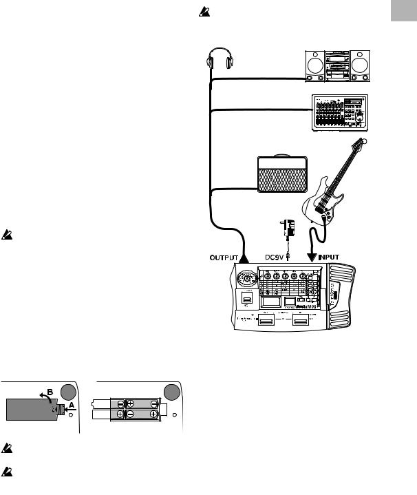
Example connections
The power must be off when making connections. Otherwise, damage to your speaker system, or other malfunctions may occur. Connecting cables are sold separately.
Headphone (*1) |
Audio system |
|
Stereo 1/4" jack – stereo RCA (phone jack)
Hard disk recorder etc.
Mono output – mono 1/4" jack / stereo output - two mono 1/4" jacks
Guitar amp / powered monitor(*1)
Mono 1/4" jack –
mono 1/4" jack
Guitar
AC adapter (*2)
to AC outlet
Mono 1/4" jack – mono 1/4" jack
*1: The OUTPUT jack is a stereo output. If you use a mono cable to connect the AX100G to a guitar amp, only the L (left) side signal will be output to the amp.
*2: If you use batteries, the AC adapter is not necessary. If you use an AC adapter, be sure to use only the specified model (DC 9V 

 ).
).
Turn on the power
The AX100G does not have a power switch.
The power will be turned on when one of the following occurs.
If you are using batteries, the power will be turned on when you connect a mono cable to the INPUT jack. To maximize the battery life, disconnect the cable from the INPUT jack when you are not using the AX100G.
 If you connect a stereo cable, the power will not be turned on.
If you are using the AC adapter (sold separately), the power will be turned on when you connect the AC adapter to a DC 9V.
Before you turn off the power of the AX100G, turn off the power of the other connected equipment.
2. Playing the AX100G
5

2. Playing the AX100G
Program mode
When you turn on the power, the AX100G will always enter Program mode, and will be set to the program setting that were last selected when the power was turned off.
Input level switch setting
Set this switch according to the output of your instrument.
H : Suitable for a pickup with a high output level, such as a humbucking pickup
L : Suitable for a pickup with a low output level, such as a single coil pickup
Adjusting the volume (master volume)
To adjust the volume, rotate the MASTER VOL. (master volume) located on the rear panel.
Selecting a program
Press the UP or DOWN switches to increment or decrement the programs in steps of one. When you do so, the multi-display will show the name of each program.
Programs are organized into groups of four, and these groups are called "banks." The current bank is shown by the 10's digit of the number LED.
Preset program
User program
The AX100G contains a total of 80 programs (sounds): 40 (4 x 10 banks) of preset programs that cannot be overwritten, and 40 (4 x 10 banks) of user programs that you are able to modify (edit). When a user program is selected, the decimal point (dot) in the lower right of the number LED will light.
Preset |
User |
program |
program |
Dot is lit
Selecting a bank
Although you can use the UP or DOWN switches to select programs across banks, you can also switch programs by bank.
1.Press and hold the PROG/FX SELECT switch for approximately one second until the number LED begins to blink.
2.Press either the UP or DOWN switch to increment or decrement the bank.
3.Press the PROG/FX SELECT switch once again to finalize the bank and make the number LED stop blinking.
Bank Hold (10’s HOLD)
By simultaneously pressing the TAP switch and EXIT switch, you can prevent programs of other banks from being selected. At this time, the decimal point (dot) at the lower right of the 10's place in the number LED will light.
Press the UP or DOWN switches to select programs within the current bank.
When you once again press the TAP switch and EXIT switch simultaneously, the Bank Hold (10’S HOLD) function will be cancelled.
Dot is lit
Checking the effects used by a program
Some programs do not use all of the effects. When you select a program, the LED beside each effect select switch will light to indicate the effects that are being used. An effect that is turned off can be edited (turned on) by pressing its select switch, and when you press another select switch or the EXIT switch, the LED will change from blinking to lit.
Bypass, Mute
By pressing the UP and DOWN switches simultaneously, you can Bypass the AX100G so that no effects will be applied. (The multi-display will indicate "BYPASS" for two second.)
Alternatively, by pressing the UP and DOWN switches simultaneously and holding them for approximately one second, you can Mute the AX100G completely so that no sound will be output. (The multi-display will indicate "MUTE" for two second.)
To defeat Bypass or Mute, press the UP or DOWN switch.
Auto tuner
When the AX100G is in bypass or mute condition, the tuner will operate automatically. If you mute the AX100G you will be able to tune your instrument without producing sound. This is used for on stage tuning.
1. Tune your guitar so that the desired note name appears in the number LED. The decimal point “.” at the lower right of the number LED will light to indicate a sharp .
2.The seven-point pedal indicator will show the difference between the pitch you play and the note name. Tune your instrument so that only the center LED is lit.
Tuning discrepancy shown by the pedal indicator and the multi-display
Pitch is |
Correct |
Pitch is |
flat |
tuning |
sharp |
Changing the calibration setting
As necessary, you can adjust the calibration (the frequency of the standard A pitch) in the range of 438—445 Hz. (440 Hz is “standard”)
When the tuner is operating, you can rotate value knob 1 to adjust the calibration. The calibration setting is shown in the multidisplay.
When the power is turned off, the calibration setting you modify will be lost, and will automatically return to 440 Hz the next time the power is turned on.
6
Loading...