


JBL E90, EC35, E100, E60, E50 User Manual
...
SPEAKER PLACEMENT
Proper placement of the speakers is an important step in obtaining the most realistic soundstage possible. These recommendations are for the optimum placement of the loudspeakers. Use these placement recommendations as a guide. Slight variations will not diminish your listening pleasure.
All of the Northridge E Series loudspeakers referred to in
this guide are video-shielded and can safely be placed near a television.
MODELS: E60, E80, E90, E100
MODELS: E30, E50
As front speakers
As surround speakers
5 – 6 ft. |
(1.5m–1.8m) |
MODEL: EC35
0 – 2 ft. 
 (0–0.6m)
The EC35 center channel loudspeaker is designed to complement all of the Northridge E Series loudspeakers. It is the ideal way to re-create the cinematic
experience in your home.
®
NORTHRIDGE™ E SERIES
E30, E50, E60, E80, E90,
E100, EC35
OWNER’S GUIDE
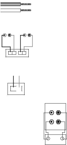
SPEAKER CONNECTIONS
MODELS: E30, E50, E60, E80, E90, E100
RIGHT |
LEFT |
– |
+ |
– |
+ |
– + |
– + |
RIGHT LEFT
Receiver’s Speaker Outputs
MODEL: EC35
CENTER
– 
 +
+
–+
CENTER
Receiver
Speaker Outputs
The hole in the center of each collar is intended for use with banana-type connectors. To comply with European CE certification, these holes are blocked with plastic inserts at the point of manufacture. To use banana-type connectors requires the removal of the inserts. Do not remove these inserts if you are using the product in an area covered by the European CE certification.
BI-WIRING
The bi-wire connection method requires one amplifier and two sets of speaker wires. By removing the shorting bars, connections may be made to the individual network sections using four conductors, one for each of the four terminals.
For single-wire connection, leave the shorting bars in place and connect only a single set of speaker wires (two conductors) to the two upper terminals.
Speakers and electronics terminals have corresponding (+) and (–) terminals. It is important to connect both speakers identically: (+) on the speaker to (+) on the amplifier and (–) on the speaker to (–) on the amplifier. Wiring “out of phase” results in thin sound, weak bass and poor imaging.
To use the binding-post speaker terminals, unscrew the colored collar until the pass-through hole in the center post is visible. Insert the bare end of the wire through this hole; then screw the collar down until the connection
is tight.
High Frequency
– |
+ |
– |
+ |
Low Frequency |
|
– |
+ |
Amplifier |
|
Bi-Wire Connections
MODELS: E30, EC35, E50
The supplied self-adhesive rubber feet may be attached to the bottom corners of your speakers to protect your furniture.
MODELS: E60, E80, E90, E100
These models feature four rubber feet that enable them to be placed on a smoothsurfaced floor, such as tile or hardwood. Four metal spikes are supplied for use when the speaker is to be placed on a carpeted surface, to decouple the speaker from the floor and prevent unwanted damping. To insert the spikes, gently lay the speaker on its side (not its front or back) on a soft, nonabrasive surface. Each spike screws into the threaded insert in the center of each rubber foot. Make sure all
four spikes are screwed in completely for stability.
NEVER drag the speaker to move it, as this will damage the spikes, the feet and/or the wood cabinet itself. Always lift the speaker and carry it to its new location.
CAUTION: Floorstanding (tower) loudspeakers have a high center of gravity and may become unstable and tip over during earthquakes, or if rocked, tipped or improperly positioned. If this is a concern, these speakers should be anchored to the wall behind them, using the same procedures and hardware customary for anchoring bookcases and wall units. The customer is responsible for proper installation and proper selection of hardware.
 Loading...