


GT5-A3001
1 CHANNEL POWER AMPLIFIER
SERVICE MANUAL
JBL Consumer Products |
|
250 Crossways Park Dr. |
|
Woodbury, New York 11797 |
Rev0 3/2008 |
Released 2007
Discontinued XXXX

GT5-A3001
- CONTENTS -
SPECIFICATIONS ………………………………………..1 |
|
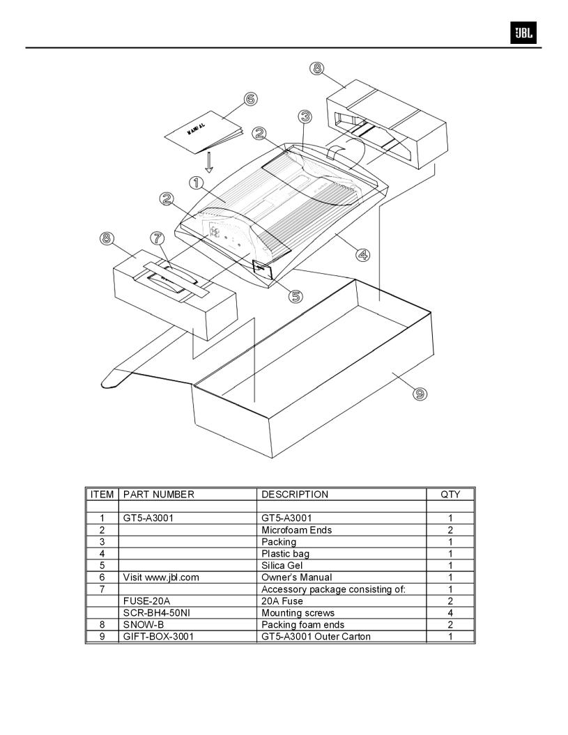
PACKING……………………………………………..…....2 |
|
CONTROL/INSTALLATION DRAWINGS………………3 |
|
CONTROL/INSTALLATION INSTRUCTIONS………....4 |
|
BASIC TROUBLESHOOTING……………………………5 |
|
EXPLODED VIEW/PARTS LIST…….….….…………....6 |
|
AMPLIFIER BLOCK DIAGRAM…………………….……7 |
|
ELECTRICAL PARTS LIST ..……….……….…….…….8 |
|
P.C.B. DRAWINGS….………………………...…….……11 |
|
IC/TRANSISTOR PINOUTS..…………………….….…..13 |
|
SCHEMATICS……………..……………….………..…...14 |
|
GT5-A3001 Specifications |
|
Output Power: |
175W RMS x1 channels @ 4 ohms; ≤1% THD + N |
(14.4V supply) |
225W RMS x 1 channels @ 2 ohms; ≤1% THD + N |
|
300W RMS x 1 channel @ 1 ohm; ≤1% THD + N |
Signal-to-noise ratio: |
95dBA (reference 1W into 4 ohms) |
|
120dBA (reference rated power into 4 ohms) |
Total Peak power: |
600W |
Frequency response: |
10Hz – 300Hz (–3dB) |
THD+N 1KHz LPF=22KHz |
≤0.05% (rated power @ 4 ohms) |
Input Impedance |
10kΩ |
Maximum input signal: |
6.0V |
Maximum sensitivity: |
200mV |
Hi-Pass, Low Pass X-over Limits |
32Hz – 320Hz ±20% 12dB/oct |
DC Offset |
<30mV |
Output regulation: |
46dB |
Idle Current @ 4 ohms |
400mA |
Max Current Draw |
≤20A |
Remote Operating Voltage |
5V |
Turn-on delay time |
3 sec |
Circuit Protection |
Temperature (85±5C), Short circuit, Operating voltage range (8-16V) |
Dimensions: |
2 1/8 x 9 1/4 x 12" (54 x 235 x 305mm) |
Fuse: |
2 x 20A |
JBL continually strives to update and improve existing products, as well as create new ones. The specifications and details in this and related JBL publications are therefore subject to change without notice.
1
GT5-A3001
2

GT5-A3001
4x |
2x |
1x |
9-1/4" 235mm
12"
305mm
2-1/8" 54mm
A B
B  C
C D
D
 A
A
3
GT5-A3001
GT5-A3001 CAR AUDIO SUBWOOFER AMPLIFIER
Installation Warnings and Tips
•Disconnect the negative (–) lead from your vehicle’s battery.
•At the installation sites, locate and make a note of all fuel lines, hydraulic brake lines, vacuum lines and electrical wiring. Use extreme caution when cutting or drilling in and around these areas.
•Choose a safe mounting location away from moisture.
•Make sure there is sufficient air circulation at the mounting location for the amplifier to cool itself.
•Mount the amplifier, using the supplied hardware.
Specifications
•175W RMS x 1 channel @ 4 ohms and ≤1% THD + N*
•225W RMS x 1 channel @ 2 ohms, 14.4V supply and ≤1% THD + N*
•300W RMS x 1 channel @ 1 ohm, 14.4V supply and ≤1% THD + N*
•THD + N: 0.05% (rated power @ 4 ohms)*
•Signal-to-noise ratio: 95dBA (reference 1W into 4 ohms)*
•Signal-to-noise ratio: 120dBA (reference rated power into 4 ohms)
•Frequency response: 10Hz – 300Hz (–3dB)*
•Total peak power: 600 watts
* CEA-2006A-compliant
0Speaker Output Connectors
•Connect the subwoofer to these terminals, observing proper polarity. Either + or – terminal may be used. Minimum total impedance is 1 ohm.
1Fuses
•Replace only with the same type and rating.
2Power Input Connectors
•+12V: Connect to the positive terminal of the vehicle’s battery. 8 AWG wire is recommended. Install an appropriate fuse holder and fuse (40A minimum) within 18 inches of the battery. Make sure the wire is not damaged or pinched during installation. Install protective grommets when routing wires through the firewall or other sheet metal.
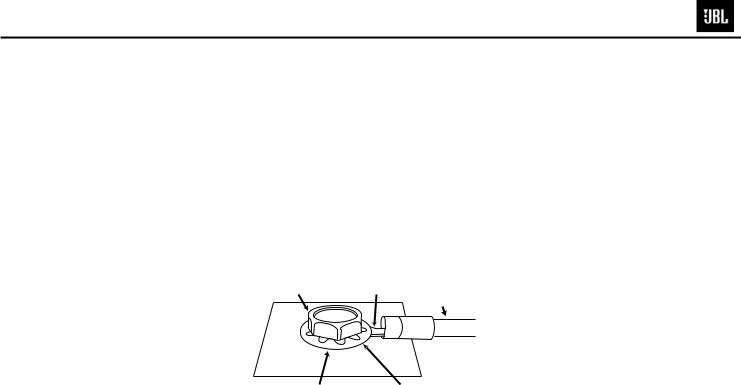
•GND: Connect to the vehicle’s chassis. Refer to the picture below.
Factory Bolt |
Ring Connector |
Gr
Note: Remove any paint S Washer below r r.
•REM: Connect to the “Remote Out” lead from the source unit or to a source of switched 12V+ (ACC).
3Aux Output Connectors (RCA)
•Nonfiltered pass-through output. Connect to the input of an additional amplifier.
4Input Connectors (RCA)
•Connect to the RCA outputs from the source unit or signal processor.
5Input-Level Control
•Used to match the input level of the amplifier to the output level of the source unit.
•See 9for the adjustment procedure.
6Protect LED
•Illuminated under any of the following fault conditions: battery over/under voltage, short circuit in speaker wires, amplifier is too hot, amplifier’s output circuit has failed (DC voltage is present in the amplifier’s output).
7Low-Pass Filter Frequency Control
•12dB/octave low-pass filter, variable from 32Hz to 320Hz.
•See Afor the adjustment procedure.
8Power On LED
•Illuminated when the amplifier is on.
9Setting Input Level
ATurn Input Level control counterclockwise to 6V (minimim).
BWith a dynamic music track playing, turn the head unit’s volume control to the 3/4 position.
CTurn Input Level control clockwise until the bass output is proportionate to the output of the high-frequency speakers, according to your preference.
DInput level is now adjusted correctly.
ASetting the Crossover
ACrossover setting for subwoofers.
Note: Acceptable frequency ranges are indicated in gray.
4
 Loading...