


 Loading...
RS/6000 7044 Model 170
Technical Overview and Introduction
February 24, 2000
Volker Haug
Jeanine Indest
Scott Vetter
International Technical Support Organization
Austin, TX
IBM
© Copyright IBM Corp. 2000
RS/6000 7044 Model 170 Technical Overview

RS/6000 7044 Model 170 Technical Overview
The IBM RS/6000 family is a scalable, software-compatible line of RISC UNIX workstations, servers, and supercomputers powered by IBMs AIX operating system. On February 7, 2000, IBM announced two exciting additions to this family, the 44P Models 170 and 270.
This paper provides a brief history, a general description, and a technical overview of the 44P Model 170 including: the 64-bit copper technology of the POWER3-II processor, the error checking and correcting (ECC) memory subsystem, the advanced packaging design, the built-in service processor, the sophisticated graphics support, and other selected features.
History
The original 43P Model 140 graphics workstation and entry-level workgroup server was introduced on October 8, 1996. This uniprocessor system offered a variety of processing speeds and features. The 43P Model 240, introduced at the same time, was the first RS/6000 workstation/workgroup server to offer expandability to 2-way symmetric multiprocessing (SMP). On October 5, 1998, IBM introduced both the 43P Model 150 and the Model 260. The Model 150 offered enhanced performance over the Model 140. The Model 260 is a 1- or 2-way SMP system utilizing the 64-bit 200 MHz POWER3 processor.
General Description
The RS/6000 44P Models 170 and 270 extend the IBM line of powerful and affordable workstation/workgroup servers with state-of-the-art, 64-bit, copper POWER3-II processors. The 44P server family, manufactured in Rochester, Minnesota, USA and Santa Palomba, Italy, offers ideal solutions for both high-performance 2D or 3D CAD/CAM users and companies that require a compact system for commercial computing solutions, such as Lotus Notes, business intelligence, Web server applications, software development, and firewall applications.
Minimum Configuration and Optional Features
The Model 170 minimum configuration includes a single POWER3-II 64-bit processor with a choice of either a 333 MHz processor with 1 MB of Level 2 (L2) cache or a 400 MHz processor with 4 MB of L2 cache. Currently, the 400 MHz processor option is the fastest POWER3-II processor available in the RS/6000 product family. Each processor is equipped with 64 KB of data and 32 KB of instruction Level 1 (L1) cache. A 10/100 Mbps Ethernet controller, one Ultra SCSI controller, one external Ultra2 SCSI controller, and the service processor are integrated on the system planar.
In addition, the Model 170 has 256 MB of ECC synchronous dynamic random access memory (SDRAM), three disk bays, three media bays, a 9.1 GB 1” Ultra SCSI disk drive, six PCI slots, a 32X CD-ROM drive, a 1.44 MB 3.5-inch diskette drive, and an operator panel. The operator panel has a 2 x 16 backlit LCD for system status and diagnostic information. Microphone and headphone jacks are built into the operator panel. The following ports are included: keyboard, mouse,
© Copyright IBM Corp. 2000 |
1 |

Ethernet (AUI and RJ45), parallel, two serial (9-pin D-shell), tablet (for use with legacy input devices), Ultra2 SCSI VHDC, and stereo/audio.
To connect external SCSI devices to the Ultra2 SCSI adapter’s VHDC, order
# 2118 (mini-68 pin VHDC to 68 pin). This 0.3 m long cable (P/N 76H0518) is not included with the minimum system configuration.
The Model 170 offers many optional features. The media bay can hold a second CD-ROM device, a 4 mm or 8 mm tape drive, or a SCSI disk drive. A media bay mounting kit is required to install a SCSI disk drive in the media bay. A variety of optional input devices are offered including: keyboard, mouse, Spaceball 3D input device, and a Magellan 3D (Spacemouse) input device.
Physical Package
The 44P Model 170 has an elegant and compact mini-tower design that was originally created for the PC IntelliStation deskside mini-tower, then revised for RS/6000 duty. The system dimensions are 19.25” H x 7.9” W x 20.25” D (490 mm x 200 mm x 515 mm). The system weight ranges from 39 lbs to 45 lbs (17.7 kg to 20.4 kg). This system is not available in a desktop or rack mounted package. Operating environment requirements are available in announcement information.
Figure 1 shows an internal view of the system with the side cover and cover support bridge removed. The CD-ROM drive, diskette drive, and one disk drive are preinstalled with each system. The remaining 5.25” media bay and two 3.5” disk bays are available for system expansion. Also, a keylock is located on the back of each system.
To open the side cover, unlock, pull the cover detent away from the rear of the unit, then slide the cover toward the front of the system unit to release the tabs.
|
Three Disk |
|
Bays |
Power |
CD-ROM |
|
|
Supply |
2nd Media |
|
Bay |
|
Diskette |
CPU |
|
Card |
|
Operator
Memory Panel
Cards
PCI
Cards
Figure 1. 7044 170 - Mechanical View
2 RS/6000 7044 Model 170 Technical Overview
System Upgrade
There are no system model upgrade conversions available for the 44P Model 170. Processor and memory expansion options are available for this system. The Model 170 is designed for customer setup of the machine and for the subsequent addition of most features (adapters and devices).
Architecture and Technical Information
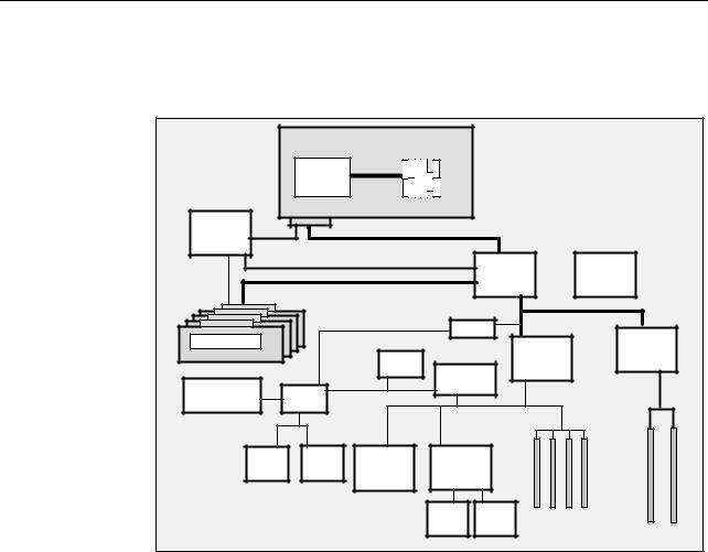
A diagram of the system architecture and logic flow for a 400 MHz system is shown in Figure 2. The 333 MHz system differences and a general discussion of this diagram is provided in the following sections.
Processor Card
4 MB L2
POWER3-II
400 MHz
32 Bytes
@ 200 MHz
Addr/Cntl |
6xx Data Bus 16 Bytes @ 100 MHz |
|
|
|
6xx Address Bus 100 MHz |
Memory |
Data |
Address |
|
|
Memory Data Bus 16 Bytes @ 100 Mhz |
System Planar
System |
Clock |
|
|
|
Arbiter |
|
|
|
|
|
Memory Modules |
|
|
|
|
|
|
|
|
256 MB -2 GB Total |
|
Boot |
|
|
PCI Bridge |
|
||
|
|
|
|
|
|
|
|
|
|
|
ROM |
ISA Bridge |
|
|
|
|
|
|
|
|
|
|
|
|
||
Integrated Service |
SP |
|
|
|
|
|
|
|
Processor |
|
|
|
|
|
|
|
|
Interface |
|
|
|
|
|
|
|
|
|
|
|
|
|
|
|
|
|
Audio |
Super |
10/100 |
Ultra-SCSI |
|
|
|
|
|
I/O |
|
|
|
|
||||
|
Ethernet |
|
|
|
|
|
|
|
|
|
|
|
|
|
|
|
|
|
|
|
External |
Internal |
S6 |
S5 |
S4 |
S3 |
|
|
|
Ultra2 |
Ultra |
||||
|
|
|
|
|
|
|
||
PCI Bridge |
2 PCI Slots
64-bit
50 MHz
3.3v
4 PCI Slots
32-bit
33 MHz
5.0v
S2 S1
Figure 2. Model 170 - System Logic Flow Diagram
Processor and Cache
The 44P Model 170 is the most affordable 64-bit system that IBM has introduced and uses the POWER3-II processor. The POWER3-II processor is designed for high-performance commercial and graphical computing applications. The processor allows for concurrent operation of up to eight instructions per cycle (three fixed-point instructions, two floating point instructions, two load/store instructions, and one branch instruction). Increasing the number of simultaneously executed instructions results in better system performance especially with applications that are optimized to take advantage of this capability.
Figure 3 is a diagram of the functional components of this processor, shown attached to the cache and bus configuration of a 400 MHz Model 170.
RS/6000 7044 Model 170 Technical Overview 3

Floating |
Floating |
Fixed |
Fixed |
Fixed |
LD/ST |
LD/ST |
Point |
Point |
Point |
Point |
Point |
Unit |
Unit |
Unit |
Unit |
Unit |
Unit |
Unit |
|
|
FPU1 |
FPU2 |
FXU1 |
FXU2 |
FXU3 |
LS1 |
LS2 |
Branch/Dispatch |
Branch history table 2048 entries |
|
|
|||
|
|
Branch target cache 256 entries |
|
|
||
|
32 KB, 128-way |
64 KB, 128-way |
|
|
||
|
Memory Mgmt Unit |
|
Memory Mgmt Unit |
|
||||
|
Instruction Cache |
|
|
Data Cache |
|
|||
|
|
IU |
|
DU |
|
|||
|
|
|
|
|
|
|
|
|
|
|
|
32 |
|
|
|
32 |
|
|
|
|
Bytes |
|
|
Bytes |
||
|
|
|
|
|
|
|
|
|
|
BIU |
|
Bus Interface Unit L2 Control, Clock |
|
||||
|
|
|
|
|
|
|
|
|
|
|
|
|
|
|
|
|
|
CPU registers: 32 x 64-bit integer (Fixed Point)
32 x 64-bit FP (Floating Point)
Register buffers for register renaming: 24 FP
16 Integer
32 Bytes |
16 Bytes |
@ 200 MHz=6.4 GB/s |
@ 100 MHz=1.6 GB/s |
|
|
Direct |
L2 Cache |
Mapped |
4 MB |
6XX Bus |
Figure 3. Model 170 - POWER3-II 400 MHz Block Diagram
POWER3 Versus POWER3-II Processors
The processor functional diagram of the POWER3 and the POWER3-II are similar; however, the use of copper in the POWER3-II represents a new generation of processing power. A single POWER3-II chip contains about 400 meters of copper wiring. Table 1 lists some of the differences between the POWER3 and the POWER3-II processors. Also, the chart indicates the direction being taken by this technology.
Table 1. Differences between POWER3 versus POWER3-II
Description |
POWER3 |
POWER3-II |
|
|
|
Chip Die Size |
270 mm2 |
163 mm2 |
Transistors |
15 million |
23 million |
|
|
|
Power Avg/Max |
39/46W@200 MHz |
28W/36W@400 MHz |
|
|
|
CMOS Technology |
6S2, 5 layers metal |
7S, 6 layers metal, copper |
|
|
interconnect |
|
|
|
Lithography |
0.25 μm |
0.22 μm |
|
|
|
4 RS/6000 7044 Model 170 Technical Overview
Loading...