


E4H SERIES
WATER PURIFICATION MACHINES
OPERATION AND
MAINTENANCE MANUAL
OPERATION AND MAINTENANCE MANUAL
FOR GE OSMONICS
E4H SERIES
WATER PURIFICATION MACHINES
TABLE OF CONTENTS
|
|
|
|
|
Page |
1.0 |
DESCRIPTION ......................................................................................................... |
1 |
|||
|
1.1 |
General Information and Principles of Operation ......................................... |
1 |
||
|
1.2 |
Machine Nomenclature.................................................................................. |
4 |
||
|
1.3 |
Machine Permeate Quality ............................................................................ |
5 |
||
|
1.4 |
Economy and Deluxe Model Options ........................................................... |
5 |
||
|
|
1.4.1 |
Economy Model ................................................................................. |
5 |
|
|
|
1.4.2 |
Deluxe Model Options ....................................................................... |
6 |
|
|
1.5 |
Specifications for E-Series Machines............................................................ |
7 |
||
|
|
1.5.1 |
Feed Water Requirements .................................................................. |
7 |
|
|
|
1.5.2 Permeate (Product Water) Flow Rate ................................................ |
7 |
||
|
|
1.5.3 |
Concentrate Flow Rate ...................................................................... |
8 |
|
|
|
1.5.4 |
Typical Pure Water ............................................................................. |
8 |
|
|
|
1.5.5 |
Final Operating Pressure .................................................................... |
8 |
|
|
|
1.5.6 |
Pump .................................................................................................. |
8 |
|
|
|
1.5.7 Reverse Osmosis Membrane Element Rejection .............................. |
8 |
||
2.0 |
INSTALLATION ....................................................................................................... |
10 |
|||
|
2.1 |
Mounting........................................................................................................ |
10 |
||
|
2.2 |
Piping |
............................................................................................................. |
10 |
|
|
|
2.2.1 |
Inlet Piping .............................................................................................. |
10 |
|
|
|
2.2.2 Valves Required for Clean-In-Place ........................................................ |
10 |
||
|
|
2.2.3 |
Concentrate Outlet Connection ............................................................... |
10 |
|
|
|
2.2.4 |
Permeate ....................................................................Outlet Connection |
10 |
|
|
2.3 |
Electrical ........................................................................................................ |
10 |
||
|
|
2.3.1 ............................................................... |
Economy Electrical System |
11 |
|
|
|
2.3.2 ................................................................... |
Deluxe Electrical System |
11 |
|
|
|
|
Page |
3.0 |
PREPARATION AND START-UP ............................................................................ |
12 |
|
|
3.1 |
Pretreatment for Water Purification............................................................... |
12 |
|
3.2 |
Start-Up.......................................................................................................... |
12 |
4.0 |
OPERATION AND MAINTENANCE ..................................................................... |
18 |
|
|
4.1 |
Daily Log Sheets............................................................................................ |
18 |
|
4.2 |
Pre-Filter Cartridge ........................................................................................ |
18 |
|
4.3 |
Flushing ......................................................................................................... |
19 |
|
4.4 |
Cleaning ......................................................................................................... |
19 |
|
4.5 |
Draining Machine for Shipment .................................................................... |
21 |
|
4.6 |
Membrane Element Installation..................................................................... |
22 |
|
4.7 |
Membrane Element Replacement.................................................................. |
23 |
5.0 |
OPTIONAL ACCESSORIES.................................................................................... |
25 |
|
|
5.1 |
Level Controls................................................................................................ |
25 |
|
5.2 |
Filters and Water Softeners............................................................................ |
25 |
|
5.3 |
Storage Tanks................................................................................................. |
25 |
6.0 |
TROUBLESHOOTING............................................................................................. |
26 |
|
7.0 |
RETURN GOODS AUTHORIZATION (RGA) PROCEDURE .............................. |
31 |
|
8.0 |
WARRANTY............................................................................................................. |
32 |
|
9.0 |
START-UP DATA SHEET......................................................................................... |
34 |
|
10. |
DAILY LOG SHEET................................................................................................. |
36 |
|
|
|
Page |
|
LIST OF FIGURES |
|
1 |
Normal Versus Cross Flow Filtration .................................... |
1 |
2 |
Membrane Element with Interconnectors.............................. |
2 |
3 |
Cross Sectional View of Membrane Element........................ |
2 |
4 |
Principles of Operation .......................................................... |
3 |
|
LIST OF TABLES |
|
1.1 |
Feed Water Requirements ...................................................... |
7 |
1.2 |
Typical Membrane Element Rejections/Passages.................. |
9 |
3.3 |
Machine Recovery ................................................................. |
16 |
4.4 |
Dry Chemical Cleaners .......................................................... |
20 |
1.0DESCRIPTION
1.1General Information and Principles of Operation
Your E-Series reverse osmosis (RO) machine is a durable piece of equipment which, with proper care, will last for many years. These instructions give operating and maintenance details vital to the sustained performance of the machine.
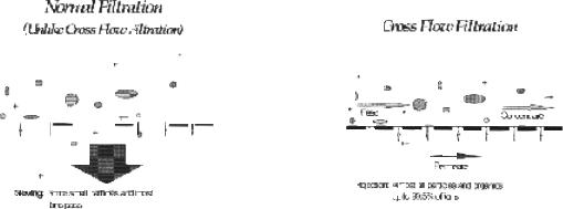
Reverse osmosis is the separation of one component of a solution from another component by means of pressures exerted on a semipermeable membrane element. Removal of ionic, organic and suspended / dissolved impurities occurs during the RO process. Unlike a filter, which separates by “normal” filtration, the General Electric (GE) Osmonics membrane element separates using a process called cross flow filtration. Feed water solution is separated into two streams, permeate and concentrate, and collected from both sides of the membrane element. A semipermeable RO membrane element, under sufficient pressure, allows passage of purified water while rejecting and concentrating dissolved and suspended solids.
Figure 1.1
Normal Versus
Cross Flow Filtration
GE Osmonics manufactures a patented spiral-wound membrane element package, with a turbulent flow design. This membrane element collects the purified water within a central tube, the permeate tube (Figure 1.2, Membrane Element with Interconnectors and Figure 1.3, Cross Sectional View of Membrane Element).
1

Figure 1.2 - Membrane Element
with Interconnectors
Figure 1.3
Cross Sectional View of
Membrane Element
2
Some operating definitions are provided to help you further understand your machine:
Permeate Rate [Product Water Rate (Qp)] is the flow rate of purified water which has passed through the membrane element and out of the membrane element housing; expressed in gal/min (gpm) or gal/hr (gph) [in metric, liter/min (Lpm) or cubic meters/hour (m3/h)]. Specified permeate rates are normally at 77ºF (25ºC).
Concentrate Rate [Waste Water Rate (Qc)] is the flow rate of water containing rejected solids to drain in gpm or gph (Lpm or m3/h).
Feed Rate (Qf) is the flow rate of incoming water in gpm or gph (Lpm or m3/h). Feedwater rate equals permeate rate plus concentrate rate.
Recovery equals permeate rate divided by feed rate and is expressed as a percentage. For example, 33% recovery means that out of a given feed rate, 33% is produced as purified water (permeate).
Concentration equals the Total Dissolved Solids (TDS) concentration of a solution expressed as milligrams per liter (mg/L) or conductivity (microSiemens/cm).
Cf |
= |
Feed Concentration |
Cp |
= |
Permeate Concentration |
Cc |
= |
Concentrate Concentration |
Cavg |
= Average Concentration in Machine |
|
Salt (Ionic) Rejection equals the percent of dissolved salt rejected by the membrane element, calculated from an average concentration over the membrane.
Salt (Ionic) Passage equals (100% - rejection) or the percent of dissolved salts passed through the membrane element.
An example of how to calculate salt rejection and recovery is given below:
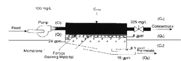
Figure 1.4
Principles of Operation
3
Given the system case in Figure 1.4 (Principles of Operation):
Average Concentration (Cavg) = |
|
(Cf) 100 mg/L + (Cc) 146.9 mg/L |
||||||||||
|
|
|
|
|
|
|
|
|
|
2 |
|
|
|
|
|
|
|
(Cavg) = 123.5 mg/L TDS |
|||||||
Rejection |
= |
|
(Cavg) 123.5 - (Cp) 6.2 x 100 = 95% |
|||||||||
|
|
|
|
(Cavg) 123.5 |
|
|
|
|
||||
Passage |
= |
|
(Cp) = 6.2 |
x 100 = 5.0% |
||||||||
|
|
|
(Cavg) |
= |
123.5 |
|
|
|
|
|
||
Recovery |
= |
|
(Qp) 2 gpm x 100 = 33% |
|||||||||
|
|
|
|
(Qf) 6 gpm |
|
|
|
|
|
|||
Flow Description - The feed water passes through a replaceable 5-micron cartridge pre-filter which removes bulk suspended solids. Filtered water then flows to the inlet control valve. This solenoid-controlled diaphragm valve is wired to the ON/OFF switch and opens when the machine is turned ON, allowing water to flow to the pump inlet. When the machine is turned off, the valve closes, preventing non-turbulent flow through the membrane elements, which would lead to shortened membrane element life.
The pump feeds water to the membrane element housings arranged in parallel and serial combinations. The direction of water flow is indicated by an arrow on each membrane element housing. Water is separated by the membrane elements within the membranes and leaves the membrane element housings in two streams: permeate and concentrate.
Permeate from each membrane element housing is collected in a common manifold. The permeate then flows through a flow meter and to the outlet point of the machine.
The concentrate leaves the last membrane element housing and flows to the flow control center (recycle/concentrate manifold). At this point, the recycle valve channels a predetermined amount of concentrate into the pump inlet. Recycle increases recovery while maintaining adequate cross flow through the membrane elements. The other two ports of the flow control center lead to the concentrate valve and final pressure gauge. The concentrate valve has three functions: It controls the amount of concentrate flowing to the drain; it controls the pressure within the machine; and it helps control the system recovery. An Autoflush solenoid is added to the flow control center with an additional tee. The concentrate then flows through a flow meter and to the outlet point of the machine.
1.2Machine Nomenclature
GE Osmonics E-Series water purification machines are numbered in such a way as to indicate the permeate flow and quality you can expect from the machine.
4
Example: |
E4H-21K/ECN, 230, 6, 50-75 |
•E4H indicates the machine series
•H indicates horizontal membrane element housing configuration
•21K indicates the rated permeate flow in thousands of gallons per day @ 77ºF (25ºC),(i.e., 21K = 21,000 gallons per day)
•ECN indicates Economy Model and DLX indicates the Deluxe Model
•230 indicates 230 VAC, three-phase voltage to starter
•6 indicates 60 Hz operation, whereas 5 indicates 50 Hz operation
•50 - 75 indicates 50% to 75% recovery
1.3Machine Permeate Quality
The permeate rejection performances are as follows:
E4H machines use high rejection Osmo 415 - HR(PA) membrane elements, providing the ultimate in high purity water.
1.4Economy and Deluxe Model Options
1.4.1Economy Model
E-Series Economy (ECN) model water purification machines have all the features necessary for safe, continuous production of high purity water. This assumes good quality feed water, adequate pretreatment and regular operator maintenance, each shift or daily, to the operation of the system.
•50% to 75% recovery
•Multi-stage centrifugal pump, SS construction (stainless steel castings with Noryl stages)
•Base model electrical package includes NEMA-1 enclosure with a 110 VAC, 60 Hz or 220 VAC, 50 Hz single-phase control circuit; applies to all ECN models
•Automatic inlet shutoff valve
•Pre-filter housing and 5-micron cartridge pre-filter
•Pre-filter, post-filter, primary and final pressure gauges
5
•Digital concentrate and permeate flow meters
•Digital conductivity monitor, panel-mounted, for permeate quality monitoring
•Autoflush System - programmable, automated high-velocity membrane element flushing for the longest membrane element life; set at the factory and adjustable in the field
•Gauges, valves and rigid piping of stainless steel or plastic
•Membrane element housings, all 304 stainless steel (SS), with Noryl end caps
•316 SS concentrate and recycle valves
•All components in contact with the purified water (permeate) are either FDA-acceptable plastic [nylon, Noryl, polypropylene, polyvinyl chloride (PVC)] or stainless steel materials.
•All high pressure fittings are 304 SS.
•Alarms included: low inlet pressure and high amp draw.
1.4.2Deluxe Model Options
The Deluxe (DLX) package contains all of the above Economy (ECN) standard features along with a PROGRAMMABLE LOGIC CONTROLLER (PLC) control system.
•Multi-stage centrifugal pump, stainless steel construction (316 stainless steel end castings and other wetted parts, Noryl internals)
•Autoflush System - programmable, automated high-velocity membrane element flushing for the longest membrane life; set at the factory and adjustable in the field
•All high-pressure fittings are 304 stainless steel.
•Special electrical upgrade package includes PROGRAMMABLE LOGIC CONTROLLER (PLC) controller with alarm delay shutdown for low inlet pressure condition to prevent pump damage should pressure fall below 15 psig (1 barg)
•Clean-In-Place (CIP) system
•Digital flow meter and conductivity controller
•Digital pH controller
6
•Alarms included: low inlet pressure, high amp draw, high / low pH
1.5Specifications for E-Series Machines
1.5.1Feed Water Requirements
|
Table 1.1 |
|
Feed Water Requirements |
|
|
Temperature |
35° - 77°F (2° - 25°C) Not to exceed |
|
85°F (29°C) unless specifically |
|
designed for higher temperatures |
|
|
Inlet Pressure |
Minimum: 30 psig (2.1 barg) |
|
Maximum: 60 psig (4.1 barg) |
|
|
Chlorine |
For Osmo HR(PA) membrane ele- |
(continuous feed) |
ments: 0 ppm |
|
|
Operating pH |
Soft water [less than 1 grain per gal- |
|
lon: 3.0 - 10.0 (gpg) or 17 mg/L hard- |
|
ness], acceptable pH: 5.5 - 6.0 |
|
|
Pre-filter |
5 micron HYTREX cartridge |
|
(part number on machine label) |
|
|
Inlet Connections |
1.5-inch FNPT* |
|
|
1.5.2Permeate (Product Water) Flow Rate
Stated on the serial number label (assumes no permeate back pressure, 2000 mg/L TDS maximum feed concentration, and rated temperature).
To estimate permeate output with back pressure, use the formula below:
(Permeate Flow on Label) x [(Operating Pressure) - (Permeate Back Pressure)] Operating Pressure
Permeate Back Pressure: |
Maximum: 80 psig (5.5 barg) |
Permeate Outlet: |
1-inch FNPT |
*FNPT: Female National Pipe Thread
7
1.5.3Concentrate Flow Rate
Factory set as stated on serial number label
Concentrate Outlet: |
1-inch FNPT |
1.5.4Typical Pure Water
Recovery: 50 - 75%
1.5.5Final Operating Pressure
Minimum: |
200 psig (13.8 barg) |
Maximum: |
235 psig (16.2 barg) |
1.5.6Pump
Multi-stage centrifugal, approximate primary operating pressure of 190 psig (13.1 barg), excluding line pressure.
1.5.7Reverse Osmosis Membrane Element Rejection
Osmo HR(PA)
Typical Ionic Rejection (TDS) |
95 - 98% |
Average Molecular Weight Cutoff* 150 MW*
*The Molecular Weight cutoff is based on the pore size of the membrane elements and the nature (size/shape) of the organic molecule.
8
 Loading...