


 Loading...
g
GEH-6632
GE Industrial Systems
EX2100™ Excitation Control
User’s Guide

g
GE Industrial Systems
Document: GEH-6632
Issue Date: 2000-09-30
EX2100™ Excitation Control
User’s Guide
© 2000 General Electric Company, USA. All rights reserved.
Printed in the United States of America.
These instructions do not purport to cover all details or variations in equipment, nor to provide for every possible contingency to be met during installation, operation, and maintenance. If further information is desired or if particular problems arise that are not covered sufficiently for the purchaser’s purpose, the matter should be referred to GE Industrial Systems, Salem, Virginia, USA.
This document contains proprietary information of General Electric Company, USA and is furnished to its customer solely to assist that customer in the installation, testing, operation, and/or maintenance of the equipment described. This document shall not be reproduced in whole or in part nor shall its contents be disclosed to any third party without the written approval of GE Industrial Systems.
Document Identification: GEH-6632
EX2100 is a trademark of General Electric Company, USA.
Cimplicity® is a registered trademark of GE Fanuc Automation North America, Inc. Ethernet™ is a trademark of Xerox Corporation.
Mate-N-Lok® is a registered trademark of Amp Incorporated. Windows NT® is a registered trademark of Microsoft Corporation.
Safety Symbol Legend
Indicates a procedure, condition, or statement that, if not strictly observed, could result in personal injury or death.
Indicates a procedure, condition, or statement that, if not strictly observed, could result in damage to or destruction of equipment.
Note Indicates an essential or important procedure, condition, or statement.
EX2100 User's Guide GEH-6632 |
Safety Symbol Legend • a |

This equipment contains a potential hazard of electric shock or burn. Only personnel who are adequately trained and thoroughly familiar with the equipment and the instructions should install, operate, or maintain this equipment.
Isolation of test equipment from the equipment under test presents potential electrical hazards. If the test equipment cannot be grounded to the equipment under test, the test equipment’s case must be shielded to prevent contact by personnel.
To minimize hazard of electrical shock or burn, approved grounding practices and procedures must be strictly followed.
To prevent personal injury or equipment damage caused by equipment malfunction, only adequately trained personnel should modify any programmable machine.
b • Safety Symbol Legend |
GEH-6632 EX2100 User’s Guide |

g |
To: |
|
GE Industrial Systems |
||
Documentation Design, Rm. 291 |
||
Reader Comments |
1501 Roanoke Blvd. |
|
|
|
Salem, VA 24153-6492 USA |
General Electric Company |
Fax: 1-540-387-8651 |
|
|
|
(GE Internal DC 8-278-8651) |
We welcome comments and suggestions to make this publication more useful.
Your Name |
Today’s Date |
If needed, how can we contact you? |
|
|
|
Fax No. |
|
Your Company’s Name and Address |
Job Site |
||
|
|||
|
|
Phone No. |
|
|
GE Requisition No. |
||
|
|||
|
|
||
Your Job Function / How You Use This Publication |
Publication No. |
Address |
|
|
|
||
|
|
|
|
|
Publication Issue/Revision Date |
|
|
|
|
|
General Rating |
Excellent |
Good |
Fair |
Poor |
Additional Comments |
|
|||||
Contents |
¡ |
¡ |
¡ |
¡ |
_____________________________________________________________ |
Organization |
¡ |
¡ |
¡ |
¡ |
_____________________________________________________________ |
Technical Accuracy |
¡ |
¡ |
¡ |
¡ |
_____________________________________________________________ |
Clarity |
¡ |
¡ |
¡ |
¡ |
_____________________________________________________________ |
Completeness |
¡ |
¡ |
¡ |
¡ |
_____________________________________________________________ |
Drawings / Figures |
¡ |
¡ |
¡ |
¡ |
_____________________________________________________________ |
Tables |
¡ |
¡ |
¡ |
¡ |
_____________________________________________________________ |
Referencing |
¡ |
¡ |
¡ |
¡ |
_____________________________________________________________ |
Readability |
¡ |
¡ |
¡ |
¡ |
_____________________________________________________________ |
Specific Suggestions (Corrections, information that could be expanded on, and such.)
Page No. Comments
______ __________________________________________________________________________________
______ __________________________________________________________________________________
______ __________________________________________________________________________________
______ __________________________________________________________________________________
______ __________________________________________________________________________________
______ __________________________________________________________________________________
Other Comments (What you like, what could be added, how to improve, and such.) ________________________________________________
___________________________________________________________________________________________
___________________________________________________________________________________________
___________________________________________________________________________________________
___________________________________________________________________________________________
___________________________________________________________________________________________
___________________________________________________________________________________________
Overall grade (Compared to publications from other manufacturers of similar products, how do you rate this publication?)
¡ Superior |
¡ Comparable |
¡ Inferior |
¡ Do not know |
Comment ____________________________________________ |
Detach and fax or mail to the address noted above.
......................................................................... |
Fold here and close with staple or tape .......................................................................................... |
____________________________ |
Place |
____________________________ |
stamp |
here. |
|
____________________________ |
|
GE Industrial Systems
Documentation Design, Rm. 291
1501 Roanoke Blvd.
Salem, VA 24153-6492 USA
...........................................................................................Fold here first.........................................................................................................
Contents
Chapter 1 Equipment Overview |
1-1 |
Introduction............................................................................................................................ |
1-1 |
System Overview ................................................................................................................... |
1-2 |
Hardware Overview ............................................................................................................... |
1-5 |
Software Overview................................................................................................................. |
1-6 |
Technical Characteristics ....................................................................................................... |
1-6 |
How to Get Help .................................................................................................................... |
1-8 |
Related Documents ................................................................................................................ |
1-8 |
Document Distribution............................................................................................. |
1-8 |
Chapter 2 Functional Description |
2-1 |
Introduction............................................................................................................................ |
2-1 |
Exciter Hardware ................................................................................................................... |
2-2 |
Exciter Configurations ........................................................................................................... |
2-3 |
Power Conversion Cabinet..................................................................................................... |
2-5 |
Manual Ac Disconnect (Optional) ........................................................................... |
2-5 |
Power Conversion Module (PCM)............................................................................. |
2-5 |
Gate Pulse Amplifiers (EGPA Board) ..................................................................... |
2-6 |
Main Dc Contactors. 41A or 41A/41B (Optional)................................................... |
2-7 |
Free Wheeling Diode De-excitation ........................................................................ |
2-7 |
Auxiliary Cabinet ................................................................................................................... |
2-8 |
Ac Line-to-Line Filters ............................................................................................ |
2-8 |
De-excitation Module (EDEX) ................................................................................ |
2-8 |
Shaft Voltage Suppressor......................................................................................... |
2-9 |
Field Flashing Module ............................................................................................. |
2-9 |
Field Ground Detector (EXAM and EGDM)........................................................... |
2-9 |
High Voltage Interface – HVI.................................................................................. |
2-9 |
Control Cabinet .................................................................................................................... |
2-10 |
Diagnostic Interface (Keypad)............................................................................... |
2-10 |
Control Module...................................................................................................... |
2-11 |
Simplex Control System ........................................................................................ |
2-12 |
Redundant Control System .................................................................................... |
2-13 |
Control Power Supplies ......................................................................................... |
2-14 |
Exciter Software................................................................................................................... |
2-17 |
Auto Reference – AUTO REF............................................................................... |
2-20 |
AVR Setpoint – EXASP ........................................................................................ |
2-20 |
Automatic Voltage Regulator – AVR.................................................................... |
2-20 |
Manual Reference – MANUAL REF .................................................................... |
2-21 |
Field Voltage and Current Regulators - FVR & FCR............................................ |
2-21 |
Under Excitation Limiter – UEL ........................................................................... |
2-22 |
Power System Stabilizer – PSS.............................................................................. |
2-22 |
Operator Interface ................................................................................................................ |
2-23 |
Turbine Control HMI............................................................................................. |
2-23 |
Control System Toolbox (toolbox)........................................................................ |
2-23 |
EX2100 User’s Guide GEH-6632 |
Contents • i |
Chapter 3 Printed Wiring Boards Overview |
3-1 |
Introduction............................................................................................................................ |
3-1 |
Control Boards ....................................................................................................................... |
3-2 |
Exciter Backplane (EBKP) ...................................................................................... |
3-2 |
Digital Signal Processor Board (DSPX) .................................................................. |
3-2 |
ACLA Board............................................................................................................ |
3-4 |
EISB Board.............................................................................................................. |
3-4 |
EMIO Board ............................................................................................................ |
3-4 |
ESEL Board ............................................................................................................. |
3-5 |
I/O Terminal Boards .............................................................................................................. |
3-5 |
EPCT Board............................................................................................................. |
3-5 |
ECTB Board ............................................................................................................ |
3-6 |
EXTB Board ............................................................................................................ |
3-6 |
EDCF Board ............................................................................................................ |
3-6 |
EACF Board ............................................................................................................ |
3-7 |
Bridge and Protection Boards and Modules........................................................................... |
3-7 |
EGPA Board ............................................................................................................ |
3-7 |
EXCS Board ............................................................................................................ |
3-7 |
EDEX Board............................................................................................................ |
3-8 |
EGDM Module ........................................................................................................ |
3-8 |
EXAM Module ........................................................................................................ |
3-9 |
Power Supply Boards............................................................................................................. |
3-9 |
EPDM Module......................................................................................................... |
3-9 |
EPBP Backplane...................................................................................................... |
3-9 |
EPSM Module ....................................................................................................... |
3-11 |
DACA – Ac to Dc Converter................................................................................. |
3-11 |
Related Board Publications .................................................................................................. |
3-11 |
Chapter 4 Terminal Board I/O and Equipment Connections |
4-1 |
Introduction............................................................................................................................ |
4-1 |
Power Connections and Analog I/O....................................................................................... |
4-2 |
Power Potential Transformer Inputs ........................................................................ |
4-3 |
Potential and Current Transformer Inputs................................................................ |
4-3 |
Analog Input ............................................................................................................ |
4-3 |
Customer Contact I/O ............................................................................................................ |
4-4 |
Power Supply Inputs .............................................................................................................. |
4-6 |
Line Filter Connections.......................................................................................................... |
4-7 |
Exciter Internal I/O ................................................................................................................ |
4-8 |
Exciter AC Feedback ............................................................................................... |
4-8 |
Exciter DC Feedback ............................................................................................... |
4-8 |
De-Excitation ....................................................................................................................... |
4-11 |
Crowbar................................................................................................................................ |
4-14 |
Field Ground Detector.......................................................................................................... |
4-14 |
Field Flashing....................................................................................................................... |
4-16 |
Dc Field Flashing Settings ..................................................................................... |
4-16 |
Flashing Control Sequence .................................................................................... |
4-16 |
Shaft Voltage Suppressor..................................................................................................... |
4-18 |
Data Highway Connections.................................................................................................. |
4-19 |
Control System Toolbox Connection................................................................................... |
4-20 |
Chapter 5 Diagnostic Interface-Keypad |
5-1 |
Introduction............................................................................................................................ |
5-1 |
Using the Pushbuttons............................................................................................................ |
5-2 |
Reading the Display ............................................................................................................... |
5-5 |
ii • Contents |
GEH-6632 EX2100 User’s Guide |
Changing Display Units........................................................................................... |
5-7 |
Adjusting Display Contrast...................................................................................... |
5-7 |
Status Screen .......................................................................................................................... |
5-8 |
Reading the Meters .................................................................................................. |
5-8 |
Alternate Status Screen (Display I/O) .................................................................................... |
5-8 |
Using the Menus .................................................................................................................... |
5-9 |
Viewing and Resetting Faults ................................................................................................ |
5-9 |
Editing Parameters ............................................................................................................... |
5-10 |
Parameter Backup .................................................................................................. |
5-11 |
Firmware and Hardware Information................................................................................... |
5-13 |
Protecting the Keypad .......................................................................................................... |
5-14 |
Modifying the Protections...................................................................................... |
5-14 |
Appendix A Warranty and Renewal Parts |
A-1 |
Introduction........................................................................................................................... |
A-1 |
Identifying the Part................................................................................................................ |
A-2 |
Renewal Parts List .................................................................................................. |
A-2 |
Part Number Structure ............................................................................................ |
A-2 |
Warranty Terms .................................................................................................................... |
A-4 |
How to Order Parts ............................................................................................................... |
A-5 |
Data Nameplate....................................................................................................... |
A-5 |
ML Number ............................................................................................................ |
A-5 |
Appendix B Ratings and Specifications |
B-1 |
Glossary of Terms |
|
Index |
|
EX2100 User’s Guide GEH-6632 |
Contents • iii |

Notes
iv • Contents |
GEH-6632 EX2100 User’s Guide |

Chapter 1 Equipment Overview
Introduction
The EX2100ä Excitation Control (EX2100 or exciter) produces the field excitation current to control generator ac terminal voltage and/or the reactive volt-amperes. It is a full static excitation system designed for generators on both new and retrofit steam, gas, and hydro turbines.
This chapter introduces the exciter and defines the document contents. Its purpose is to present a general product overview as follows:
Section/Topic |
Page |
System Overview..................................................................................................... |
1-2 |
Hardware Overview................................................................................................. |
1-5 |
Software Overview .................................................................................................. |
1-6 |
Technical Characteristics ......................................................................................... |
1-6 |
How to Get Help ...................................................................................................... |
1-8 |
Related Documents .................................................................................................. |
1-8 |
Document Distribution ..................................................................................... |
1-8 |
Chapter 2 |
Functional Description |
Chapter 3 |
Printed Wiring Boards Overview |
Chapter 4 |
Terminal Boards I/O and Equipment Connections |
Chapter 5 |
Diagnostic Interface (Keypad) |
Appendix A |
Warranty and Renewal Parts |
Appendix B |
Ratings and Specifications |
Glossary |
|
EX2100 User’s Guide GEH-6632 |
Chapter 1 Equipment Overview • 1-1 |

System Overview
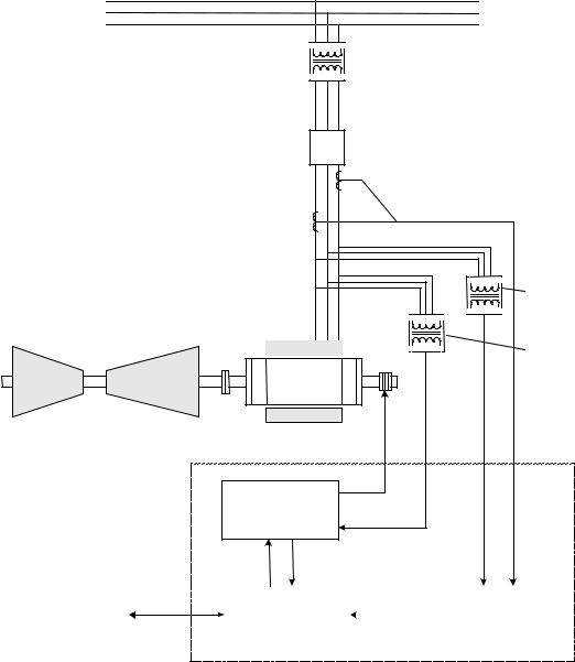
The exciter is a flexible modular system that can be assembled to provide a range of available output currents and several levels of system redundancy. These options include power from a potential, compound, or auxiliary source. Single or multiple bridges, warm backup bridges, and simplex or redundant controls are available. An overview of the turbine generator excitation system is shown in Figure 1-1.
Power for the exciter is drawn from a power potential transformer connected to the generator terminals, or from an excitation transformer connected to an auxiliary bus. Generator line current and stator output voltage are the primary feedbacks to the exciter, and dc voltage and current is the controlled output to the exciter field.
The architecture supports Ethernet LAN (Unit Data Highway) communication with other GE equipment including the GE Control System Toolbox (toolbox) for configuration, the turbine control, the LCI Static Starter, and the HMI (operator interface).
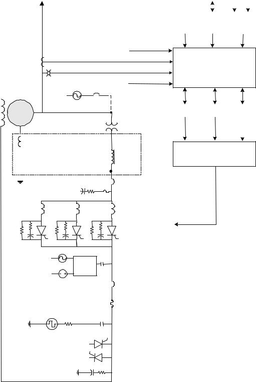
Figure 1-2 is a simplified one line diagram of the exciter showing the power source, generator current and voltage measurements, control module, power conversion module (PCM), and protection circuits. In the potential source system, the secondary of the PPT is connected to the input of a 3-phase full-wave inverting thyristor bridge. The inverting bridge provides both positive and negative forcing voltage for optimum performance. Negative forcing provides fast response for load rejection and de-excitation.
Either simplex or redundant Excitation control results from phase controlling the output of the SCR bridge control is available. circuit. The SCR firing signals are generated by digital regulators in the controller.
In the redundant control option (Figure 1-2), either M1 or M2 can be the active master control, while C monitors both to determine which should be the active and which the standby controller. Dual independent firing circuits and automatic tracking is used to ensure a smooth transfer to the standby controller.
1-2 • Chapter 1 Equipment Overview |
GEH-6632 EX2100 User’s Guide |
Transmission Line
Step-up Transformer
Air Circuit Breaker (52G)
Current Transformers (CTs)
|
|
|
Potential |
|
|
|
Transformers |
|
|
|
(PTs) |
|
|
|
Exciter Power |
|
|
|
Potential |
Turbine |
Generator |
Transformer (PPT) |
|
|
|||
|
|
Controlled |
|
|
|
dc to Field |
|
EX2100 |
Power Conversion |
|
|
Module (Bridge) |
Ac Source |
|
|
Exciter |
|
|
|
Data Highway to Turbine |
Control, |
|
|
Sequencing, |
|
Instrumentation |
|
|
|||
Control, HMI, & DCS |
Protection |
|
|
|
|
|
|
Figure 1-1 Overview of Generator and Exciter System
EX2100 User’s Guide GEH-6632 |
Chapter 1 Equipment Overview • 1-3 |
AC
Load
|
CT |
|
|
PT |
|
|
AC AC CB |
|
Generator |
Aux |
|
Source |
||
|
|
PCT (3) |
Compound |
|
|
Source only |
|
|
|
|
|
|
Line Filter
AC
DC Flashing
Control
Active Field
Ground Detector
Deexcitation
Crowbar
Shaft Voltage Suppression
Customer I/O
Current
Voltage
Bridge I/O
PPT
Linear
Reactors
(3)
AC CB or
Disconnect
Power Conversion Modules (Bridge)
DC CB or
Contactor
Shunt
Figure 1-2. Exciter One Line Diagram
|
|
|
|
AC |
DC |
|
||
|
|
|
|
|
||||
|
|
|
|
|
|
|
|
|
Diagnostic |
|
Unit |
|
|
Control |
|||
Interface |
|
Data |
|
|
|
Power |
||
(Keypad) |
|
Highway |
|
|
Supplies |
|||
I/O
Control |
|
Control |
|
Control |
|
M1 |
|
M2 |
|
C |
|
|
|
|
|
|
|
|
|
|
|
|
|
Gating Selector
PT: Potential Transformer
CT: Current Transformer
CB: Circuit Breaker
I/O: Input/Output
PCT: Power Current Transformer
PPT: Power Potential Transformer
1-4 • Chapter 1 Equipment Overview |
GEH-6632 EX2100 User’s Guide |
Hardware Overview
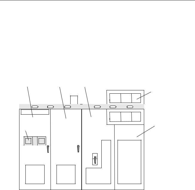
The EX2100 hardware is contained in three cabinets as follows:
•control cabinet for the control, communication, and I/O boards
•auxiliary cabinet for field flashing and protection circuits such as de-excitation and shaft voltage suppression
•power conversion cabinet for the power SCR cells, cooling fans, dc contactors, and ac disconnect
The exciter's power converter consists of bridge rectifiers, resistor/capacitor filter configurations, and control circuitry. An outside view of the cabinets is shown in Figure 1-3. The components and bridge size vary for different excitation systems and for the power output required.
Control |
Auxiliary |
Contactors & |
Cabinet |
Cabinet |
Disconnects |
|
|
Fan |
|
|
Drawers |
|
|
Power |
|
|
Conversion |
Keypads |
|
Cabinet |
|
|
Figure 1-3. Exciter Cabinets
EX2100 User’s Guide GEH-6632 |
Chapter 1 Equipment Overview • 1-5 |

Software Overview
Microprocessor-based controllers (ACLA and DSPX) execute the exciter control code. The software consists of modules (blocks) combined to create the required system functionality. Block definitions and configuration parameters are stored in flash memory, while variables are stored in random-access memory (RAM).
The exciter application software emulates traditional analog controls. It uses an open architecture system, with a library of existing software blocks configured from the toolbox. The blocks individually perform specific functions, such as logic gates, proportional integral (P.I.) regulators, function generators, and signal level detectors. The control selects one of two modes, either generator voltage regulation (Auto Regulation), or direct control (voltage or current, depending upon the application). Generator protection functions are integrated into the control, including over and under-excitation limiting, power system stabilization, and V/Hz limiting.
The blocks can be interrogated while the exciter is running by using the toolbox. The dynamically changing I/O values of each block can be observed in operation, which is valuable during startup or troubleshooting.
Technical Characteristics
|
Summary characteristics for the EX2100 are as follows; for further details refer to |
|
|
|
Appendix B. |
|
|
|
|
|
|
|
|
Unit Specific ratings are provided on equipment nameplate and |
|
|
|
supercede all information herein. |
|
|
|
|
|
|
|
|
|
EX2100 Characteristics |
Description |
|
|
|
|
|
|
Power Converter Module (PCM) |
|
|
|
Single bridge rating |
1,000 and 2,000 A dc at up to 1,000 V ac |
|
|
Parallel bridge rating |
8,000 A dc at up to 1,500 V ac; with up to 6 bridges |
|
|
Forcing requirements |
150% of design Amperes (EDA) for 30 s at 40 ºC |
|
|
Power Sources |
|
|
|
Power for the PCM – Voltage source |
Auxiliary bus |
|
|
|
|
Generator terminals |
|
|
|
Compound source |
|
|
|
600 or 1,000 V ac versions |
|
Power Input for the PCM - VA Power for the PCM - Frequency Flashing power
Control power
3251 kVA (1,000 V version)
3-phase 50/60 Hz
Battery source 125 V dc or 250 V dc, with up to 200 A for at least 10 s 240 or 480 V ac, 50/60 Hz single-phase auxiliary source
For two ac sources, or one ac and one dc source: Nominal 120 V ac ±15%, with 1 DACA, 10 A rms max.
Battery source, 125 V dc, range 80 – 140 V dc, 10.6 A dc max.
1-6 • Chapter 1 Equipment Overview |
GEH-6632 EX2100 User’s Guide |

Input/Output |
QTY |
|
Potential transformers (PTs) |
2 |
3-phase standard, single phase available |
|
|
120 V ac nominal |
|
|
1 VA nominal burden |
Current transformers (CTs, 1 or 5 A) |
2 |
Any two phases, single phase available |
|
|
1 VA nominal burden |
86G dedicated contact input |
1 |
open for trip |
52G dedicated contact input |
1 |
closed for online |
Trip rated contact outputs |
2 |
At 125 V dc with relay break characteristics: |
|
|
Resistive load 0.5 A |
|
|
Inductive load 0.2 A |
General Purpose contact inputs |
6 |
Customer contacts, 70 V dc supplied by ECTB |
General Purpose Form C contact outputs |
4 |
At 125 V dc with relay break characteristics: |
|
|
Resistive load 0.5 A |
|
|
Inductive load 0.1 A |
± 10 V differential amplifier input |
1 |
|
|
|
|
Thermal |
|
|
Base controls cabinet |
Continuous operation in a 0 to 40 ºC ambient environment, with 5 to |
|
|
95% humidity, non-condensing |
|
Base power conversion and auxiliary cabinet
Continuous operation in a 0 to 40 ºC ambient environment, with 5 to 95% humidity, non-condensing
Cabinet Dimensions & Weight
Redundant control with dual PCM redundant converter in a three-cabinet lineup
Weight of Converter cabinet
Weight of Total Lineup (Converter, Control, and Auxiliary cabinets)
Cabinet type, control & auxiliary enclosures
Cabinet type, power conversion
Power and Control Cable Access
Width 141.74 in (3600 mm)
Height 104.32 in (2650 mm)
Depth 31.5 in (800 mm)
3,600 lbs
5,600 lbs
NEMA 1 (IEC IP 20), convection cooled
NEMA 1 (IEC IP 20), forced air cooled
Entrances from the top and/or bottom
EX2100 User’s Guide GEH-6632 |
Chapter 1 Equipment Overview • 1-7 |

How to Get Help
“+” indicates the international access code required when calling from outside of the USA.
If help is needed beyond the instructions provided in the drive system documentation, contact GE as follows:
GE Industrial Systems Product Service Engineering 1501 Roanoke Blvd.
Salem, VA 24153-6492 USA
Phone: |
+ 1 888 GE4 SERV (888 434 7378, United States) |
|
|
+ 1 540 378 3280 |
(International) |
Fax: |
+ 1 540 387 8606 |
(All) |
Related Documents
The following documents also apply to the exciter and may assist in understanding the system.
GEI-100256C EX2100 Receiving, Storage, & Handling GEH-6631 EX2100 Installation and Startup Guide
GEH-6633 EX2100 Troubleshooting, Preventive and Online Maintenance GEH-6403 Control System Toolbox for Mark VI Turbine Controller Printed Wiring Board (GEI) publications, refer to Chapter 3.
Document Distribution
GE Industrial Systems supplies product documents to its customers to support the equipment provided for each requisition. The contract documents define the terms of the document distribution.
If provided (per contract) the following documents contain requisition information about the drive system.
•Requisition drawings, including outlines, layouts, and elementary diagrams
•Renewal parts listing
Note If differences exist between the general product documentation and the requisition documentation, the requisition documentation should be considered the more exact representation of your equipment or system configuration.
1-8 • Chapter 1 Equipment Overview |
GEH-6632 EX2100 User’s Guide |
Chapter 2 Functional Description
Introduction
This chapter describes the function of the EX2100 static exciter and the individual control and protection circuits. Power supplies and the distribution of power is also covered. The functional description information is organized as follows:
Section |
Page |
Exciter Hardware ..................................................................................................... |
2-2 |
Exciter Configurations............................................................................................. |
2-3 |
Power Conversion Cabinet ...................................................................................... |
2-5 |
Manual Ac Disconnect (Optional).................................................................... |
2-5 |
Power Converter Module (PCM)...................................................................... |
2-5 |
Gate Pulse Amplifiers (EGPA Board) .............................................................. |
2-6 |
Main Dc Contactors. 41A or 41A/41B (Optional)............................................ |
2-7 |
Free Wheeling Diode De-excitation ................................................................. |
2-7 |
Auxiliary Cabinet..................................................................................................... |
2-8 |
Ac Line-to-Line Filters ..................................................................................... |
2-8 |
De-excitation Module (EDEX)......................................................................... |
2-8 |
Shaft Voltage Suppressor.................................................................................. |
2-9 |
Field Flashing Module...................................................................................... |
2-9 |
Field Ground Detector (EXAM and EGDM) ................................................... |
2-9 |
High Voltage Interface – HVI .......................................................................... |
2-9 |
Control Cabinet...................................................................................................... |
2-10 |
Diagnostic Interface (Keyad).......................................................................... |
2-10 |
Control Module............................................................................................... |
2-11 |
Simplex Control System ................................................................................. |
2-12 |
Redundant Control System ............................................................................. |
2-13 |
Control Power Supplies .................................................................................. |
2-14 |
Exciter Software .................................................................................................... |
2-17 |
Auto Reference – AUTO REF........................................................................ |
2-20 |
AVR Setpoint – EXASP................................................................................. |
2-20 |
Automatic Voltage Regulator – AVR............................................................. |
2-20 |
Manual Reference – MANUAL REF ............................................................. |
2-21 |
Field Voltage and Current Regulators - FVR & FCR..................................... |
2-21 |
Under Excitation Limiter – UEL .................................................................... |
2-22 |
Power System Stabilizer – PSS ...................................................................... |
2-22 |
Human Machine Interface (HMI) .......................................................................... |
2-23 |
Mark VI HMI.................................................................................................. |
2-23 |
Toolbox........................................................................................................... |
2-23 |
EX2100 User’s Guide GEH-6632 |
Chapter 2 Functional Description • 2-1 |

Exciter Hardware
The EX2100 exciter consists of the following basic components.
•Power Conversion Module (PCM) and cooling fans
•Power potential transformer (PPT) (mounted separate from exciter)
•Line-to-line filters
•Shaft voltage suppressor
•De-excitation module
•Diagnostic Interface (keypad)
•Controllers and I/O boards
•Control power supplies
Optional components that can be added to the exciter are:
•Warm backup bridge configuration
•Multibridge configuration for high current requirements
•Compound power source (separate from exciter)
•Auxiliary power source (bus-fed)
•Crowbar module (for hydro and other special applications)
•Dc Disconnect
•Field ground detector
•Redundant ac source for power supply
•Ac disconnect
•Field flashing module
•Redundant controllers providing a Triple Modular Redundant (TMR) system
•GE Control System Toolbox (toolbox) for configuration
The control hardware is basically the same for the different types of excitation. The power conversion hardware is defined by application requirements, which therefore determines the exciter bridge size.
2-2 • Chapter 2 Functional Description |
GEH-6632 EX2100 User’s Guide |

Exciter Configurations
Simplex Control with Single PCM
EX2100 Exciters can be supplied with single or redundant control, and with single or redundant bridges. Variations of the single control type are shown in Figure 2-1.
Simplex Control with
Parallel PCMs
|
|
|
|
|
|
|
|
PCM |
PCM |
PCM |
PCM |
PCM |
PCM |
|
Control with |
|
PCM |
|
|
Control with |
|
||||||
|
|
|
|
|
1 |
2 |
3 |
4 |
5 |
6 |
|||
|
I/O and |
|
|
|
|
I/O and |
|
||||||
|
Operator |
|
|
|
|
Operator |
|
|
|
|
|
|
|
|
Keypad |
|
|
|
|
Keypad |
|
|
|
|
|
|
|
|
|
|
|
|
|
|
|
|
|
|
|
|
|
|
|
|
|
|
|
|
|
|
|
|
|
|
|
Figure 2-1. Simplex Control Configurations
EX2100 User’s Guide GEH-6632 |
Chapter 2 Functional Description • 2-3 |

Exciters with dual (redundant) control are shown in Figure 2-2. Multiple PCMs can be supplied in simplex, warm backup, or redundant n+1 or n+2 modes (with n+1 or n+2 equal to 6).
|
Dual Control with |
|
|
Dual Control with |
|
||||||
|
Single PCM |
|
|
|
Warm Backup PCMs |
||||||
|
|
|
|
|
|
|
|
|
|
|
|
|
|
|
|
|
|
|
|
|
|
|
|
|
M1 Control, |
|
|
|
|
|
M1 Control, |
|
|
|
|
|
I/O and |
|
|
PCM |
|
|
I/O and |
|
PCM |
|
PCM |
|
Operator |
|
|
|
|
Operator |
|
|
|||
|
Keypad |
|
|
|
|
|
Keypad |
|
|
|
|
|
|
|
|
|
|
|
|
|
|
|
|
|
|
|
|
|
|
|
|
|
|
|
|
|
M2 Control, |
|
|
|
|
|
M2 Control, |
|
|
|
|
|
I/O and |
|
|
|
|
|
I/O and |
|
|
|
|
|
Operator |
|
|
|
|
|
Operator |
|
|
|
|
|
Keypad |
|
|
|
|
|
Keypad |
|
|
|
|
|
|
|
|
|
|
|
|
|
|
|
|
|
C Control |
|
|
|
|
|
C Control |
|
|
|
|
|
Selection |
|
|
|
|
|
Selection |
|
|
|
|
|
Logic & |
|
|
|
|
|
Logic & |
|
|
|
|
|
Protection |
|
|
|
|
|
Protection |
|
|
|
|
|
|
|
|
|
|
|
|
|
|
|
|
|
|
|
|
|
|
|
|
|
|
|
|
Dual Control with Parallel PCMs
|
|
|
|
|
|
|
|
|
|
M1 Control, |
|
|
|
|
|
|
|
|
I/O and |
|
PCM |
PCM |
PCM |
PCM |
PCM |
PCM |
|
Operator |
|
1 |
2 |
3 |
4 |
5 |
6 |
|
Keypad |
|
|
|
|
|
|
|
|
|
|
|
|
|
|
|
|
|
|
|
|
|
|
|
|
|
|
M2 Control, |
|
|
|
|
|
|
|
|
I/O and |
|
|
|
|
|
|
|
|
Operator |
|
|
|
|
|
|
|
|
Keypad |
|
|
|
|
|
|
|
|
|
|
|
|
|
|
|
|
|
|
|
|
|
|
|
|
|
|
C Control |
|
|
|
|
|
|
|
|
Selection |
|
|
|
|
|
|
|
|
Logic & |
|
|
|
|
|
|
|
|
Protection |
|
|
|
|
|
|
|
|
|
|
|
|
|
|
|
|
|
|
|
|
|
|
|
|
|
|
|
Figure 2-2. Dual Control System Configurations |
|
|||||
2-4 • Chapter 2 Functional Description |
GEH-6632 EX2100 User’s Guide |

Power Conversion Cabinet
The Power Conversion cabinet contains the Power Conversion Module (PCM), the Exciter Gate Pulse Amplifier (EGPA) board, ac circuit breaker, and the dc circuit contactor. Three-phase power for the PCM comes from a PPT external to the exciter. The ac supply comes into the cabinet through the ac circuit breaker (if supplied), and is filtered by 3-phase line filters in the auxiliary cabinet.
Manual Ac Disconnect (Optional)
The manual ac disconnect switch serves as a disconnect device between the secondary of the power potential transformer and the static exciter. It is a molded case, 3-phase, non-automatic, panel-mounted switch, which is manually operated for isolating the ac input supply. It is a no-load disconnect device.
Power Conversion Module (PCM)
The exciter PCM includes the bridge rectifiers, dc leg fuses, thyristor protection circuitry (for example, snubbers, filters, and fuses) and leg reactor assemblies. The components vary for different bridge ratings based on the power output required.
Bridge Rectifier
Each bridge rectifier is a 3-phase full-wave thyristor bridge The bridge has six SCRs (thyristors) controlled by the Exciter Gate Pulse Amplifier board (EGPA) as shown in Figure 2-3. Heat is dissipated through large aluminum cooling fins and forced air flow from overhead fans.
Leg Reactors and Cell Snubbers
The commutating reactors are located in the ac legs feeding the SCRs, and the snubbers are an RC circuit from the anode to the cathode of each SCR. The cell snubbers, line-to-line snubbers and line reactors together perform the following functions to prevent misoperation of the SCRs.
•Limit the rate of change of current through the SCRs and provide a current dump to aid in starting conduction.
•Limit the rate of change in voltage across the cell and, during cell commutation, limit the reverse voltage that occurs across the cell.
The SCR snubbers include PRV resistors to limit the peak reverse voltage. These resistors can be removed if required.
Three-phase input power is fed to the bridge from the secondary of the PPT, either directly or through an ac breaker or disconnect, and a line-to-line filter. With inverting bridge designs, the bridge is capable of negative forcing voltage, which provides fast response for load rejection and de-excitation. The dc current output of the bridge is fed through a shunt, and on some designs a contactor (41A or both 41A and 41B) to the generator field. The bridge design utilizes dc leg fuses to protect the SCRs from overcurrrent.
EX2100 User’s Guide GEH-6632 |
Chapter 2 Functional Description • 2-5 |

|
Current Shunt |
EDCF provides dc current |
A dc shunt provides the bridge output current feedback signal. The mV output signal |
and voltage feedback |
is input to a differential amplifier on the EDCF board. The amplifier output voltage |
|
controls the frequency of an oscillator, which generates a fiber-optic signal sent to |
|
the control module. The bridge output voltage feedback signal is generated in a |
|
similar way. |
To dc Breaker,
Shunt, and
Generator Field +
|
FU1A |
FU1B |
FU2A |
FU2B |
FU3A |
FU3B |
|
|
SCR1 |
|
|
SCR2 |
|
SCR3 |
|
Ac power |
|
|
|
|
|
|
|
Input |
|
Snubber 1 |
|
Snubber 2 |
|
Snubber 3 |
|
|
|
|
|
||||
|
|
Snubber 4 |
|
Snubber 5 |
|
Snubber 6 |
|
|
SCR4 |
|
|
SCR5 |
|
SCR6 |
|
|
FU4A |
FU4B |
FU5A |
FU5B |
FU6A |
FU6B |
|
J1 |
J4 Gen. Field - |
J2 |
J5 |
J3 |
J6 |
|
|
|
Gate Driver Inputs from EGPA Board |
|
Figure 2-3. Power Bridge |
|
Gate Pulse Amplifiers (EGPA Board) |
The gate pulse amplifiers |
The EGPA board interfaces the control to the Power Bridge. EGPA takes the gate |
directly control the SCRs. |
commands from the ESEL board in the controller, and generates the gate firing |
|
pulses for six SCRs (Silicon Controlled Rectifiers). It is also the interface for current |
|
conduction feedback, and bridge airflow and temperature monitoring. |
On a new exciter, an RTD is used to monitor the temperature and generate alarms instead of the Klixon switches. Additional switches actuated by fan rotation monitor cooling air flow across the bridge. On an exciter controls only retrofit, the exciter may have provisions for accepting feedback from two thermal switches mounted on the SCR heatsink assemblies. One thermal switch opens at the alarm level
(170 ° F (76 ° C)) and the other at the trip level (190 ° F (87 ° C)). These switches
are wired to the EGPA board and may require retrofitting into the existing bridge. If either switch opens, a bridge overtemperature alarm is generated. If both switches open, a fault and a trip are generated.
2-6 • Chapter 2 Functional Description |
GEH-6632 EX2100 User’s Guide |
Cooling Fan Assembly
The SCR bridge assembly is cooled with forced air. From two to six overhead fans are used, depending on the bridge rating and redundancy requirements. The fans are powered by single-phase 115 V ac supplied by the customer. In redundant applications, a fan may be replaced while the exciter is running.
Main Dc Contactors. 41A or 41A/41B (Optional)
The main dc contactor (at the output of the power conversion module) provides a disconnect between the power conversion module and the generator field. The contactor picks up when the running mode is selected and no fault exists in the excitation. The contactors are normally actuated using pilot relays on the EXTB board driven by the controller. The auxiliary contacts from the contactor are routed back through the EXTB board as feedback signals.
Free Wheeling Diode De-excitation
De-excitation, the dissipation of the field current after the dc contactor opens, can be done with a free wheeling diode. This diode is connected from the generator field negative lead (anode) to the positive lead (cathode). The reverse voltage causes current to flow through the diode, and the field resistance causes the current decay.
EX2100 User’s Guide GEH-6632 |
Chapter 2 Functional Description • 2-7 |

Auxiliary Cabinet
The auxiliary cabinet is located next to the power conversion cabinet and contains modules to protect the generator and provide startup dc power. Modules for filtering the incoming ac power, for de-excitation, shaft voltage suppression, and field flashing are mounted in this cabinet.
Ac Line-to-Line Filters
Fuse protected line-to-line series RC filter circuits (snubbers) are provided to damp the ac system to prevent voltage spikes at the completion of SCR commutation. There are two styles of filters employed depending on the voltage. The 600 V filter uses RC circuits and MOVs. The 1000 V filter uses the 600 V version with additional RC circuits. Refer to Chapter 4 for details and connections.
De-excitation Module (EDEX)
During any shutdown, the energy stored in the generator field must be dissipated. In a normal shutdown, a stop is initiated by an operator. The bridge is fired at retard limit and sufficient time is allowed for the field to decay before the field contactors are opened. During an abort stop (trip), the field contactors are opened immediately. The stored field energy must be dissipated through some other means.
SCR De-excitation Module (EDEX)
For customers requiring a rapid de-excitation, an SCR de-excitation module is provided. In the EDEX module, an SCR is fired to provide a conduction path through the field discharge resistor (or inductor) for the field current to flow and dissipate the field energy.
The de-excitation module has dual independent firing control circuits. Each is activated by a parallel combination of auxiliary contacts representing the status of the field contactor(s), bridge ac supply breaker, and exciter bridge operating state. Any one of these paths can gate the de-excitation SCR which does not conduct unless the field voltage is inverted. If neither firing control circuit can fire the SCR, it is fired on overvoltage when the anode to gate voltage on the SCR exceeds the break over voltage of the breakover diode string connected between the anode and gate. De-excitation modules can be paralleled for larger excitation systems.
Thyrite
In systems that do not use the standard de-excitation module, a thyrite is connected across the dc output buses of the thyristor bridge. This protects the thyristors from high peak inverse voltages, which may occur as a result of abnormal generator operation. These are typically only supplied on salient pole generators.
2-8 • Chapter 2 Functional Description |
GEH-6632 EX2100 User’s Guide |
Shaft Voltage Suppressor
The Shaft Voltage Suppressor Excitation systems, which produce a dc voltage from ac through a solid state protects the shaft bearings. rectification process, produce ripple and spike voltages at the exciter output. Due to
their rapid rise and decay times, these voltages are capacitively coupled from the field winding to the rotor body. This creates a voltage on the shaft relative to ground. Shaft voltage, if not effectively controlled, can be damaging to both journals and bearings. The shaft voltage suppressor is a filter that conducts the high frequency components of the induced voltages to ground. (This filter is shipped loose in some cases, otherwise it is part of the lineup).
Field Flashing Module
The field flashing module is provided on generator terminal fed excitation systems. It supplies initial exciter current and builds generator voltage, supplying approximately 10% - 15% of no-load field current from the station batteries during the startup sequence. If large machines require ac field flashing, the ac power is supplied through an isolation transformer. Both designs require customer supplied power.
|
Field Ground Detector (EXAM and EGDM) |
The field ground detector |
The generator field winding is electrically isolated from ground. The existence of |
protects the generator shaft. |
one ground usually does not damage the rotor. However, the presence of two or |
|
more grounds in the field winding path causes magnetic and thermal imbalances and |
|
localized heating, which may damage the rotor forging or other metallic parts. |
|
The function of the field ground detector is to detect a ground path from any exciter |
|
component connected to and including the main field windings. |
|
The Exciter Attenuator Module (EXAM) drives the electrical center of the field |
|
winding with a low frequency ac voltage relative to ground. To detect the current |
|
flow, the voltage across a sensing resistor is picked up by EXAM and measured by |
|
the EGDM module. This signal is sent over a fiber-optic link to the controller where |
|
it is monitored and alarmed. The EGDM boards (1 for simplex and 3 for redundant) |
|
are mounted in the control power supply module located in the control cabinet. |
High Voltage Interface – HVI
The HVI contains the ac and dc bus, plus the line filter fuses. It also contains two terminal boards providing bridge feedback to the control and the EXAM board. The EACF board accepts incoming PPT ac voltage and air core CT current signals. It has transformers to isolate the voltages and produce low level signals. The EDCF board measures the bridge dc current and voltage, and sends it over fiber-optics to the control.
EX2100 User’s Guide GEH-6632 |
Chapter 2 Functional Description • 2-9 |
Control Cabinet
The control cabinet contains the keypad control rack, control power distribution module and supplies, and I/O terminal boards.
Diagnostic Interface (Keypad)
A second keypad is provided for redundant controls.
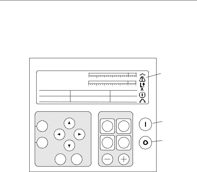
The keypad is a local operator interface that is mounted on the control cabinet door. Refer to Figure 2-4 for a view of the keypad and a summary of the operator and maintenance functions available. Chapter 5 describes the keypad in detail.
gEX2100 Excitation Control |
|
|
|
|
|
FVR Feedback |
|
|
|
|
|
0.0 Volts |
-30% |
0% |
|
100% |
150% |
FldCurrAmps |
|
|
|
|
|
0.00 Amps |
-30% |
0% |
|
100% |
150% |
Vmag |
Imag |
|
Watts |
|
|
0.00 |
0.00 |
|
0.00 |
|
|
Freq_Hz |
Balance Meter |
|
Vars |
|
|
60.00 |
0.00 |
|
0.00 |
|
|
Navigation |
|
|
Exciter Control |
On |
|
|
|
|
|||
Status |
|
|
Reset |
Auto |
|
|
|
Faults |
|
||
|
|
|
|
|
|
Menu |
|
|
Command |
Man |
|
|
|
|
Menu |
|
|
|
|
|
Voltage Level |
Off |
|
Escape |
Enter |
|
|
|
|
|
|
|
|
||
Exciter Health
& State Icons
Run (Green)
Stop (Red)
Display: |
Pushbuttons: |
Status screens provide analog and digital |
Organized into functional groups: |
representation of exciter functions and values. |
Navigation buttons for using the menu |
Menu screens provide text-based access to |
Exciter Control buttons |
parameters, wizards, and faults. |
Run and Stop buttons |
Figure 2-4. Diagnostic Interface – Keypad
Start/stop commands, regulator transfer commands, and regulator activation commands can be issued from the keypad. The keypad also includes meter displays indicating system conditions such as generator MW and MVARs, field current and
voltage, and regulator balance. Diagnostic displays such as the alarm history display provide system information for maintenance and troubleshooting.
2-10 • Chapter 2 Functional Description |
GEH-6632 EX2100 User’s Guide |
Loading...