


 Loading...
GE EPM 7300, EPM 7700, PMCS 6.11a, EPM5200P, GEH-6513 User Manual
...POWER LEADER TM
PMCS 6.11a Interface Toolkit
Installation Guide
GEH-6513
GE Power Management Control System 6.11a
PMCS Interface Toolkit |
Back to Main Menu • i |
Notice
The information contained in this document is subject to change without notice. GE makes no warranty of any kind with regard to this material, including, but not limited to, the implied warranties of merchantability and fitness for a particular purpose. GE shall not be liable for errors contained herein or incidental consequential damages in connection with the furnishing, performance, or use of this material.
This document contains proprietary information which is protected by copyright. All rights are reserved. No part of this document may be photocopied or otherwise reproduced without consent of GE.
Copyright ©2000 - 2002 by GE. Published in a limited copyright sense, and all rights, including trade secrets, are reserved.
Document Edition - First 5/96 Second 5/97 Third 1/98 Fourth 06/98 Fifth 03/99 Sixth 07/99 Seventh 03/00 Eighth 10/00 Ninth 02/01 Tenth 06/01 Eleventh 01/02
The following are products of General Electric Company:
POWER LEADERTM Meter |
239 |
Motor Protection Relay |
GE Fanuc Series 90/30 PLC |
POWER LEADER Modbus Monitor |
269 Plus Motor Management Relay |
GE Fanuc Series 90/70 PLC |
|
POWER LEADER Electronic Power |
369 Motor Management Relay |
Power Quality Meter (PQM) |
|
Meter |
|
|
|
Spectra MicroVersaTrip |
SR469 Motor Management Relay |
EPM 7300 Electronic Power Meter |
|
EPM 7600 Electronic Power Meter |
EPM 7500 Electronic Power Meter |
EPM 7330 Electronic Power Meter |
|
Enhanced MicroVersaTrip-C |
SR489 Generator Management Relay |
EPM 7700 Electronic Power Meter |
|
Enhanced MicroVersaTrip-D |
565 |
Feeder Management Relay |
EPM 3710 Electronic Power Meter |
MDP Overcurrent Relay |
735 |
Feeder Relay |
EPM 3720 Electronic Power Meter |
SR750/SR760 Feeder Management Relay |
SR745 Transformer Management Relay |
Spectra Electronic Control Module |
|
Universal Relay |
EPM7430D/EPM7450D |
Motor Manager II (MMII) |
|
GE-Zenith MX200 (Microprocessor |
GE-Zenith Generator PLC (Series 90- |
EPM5300P/EPM5200P |
|
Controller) |
70) |
|
|
EPM5350P (DMMS350) |
EPM5000P (DMWH300) |
EPM9450Q/EPM9650Q |
|
Electronic Power Meter 3710 , Electronic Power Meter 3720, Electronic Power Meter 7300, Electronic Power Meter 7330, Electronic Power Meter 7500, Electronic Power Meter 7600, and Electronic Power Meter 7700 are products of Power Measurement Limited.
Multilin 269+ Motor Management Relay® is a registered trademarks of Multilin Inc., and Multilin SR489 Generator Management Relay™ and Multilin SR745 Transformer Management Relay™ are trademarks of Multilin Inc.
Microsoft, Microsoft Access, Microsoft Excel, Microsoft PowerPoint, Microsoft Visual Basic, and MS-DOS are registered trademarks, and Windows NT is a trademark of Microsoft Corporation.
Wonderware is a registered trademark of WonderWare Corporation. Wonderware InTouch and NetDDE are trademarks of WonderWare Corporation.
US Pat Nos 5,768,148; 5,764,155; 5,862,391
ii • Back to Main Menu |
PMCS Interface Toolkit |
Back to Main Menu
Contents |
|
INTRODUCTION.............................................................................................................................................................. |
1 |
WELCOME......................................................................................................................................................................... |
1 |
HOW SHOULD I USE THIS MANUAL? .................................................................................................................................. |
2 |
CONVENTIONS .................................................................................................................................................................. |
3 |
ABOUT THE INTERFACE TOOLKIT...................................................................................................................................... |
3 |
INSTALLATION .................................................................................................................................................................. |
3 |
USING AND CONFIGURING PMCS WIZARDS ......................................................................................................... |
5 |
ABOUT THE WIZARDS ....................................................................................................................................................... |
5 |
SMALL FACEPLATE WIZARDS ........................................................................................................................................... |
6 |
Usage ........................................................................................................................................................................... |
6 |
Configuration............................................................................................................................................................... |
6 |
LARGE FACEPLATE WIZARDS............................................................................................................................................ |
8 |
Usage ........................................................................................................................................................................... |
8 |
Configuration............................................................................................................................................................... |
9 |
Special Considerations ................................................................................................................................................ |
9 |
TABULAR DATA SCREEN WIZARDS................................................................................................................................. |
11 |
Usage ......................................................................................................................................................................... |
11 |
Configuration............................................................................................................................................................. |
11 |
ONE-LINE WIZARDS........................................................................................................................................................ |
16 |
Usage ......................................................................................................................................................................... |
16 |
Configuration............................................................................................................................................................. |
17 |
Circuit Breaker One-Line Wizards............................................................................................................................. |
21 |
ELEVATION WIZARDS ..................................................................................................................................................... |
22 |
Usage ......................................................................................................................................................................... |
22 |
Configuration............................................................................................................................................................. |
22 |
FLOOR PLAN WIZARDS ................................................................................................................................................... |
23 |
Usage ......................................................................................................................................................................... |
23 |
Configuration............................................................................................................................................................. |
23 |
TOOLBAR WIZARD.......................................................................................................................................................... |
24 |
Usage ......................................................................................................................................................................... |
24 |
Configuration............................................................................................................................................................. |
24 |
ANNUNCIATOR PANEL WIZARD ...................................................................................................................................... |
25 |
Usage ......................................................................................................................................................................... |
25 |
Configuration............................................................................................................................................................. |
29 |
PMCS Interface Toolkit |
Back to Main Menu • iii |
Troubleshooting Tips for the Annunciator Panel Wizard .......................................................................................... |
34 |
CUSTOM TABLE WIZARD ................................................................................................................................................ |
35 |
Usage ......................................................................................................................................................................... |
35 |
Configuration ............................................................................................................................................................. |
35 |
SYSTEM STATISTICS WIZARD .......................................................................................................................................... |
40 |
Usage ......................................................................................................................................................................... |
40 |
Configuration ............................................................................................................................................................. |
40 |
LOCKOUT/TAGOUT WIZARD ........................................................................................................................................... |
42 |
Usage ......................................................................................................................................................................... |
42 |
Supported Devices...................................................................................................................................................... |
42 |
Configuration ............................................................................................................................................................. |
43 |
Example of Lockout/Tagout Wizard........................................................................................................................... |
44 |
SPECIAL SCRIPTING CONSIDERATIONS FOR THE EPM 7700............................................................................................. |
48 |
Installing the Application Script ................................................................................................................................ |
49 |
EPM 7700 Tabular Data Screen Scripting ................................................................................................................ |
54 |
CREATING FLOOR PLANS, ELEVATION VIEWS, AND ONE-LINE DIAGRAMS ........................................... |
55 |
INTRODUCTION ............................................................................................................................................................... |
55 |
ELEVATION VIEWS .......................................................................................................................................................... |
55 |
FLOOR PLANS.................................................................................................................................................................. |
57 |
ELECTRICAL ONE-LINE DIAGRAMS ................................................................................................................................. |
58 |
CREATING A BASIC INTERFACE ........................................................................................................................................ |
61 |
FEATURES OF GE LARGE FACEPLATE WIZARDS.............................................................................................. |
67 |
ABOUT THE LARGE FACEPLATE WIZARDS ...................................................................................................................... |
67 |
POWER LEADER EPM................................................................................................................................................ |
68 |
SPECTRA MICROVERSATRIP TRIP UNIT .......................................................................................................................... |
71 |
ENHANCED MICROVERSATRIP-C TRIP UNIT .................................................................................................................. |
72 |
ENHANCED MICROVERSATRIP-D TRIP UNIT .................................................................................................................. |
74 |
POWER LEADER METER............................................................................................................................................. |
76 |
SPECTRA ECM................................................................................................................................................................ |
78 |
EPM 3710 METER.......................................................................................................................................................... |
80 |
EPM 3720 METER.......................................................................................................................................................... |
82 |
EPM 7700 METER.......................................................................................................................................................... |
84 |
269 PLUS MOTOR MANAGEMENT RELAY ....................................................................................................................... |
87 |
565 FEEDER MANAGEMENT RELAY ................................................................................................................................ |
92 |
FEATURES OF TABULAR DATA SCREEN WIZARDS........................................................................................... |
99 |
INTRODUCTION ............................................................................................................................................................... |
99 |
FEATURES OF TABULAR DATA SCREENS......................................................................................................................... |
99 |
POWER LEADER EPM ................................................................................................................................................... |
101 |
SPECTRA MICROVERSATRIP ......................................................................................................................................... |
102 |
ENHANCED MICROVERSATRIP-C TRIP UNIT ................................................................................................................ |
103 |
ENHANCED MICROVERSATRIP-D TRIP UNIT ................................................................................................................ |
104 |
POWER LEADER METER........................................................................................................................................... |
105 |
SPECTRA ECM.............................................................................................................................................................. |
106 |
MDP DIGITAL OVERCURRENT RELAY .......................................................................................................................... |
107 |
Monitoring Tab ........................................................................................................................................................ |
107 |
Command Tab .......................................................................................................................................................... |
108 |
Setup Tab ................................................................................................................................................................. |
109 |
PQM (POWER QUALITY METER) .................................................................................................................................. |
110 |
Metering Tab............................................................................................................................................................ |
111 |
Status Tab................................................................................................................................................................. |
112 |
Demand Tab............................................................................................................................................................. |
113 |
IV Range Tab ........................................................................................................................................................... |
114 |
iv • Contents |
PMCS Interface Toolkit |
P Range Tab............................................................................................................................................................. |
115 |
Analysis Tab............................................................................................................................................................. |
116 |
IO Tab ...................................................................................................................................................................... |
117 |
Setpoints Tab............................................................................................................................................................ |
118 |
MOTOR MANAGER II (MMII)....................................................................................................................................... |
119 |
EPM 3710 METER........................................................................................................................................................ |
120 |
EPM 3720 METER........................................................................................................................................................ |
121 |
EPM 7300 METER........................................................................................................................................................ |
122 |
Metering Tab............................................................................................................................................................ |
123 |
Min/Max Tab............................................................................................................................................................ |
124 |
Setup Tab ................................................................................................................................................................. |
125 |
EPM 7330 METER........................................................................................................................................................ |
126 |
Metering Tab............................................................................................................................................................ |
127 |
Min/Max................................................................................................................................................................... |
128 |
Setup Tab ................................................................................................................................................................. |
129 |
EPM 7500/7600 METER............................................................................................................................................... |
130 |
Metering Tab............................................................................................................................................................ |
130 |
Min/Max Tab............................................................................................................................................................ |
132 |
Power Quality Tab................................................................................................................................................... |
133 |
Demand Tab............................................................................................................................................................. |
134 |
Inputs Tab ................................................................................................................................................................ |
135 |
Setup 1 Tab .............................................................................................................................................................. |
136 |
Setup 2 Tab .............................................................................................................................................................. |
138 |
EPM 7700 METER........................................................................................................................................................ |
140 |
Metering Tab............................................................................................................................................................ |
140 |
Min/Max Tab............................................................................................................................................................ |
142 |
Power Quality Tab................................................................................................................................................... |
143 |
Demand Tab............................................................................................................................................................. |
144 |
Inputs Tab ................................................................................................................................................................ |
145 |
Setup 1 Tab .............................................................................................................................................................. |
146 |
Setup 2 Tab .............................................................................................................................................................. |
148 |
UNIVERSAL RELAY ....................................................................................................................................................... |
150 |
Metering Tab............................................................................................................................................................ |
151 |
Power Quality Tab................................................................................................................................................... |
152 |
Protection Control Tab ............................................................................................................................................ |
153 |
Power System Configuration Tab ............................................................................................................................ |
154 |
Transformer Tab ...................................................................................................................................................... |
156 |
Elements Tab............................................................................................................................................................ |
157 |
Digital Counter Tab................................................................................................................................................. |
158 |
Virtual Inputs Tab .................................................................................................................................................... |
159 |
Virtual Outputs Tab ................................................................................................................................................. |
160 |
Contact Inputs Tab................................................................................................................................................... |
161 |
Contact Output Tab.................................................................................................................................................. |
162 |
DCMA Tab ............................................................................................................................................................... |
163 |
Source Tabs.............................................................................................................................................................. |
164 |
Demand Tab............................................................................................................................................................. |
165 |
Line Tab ................................................................................................................................................................... |
166 |
Breaker Tab ............................................................................................................................................................. |
167 |
Contact Output Current States Tab.......................................................................................................................... |
168 |
Remote Temperature Detection Tab ........................................................................................................................ |
169 |
Bus Tab .................................................................................................................................................................... |
170 |
239 MOTOR PROTECTION RELAY.................................................................................................................................. |
171 |
Metering tab............................................................................................................................................................. |
171 |
Status Tab ................................................................................................................................................................ |
172 |
Trip Data.................................................................................................................................................................. |
173 |
PMCS Interface Toolkit |
Contents • v |
Setpoints Tab............................................................................................................................................................ |
174 |
269 PLUS MOTOR MANAGEMENT RELAY ..................................................................................................................... |
175 |
369 MOTOR MANAGEMENT RELAY .............................................................................................................................. |
176 |
Metering Tab............................................................................................................................................................ |
176 |
Alarms Tab............................................................................................................................................................... |
178 |
Demand Tab............................................................................................................................................................. |
179 |
Local RTD Tab......................................................................................................................................................... |
180 |
Remote RTD Tab...................................................................................................................................................... |
181 |
Control Tab .............................................................................................................................................................. |
182 |
Setup Tab ................................................................................................................................................................. |
183 |
SR469 MOTOR MANAGEMENT RELAY.......................................................................................................................... |
184 |
Metering Tab............................................................................................................................................................ |
184 |
Status Tab................................................................................................................................................................. |
185 |
Alarms Tab............................................................................................................................................................... |
186 |
Trip Tab.................................................................................................................................................................... |
187 |
IO Tab ...................................................................................................................................................................... |
188 |
Maintenance Tab...................................................................................................................................................... |
189 |
Analog Tab............................................................................................................................................................... |
190 |
RTD HI Tab.............................................................................................................................................................. |
191 |
Setpoints Tab............................................................................................................................................................ |
191 |
SR489 GENERATOR MANAGEMENT RELAY.................................................................................................................. |
192 |
Metering Tab............................................................................................................................................................ |
192 |
Pickup Tab ............................................................................................................................................................... |
193 |
Alarms Tab............................................................................................................................................................... |
193 |
Trip Data Tab........................................................................................................................................................... |
194 |
IO Tab ...................................................................................................................................................................... |
195 |
Maintenance Tab...................................................................................................................................................... |
196 |
Setpoints Tab............................................................................................................................................................ |
197 |
565 FEEDER MANAGEMENT RELAY .............................................................................................................................. |
198 |
735 FEEDER RELAY ...................................................................................................................................................... |
200 |
Metering Tab............................................................................................................................................................ |
200 |
Trip Data Tab........................................................................................................................................................... |
201 |
Setpoints Tab............................................................................................................................................................ |
202 |
SR745 TRANSFORMER MANAGEMENT RELAY.............................................................................................................. |
203 |
Metering Tab............................................................................................................................................................ |
203 |
Flags Tab ................................................................................................................................................................. |
204 |
IO Tab ...................................................................................................................................................................... |
204 |
Demand Tab............................................................................................................................................................ |
205 |
Harmonic Tab .......................................................................................................................................................... |
206 |
Setpoints Tab............................................................................................................................................................ |
207 |
Power Tab ................................................................................................................................................................ |
208 |
SR750/760 FEEDER MANAGEMENT RELAY .................................................................................................................. |
209 |
Metering Tab............................................................................................................................................................ |
210 |
Status Tab................................................................................................................................................................. |
211 |
Fault Tab.................................................................................................................................................................. |
211 |
Trip Tab.................................................................................................................................................................... |
212 |
Demand Tab............................................................................................................................................................. |
213 |
Logic Tab ................................................................................................................................................................. |
214 |
IO Tab ...................................................................................................................................................................... |
214 |
Setpoints Tab............................................................................................................................................................ |
215 |
FANUC 90/30 ................................................................................................................................................................ |
216 |
FANUC 90/70 ................................................................................................................................................................ |
216 |
FANUC MICRO 90.......................................................................................................................................................... |
217 |
MX200 ......................................................................................................................................................................... |
218 |
Metering Tab............................................................................................................................................................ |
218 |
vi • Contents |
PMCS Interface Toolkit |
Setup Tab ................................................................................................................................................................. |
220 |
GEN PLC..................................................................................................................................................................... |
223 |
Master Tab ............................................................................................................................................................... |
223 |
Generator Tab.......................................................................................................................................................... |
224 |
PSG .......................................................................................................................................................................... |
225 |
EPM5300P................................................................................................................................................................... |
227 |
Metering Tab............................................................................................................................................................ |
227 |
Setup One Tab.......................................................................................................................................................... |
229 |
Setup Two Tab.......................................................................................................................................................... |
230 |
EPM5200P................................................................................................................................................................... |
232 |
Metering Tab............................................................................................................................................................ |
232 |
Setup One Tab.......................................................................................................................................................... |
233 |
EPM5350P................................................................................................................................................................... |
235 |
Metering Tab............................................................................................................................................................ |
235 |
Setup One Tab.......................................................................................................................................................... |
236 |
Setup Two Tab.......................................................................................................................................................... |
237 |
EPM5000P................................................................................................................................................................... |
239 |
Metering................................................................................................................................................................... |
239 |
Setup......................................................................................................................................................................... |
240 |
EPM9450Q/EPM9650Q .............................................................................................................................................. |
241 |
Metering................................................................................................................................................................... |
241 |
Min/Max................................................................................................................................................................... |
242 |
Demand.................................................................................................................................................................... |
243 |
Thermal Average...................................................................................................................................................... |
244 |
Digital Inputs ........................................................................................................................................................... |
245 |
Setup......................................................................................................................................................................... |
246 |
EPM7430D/EPM7450D .............................................................................................................................................. |
247 |
Metering................................................................................................................................................................... |
247 |
Min/Max................................................................................................................................................................... |
248 |
Limits........................................................................................................................................................................ |
249 |
Setup......................................................................................................................................................................... |
251 |
TROUBLESHOOTING ................................................................................................................................................ |
252 |
ASSERTION ERROR........................................................................................................................................................ |
252 |
EPM 3710/EPM 3720 – NO DATA OR INCORRECT DATA DISPLAYED ............................................................................ |
252 |
EPM 3720 – KVAH IMPORT VALUES INCORRECT ........................................................................................................ |
252 |
LONG UPDATE WHEN CHANGING SETPOINTS.................................................................................................................. |
252 |
PLEPM – WRONG METERING TAB DISPLAYED............................................................................................................. |
252 |
INTOUCH APPLICATIONS – WINDOWS NOT DISPLAYED PROPERLY................................................................................. |
253 |
APPENDIX A: EPM 3720 SLIDING WINDOW DEMAND KEYS ......................................................................... |
255 |
DOWNLOADING SLIDING DEMAND WINDOW KEYS TO THE EPM 3720 ......................................................................... |
255 |
APPENDIX B: AUTOMATIC WAVEFORM CAPTURE AND WAVEFORM RETRIEVAL ON EPM3720.... |
263 |
USING A SETPOINT TO TRIGGER WAVEFORM CAPTURE OR RECORD ON THE EPM 3720 ................................................. |
263 |
APPENDIX C: EPM 7700 - SPECIAL CONSIDERATIONS ................................................................................... |
279 |
EPM 7700 TAGS SUBJECT TO DEACTIVATION BY TABULAR DATA SCREEN WIZARD ................................................... |
279 |
INDEX............................................................................................................................................................................. |
293 |
PMCS Interface Toolkit |
Contents • vii |

Introduction
Welcome
The PMCS Interface Toolkit is a POWER LEADER Power Management Control System (PMCS) version 6.11a tool that provides a custom toolkit to efficiently create flexible, accurate, and friendly user interfaces to your power management data. With the PMCS Wizards (accurate graphical representations of power management devices and other commonly encountered objects), you can create applications to provide a customized interface that accurately represents physical, electrical, and geographical plant layouts. The wizards can significantly cut new system development time, providing results in less than an hour.
The PMCS Interface Toolkit allows you to create one-line diagrams, elevation views, and floor plans that you can combine with tabular data screens and three-dimensional device wizards to create a virtual representation of your facility and equipment. With this graphical user interface, you actually see and control devices on the screen, without having to make a trip out to the meter or trip unit.
The Toolkit, which consists of the Wonderware InTouch development environment coupled with GE’s wizards, is easy to use, taking advantage of state-of-the-art drag- and-drop technology. Wizards are provided for all the devices most commonly used with the PMCS DDE Server. Creating a custom interface is as easy as selecting wizards for the devices installed in a facility and placing them on the screen.
Here’s what you’ll find in this guide:
•Chapter 2 explains the kinds of PMCS Wizards, their use and configuration – Small Faceplate wizards, Large Faceplate wizards, Tabular Data Screen wizards, OneLine wizards, Elevation wizards, and Floor Plan wizards.
•Chapter 3 illustrates the use of the GE wizards described in Chapter 2 to create animated displays of the facility floor plan, switchgear elevations, and system oneline diagrams.
•Chapter 4 gives an example of application development, using the wizards described in Chapters 2 and 3 to create an actual PMCS application.
•Chapter 5 describes the functions available with each of the GE Large Faceplate wizards. These wizards are accurate graphical representations
1

of power management devices, complete with working controls that are linked to the corresponding devices in your facility.
•Chapter 6 describes the Tabular Data wizards. These wizards list the data and setpoints of power management devices in a tabular format. Simply point and click to select the appropriate tab of information to display and view the related data.
The examples and references in this guide enable you to create custom interfaces for your PMCS system, and allow you to access power management data in the way that best suits you.
How should I use this manual?
How you use this book depends on your level of expertise with Wonderware
InTouch. Consult the table below to determine where you should start.
If this describes you… |
Start here: |
I’ve never seen this stuff before! What’s |
Refer to the documentation that came with your |
Wonderware InTouch? What are |
Wonderware InTouch package. Start with the |
“Wizards”? |
introduction and tutorial sections, which will teach you |
|
about Wonderware InTouch and how to use it to create |
|
custom applications. When you understand what wizards |
|
are and how to use them, come back here. |
I’ve just opened this package – where do I |
Go to Chapter 1, Introduction. Chapter 1 explains what |
go first? |
the User Screen Configurator is, what it’s good for, and |
|
where to go after that. |
I’m familiar with Wonderware InTouch |
Go to Chapter 1 for installation instructions, then to |
and I’d like to build a custom application |
Chapter 2 for descriptions of the wizards and how to use |
for some GE power management devices. |
them. Chapter 4 provides a demo of actual application |
|
development. This package contains wizards for the |
|
power management devices supported by GE’s PMCS |
|
6.11a software. |
The GE PMCS Wizards are already |
Turn to Chapter 2 for information on how to use the GE |
installed on my system, I’m already |
PMCS Wizards, and Chapter 4 for a quick example of |
experienced with InTouch, and I’m ready |
application development. For detailed descriptions of |
to start building custom applications. |
the Large Faceplate wizards or the Tabular Data Screen |
|
wizards, refer to Chapters 5 and 6 respectively. |
Just tell me about the wizards; I’m an old |
Skim through Chapters 2 and 3 for an overview of |
pro and ready to go! |
what’s in the package, then Chapter 4 for a quick |
|
example of application development. Chapter 5 |
|
describes the GE Large Faceplate wizards and Chapter 6 |
|
the associated Tabular Data Screen wizards. |
|
|
2 |
PMCS Interface Toolkit |
Conventions
You will find this book easy to use if you look for these simple conventions:
•Boldface type indicates the name of an item you need to select.
•Monospace type indicates an example or text that is displayed on the screen.
•UPPERCASE type indicates a file name, command name, or acronym.
About the Interface Toolkit
The Interface Toolkit consists of the Wonderware InTouch development environment and a special set of wizards developed for use with the power management devices supported by PMCS.
Installation
To install the Interface Toolkit from the CD-ROM, refer to the instructions provided in GEH-6514, Read This Book First.
When InTouch is successfully installed, you must add the PMCS wizards to InTouch’s library of available wizards.
To add the wizards to InTouch, start InTouch and enter Development mode. Pull down the Special menu and select Configure > Wizard.
3

From the InTouch Configuration menu, select Install Wizards.
The Wizard Installation dialog displays two list boxes, showing the currently installed wizards and the wizards available for installation. Select the desired wizards from the bottom box and click Install. When the installation is complete, click Done.
Exit from the InTouch Configuration dialog box by clicking OK. The PMCS wizards should now be loaded and ready for use.
4 |
PMCS Interface Toolkit |

Using and Configuring
PMCS Wizards
About the Wizards
The wizards contained in the PMCS Interface Toolkit allow you to quickly build accurate and friendly user interfaces with InTouch. In addition to the various wizards standard with InTouch development systems, the Interface Toolkit provides six types of powerful GE wizards:
•GE Small Faceplates
•GE Large Faceplates
•GE Tabular Screens
•GE One-Line Tools
•GE Elevation Wizards
•GE Floor Plan Wizards
The five-step procedure below outlines how to use InTouch wizards.
1.From InTouch, either create a new window or open an existing window to modify.
2.Select the wizards button  from the floating toolbars. The Wizard Selection dialog box pops up.
3.Select the class of wizard from the list of wizards on the left side of the Wizard Selection dialog. Several classes contain too many devices to fit on one palette and have been broken up into several palettes; for example; Small Faceplates 1 and Small Faceplates 2.
4.Double-click on the desired wizard, then click on the window to place the wizard.
5.Once the wizard has been placed, double-click anywhere on the wizard to open a configuration dialog (if appropriate), and complete any necessary configuration based on the instructions later in this chapter.
The remainder of this chapter is devoted to describing and illustrating the various kinds of wizards included in the PMCS Interface Toolkit.
5

Small Faceplate Wizards
Usage
The Small Faceplate wizards are icon-sized graphics typically used to create accurate elevation views and one-line diagrams. These wizards are provided with logic to open another window, typically either a Large Faceplate or Tabular Data Screen wizard. There are two palettes of Small Faceplates to choose from.
Configuration
In development mode, after placing the Small Faceplate, double-click on the icon to open the Small Faceplate Dialog box, as illustrated below. Typically, a Small Faceplate wizard is linked to a window containing either a Large Faceplate or a Tabular Data Screen wizard. You can move or resize Small Faceplate wizards in the window as desired.
6 |
PMCS Interface Toolkit |

Enter the name of the window to open when the icon is clicked on during runtime.
7

Large Faceplate Wizards
Usage
Large Faceplate wizards are three-dimensional representations of device faceplates that can be used to display data from the device. These three-dimensional wizards include extensive logic that provides an accurate reproduction of the actual display and keys of the device. Large Faceplate wizards are typically placed in overlay windows.
8 |
PMCS Interface Toolkit |

Configuration
Place the Large Faceplate wizard into an open window, then double-click on it to display the Large Faceplate Dialog box. Configure the wizard by entering the appropriate information into each of the boxes.
The figure shown below is the dialog for a typical wizard. Some wizards have additional features which may be configured. See the section titled Features of GE Large Faceplate Wizards for more details.
Enter the unique eight-character name matching the appropriate Topic in the PMCS DDE Server.
Enter the application name of the PMCS DDE Server (GE32MODB or GE32MTCP) for most PMCS devices; ION_LINK for EPM 7700 devices).
Enter the minimum security level for enabling remote command functions.
Enter the name of the window to open when the device display is clicked on during runtime.
You can move and resize Large Faceplate wizards as desired.
Special Considerations
The button controls on the 3-D representation emulate the controls of the actual device. This may be useful for reducing software training time for personnel already familiar with device operation. The detailed features of each of the Large Faceplate wizards are described in the section titled Features of GE Large Faceplate Wizards .
EPM 7700
The EPM 7700 Large Faceplate Dialog box contains an extra field, which must be completed during configuration. The Node Name field requires that you enter the name of the computer running the Communications Server that connects to this particular device. Depending on the configuration of the EPM7700 network, this can be either the Primary node computer, or a computer setup as a "Full Station" Secondary node. Refer to DEH-40035, the GE 7700 Gateway Users Guide, and GEH-6514, PMCS Read This Book First, for more information on network configuration. The Node Name field is required because the EPM7700 does not use the same DDE server as the rest of the standard PMCS devices, and the wizard must be directed to the location of the correct Communications Server for proper configuration of DDE topic names.
9

Also, the Application Name field must be completed as ION_LINK rather than GE32MODB or GE32MTCP for the EPM7700 device. The ION LINK program is installed during initial PMCS 6.11a setup if the EPM7700 software option is selected.
When configuring Wizards on Secondary nodes, the Application Name field entry does not follow the PMCS wizard convention of “\\RemoteComputer\ION_LINK”. EPM7700 Secondary nodes run a local copy of the ION LINK server, thus the application name for EPM7700 Large Faceplate wizards is always “ION_LINK” whether the wizard is installed on the Primary node or a Secondary node. The Node Name entry determines if the wizard is on a Secondary node.
Finally, the EPM 7700 device type requires special InTouch scripting for the large faceplate wizard. Refer to the section at the end of this chapter titled Special Scripting Considerations for the EPM 7700.
10 |
PMCS Interface Toolkit |

Tabular Data Screen Wizards
Usage
Tabular Data Screen wizards contain organized, comprehensive, tabular layouts of device parameters including additional configuration and remote control features. Depending on the device, there may be multiple file-tabs beneath the tabular data section. These switch among various pages relating to data and setpoints.
Each Tabular Data Screen wizard contains buttons for activating the help file, trend window, setup window (if applicable), Event Logger, Waveform Capture, and for closing the window.
You can move and resize Tabular Data Screen wizards as desired.
Configuration
In development mode, after placing a wizard into an open window, double-click on it to display the Tabular Data Dialog box. The figure below shows the dialog box for a typical Tabular Data wizard. Some wizards have additional features which may be configured. See the section titled Features of Tabular Data Screen Wizards for more details.
11

Enter the unique eightcharacter name matching the appropriate Topic in the PMCS DDE Server.
EPM 7700
Use the Group Name field to logically group devices, if desired. Enter the name of the group to which the device belongs.
Enter the application name of the PMCS DDE Server (GE32MODB or GE32MTCP).
Enter the minimum security level for enabling remote command and setup functions.
Enter the name of the window to be opened when the Trend button is clicked on during runtime.
Enter the name of the window to be opened when the Setup button is clicked on during runtime.
The EPM 7700 Tabular Data Dialog box is slightly different from the other PMCS device types, containing two extra fields and requiring minor differences in configuration. The Tabular Data Dialog for the EPM 7700 is shown below, followed by the special configuration requirements.
The Node Name field requires that you enter the name of the computer running the Communications Server that connects to this particular device. Depending on the configuration of the EPM7700 network, this can be either the Primary node computer, or a computer setup as a “Full Station” Secondary node. Refer to DEH-
12 |
PMCS Interface Toolkit |
40035, the GE 7700 Gateway Users Guide, and GEH-6514, PMCS Read This Book First, for more information on network configuration. The Node Name field is required because the EPM7700 does not use the same DDE server as the rest of the standard PMCS devices, and the wizard must be directed to the location of the correct Communications Server for proper configuration of DDE topic names.
Also, the Application Name field must be completed as ION_LINK rather than GE32MODB or GE32MTCP for the EPM7700 device. The ION LINK program is installed during initial PMCS setup if the EPM7700 software option is selected.
When configuring Wizards on Secondary nodes, the Application Name field entry does not follow the PMCS wizard convention of “\\RemoteComputer\ION_LINK”. EPM7700 Secondary nodes run a local copy of the ION LINK server, thus the application name for EPM7700 Tabular Data Wizards is always “ION_LINK” whether the wizard is installed on the Primary node or a Secondary node. The Node Name entry determines if the wizard is on a Secondary node.
The Gateway Name field must be completed with GE77GTWY, the application name of the GE 7700 Gateway Server program. When configuring the EPM7700 Tabular wizard on a Secondary node, the Gateway Name does follow the PMCS wizard convention of “\\RemoteComputer\GE77GTWY” in the Gateway Name field, where ‘RemoteComputer’ is the name of the PC where the GE 7700 Gateway application is running – the Primary Node. The following example shows a Tabular Data Dialog box as it would appear when configuring a Tabular Data wizard on a Secondary node. The Node Name field contains the name of the Primary Node computer, the Application Name field is ION_LINK (as it is for ALL EPM7700 wizards on ANY node) and the Gateway Name field points to the GE 7700 Gateway Server running on the Primary Node PC.
Finally, the EPM 7700 device type requires special InTouch scripting for the tabular data screen wizard. Refer to the section at the end of this chapter titled Special Scripting Considerations for the EPM 7700.
Refer to DEH-40035 for information on the Communications Server and 7700 Gateway Server.
369 Motor Management Relay
The 369 Motor Management Relay offers an optional Remote RTD module, which can provide support for up to 12 additional RTDs. Accordingly, the 369 Tabular
13
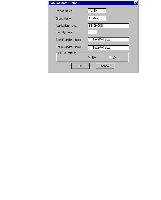
Data Dialog box has an extra field for indicating when the RRTD option is installed. Be sure to select the correct RRTD option when completing the 369's Tabular Data Dialog window. If you are not planning to use an RRTD module with your relay, select the "No" button. This minimizes the number of I/O tags created by the wizard, providing better performance.
14 |
PMCS Interface Toolkit |

Universal Relay
The Universal Relay device comes in several different models, and each model supports different capabilities, which are reflected by the various tabs available for each model. When configuring a Universal Relay device, you first select the UR Model, then choose which tabs will be displayed for the particular device.
The UR devices are also capable of communicating with a different type of PMCS DDE Server than the other PMCS Advanced Wizards. By selecting the UCA/MMS checkbox, you indicate that you wish the UR wizard to retrieve its data for display from the MMS Server whose name is entered in the Application Name field.
Complete the Application Name field; typically GE32MODB or GE32MTCP.
Special Note:
The UCA/MMS is not supported in this version. So don’t Check this checkbox.
Select the Model of UR which you are configuring. This determines the contents of the Available Tabs list.
Highlight the tabs you wish to display on the Tabular Data Screen wizard. Use the control key to select multiple tabs.
15

One-Line Wizards
Usage
You can use one-line wizards to create animated one-line diagrams that represent an electrical schematic of the devices monitored by the software. These wizards are provided with logic to either open another window or display device status.
One-Line wizards are divided into five functional groups according to the type of animation:
•Horizontal and Vertical Meter wizards display another window, such as a 3-D faceplate.
•Transformer, Fuse, Ground Symbol, and Motor Symbol wizards have a discrete color-change animation indicating the On/Off state of the device.
•Horizontal and Vertical Relay wizards also have discrete color-change animation indicating the On/Off state of the device.
•Horizontal and Vertical Switch wizards have four discrete animations; two are color changes indicating the On/Off state of the device and two are used for a three-state display (Open, Closed, and Error conditions).
16 |
PMCS Interface Toolkit |

•Circuit Breaker wizards have two discrete color-change animations for On/Off status display and one analog animation for a five-state display (Open, Closed, Out, Trip, and Error conditions).
•Lockout/Tagout symbols have discrete visibility animations for various tags. Refer to the section Using and Configuring PMCS Wizards: Lockout/Tagout Wizard for more information.
Configuration
In development mode, after placing the one-line device icon, double-click on the icon to open its configuration dialog box. All one-line wizards have two configuration items in common:
•Line Size is a number between 1 and 20 that sets the pixel width of the lines in the wizard.
•Size configuration consists of three radio buttons (Small, Medium, and Large) that determine the overall size of the wizard on the screen.
Use the snap-to-grid feature in InTouch to quickly align One-Line wizards. Configuration of each of the five classes of One-Line wizards is described below.
Meter One-Line Wizards
After placing a meter wizard in a window, double-click on it to display the dialog box shown below. Configure the wizard by entering the appropriate information into each of the boxes.
Enter the name of the window to open when the icon is clicked on during runtime.
Select the color of the meter wizard.
17

Transformer, Fuse, Ground, and Motor One-Line
Wizards
After placing a Fuse, Ground, or Motor wizard in a window, double-click on it to display the dialog box shown below. Configure the wizard by entering the appropriate information into each of the boxes.
Enter the name of the InTouch discrete tag that determines the state of the line colors during runtime.
Specify the colors of the lines when the Bus Status is On and Off. The wizard is displayed in the On Color when the Bus Status Tagname = 1, Off Color when the Bus Status Tagname = 0.
The dialog box for the Transformer wizard has an extra check box that specifies either an air-core or iron-core transformer, as shown below.
Click on the check box to specify an air-core transformer.
18 |
PMCS Interface Toolkit |
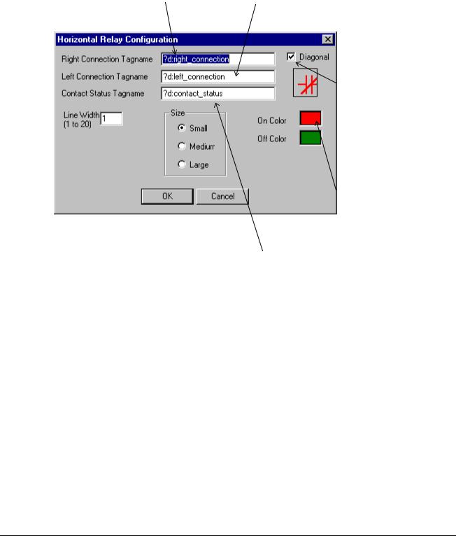
Horizontal and Vertical Relay One-Line Wizards
After placing a Horizontal or Vertical Relay wizard in a window, double-click on it to display the dialog box shown below. Configure the wizard by entering the appropriate information into each of the boxes.
Enter the name of the InTouch discrete tag that determines the color of the line to the right (or top) of the relay symbol during runtime.
Enter the name of the InTouch discrete tag that determines the color of the line to the left (or bottom) of the relay symbol during runtime.
Click the check box to display a slash through the contacts (normally closed contact).
Specify the colors of the wizard elements when the contact status and connection discrete tags are On or Off.
Enter the name of the InTouch discrete tag that determines the color of the relay symbol during runtime.
19

Horizontal and Vertical Switch One-Line Wizards
After placing a Horizontal or Vertical Switch wizard in a window, double-click on it to display the dialog box shown below. Configure the wizard by entering the appropriate information into each of the boxes.
Enter the name of the InTouch discrete tag that determines the color of the line to the right (or top) of the switch symbol during runtime.
Enter the name of the InTouch discrete tag that determines the color of the line to the left (or bottom) of the switch symbol during runtime.
Enter the names of the InTouch discrete tags that determine the state of the switch during runtime.
Specify the colors of the wizard elements when the connection and switch discrete tags are On and Off and when there is an Error condition. The switch symbol color is determined by the following logic:
SwOpen |
SwClosed Color |
||||
|
|
0 |
|
|
|
0 |
error |
|
|||
0 |
1 |
on |
|||
1 |
0 |
off |
|||
1 |
1 |
error |
|||
|
|
|
|
|
|
20 |
PMCS Interface Toolkit |
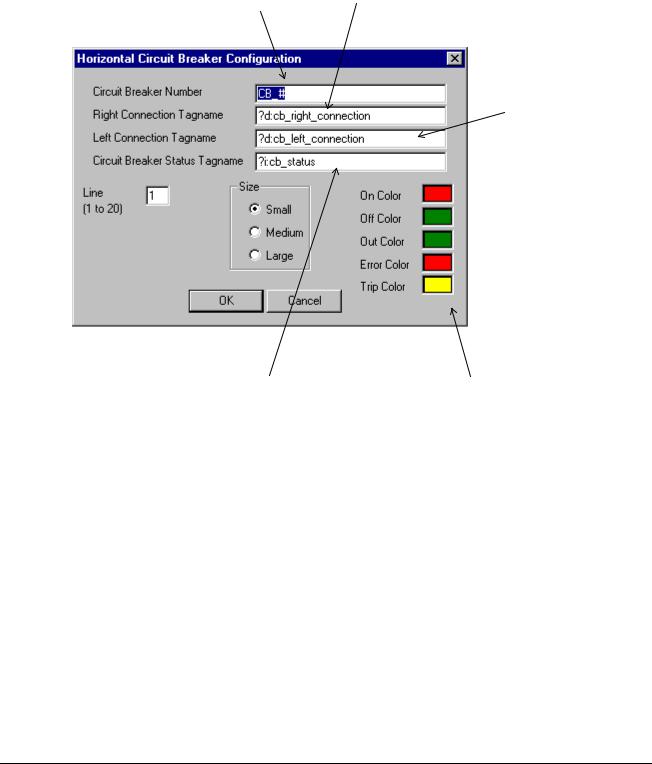
Circuit Breaker One-Line Wizards
After placing a Horizontal or Vertical Circuit Breaker wizard in a window, doubleclick on it to display the dialog box shown below. Configure the wizard by entering the appropriate information into each of the boxes.
Enter text to display next to the breaker graphic during runtime (optional).
Enter the name of the InTouch discrete tag that determines the color of the line to the right (or top) of the breaker symbol during runtime.
Enter the name of the InTouch discrete tag that determines the color of the line to the left (or bottom) of the breaker symbol during runtime.
Enter the name of the InTouch analog tag that determines the color of the circuit breaker symbol, the state of the breaker, and the status text displayed next to the breaker icon during runtime.
Specify the colors of the wizard elements and status text for the breaker states during runtime.
See the table below for default status/color mappings.
The breaker status values and the associated default colors are listed in the table below. Error status indicates that the breaker status inputs create an indeterminate state for the breaker.
Breaker Status |
Value |
Text |
Default Color |
|
|
|
|
Open |
1 |
OPN |
Green |
|
|
|
|
Closed |
3 |
CLD |
Red |
|
|
|
|
Drawn Out |
5 |
OUT |
Green |
|
|
|
|
Tripped |
7 |
TRP |
Yellow |
|
|
|
|
Error |
9 |
ERR |
Flashing Red |
|
|
|
|
Breaker status values & display colors.
21

Elevation Wizards
Usage
Elevation wizards are graphical elements that represent switchgear components useful for creating 3-D elevation views. These wizards are not associated with any logic or animation, but are provided to create more visually accurate screens and representations of equipment. Device icon wizards are typically placed on the Elevation wizards to show the breakers, trip units, and meters and provide navigation to device 3-D wizards, tabular displays, or arbitrary windows.
Configuration
After placing an Elevation wizard in an open window, it may be moved or resized, but no other configuration is possible. Elevation wizards are not provided with logic for opening another window.
22 |
PMCS Interface Toolkit |
Loading...