


GE ESS22, ESS25, GSS25, GSS22, GSS20 User Manual
...GE Consumer Home Services Training
TECHNICAL SERVICE GUIDE
General Electric Side-by-Side
Knob Control/Metal Liner Refrigerator
MODEL SERIES:
GSS20
GSS22
GSS25
ESS22
ESS25
HSS22
HSS25
SSS25
PUB # 31-9071 02/01

!
IMPORTANT SAFETY NOTICE
The information in this service guide is intended for use by individuals possessing adequate backgrounds of electrical, electronic, and mechanical experience. Any attempt to repair a major appliance may result in personal injury and property damage. The manufacturer or seller cannot be responsible for the interpretation of this information, nor can it assume any liability in connection with its use.
WARNING
To avoid personal injury, disconnect power before servicing this product. If electrical power is required for diagnosis or test purposes, disconnect the power immediately after performing the necessary checks.
RECONNECT ALL GROUNDING DEVICES
If grounding wires, screws, straps, clips, nuts, or washers used to complete a path to ground are removed for service, they must be returned to their original position and properly fastened.
GE Consumer Home Services Training
Technical Service Guide
Copyright © 2001
All rights reserved. This service guide may not be reproduced in whole or in part in any form without written permission from the General Electric Company.

Table of Contents
Introduction . . . . . . . . . . . . . . . . . . . . . . . . . . . . . . . . . . . . . . . 2
Installation . . . . . . . . . . . . . . . . . . . . . . . . . . . . . . . . . . . . . . . . 3
Specifications . . . . . . . . . . . . . . . . . . . . . . . . . . . . . . . . . . . . . . 4
Nomenclature . . . . . . . . . . . . . . . . . . . . . . . . . . . . . . . . . . . . . . 5
Warranty Information . . . . . . . . . . . . . . . . . . . . . . . . . . . . . . . . . . 6
Operating Characteristics . . . . . . . . . . . . . . . . . . . . . . . . . . . . . . . 7
General Locator Views. . . . . . . . . . . . . . . . . . . . . . . . . . . . . . . . 13
Mechanical Disassembly . . . . . . . . . . . . . . . . . . . . . . . . . . . . . . 15
Diagnostics . . . . . . . . . . . . . . . . . . . . . . . . . . . . . . . . . . . . . . 32
Component and Connector Locator Views . . . . . . . . . . . . . . . . . . . . 50
Schematics . . . . . . . . . . . . . . . . . . . . . . . . . . . . . . . . . . . . . . 54
Illustrated Parts Catalog . . . . . . . . . . . . . . . . . . . . . . . . . . . . . . . 58
– 1 –

Introduction
2001 Energy SxS models are being introduced in response to the requirement for more energyefficient refrigerators by mid year 2001, along with having feature and operation enhancements. The primary differences in this refrigeration system are the adaptive defrost system (see Pub. # 31-9062), control board, software, and control systems that operate independently in fresh food and freezer sections. The new high-efficiency control system has the ability to cycle components and adjust fan speeds as required to maintain temperaturesetting ranges in freezer and fresh food sections. Feedback systems are digital inputs and relay outputs. Sensors (thermistors) are used to measure temperature with communications to a main PC board, which controls the unit components. The refrigerator has versions that have control knobs or touchpads (Profile models) to provide inputs to a microprocessor. The freezer/ fresh food controls are temperature setpoint type and have settings of 0-9 with 9 being the coldest temperature possible. The new NO CLEAN condenser is serviceable from the rear and is designed to prevent the customer from having to clean the condenser in normal usage conditions.
Sealed system operation and compressor are functionally the same as previous models, with some minor changes.
The 20', 22', and 25' side-by-side models are the models affected. These models are available with through-the-door chilled water and ice dispenser, and built-in water filter feature. On models
requiring icemaker, the newest electronic icemaker (see Pub. # 31-9063) has been or can be installed.
The freezer has adjustable shelves, slide-out Spillproof shelf, QuickSpace shelf, and deep door shelves, based on model. The fresh food section has a baking soda holder, fruit and vegetable drawer, drawer dividers, adjustable humidity drawer, and convertible meat drawer.
This new high-efficiency refrigerator is a combination of the most efficient refrigeration system and the most desirable customer features available.
– 2 –

Installation
ATTENTION INSTALLER:FOR A QUALITY INSTALLATION, FOLLOW THESE INSTRUCTIONS.
ROLLERS
HEX-HEAD BOLTS (4)
•REMOVE AND DISCARD SKIDBOARDS and bolts used to hold skidboards.
•Use PADDED HAND TRUCK to protect refrigerator finish.
,,,,,@@@@@€ААААА€€€€
CARDBOARD PROTECTS DOOR EDGES
MAKE SURE FRONT ROLLERS DO NOT REST ON TRUCK
RAISE
|
DO NOT |
|
|
OVER- |
|
,@€À |
TIGHTEN |
|
STRAP |
||
|
ROLLER
ADJUSTMENT
TRUCK FROM
SIDE ONLY
•ADJUST FRONT ROLLERS
so that refrigerator is solid and doors close easily.
• LEAVE TAPE ON DOORS until |
• MAKE SURE DOORS ARE EVEN |
refrigerator is in its final location. |
AT TOP. Check gasket seal. |
9 IS COLDEST
0 IS OFF
4 |
5 |
6 |
4 |
5 |
6 |
3 |
|
7 |
3 |
|
7 |
2 |
|
8 |
2 |
|
8 |
|
|
|
|
||
1 |
|
9 |
1 |
|
9 |
0 |
|
|
|
|
|
FREEZER |
FRESH FOOD |
||||
•SET BOTH CONTROLS TO “5”.
•SET ICEMAKER TO OFF until
water line is connected.
•IMPORTANT: IMMEDIATELY REMOVE ALL CLEAR PROTECTIVE TAPE FROM TRIM.
•TO REMOVE TAPE RESIDUE AND HANDPRINTS, USE APPLIANCE POLISH.
•REMOVE ALL TAPE AND OTHER PACKAGING MATERIAL FROM INSIDE REFRIGERATOR. DO NOT REMOVE SERIAL PLATE.
IF NECESSARY TO REMOVE DOORS, REMOVE ALL HINGES. FOR DISPENSER MODELS:
TUBING CLIP
COLLAR
PRESS THE WHITE COLLAR AS YOU PULL OUT THE TUBING.
•At lower left hinge, remove tubing from the clip.
•Disconnect the water line.
WHEN INSTALLING DOORS... |
HINGE COVER |
5⁄8″ – 3⁄4″ |
|
• Push tubing into connector |
WIRING |
(5⁄8″ to 3⁄4″ ) to prevent leakage. |
CONNECTORS |
•At upper hinges, disconnect wiring connectors.
•Remove both hinges with each door to prevent damage to tubing or wiring.
TO REINSTALL DOORS...
ALIGN DOORS EVENLY |
FRESH FOOD HINGE |
AT TOP |
ADJUSTMENT PIN |
•Reinstall lower hinges and tighten hinge screws firmly.
•Place door on lower hinge pin and install upper hinges. Tighten upper hinge screws firmly.
•Align both doors evenly at top by adjusting pin on lower fresh food hinge.
•Reconnect wiring connectors and reinstall hinge covers.
•Reinstall tubing by pushing tubing into connector.
•Put tubing back into clip.
FRANÇAIS • ESPANOL
PREFERRED
METHOD
MAKE SURE PROPER
GROUND EXISTS
BEFORE USE
TEMPORARY METHOD (Adapter plugs not  permitted in Canada)
ENSURE PROPER
GROUND AND
FIRM CONNECTION
BEFORE USE
IMPORTANT: PLEASE READ CAREFULLY
FOR PERSONAL SAFETY, THIS APPLIANCE MUST BE PROPERLY GROUNDED.
The power cord of this appliance is equipped with a three-prong (grounding) plug that mates with a standard three-prong (grounding) wall receptacle to minimize the risk of electric shock hazard from this appliance. The customer should have the wall receptacle and circuit checked by a qualified electrician to make sure the receptacle is properly grounded.
Where a standard two-prong wall receptacle is encountered, it is the personal responsibility and obligation of the customer to have it replaced with a properly grounded three-prong wall receptacle.
DO NOT, UNDER ANY CIRCUMSTANCES, CUT OR REMOVE THE THIRD (GROUND) PRONG FROM THE POWER CORD.
USAGE SITUATIONS WHERE THE APPLIANCE’S POWER CORD WILL BE DISCONNECTED INFREQUENTLY
Because of potential safety hazards under certain conditions, we strongly recommend against the use of an adapter plug. However, if you still elect to use an adapter, where local codes permit, a TEMPORARY CONNECTION may be made to a properly grounded two-prong wall receptacle by the use of a UL listed adapter which is available at most hardware stores. The larger slot of the adapter must be aligned to provide proper polarity in the connection of the power cord.
CAUTION: Attaching the adapter ground terminal to the wall receptacle cover screw does not ground the appliance unless the cover screw is metal, and not insulated, and the wall receptacle is grounded through the house wiring. The customer should have the circuit checked by a qualified electrician to make sure the receptacle is properly grounded. When disconnecting the power cord from the adapter, always hold the adapter with one hand. If this is not done, the adapter ground terminal is very likely to break with repeated use. Should this happen, DO NOT USE the appliance until a proper ground has again been established.
USAGE SITUATIONS WHERE THE APPLIANCE’S POWER CORD WILL BE DISCONNECTED FREQUENTLY
Do not use an adapter plug in these situations because frequent disconnecting of the power cord places undue strain on the adapter and leads to eventual failure of the adapter ground terminal. The customer should have the two-prong wall receptacle replaced with a three-prong (grounding) receptacle by a qualified electrician before
using the appliance.
197D3266P001 31-5087 9-00 JR
– 3 –

Specifications
– 4 –
Nomenclature
|
|
|
|
|
|
ENGINEERING |
|
|
|
|
|
|
|
NOMENCLATURE |
|
|
|
|
|
|
|
A = INIITIAL DESIGN |
|
|
|
|
|
|
|
|
|
CONFIGURATION |
|
VOLUME |
|
MODEL YEAR |
|
B = 1ST REVISION |
DOOR TYPE |
S = SIDE-BY-SIDE REF. |
|
20 / 22 / 25 CU. FT. |
|
M = 2001 |
|
ETC. |
F = FLAT DOOR |
G S S 2 5 I F M A F W W
BRAND/PRODUCT |
|
DEPTH/POWER |
|
INTERIOR/SHELVES |
|
ICEMAKER/EXTERIOR |
|
EXTERIOR COLOR |
G = GE |
|
S = STANDARD DEPTH |
|
A = LEADER WIRE |
|
B = NON-DISPENSER / ICE-MAKER READY |
|
WW= WHITE/WHITE |
H = HOTPOINT |
|
T = TROPICAL |
|
D = DELUXE WIRE |
|
D = CUBED ICE / WATER |
|
AA = ALMOND/ALMOND |
P = PROFILE (GE) |
|
G = GLOBAL |
|
I = DELUXE GLASS |
|
E = CUBED & CRUSHED ICE / WATER |
|
BB = BLACK/BLACK |
E = ETERNA (GE) |
|
|
|
K = SPILL PROOF/SLIDE-OUT |
|
F = 6 MO. FILTER / CUBED & CRUSHED ICE |
|
CC = BISQUE/BISQUE |
|
|
|
|
|
||||
R = RCA |
|
|
|
GLASS |
|
G = 1 YR. FILTER / CUBED & CRUSHED ICE |
|
WH = WHITE/BLACK |
|
|
|
|
|
|
|||
S = SELECT (GE) |
|
|
|
M = SPILL PROOF/SLIDE-OUT |
|
I = IN-LINE FILTER / INDICATOR & C/C/W |
|
AD = ALMOND/BLACK |
|
|
|
GLASS & QUICK SPACE |
|
|
|||
|
|
|
|
|
|
|
|
|
|
|
|
|
|
|
|
||
|
|
|
|
Q = SHOWCASE DERIVATIVE |
|
|
|
|
|
|
|
|
U = AVB DERIVATIVE |
|
|
|
|
|
|
|
|
W= HPS (CONTRACT) |
|
|
|
|
|
|
|
|
DERIVATIVE |
|
|
|
|
|
|
|
|
X = REGIONAL DERIVATIVE |
|
|
|
GEA00687 |
|
|
|
|
|
|
|
|
Note: Mini Manual/Tech Data Sheet is located in a plastic bag in the control console.
– 5 –

Warranty Information
Sales slip or cancelled check is required as proof of original purchase date to obtain service under warranty. Note: Water filter cartridge warranty is 30 days.
All warranty service is provided by our Factory Service Centers or an authorized Customer Care® technician.
For The Period Of: |
GE Will Replace: |
|
|
One Year |
Any part of the refrigerator which fails due to a defect in |
From the date of the original |
materials or workmanship. During this full one-year warranty, |
purchase |
GE will also provide, free of charge, all labor and in-home |
|
service to replace the defective part. |
|
|
Five Years |
Any part of the sealed refrigerating system (the |
From the date of the original |
compressor, condenser, evaporator, and all connecting |
purchase |
tubing) which fails due to a defect in materials or |
|
workmanship. During this five-year warranty, GE will also |
|
provide, free of charge, all labor and in-home service to |
|
replace the defective partin the sealed refrigerating system.t. |
|
|
Lifetime |
Any see-through pan or drawer furnished with the |
From the date of the original |
refrigerator if the pan or drawer breaks during normal |
purchase |
household use. Drawer covers are not included. During |
|
this limited lifetime warranty, you will be responsible for |
|
any labor or in-home service costs. |
|
|
What GE Will Not Cover:
•Service trips to your home to teach you how to use the product.
•Improper installation.
•Failure of the product if it is abused or used for other than the intended purpose or used commercially.
•Loss of food due to spoilage.
•Replacement of house fuses or resetting of circuit breakers.
•Replacement of the water filter cartridge due to water pressure that is outside the specified operating range or due to excessive sediment in the water supply.
•Replacement of water filter cartridge after its expected useful life, 30 days.
•Damage to the product caused by accident, fire, floods, or acts of God.
•Incidental or consequential damage caused by possible defects with this appliance.
This warranty is extended to the original purchaser and any succeeding owner for products purchased for home use within the USA. In Alaska, the warranty excludes the cost of shipping or service calls to your home.
Some states do not allow the exclusion or limitation of incidental or consequential damages. This warranty gives you specific legal rights, and you may also have other rights which vary from state to state. To know what your legal rights are, consult your local or state consumer affairs office or your state’s Attorney General.
Warrantor: General Electric Company. Louisville, KY 40225
– 6 –

Operating Characteristics
Table of Contents
Normal Operating Characteristics That Are Different from Previous Models . . 8 Abnormal Operating Characteristics (Incorrect Operation) . . . . . . . . . . . . . . . 8 Adaptive Defrost . . . . . . . . . . . . . . . . . . . . . . . . . . . . . . . . . . . . . . . . . . . . . . . . . . 8 Cooling Operation (Adaptive Defrost) . . . . . . . . . . . . . . . . . . . . . . . . . . . . . . . . 8 Pre-Chill Operation (Adaptive Defrost) . . . . . . . . . . . . . . . . . . . . . . . . . . . . . . . . 8 Defrost Heater Operation (Adaptive Defrost) . . . . . . . . . . . . . . . . . . . . . . . . . . . 9 Dwell Period (Adaptive Defrost) . . . . . . . . . . . . . . . . . . . . . . . . . . . . . . . . . . . . . 9 Post Dwell (Adaptive Defrost) . . . . . . . . . . . . . . . . . . . . . . . . . . . . . . . . . . . . . . . 9 Liner Protection Mode . . . . . . . . . . . . . . . . . . . . . . . . . . . . . . . . . . . . . . . . . . . . . 9 Dispensing Functions . . . . . . . . . . . . . . . . . . . . . . . . . . . . . . . . . . . . . . . . . . . . . . 9 Dispenser Light . . . . . . . . . . . . . . . . . . . . . . . . . . . . . . . . . . . . . . . . . . . . . . . . . . . 9 Dispenser Lock . . . . . . . . . . . . . . . . . . . . . . . . . . . . . . . . . . . . . . . . . . . . . . . . . . . 10 Filters . . . . . . . . . . . . . . . . . . . . . . . . . . . . . . . . . . . . . . . . . . . . . . . . . . . . . . . . . . . 10 Hinge System and Door Closure . . . . . . . . . . . . . . . . . . . . . . . . . . . . . . . . . . . . . 10 Airflow (Cabinet Interior) . . . . . . . . . . . . . . . . . . . . . . . . . . . . . . . . . . . . . . . . . . . 11 “Jelly Roll” Condenser . . . . . . . . . . . . . . . . . . . . . . . . . . . . . . . . . . . . . . . . . . . . . 11 Main Control Board . . . . . . . . . . . . . . . . . . . . . . . . . . . . . . . . . . . . . . . . . . . . . . . . 12
– 7 –

Normal Operating Characteristics That Are Different from Previous Models
•Icemaker auger rotates clockwise.
•Evaporator fan running, without compressor or condenser fan.
•Post Dwell (Adaptive Defrost), compressor, and condenser fan on with evaporator fan off after defrost cycle.
•Liner Protection Mode, fan comes on when the doors are open for 3 minutes.
•Evaporator fan and compressor can run continuously for 2 hours (Adaptive Defrost).
•Different sound levels can be heard when the fan changes speed.
•Response time for drastic temperature change is 2 to 10 minutes. The main control board will only respond to 8 degrees (Fahrenheit) of temperature change per minute as determined by resistance of sensor.
Abnormal Operating Characteristics
(Incorrect Operation)
•Evaporator fan on, compressor off, and damper shut (except liner protection mode).
•Rapid fan speed changes, fan takes at least 1 minute to change speeds.
•Compressor running without the condenser fan. The compressor and condenser fan should always run at the same time.
Adaptive Defrost
Adaptive Defrost can be described as a defrost system that adapts to a refrigerator’s surrounding environment and household usage.
Unlike conventional defrost systems that use electromechanical timers with a fixed defrost cycle time, Adaptive Defrost utilizes an intelligent, electronic control to determine when the defrost cycle is necessary. In order to accomplish the correct defrost cycle time, the main control board monitors the following refrigerator operations:
•Length of time the refrigerator doors were open since the last defrost cycle.
•Length of time the compressor has run since the last defrost cycle.
•Amount of time the defrost heaters were on in the last defrost cycle.
Adaptive Defrost is divided into 5 separate cycles. Those operations are:
•Cooling Operation
•Pre-Chill Operation
•Defrost Heater Operation
•Dwell Period
•Post Dwell
(See Pub. #31-9062 for more information on Adaptive Defrost.)
Cooling Operation (Adaptive Defrost)
During the cooling operation, the main control board monitors door opening (fresh food and freezer doors) and compressor run times. The board counts the time the doors are open. It reduces the length between defrosts by 255 seconds (multiplication factor) for each second that each door is open. If both doors are open, it reduces it by twice the amount. The multiplication factor reduces compressor run time. If the doors are not opened, the compressor will run up to 60 hours between defrosts. If the doors are opened frequently and/or for long periods of time, the compressor run time between defrosts will be reduced to as little as 8 hours.
Pre-Chill Operation (Adaptive Defrost)
F |
F˚ / C˚ |
PRE-CHILL MODE |
|
|
|
|
|
|||||
R |
|
|
|
|
|
|
|
|
|
|
||
|
|
|
|
|
|
|
|
|
|
|
||
E |
25˚ / -4˚ |
|
|
|
|
|
|
|
|
|
|
|
E |
|
|
|
|
|
|
|
|
|
|
|
|
Z |
20˚ / -7˚ |
|
|
|
|
|
|
|
|
|
|
|
E |
|
|
|
|
|
|
|
|
|
|
||
|
|
|
|
|
|
|
|
|
|
|
||
R |
15˚ / -9˚ |
|
|
|
|
|
|
|
|
|
|
|
|
|
|
|
|
|
|
|
|
|
|
||
A |
10˚ / -12˚ |
|
|
|
|
|
|
|
|
|
|
|
I |
|
|
|
|
|
|
|
|
|
|
||
R |
|
|
|
|
|
|
|
|
|
|
|
|
T |
5˚ / -15˚ |
|
|
|
|
|
|
|
|
|
|
|
|
|
|
|
|
|
|
|
|
|
|
||
E |
0˚ / -18˚ |
|
|
|
|
|
|
|
|
|
|
|
M |
|
|
|
|
|
|
|
|
|
|
||
08:00 |
09:00 |
10:00 |
11:00 |
12:00 |
13:00 |
14:00 |
15:00 |
16:00 |
17:00 |
18:00 |
||
P |
||||||||||||
-5˚ / -21˚ |
|
|
|
|
|
|
|
|
|
|
||
E |
|
|
|
|
|
|
|
|
|
|
||
R |
-10˚ / -23˚ |
|
|
|
|
|
|
|
|
|
|
|
A |
|
|
|
|
|
|
|
|
|
|
||
T |
|
|
|
|
|
|
|
|
|
|
|
|
U |
-15˚ / -26˚ |
|
|
|
|
|
|
|
|
|
|
|
R |
|
|
|
|
|
|
|
|
|
|
|
|
SE |
-20˚ / -29˚ |
|
|
|
|
|
|
|
|
|
|
|
Pre-Chill Defrost
When the main control board determines that defrost is necessary, it will force the refrigerator
– 8 –
into a continuous cool mode (pre-chill). During prechill, the freezer temperature may be driven below the set point. However, the fresh food temperature will be regulated by the damper. Pre-chill will last for 2 hours. These models do not have a defrost holdoff.
Defrost Heater Operation (Adaptive
Defrost)
After 2 hours of pre-chill operation, the main control board turns off the compressor, condenser fan, and evaporator fan.
During defrost operation, the main control board monitors the evaporator temperature using evaporator thermistor inputs. The thermistor will terminate defrost heater operation in less than 45 minutes. Typical defrost time is 20-30 minutes. Maximum defrost cycle is 45 minutes with heater on, 5 minutes in dwell.
The defrost system is protected by a defrost safety thermostat (switch). The thermostat opens when the evaporator temperature raises to 140° F and closes when the evaporator temperature lowers to 110° F.
Dwell Period (Adaptive Defrost)
After defrost heater operation has been terminated by the main control board, a 5-minute dwell period occurs. During this period, the compressor, condenser fan, and the evaporator fan remain off. The remaining frost melting from the evaporator will continue to drip and drain so that prior to the cooling operation, the evaporator will be totally clear of any moisture. After the 5-minute dwell period, the unit goes into post dwell.
Post Dwell (Adaptive Defrost)
The post dwell period is designed to cool the evaporator before circulating air within the refrigerator. This prevents any residual heat on the evaporator from being distributed in the freezer. During this period, the compressor is on and the condenser fan is on, but the evaporator fan is off, and the damper is closed. Post dwell lasts 10 minutes on these models.
Liner Protection Mode
The liner protection mode will activate if either of the doors have been open for 3 minutes. This mode will start the evaporator fan and close the damper.
This mode is controlled by 2 timers. Timer #1 monitors door-open time. A 3-minute door-open count begins when the door is opened. If 3 minutes elapse before the door is closed, the liner protection mode will become active. Once the door is closed, timer #1 resets and liner protection mode goes into standby. In standby, normal fan and damper operations resume and timer #2 begins a 3-minute door-closed count. If 3 minutes elapse without a door opening, liner protection mode will completely deactivate. If a door is opened within the timer #2 door-closed count, the remaining time in the door-closed count will be deducted from the timer #1 door-open count.
Dispensing Functions
The water, crushed ice, and cubed ice functions are controlled by the main control board. To select a function, press the appropriate pad on the dispenser. The LED will light to identify the selection.
To dispense the selected item, depress the dispenser cradle located in the dispenser recess. The solenoid and linkage assembly will open the ice chute door to dispense the ice. If cubed ice is selected, the crushed ice bypass solenoid will allow cubed ice to bypass the ice crusher. The ice chute door must remain open for 5 second after dispensing ceases. After this 5 second delay, the solenoid and linkage assembly will shut the ice chute door.
The dispenser light will come on automatically when the dispenser cradle is depressed and will fade out 5 seconds after it is released.
Dispenser Light
The LIGHT pad turns the dispenser light on and off. When the light is turned off, it will fade out. The dispenser light will come on automatically when the dispenser cradle is depressed and will fade out 5 seconds after it is released. The LIGHT pad will not turn off the light during dispense.
– 9 –

Dispenser Lock |
Hinge System and Door Closure |
When the dispenser system is locked, no dispenser command will be accepted. This includes the dispenser cradle and will prevent accidental dispensing that may be caused by children or pets. If a pad is pressed with the system locked, it will be acknowledged with 3 pulses of the LOCK LED accompanied by an audible tone.
To lock or unlock communication between the dispenser and main control board, press the LOCK pad and hold it for 3 seconds. The LOCK LED will flash while the LOCK pad is pressed. When the communication is locked, the LOCK LED will be illuminated.
The status of other functions selected prior to the initiation of the lock feature will be displayed. If the lock is engaged while a mode is active, the LED will remain on until that mode times out.
If the lock is engaged when the filter timer expires, the LED will come on but cannot be reset until the lock is turned off.
The lock feature will be restored in the event of a power disruption.
Filters
Some models are equipped with a water filter located in the upper right-hand corner of the fresh food compartment. The filter is designed to be used for up to 8 hours of open valve time or 1 year of calendar time.
When 90% of filter time (dependant on model) has elapsed (open valve time or calendar time, whichever comes first), the main control board will illuminate the filter reminder LED (amber). When 100% of the filter time has elapsed, the main control board will illuminate the filter reminder LED (red).
Cam with 
Thimble
Screw
Cam Riser
Hinge
Adjustment
Pin
Hinge |
GEA00909 |
The hinge brackets are not adjustable on the cabinet. The fresh food door can be adjusted up and down by using the hinge adjustment pin (located on the fresh food lower door hinge).
The fresh food and freezer lower door hinges are equipped with replaceable cam risers. The cam risers assist in door closure. If the fresh food door is adjusted too high, cam riser will not be engaged, and the fresh food door will not close properly.
IMPORTANT: The refrigerator rollers must be adjusted correctly for proper door closure. When the rollers are adjusted correctly, the door should close easily when open approximately 45 degrees (halfway)
– 10 –

Airflow (Cabinet Interior) |
“Jelly Roll” Condenser |
The freezer compartment is designed so that when the evaporator fan is operating, air is drawn into the bottom of the air tunnel and through the evaporator. The cold air is then pushed out into the top of the freezer.
The fresh food compartment receives chilled air via an electronic damper positioned at the top, rear of the refrigerator between the freezer compartment and the fresh food compartment. The damper is controlled by the main control board and when open, allows chilled air from the freezer air tunnel to move into the fresh food compartment.
Air returns from the fresh food compartment to the freezer compartment via a vent located to the left of the FRESH PRODUCE drawer.
The new NO CLEAN condenser is accessed from the rear and is designed to be tolerant of up to 2 inches of lint. The idea is that the consumer, in normal operating conditions, will never have to clean the condenser. If necessary, only an ordinary appliance brush is used. Air is drawn in from the outside diameter of the condenser and pulled out by the condenser fan. A condenser fan baffle is located at the rear to direct airflow through the condenser. Functionally, the condenser does the same job as previous models. Air is drawn in from front left and rear left and exits out front right side of refrigerator.
– 11 –

Main Control Board
INPUTS |
ACCUMULATED FF AND FRZ |
DOOR OPENINGS (MINUTES) |
COMPRESSOR RUN TIME |
(MINUTES) |
DEFROST HEATER ON TIME |
(MINUTES) |
OUTPUTS |
COOLING |
PRE-CHILL |
DEFROST |
|
|
COMMUNICATION |
DAMPER |
ENCODER |
|
|
THERMISTOR |
|
MODEL |
|
|||||
|
|
INPUT/OUTPUT |
COILS |
INPUTS |
|
|
INPUTS |
|
|
SELECT |
|
||||
|
|
|
|
|
|
|
|
|
|
|
|
|
|
||
COMM +12V -COM |
DI DO |
|
|
|
|
|
|
|
|
|
|
|
|
|
|
1 2 3 4 5 |
|
|
|
|
|
|
|
|
|
|
|
|
|
|
|
|
|
1 |
5 |
1 |
|
J3 |
10 |
1 |
|
|
J1 |
|
9 |
|
|
|
|
|
J4 |
|
|
|
|
|
|
|
|
|
|
||
|
|
|
|
|
|
|
|
|
|
|
|
|
|
1 |
6 |
|
|
|
|
|
|
FAN OUTPUTS |
|
|
|
|
|
J5 |
|
||
|
|
|
|
|
|
|
|
|
|
|
|
|
|||
|
|
|
|
|
|
1 |
|
|
|
8 |
|
|
|
|
|
|
|
|
|
|
|
|
|
J2 |
|
|
|
|
|
|
|
|
|
|
|
|
|
|
|
PROCESSING |
|||||||
|
|
|
|
|
|
|
|
|
|
|
UNIT |
|
|
||
|
|
|
|
|
|
|
|
1 |
|
|
|
|
|
|
|
|
|
|
|
|
|
|
J6 |
|
|
|
|
|
|
|
|
|
|
|
|
|
|
|
2 |
|
|
|
|
|
|
|
|
L1 |
|
|
|
K4 |
COMP |
K3 |
DEFROST |
|
K5 QC |
|
K7 |
PAN/HTR |
|
K6 |
WATER |
|
COMP |
DEFR |
LINE |
|
|
N |
DFZ |
DFF |
OCH |
COMMON |
WATER |
CRUSHER |
AUGER |
K2 |
C/CR |
|
|
|
|
|
|
PAN HTR |
|
|
J7 |
|
|
|
|
K1 |
AUGER |
COMPRESSOR |
|
|
|
|
|
|
|
|
|
|
|
|
|
||
|
|
AND |
|
|
|
|
DOOR |
|
|
|
|
|
|
|
|
|
DEFROST |
|
|
|
|
|
|
|
|
|
|
|
|||
|
|
|
|
|
SWITCH |
|
|
|
|
|
|
||||
|
OUTPUTS |
|
|
|
|
INPUTS |
|
|
|
|
|
|
|
||
|
|
– 12 – |
|
|
|
|
|
|
|
|
|
|
|
|
|

General Locator Views
Temperature |
Tech Data Sheet |
Controls |
Location |
Freezer Light
Switch 
 Fresh Food
Light Switch
Damper
Fresh Food
Evaporator  Thermistor
Fan
Evaporator 
Thermistor
Evaporator 
Freezer
Thermistor
GEA00914
– 13 –
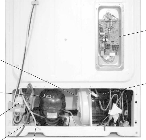
Main
Control
Board
Condenser
Fan
Jelly Roll
Condenser
Compressor
Water
Solenoids
GEA00917
Capacitor |
Overload |
|
and Relay |
|
(under cover) |
– 14 –

Mechanical Disassembly
Table of Contents
Door Gasket . . . . . . . . . . . . . . . . . . . . . . . . . . . . . . . . . . . . . . . . . . . . . . . . . . . . . . 17
Door Handles . . . . . . . . . . . . . . . . . . . . . . . . . . . . . . . . . . . . . . . . . . . . . . . . . . . . . 17
Doors and Door Hinges . . . . . . . . . . . . . . . . . . . . . . . . . . . . . . . . . . . . . . . . . . . . 17
Door Removal . . . . . . . . . . . . . . . . . . . . . . . . . . . . . . . . . . . . . . . . . . . . . . . . . . . . 17
Fresh Food Door Adjustment . . . . . . . . . . . . . . . . . . . . . . . . . . . . . . . . . . . . . . . 18
Control Panel . . . . . . . . . . . . . . . . . . . . . . . . . . . . . . . . . . . . . . . . . . . . . . . . . . . . . 18
Fresh Food Light . . . . . . . . . . . . . . . . . . . . . . . . . . . . . . . . . . . . . . . . . . . . . . . . . . 19
Freezer Door Light Switch . . . . . . . . . . . . . . . . . . . . . . . . . . . . . . . . . . . . . . . . . . 19
Water Filter Cartridge . . . . . . . . . . . . . . . . . . . . . . . . . . . . . . . . . . . . . . . . . . . . . . 19
Shelves . . . . . . . . . . . . . . . . . . . . . . . . . . . . . . . . . . . . . . . . . . . . . . . . . . . . . . . . . . 20
Drawers and Bins . . . . . . . . . . . . . . . . . . . . . . . . . . . . . . . . . . . . . . . . . . . . . . . . . 20
Door Shelf Extenders . . . . . . . . . . . . . . . . . . . . . . . . . . . . . . . . . . . . . . . . . . . . . . 21
Freezer Light . . . . . . . . . . . . . . . . . . . . . . . . . . . . . . . . . . . . . . . . . . . . . . . . . . . . . 21
Icemaker . . . . . . . . . . . . . . . . . . . . . . . . . . . . . . . . . . . . . . . . . . . . . . . . . . . . . . . . . 21
Ice Dispenser Drive . . . . . . . . . . . . . . . . . . . . . . . . . . . . . . . . . . . . . . . . . . . . . . . . 22
Evaporator Fan . . . . . . . . . . . . . . . . . . . . . . . . . . . . . . . . . . . . . . . . . . . . . . . . . . . 22
Defrost Heater and Freezer Thermistor . . . . . . . . . . . . . . . . . . . . . . . . . . . . . . . 23
Overtemperature Thermostat and Evaporator Thermistor . . . . . . . . . . . . . . . . 24
– 15 –
Fresh Food Thermistor . . . . . . . . . . . . . . . . . . . . . . . . . . . . . . . . . . . . . . . . . . . . . 24
Door Dispenser Control Panel . . . . . . . . . . . . . . . . . . . . . . . . . . . . . . . . . . . . . . . 24
Door Dispenser Target Switch . . . . . . . . . . . . . . . . . . . . . . . . . . . . . . . . . . . . . . . 24
Ice Crusher . . . . . . . . . . . . . . . . . . . . . . . . . . . . . . . . . . . . . . . . . . . . . . . . . . . . . . 25
Ice Dispenser Drive Motor . . . . . . . . . . . . . . . . . . . . . . . . . . . . . . . . . . . . . . . . . . 25
Ice Cube Solenoid . . . . . . . . . . . . . . . . . . . . . . . . . . . . . . . . . . . . . . . . . . . . . . . . . 26
Evaporator . . . . . . . . . . . . . . . . . . . . . . . . . . . . . . . . . . . . . . . . . . . . . . . . . . . . . . . 26
Condenser Fan . . . . . . . . . . . . . . . . . . . . . . . . . . . . . . . . . . . . . . . . . . . . . . . . . . . 27
Dispenser Heater . . . . . . . . . . . . . . . . . . . . . . . . . . . . . . . . . . . . . . . . . . . . . . . . . . 27
Main Control Board . . . . . . . . . . . . . . . . . . . . . . . . . . . . . . . . . . . . . . . . . . . . . . . . 28
Roller Assembly . . . . . . . . . . . . . . . . . . . . . . . . . . . . . . . . . . . . . . . . . . . . . . . . . . 28
Water Solenoid . . . . . . . . . . . . . . . . . . . . . . . . . . . . . . . . . . . . . . . . . . . . . . . . . . . 28
Fresh Food Air Damper . . . . . . . . . . . . . . . . . . . . . . . . . . . . . . . . . . . . . . . . . . . . 29
– 16 –

Door Gasket
The rear flange of the gasket is positioned between the inner and outer door panels. The screws under the gasket flap must be loosened.
1.Remove the door bins.
2.Loosen 40 screws located under the door gasket.
3.Remove the gasket from the interior of the door liner.
Note: The back side of the door liner has doublesided tape at the corners.
Screws
GEA00866
Door Handles
Door handles are front mounted and secured with Torx-style screws.
1.Remove the handle trim covers by inserting a thin flat-blade screwdriver about 2 in. from the end of top cover trim. Pry up enough to insert your fingers and lift to free trim from 2 plastic locking tabs inserted in rectangle door holes. Reverse to reinstall, taking care to align cover trim correctly. The top and bottom are not interchangeable.
2.Remove 2 T-20 Torx screws from the upper and lower ends of the handle.
3.Remove the handle.
Doors and Door Hinges
IMPORTANT: The freezer door is not adjustable. The fresh food door can be adjusted up and down to match the height of the freezer door. Adjust the fresh food door up or down using the hinge adjustment pin (located on the fresh food lower door hinge).
The fresh food and freezer lower door hinges are equipped with replaceable cam risers. Cam risers assist in door closure.
When the fresh food door is adjusted too high, the cam riser will not be engaged. If the cam riser is not engaged, the door will not close properly. Refer to the Fresh Food Door Adjustment section in this chapter for more information.
IMPORTANT: The refrigerator rollers must be adjusted correctly to ensure proper door closure. Refer to the Roller Assembly section in this chapter for more information.
Door Removal
1.Remove the upper hinge cover by removing the Phillips screw.
2.With the door in the closed position, disconnect the wiring harness (freezer side only).
– 17 –

3.Remove the base grille.
4.Disconnect the water supply tube. To disconnect the tube, push in the white collar on the quick connector and pull the tube out.
GEA00869
5.Remove the water tube protection (black collar).
6.Remove 2 upper hinge screws.
7.Lift the upper hinge and move it to the side (the gasket is located under the hinge).
CAUTION: Do not side-load hinges.
NOTE: Freezer door only - Guide the water line through hinge while lifting the door from hinge.
8.Open the door 90 degrees and lift the door straight up and off the lower hinge.
Cam with 
Thimble
Screw
Cam Riser
Hinge
Adjustment
Pin
Hinge |
GEA00909 |
9.Remove the screw, hinge cam, and thimble from the bottom of the door.
10.Fresh Food Door Only: Remove the hinge adjustment pin and cam riser from the lower hinge.
11.Freezer Door Only: Remove the cam riser and washer from the lower hinge.
12.Remove 2 screws and lower hinge from cabinet.
Fresh Food Door Adjustment
IMPORTANT: The refrigerator rollers must be adjusted correctly to ensure proper door closure. Refer to the Roller Assembly section in this chapter for more information.
The freezer door is not adjustable. The fresh food door can be adjusted to match the height of the freezer door.
1.Remove the base grille (opening the door makes grille removal easier).
2.Turn the hinge adjustment pin (located on the fresh food lower hinge) clockwise to raise the door and counterclockwise to lower the door.
Control Panel
The control panel, located at the front of the fresh food compartment, contains temperature control encoders for fresh food and freezer sections and the fresh food door light switch.
1.Remove 2 screws located in the bottom of the control panel. Slide the panel down.
– 18 –
2.Disconnect the connectors for the door light switch and temperature control switches.
Connectors
Encoder
Board
GEA00870 |
Freezer Door Light Switch |
3.Disconnect the connectors for the light and temperature control encoders.
4.Disconnect the temperature control encoder connector.
5.Remove the mounting nuts for both encoders.
Note: Both switches must be replaced because they are mounted on a common circuit board.
Mounting
Nuts
The freezer door light switch is located on the left of the freezer compartment.
1.Slide a small flat-blade screwdriver under the switch and push the locking tab. Pull out the switch.
2.Disconnect the harness connector and remove the switch.
GEA00871
6.Disconnect the refrigerator door light switch supply connector.
7.Push the locking tab in and slide the switch out of the panel.
Fresh Food Light
The lower fresh food light is located under an opaque cover in the lower portion of the fresh food compartment in some models.
Note: The upper light cover removal is covered in the previous procedure.
1.Remove the lower light cover by lifting it off the dowels.
2.Remove 2 40-watt appliance light bulbs.
Water Filter Cartridge
Note: The water filter should be replaced every 6 months. Warranty life is 30 days.
The water filter cartridge is located in the upper right corner of the fresh food compartment. When the LED illuminates, change the water filter. On those models without the LED, change the filter when the water flow decreases to the dispenser or icemaker.
1.Remove the old cartridge by slowly turning it to the left. Do not pull the cartridge down. A small amount of water may drip when the cartridge is removed.
– 19 –
 Loading...