


CP15F10A


 /
/

Table of Contents |
|
Air Conditioner Safety |
1 |
Installation Requirements |
3 |
Tools and Parts .................................................................................................................................................................... |
3 |
Location Requirements |
3 |
Electrical Requirements |
4 |
Installation Instructions .................................................................................................................................................. |
6 |
Unpacking |
6 |
Window Installation (on some models) |
7 |
Through-the-Wall Cabinet Installation ............................................................................................................................... |
9 |
Complete Installation |
10 |
Air Conditioner Use |
11 |
Starting Your Air Conditioner—Digital Control .............................................................................................................. |
12 |
Remote Control Operation |
13 |
Normal Sounds |
13 |
Air Conditioner Care........................................................................................................................................................ |
14 |
Cleaning the Air Filter |
14 |
Cleaning the Front Panel |
14 |
Repairing Paint Damage ................................................................................................................................................... |
14 |
Annual Maintenance |
14 |
Troubleshooting |
14 |
Assistance or Service ...................................................................................................................................................... |
15 |
Warranty |
16 |
1
General Instructions
This Installation and Operation Manual has been designed to insure maximum satisfaction in the performance of your unit. For years of trouble-free service, please follow the installation instructions closely. We cannot overemphasize the importance of proper installation. We have added new information to the basic instructions to help you achieve success.
 WARNING
Refrigeration system under high pressure.
Do not puncture, heat, expose to flame or incinerate.
Only certified refrigeration technicians should service this equipment.
R410A systems operate at higher pressures than R22 equipment. Appropriate safe service and handling practices must be used.
Only use gauge sets designed for use with R410A. Do not use standard R22 gauge sets.
 WARNING
Please read this manual thoroughly prior to equipment installation or operation.
It is the installer’s responsibility to properly apply and install the equipment. Installation must be in conformance with the NFPA 70-2008 National Electric Code or current edition, International Mechanic Code 2009 or current edition and any other applicable local or national codes.
Failure to do so can result in property damage, personal injury and / or death.
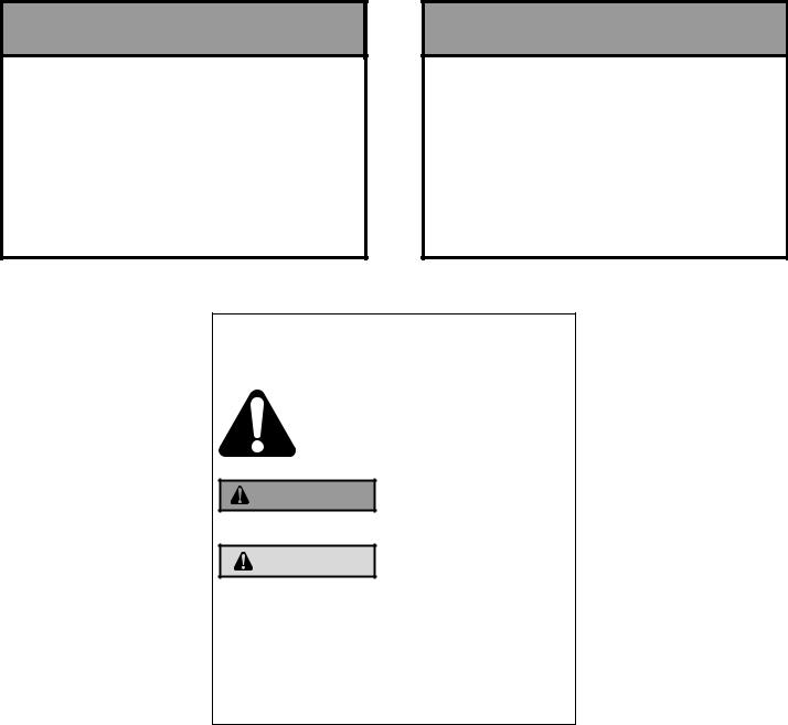
Your safety and the safety of others are very important.
We have provided many important safety messages in this manual and on your appliance. Always read and obey all safety messages.
This is a safety Alert symbol. This symbol alerts you to potential hazards that can kill or hurt you and others.
All safety messages will follow the safety alert symbol with the word “WARNING” or “CAUTION”. These words mean:
Indicates a hazard which, if not WARNING avoided, can result in severe personal injury or death and damage
to product or other property.
CAUTION Indicates a hazard which, if not avoided, can result in personal injury
and damage to product or other property.
All safety messages will tell you what the potential hazard is, tell you how to reduce the chance of injury, and tell you what will happen if the instructions are not followed.
NOTICE |
occur if |
instructions are |
not |
|
Indicates |
property damage |
can |
|
|
|
|
followed. |
|
|
|
2

K
K. pan-headPhillipsscrews(2)
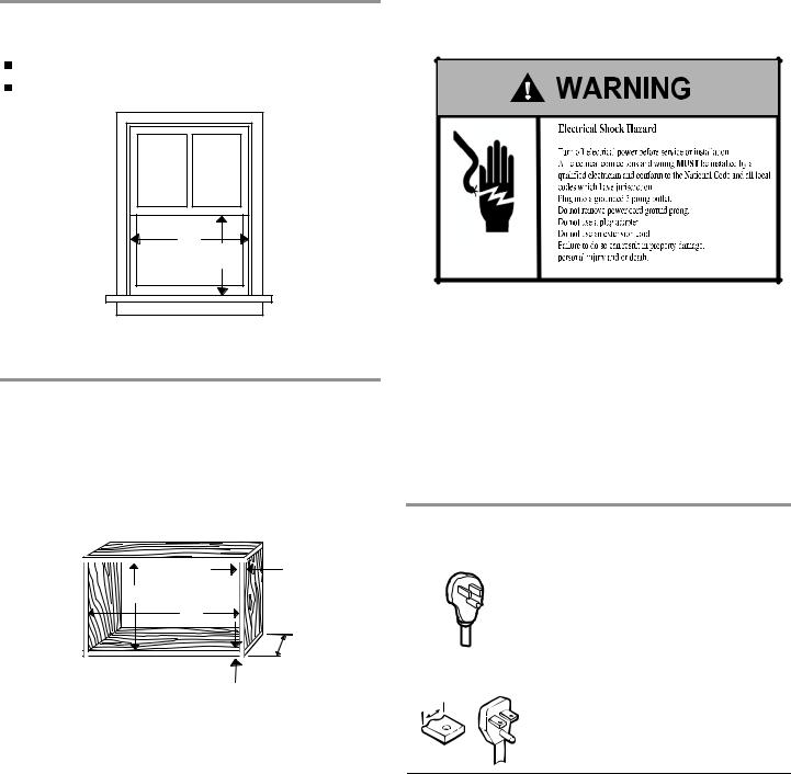
Window installation |
Electrical Requirements |
|
Window opening measurements:
27"min. to 42" max. (76.2 cm to 101.6 cm) opening width (A).
20" min. (50.8 cm) opening height (B).
|
A |
|
|
|
B |
A .27" |
min. (76 |
. 2 c m) |
B . 20" min. (50 |
. 8 c m) |
|
Through-the-wall installation
The wall opening measurements should be:
Height (A): 17 ¼" plus twice thickness of wood used to build frame
Width (B): 26 ¼"
Depth (D): 4" minimum to 8" maximum.
C |
A |
B |
D |
|
C |
A. 17 ¼" |
C. Wood thickness |
B. 26 ¼" |
D. 4" minimum to |
|
8" maximum. |
Ground wire must be connected to ground screw located in lower right corner of air conditioner when air conditioner is in cabinet.
The electrical ratings for your air conditioner are listed on the model and serial number (nameplate) label. The model and serial number label is located behind the front panel on the flange below the control panel area.
Specific electrical requirements are listed in the chart below. Follow the requirements for the type of plug on the power supply cord.
Power supply |
|
|
cord |
Wiring requirements |
|
|
|
|
CP15 |
■ 115-volt (103.5 min. - 126.5 max.) |
|
|
■ |
0-12 amps |
|
■ 15-amp time-delay fuse or circuit breaker |
|
|
■ Use on single outlet circuit only. |
|
|
|
|
CP18 / CP24 |
■ 230-volt (207 min. - 253 max.) |
|
¹⁄" |
|
0-12 amps |
(0.6 cm) |
■ |
|
■ 15-amp time-delay fuse or circuit breaker
■ Use on single outlet circuit only.
4
 Loading...