


Operator’s Manual
®
4-Cycle
WEEDWACKER GAS TRIMMER
Model No. 316.791910
with
• SAFETY
• ASSEMBLY
• OPERATION
• MAINTENANCE
• PARTS LIST
• ESPAÑOL, P. E1
CAUTION: Before using this product, read this manual and follow all safety rules and operating instructions.
Sears, Roebuck and Co., Hoffman Estates, IL 60179, U.S.A.
Visit our website: www.sears.com/craftsman
769-03535A

RULES FOR SAFE OPERATION
TABLE OF CONTENTS
Rules for Safe Operation . . . . . . . . . . . . . . . . . . . . . . . . . . . . . . . .2 Warranty Information . . . . . . . . . . . . . . . . . . . . . . . . . . . . . . . . . . .4 Know Your Unit . . . . . . . . . . . . . . . . . . . . . . . . . . . . . . . . . . . . . . . .4 Assembly Instructions . . . . . . . . . . . . . . . . . . . . . . . . . . . . . . . . . . .5 Oil and Fuel Information . . . . . . . . . . . . . . . . . . . . . . . . . . . . . . . . .6 Starting/Stopping Instructions . . . . . . . . . . . . . . . . . . . . . . . . . . . .7 Operating Instructions . . . . . . . . . . . . . . . . . . . . . . . . . . . . . . . . . .8 Maintenance and Repair Instructions . . . . . . . . . . . . . . . . . . . . . . .9 Cleaning and Storage . . . . . . . . . . . . . . . . . . . . . . . . . . . . . . . . . .13 Troubleshooting Chart . . . . . . . . . . . . . . . . . . . . . . . . . . . . . . . . .14 Specifications . . . . . . . . . . . . . . . . . . . . . . . . . . . . . . . . . . . . . . . .15 California Emission Control Warranty Statement . . . . . . . . . . . . .15 Parts List . . . . . . . . . . . . . . . . . . . . . . . . . . . . . . . . . . . . . . . . . . .E19 Service Information . . . . . . . . . . . . . . . . . . . . . . . . . . . .Back Cover
SPARK ARRESTOR NOTE
NOTE: For users on U.S. Forest Land and in the states of California, Maine, Oregon and Washington. All U.S. Forest Land and the state of California (Public Resources Codes 4442 and 4443), Oregon and Washington require, by law that certain internal combustion engines operated on forest brush and/or grass-covered areas be equipped with a spark arrestor, maintained in effective working order, or the engine be constructed, equipped and maintained for the prevention of fire. Check with your state or local authorities for regulations pertaining to these requirements. Failure to follow these requirements could subject you to liability or a fine. This unit is factory equipped with a spark arrestor. If it requires replacement, ask your LOCAL SERVICE DEALER to install the
Accessory Part #753-05297 Spark Arrestor Kit.
The purpose of safety symbols is to attract your attention to possible dangers. The safety symbols, and their explanations, deserve your careful attention and understanding. The safety warnings do not by themselves eliminate any danger. The instructions or warnings they give are not substitutes for proper accident prevention measures.
SYMBOL MEANING
SAFETY ALERT: Indicates danger, warning or caution. Attention is required in order to avoid serious personal injury. May be used in conjunction with other symbols or pictographs.
DANGER: Failure to obey a safety warning will result in serious injury to yourself or to others. Always follow the safety precautions to reduce the risk of fire, electric shock and personal injury.
WARNING: Failure to obey a safety warning can result in injury to yourself and others. Always follow the safety precautions to reduce the risk of fire, electric shock and personal injury.
CAUTION: Failure to obey a safety warning may result in property damage or personal injury to yourself or to others. Always follow the safety precautions to reduce the risk of fire, electric shock and personal injury.
CALIFORNIA PROPOSITION 65 WARNING
WARNING
THE ENGINE EXHAUST FROM THIS PRODUCT CONTAINS CHEMICALS KNOWN TO THE STATE OF CALIFORNIA TO CAUSE CANCER, BIRTH DEFECTS OR OTHER REPRODUCTIVE HARM.
NOTE: Advises you of information or instructions vital to the operation or maintenance of the equipment.
Read the Operator’s Manual and follow all warnings and safety instructions. Failure to do so can result in serious injury to the operator and/or bystanders.
FOR QUESTIONS, CALL 1–800–659-5917
• IMPORTANT SAFETY INSTRUCTIONS •
READ ALL INSTRUCTIONS BEFORE OPERATING
WARNING: When using the unit, you must follow the safety rules. Please read these instructions before operating the unit in order to ensure the safety of the operator and any bystanders. Please keep these instructions for later use.
•Read the instructions carefully. Be familiar with the controls and proper use of the unit.
•Do not operate this unit when tired, ill, or under the influence of alcohol, drugs, or medication.
•Children and teens under the age of 15 must not use the unit, except for teens guided by an adult.
•All guards and safety attachments must be installed properly before operating the unit.
•Inspect the unit before use. Replace damaged parts. Check for fuel leaks. Make sure all fasteners are in place and secure. Replace parts that are cracked, chipped, or damaged in any way. Do not operate the unit with loose or damaged parts.
•Carefully inspect the area before starting the unit. Remove all debris and hard or sharp objects such as glass, wire, etc.
•Be aware of the risk of injury to the head, hands and feet.
•Clear the area of children, bystanders, and pets. At a minimum, keep all children, bystanders, and pets outside a 50 feet (15 m.) radius; there still may be a risk to bystanders from thrown objects. Bystanders should be encouraged to wear eye protection. If you are approached, stop the unit immediately.
•Use only Craftsman XTRA QUIET™ 0.095 inch (2.413 mm) diameter original equipment manufacturer replacement line. Never use metal-reinforced line, wire or rope. These can break
off and become dangerous projectiles.
•Squeeze the throttle control and check that it returns automatically to the idle position. Make all adjustments or repairs before using unit.
SAFETY WARNINGS FOR GAS UNITS
WARNING: Gasoline is highly flammable, and its vapors can explode if ignited. Take the following precautions:
•Store fuel only in containers specifically designed and approved for the storage of such materials.
•Always stop the engine and allow it to cool before filling the fuel tank. Never remove the fuel tank cap or add fuel when the engine is hot. Never operate the unit without the fuel cap securely in place. Loosen the fuel tank cap slowly to relieve any pressure in the tank.
•Add fuel in a clean, well-ventilated outdoor area where there are no sparks or flames. Remove the fuel cap slowly, and only after the engine stops. Do not smoke while fueling. Wipe up any spilled fuel from the unit immediately.
•Avoid creating a source of ignition for spilled fuel. Do not start the engine until fuel vapors dissipate.
•Move the unit at least 30 feet (9.1 m) from the fueling source and site before starting the engine. Do not smoke. Keep sparks and open flames away from the area while adding fuel or operating the unit.
WHILE OPERATING
•Never start or run the unit inside a closed room or building. Breathing exhaust fumes can be fatal. Operate this unit only in a well-ventilated outdoor area.
•Wear safety glasses or goggles that meet ANSI Z87.1–1989 standards and are marked as such. Wear ear/hearing protection when operating
2

RULES FOR SAFE OPERATION
this unit. Wear a face or dust mask if the operation is dusty.
•Wear heavy long pants, boots, gloves and a long sleeve shirt. Do not wear loose clothing, jewelry, short pants, sandals or go barefoot. Secure hair above shoulder level.
•The cutting attachment shield must always be in place while operating the unit as a trimmer. Do not operate unit without both trimming lines extended, and the proper line installed. Do not extend the trimming line beyond the length of the shield.
•This unit has a clutch. The cutting attachment remains stationary when the engine is idling. If it does not, have the unit adjusted by an authorized service technician.
•Adjust the handle to your size in order to provide the best grip.
•Be sure the cutting attachment is not in contact with anything before starting the unit.
•Use the unit only in daylight or good artificial light.
•Avoid accidental starting. Be in the starting position whenever pulling the starter rope. The operator and unit must be in a stable position while starting. Refer to Starting/Stopping Instructions.
•Use the right tool. Only use this tool for its intended purpose.
•Do not overreach. Always keep proper footing and balance.
•Always hold the unit with both hands when operating. Keep a firm grip on both handles or grips.
•Keep hands, face, and feet at a distance from all moving parts. Do not touch or try to stop the cutting attachment when it rotates.
•Do not touch the engine, gear housing or muffler. These parts get extremely hot from operation, even after the unit is turned off.
•Do not operate the engine faster than the speed needed to cut, trim or edge. Do not run the engine at high speed when not cutting.
•Always stop the engine when cutting is delayed or when walking from one cutting location to another.
•If you strike or become entangled with a foreign object, stop the engine immediately and check for damage. Do not operate before repairing damage. Do not operate the unit with loose or damaged parts.
•Stop the unit, switch the engine to off, and disconnect the spark plug for maintenance or repair.
•Use only replacement parts or accessories recommended for this tool that are distributed by Sears or a Craftsman outlet. Use of any replacement parts or accessories purchased elsewhere may be hazardous, and will also void your warranty.
•Keep unit clean of vegetation and other materials. They may become lodged between the cutting attachment and shield.
•To reduce fire hazard, replace a faulty muffler and spark arrestor. Keep the engine and muffler free from grass, leaves, excessive grease or carbon build up.
OTHER SAFETY WARNINGS
•Never store the unit with fuel in the tank, inside a building where fumes may reach an open flame (pilot lights, etc.) or sparks (switches, electrical motors, etc.).
•Allow the engine to cool before storing or transporting. Be sure to secure the unit while transporting.
•Store the unit in a dry area, locked up or up high to prevent unauthorized use or damage, out of the reach of children.
•Never douse or squirt the unit with water or any other liquid. Keep handles dry, clean and free from debris. Clean after each use, see Cleaning and Storage instructions.
•Keep these instructions. Refer to them often and use them to instruct other users. If you loan someone this unit, also loan them these instructions.
SAVE THESE INSTRUCTIONS
• SAFETY AND INTERNATIONAL SYMBOLS •
This operator's manual describes safety and international symbols and pictographs that may appear on this product. Read the operator's manual for complete safety, assembly, operating and maintenance and repair information.
SYMBOL MEANING |
|
SYMBOL MEANING |
|||||||||||
|
|
|
|
|
|
|
|
|
|
|
|
|
|
|
|
|
|
|
|
• SAFETY ALERT SYMBOL |
|
|
|
|
|
|
• ON/OFF STOP CONTROL |
|
|
|
|
|
|
|
|
|
|
|
|
||
|
|
|
|
|
|
Indicates danger, warning or caution. May be used in |
|
|
|
|
|
|
ON / START / RUN |
|
|
|
|
|
|
conjunction with other symbols or pictographs. |
|
|
|
|
|
|
|
|
|
|
|
|
|
|
|
|
|
|
|
|
|
|
|
|
|
|
|
|
|
|
|
|
|
|
|
|
|
|
|
|
|
|
|
|
|
|
|
|
• ON/OFF STOP CONTROL |
|
|
|
|
|
|
|
|||||||
|
|
|
|
|
|
• READ OPERATOR'S MANUAL |
|
|
|
|
|
|
OFF or STOP |
|
|
|
|
|
|
WARNING: Read the operator’s manual(s) and |
|
|
|
|
|
|
|
|
|
|
|
|
|
|
|
|
|
|
|
|
|
|
|
|
|
|
|
follow all warnings and safety instructions. Failure to |
|
|
|
|
|
|
• HOT SURFACE |
|
|
|
|
|
|
do so can result in serious injury to the operator |
|
|
|
|
|
|
WARNING: Do not touch a hot muffler, gear |
|
|
|
|
|
|
||||||||
|
|
|
|
|
|
and/or bystanders. |
|
|
|
|
|
|
housing or cylinder. You may get burned. These |
|
|
|
|
|
|
|
|
|
|
|
|
|
parts get extremely hot from operation. They remain |
|
|
|
|
|
|
|
|||||||
|
|
|
|
|
|
• WEAR EYE AND HEARING PROTECTION |
|
|
|
|
|
|
hot for a short time after the unit is turned off. |
|
|
|
|
|
|
WARNING: Thrown objects and loud noise can |
|
|
|
|
|
|
|
|
|
|
|
|
|
|
|
|
|
|
|
• THROWN OBJECTS AND ROTATING CUTTER |
|
|
|
|
|
|
|
cause severe eye injury and hearing loss. Wear eye |
|
|
|
|
|
|
|
|
|
|
|
|
|
|
|
|
|
|
|
CAN CAUSE SEVERE INJURY |
|
|
|
|
|
|
|
protection meeting ANSI Z87.1–1989 standards and |
|
|
|
|
|
|
|
|
|
|
|
|
|
|
|
|
|
|
|
WARNING: Do not operate without the cutting |
|
|
|
|
|
|
|
ear protection when operating this unit. Use a full |
|
|
|
|
|
|
|
|
|
|
|
|
|
face shield when needed. |
|
|
|
|
|
|
attachment shield in place. Keep away from the |
|
|
|
|
|
|
|
|
|
|
|
|
|
rotating cutting attachment. |
|
|
|
|
|
|
|
|
|
|
|
|
|
|
|
|
|
|
|
|
• UNLEADED FUEL |
|
|
|
|
|
|
|
|
|
|
|
|
|
|
|
|
|
|
|
|
|
|
|
|
|
|
|
Always use clean, fresh unleaded fuel. |
|
|
|
|
|
|
• CHOKE CONTROL |
|
|
|
|
|
|
|
|
|
|
|
|
|
1. • FULL choke position |
|
|
|
|
|
|
|
|
|
|
|
|
|
2. • PARTIAL choke position |
|
|
|
|
|
|
|
|
|
|
|
|
|
|
|
|
|
|
|
|
• OIL |
|
|
|
|
|
|
3. • RUN choke position |
|
|
|
|
|
|
|
|
|
|
|
|
|
|
|
|
|
|
|
|
Refer to operator’s manual for the proper type of oil. |
|
|
|
|
|
|
|
|
|
|
|
|
|
|
|
|
|
|
|
|
|
|
|
|
|
|
|
|
|
|
|
|
|
|
• SHARP BLADE |
|
|
|
|
|
|
|
|
|
|
|
|
|
WARNING: Sharp blade on cutting attachment |
|
|
|
|
|
|
|
|
|
|
|
|
|
|
|
|
|
|
|
|
• KEEP BYSTANDERS AWAY |
|
|
|
|
|
|
shield. To prevent serious injury, do not touch the |
|
|
|
|
|
|
WARNING: Keep all bystanders, especially |
|
|
|
|
|
|
line cutting blade. |
|
|
|
|
|
|
children and pets, at least 50 feet (15 m) from the |
|
|
|
|
|
|
|
|
|
|
|
|
|
operating area. |
|
|
|
|
|
|
|
|
|
|
|
|
|
|
|
|
|
|
|
|
|
3
WARRANTY STATEMENT
CRAFTSMAN FULL WARRANTY
If this Craftsman product fails due to a defect in material or workmanship within two years from the date of purchase, return it to any Sears store, Parts and Repair Service Center, or other Craftsman outlet in the United States for free repair (or replacement if repair proves impossible).
This warranty applies for only 90 days if this product is ever used for commercial or rental purposes.
This warranty covers ONLY defects in materal and workmanship. Sears will NOT pay for:
•Expendable items that can wear out from normal use within the warranty period, such as cutting line, filters or spark plugs.
•Repairs necessary because of accident or failure to operate or maintain the product according to all supplied instructions.
•Preventive maintenance, or repairs necessary due to improper fuel mixture, contaminated or stale fuel.
This warranty gives you specific legal rights, and you may also have other rights which vary from state to state.
Repair Protection Agreements
Congratulations on making a smart purchase. Your new Craftsman® product is designed and manufactured for years of dependable operation. But like all products, it may require repair from time to time. That’s when having a Repair Protection Agreement can save you money and aggravation.
Here’s what the Repair Protection Agreement* includes:
Expert service by our 10,000 professional repair specialists
Unlimited service and no charge for parts and labor on all covered repairs
Product replacement up to $1500 if your covered product can’t be fixed
Discount of 10% from regular price of service and related installed parts not covered by the agreement; also, 10% off regular price of preventive maintenance check
Fast help by phone – we call it Rapid Resolution – phone support from a Sears representative. Think of us as a “talking owner’s manual.”
Once you purchase the Repair Protection Agreement, a simple phone call is all that it takes for you to schedule service. You can call anytime day or night, or schedule a service appointment online.
The Repair Protection Agreement is a risk-free purchase. If you cancel for any reason during the product warranty period, we will provide a full refund. Or, a prorated refund any time after the product warranty period expires. Purchase your Repair Protection Agreement today!
Some limitations and exclusions apply. For prices and additional information in the U.S.A. call 1-800-827-6655. *Coverage in Canada varies on some items. For full details call Sears Canada at 1-800-361-6665.
Sears Installation Service
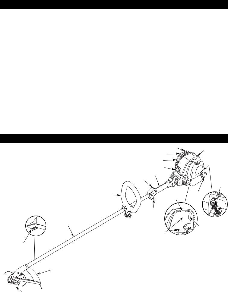
KNOW YOUR UNIT
APPLICATIONS |
Spark Arrestor |
Spark Plug |
As a trimmer: |
Muffler |
|
• Cutting grass and light weeds |
Muffler Guard |
|
• Decorative trimming around trees, fences, etc. |
|
|
Starter Rope Grip |
|
|
|
|
|
|
Shaft Grip |
|
|
On/Off Stop Control |
|
D-Handle |
Choke |
Fuel |
|
Lever |
Cap |
|
|
|
|
Throttle |
|
|
Control |
|
Shaft |
|
|
Housing |
|
|
|
|
Primer |
|
Air Filter Cover |
Bulb |
|
|
|
Line |
|
|
Cutting |
|
|
Blade |
|
|
Oil Fill
Plug/
Dipstick
Cutting Shield
Rapid Rewind™ Head
4

ASSEMBLY INSTRUCTIONS
ADJUSTING THE D-HANDLE
1. Locate the wing nut on the D-Handle. Loosen the wing nut enough to loosen the D-Handle (Fig. 1).
NOTE: Do not remove wing nut, washer, or bolt.
2. |
Rotate the D-Handle to the upright position on the front side |
|
|
of the shaft housing (Fig. 1). |
|
NOTE: The D-handle should slant towards the powerhead of the |
|
|
|
unit. |
|
3. |
Hold the unit in the operating position (Fig. 2). If necessary, |
|
|
reposition the D-handle to the location that provides the best |
|
|
grip. |
|
4. |
Tighten the wing nut until the D-Handle is secure. |
|
|
. 1 |
Fig. 2 |
5
OIL AND FUEL INFORMATION
WARNING: OVERFILLING OIL CRANKCASE MAY CAUSE SERIOUS PERSONAL INJURY. Check and maintain the proper oil level in the crank case; it is important and cannot be overemphasized. Check the oil before each use and change it as needed. See Changing the Oil.
RECOMMENDED OIL TYPE
Using the proper type and weight of oil in the crankcase is extremely important. Check the oil before each use and change the oil regularly. Failure to use the correct oil, or using dirty oil, can cause premature engine wear and failure.
Use a high-quality SAE 30 weight oil of API (American Petroleum Institute) service class SF, SG, SH.
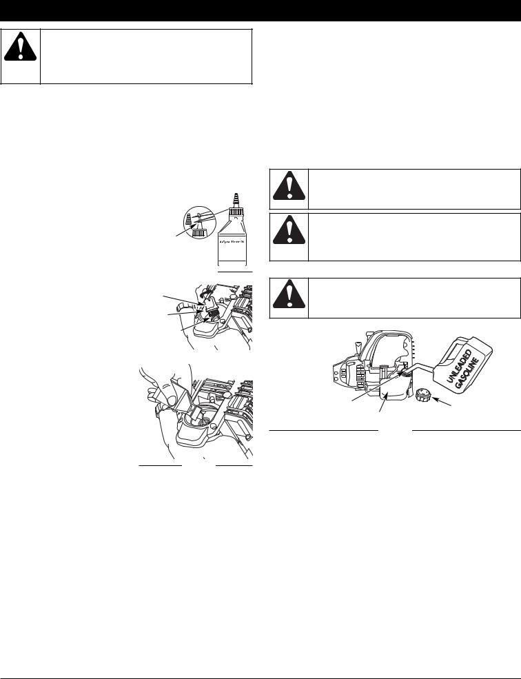
ADDING OIL TO CRANKCASE: INITIAL USE
NOTE: This unit is shipped without oil. In order to avoid damage to the unit, put oil in the crankcase before you attempt to start the unit.
Your unit is supplied with one 3.04 fluid oz. (90 ml.) bottle of SAE 30 SF, SG, SH oil (Fig. 3).
NOTE: Save the empty oil bottle. It |
|
|
|
|
|
|
|
|
|
|
|
|
|
|
|
|
|
|
|
|
|
|
|
|
|
can be used to measure the Funnel |
|
|
|
|
|
|
|
|
|
|
||
correct amount during future |
Spout |
|||||||||||
|
|
|
|
|
|
|
|
|
|
|
|
|
oil changes. See Changing the |
|
|
|
|
|
|
|
|
|
|
|
|
Oil. |
|
Fig. 3 |
||||||||||
|
|
|||||||||||
1.Unscrew the top of the bottle of
oil and remove the paper seal |
Oil Fill Plug |
covering the opening. Replace |
|
the top. Next, cut the tip off the |
O-Ring |
funnel spout (Fig. 3). |
|
2. Tip unit so that the back of the |
Oil Fill Hole |
engine is facing up in a vertical |
|
position. |
|
3. Remove the oil fill plug from the |
Fig. 4 |
|
|
crankcase (Fig. 4). |
|
4. Pour the entire bottle of oil into the oil fill hole (Fig. 5).
NOTE: Never add oil to the fuel or fuel tank.
5. Wipe up any oil that may have spilled and reinstall the oil fill plug.
Check oil before each use and
change as needed. Refer to Fig. 5 Checking the Oil Level.
RECOMMENDED FUEL TYPE
Old fuel is the primary reason for improper unit performance. Be sure to use fresh, clean, unleaded gasoline. Dispose of the old gasoline in accordance to Federal, State and Local regulations.
NOTE: This is a four cycle engine. In order to avoid damage to the unit, do not mix oil with gasoline.
Definition of Blended Fuels
Today's fuels are often a blend of gasoline and oxygenates such as ethanol, methanol or MTBE (ether). Alcohol-blended fuel absorbs water. As little as 1% water in the fuel can form acids when stored. Use fresh fuel (less than 60 days old), when using alcohol-blended
fuel.
Using Blended Fuels
If you choose to use a blended fuel, or its use is unavoidable, follow recommended precautions:
•Always use fresh unleaded gasoline
•Use a gas stabilizer fuel additive
•Drain tank and run the engine dry before storing unit
Using Fuel Additives
The use of a gas stabilizer will inhibit corrosion and minimize the formation of gum deposits. Using a fuel additive can keep fuel from forming harmful deposits in the carburetor for up to six (6) months. Add 0.8 oz. (23 ml.) of fuel additive per gallon of fuel according to the instructions on the fuel additive container. NEVER add fuel additives directly to the unit's gas tank.
WARNING: Add fuel in a clean, well ventilated outdoor area. Wipe up any spilled fuel immediately. Avoid creating a source of ignition for spilt fuel. Do not start the engine until fuel vapors dissipate.
WARNING: Gasoline is extremely flammable. Ignited vapors may explode. Always stop the engine and allow it to cool before filling the fuel tank. Do not smoke while filling the tank. Keep sparks and open flames at a distance from the area.
FUELING THE UNIT
WARNING: Remove fuel cap slowly to avoid injury from fuel spray. Never operate the unit without the fuel cap securely in place.
Gas Can Spout
Fuel Cap
Fuel Tank
Fig. 6
1.Remove the fuel cap (Fig. 6).
2.Place the gas container’s spout into the fill hole on the fuel tank (Fig. 6) and fill the tank.
NOTE: Do not overfill the tank.
3.Wipe up any gasoline that may have spilled.
4.Reinstall the fuel cap.
5.Move the unit at least 30 ft. (9.1 m) from the fueling source and site before starting the engine.
6
STARTING AND STOPPING INSTRUCTIONS
WARNING: Operate this unit only in a well-ventilated outdoor area. Carbon monoxide exhaust fumes can be lethal in a confined area.
WARNING: Avoid accidental starting. Make sure you are in the starting position when pulling the starter rope (Fig. 8). To avoid serious injury, the operator and unit must be in a stable position while starting.
STARTING INSTRUCTIONS
1.Check the oil level in the crankcase. Refer to Checking the Oil Level.
2.Fill the fuel tank with fresh, clean unleaded gasoline. Refer to Fueling the Unit.
NOTE: There is no need to turn the unit on. The On/Off Stop Control is in the ON ( I ) position at all times.

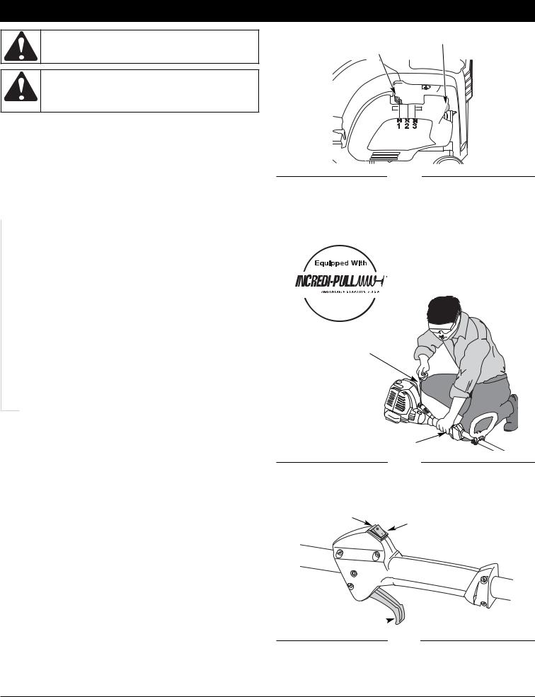
 3. Fully press and release the primer bulb 10 times, slowly. Some amount of fuel should be visible in the primer bulb and fuel lines (Fig. 7). If you can’t see fuel in the bulb, press and release the bulb as many times as it takes before you can see fuel in it.
COLD UNIT START
4.Place the choke lever in Position 1 (Fig. 7).
5.Crouch in the starting position (Fig. 8). While squeezing the throttle control, pull the starter rope out with a slow and steady motion 5 times.
6.Place the choke lever in Position 2 (Fig. 7).
7.While squeezing the throttle control, pull the starter rope out with a slow and steady motion 1 to 4 times to start the engine.
8.Keep the throttle squeezed and allow the engine to warm up for 15 to 30 seconds.
9.Place the choke lever in Position 3 (Fig. 7). The unit is ready for use.
IF... The engine does not start, go back to step 3.
IF... The engine fails to start after a few attempts, place the choke lever in Position 3 and squeeze the throttle control. Pull the starter rope out with a slow and steady motion 3 to 8 times, the engine should start. If not, pull 3 to 8 more times.
WARM UNIT RESTART... If the unit is already hot, place the choke lever in Position 1. While squeezing the throttle control, pull the starter rope to restart. Place the choke lever in Position 3.
NOTE: The unit uses the Incredi-Pull™ starting system with MAX FIRE IGNITION™ , which significantly reduces the effort required to start the engine.
You must pull the starter rope out far enough to hear the engine attempt to start. There is no need to pull the rope briskly-- there is no harsh resistance when pulling. Be aware that this starting method is vastly different from (and much easier than) what you may be used to.
STOPPING INSTRUCTIONS
1.Release your hand from the throttle control. Allow the engine to cool down by idling.
2.Press and hold On/Off Stop Control in the OFF (O) position until engine comes to a complete stop (Fig. 9)
Primer Bulb
Choke Lever
Fig. 7
Trimmer
Incredi-Pull™
Starter Rope
Throttle Control
Fig. 8
Stop/Off (O)
Start/On (I)
Throttle Control 
Fig. 9
7
OPERATING INSTRUCTIONS
WARNING: Always wear eye, hearing, foot and body protection to reduce the risk of injury when operating this unit.
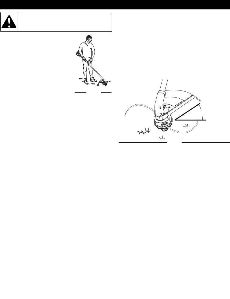
HOLDING THE TRIMMER
Before operating the unit, stand in the operating position (Fig. 10). Check for the following:
• The operator is wearing eye protection and proper clothing
• With a slightly-bent right arm, the operator’s right hand is holding the shaft grip
• The operator’s left arm is straight, the left hand holding the handle
• The unit is at waist level
• The cutting attachment is parallel to the |
|
|
ground and easily contacts the grass |
|
|
without the need to bend over |
Fig. 10 |
|
BUMP KNOB LINE ADVANCE |
||
|
Tap the bump knob on the ground to advance the cutting line when necessary.
TIPS FOR BEST TRIMMING RESULTS
•For best trimming results, operate unit with throttle control fully squeezed.
•Keep the cutting attachment parallel to the ground.
•Do not force the cutting attachment. Allow the tip of the line to do the cutting, especially along walls. Cutting with more than the tip will reduce cutting efficiency and may overload the engine.
•Cut grass over 8 inches (200 mm) by working from top to bottom in small increments to avoid premature line wear or engine drag.
•Cut from right to left.
•Slowly move the trimmer into and out of the cutting area at the desired height. Move either in a forward-backward or side-to- side motion. Cutting shorter lengths produces the best results.
•Trim only when grass and weeds are dry.
•The life of your cutting line is dependent upon:
-Proper adherence of explained trimming techniques
-What vegetation is cut
-Where vegetation is cut
For example, the line will wear faster when trimming against a foundation wall as opposed to trimming around a tree. It is normal for some line breakage to occur from regular use.
DECORATIVE TRIMMING
Decorative trimming is accomplished by removing all vegetation around trees, posts, fences and more.
Rotate the whole unit so that the cutting attachment is at a 30° angle to the ground (Fig. 11).
30°
Fig. 11
8

MAINTENANCE AND REPAIR INSTRUCTIONS
LINE INSTALLATION FOR THE RAPID REWIND™ CUTTING HEAD
WARNING: Never use metal-reinforced line, wire, chain or rope. These can break off and become dangerous
Always use Craftsman XTRA QUIET™ 0.095 inch (2.413 mm) original equipment manufacturer replacement line. Lines other than the specified may make the engine overheat or fail.
There are two methods to replace the Rapid Rewind™ trimming line:
•Wind the inner reel with new line
•Install a pre-wound inner reel
Winding the Inner Reel With New Line
NOTE: It Is unnecessary to remove the bump knob to install a new trimming line.
1.Cut two 7 ft (2.1 m) pieces of 0.095-inch (2.413 mm) trimming line.
NOTE: Always use the correct line length when installing trimming line on the unit. The line may not release properly if the line is too long.
2.Hold the outer spool and turn the inner reel counterclockwise to line up the arrows on the outer spool and inner reel (Fig. 12).
Top View Of The Rapid Rewind™
Outer |
Arrows |
Spool |
|
|
Locking |
Locking |
Hole |
Hole |
|
Inner
Reel Bump
Knob
Fig. 12
3.Detach old line ends from locking holes (Fig. 12) and pull old line out through reel eyelets (Fig. 13).
Trimming Line
Eyelet
Line Loading Hole
Fig. 13
4.Making sure arrows are aligned, insert the end of a piece of trimming line straight into one of the two eyelets in the outer spool. Push it up through the line loading hole in the inner reel (Fig. 13). Do not bend the line when inserting it into the eyelet.
5.Insert the line into the locking hole (Fig. 14). Do not push the line more than a 1/2 inch (12.7 mm) into the line locking hole. The line will form a small loop (Fig. 14) when it is inserted correctly.
6.Pull the line from the outer spool until the line is tight against the inner reel (Fig. 15).
7.Repeat procedures 4-6 with the second piece of line in the other eyelet.
NOTE: Do not wind the inner reel before installing the second
Line Locking Hole
Fig. 14
Fig. 15
piece of line.
8.Hold the outer spool. Wind the inner reel counterclockwise until approximately four (4) inches (102 mm) of line remain (Fig. 16). Avoid contact of bump knob while winding. Ensure bump knob is
Fig. 16
tight on shaft before proceeding, turn bump knob clockwise to tighten.
9. If winding the line becomes difficult or if the line jams, pull the ends
Fig. 17
of the line from the spool (Fig. 17). Continue winding the inner reel counterclockwise until 4 inches of line remains on each side.
9
MAINTENANCE AND REPAIR INSTRUCTIONS
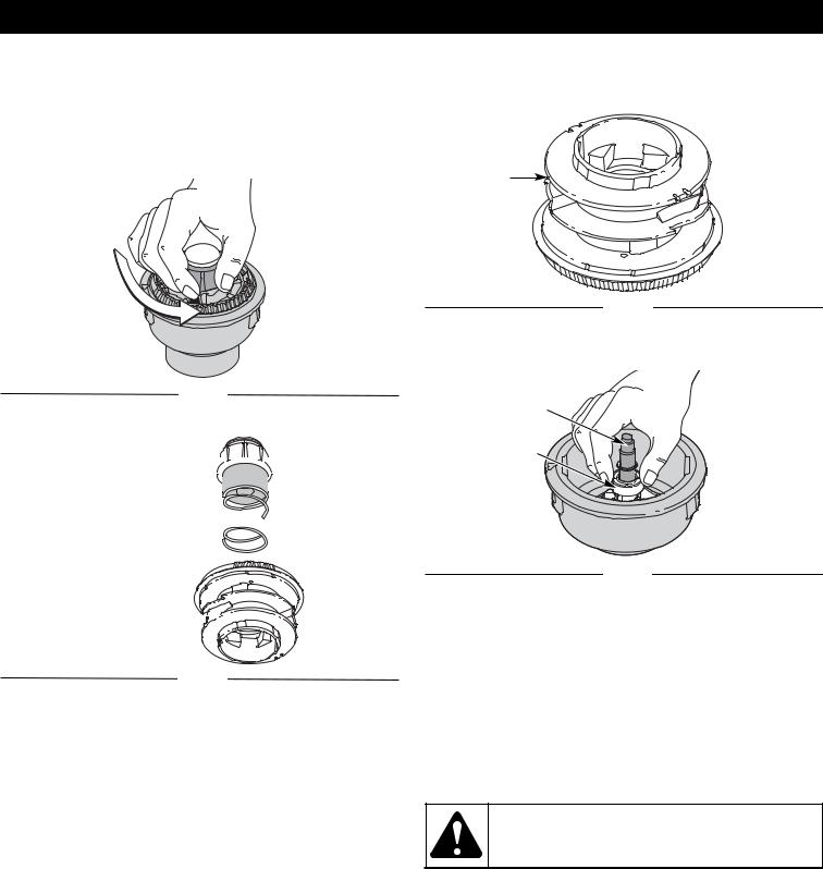
CLEANING THE RAPID REWIND™ HEAD
NOTE: Also perform these steps when replacing inner reel with a new prewound reel.
Cleaning the Rapid Rewind™ may be necessary if:
•A jammed or excessive line must be removed
•The Rapid Rewind™ becomes difficult to wind or does not operate correctly when bumping the head on the ground.
1.Hold the outer spool, and unscrew the bump knob counterclockwise (Fig. 18).
3.Pull the inner reel with existing line from the outer spool.
4.If rewinding with new line, remove any existing line from the inner reel before cleaning. Remove any debris or grass from the knob, spring, inner reel and foam seal. Wash the inner reel with warm soapy water (Fig. 20).
Inner Reel
Fig. 20
5.Clean the shaft and the inner surface of the outer spool. To clean the shaft underneath the plunger, press down on the plunger (Fig. 21). Remove any dirt or debris from the shaft.
Fig. 18
Shaft
2. Pull out the bump knob, spring and foam seal (Fig. 19).
Bump Knob 


Foam Seal 

Spring 

Inner Reel 


Fig. 19
Plunger
Fig. 21
NOTE: The inner reel must be totally dry before reinstalling it into the outer spool. Do not lubricate the inner reel or outer spool assembly.
6.Place the cleaned and empty or new prewound inner reel into the outer spool.
7.Place the bump knob, spring and foam seal onto the inner reel (Fig. 19).
8.Press the bump knob down and tighten clockwise.
9.Install new line in the empty inner reel as described in Line Installation for the Rapid Rewind™.
•MAINTENANCE SCHEDULE •
Perform these required maintenance procedures at the frequency stated in the table. These procedures should also be a part of any seasonal tune-up. NOTE: Some maintenance procedures may require special tools or
skills. If you are unsure about these procedures take your unit to a Sears or other authorized service dealer.
NOTE: Maintenance, replacement, or repair of the emission control devices and system may be performed by a Sears or other authorized service dealer.
In order to assure peak performance of your engine, inspection of the engine exhaust port may be necessary after 50 hours of operation. If you
notice lost RPM, poor performance or general lack of acceleration, this service may be required. If you feel your engine is in need of this inspection, refer service to a Sears or other qualified service dealer for repair. DO NOT attempt to perform this process yourself as engine damage may result from contaminants involved in the cleaning process for the port.
WARNING: To prevent serious injury, never perform maintenance or repairs with unit running. Always service and repair a cool unit. Disconnect the spark plug wire to ensure that the unit cannot start.
FREQUENCY |
MAINTENANCE REQUIRED |
SEE |
|
|
|
|
|
Before starting engine |
Fill fuel tank with fresh fuel |
Page 6 |
|
Check oil |
Page 11 |
||
|
|||
|
|
|
|
Every 10 hours |
Clean and re-oil air filter |
Page 11 |
|
|
|
|
|
First change at 10 hours |
Change oil |
Page 11 |
|
At 25 hours/every 25 hours |
Change oil |
Page 11 |
|
Every 50 hours |
Clean spark arrestor |
Page 13 |
|
|
|
|
|
10 hours on new engine |
Check rocker arm to valve clearance and adjust |
Page 12 |
|
Every 25 hours |
Check rocker arm to valve clearance and adjust |
Page 12 |
|
Every 25 hours |
Check spark plug condition and gap |
Page 13 |
|
As necessary |
Clean the Rapid Rewind™ Head |
Page 10 |
|
|
|
|
10
MAINTENANCE AND REPAIR INSTRUCTIONS
CHECKING THE OIL LEVEL
The importance of checking and maintaining the proper oil level in the crankcase cannot be overemphasized. Check oil before each use:
1.Stop the engine and allow oil to drain into the crankcase.
2.Place the engine on an elevated, level surface with the cutting head shield hanging off the surface to get an accurate oil level
Fig. 22
reading (Fig. 22).
3.Keep dirt, grass clippings and other debris out of the engine. Clean the area around the dipstick before removing it.
4.Remove the oil fill plug.
5.Look into the oil fill hole, use a flashlight if needed. The oil should be just touching the innermost thread (Fig. 23).
6.If the oil level is not touching the innermost thread on the oil fill hole, add a small amount of oil to the oil fill hole and recheck (Fig. 23). Repeat this procedure until the oil level reaches the innermost thread on the oil fill hole.
NOTE: Do not overfill the unit.
NOTE: Make sure the O-ring is in place on the oil fill plug when
Oil Fill Plug
O-Ring 

Oil Fill Hole 
Max Oil Fill Line
Fig. 23 |
|
|
|
Fig. 24 |
|
|
|||
|
|
|
|
|
checking and changing the oil (Fig. 24).
WARNING: Wear gloves to prevent injury when handling unit.
CHANGING THE OIL
For a new engine, change the oil after the first 10 hours of operation. Change the oil while
the engine is still warm. The oil will flow freely and carry away
more impurities.
1. Unplug spark plug boot to prevent accidental starting.
2.Remove the oil fill plug.
3.Pour the oil out of the oil fill hole and into a container by tipping the unit to a vertical
position (Fig. 25). Allow ample time for complete drainage.
4.Wipe up any oil residue on the unit and clean up any oil that may have spilled. Dispose of the oil according to Federal, State and local
regulations. |
Fig. 25 |
5.Refill the crankcase with
3.04 fluid ounce (90 ml) of SAE 30 SF, SG, SH oil.
NOTE: Use the bottle and spout saved from initial use to measure the correct amount of oil. The top of the label on the bottle measures approximately 3.04 ounces (90 ml) (Fig. 26). Check the level; See Checking the Oil Level. If the level is low, add a small amount of oil and recheck. Do not overfill (Fig. 26).
Fill Level
Fig. 26
6.Replace the oil fill plug.
7.Reconnect the spark plug boot.
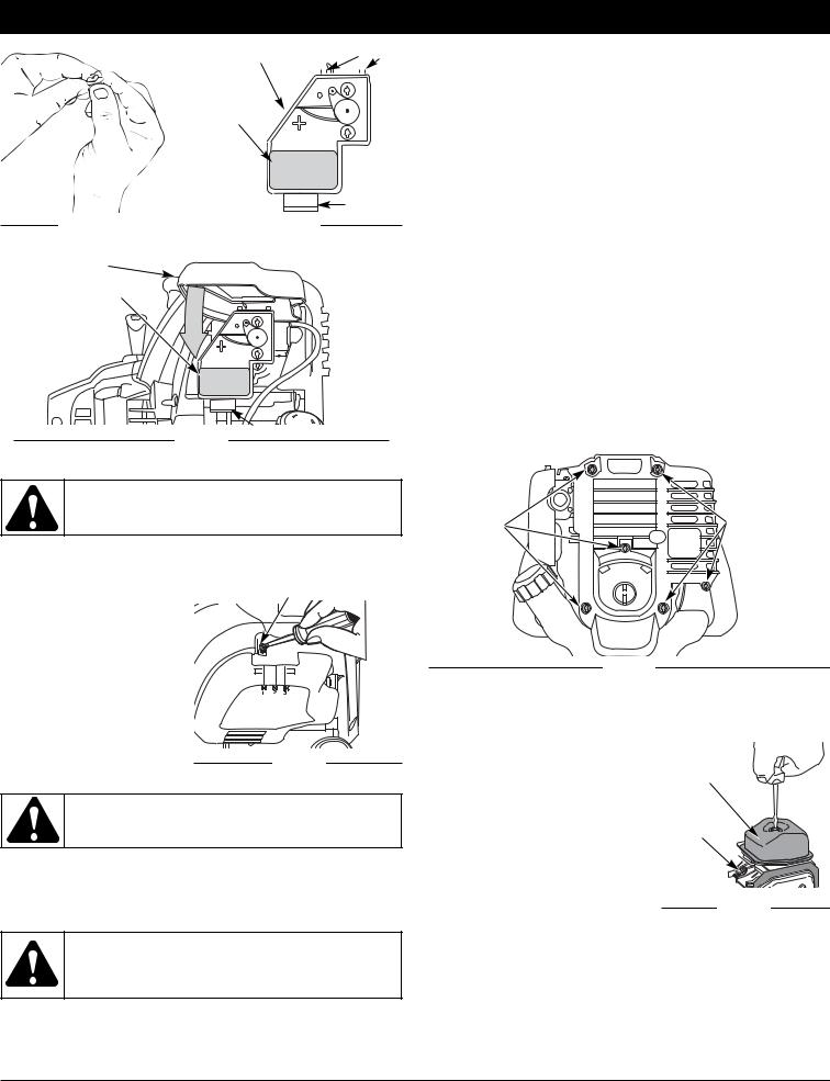
AIR FILTER MAINTENANCE
WARNING: To avoid serious personal injury, always turn the unit off and allow it to cool before you clean or service it.
Cleaning the Air Filter
Clean and re-oil the air filter every 10 hours of operation. It is an important item to maintain. Failure to maintain your air filter properly can result in poor performance or can cause permanent damage to your
Air Filter Cover
Air Filter
Tab
Fig. 27
engine.
1.Open the air filter cover. Push the
tab on the under side of the cover inward. Then pull the air filter cover out and up. (Fig. 27).
2. Remove the air filter (Fig. 30).
3. Wash the filter in detergent and water (Fig. 28). Rinse the filter thoroughly and allow it to dry.
4. Apply enough clean SAE 30 motor oil to lightly coat the filter (Fig. 29).
5.Squeeze the filter to spread and
remove excess oil (Fig. 30).
6. |
Replace the filter (Fig. 27). |
Fig. 28 |
NOTE: If the unit is operated without |
|
|
|
the air filter, you will |
|
|
VOID the warranty. |
|
7. |
Reinstall the air filter cover. |
|
|
Position the slots on the top |
|
|
of the air filter cover onto the |
|
|
tabs at the top of the back |
|
Fig. 29
11
MAINTENANCE AND REPAIR INSTRUCTIONS
Back Plate |
|
|
Tabs |
|
|
|
|
|
|
|
|
|
|
|
Air
Filter
Locking
Tab
Fig. 30 |
|
|
|
Fig. 31 |
|
|
will not idle, adjust the idle speed screw as follows:
1.Start the engine and let it run at a high idle for a minute to warm up. Refer to Starting/Stopping Instructions.
2.Release the throttle trigger and let the engine idle. If the engine stops, insert a small phillips screwdriver in between the Air Filter Cover and the Engine Cover (Fig. 33). Turn the idle speed screw in, clockwise, 1/8 of a turn at a time (as needed) until the engine idles smoothly.
NOTE: The cutting head should not rotate when the engine idles.
3.If the cutting attachment rotates when the engine idles, turn the idle speed screw counterclockwise 1/8 of a turn at a time (as needed), until the head stops turning.
Checking the fuel, cleaning the air filter, and adjusting the idle speed should solve most engine problems. If not and all of the following are true:
Air Filter Cover
Air Filter
Fig. 32 |
Tab |
|
plate (Fig. 31).
WARNING: The cutting head may spin during idle speed adjustments. Wear protective clothing and observe all safety instructions to prevent serious personal injury.
8.Swing the cover down until the tab on the air filter backplate snaps into place in the slot on the air filter cover (Fig. 32).
IDLE SPEED ADJUSTMENT
The idle speed of the engine is adjustable. An idle adjustment screw is between the air filter cover and the engine starter housing (Fig. 33).
NOTE: Careless adjustments can seriously damage your unit. Aside from the idle speed, only a Sears or other qualified service dealer should make carburetor adjustments.
1. Check Fuel
Idle Adjustment Screw
Fig. 33
Old fuel is usually the reason for idle speed problems. Drain and
WARNING: To prevent serious personal injury, make sure the cutting attachment has stopped rotating before you turn it off and set it down.
refill the tank with fresh fuel prior to making any adjustments. Refer to Oil and Fuel Information.
2. Clean Air Filter
The condition of the air filter is important to the operation of the unit. A dirty air filter will restrict air flow. This is often mistaken for
WARNING: The cutting attachment may spin during idle speed adjustments. Wear protective clothing and observe all safety instructions to prevent serious personal injury.
an out of adjustment idle. Check the condition of the air filter before adjusting the idle speed screw. Refer to Air Filter Maintenance.
3. Adjust Idle Speed Screw
If, after checking the fuel and cleaning the air filter, the engine still
•the engine will not idle
•the engine hesitates or stalls on acceleration
•there is a loss of engine power
Have the carburetor serviced by a Sears or other qualified service dealer.
ROCKER ARM CLEARANCE
This requires disassembly of the engine. If you feel unsure or unqualified to perform this, take the unit to a Sears or other qualified service dealer
NOTE: Inspect the valve to rocker arm clearance with a feeler gauge after the first 10 hours of operation and every 25 hours of operation.
• The engine must be cold when checking or adjusting the valve
View Of The Rear Engine Cover
Remove |
Remove |
Screws |
Screws |
Fig. 34
clearance.
• This task should be performed inside, in a clean, dust free area.
1.Remove the six (6) screws on the back of the engine cover with a Flat-head or T-25 Torx screwdriver (Fig. 34).
2.Disconnect the spark plug wire.
3.Clean dirt from around the spark plug. Remove the spark plug from the cylinder head by turning a 5/8 in. socket counterclockwise.
4.Remove the engine cover (Fig. 34).
5.Clean dirt from around the rocker arm cover. Remove the screw holding the rocker arm cover with a large flat blade screwdriver or Torx T-25 bit (Fig. 35). Remove the rocker arm cover and gasket.
Rocker
Arm
Cover
Spark
Plug
Hole
Fig. 35
6.Pull the starter rope slowly to bring the piston to the top of its travel, (known as top dead center). Check that:
•The piston is at the top of its travel. Look in the spark plug hole to view the piston (Fig. 36)
•Both rocker arms move freely, and both valves are closed.
If these statements are not true, repeat step 6.
7.Slide the feeler gauge between the rocker arm and the top of each valve stem. Measure the clearance between the valve stem and rocker arm (Fig. 36 & 37). Measure both the intake and exhaust valves.
12
 Loading...