


OPERATOR’S MANUAL
MANUAL DEL OPERADOR
7-1/4 in., 19.2 Volt Compound Miter Saw
Sierra ingleteadora combinada de 7-1/4 pulg., de 19.2 V
MODEL NO. / NÚMERO DE MODELO 


 315.BT2010


 WARNING: To reduce the risk of injury, the user must read and understand the operator’s manual before using this product.
 ADVERTENCIA: Para reducir el riesgo de lesiones, el usuario debe leer y comprender el manual del operador antes de usar este producto.
Customer Help Line: 1-800-932-3188
Teléfono de atención al consumidor: 1-800-932-3188
Sears Brands Management Corporation,
3333 Beverly Rd., Hoffman Estates, IL 60179 USA
Visit the Craftsman web page: www.sears.com/craftsman Visite el sitio web de Craftsman: www.sears.com/craftsman
BATTERY AND CHARGER SOLD SEPARATELY
BATERÍA Y CARGADOR SE VENDEN POR SEPARADO
Save this manual for future reference
990000668 |
Guarde este manual para futuras consultas |
10-1-13 (REV:03) |
|

TABLE OF CONTENTS / ÍNDICE DE CONTENIDO
ENGLISH |
|
|
|
Warranty...................................................................... |
2 |
|
Introduction................................................................. |
2 |
|
General Safety Rules............................................... |
3-4 |
|
Specific Safety Rules................................................... |
5 |
|
Symbols....................................................................... |
6 |
|
Glossary of Terms........................................................ |
7 |
|
Features................................................................. |
8-10 |
|
Tools Needed............................................................. |
10 |
|
Loose Parts............................................................... |
11 |
|
Assembly............................................................. |
12-17 |
|
Operation............................................................. |
18-25 |
|
Adjustments......................................................... |
26-27 |
|
Maintenance.............................................................. |
28 |
|
Illustrated Parts List............................................. |
30-33 |
Parts Ordering / Service.............................. |
Back Page |
|
ESPAÑOL |
|
|
|
Garantía....................................................................... |
2 |
|
Introducción................................................................. |
2 |
Reglas de seguridad generales............................... |
3-4 |
|
Reglas de seguridad específicas................................. |
5 |
|
|
Símbolos...................................................................... |
6 |
|
Glosario de términos................................................... |
7 |
|
Características....................................................... |
8-10 |
|
Herramientas necesarias........................................... |
10 |
|
Piezas sueltas............................................................ |
11 |
|
Armado................................................................ |
12-17 |
|
Funcionamiento................................................... |
18-25 |
|
Adjustes............................................................... |
26-27 |
|
Mantenimiento........................................................... |
28 |
Pedidos de piezas / Servicio.................. |
Pág. posterior |
|
WARRANTY / GARANTÍA
CRAFTSMAN® ONE YEAR LIMITED WARRANTY
FOR ONE YEAR from the date of purchase, this product is warranted against any defects in material or workmanship. With proof of purchase, defective product will be replaced free of charge.
For warranty coverage details to obtain free replacement, visit the web site: www.craftsman.com
This warranty does not cover the bits, which are expendable parts that can wear out from normal use within the warranty period.
This warranty is void if this product is ever used while providing commercial services or if rented to another person. This warranty gives you specific legal rights, and you may also have other rights which vary from state to state.
Sears Brands Management Corporation, Hoffman Estates, IL 60179
* * *
GARANTÍA LIMITADA DE CRAFTSMAN® POR UN AÑO
Este producto tiene garantía por cualquier defecto en material o mano de obra DURANTE UN AÑO desde la fecha de compra. Los productos defectuosos se remplazarán sin cargo si presenta un comprobante de pago.
Si desea conocer los detalles de la cobertura de la garantía para conseguir reparaciones o recambios, visite el sitio Web: www.craftsman.com
Esta garantía no cubre las brocas, que es una pieza fungible que puede desgastarse por el uso normal durante el período de garantía.
La garantía pierde validez si este producto se utiliza mientras se prestan servicios comerciales o si se alquila a otra persona.
Esta garantía le otorga derechos legales específicos y también puede gozar de otros derechos que varían según el estado.
Sears Brands Management Corporation, Hoffman Estates, IL 60179
INTRODUCTION / INTRODUCCIÓN
This tool has many features for making its use more pleasant and enjoyable. Safety, performance, and dependability have been given top priority in the design of this product making it easy to maintain and operate.
* * *
Esta herramienta ofrece numerosas características para hacer más agradable y placentero su uso. En el diseño de este producto se ha conferido prioridad a la seguridad, el desempeño y la fiabilidad, por lo cual se facilita su manejo y mantenimiento.
2

GENERAL SAFETY RULES
 WARNING: Read and understand all instructions. Failure to follow all instructions listed below, may result in electric shock, fire and/or serious personal injury.
READ ALL INSTRUCTIONS
KNOW YOUR POWER TOOL. Read the operator’s manual carefully. Learn the applications and limitations as well as the specific potential hazards related to this tool.
GUARD AGAINST ELECTRICAL SHOCK BY PREVENTING BODY CONTACT WITH GROUNDED SURFACES. For example: pipes, radiators, ranges, refrigerator enclosures.
KEEP GUARDS IN PLACE and in good working order.
REMOVE ADJUSTING KEYS AND WRENCHES.
Form habit of checking to see that keys and adjusting wrenches are removed from tool before turning it on.
KEEP WORK AREA CLEAN. Cluttered areas and benches invite accidents. DO NOT leave tools or pieces of wood on the tool while it is in operation.
DO NOT USE IN DANGEROUS ENVIRONMENTS.
Do not use power tools in damp or wet locations or expose to rain. Keep the work area well lit.
KEEP CHILDREN AND VISITORS AWAY. All
visitors should wear safety glasses and be kept a safe distance from work area. Do not let visitors contact tool or extension cord while operating.
MAKE WORKSHOP CHILDPROOF with padlocks, master switches, or by removing starter keys.
DON’T FORCE THE TOOL. It will do the job better and safer at the feed rate for which it was designed.
USE THE RIGHT TOOL. Do not force the tool or attachment to do a job for which it was not designed.
DRESS PROPERLY. Do not wear loose clothing, neckties, or jewelry that can get caught and draw you into moving parts. Rubber gloves and nonskid footwear are recommended when working outdoors. Also wear protective hair covering to contain long hair.
ALWAYS WEAR SAFETY GLASSES WITH SIDE SHIELDS. Everyday eyeglasses have only impactresistant lenses, they are NOT safety glasses.
SECURE WORK. Use clamps or a vise to hold work when practical, it is safer than using your hand and frees both hands to operate the tool.
DO NOT OVERREACH. Keep proper footing and balance at all times.
MAINTAIN TOOLS WITH CARE. Keep tools sharp and clean for better and safer performance. Follow instructions for lubricating and changing accessories.
USE RECOMMENDED ACCESSORIES. Consult the operator’s manual for recommended accessories. The use of improper accessories may result in injury.
NEVER STAND ON TOOL. Serious injury could occur if the tool is tipped or if the cutting tool is unintentionally contacted.
CHECK DAMAGED PARTS. Before further use of the tool, a guard or other part that is damaged should be carefully checked to determine that it will operate properly and perform its intended function. Check for alignment of moving parts, binding of moving parts, breakage of parts, mounting and any other conditions
that may affect its operation. A guard or other part that is damaged must be properly repaired or replaced by an authorized service center to avoid risk of personal injury.
USE THE RIGHT DIRECTION OF FEED. Feed work into a blade or cutter against the direction of rotation of the blade or cutter only.
NEVER LEAVE TOOL RUNNING UNATTENDED. TURN THE POWER OFF. Don’t leave tool until it comes to a complete stop.
PROTECT YOUR LUNGS. Wear a face or dust mask if the cutting operation is dusty.
PROTECT YOUR HEARING. Wear hearing protection during extended periods of operation.
KEEP BLADES CLEAN, SHARP, AND WITH SUFFICIENT SET. Sharp blades minimize stalling and kickback.
BLADE COASTS AFTER BEING TURNED OFF.
NEVER USE IN AN EXPLOSIVE ATMOSPHERE.
Normal sparking of the motor could ignite fumes.
KEEP TOOL DRY, CLEAN, AND FREE FROM OIL AND GREASE. Always use a clean cloth when cleaning. Never use brake fluids, gasoline, petroleum-based products, or any solvents to clean tool.
STAY ALERT AND EXERCISE CONTROL. Watch what you are doing and use common sense. Do not operate tool when you are tired. Do not rush.
DO NOT USE TOOL IF SWITCH DOES NOT TURN IT ON AND OFF. Have defective switches replaced by an authorized service center.
USE ONLY CORRECT BLADES. Do not use blades with incorrect size holes. Never use blade washers or blade bolts that are defective or incorrect. The maximum blade capacity of your saw is 7-1/4 in.
BEFORE MAKING A CUT, BE SURE ALL ADJUSTMENTS ARE SECURE.
BE SURE BLADE PATH IS FREE OF NAILS. Inspect for and remove all nails from lumber before cutting.
NEVER TOUCH BLADE or other moving parts during use.
3 — English

GENERAL SAFETY RULES
NEVER START A TOOL WHEN ANY ROTATING COMPONENT IS IN CONTACT WITH THE WORKPIECE.
DO NOT OPERATE A TOOL WHILE UNDER THE INFLUENCE OF DRUGS, ALCOHOL, OR ANY MEDICATION.
WHEN SERVICING use only identical replacement parts. Use of any other parts may create a hazard or cause product damage.
DOUBLE CHECK ALL SETUPS. Make sure blade is tight and not making contact with saw or workpiece before connecting to power supply.
ENSURE THE SWITCH IS IN THE OFF POSITION BEFORE INSERTING BATTERY PACK. Inserting the battery pack into power tools that have the switch on invites accidents.
RECHARGE ONLY WITH THE CHARGER SPECIFIED BY THE MANUFACTURER. A charger that is suitabe for one type of battery pack may create a risk of fire when used with another battery pack.
USE POWER TOOLS ONLY WITH SPECIFICALLY DESIGNATED BATTERY PACKS. Use of any other battery packs may create a risk of injury or fire.
FOR USE WITH 19.2 V NICKEL-CADMIUM AND 19.2 V LITHIUM-ION BATTERY PACKS, see tool/
appliance/battery pack/charger correlation supplement 988000-272.
WHEN BATTERY PACK IS NOT IN USE, KEEP IT AWAY FROM OTHER METAL OBJECTS LIKE PAPER CLIPS, COINS, KEYS, NAILS, SCREWS, OR OTHER SMALL METAL OBJECTS THAT CAN MAKE A CONNECTION FROM ONE TERMINAL TO ANOTHER.
Shorting the battery terminals together may cause burns or a fire.
UNDER ABUSIVE CONDITIONS, LIQUID MAY BE EJECTED FROM THE BATTERY; AVOID CONTACT. IF CONTACT ACCIDENTALLY OCCURS, FLUSH WITH WATER. IF LIQUID CONTACTS EYES, ADDITIONALLY SEEK MEDICAL HELP. Liquid ejected from the battery may cause irritation or burns.
DISCONNECT BATTERY PACK FROM TOOL OR PLACE THE SWITCH IN THE LOCKED OR OFF POSITION BEFORE MAKING ANY ADJUSTMENTS, CHANGING ACCESSORIES, OR STORING THE TOOL. Such preventive safety measures reduce the risk of starting the tool accidentally.
TOOL SERVICE MUST BE PERFORMED ONLY BY QUALIFIED REPAIR PERSONNEL using only identical replacement parts. This will ensure that the safety of the power tool is maintained.
SPECIFIC SAFETY RULES
FIRMLY CLAMP OR BOLT the tool to a workbench or table at approximately hip height.
KEEP HANDS AWAY FROM CUTTING AREA. Do not reach underneath work or in blade cutting path with hands and fingers for any reason. Always turn the power off.
ALWAYS SUPPORT LONG WORKPIECES while cutting to minimize risk of blade pinching and kickback. Saw may slip, walk or slide while cutting long or heavy boards.
ALWAYS USE A CLAMP to secure the workpiece when possible.
BE SURE THE BLADE CLEARS THE WORKPIECE.
Never start the saw with the blade touching the workpiece. Allow motor to come up to full speed before starting cut.
MAKE SURE THE MITER TABLE AND SAW ARM (BEVEL FUNCTION) ARE LOCKED IN POSITION BEFORE OPERATING THE SAW. Lock the miter table by pushing the miter lock lever down to lock. Lock the
saw arm (bevel function) by securely tightening the bevel lock knob.
USE THIS SAW TO CUT WOOD, WOOD PRODUCTS AND SOME PLASTICS ONLY. DO NOT CUT METALS, CERAMICS OR MASONRY PRODUCTS.
NEVER USE A LENGTH STOP ON THE FREE SCRAP END OF A CLAMPED WORKPIECE. NEVER hold onto or bind the free scrap end of the workpiece in any operation. If a work clamp and length stop are used together, they must both be installed on the same side of the saw table to prevent the saw from catching the loose end and kicking up.
NEVER cut more than one piece at a time. DO NOT STACK more than one workpiece on the saw table at a time.
NEVER PERFORM ANY OPERATION FREEHAND.
Always place the workpiece to be cut on the miter table and position it firmly against the fence as a backstop. Always use the fence.
4 — English

SPECIFIC SAFETY RULES
NEVER hand hold a workpiece that is too small to be clamped. Keep hands clear of the cutting area.
NEVER reach behind, under, or within three inches of the blade and its cutting path with your hands and fingers for any reason.
NEVER reach to pick up a workpiece, a piece of scrap, or anything else that is in or near the cutting path of the blade.
AVOID AWKWARD OPERATIONS AND HAND POSITIONS where a sudden slip could cause your hand to move into the blade. ALWAYS make sure you have good balance. NEVER operate your miter saw on the floor or in a crouched position.
NEVER stand or have any part of your body in line with the path of the saw blade.
ALWAYS release the power switch and allow the saw blade to stop rotating before raising it out of the workpiece.
DO NOT TURN THE MOTOR SWITCH ON AND OFF RAPIDLY. This could cause the saw blade to loosen and could create a hazard. Should this ever occur, stand clear and allow the saw blade to come to a complete stop. Disconnect your saw from the power supply and securely retighten the blade bolt.
IF ANY PART OF THIS MITER SAW IS MISSING or should break, bend, or fail in any way, or should any electrical component fail to perform properly, shut off the power switch, remove the miter saw plug from the power source and have damaged, missing, or failed parts replaced before resuming operation.
ALWAYS STAY ALERT! Do not allow familiarity (gained from frequent use of your saw) to cause a careless mistake. ALWAYS REMEMBER that a careless fraction of a second is sufficient to inflict severe injury.
MAKE SURE THE WORK AREA HAS AMPLE LIGHTING to see the work and that no obstructions will interfere with safe operation BEFORE performing any work using your saw.
THIS TOOL should have the following markings:
a)Wear eye protection.
b)Keep hands out of path of saw blade.
c)Do not operate saw without guards in place.
d)Do not perform any operation freehand.
e)Never reach around saw blade.
f)Turn off tool and wait for saw blade to stop before raising saw arm, moving workpiece or changing settings.
g)Disconnect the saw from the power source before changing blade or servicing.
ALWAYS carry the tool only by the carrying handle.
THIS SAW CAN TIP OVER if the saw head is released suddenly and the saw is not secured to a work surface. ALWAYS secure this saw to a stable work surface before any use to avoid serious personal injury.
SAVE THESE INSTRUCTIONS. Refer to them frequently and use to instruct other users. If you loan someone this tool, loan them these instructions also.
CALIFORNIA PROPOSITION 65
 WARNING: This product and some dust created by power sanding, sawing, grinding, drilling, and other construction activities may contain chemicals, including lead, known to the State of California to cause cancer, birth defects, or other reproductive harm. Wash hands after handling.
Some examples of these chemicals are:
•lead from lead-based paints,
•crystalline silica from bricks and cement and other masonry products and,
•arsenic and chromium from chemically treated lumber.
Your risk from exposure to these chemicals varies, depending on how often you do this type of work. To reduce your exposure, work in a well-ventilated area and with approved safety equipment, such as dust masks that are specially designed to filter out microscopic particles.
5 — English
SYMBOLS
The following signal words and meanings are intended to explain the levels of risk associated with this product.
SYMBOL SIGNAL |
MEANING |
|
DANGER: |
Indicates an imminently hazardous situation, which, if not avoided, will result |
|
in death or serious injury. |
||
|
||
|
|
|
WARNING: |
Indicates a potentially hazardous situation, which, if not avoided, could result |
|
in death or serious injury. |
||
|
||
|
|
|
CAUTION: |
Indicates a potentially hazardous situation, which, if not avoided, may result in |
|
minor or moderate injury. |
||
|
||
|
|
|
NOTICE: |
(Without Safety Alert Symbol) Indicates important information not related to an |
|
injury hazard, such as a situation that may result in property damage. |
||
|
Some of the following symbols may be used on this tool. Please study them and learn their meaning. Proper interpretation of these symbols will allow you to operate the tool better and safer.
SYMBOL |
NAME |
DESIGNATION/EXPLANATION |
|
Safety Alert |
Indicates a potential personal injury hazard. |
|
Read Operator’s Manual |
To reduce the risk of injury, user must read and understand opera- |
|
tor’s manual before using this product. |
|
|
|
|
|
Eye Protection |
Always wear eye protection with side shields marked to comply |
|
with ANSI Z87.1. |
|
|
|
|
|
No Hands Symbol |
Failure to keep your hands away from the blade will result in |
|
serious personal injury. |
|
|
|
|
|
Wet Conditions Alert |
Do not expose to rain or use in damp locations. |
V |
Volts |
Voltage |
min |
Minutes |
Time |
no |
No Load Speed |
Rotational speed, at no load |
.../min |
Per Minute |
Revolutions, strokes, surface speed, orbits etc., per minute |
6 — English

GLOSSARY OF TERMS
Anti-KickbackPawls(flooring,radialarm,andtablesaws)
A device which, when properly installed and maintained, is designed to stop the workpiece from being kicked back toward the front of the saw during a ripping operation.
Arbor
The shaft on which a blade or cutting tool is mounted.
Bevel Cut
A cutting operation made with the blade at any angle other than 90° to the table surface.
Compound Cut
A cross cut made with both a miter and a bevel angle.
Cross Cut
A cutting or shaping operation made across the grain or the width of the workpiece.
Cutterhead (planers and jointer planers)
A rotating cutterhead with adjustable blades or knives. The blades or knives remove material from the workpiece.
Dado Cut
A non-through cut which produces a square-sided notch or trough in the workpiece (requires a special blade).
Featherboard
A device used to help control the workpiece by holding it securely against the table or fence during any ripping operation.
FPM or SPM
Feet per minute (or strokes per minute), used in reference to blade movement.
Freehand
Performing a cut without the workpiece being guided by a fence, miter gauge, or other aids.
Gum
A sticky, sap-based residue from wood products.
Heel
Alignment of the blade to the fence.
Kerf
The material removed by the blade in a through cut or the slot produced by the blade in a non-through or partial cut.
Kickback
A hazard that can occur when the blade binds or stalls, throwing the workpiece back toward operator.
Miter Cut
A cutting operation made with the workpiece at any angle to the blade other than 90°.
Non-Through Cuts
Any cutting operation where the blade does not extend completely through the thickness of the workpiece.
Pilot Hole (drill presses)
A small hole drilled in a workpiece that serves as a guide for drilling large holes accurately.
Push Blocks (jointer planers)
Device used to feed the workpiece over the jointer planer cutterhead during any operation. This aid helps keep the operator’s hands well away from the cutterhead.
Push Blocks (flooring and table saws)
Device used to hold the workpiece during cutting operations. This aid helps keep the operator’s hands well away from the blade.
Push Sticks (flooring and table saws)
Device used to push the workpiece during cutting operations. A push stick should be used for narrow ripping operations. The aid helps keep the operator’s hands well away from the blade.
Resaw
A cutting operation to reduce the thickness of the workpiece to make thinner pieces.
Resin
A sticky, sap-based substance that has hardened.
Revolutions Per Minute (RPM)
The number of turns completed by a spinning object in one minute.
Ripping or Rip Cut
A cutting operation along the length of the workpiece.
Riving Knife/Spreader/Splitter (flooring and table saws)
A metal piece, slightly thinner than the blade, which helps keep the kerf open and also helps to prevent kickback.
Saw Blade Path
The area over, under, behind, or in front of the blade. As it applies to the workpiece, that area which will be or has been cut by the blade.
Set
The distance that the tip of the saw blade tooth is bent (or set) outward from the face of the blade.
Snipe (planers)
Depression made at either end of a workpiece by cutter blades when the workpiece is not properly supported.
Through Sawing
Any cutting operation where the blade extends completely through the thickness of the workpiece.
Throw-Back
The throwing back of a workpiece usually caused by the workpiece being dropped into the blade or being placed inadvertently in contact with the blade.
Workpiece or Material
The item on which the operation is being done.
Worktable
Surface where the workpiece rests while performing a cutting, drilling, planing, or sanding operation.
7 — English
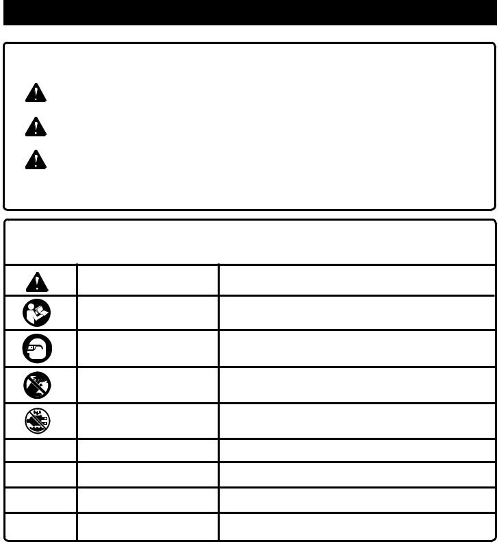
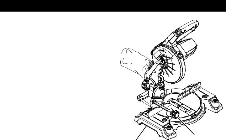
FEATURES
PRODUCT SPECIFICATIONS
Arbor......................................................................... |
5/8 in. |
Blade Diameter...................................................... |
7-1/4 in. |
No Load Speed..................................... |
4,500 r/min. (RPM) |
Motor................................................................ |
19.2 Volt DC |
Cutting Capacity with Miter at 0°/Bevel 0°:
Maximum lumber sizes...................... |
1-1/2 in. x 4-1/4 in. |
Cutting Capacity with Miter at 45°/Bevel 0°: |
|
Maximum lumber sizes............................. |
1-1/2 in. x 3 in. |
Cutting Capacity with Miter at 0°/Bevel 45°: |
|
Maximum lumber sizes...................... |
1-1/2 in. x 3-1/2 in. |
Cutting Capacity with Miter at 45°/Bevel 45°: |
|
Maximum lumber sizes............................. |
1-1/2 in. x 3 in. |
|
MITER |
|
LOCK LEVER |
|
“D” HANDLE |
|
SWITCH |
|
LOCK |
|
UPPER |
DUST |
BLADE |
BAG |
GUARD |
|
SWITCH |
|
TRIGGER |
|
LOWER |
|
BLADE |
|
GUARD |
|
“NO HANDS ZONE” |
BEVEL |
BOUNDARY LINE |
LOCK |
|
KNOB |
“NO HANDS |
|
|
|
ZONE” LABEL |
|
|
MITER |
|
|
SCALE |
MITER |
|
|
FENCE |
|
THROAT |
|
|
PLATE |
|
|
MITER |
|
BASE |
TABLE |
|
|
|
|
|
WORK |
|
|
CLAMP |
BLADE
WRENCH
BEVEL
SCALE
Fig. 1
8 — English
FEATURES
KNOW YOUR COMPOUND MITER SAW
See Figure 1.
The safe use of this product requires an understanding of the information on the tool and in this operator’s manual as well as a knowledge of the project you are attempting. Before use of this product, familiarize yourself with all operating features and safety rules.
7-1/4 in. BLADE
A 7-1/4 in. blade is included with the compound miter saw. It will cut materials up to 1-1/2 in. thick or 4-1/4 in. wide, depending upon the angle at which the cut is being made.
BEVEL LOCK KNOB
The bevel lock knob securely locks your compound miter saw at desired bevel angles. Positive stop adjustment screws have been provided on each side of the saw arm. These adjustment screws are for making fine adjustments at 0° and 45°.
LOCK 


 PIN
PIN 


MITER
LOCK LEVER 


REAR BRACKET/


 CARRYING HANDLE
“D” HANDLE
BLADE WRENCH STORAGE
A blade wrench is packed with the saw. One end of the wrench is a phillips screwdriver and the other end is a hex key. Use the hex key end when installing or removing blade and the phillips end when removing or loosening screws. A storage area for the blade wrench is located in the saw’s base.
MITER FENCE
The miter fence on the compound miter saw has been provided to hold your workpiece securely against when making all cuts.
MITER LOCK LEVER
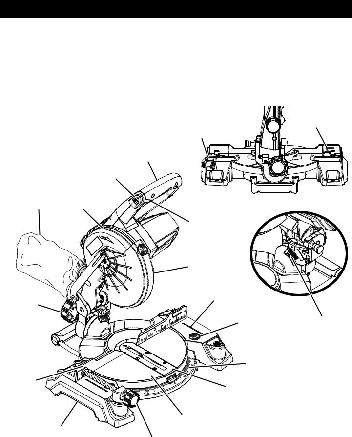
See Figure 2.
The miter lock lever securely locks the saw at desired miter angles.
SAW ARM LOCKED |
|
IN DOWN POSITION |
Fig. 2 |
|
SELF-RETRACTING LOWER BLADE GUARD
The lower blade guard is made of shock-resistant, seethrough plastic that provides protection from each side of the blade. It retracts over the upper blade guard as the saw is lowered into the workpiece.
SPINDLE LOCK BUTTON
See Figure 3.
The spindle lock button locks the spindle stopping the blade from rotating. Depress and hold the lock button while installing, changing, or removing blade.
POSITIVE STOPS ON MITER TABLE
Positive stops have been provided at 0°, 15°, 22-1/2°, 31.62°, and 45°. The 15°, 22-1/2°, 31.62°, and 45° positive stops have been provided on both the left and right side of the miter table.
REAR BRACKET/CARRYING HANDLE
See Figure 2.
For convenience when carrying or transporting the miter saw from one place to another, a carrying handle has been provided at the rear of the saw. To transport, turn off and remove the battery pack from the tool, then lower the saw arm and lock it in the down position. Lock saw arm by depressing the lock pin.


 SWITCH


 TRIGGER
SPINDLE
LOCK BUTTON
|
|
45 |
30 |
|
|
|
|
|
|
|
|
|
|
|
|
|
|
|
15 |
|
|
|
|
1 |
2 |
|
3 |
4 |
5 |
6 |
7 |
Fig. 3
9 — English
FEATURES
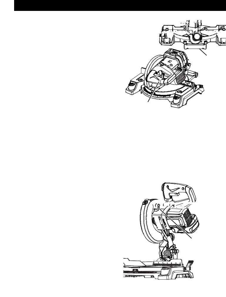
SWITCH TRIGGER
See Figure 4.
The saw will not start until you depress the switch lock with your thumb then squeeze the switch trigger. To prevent unauthorized use of the compound miter saw, remove the battery pack, and lock the switch in the off position. To lock the switch, install a padlock (not included) through the hole in the switch trigger. A lock with a long shackle of 5/16 in. diameter may be used. When the lock is installed and locked, the switch is inoperable. Store the padlock key in another location.
SWITCH
LOCK 


SWITCH |
PADLOCK |
TRIGGER |
|

 1
1
 45
45
2
30 |
|
|
|
|
15 |
|
|
|
|
3 |
4 |
5 |
6 |
7 |
Fig. 4
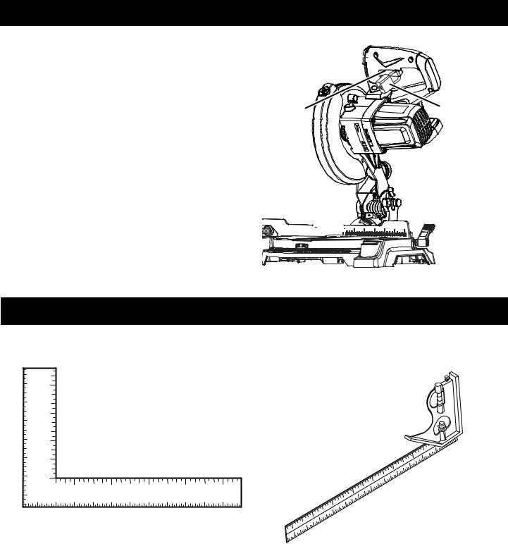
TOOLS NEEDED
The following tools (not included or drawn to scale) are needed for making adjustments or installing the blade:
COMBINATION SQUARE
FRAMING SQUARE
Fig. 5
10 — English
LOOSE PARTS LIST
The following items are included with your compound miter saw:
Dust Bag
Work Clamp
Blade Wrench
DUST
BAG
REAR BRACKET/
CARRYING HANDLE
Rear Bracket/Carrying Handle
Operator’s Manual (not shown)
WORK
CLAMP
BLADE
WRENCH
Fig. 6
 WARNING: The use of attachments or accessories not listed might be hazardous and could cause serious personal injury.
11 — English

ASSEMBLY
UNPACKING
This product requires assembly.
Carefully lift miter saw base from the carton by the “D” handle and the saw base, and place it on a level work surface.
 WARNING: Do not use this product if it is not completely assembled or if any parts appear to be missing or damaged. Use of a product that is not properly and completely assembled could result in serious personal injury.
If factory assembled, the saw has been shipped with the saw arm secured in the down position. To release the saw arm, push down on the top of the saw arm, cut the tie-wrap, and pull out on the lock pin.
Lift the saw arm by the handle. Hand pressure should remain on the saw arm to prevent sudden rise upon release of the tie wrap.
Inspect the tool carefully to make sure no breakage or damage occurred during shipping.
Do not discard the packing material until you have carefully inspected and satisfactorily operated the tool.
The saw is factory set for accurate cutting. After assembling it, check for accuracy. If shipping has influenced the settings, refer to specific procedures explained in this manual.
If any parts are damaged or missing, please call 1-800-932-3188 for assistance.
 WARNING: If any parts are damaged or missing do not operate this product until the parts are replaced. Use of this product with damaged or missing parts could result in serious personal injury.
 WARNING: Do not attempt to modify this tool or create accessories not recommended for use
with this tool. Any such alteration or modification is misuse and could result in a hazardous condition leading to possible serious personal injury.
 WARNING: To prevent accidental starting that could cause serious personal injury, always remove the battery pack from the tool when assembling parts.
 WARNING: Do not start the compound miter saw without checking for interference between the blade and the miter fence. Damage could result to the blade if it strikes the miter fence during operation of the saw.
INSTALLING THE REAR BRACKET/CARRYING HANDLE
See Figure 7.
 WARNING: A rear bracket is included with this miter saw to prevent tipping if the saw arm is released suddenly. Do not use this saw before installing the rear bracket and securely mounting the saw to a work surface or stand.
Remove the screws from the rear bracket/carrying handle and set aside.
Slide the bracket in the openings on the saw base, aligning the holes underneath the base with the holes in the bracket.
Insert the screws into the holes and tighten securely.
SCREW
SCREW
REAR BRACKET/
CARRYING HANDLE
Fig. 7
12 — English

ASSEMBLY
 WARNING: Always make sure the compound miter saw is securely mounted to a workbench or an approved workstand. Failure to heed this warning can result in serious personal injury.
MOUNTING HOLES
See Figure 8.
If not using a stand, the saw should be mounted to a firm supporting surface such as a workbench. Four bolt holes have been provided in the saw base for this purpose.
Each of the four mounting holes should be bolted securely using 1/4 in. machine bolts, lock washers, and hex nuts (not included). Bolts should be of sufficient length to accommodate the saw base, lock washers, hex nuts, and the thickness of the workbench. Tighten all four bolts securely.
The hole pattern for mounting to a workbench is shown in figure 8. Carefully check the workbench after mounting to make sure that no movement can occur during use. If any tipping, sliding, or walking is noted, secure the workbench to the floor before operating.
DUST BAG
See Figure 9.
A dust bag is provided for use on this miter saw. It fits over the exhaust port on the upper blade guard. To install, squeeze the two metal clips to open the mouth of the bag and slide it on the exhaust port. Release the clips. The metal ring in the bag should lock in between the grooves on the exhaust port. To remove the dust bag for emptying, simply reverse the above procedure.
DUST
BAG EXHAUST
PORT
Fig. 9
TRACE HOLES
AT THESE LOCATIONS FOR HOLE PATTERN
|
|
|
|
|
|
|
TRACE HOLES |
|
|
|
|
|
|
|
AT THESE LOCATIONS |
|
|
|
|
|
|
|
FOR HOLE PATTERN |
45 |
|
|
|
|
|
|
45 |
|
|
|
|
|
|
|
|
31 |
|
|
|
|
|
|
.6 |
.6 |
30 |
|
|
|
|
30 |
31 |
|
22.5 |
|
|
22.5 |
|
||
|
|
15 |
|
|
|
||
|
|
|
0 |
15 |
|
|
|
|
|
|
|
|
|
|
|
|
|
|
|
|
|
|
MOUNTING |
BASE |
|
|
|
|
|
SURFACE |
|
Fig. 8
13 — English
ASSEMBLY
WORK CLAMP
See Figure 10.
The work clamp provides greater control by clamping the workpiece to the fence. It also prevents the workpiece from creeping toward the saw blade. This is very helpful when cutting compound miters.
Depending on the cutting operation and the size of the workpiece, it may be necessary to use a C-clamp instead of the work clamp to secure the workpiece prior to making the cut.
 WARNING: In some operations, the work clamp assembly may interfere with the operation of the blade guard assembly. Always make sure there is no interference with the blade guard prior to beginning any cutting operation to reduce the risk of serious personal injury.
To install the work clamp:
Place the shaft of the work clamp in either hole on the saw table base.
Rotate the knob on the work clamp to move it in or out as needed.
|
45 |
|
WORK |
BASE |
CLAMP |
Fig. 10
14 — English
ASSEMBLY
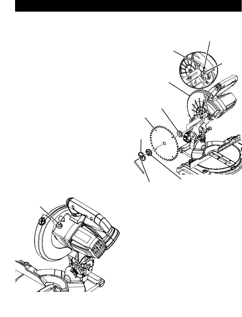
TO INSTALL/REPLACE THE BLADE
See Figures 11 - 12.
 WARNING: A 7-1/4 in. blade is the maximum blade capacity of the saw. Never use a blade that is too thick to allow outer blade washer to engage with the flats on the spindle. Larger blades will come in contact with the blade guards, while thicker blades will prevent the blade bolt from securing the blade on the spindle. Either of these situations could result
in a serious accident and can cause serious personal injury.
Remove the battery pack from the tool.
Raise the saw arm.
Rotate lower blade guard up and remove blade bolt cover screw. Rotate blade bolt cover up and back to expose the blade bolt.
Depress the spindle lock button and rotate the blade bolt until the spindle locks.
Using the wrench provided, loosen and remove the blade bolt.
NOTE: The blade bolt has left hand threads. Turn blade bolt clockwise to loosen.
Remove outer blade washer. Do not remove inner blade washer.
Wipe a drop of oil onto inner blade washer and outer blade washer where they contact the blade.
 WARNING: If inner blade washer has been removed, replace it before placing blade on spindle. Failure to do so could cause an accident since blade will not tighten properly.
SPINDLE LOCK
BUTTON
Fig. 11
BLADE
BOLT
COVER
LOWER
BLADE
GUARD
INNER BLADE
WASHER WITH DOUBLE “D” FLATS
BLADE
TO
LOOSEN
 TO
TO
TIGHTEN
BLADE
BOLT
NOTE: BEFORE USE,
REPLACE SCREW AND
TIGHTEN SECURELY
TO PREVENT GUARD
MOVEMENT
BLADE BOLT
COVER
SCREW


 FLAT(S)
ON SPINDLE
45
OUTER BLADE
WASHER WITH
DOUBLE “D” FLATS
Fig. 12
Fit saw blade inside lower blade guard and onto spindle. The blade teeth point downward at the front of saw as shown in figure 12.
Replace outer blade washer. Double “D” flats on blade washers align with flats on spindle.
Depress spindle lock button and replace blade bolt.
NOTE: The blade bolt has left hand threads. Turn blade bolt counterclockwise to tighten.
 CAUTION: Always install the blade with the blade teeth and the arrow printed on the side of the blade pointing down at the front of the saw. The direction of blade rotation is also stamped with an arrow on the upper blade guard.
Tighten blade bolt securely.
Replace the lower blade guard and blade bolt cover.
Replace blade bolt cover screw and tighten securely.
15 — English
|
ASSEMBLY |
|
SOCKET HEAD |
SOCKET HEAD |
SCREW(S) |
SCREW(S) |
MITER |
|
LOCK |
|
LEVER MITER |
|
FENCE |
45 |
|
|
|
|
|
|
45 |
|
|
|
|
|
|
|
|
31 |
|
|
|
|
|
|
.6 |
.6 |
30 |
|
|
|
|
30 |
31 |
|
22.5 |
|
|
22.5 |
|
||
|
|
15 |
|
|
|
||
|
|
|
0 |
15 |
|
|
|
|
|
|
|
|
|
|
MITER
FENCE
Fig. 13 NOTE: Many of the illustrations in this manual show only portions of the compound miter saw. This is intentional
so that we can clearly show points being made in the illustrations. Never operate the saw without all guards securely in place and in good operating condition.
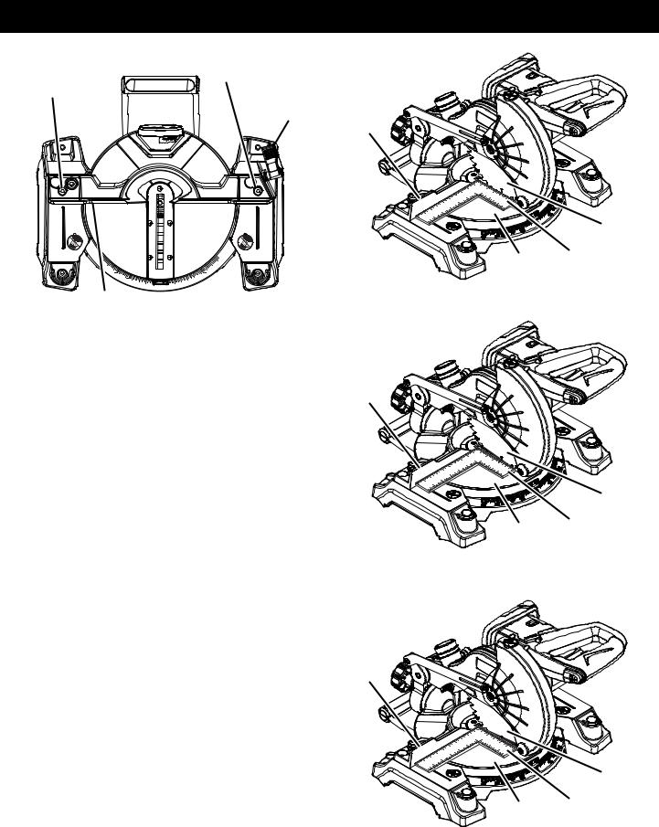
SQUARING THE BLADE TO THE FENCE
See Figures 13 - 16.
Remove the battery pack from the tool.
Pull the saw arm all the way down and engage the lock pin to hold the saw arm in transport position.
Lift the miter lock lever.
Rotate the miter table until the pointer aligns with zero on the miter scale.
Push the miter lock lever down to lock the miter table.
Lay a square flat on the miter table. Place one leg of the square against the fence. Slide the other leg of the square against the flat part of saw blade.
NOTE: Make sure that the square contacts the flat part of the saw blade, not the blade teeth.
The edge of the square and the saw blade should be parallel as shown in figure 14.
If the front or back edge of the saw blade angles away from the square as shown in figures 15 and 16, adjustments are needed.
Using the blade wrench, loosen the socket head screws that secure the miter fence to the miter table.
See figure 13.
Rotate the miter fence left or right until the saw blade is parallel with the square.
Retighten the screws securely and recheck the blade- to-fence alignment.
The saw has two scale indicators, one on the bevel scale and one on the miter scale. After squaring adjustments have been made, it may be necessary to loosen the indicator screws and reset them to zero.
BLADE
MITER FRAMING
TABLE SQUARE
VIEW OF BLADE SQUARE WITH FENCE |
Fig. 14 |
|
MITER
FENCE
BLADE
MITER FRAMING
TABLE SQUARE
VIEW OF BLADE NOT SQUARE WITH FENCE,
ADJUSTMENTS ARE REQUIRED
Fig. 15
MITER
FENCE
BLADE
MITER |
FRAMING |
|
SQUARE |
|
|
TABLE |
|
|
|
|
|
VIEW OF BLADE NOT SQUARE WITH FENCE, |
|
|
ADJUSTMENTS ARE REQUIRED |
Fig. 16 |
|
|
|
|
16 — English

SQUARING THE BLADE TO THE MITER TABLE
See Figures 17 - 20.
Remove the battery pack from the tool.
Pull the saw arm all the way down and engage the lock pin to hold the saw arm in transport position.
Lift the miter lock lever.
Rotate the miter table until the pointer aligns with zero on the miter scale.
Push the miter lock lever down to lock the miter table.
Loosen bevel lock knob and set saw arm at 0° bevel (blade set 90° to miter table). Tighten bevel lock knob.
Place a square against the miter table and the flat part of saw blade.
NOTE: Make sure that the square contacts the flat part of the saw blade, not the blade teeth.
Rotate the blade by hand and check the blade-to-table alignment at several points.
The edge of the square and the saw blade should be parallel as shown in figure 18.
If the top or bottom of the saw blade angles away from the square as shown in figures 19 and 20, adjustments are needed.
Loosen the bevel lock knob.
Adjust positive stop adjustment screw to bring saw blade into alignment with the square. See Positive Stop Adjustment in the Adjustments section.
Retighten bevel lock knob. Recheck blade-to-table alignment.
NOTE: The above procedure can be used to check blade squareness of the saw blade to the miter table at both 0° and 45° angles.
The saw has two scale indicators, one on the bevel scale and one on the miter scale. After squaring adjustments have been made, it may be necessary to loosen the indicator screws and reset them to zero.
|
SCALE |
|
INDICATOR |
|
MITER |
|
SCALE |
|
INDICATOR |
BEVEL |
SCREW |
SCALE |
Fig. 17 |
|
BEVEL 


 LOCK
LOCK 


 KNOB
KNOB 


MITER 


FENCE
COMBINATION
SQUARE
BLADE
MITER
TABLE
CORRECT VIEW OF BLADE SQUARE WITH MITER TABLE
BEVEL 


 LOCK
LOCK 


 KNOB
KNOB 


MITER
FENCE
COMBINATION
SQUARE
Fig. 18
BLADE
MITER
TABLE
VIEW OF BLADE NOT SQUARE WITH MITER TABLE,
ADJUSTMENTS ARE REQUIRED
Fig. 19
BEVEL
LOCK 


KNOB
MITER
FENCE
BLADE
COMBINATION |
MITER |
TABLE |
|
SQUARE |
|
VIEW OF BLADE NOT SQUARE WITH MITER TABLE,
ADJUSTMENTS ARE REQUIRED
Fig. 20
17 — English
OPERATION
 WARNING: Do not allow familiarity with tools to make you careless. Remember that a careless fraction of a second is sufficient to inflict serious injury.
 WARNING: Always wear eye protection with side shields marked to comply with ANSI Z87.1. Failure to do so could result in objects being thrown into your eyes, resulting in possible serious injury.
 WARNING: Do not use any attachments or accessories not recommended by the manufacturer of this tool. The use of attachments or accessories not recommended can result in serious personal injury.
APPLICATIONS
This product has been designed only for the purposes listed below:
Cross cutting wood and plastic (do not cut metals, ceramics, or masonry products)
Cross cutting miters, joints, etc. for picture frames moldings, door casings, and fine joinery
Bevel cutting and compound cutting
NOTE: The blade provided is fine for most wood cutting operations, but for fine joinery cuts or cutting plastic, use one of the accessory blades available from the dealer.
 WARNING: Before starting any cutting operation, clamp or bolt the compound miter saw to a workbench or an approved workstand. Never operate the miter saw on the floor or in a crouched position. Failure to heed this warning can result in serious personal injury.
 WARNING: To avoid serious personal injury, always lock the miter lock lever before making a cut. Failure to do so could result in movement of the control arm or miter table while making a cut.
 WARNING: To avoid serious personal injury, keep hands outside the no hands zone, at least 3 in. from the blade. Never perform any cutting operation freehand (without holding workpiece against the fence). The blade could grab the workpiece if it slips or twists.
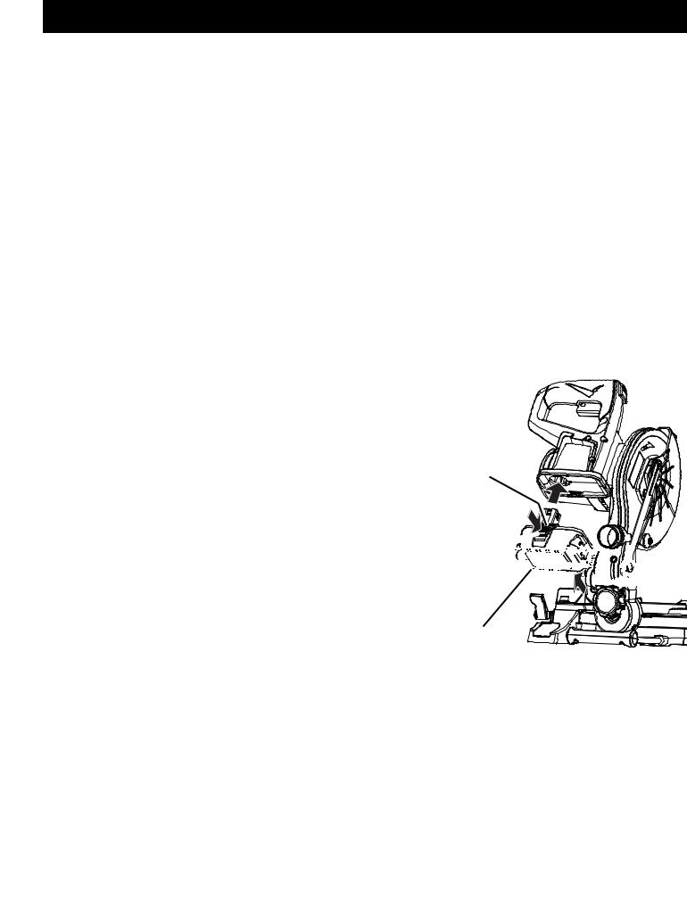
TO INSTALL BATTERY PACK
See Figure 21.
Place battery pack in the saw. Align raised rib on battery pack with groove inside saw.
Make sure the latches on each side of the battery pack snap in place and that the battery pack is secured in the tool before beginning operation.
 WARNING: Always remove battery pack from your tool when you are assembling parts, making adjustments, cleaning, or when not in use. Removing battery pack will prevent accidental starting that could cause serious personal injury.
TO REMOVE BATTERY PACK
See Figure 21.
Locate latches on each side of the battery pack. Depress the latches to release the battery pack from the tool.
Remove the battery pack from the tool.
LATCHES
DEPRESS LATCHES 


 TO RELEASE


 BATTERY PACK


BATTERY
PACK
Fig. 21
18 — English
 Loading...