

Page 1

NWA3000-N Series
Wireless N Business WLAN 3000 Series Access Point
Default Login Details
IP Address https://192.168.1.2
User Name admin
Password 1234
Version 2.23
Edition 1, 1/2011
www.zyxel.com
www.zyxel.com
Copyright © 2011
ZyXEL Communications Corporation
Page 2

Page 3

About This User's Guide
About This User's Guide
Intended Audience
This manual is intended for people who want to configure a NWA3000-N series AP
using the web configurator. You should have at least a basic knowledge of TCP/IP
networking concepts and topology.
Related Documentation
•Quick Start Guide
The Quick Start Guide is designed to help you get up and running right away. It
contains information on setting up your network and configuring for Internet
access.
• Support Disc
Refer to the included CD for support documents.
• ZyXEL Web Site
Please refer to www.zyxel.com
product certifications.
for additional support documentation and
User Guide Feedback
Help us help you. Send all User Guide-related comments, questi ons or suggestions
for improvement to the following address, or use e-mail instead. Thank you!
The Technical Writing Team,
ZyXEL Communications Corp.,
6 Innovation Road II,
Science-Based Industrial Park,
Hsinchu, 300, Taiwan.
E-mail: techwriters@zyxel.com.tw
NWA3000-N Series User’s Guide
3
Page 4

Document Conventions
Warnings and Notes
These are how warnings and notes are shown in this User’s Guide.
Warnings tell you about things that could harm you or your device.
Note: Notes tell you other important information (for example, other things you may
need to configure or helpful tips) or recommendations.
Syntax Conventions
• The product in this book may be referred to as the “NWA3000-N series AP”, the
“device”, the “AP”, or the “system” in this User’s Guide.
• Product labels, screen names, field labels and field choices are all in bold font.
Document Conventions
• A key stroke is denoted by square brackets and uppercase text, for example,
[ENTER] means the “enter” or “ret urn” key on your keyboard.
• “Enter” means for you to type one or more characters and then press the
[ENTER] key. “Select” or “choose” means for you to use one of the predefined
choices.
• A right angle bracket ( > ) within a screen name denotes a mouse click. For
example, Maintenance > Status > Show Statistics means you first click
Maintenance in the navigation panel, then the Status sub menu and finally the
Show Statistics button to get to that screen.
• Units of measurement may denote the “metric” value or the “scientific” value.
For example, “k” for kilo may denote “1000” or “1024”, “M” for mega may
denote “1000000” or “1048576” and so on.
• “e.g.,” is a shorthand for “for instance”, and “i.e.,” means “that is” or “in other
words”.
• Screens reproduced here for demonstration purposes may not exactly match
the screens on your device.
4
NWA3000-N Series User’s Guide
Page 5
Document Conventions
Icons Used in Figures
Figures in this User’s Guide may use the following generic icons. The NWA3000-N
series AP icon is not an exact representation of your device.
NWA3000-N series AP Computer Notebook computer
Server Printer Firewall
Telephone Switch Router
NWA3000-N Series User’s Guide
5
Page 6

Safety Warnings
• Do NOT use this product near water, for example, in a wet basement or near a swimming
pool.
• Do NOT expose your device to dampness, dust or corrosive liquids.
• Do NOT store things on the device.
• Do NOT install, use, or service this device during a thunderstorm. There is a remote risk
of electric shock from lightning.
• Connect ONLY suitable accessories to the device.
• ONLY qualified service personnel should service or disassemble this device.
• Make sure to connect the cables to the correct ports.
• Place connecting cables carefully so that no one will step on them or stumble over them.
• Always disconnect all cables from this device before servicing or disassembling.
• Use ONLY an appropriate power adaptor or cord for your device.
• Connect the power adaptor or cord to the right supply voltage (for example, 110V AC in
North America or 230V AC in Europe).
• Do NOT allow anything to rest on the power adaptor or cord and do NOT place the
product where anyone can walk on the power adaptor or cord.
• Do NOT use the device if the power adaptor or cord is damaged as it might cause
electrocution.
• If the power adaptor or cord is damaged, remove it from the power outlet.
• Do NOT attempt to repair the power adaptor or cord. Contact your local vendor to order a
new one.
• Do not use the device outside, and make sure all the connections are indoors. There is a
remote risk of electric shock from lightning.
• “Not to remove the plug and plug into a wall outlet by itself; always attach the plug to the
power supply first before insert into the wall.”
• (In other words, do NOT remove the plug and connect it to a power outlet by itself;
always attach the plug to the power adaptor first before connecting it to a power outlet.)
• Antenna Warning! This device meets ETSI and FCC certification requirements when using
the included antenna(s). Only use the included antenna(s).
• If you wall mount your device, make sure that no electrical lines, gas or water pipes will
be damaged.
• The PoE (Power over Ethernet) devices that supply or receive power and their connected
Ethernet cables must all be completely indoors.
• The indoors versions of this product are for indoor use only (utilisation intérieure
exclusivement).
Safety Warnings
6
This product is recyclable. Dispose of it properly.
NWA3000-N Series User’s Guide
Page 7

Table of Contents
Table of Contents
About This User's Guide..........................................................................................................3
Document Conventions............................................................................................................4
Safety Warnings ........................................................................................................................6
Table of Contents......................................................................................................................7
Part I: User’s Guide................................................................................ 15
Chapter 1
Introduction.............................................................................................................................17
1.1 Overview ............... ............................................. .... ... ... ... .... ... ............................................. 17
1.2 Applications for the NWA3000-N series AP ..................................... .... ... ... ... .... ... ... ... .......... 18
1.2.1 Bridge / Repeater ....................................................................................................... 18
1.2.2 AP + Bridge ......................... ... ... ... .... ... ... ............................................. .... ... ... ... ... ....... 22
1.2.3 MBSSID .............................................. ... ... .............................................. ... ... ... ..........22
1.3 Management Mode .................... ... ... ... ... .... ................................................ ... .... ................... 23
1.4 Ways to Manage the NWA3000-N series AP ............................... ... .... ... ... ... .... ... ... ... .......... 24
1.5 Good Habits for Managing the NWA3000-N series AP ....................................................... 25
1.6 Hardware Connections ........................................................................................................ 26
1.7 LEDs ......................... .... ............................................. ... ... .... ................................................ 27
1.8 Starting and Stopping the NWA3000-N series AP ............................................................... 29
Chapter 2
The Web Configurator............................................................................................................31
2.1 Overview ............. ............................................. ... .... ... ... ... .... ................................................ 31
2.2 Access ............................................................................. .... ... ... .......................................... 32
2.3 The Main Screen ................................................................................................................. 33
2.3.1 Title Bar .................................. ... ............................................. .... ... ... .......................... 34
2.3.2 Navigation Panel .......... .... ... ... ... ................................................................................. 34
2.3.3 Warning Messages ..................................................................................................... 38
2.3.4 Site Map .......... .... ... ... ... .... ............................................. ... ... ... .... ... ... ... ....................... 38
2.3.5 Object Reference ......... .... ... ............................................. ... ... .... ... ... ... ....................... 38
2.3.6 Tables and Lists .. ... ... ... .............................................. ... ... ... ... .... ... ... ..........................44
Chapter 3
Configuration Basics..............................................................................................................49
NWA3000-N Series User’s Guide
7
Page 8

Table of Contents
3.1 Overview ............. ............................................. ... .... ... ... ... .... ................................................ 49
3.2 Object-based Configuration .......................................................................... .... ... ... .............49
3.3 Feature Configuration Overview .......................................................................................... 49
3.3.1 Feature ...................................... ... .... ... ... ... .... ... ............................................. ... ... ....... 50
3.3.2 MGNT Mode ........................ ... ... ............................................. .... ... ... ... .... ... ................50
3.3.3 LAN Setting ......... ... ... ... .............................................. ... ... ... ... .... ... ............................. 50
3.3.4 Wireless .................................................... .... ... ... ............................................. ... ....... 50
3.3.5 Device HA ................. ... .............................................. ... ... ... ... .... ... ............................. 51
3.4 Objects ............................................ ... ... .... ............................................. ... ... .... ... ................51
3.4.1 User ........................ ............................................. ... .... ... ............................................. 51
3.4.2 AP Profile ............... ... ............................................. .... ... ... ... ... .... ................................ 52
3.4.3 MON Profile ...................... ... ... ............................................. ... .... ... ... ... .... ................... 52
3.5 System ............. ............................................. ... ... .... ............................................. ................52
3.5.1 WWW, SSH, TELNET, FTP, SNMP, and Auth. Server ............................................... 52
3.5.2 Logs and Reports ....................................................................................................... 53
3.5.3 File Manager .................... ... ... ... ............................................. .... ... ... ... .... ... ... ... ... .... ... 53
3.5.4 Diagnostics ................ ... .... ... ... ... ... .............................................. ... ... ... .... ................... 53
3.5.5 Shutdown ............... ... ............................................. .... ... ... ... ... .... ................................ 53
Chapter 4
Tutorials..................................................................................................................................55
4.1 Sample Network Setup ....................... ... .... ... ... ... .... ... ... .......................................................55
4.1.1 Set the Management Modes ......................................................................................56
4.1.2 Set the LAN IP Address and Management VLAN (vlan99) ........................................ 57
4.1.3 Set Up Wireless User Authentication ............ ............................................................. 58
4.1.4 Create the AP Profiles (staff, guest) ........................................................................... 60
4.2 Rogue AP Detection .................................. ... ... ... .... ... ..........................................................63
4.2.1 Rogue AP Containment ............................................................................................. 67
4.3 Load Balancing .......................... ... ... ... ............................................. .... ... ... ... .... ................... 69
4.4 Dynamic Channel Selection ................................................................................................ 70
Part II: Technical Reference.................................................................. 73
Chapter 5
Dashboard............................................................................................................................75
5.1 Overview ............. ............................................. ... .... ... ... ... .... ................................................ 75
5.1.1 What Yo u Can Do in this Chapter .............................................................................. 75
5.2 Dashboard .................................... ... ... ............................................. .... ... ... ... .... ... ................ 76
5.2.1 CPU Usage ............... ... .............................................. ... ... ... ... .... ... .............................80
5.2.2 Memory Usage .................................... ... ... .... ... ... ... .... ................................................ 81
8
NWA3000-N Series User’s Guide
Page 9

Table of Contents
Chapter 6
Monitor.................................................................................................................................83
6.1 Overview ............. ............................................. ... .... ... ... ... .... ................................................ 83
6.1.1 What Yo u Can Do in this Chapter .............................................................................. 83
6.2 What You Need to Know ..................................... .... ... ... .......................................................83
6.3 LAN Status .......................................... ... .... ... ... ... .... ... ............................................. ............. 84
6.3.1 LAN Status Graph ..................................................................................................... 86
6.4 AP List ............ ............................................. ... ... .... ... ... ... .................................................... 87
6.4.1 Station Count of AP .................................................................................................. 89
6.5 Radio List ..................... ... ............................................. ... .... ... ... ... ... .................................... 89
6.5.1 AP Mode Radio Information ....................................................................................... 91
6.6 Station List ............................ .... ... ... ............................................. ... .... ... ... ... .... ................... 93
6.7 Rogue AP ........ ............................................. ... ... .... ... ... ... .................................................... 94
6.8 Legacy Device Info .............................................................................................................. 95
6.8.1 Legacy Device Info Add or Edit .................................................................................. 96
6.9 View Log .......................... ... ... .... ... ... ............................................. ... .... ... ... .......................... 96
6.10 View AP Log ................................................................................................................... 100
Chapter 7
Management Mode................................................................................................................103
7.1 Overview ............. ............................................. ... .... ... ... ... .... .............................................. 103
7.2 About CAPWAP ............ ... ... ... .... ... ... .................................................................................. 103
7.2.1 CAPWAP Discovery and Management ......................................... ... ... .... ................. 104
7.2.2 Managed AP Finds the Controller ............................................................................104
7.2.3 CAPWAP and IP Subnets ...... ... ... .... ... ... ................................................. ... ... ... ... .....104
7.2.4 Notes on CAPWAP .......... ... ... ... ... .... ............................................. ... ... .... ... ... ... ........105
7.3 The Management Mode Screen ........................................................................................ 105
Chapter 8
LAN Setting ...........................................................................................................................107
8.1 LAN Setting Overview .......................................................................................................107
8.1.1 What Yo u Can Do in this Chapter ............................................................................ 107
8.1.2 What You Need to Know ..................................... ... .... ... ........................................... 107
8.2 LAN Setting ............................................... ... ... ... .... ...........................................................108
8.2.1 Add or Edit a DNS Setting ........................................................................................110
Chapter 9
Wireless.................................................................................................................................111
9.1 Overview ............. ............................................. ... .... ... ... ... .... ...............................................111
9.1.1 What Yo u Can Do in this Chapter .............................................................................111
9.1.2 What You Need to Know ..................................... ... .... ... ............................................111
9.2 Controller ................................... ... ... ............................................. ... .... ... ... ... .... ..................112
9.3 AP Management .............................. ... ... .... ... ... ... .... ... ... ... ...................................................113
NWA3000-N Series User’s Guide
9
Page 10

Table of Contents
9.3.1 Edit AP List ...............................................................................................................115
9.4 MON Mode ............................................ .... ... ... ... .... ............................................. ... ... .........116
9.4.1 Add/Edit Rogue/Friendly List .....................................................................................118
9.5 Load Balancing .......................... ... ... ... ............................................. .... ... ... ... .... ... ... ............119
9.5.1 Disassociating and Delaying Connections ............................................................... 120
9.6 DCS ...................................... .............................................. ... ... ... ..................................... 122
9.7 Technical Reference .............. .... ... ... ... ... ............................................................................ 124
Chapter 10
Device HA.............................................................................................................................127
10.1 Overview .......................................................................................................................... 127
10.1.1 What You Can Do in this Chapter .......................................................................... 127
10.1.2 What You Need to Know ........................................................................................ 128
10.1.3 Before You Begin ...................................................................................................128
10.2 Device HA General ..........................................................................................................129
10.3 Active-Passive Mode .......................................................................................................131
10.3.1 Edit Monitored Interface ................. ........................................................................ 134
10.4 Technical Reference ........................................................................................................135
Chapter 11
User......................................................................................................................................137
11.1 Overview .......................................................................................................................... 137
11.1.1 What You Can Do in this Chapter ................................ ... ... ... .... ... ........................... 137
11.1.2 What You Need To Know ........................................................................................137
11.2 User Summary .................................................................................................................138
11.2.1 Add/Edit User ......................................................................................................... 139
11.3 Setting ............................................................................................................................. 141
11.3.1 Edit User Authentication Timeout Settings .............................................................144
Chapter 12
AP Profile............................................................................................................................147
12.1 Overview .......................................................................................................................... 147
12.1.1 What You Can Do in this Chapter .......................................................................... 147
12.1.2 What You Need To Know ....................................................................................... 147
12.2 Radio ............................................................................................................................... 149
12.2.1 Add/Edit Radio Profile ............................................................................................ 150
12.3 SSID ............................................................................................................................... 154
12.3.1 SSID List ................................................................................................................154
12.3.2 Security List ............................................................................................................ 158
12.3.3 MAC Filter List ........................................................................................................ 161
Chapter 13
MON Profile ........................................................................................................................165
10
NWA3000-N Series User’s Guide
Page 11

Table of Contents
13.1 Overview .......................................................................................................................... 165
13.1.1 What You Can Do in this Chapter .......................................................................... 165
13.1.2 What You Need To Know ....................................................................................... 165
13.2 MON Profile ..................................................................................................................... 166
13.2.1 Add/Edit MON Profile ............................................................................................. 167
13.3 Technical Reference ........................................................................................................168
Chapter 14
Certificates .........................................................................................................................171
14.1 Overview .......................................................................................................................... 171
14.1.1 What You Can Do in this Chapter .......................................................................... 171
14.1.2 What You Need to Know ........................................................................................ 171
14.1.3 Verifying a Certificate ............................................................................................. 173
14.2 My Certificates ................................................................................................................ 175
14.2.1 Add My Certificates ................................................................................................177
14.2.2 Edit My Certificates ................................................................................................181
14.2.3 Import Certificates ................................................................................................. 184
14.3 Trusted Certificates .......................................................................................................... 185
14.3.1 Edit Trusted Certificates .............................. ........................................................... 187
14.3.2 Import Trusted Certificates ............................. ... ... .... ... ........................................... 190
14.4 Technical Reference ........................................................................................................191
Chapter 15
System..................................................................................................................................193
15.1 Overview .......................................................................................................................... 193
15.1.1 What You Can Do in this Chapter .......................................................................... 193
15.2 Host Name ....................................................................................................................... 194
15.3 Date and Time ................................................................................................................ 194
15.3.1 Pre-defined NTP Time Servers List ............................................. ... ... .... ... ... ... ... .... . 197
15.3.2 Time Server Synchronization ................................................................................. 198
15.4 Console Speed ................................................................................................................ 199
15.5 WWW Overview ..............................................................................................................200
15.5.1 Service Access Limitations .................................................................................... 200
15.5.2 System Timeout .....................................................................................................200
15.5.3 HTTPS ...................................................................................................................200
15.5.4 Configuring WWW Service Control ........................................................................ 201
15.5.5 HTTPS Example ....................................................................................................203
15.6 SSH ..............................................................................................................................209
15.6.1 How SSH Works ......................................................... ... ... ... .... ... ... ........................ 210
15.6.2 SSH Implementation on the NWA3000-N series AP ......... ... .... ... ... ... .... ... ... ... ... .... ..211
15.6.3 Requirements for Using SSH ..................................................................................211
15.6.4 Configuring SSH ....................................................................................................212
15.6.5 Examples of Secure Telnet Using SSH .................................................................. 213
NWA3000-N Series User’s Guide
11
Page 12

Table of Contents
15.7 Telnet .............................................................................................................................. 214
15.8 FTP ................................................................................................................................. 215
15.9 SNMP .............................................................................................................................217
15.9.1 Supported MIBs ..................................................................................................... 218
15.9.2 SNMP Traps ........................................................................................................... 218
15.9.3 Configuring SNMP .................................................................................................219
15.9.4 Adding or Editing an SNMPv3 User Profile ................. ........................................... 220
15.10 Internal RADIUS Server ................................................................................................ 221
15.10.1 Configuring the Internal RADIUS Server ............................................................. . 222
15.10.2 Adding or Editing a Trusted AP Profile .................................................................224
15.11 Technical Reference ................. ... ... ................................................. ... ... ... .... ... ... ... ... .....225
Chapter 16
Log and Report ....................................................................................................................227
16.1 Overview .......................................................................................................................... 227
16.1.1 What You Can Do In this Chapter .......................................................................... 227
16.2 Email Daily Report ........................................................................................................... 227
16.3 Log Setting ..................................................................................................................... 229
16.3.1 Log Setting Summary ............................................................................................. 230
16.3.2 Edit Log Settings ...................................................................................................232
16.3.3 Edit Remote Server ............................................................................................... 236
16.3.4 Active Log Summary ............................................................................................. 238
Chapter 17
File Manager........................................................................................................................241
17.1 Overview .......................................................................................................................... 241
17.1.1 What You Can Do in this Chapter .......................................................................... 241
17.1.2 What you Need to Know ........................................................................................ 241
17.2 Configuration File ............................................................................................................ 243
17.3 Firmware Package ..........................................................................................................248
17.4 Shell Script ..................................................................................................................... 249
Chapter 18
Diagnostics..........................................................................................................................253
18.1 Overview .......................................................................................................................... 253
18.1.1 What You Can Do in this Chapter .......................................................................... 253
18.2 Diagnostics ..................................................................................................................... 253
18.3 Packet Capture ...............................................................................................................254
18.3.1 Packet Capture Files .................................. ... ............................................. ... ... .... . 256
18.3.2 Example of Viewing a Packet Capture File .......................... .... ... ... ... .... ... ... ...........257
18.4 Wireless Frame Capture .. ... .............................................. ... ... ... ... .................................. 258
18.4.1 Wireless Frame Capture Files ............................................................................... 261
12
NWA3000-N Series User’s Guide
Page 13

Table of Contents
Chapter 19
Reboot....................................................................................................................................263
19.1 Overview .......................................................................................................................... 263
19.1.1 What You Need To Know ....................................................................................... 263
19.2 Reboot .............................................................................................................................263
Chapter 20
Shutdown........................................................................................................................265
20.1 Overview .......................................................................................................................... 265
20.1.1 What You Need To Know ....................................................................................... 265
20.2 Shutdown .........................................................................................................................265
Chapter 21
Troubleshooting....................................................................................................................267
21.1 Overview .......................................................................................................................... 267
21.2 Power, Hardware Connections, and LEDs .............................. ... ... .... ... ... ... .... ... ... ... ........267
21.3 NWA3000-N series AP Access and Login ....................................................................... 268
21.4 Internet Access ................................................................................................................ 270
21.5 Wireless AP Troubleshooting .......................................................................................... 272
21.6 Resetting the NWA3000-N series AP .............................................................................. 277
21.7 Getting More Troubleshooting Help ................................................................................. 278
Chapter 22
Product Specifications.........................................................................................................279
22.1 Wall-Mounting Instructions .............................................................................................. 282
Appendix A Log Descriptions...............................................................................................285
Appendix B Importing Certificates........................................................................................305
Appendix C Wireless LANs..................................................................................................319
Appendix D Open Software Announcements.......................................................................333
Appendix E Legal Information..............................................................................................373
Index.......................................................................................................................................379
NWA3000-N Series User’s Guide
13
Page 14

Table of Contents
14
NWA3000-N Series User’s Guide
Page 15

PART I
User’s Guide
15
Page 16

16
Page 17

CHAPTER 1
Introduction
1.1 Overview
Your NWA3000-N series AP’s business-class reliability, SMB features, and
centralized wireless management make it ideally suited for advanced service
delivery in mission-critical networks. The NWA3000-N series AP provides secure
mobility across the 2.4GHz and 5GHz spectrums and the IEEE 802.11n standard’s
high bandwidth to support high-performance applications. It uses Multiple BSSID
and VLAN to provide up to eight simultaneous independent virtual APs.
Additionally, innovations in roaming technology and QoS features eliminate voice
call disruptions. It can serve as an AP, Bridge, Repeater or even as an RF monitor
to search for rouge APs to help eliminate network threats.
The NWA3000-N series AP controls network access with Media Access Control
(MAC) address filtering, rogue Access Point (AP) detection and containment, and
an internal authentication server. It also provides a high level of network traffic
security, supporting IEEE 802.1x, Wi-Fi Protected Access (WPA), WPA2 and Wired
Equivalent Privacy (WEP) data encryption.
A NWA3000-N series AP can manage up to 24 other NWA3000-N series APs on
your network. Configuration profiles let you easily use different WLAN and s ecurity
settings for various virtual and managed APs.
Your NWA3000-N series AP is easy to install, configure and use. The embedded
Web-based configurator enables simple, straightforward management and
maintenance. See the Quick Start Guide for how to make hardware connections.
NWA3000-N Series User’s Guide
17
Page 18

Chapter 1 Introduction
1.2 Applications for the NWA3000-N series AP
The NWA3000-N series AP can be configured to use the following operat ing modes
•Bridge / Repeater
•AP + Bridge
•MBSSID
Applications for each operating mode are shown below.
Note: A different channel should be configured for each WLAN interface to reduce the
effects of radio interference.
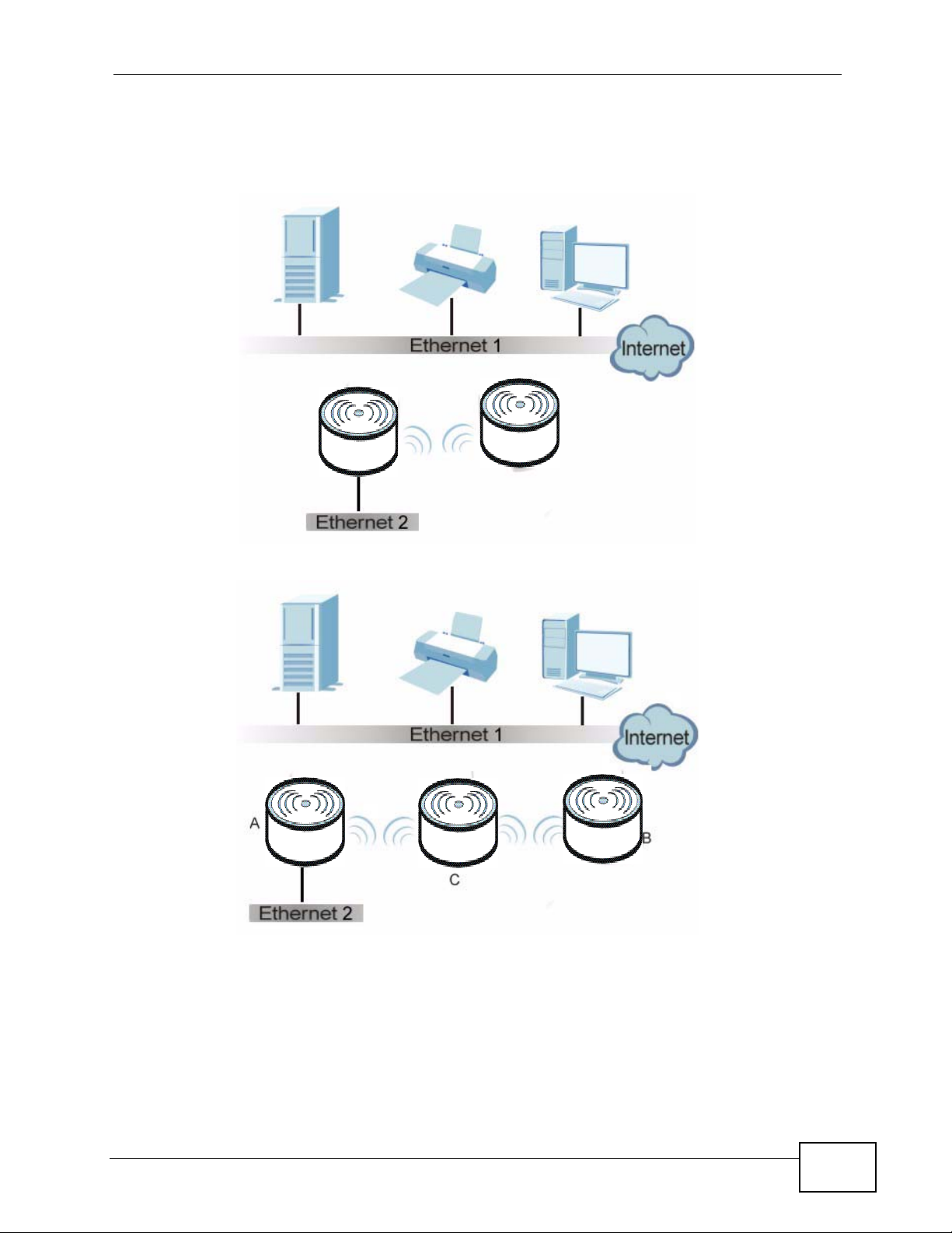
1.2.1 Bridge / Repeater
The NWA3000-N series AP can act as a wireless network bridge and establish
wireless links with other APs. In the figure below, the two NWA3000-N series APs
(A and B) are connected to independent wired networks and have a bridge
connection (A can communicate with B) at the same time. A NWA3000-N series AP
in repeater mode (C) has no Ethernet connection. When the NWA3000-N series AP
is in bridge mode, you should enable Spanning Tree Protocol (STP) to prevent
bridge loops.
When the NWA3000-N series AP is in Bridge / Repeater mode, security between
APs (the Wireless Distribution System or WDS) is independent of the security
between the wireless stations and the AP. If you do not enable WDS security,
traffic between APs is not encrypted. When WDS security is enabled, both APs
must use the same pre-shared key.
Once the security settings of peer sides match one another, the connection
between devices is made.
18
NWA3000-N Series User’s Guide
Page 19
Chapter 1 Introduction
At the time of writing, WDS security is compatible with other ZyXEL access points
only. Refer to your other access point’s documentation for details.
Figure 1 Bridge Application
Figure 2 Repeater Application
NWA3000-N Series User’s Guide
19
Page 20
Chapter 1 Introduction
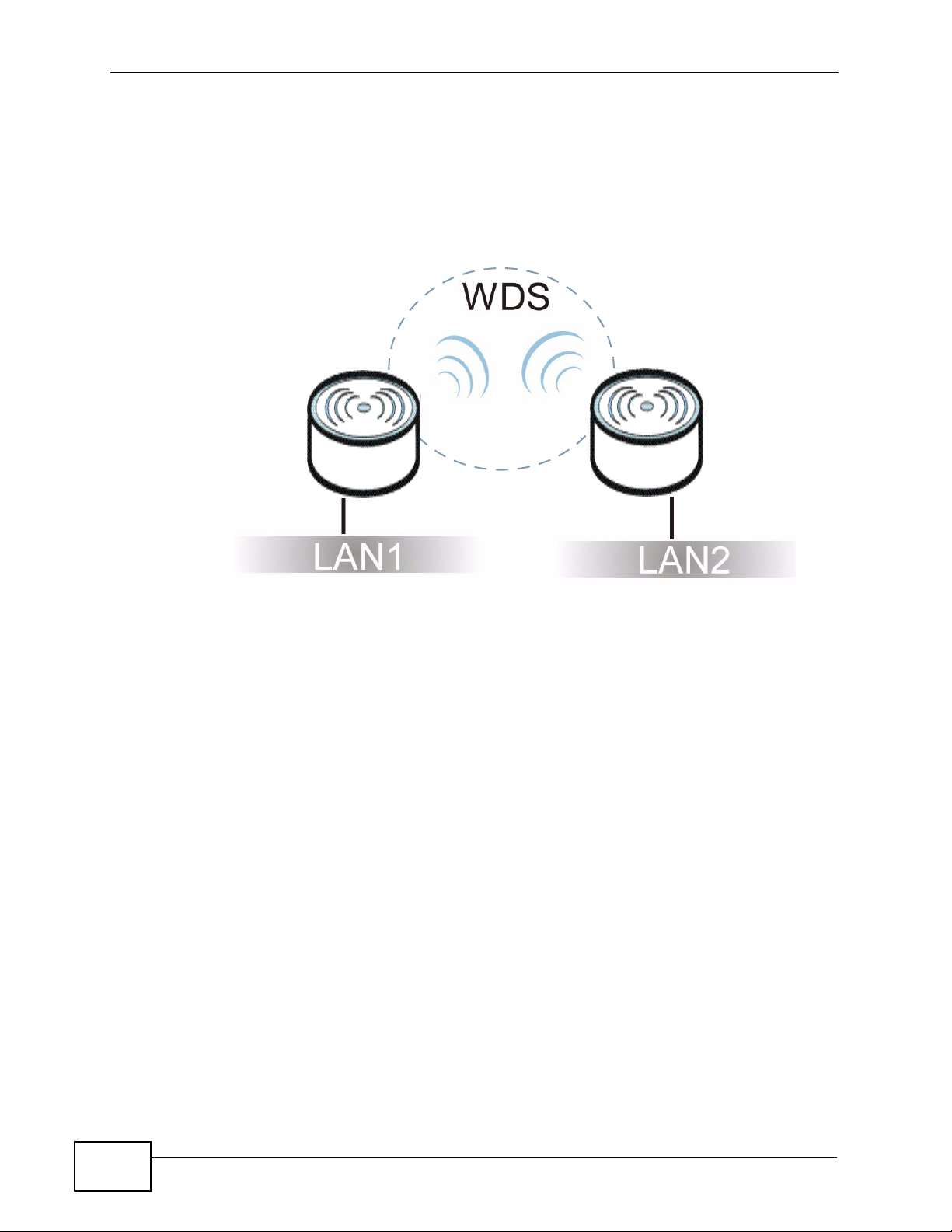
1.2.1.1 Bridge / Repeater Mode Example
In the example below, when both NWA3000-N series APs are in Bridge/Repeater
mode, they form a WDS (Wireless Distribution System) allowing the computers in
LAN 1 to connect to the computers in LAN 2.
Figure 3 Bridging Example
Be careful to avoid bridge loops when you enable bridging in the NW A3000-N
series AP. Bridge loops cause broadcast traffic to circle the network endlessly,
resulting in possible throughput degradation and disruption of communications.
The following examples show two network topologies that can lead to this
problem:
20
NWA3000-N Series User’s Guide
Page 21
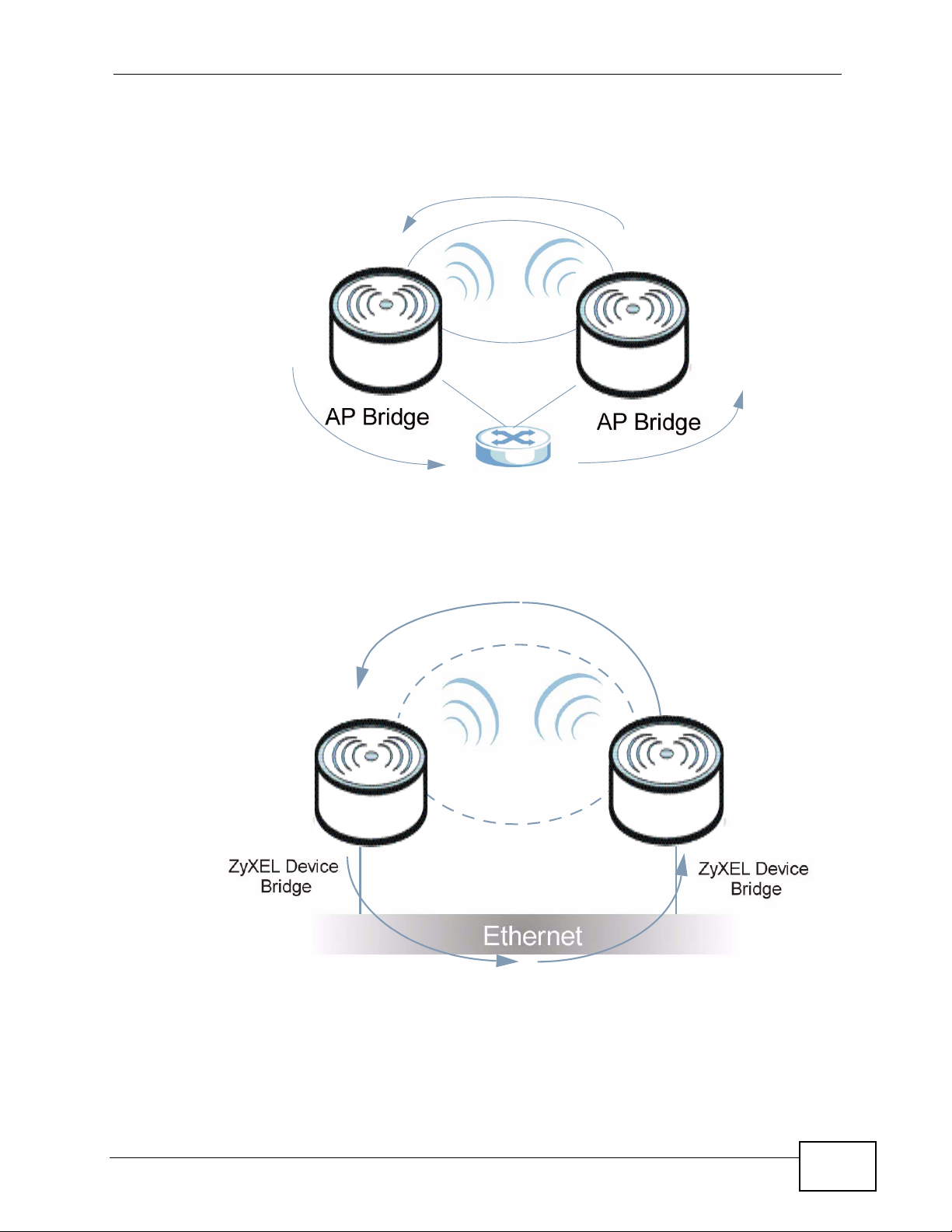
Chapter 1 Introduction
• If two or more NWA3000-N series APs (in bridge mode) are connected to the
same hub.
Figure 4 Bridge Loop: Two Bridges Connected to Hub
• If your NWA3000-N series AP (in bridge mode) is connected to a wired LAN
while communicating with another wireless bridge that is also connected to the
same wired LAN.
Figure 5 Bridge Loop: Bridge Connected to Wired LAN
To prevent bridge loops, ensure that you enable Spanning Tree Protocol (STP) in
the Wireless screen or your NW A3000-N series AP is not set to bridge mode while
connected to both wired and wireless segments of the same LAN.
NWA3000-N Series User’s Guide
21
Page 22
Chapter 1 Introduction
1.2.2 AP + Bridge
In AP + Bridge mode, the NWA3000-N series AP supports both AP and bridge
connection at the same time.
In the figure below, A and B use X as an AP to access the wired network, while X
and Y communicate in bridge mode.
When the NWA3000-N series AP is in AP + Bridge mode, security between APs
(WDS) is independent of the se cu ri ty be tween the wireless stations and the AP. If
you do not enable WDS security, tr affi c between APs is not encrypted. When WDS
security is enabled, both APs must use the same pre-shared key.
Unless specified, the term “security settings” refers to the traffic between the
wireless stations and the NWA3000-N series AP.
Figure 6 AP + Bridge Application
A
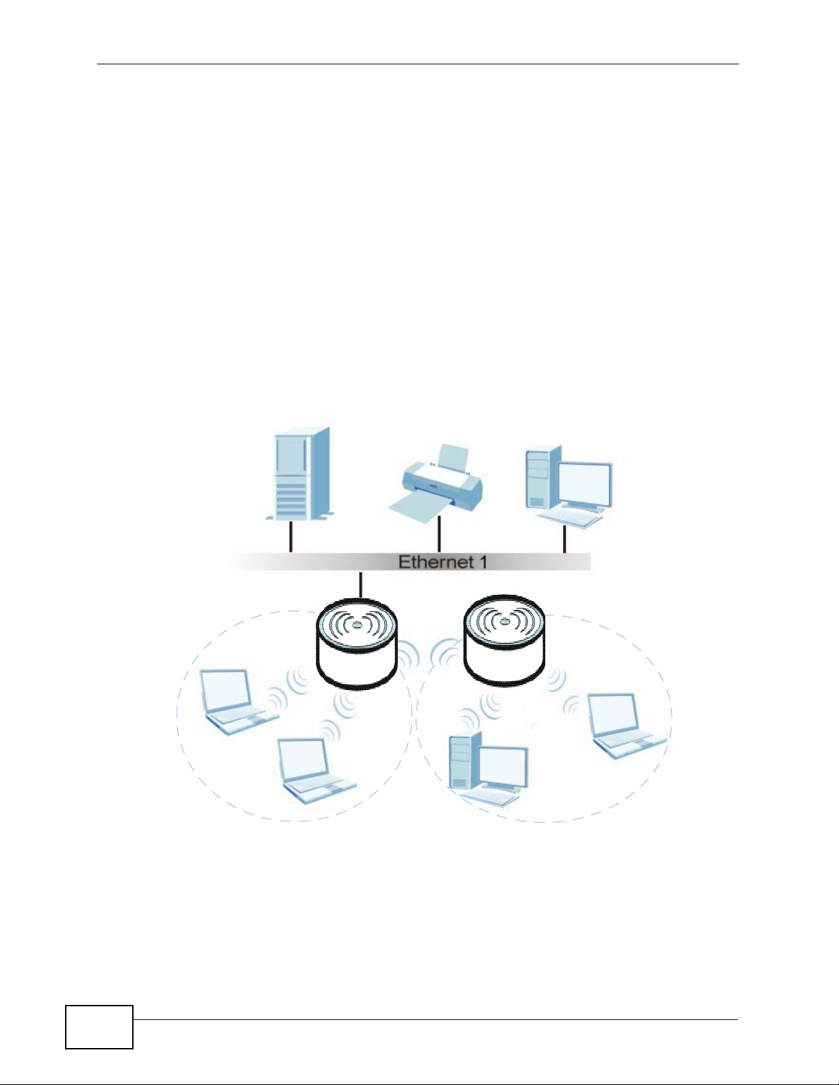
1.2.3 MBSSID
A Basic Service Set (BSS) is the set of devices forming a single wireless network
(usually an access point and one or more wireless clients). The Service Set
IDentifier (SSID) is the name of a BSS. In Multiple BSS (MBSSID) mode, the
22
Y
X
B
NWA3000-N Series User’s Guide
Page 23

NWA3000-N series AP provides multiple virtual APs, each forming its own BSS and
using its own individual SSID profile.
You can assign different wireless and security settings to each SSID profile. This
allows you to compartmentalize groups of users, set v arying access privileges, and
prioritize network traffic to and from certain BSSs.
To the wireless clients in the network, each SSID appears to be a different access
point. As in any wireless network, clients can associate only with the SSIDs for
which they have the correct security settings.
See Section 4.1 on page 55 for an example of using MBSS.
1.3 Management Mode
One NWA3000-N series AP uses Control And Provisioni ng of Wireless Access Points
(CAPWAP, see RFC 5415) to allow one AP to configure and manage up to 24
others. This centralized management can greatly reduce the effort of setting up
and maintaining multiple devices.
Chapter 1 Introduction
An NWA3000-N series AP in this group (ZLD-based models) can manage other APs
in this group
• NWA3160-N
• NWA3550-N
• NWA3560-N
It can also use legacy device information hyper-links to connect to the Web
Configurators of the following ZyNOS-based NWA-3000 series APs:
• NWA-3160
• NWA-3163
• NWA-3500
• NWA-3550
• NWA-3166
1
.
1. Not all of these models were available at the time of writing.
NWA3000-N Series User’s Guide
23
Page 24
Chapter 1 Introduction
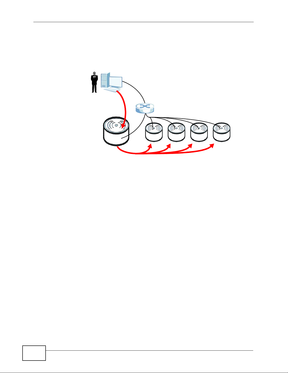
The following figure illustrates a CAPWAP wireless network. The user (U)
configures the controller AP (C), which then automatically updates the
configurations of the managed APs (M1 ~ M4).
Figure 7 CAPWAP Network Example
U
C
M1 M2 M3 M4
1.4 Ways to Manage the NWA3000-N series AP
You can use the following ways to manage the NWA3000-N series AP.
Web Configurator
The Web Configurator allows easy NWA3000-N series AP setup and management
using an Internet browser. This User’s Guide provides information about the Web
Configurator.
Command-Line Interface (CLI)
The CLI allows you to use text-based commands to configure the NWA3000-N
series AP. You can access it using remote management (for example, SSH or
Telnet) or via the console port. See the Command Reference Guide for more
information.
24
NWA3000-N Series User’s Guide
Page 25

Chapter 1 Introduction
Console Port
You can use the console port to manage the NWA3000-N series AP using CLI
commands. See the Command Reference Guide for more information about the
CLI. The default settings for the console port are as follows.
Table 1 Console Port Default Settings
SETTING VALUE
Speed 115200 bps
Data Bits 8
Parity None
Stop Bit 1
Flow Control Off
File Transfer Protocol (FTP)
This protocol can be used for firmware upgrades and configuration backup and
restore.
Simple Network Management Protocol (SNMP)
The NWA3000-N series AP can be monitored by an SNMP manager. See the SNMP
chapter in this User’s Guide.
Controller
Set one NWA3000-N series AP to be a controller and set other NWA3000-N series
APs to be managed by it.
1.5 Good Habits for Managing the NWA3000-N series AP
Do the following things regularly to make the NWA3000-N series AP more secure
and to manage it more effectively.
• Change the password often. Use a password that’s not easy to guess and that
consists of different types of characters, such as numbers and letters.
• Write down the password and put it in a safe place.
NWA3000-N Series User’s Guide
25
Page 26

Chapter 1 Introduction
• Back up the configuration (and make sure you know how to restore it).
Restoring an earlier working configuration may be useful if the device becomes
unstable or even crashes. If you forget y our password, you will hav e to reset the
NWA3000-N series AP to its factory default settings. If you back ed up an earl ier
configuration file, you won’t have to totally re-configure the NWA3000-N series
AP; you can simply restore your last configuration.
1.6 Hardware Connections
See your Quick Start Guide for information on making hardware connections.
26
NWA3000-N Series User’s Guide
Page 27
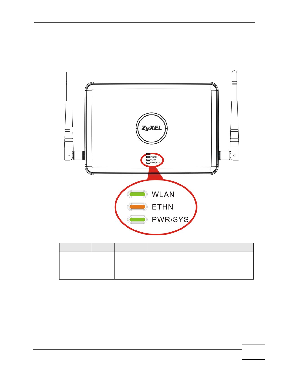
1.7 LEDs
The following are the LED descriptions for your NWA3000-N series AP.
Figure 8 LEDs
Chapter 1 Introduction
Table 2 LEDs
LABEL COLOR STATUS DESCRIPTION
WLAN Green
Off The wireless LAN is not active.
NWA3000-N Series User’s Guide
On The wireless LAN is active.
Blinking The wireless LAN is active, and transmitting or
receiving data.
27
Page 28

Chapter 1 Introduction
Table 2 LEDs (continued)
LABEL COLOR STATUS DESCRIPTION
ETHERNET Green On The NWA3000-N series AP has a 10/100 Mbps
POWER/SYS Green On The NWA3000-N series AP is receiving power
Ethernet connection.
Blinking The NWA3000-N series AP has a 10/100 Mbps
Ethernet connection and is sending or receiving
data.
Yellow On The NWA3000-N series AP has a 1000 Mbps
Ethernet connection.
Blinking The NWA3000-N series AP has a 1000 Mbps
Ethernet connection and is sending/receiving
data.
Off The NWA3000-N series AP does not have an
Ethernet connection.
and functioning properly.
Off The NWA3000-N series AP is not receiving
power.
Red Blinking Either
• If the LED blinks during the boot up process,
the system is starting up.
or
• If the LED blinks after the boot up process,
the system has failed.
Off The NWA3000-N series AP successfully boots
up.
28
NWA3000-N Series User’s Guide
Page 29
Chapter 1 Introduction
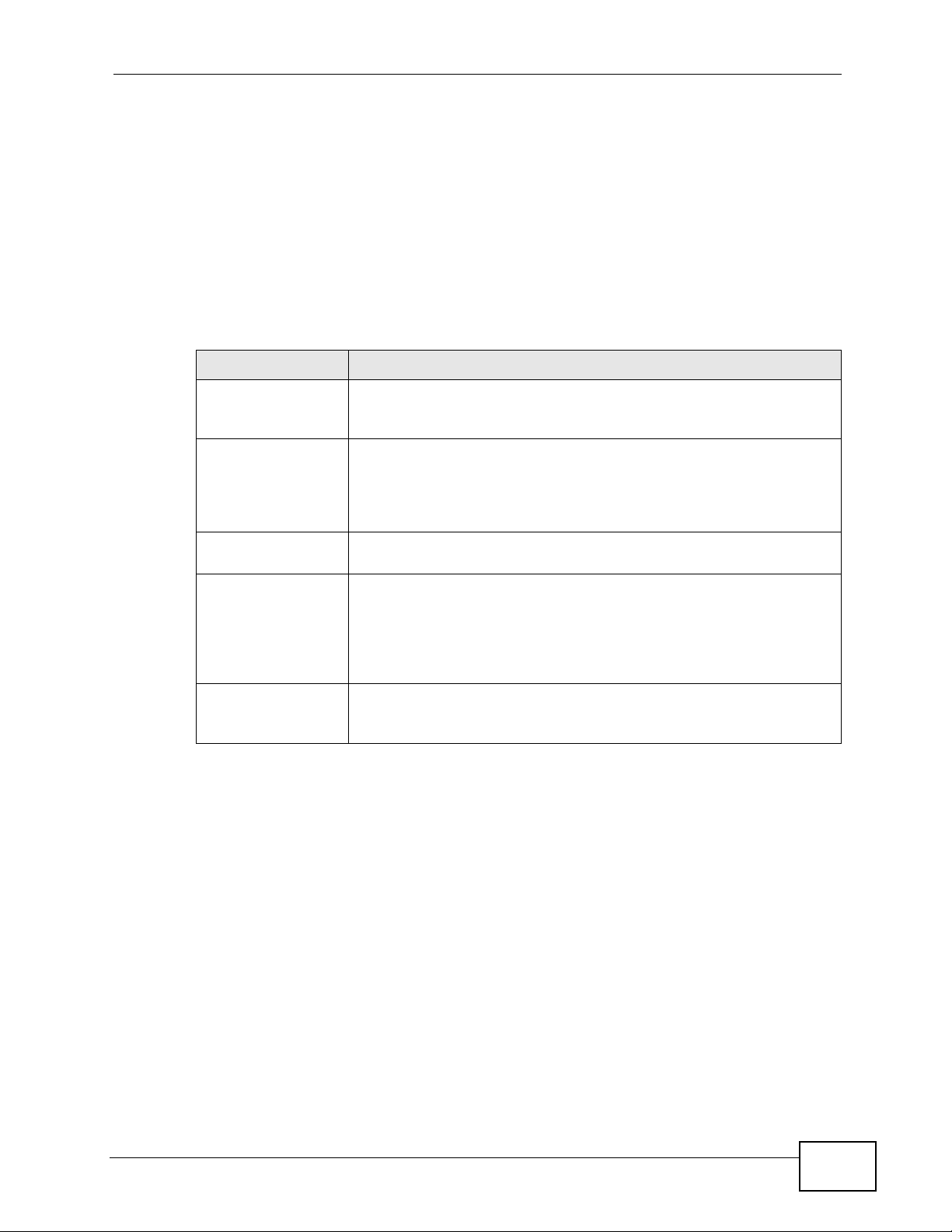
1.8 Starting and Stopping the NWA3000-N series AP
Here are some of the ways to start and stop the NWA3000-N series AP.
Always use Maintenance > Shutdown or the shutdown command
before you turn off the NW A3000-N series AP or remove the power . Not
doing so can cause the firmware to become corrupt.
Table 3 Starting and Stopping the NWA3000-N series AP
METHOD DESCRIPTION
Turning on the
power
Rebooting the
NWA3000-N series
AP
Using the RESET
button
Clicking
Maintenance >
Shutdown >
Shutdown or
using the shutdown
command
Disconnecting the
power
A cold start occurs when you turn on the power to the NWA3000-N
series AP. The NWA3000-N series AP powers up, checks the
hardware, and starts the system processes.
A warm start (without powering down and powering up again)
occurs when you use the Reboot button in the Reboot screen or
when you use the reboot command. The NWA3000-N series AP
writes all cached data to the local storage, stops the system
processes, and then does a warm start.
If you press the RESET button, the NWA3000-N series AP sets the
configuration to its default values and then reboots.
Clicking Maintenance > Shutdown > Shutdown or using the
shutdown command writes all cached data to the local storage and
stops the system processes. Wait for the device to shut down and
then manually turn off or remove the power. It does not turn off the
power.
Power off occurs when you turn off the power to the NWA3000-N
series AP. The NWA3000-N series AP simply turns off. It does not
stop the system processes or write cached data to local storage.
The NWA3000-N series AP does not stop or start the system processes when you
apply configuration files or run shell scripts although you may temporarily lose
access to network resources.
NWA3000-N Series User’s Guide
29
Page 30

Chapter 1 Introduction
30
NWA3000-N Series User’s Guide
Page 31

CHAPTER 2
The Web Configurator
2.1 Overview
The NWA3000-N series AP Web Configurator allows easy management using an
Internet browser.
In order to use the Web Configurator, you must:
• Use Internet Explorer 7.0 and later or Firefox 1.5 and later
• Allow pop-up windows
• Enable JavaScript (enabled by default)
• Enable Java permissions (enabled by default)
• Enable cookies
The recommended screen resolution is 1024 x 768 pixels and higher.
NWA3000-N Series User’s Guide
31
Page 32

Chapter 2 The Web Configurator
2.2 Access
1 Make sure your NWA3000-N series AP hardware is properly connected. See the
Quick Start Guide.
2 Browse to https://192.168.1.2. The Login screen appears.
3 Enter the user name (default: “admin”) and password (default: “1234”).
4 Click Login. If you logged in using the default user name and password, the
Update Admin Info screen appears. Otherwise, the dashboard appears.
This screen appears every time you log in usi ng the default user name and default
password. If you change the password for the default user account, this screen
does not appear anymore.
32
NWA3000-N Series User’s Guide
Page 33

2.3 The Main Screen
The Web Configurator’s main screen is divided into these parts:
Figure 9 The Web Configurator’s Main Screen
Chapter 2 The Web Configurator
A
B
• A - Title Bar
C
• B - Navigation Panel
• C - Main Window
NWA3000-N Series User’s Guide
33
Page 34

Chapter 2 The Web Configurator
2.3.1 Title Bar
The title bar provides some useful links that always appear over the screens
below, regardless of how deep into the Web Configurator you navigate.
Figure 10 Title Bar
The icons provide the following functions.
Table 4 Title Bar: Web Configurator Icons
LABEL DESCRIPTION
Logout Click this to log out of the Web Configurator.
Help Click this to open the help page for the current screen.
About Click this to display basic information about the NWA3000-N series AP.
Site Map Click this to see an overview of links to the Web Configurator screens.
Object
Reference
Console Click this to open the console in which you can use the command line
CLI Click this to open a popup window that displays the CLI commands sent
Click this to open a screen where you can check which configuration
items reference an object.
interface (CLI). See the NWA3000-N series AP CLI Reference Guide for
details.
by the Web Configurator.
2.3.2 Navigation Panel
Use the menu items on the navigation panel to open screens to configure
NWA3000-N series AP features. Click the arrow in the middle of the right edge of
the navigation panel to hide the navigation panel menus or dr ag it to resize them.
The following sections introduce the NWA3000-N series AP’ s navigation panel
menus and their screens.
Figure 11 Navigation Panel
34
NWA3000-N Series User’s Guide
Page 35

2.3.2.1 Dashboard
The dashboard displays general device information, system status, system
resource usage, and interface status in widgets that you can re-arrange to suit
your needs.
For details on the Dashboard’s features, see Chapter 5 on page 75.
2.3.2.2 Monitor Menu
The monitor menu screens display status and statistics information.
Table 5 Monitor Menu Screens Summary
FOLDER OR LINK TAB FUNCTION
LAN Status Displays general LAN interface information and packet
Wireless
AP Info Radio List Displays information about the radios of the connected
Station Info Displays information about the connected stations.
Rogue AP Displays information about suspected rogue APs.
Legacy Device
Info
Log View Log Displays log entries for the NWA3000-N series AP.
Chapter 2 The Web Configurator
statistics.
APs.
AP List Displays which APs are currently connected to the
NWA3000-N series AP. This is available when the
NWA3000-N series AP is in controller mode.
Use these screens to connect to legacy NWA3000-N
series AP 3000 APs. This is available when the
NWA3000-N series AP is in controller mode.
View AP
Log
Displays logs for connected APs.
2.3.2.3 Configuration Menu
Use the configuration menu screens to configure the NWA3000-N series AP’s
features.
Table 6 Configuration Menu Screens Summary
FOLDER OR
LINK
MGNT Mode Set whether the NWA3000-N series AP is
LAN Setting Manage the LAN Ethernet interface including VLAN
Wireless
NWA3000-N Series User’s Guide
TAB FUNCTION
controlling other NWA3000-N series APs, working
as a standalone AP, or being managed by another
NWA3000-N series AP.
settings.
35
Page 36

Chapter 2 The Web Configurator
Table 6 Configuration Menu Screens Summary (continued)
FOLDER OR
LINK
Controller Configure how the NWA3000-N series AP handles
AP
Management
MON Mode Configure how the NWA3000-N series AP monitors
Load
Balancing
DCS Configure dynamic wireless channel selection.
Device HA General Configure device HA global settings, and see the
Object
Users User Create and manage users.
AP Profile Radio Create and manage wireless radio settings files
MON Profile Create and manage rogue AP monitoring files that
Certificate My Certificates Create and manage the NWA3000-N series AP’s
System
Host Name Configure the system and domain name for the
Date/Time Configure the current date, time, and time zone in
Console
Speed
WWW Configure HTTP, HTTPS, and general
SSH Configure SSH server and SSH service settings.
TELNET Configure telnet server settings for the NWA3000-
TAB FUNCTION
APs that newly connect to the network. This is
available when the NWA3000-N series AP is in
controller mode.
Edit wireless AP information, remove APs, and
reboot them.
for rogue APs.
Configure load balancing for traffic moving to and
from wireless clients.
status of each interface monitored by device HA.
Device HA is available when the NWA3000-N series
AP is in controller mode.
Active-Passive
Mode
Setting Manage default settings for all users, general
SSID Create and manage wireless SSID, security, and
Trusted
Certificates
Configure active-passive mode device HA.
settings for user sessions, and rules to force user
authentication.
that can be associated with different APs.
MAC filtering settings files that can be associated
with different APs.
can be associated with different APs.
certificates.
Import and manage certificates from trusted
sources.
NWA3000-N series AP.
the NWA3000-N series AP.
Set the console speed.
authentication.
N series AP.
36
NWA3000-N Series User’s Guide
Page 37

Table 6 Configuration Menu Screens Summary (continued)
FOLDER OR
LINK
FTP Configure FTP server settings.
SNMP Configure SNMP communities and services.
Auth. Serve r Configure settings for the NWA3000-N series AP’s
Log & Report
Email Daily
Report
Log Setting Configure the system log, e-mail logs, and remote
TAB FUNCTION
2.3.2.4 Maintenance Menu
Use the maintenance menu screens to manage configuration and firmware files,
run diagnostics, and reboot or shut down the NWA3000-N series AP.
Table 7 Maintenance Menu Screens Summary
FOLDER OR
LINK
File Manager Configuration
Diagnostics Diagnostic Collect diagnostic information.
Reboot Restart the NWA3000-N series AP.
Shutdown Turn off the NWA3000-N series AP.
TAB FUNCTION
File
Firmware
Package
Shell Script Manage and run shell script files for the NWA3000-
Packet Capture Capture packets for analysis.
Wireless Frame
Capture
Chapter 2 The Web Configurator
built-in authentication server.
Configure where and how to send daily reports and
what reports to send.
syslog servers.
Manage and upload configuration files for the
NWA3000-N series AP.
View the current firmware version and to upload
firmware.
N series AP.
Capture wireless frames from APs for analysis.
NWA3000-N Series User’s Guide
37
Page 38

Chapter 2 The Web Configurator
2.3.3 Warning Messages
Warning messages, such as those resulting from misconfiguration, display in a
popup window.
Figure 12 Warning Message
2.3.4 Site Map
Click Site MAP to see an overview of links to the Web Configurator screens. Click
a screen’s link to go to that screen.
Figure 13 Site Map
2.3.5 Object Reference
Click Object Ref erence to open the Object Reference screen. Select the type of
object and the individual object and click Refresh to show which configuration
38
NWA3000-N Series User’s Guide
Page 39

Chapter 2 The Web Configurator
settings reference the object. The following example shows which configuration
settings reference the ldap-users user object (in this case the first firewall rule).
Figure 14 Object Reference
The fields vary with the type of object. The following table describes labels that
can appear in this screen.
Table 8 Object References
LABEL DESCRIPTION
Object Name This identifies the object for which the configuration settings that use it
are displayed. Click the object’s name to display the object’s
configuration screen in the main window.
# This field is a sequential value, and it is not associated with any entry.
Service This is the type of setting that references the selected object. Click a
service’s name to display the service’s configuration screen in the main
window.
Priority If it is applicable, this field lists the referencing configuration item’s
position in its list, otherwise N/A displays.
Name This field identifies the configuration item that references the object.
Description If the referencing configuration item has a description configured, it
displays here.
Refresh Click this to update the information in this screen.
Cancel Click Cancel to close the screen.
NWA3000-N Series User’s Guide
39
Page 40

Chapter 2 The Web Configurator
2.3.5.1 CLI Messages
Click CLI to look at the CLI commands sent by the Web Configurator. The se
commands appear in a popup window, such as the following.
Figure 15 CLI Messages
Click Clear to remove the currently displayed information.
Note: See the Command Reference Guide for information about the commands.
2.3.5.2 Console
The Console allows you to use CLI commands from directly within the Web
Configurator rather than havin g to use a separate terminal program. In add ition to
logging in directly to the NWA3000-N series AP’s CLI, you can also log into other
devices on the network through this Con sole. It uses SSH to establish a
connection.
40
NWA3000-N Series User’s Guide
Page 41

Chapter 2 The Web Configurator
Note: To view the functions in the Web Configurator user interface that correspond
directly to specific NWA3000-N series AP CLI commands, use the CLI
Messages window (see Section 2.3.5.1 on page 40) in tandem with this one.
Figure 16 Console
The following table describes the elements in this screen.
Table 9 Console
LABEL DESCRIPTION
Command Line
Enter commands for the device that you are currently logged into here.
If you are logged into the NWA3000-N series AP, see the CLI Reference
Guide for details on using the command line to configure it.
Device IP
Address
This is the IP address of the device that you are currently logged into.
Logged-In User
This displays the username of the account currently logged into the
NWA3000-N series AP through the Console Window.
Note: You can log into the Web Configurator with a different account
than used to log into the NWA3000-N series AP through the
Console.
NWA3000-N Series User’s Guide
41
Page 42

Chapter 2 The Web Configurator
Table 9 Console (continued)
LABEL DESCRIPTION
Connection
Status
This displays the connection status of the account currently logged in.
If you are logged in and connected, then this displays ‘Connected’.
If you lose the connection, get disconnected, or logout, then this
displays ‘Not Connected’.
Tx/RX Activity
Monitor
This displays the current upload / download activity . The faster and more
frequently an LED flashes, the faster the data connection.
Before you use the Console, ensure that:
• Your web browser of choice allows pop-up windows from the IP addres s
assigned to your NWA3000-N series AP.
• Your web browser allows Java programs.
• You are using the latest version of the Java program (http://www.java.com).
To login in through the Console:
1 Click the Console button on the Web Configurator title bar.
2 Enter the IP address of the NWA3000-N series AP and click OK.
42
NWA3000-N Series User’s Guide
Page 43

Chapter 2 The Web Configurator
3 Next, enter the User Name of the account being used to log into your target
device and then click OK.
4 You may be prompted to authenticate your account password, depending on the
type of device that you are logging into. Enter the password and click OK.
5 If your login is successful, the command line appears and the status bar at the
bottom of the Console updates to reflect your connection state.
NWA3000-N Series User’s Guide
43
Page 44

Chapter 2 The Web Configurator
2.3.6 Tables and Lists
The Web Configurator tables and lists are quite flexible and provide several
options for how to display their entries.
2.3.6.1 Manipulating Table Display
Here are some of the ways you can manipulate the We b Configurator tables.
1 Click a column heading to sort the table’s entries according to that column’s
criteria.
2 Click the down arrow next to a column heading for more options about how to
display the entries. The options available vary depending on the type of fields in
the column. Here are some examples of what you can do:
• Sort in ascending alphabetical order
• Sort in descending (reverse) alphabetical order
• Select which columns to display
• Group entries by field
• Show entries in groups
• Filter by mathematical operators (<, >, or =) or searching for text.
44
NWA3000-N Series User’s Guide
Page 45

Chapter 2 The Web Configurator
3 Select a column heading cell’s right border and drag to re-size the column.
4 Select a column heading and drag and drop it to change the column order. A green
check mark displays next to the column’s title when you drag the column to a valid
new location.
5 Use the icons and fields at the bottom of the table to navigate to different pages of
entries and control how many entries display at a time.
NWA3000-N Series User’s Guide
45
Page 46

Chapter 2 The Web Configurator
2.3.6.2 Working with Table Entries
The tables have icons for working with table entries. A sample is shown next. You
can often use the [Shift] or [Ctrl] ke y t o sel e c t multiple entries to remove,
activate, or deactivate.
Table 10 Common Table Icons
Here are descriptions for the most common table icons.
Table 11 Common Table Icons
LABEL DESCRIPTION
Add Click this to create a new entry. For features where the entry’s
position in the numbered list is important (features where the
NWA3000-N series AP applies the table’s entries in order like the
firewall for example), you can select an entry and click Add to create
a new entry after the selected entry.
Edit Double-click an entry or select it and click Edit to open a screen
where you can modify the entry’s settings. In some tables you can
just click a table entry and edit it directly in the table. For those types
of tables small red triangles display for table entries with changes
that you have not yet applied.
Remove To remove an entry, select it and click Remove. The NWA3000-N
series AP confirms you want to remove it before doing so.
Activate To turn on an entry, select it and click Activate.
Inactivate To turn off an entry, select it and click Inactivate.
Object Reference Select an entry and click Object Reference to open a screen that
shows which settings use the entry.
Move To change an entry’s position in a numbered list, select it and click
Move to display a field to type a number for where you want to put
that entry and press [ENTER] to move the entry to the number that
you typed. For example, if you type 6, the entry you are moving
becomes number 6 and the previous entry 6 (if there is one) gets
pushed up (or down) one.
46
NWA3000-N Series User’s Guide
Page 47

2.3.6.3 Working with Lists
When a list of available entries displays next to a list of selected entries, you can
often just double-click an entry to move it from one list to the other. In some lists
you can also use the [Shift] or [Ctrl] key to select multiple entries, and then use
the arrow button to move them to the other list.
Figure 17 Working with Lists
Chapter 2 The Web Configurator
NWA3000-N Series User’s Guide
47
Page 48

Chapter 2 The Web Configurator
48
NWA3000-N Series User’s Guide
Page 49

CHAPTER 3
Configuration Basics
3.1 Overview
This section provides information to help you configure the NWA3000-N series AP
effectively. Some of it is helpful when you are just getting started. Some of it is
provided for your reference when you configure various features in the NW A3000N series AP.
3.2 Object-based Configuration
The NWA3000-N series AP stores information or settings as objects. Y ou use these
objects to configure many of the NWA3000-N series AP’s features and settings.
Once you configure an object, you can reuse it in configuring other features.
When you change an object’s settings, the NWA3000-N series AP automatically
updates all the settings or rules that use the object. For example, if you create a
local certificate object, you can have HTTPS , FTP, SSH, and other settings use it. If
you modify the local certificate object, all the HT TPS, FTP, SSH, and other settings
that are linked to that object automatically apply the updated settings.
You can use the Configuration > Objects screens to create objects before you
configure features that use them. If you are in a screen that uses objects, you can
also usually select Create new Object to be able to configure a new object.
Use the Object Reference screen to see what objects are configured and which
configuration settings reference specific objects.
3.3 Feature Configuration Overview
This section provides information about configuring the main features in the
NWA3000-N series AP. The features are listed in the same sequence as the menu
item(s) in the Web Configur ator. Each feature description is organized as shown
below.
NWA3000-N Series User’s Guide
49
Page 50

Chapter 3 Configuration Basics
3.3.1 Feature
This provides a brief description. See the appropriate chapter(s) in this User’s
Guide for more information about any feature.
MENU ITEM(S)
PREREQUISITES
WHERE USED
This shows you the sequence of menu items and tabs you should click
to find the main screen(s) for this feature. See the web help or the
related User’s Guide chapter for information about each screen.
These are other features you should configure before you configure
the main screen(s) for this feature.
If you did not configure one of the prerequisites first, you can often
select an option to create a new object. After you create the object
you return to the main screen to finish configuring the feature.
You may not have to configure everything in the list of prerequisites.
For example, you do not have to create a schedule for a policy route
unless time is one of the criterion.
There are two uses for this.
These are other features you should usually configure or check right
after you configure the main screen(s) for this feature.
Note: PREQUISITES or WHERE USED does not appear if there are no prerequisites
or references in other features to this one. For example, no other features
reference AP management entries, so there is no WHERE USED entry.
3.3.2 MGNT Mode
Use this screen to set the NWA3000-N series AP to control other NWA3000-N
series APs, work as a standalone AP, or be managed by another NWA3000-N
series AP.
MENU ITEM(S)
3.3.3 LAN Setting
Use this screen to configure the LAN Ethernet interface including VLAN settings.
MENU ITEM(S)
You have to delete the references to this feature before you can delete
any settings.
Configuration > MGNT Mode.
Configuration > LAN Setting.
3.3.4 Wireless
Use these screens to manage your wireless Access Points.
MENU ITEM(S)
50
Configuration > Wireless.
NWA3000-N Series User’s Guide
Page 51

Chapter 3 Configuration Basics
PREREQUISITES
3.3.5 Device HA
To increase network reliability, device HA lets a backup NWA3000-N series AP
automatically take over if a master NWA3000-N series AP fails. Device HA is
available when the NWA3000-N series AP is in controller mode.
MENU ITEM(S)
PREREQUISITES
3.4 Objects
Objects store information and are referenced by other features. If you update this
information in response to changes, the NWA3000-N series AP automatically
propagates the change through the features that use the object. Select an object
(such as a user) and then click Object Reference at the top of the list box where
the object appears in order to display basic information about it.
Radio profiles, SSID profiles, and security profiles
Configuration > Device HA
Interfaces (with a static IP address), to-NWA3000-N series AP firewall
The following table introduces the objects. You can also use this table when you
want to delete an object because you have to delete references to the object first.
Table 12 Objects Overview
OBJECT WHERE USED
user See the User section on page 51 for details.
ap profile See the AP Profile section on page 52 for details.
mon profile See the MON Profile section on page 52 for details.
certificates WWW, SSH, FTP, controller
3.4.1 User
Use these screens to configure the NWA3000-N series AP’ s administr ator and user
accounts. The NWA3000-N series AP provides the following user types.
Table 13 User Types
TYPE ABILITIES
admin Change NWA3000-N series AP configuration (web, CLI)
limited-admin Look at NWA3000-N series AP configuration (web, CLI). Perform basic
user Access network services. Browse user-mode commands (CLI)
diagnostics (CLI)
NWA3000-N Series User’s Guide
51
Page 52

Chapter 3 Configuration Basics
3.4.2 AP Profile
Use these screens to configure preset profiles for the Access Points (APs)
connected to your NWA3000-N series AP’ s wireless network.
Table 14 AP Profile Types
TYPE ABILITIES
Radio Create radio profiles for the APs on your network.
SSID Create SSID profiles for the APs on your network.
Security Create security profiles for the APs on your network.
MAC Filtering Create MAC filtering profiles for the APs on your network.
3.4.3 MON Profile
Use these screens to set up monitor mode configurations that allow your
connected APs to scan for other wireless devices in the vicinity.
Table 15 MON Profile Types
TYPE ABILITIES
Monitor Create monitor mode configurations that can be used by the APs to
periodically listen to a specified channel or number of channels for
other wireless devices broadcasting on the 802.11 frequencies.
3.5 System
This section introduces some of the management features in the NWA3000-N
series AP. Use Host Name to configure the system and domain name for the
NWA3000-N series AP. Use Date/Time to configure the current date, time, and
time zone in the NWA3000-N series AP. Use Console Speed to set the console
speed. Use Language to select a language for the Web Configurator screens.
3.5.1 WWW, SSH, TELNET, FTP, SNMP, and Auth. Server
Use these screens to set which services or protocols can be used to access the
NWA3000-N series AP.
MENU ITEM(S)
PREREQUISITES
Configuration > System > WWW, SSH, TELNET, FTP, SNMP,
Auth. Server
certificates (WWW, SSH, FTP)
52
NWA3000-N Series User’s Guide
Page 53

3.5.2 Logs and Reports
The NWA3000-N series AP provides a system log, offers two e-mail profiles to
which to send log messages, and sends information to four syslog servers. It can
also e-mail you statistical reports on a daily basis.
Chapter 3 Configuration Basics
MENU ITEM(S)
3.5.3 File Manager
Use these screens to upload, download, delete, or run scripts of CLI commands.
You can manage:
• Configuration files. Use configuration files to back up and restore the complete
configuration of the NWA3000-N series AP. You can store multiple configuration
files in the NWA3000-N series AP and switch between them without restarting.
• Shell scripts. Use shell scripts to run a series of CLI commands. These are useful
for large, repetitive configuration changes and for troubleshooting.
You can edit configuration files and shell scripts in any text editor.
MENU ITEM(S)
3.5.4 Diagnostics
The NWA3000-N series AP can generate a file containing the NWA3000-N series
AP’s configuration and diagnostic information. It can also capture packets going
through the NWA3000-N series AP’ s interfaces so you can analyze them to ident ify
network problems
Configuration > Log & Report
Maintenance > File Manager
MENU ITEM(S)
3.5.5 Shutdown
Use this to shutdown the device in preparation for disconnecting the power.
Always use Maintenance > Shutdown > Shut down or the shutdown
command before you turn off the NWA3000-N series AP or remove the
power. Not doing so can cause the firmware to become corrupt.
MENU ITEM(S)
NWA3000-N Series User’s Guide
Maintenance > Diagnostics
Maintenance > Shutdown
53
Page 54

Chapter 3 Configuration Basics
54
NWA3000-N Series User’s Guide
Page 55

CHAPTER 4
Tutorials
4.1 Sample Network Setup
This tutorial shows you how to use CAPWAP to have one NWA3000-N series AP
control other NWA3000-N series APs to create a wireless network that allows two
types of connections: staff and guest. Staff connections have full access to the
network, while guests are limited to Internet access (DNS, HTTP and HTTPS
services).
Figure 18 Tutorial Network Topology
C
A
A
A
Requirements: A DHCP server (A) with Option 138, an AD server, a switch (B)
that supports 802.1q, a Layer-3 routing device and a firewall (C).
Note: In this topology the firewall, such as a ZyWALL, controls what services traffic
from different VLANs can use.
Controller
B
Managed APs
NWA3000-N Series User’s Guide
55
Page 56

Chapter 4 Tutorials
The following VLAN settings are used in this tutorial:
Table 16 Tutorial Topology Summary
VLAN VLAN ID IP ADDRESS
Management 99 10.10.99.10/24
Staff 101 10.1.101.254/24
Guest 102 10.1.102.254/24
Figure 19 Tutorial Guest VLAN Example
vlan 102
Controller
vlan 102
In this example, the guest VLAN (102) can only access the Internet while the
staff VLAN (101) has access to all aspects of the network.
4.1.1 Set the Management Modes
Use this section to set the management modes for the controller and managed
APs.
Managed APs
56
NWA3000-N Series User’s Guide
Page 57

4.1.1.1 Controller
1 Use the Configuration > MGNT MODE screen to set the NWA3000-N series AP
to controller mode.
2 The NWA3000-N series AP resets to its default settings for the controller mode
including the IP address of 192.168.1.2 and restarts. W ait a short while before you
attempt to log in again.
4.1.1.2 Managed APs
Chapter 4 Tutorials
1 Log into the other NWA3000-N series APs and use the Configuration > MGNT
MODE screen to set them to be the managed APs using the Auto IP address
option so they obtain the controller’s IP address from the DHCP server.
2 Now you can no longer log into the web configurator of the managed NW A300 0-N
series APs; you must manage the NWA3000-N series AP through the controller AP
on your network.
4.1.2 Set the LAN IP Address and Management VLAN (vlan99)
This section shows you how to set up the LAN IP address and the VLAN for
managing the controller. This is only for network administrators to manage the
controller.
NWA3000-N Series User’s Guide
57
Page 58

Chapter 4 Tutorials
1 Open the controller’s Configuration > LAN Setting screen.
• IP Address: Enter 10.10.99.10.
• Subnet Mask: Enter 255.255.255.0.
• Gateway: Enter 10.10.99.10.
• Management VLAN ID: Enter ‘99’ as the VLAN ID tag.
•Click Apply to save these changes.
2 Configure your DHCP server with the controller’s IP address configured as option
138 so the managed NWA3000-N series APs can get the controller’s IP address
from it. See Chapter 7 on page 103 for details.
4.1.3 Set Up Wireless User Authentication
This section shows you how to set up the controller’s internal RADIUS server and
user accounts.
Note: If you did not replace the factory default certificate with one that uses your
NWA3000-N series AP's MAC address when you first logged into the
NWA3000-N series AP, do it now in the Object > Certificate > My Certificates
screen.
58
NWA3000-N Series User’s Guide
Page 59

Chapter 4 Tutorials
1 Open the Configuration > System > Auth. Server screen. Turn on the
authentication server and select the certificate to use. Click Apply.
2 Open the Configuration > Object > User > User screen and click Add.
3 The Add A User window opens.
NWA3000-N Series User’s Guide
59
Page 60

Chapter 4 Tutorials
3a User Name: Enter ‘guest1’.
3b User Type: User
3c Password: Enter ‘guest1’, and re-enter it in the Retype field to confirm.
3d Click OK to save these settings.
4 Repeat steps 2 and 3 to create accounts for the staff members.
4.1.4 Create the AP Profiles (staff, guest)
This section shows you how to configure the Access Point (AP) profiles that wil l be
used by your APs once they are connected to the network. You will first create a
security profile and an SSID profile for staff access, then you will create a second
pair for guest access. Finally, you will associate them with a radio profile which is
applied to your AP’s r adio transmitter.
1 Open the Configuration > Object > AP Profile > SSID > Security List screen
and then click the Add button.
60
NWA3000-N Series User’s Guide
Page 61

2 The Add Security Profile window opens.
Chapter 4 Tutorials
2a Profile Name: Enter wap2.
2b Security Mode: Select wpa2 from the list of available wireless security
encryption methods.
2c Under Security Mode, select 802.1X then set the Radius Server Type to
Internal.
2d Click OK.
3 Next, open the Configuration > Object > AP Profile > SSID > SSID List
screen and click the Add button.
NWA3000-N Series User’s Guide
61
Page 62

Chapter 4 Tutorials
4 The Add SSID Profile window opens.
4a Profile Name: Enter ‘staff’.
4b SSID: Enter ‘staff’. This is the wireless network name that appears when
wireless clients are looking for networks to join.
4c Security Profile: Select wpa2 from the list. This is the security pr of il e
created in step 2.
4d QoS: Select WMM.
4e VLAN ID: Enter ‘101’.
4f Turn on intra-BSS traffic blocking.
4g Click OK to save these settings.
5 Repeat steps 3 and 4 to create the guest SSID profile with the same settings
except ‘guest’ as the profile name and SSID and 102 for the VLAN ID.
6 Open the Configuration > Object> AP Profile > Radio screen and then
double-click the default entry.
62
NWA3000-N Series User’s Guide
Page 63

7 The Edit Radio Profile window opens.
7a Activate: Select this to make the radio profile active.
Chapter 4 Tutorials
7b MBSSID Settings: Select an entry to change it to a drop-down list. Set #1,
to the staff SSID profile and #2 to the guest SSID profile. These are the two
profiles you created in steps 3 to 5 of this procedure.
7c Click OK to save these settings.
4.2 Rogue AP Detection
Rogue APs are wireless access points interacting with the network managed b y the
NWA3000-N series AP but which are not under the control of the network
administrator. In short, they are a security risk because they circumvent network
security policy. AP detection only works when at least 1 AP is configured for
Monitor mode.
The following are some suggestions on monitor AP placement:
• Neighboring companies that both support wireless network. If you can detect
your neighbor’s APs and you know they are ‘friendly’, you can add them to the
friendly exception list.
• Reception areas. If a reception area has a high volume of visitor traffic, it might
be useful to see if anyone is setting up their wireless device as an AP.
• High security areas. An AP set to Monitor mode will let you see if any one sets up
an unauthorized AP that could potentially compromise your security.
NWA3000-N Series User’s Guide
63
Page 64

Chapter 4 Tutorials
In this example, an employee illicitly connects his own AP (RG) to the network
that the NWA3000-N series AP manages. While not necessarily a malicious act, it
can nonetheless have severe security consequences on the network.
Figure 20 Rogue AP Example A
64
NWA3000-N Series User’s Guide
Page 65

Chapter 4 Tutorials
Here, an attacker sets up a rogue AP (RG) outside the network, which he uses in
an attempt to mimic an NWA3000-N series AP-controlled S SID in order to capture
passwords and other information when authorized wireless clients mistakenly
connect to it.
Figure 21 Rogue AP Example B
This tutorial shows you how to detect rogue APs on your network:
1 Click Configuration > Object > MON Profile to open the MON Profile screen
and click the Add button.
NWA3000-N Series User’s Guide
65
Page 66

Chapter 4 Tutorials
2 Click the Add button.
When the Add Mon Profile window opens, configure the following:
Activate: Select this to allow your monitor APs to use this profile.
Profile Name: For the purposes of this tutorial set this to ‘Monitor01’.
Channel Dwell Time: Leave this as the default 100 milliseconds. This field is the
number of milliseconds that the monitor AP scans each channel before moving on
to the next.
Scan Channel Mode: Set this to auto to automatically scan channels in the area.
3 Click OK to save your changes.
4 Next, click Configuration > Wireless > AP Management.
66
NWA3000-N Series User’s Guide
Page 67

5 Select an AP and click Edit.
When the Edit AP List window opens, configur e the following:
Chapter 4 Tutorials
Radio 1 OP Mode: Set this to MON Mode to turn the AP into a rogue AP
monitoring device.
Radio 1 Profile: Select your newly created ‘Monitor01’ profile from the list.
6 Click OK to save your changes.
See also: Chapter 6 on page 83 and Chapter 13 on page 165.
4.2.1 Rogue AP Containment
When the NWA3000-N series AP discovers a rogue AP within its broadcast radius,
it can react in one of two ways: If the rogue AP is connected directly to the
network (such as plugged into a switch downstream of the NWA3000-N series AP),
then the network administrator must manually disconnect it. The NWA3000-N
series AP does not allow the isolation of a rogue AP connected directly to the
network.
However, if a rogue AP independent of the NWA3000-N series AP mimics a
legitimate one, then the NWA3000-N series AP can interfere with it by
NWA3000-N Series User’s Guide
67
Page 68

Chapter 4 Tutorials
broadcasting dummy packets so that it cannot makes connections with employee
clients and capture data from them.
Figure 22 Containing a Rogue AP
This tutorial shows you how to quarantine a rogue AP on your network:
1 Click Configuration > Wireless > MON Mode.
68
NWA3000-N Series User’s Guide
Page 69

Chapter 4 Tutorials
2 Click the Add button.
When the Edit Rogue/Friendly AP List opens, paste the MAC address copied
from the other screen in the corresponding field, set its Role as Rogue AP and
then click OK to save your changes.
3 The new rogue AP appears in the Rogue/Friendly AP List.
Select it, then click the Containment button to quarantine it away from the rest
of the network.
4.3 Load Balancing
When your AP becomes overl oaded, there are two basic responses it can tak e. The
first one is to “delay” a client connection by withholding the connection until the
data transfer throughput is lowered or the client connection is picked up by
another AP. (If the client isn’t picked up after a set period of time, the AP allows it
to connect regardless.) The second response is to kick the connections until the AP
is no longer considered overloaded. Both of these tactics are known as ‘load
balancing’.
This tutorial shows you how to configure the NWA3000-N series AP’s load
balancing feature.
NWA3000-N Series User’s Guide
69
Page 70

Chapter 4 Tutorials
1 Click Configuration > Wireless > Load Balancing.
2 Select Enable Load Balancing to turn on this feature.
3 Set the Mode. If you choose By Station Number, then enter the Max Station
Number in the available field. This balanc es network tr affic based on the number
of specified stations downstream of the NWA3000-N series AP. If you choose By
Traffic Level, then enter the traffic threshold at which the NWA3000- N series AP
starts balancing connected stations.
4 Select Disassociate station when overloaded to disconnect stations when the
load balancing threshold is crossed. The stations are first disconnected based on
how long they have been idle, then secondly based on the weakness of their
connection signal strength.
5 Click Apply to save your changes.
See also: Chapter 9 on page 111.
4.4 Dynamic Channel Selection
Dynamic Channel Selection (DCS) is a feature that allows an AP to automatically
select the radio channel upon which it broadcasts by scanning the area around it
and determining what channels are currently being used by other devices.
When numerous APs broadcast within a given area, they introduce the possibility
of heightened radio interference, especially if some or all of them are broadcasting
on the same radio channel. This can make accessing the network potentially
rather difficult for the stations connected to them. If the interference becomes too
great, then the network administrator must open his AP configuration options and
manually change the channel to one that no other AP is using (or at least a
channel that has a lower level of interference) in order to give the connected
stations a minimum degree of channel interference.
70
NWA3000-N Series User’s Guide
Page 71

1 Click Configuration > Wireless > DCS.
Chapter 4 Tutorials
2 Select Enable Dynamic Channel Selection to turn on this feature.
3 Set the DCS Time Interval. This is how often the NWA3000-N series AP surveys
the other APs within its broadcast radius. If you place your APs in an area with a
large number of competing APs, set this number lower to ensure that your device
can adjust quickly changing conditions.
4 Select DCS Sensitivity Level. This is how sensitive the APs on your network are
to other channels. Generally, as long as the area in which your AP is located has
minimal interference from other devices you can set the DCS Sensitivity Level to
Low. This means that the AP has a very broad tolerance.
5 Select Enable DCS Client Aware. Select this so that the APs on your network do
not change channels as long as any wireless clients are connected to them. When
they must change channels, they will wait until all stations disconnect first.
6 Set the 2.4-GHz Channel Selection Method to auto.
7 Select a 2.4 GHz Channel Deployment scheme. Choose Three-Channel
Deployment to have the device rotate through 3 channels. Choose FourChannel Deployment to have the device rotate through 4 channels, if allowed.
8 Click Apply to save your changes.
See also: Chapter 9 on page 111.
NWA3000-N Series User’s Guide
71
Page 72

Chapter 4 Tutorials
72
NWA3000-N Series User’s Guide
Page 73

PART II
Technical Reference
73
Page 74

74
Page 75

CHAPTER 5
Dashboard
5.1 Overview
Use the Dashboard screens to check status information about the NWA3000-N
series AP.
5.1.1 What You Can Do in this Chapter
•The main Dashboard screen (Section 5.2 on page 76) displays the NW A3000-N
series AP’s general device information, system status, system resource usage,
and interface status. You can also displ ay other status screens for more
information.
NWA3000-N Series User’s Guide
75
Page 76

Chapter 5 Dashboard
5.2 Dashboard
This screen is the first thing you see when you log into the NW A3000-N series AP.
It also appears every time you click the Dashboard icon in the navigation panel.
The Dashboard displays general device information, system status, system
resource usage, and interface status in widgets that you can re-arrange to suit
your needs. You can also collapse, refresh, and close individual widgets.
Figure 23 Dashboard
A
B
C
D
E
76
The following table describes the labels in this screen.
Table 17 Dashboard
LABEL DESCRIPTION
Widget Settings
(A)
Up Arrow (B) Click this to collapse a widget.
Refresh Time
Setting (C)
Refresh Now (D) C lick this to update the widget’s information immediately.
Close Widget (E) Click this to close the widget. Use Widget Setting to re-open it.
Device
Information
Use this link to re-open closed widgets. Widgets that are already open
appear grayed out.
Set the interval for refreshing the information displayed in the widget.
NWA3000-N Series User’s Guide
Page 77

Chapter 5 Dashboard
Table 17 Dashboard (continued)
LABEL DESCRIPTION
System Name This field displays the name used to identify the NWA3000-N series
AP on any network. Click the icon to open the screen where you can
change it.
Model Name This field displays the model name of this NWA3000-N series AP.
Serial Number This field displays the serial number of this NWA3000-N series AP.
MAC Address
Range
Firmware
Version
System
Resources
CPU Usage This field displays what percentage of the NWA3000-N series AP’s
Memory Usage This field displays what percentage of the NWA3000-N series AP’s
Flash Usage This field displays what percentage of the NWA3000-N series AP’s
AP Information This shows a summary of connected wireless Access Points (APs).
All AP This section displays a summary for all connected wireless APs when
Online
Management
AP
Offline
Management
AP
UnManagement
AP
All Station This section displays a summary of connected stations when the
Station This displays the number of stations currently connected to the
All Sensed Device This sections displays a summary of all wireless devices detected by
Un-Classified APThis displays the number of detected unclassified APs.
This field displays the MAC addresses used by the NWA3000-N series
AP. Each physical port or wireless radio has one MAC address. The
first MAC address is assigned to the Ethernet LAN port, the second
MAC address is assigned to the first radio, and so on.
This field displays the version number and date of the firmware the
NWA3000-N series AP is currently running. Click the icon to open the
screen where you can upload firmware.
processing capability is currently being used. Hover your cursor over
this field to display the Show CPU Usage icon that takes you to a
chart of the NWA3000-N series AP’s recent CPU usage.
RAM is currently being used. Hover your cursor over this field to
display the Show Memory Usage icon that takes you to a chart of
the NWA3000-N series AP’s recent memory usage.
onboard flash memory is currently being used.
the NWA3000-N series AP is in controller mode.
This displays the number of currently connected managed APs.
This displays the number of currently offline managed APs.
This displays the number of non-managed APs.
NWA3000-N series AP is in controller mode.
network.
the network.
Rogue AP This displays the number of detected rogue APs.
Friendly AP This displays the number of detected friendly APs.
NWA3000-N Series User’s Guide
77
Page 78

Chapter 5 Dashboard
Table 17 Dashboard (continued)
LABEL DESCRIPTION
WDS Link Status This section displays information about the WDS settings when the
Radio This field displays which radio the NWA3000-N series AP is configured
Link ID This field displays the name of the bridge connection.
Peer MAC
Address
Security This field displays which type of security the NWA3000-N series AP is
Status This field displays the status of the connection to the peer device.
System Status
System
Uptime
Current Date/
Time
Current Login
User
Boot Status This field displays details about the NWA3000-N series AP’s startup
NWA3000-N series AP is in controller mode and configured to use
WDS.
to use for WDS.
This field displays the hardware address of the peer device.
using for WDS with this radio.
This field displays how long the NWA3000-N series AP has been
running since it last restarted or was turned on.
This field displays the current date and time in the NWA3000-N series
AP. The format is yyyy-mm-dd hh:mm:ss.
This field displays the user name used to log in to the current session,
the amount of reauthentication time remaining, and the amount of
lease time remaining.
state.
Management
Mode
Interface Status
Summary
OK - The NWA3000-N series AP started up successfully.
Firmware update OK - A firmware update was successful.
Problematic configuration after firmware update - The
application of the configuration failed after a firmware upgrade.
System default configuration - The NWA3000-N series AP
successfully applied the system default configuration. This occurs
when the NWA3000-N series AP starts for the first time or you
intentionally reset the NWA3000-N series AP to the system default
settings.
Fallback to lastgood configuration - The NWA3000-N series AP
was unable to apply the startup-config.conf configuration file and fell
back to the lastgood.conf configuration file.
Fallback to system default configuration - The NWA3000-N
series AP was unable to apply the lastgood.conf configuration file and
fell back to the system default configuration file (system-
default.conf).
Booting in progress - The NWA3000-N series AP is still applying the
system configuration.
This shows whether the NWA3000-N series AP is set to control other
NWA3000-N series APs, work as a stand alone AP, or be controlled by
another NWA3000-N series AP.
If an Ethernet interface does not have any physical ports associated
with it, its entry is displayed in light gray text. Click the Detail icon to
go to a (more detailed) summary screen of interface statistics.
78
NWA3000-N Series User’s Guide
Page 79

Chapter 5 Dashboard
Table 17 Dashboard (continued)
LABEL DESCRIPTION
Name This field displays the name of each interface.
Status This field displays the current status of each interface. The possible
values depend on what type of interface it is.
Inactive - The Ethernet interface is disabled.
Down - The Ethernet interface is enabled but not connected.
Speed / Duplex - The Ethernet interface is enabled and connected.
This field displays the port speed and duplex setting (Full or Half).
VID This field displays the VLAN ID to which the interface belongs.
HA Status This displays when the NWA3000-N series AP is in controller mode.
This field displays the status of the interface in the virtual router.
Active - This interface is the master interface in the virtual router.
Stand-By - This interface is a backup interface in the virtual router.
Fault - This VRRP group is not functioning in the virtual router right
now. For example, this might happen if the interface is down.
n/a - Device HA is not active on the interface.
IP Addr/
Netmask
IP Assignment This field displays how the interface gets its IP address.
Action Use this field to get or to update the IP address for the interface.
T op 5 Station When the NWA3000-N series AP is in controller mode this displays the
# This field displays the rank of the station.
AP MAC This field displays the MAC address of the AP to which the station
Max. Station
Count
AP Description This displays the description of the AP to which the radio belongs.
WLAN Interface
Status Summary
Status This displays whether or not the WLAN interface is activated.
MAC Address This displays the MAC address of the radio.
This field displays the current IP address and subnet mask assigned
to the interface. If the IP address is 0.0.0.0, the interface is disabled
or did not receive an IP address and subnet mask via DHCP.
If this interface is a member of an active virtual router, this field
displays the IP address it is currently using. This is either the static IP
address of the interface (if it is the master) or the management IP
address (if it is a backup).
Static - This interface has a static IP address.
DHCP Client - This interface gets its IP address from a DHCP server.
Click Renew to send a new DHCP request to a DHCP server.
top 5 Access Points (AP) with the highest number of station (aka
wireless client) connections during the past 24 hours.
belongs.
This field displays the maximum number of wireless clients that have
connected to this AP.
When the NWA3000-N series AP is in standalone mode this displays
status information for the WLAN interface.
NWA3000-N Series User’s Guide
79
Page 80

Chapter 5 Dashboard
Table 17 Dashboard (continued)
LABEL DESCRIPTION
Radio This indicates the radio number on the NWA3000-N series AP.
Band This indicates the wireless frequency band currently being used by
OP Mode This indicates the radio’s operating mode. Operating modes are AP
Channel This indicates the channel number the radio is using.
Station This displays the number of wireless clients connected to the
5.2.1 CPU Usage
Use this screen to look at a chart of the NWA3000-N series AP’ s recent CPU usage.
To access this screen, click CPU Usage in the dashboard.
Figure 24 Dashboard > CPU Usage
the radio.
(access point) or MON (monitor).
NWA3000-N series AP.
80
The following table describes the labels in this screen.
Table 18 Dashboard > CPU Usage
LABEL DESCRIPTION
% The y-axis represents the percentage of CPU usage.
time The x-axis shows the time period over which the CPU usage occurred
Refresh
Interval
Refresh Now Click this to update the information in the window right away.
Enter how often you want this window to be automatically updated.
NWA3000-N Series User’s Guide
Page 81

5.2.2 Memory Usage
Use this screen to look at a chart of the NWA3000-N series AP’s recent memory
(RAM) usage. To access this screen, click Memory Usage in the dashboard.
Figure 25 Dashboard > Memory Usage
Chapter 5 Dashboard
The following table describes the labels in this screen.
Table 19 Dashboard > Memory Usage
LABEL DESCRIPTION
The y-axis represents the percentage of RAM usage.
The x-axis shows the time period over which the RAM usage occurred
Refresh
Interval
Refresh Now Click this to update the information in the window right away.
Enter how often you want this window to be automatically updated.
NWA3000-N Series User’s Guide
81
Page 82

Chapter 5 Dashboard
82
NWA3000-N Series User’s Guide
Page 83

CHAPTER 6
Monitor
6.1 Overview
Use the Monitor screens to check status and statistics info rm at ion.
6.1.1 What You Can Do in this Chapter
•The LAN Status screen (Section 6.3 on page 84) displays general LAN interface
information and packet statistics.
•The LAN Status Graph screen (Section 6.3.1 on page 86) displays a line graph
of packet statistics for the NWA3000-N series AP’s physical LAN port.
•The AP List screen (Section 6.4 on page 87) displays which APs are currently
connected to the NWA3000-N series AP. This is available when the NWA3000-N
series AP is in controller mode.
•The Radio List screen (Section 6.5 on page 89) displays statistics about th e
wireless radio transmitters in each of the APs connected to the NWA3000-N
series AP.
•The Station Info screen (Section 6.6 on page 93) displays information about
suspected rogue APs.
•The Rogue AP screen (Section 6.7 on page 94) displays information about
suspected rogue APs.
•Use the Legacy Device screens (Section 6.8 on page 95) to connect to legacy
NWA3000-N series AP 3000 APs. This is available when the NWA3000-N series
AP is in controller mode.
•The View Log screen (Section 6.9 on page 96) displays the NWA3000-N series
AP’s current log messages. Y ou can change the way the log is displayed, y ou can
e-mail the log, and you can also clear the log in this screen.
•The View AP Log screen (Section 6.10 on page 100) displays the NWA3000-N
series AP’s current wireless AP log messages. This is available when the
NWA3000-N series AP is in controller mode.
6.2 What You Need to Know
The following terms and concepts may help as you read through the chapter.
NWA3000-N Series User’s Guide
83
Page 84

Chapter 6 Monitor
Rogue AP
Rogue APs are wireless access points operating in a network’s coverage area that
are not under the control of the network’s administrators, and can open up holes
in a network’s security. See Chapter 13 on page 165 for details.
Friendly AP
Friendly APs are other wireless access points that are detected in your network, as
well as any others that you know are not a threat (those from neighboring
networks, for example). See Chapter 13 on page 165 for details.
6.3 LAN Status
Use this screen to look at general LAN interface information and packet statistics.
To access this screen, click Monitor > LAN Status.
Figure 26 Monitor > LAN Status
The following table describes the labels in this screen.
Table 20 Monitor > LAN Status
LABEL DESCRIPTION
Poll Interval Enter how often you want this window to be updated automatically, and
click Set Interval.
Set Interval Click thi s to set the Poll Interval the screen uses.
Stop Click this to stop the window from updating automatically. You can start
it again by setting the Poll Interval and clicking Set Interval.
Interface
Summary
84
NWA3000-N Series User’s Guide
Page 85

Chapter 6 Monitor
Table 20 Monitor > LAN Status (continued)
LABEL DESCRIPTION
Name This field displays the name of the interface.
Status This field displays the current status of the interface:
Inactive - The Ethernet interface is disabled.
Down - The Ethernet interface is enabled but not connected.
Speed / Duplex - The Ethernet interface is enabled and connected.
This field displays the port speed and duplex setting (Full or Half).
HA Status This is available when the NWA3000-N series AP is in controller mode.
This field displays the status of the interface in the virtual router.
Active - This interface is the master interface in the virtual router.
Stand-By - This interface is a backup interface in the virtual router.
Fault - This VRRP group is not functioning in the virtual router right now.
For example, this might happen if the interface is down.
n/a - Device HA is not active on the interface.
VID This field displays the VLAN ID to which the interface belongs.
IP Addr/
Netmask
This field displays the current IP address and subnet mask assigned to
the interface. If the IP address and subnet mask are 0.0.0.0, the
interface is disabled or did not receive an IP address and subnet mask
via DHCP.
If this interface is a member of an active virtual router, this field displays
the IP address it is currently using. This is either the static IP address of
the interface (if it is the master) or the management IP address (if it is a
backup).
IP Assignment This field displays how the interface gets its IP address.
Static - This interface has a static IP address.
DHCP Client - This interface gets its IP address from a DHCP server.
Action Use this field to get or to update the IP address for the interface. Click
Renew to send a new DHCP request to a DHCP server . Click Connect to
try to connect the interface. If the interface cannot use one of these
ways to get or to update its IP address, this field displays n/a.
Port Statistics
Table
Switch to
Graphic View
Status This field displays the current status of the physical port.
TxPkts This field displays the number of packets transmitted from the
RxPkts This field displays the number of packets received by the NWA3000-N
Click this to display the port statistics as a line graph.
Down - The physical port is not connected.
Speed / Duplex - The physical port is connected. This field displays the
port speed and duplex setting (Full or Half).
NWA3000-N series AP on the physical port since it was last connected.
series AP on the physical port since it was last connected.
NWA3000-N Series User’s Guide
85
Page 86

Chapter 6 Monitor
Table 20 Monitor > LAN Status (continued)
LABEL DESCRIPTION
Collisions This field displays the number of collisions on the physical port since it
was last connected.
Tx This field displays the transmission speed, in bytes per second, on the
physical port in the one-second interval before the screen updated.
Rx This field displays the reception speed, in bytes per second, on the
physical port in the one-second interval before the screen updated.
Up Time This field displays how long the physical port has been connected.
System Up
Time
This field displays how long the NWA3000-N series AP has been running
since it last restarted or was turned on.
6.3.1 LAN Status Graph
Use the port statistics graph to look at a line graph of packet statistics for the
NWA3000-N series AP’s ph ysical LAN port. To view, in the LAN Status screen click
the Switch to Graphic View button.
Figure 27 Monitor > LAN Status > Switch to Graphic View
The following table describes the labels in this screen.
86
Table 21 Monitor > LAN Status > Switch to Graphic View
LABEL DESCRIPTION
Refresh
Interval
Refresh Now Click this to update the information in the window right away.
Enter how often you want this window to be automatically updated.
NWA3000-N Series User’s Guide
Page 87

Table 21 Monitor > LAN Status > Switch to Graphic View (continued)
LABEL DESCRIPTION
Switch to Grid
View
Kbps The y-axis represents the speed of transmission or reception.
time The x-axis shows the time period over which the transmission or
TX This line represents traffic transmitted from the NWA3000-N series AP
RX This line represents the traffic received by the NWA3000-N series AP on
Last Update This field displays the date and time the information in the window was
6.4 AP List
Chapter 6 Monitor
Click this to display the port statistics as a table.
reception occurred
on the physical port since it was last connected.
the physical port since it was last connected.
last updated.
Use this screen to view which APs are currently connected to the NWA3000-N
series AP. This is available when the NWA3000-N series AP is in controller mode.
To access this screen, click Monitor > Wireless > AP Information > AP List.
Figure 28 Monitor > Wireless > AP Information > AP List
NWA3000-N Series User’s Guide
87
Page 88

Chapter 6 Monitor
The following table describes the labels in this screen.
Table 22 Monitor > Wireless > AP Information > AP List
LABEL DESCRIPTION
Add to Mgnt AP
List
More
Information
# This is the AP’s index number in this list.
Status This visually displays the AP’s connection status with icons. For details
Registration This indicates whether the AP is registered with the managed AP list.
IP Address This displays the AP’s IP address.
MAC Address This displays the AP’s MAC address.
Model This displays the AP’s model number.
Mgmt. VLAN IDThis displays the number of the AP’s management VLAN.
When the NWA3000-N series AP is in controller mode, it lists the
compatible NWA3000-N series APs it detects in this screen. Select an
entry where the Status displays an AP icon with a question mark (?) and
click this button to have the NWA3000-N series AP manage it.
Click this to view a daily station count about the selected AP. The count
records station activity on the AP over a consecutive 24 hour period.
on the different Status states, see the next table.
Description This displays the AP’s associated description. The default description is
“AP-” + the AP’s MAC Address.
Station This displays the number of stations (aka wireless clients) associated
with the AP.
Refresh Click this to refresh the items displayed on this page.
The following table describes the icons in this screen.
Table 23 Monitor > Wireless > AP List Icons
LABEL DESCRIPTION
This is an AP that is not on the management list.
This is an AP that is on the management list and which is online.
This is an AP that is in the process of having its firmware updated.
This is an AP that is both on the management list and which is offline.
88
NWA3000-N Series User’s Guide
Page 89

6.4.1 Station Count of AP
Use this screen to look at station statistics for the connected AP. To access this
screen, click the More Information button in the AP List screen.
Figure 29 Monitor > System Status > AP List > More Information
Chapter 6 Monitor
The following table describes the labels in this screen.
Table 24 Monitor > System Status > AP List > More Information
LABEL DESCRIPTION
Station Count The y-axis represents the number of connected stations.
Time The x-axis shows the time over which a station was connected.
Last Update This field displays the date and time the information in the window was
last updated.
6.5 Radio List
Use this screen to view statistics for the NWA3000-N series AP’s wireless radio
transmitters when it is in standalone mode or the radios in each of the APs
NWA3000-N Series User’s Guide
89
Page 90

Chapter 6 Monitor
connected to the NWA3000-N series AP when it is in controller mode. To access
this screen, click Monitor > Wireless > AP Information > Radio List.
Figure 30 Monitor > Wireless > AP Information > Radio List (Controller Mode)
The following table describes the labels in this screen.
Table 25 Monitor > Wireless > AP Information > Radio List
LABEL DESCRIPTION
More
Information
# When the NWA3000-N series AP is in controller mode, this is the radio’s
Status When the NWA3000-N series AP is in standalone mode, this displays
Loading This indicates the AP’s load balance status.
AP Description This displays the description of the AP to which the radio belongs.
Model This displays the model of the AP to which the radio belongs.
MAC Address This displays the MAC address of the radio.
Radio This indicates the radio number on the AP to which it belongs.
OP Mode This indicates the radio’s operating mode. Operating modes are AP
Profile This indicates the profile name to which the radio belongs.
Frequency
Band
Channel ID This indicates the radio’s channel ID.
Station When the NWA3000-N series AP is in standalone mode, this displays the
Rx PKT This displays the total number of packets received by the radio.
Tx PKT This displays the total number of packets transmitted by the radio.
Rx FCS Error
Count
Tx Retry Count This indicates the number of times the radio has attempted to re-
Click this to view additional information about the selected radio’s
wireless traffic and station count. Information spans a 24 hour period.
index number in this list.
whether or not the WLAN interface is activated.
(access point) or MON (monitor).
This indicates the wireless frequency band currently being used by the
radio.
number of wireless clients connected to the NWA3000-N series AP.
This indicates the number of received packet errors accrued by the radio.
transmit packets.
90
NWA3000-N Series User’s Guide
Page 91

6.5.1 AP Mode Radio Information
This screen allows you to view a selected radio’s MBSSID details, wireless traffic
statistics and station count for the preceding 24 hours. To access this window,
click the More Information button in the Radio List Statistics screen.
Figure 31 Monitor > Wireless > AP Information > Radio List > More Information
Chapter 6 Monitor
NWA3000-N Series User’s Guide
91
Page 92

Chapter 6 Monitor
The following table describes the labels in this screen.
Table 26 Monitor > Wireless > AP Information > Radio List > More Information
LABEL DESCRIPTION
MBSSID Detail This list shows information about all the wireless clients that have
WDS Link
Detail
Traffic
Statistics
Station Count The y-axis represents the number of connected stations.
OK Click this to close this window.
Cancel Click this to close this window.
connected to the specified radio over the preceding 24 hours.
# This is the items sequential number in the list. It has no bearing on the
actual data in this list.
SSID Name This displays an SSID associated with this radio. There can be up to
eight maximum.
BSSID This displays a BSSID associated with this radio. The BSSID is tied to the
SSID.
Security
Mode
VLAN This displays the VLAN ID associated with the SSID.
Link ID This field displays the name of the bridge connection.
Peer MAC
Address
Status This field displays the status of the connection to the peer device.
Security
Mode
Link Up
Time
bps This axis represents the amount of data moved across this radio in
time This axis represents the amount of time over which the data moved
Time The x-axis shows the time over which a station was connected.
Last Update This field displays the date and time the information in the window was
This displays the security mode in which the SSID is operating.
When the NWA3000-N series AP is in standalone mode and you set the
wireless operating mode to AP+Bridge or Bridge/Repeater this
displays information about the Wireless Distribution System (WDS)
connections.
This field displays the hardware address of the peer device.
This field displays which type of security the NWA3000-N series AP is
using for WDS with this radio.
This field shows how long the connection to the peer device has been up.
This graph displays the overall traffic information the radio over the
preceding 24 hours.
megabytes per second.
across this radio.
last updated.
92
NWA3000-N Series User’s Guide
Page 93

6.6 Station List
Use this screen to view statistics pertaining to the associated stations (or “wireless
clients”). Click Monitor > Wireless > Station Info to access this screen.
Figure 32 Monitor > Wireless > Station Info
The following table describes the labels in this screen.
Table 27 Monitor > Wireless > Station Info
LABEL DESCRIPTION
# This is the station’s index number in this list.
MAC Address This is the station’s MAC address.
Associated AP This is available when the NWA3000-N series AP is in controller mode.
This indicates the AP through which the station is connected to the
network.
SSID Name This indicates the name of the wireless network to which the station is
connected. A single AP can have multiple SSIDs or networks.
Security Mode This indicates which secure encryption methods is being used by the
station to connect to the network.
Association
Time
Refresh Click this to refresh the items displayed on this page.
This indicates how long the station has been associated with the AP.
Chapter 6 Monitor
NWA3000-N Series User’s Guide
93
Page 94

Chapter 6 Monitor
6.7 Rogue AP
Use this screen to view information about suspected rogue APs. Click Monitor >
Wireless > Rogue AP > Detected Device to access this screen.
Note: The NWA3000-N series AP or at least one of the APs the NWA3000-N series
AP is managing must be set to Monitor mode in order to detect other wireless
devices in its vicinity.
Figure 33 Monitor > Wireless > Rogue AP
The following table describes the labels in this screen.
Table 28 Monitor > Wireless > Rogue AP
LABEL DESCRIPTION
Mark as Rogue APClick this button to mark the selected AP as a rogue AP. A rogue AP can
be contained in the Configuration > Wireless > MON Mode screen
(Chapter 9 on page 111).
Mark as
Friendly AP
# This is the station’s index number in this list.
Status This indicates the detected device ’s status.
Device This indicates the type of device detected.
Role This indicates the detected device’s role (such as friendly or rogue).
MAC Address This indicates the detected device’s MAC address.
SSID Name This indicates the detected device’s SSID.
Channel ID This indicates the detected device’s channel ID.
802.11 Mode This indicates the 802.11 mode (a/b/g/n) transmitted by the detected
Security This indicates the encryption method (if any) used by the detected
Description This displays the detected device’s description. For more on managing
Click this button to mark the selected AP as a friendly AP. For more on
managing friendly APs, see the Configuration > Wireless > MON
Mode screen (Chapter 9 on page 111).
device.
device.
friendly and rogue APs, see the Configuration > Wireless > MON
Mode screen (Chapter 9 on page 111).
94
NWA3000-N Series User’s Guide
Page 95

Table 28 Monitor > Wireless > Rogue AP (continued)
LABEL DESCRIPTION
Last Seen This indicates the last time the device was detected by the NWA3000-N
series AP.
Refresh Click this to refresh the items displayed on this page.
6.8 Legacy Device Info
When the NWA3000-N series AP is in controller mode you can use this screen to
configure and maintain a list of compatible legacy (NWA-3000 series) APs. Use the
list to link to their Web Configurators. Click Monitor > Wireless > Rogue AP >
Legacy Device Info to access this screen.
Compatible legacy APs :
• NWA-3160
Chapter 6 Monitor
• NWA-3163
• NWA-3500
• NWA-3550
• NWA-3166
Figure 34 Monitor > Wireless > Legacy Device Info
The following table describes the labels in this screen.
Table 29 Monitor > Wireless > Legacy Device Info
LABEL DESCRIPTION
Add Click this to add a device to the list of legacy APs the NWA3000-N series
AP monitors.
Edit Double-click an entry or select it and click Edit to open a screen where
you can modify the entry’s settings.
Remove Select an entry and click this button to delete it from the list.
Connect Select an entry and click this button to go to the legacy AP’s Web
Configurator screens.
NWA3000-N Series User’s Guide
95
Page 96

Chapter 6 Monitor
Table 29 Monitor > Wireless > Legacy Device Info (continued)
LABEL DESCRIPTION
IP This is the IP address of the legacy AP.
Description This is manually entered information about the legacy AP represented by
this entry.
6.8.1 Legacy Device Info Add or Edit
Use this screen to configure an entry for linking to a compatible legacy AP’s Web
Configurator. The legacy AP must also be in controller mode. Click Monitor >
Wireless > Rogue AP > Legacy Device Info and then click the Add button or
select a radio profile from the list and click the Edit button to access this screen.
Figure 35 Monitor > Wireless > Legacy Device Info > Add
The following table describes the labels in this screen.
Table 30 Monitor > Wireless > Legacy Device Info
LABEL DESCRIPTION
Device IP
Address
Description Enter a description to help you identify the legacy AP.
OK Click OK to save your changes back to the NWA3000-N series AP.
Cancel Click Cancel to exit this screen without saving your changes.
6.9 View Log
Log messages are stored in two separate logs, one for regular log messages and
one for debugging messages. In the regular log, you can look at all the log
messages by selecting All Logs, or you can select a specific category of log
messages (for example, user). Y ou can also look at the debugging log by selecting
Debug Log. All debugging messages have the same priority.
To access this screen, click Monitor > Log. The log is displayed in the following
screen.
Enter the legacy AP’s IP address.
96
NWA3000-N Series User’s Guide
Page 97

Chapter 6 Monitor
Note: When a log reaches the maximum number of log messages, new log messages
automatically overwrite existing log messages, starting with the oldest existing
log message first.
• For individual log descriptions, see Appendix A on page 285.
• For the maximum number of log messages in the NWA3000-N series AP, see
Chapter 22 on page 279.
Events that generate an alert (as well as a log message) display in red. Regular
logs display in black. Click a column’ s heading cell to sort the table entries by that
column’s criteria. Click the heading cell again to reverse the sort order.
Figure 36 Monitor > Log > View Log
NWA3000-N Series User’s Guide
97
Page 98

Chapter 6 Monitor
The following table describes the labels in this screen.
Table 31 Monitor > Log > View Log
LABEL DESCRIPTION
Show Filter /
Hide Filter
Display Select the category of log message(s) you want to view. You can also
Priority This displays when you show the filter. Select the priority of log
Source
Address
Destination
Address
Source
Interface
Destination
Interface
Keyword This displays when you show the filter. Type a keyword to look for in the
Protocol This displays when you show the filter. Select a service protocol whose
Search This displays when you show the filter . Click this button to update the log
Email Log Now Click this button to send log messages to the Active e-mail addresses
Refresh Click this to update the list of logs.
Clear Log Click this button to clear the whole log, regardless of what is currently
# This field is a sequential value, and it is not associated with a specific log
Time This field displays the time the log message was recorded.
Priority This field displays the priority of the log message. It has the same range
Category This field displays the log that generated the log message. It is the same
Click this button to show or hide the filter settings.
If the filter settings are hidden, the Display, Email Log Now, Refresh,
and Clear Log fields are availa b l e.
If the filter settings are shown, the Display, Priority, Source Address,
Destination Address, Service, Keyword, and Search fields are
available.
view All Logs at one time, or you can view the Debug Log.
messages to display. The log displays the log messages with this priority
or higher. Choices are: any, emerg, alert, crit, error, warn, notice,
and info, from highest priority to lowest priority. This field is read-only if
the Category is Debug Log.
This displays when you show the filter. Type the source IP address of the
incoming packet that generated the log message. Do not include the port
in this filter.
This displays when you show the filter. Type the IP address of the
destination of the incoming packet when the log message was
generated. Do not include the port in this filter.
This displays when you show the filter. Select the source interface of the
packet that generated the log message.
This displays when you show the filter. Select the destination interface of
the packet that generated the log message.
Message, Source, Destination and Note fields. If a match is found in
any field, the log message is displayed. You can use up to 63
alphanumeric characters and the underscore, as well as punctuation
marks ()’ ,:;?! +-*/= #$% @ ; the period, double quotes, and brackets
are not allowed.
log messages you would like to see.
using the current filter settings.
specified in the Send Log To field on the Log Settings page.
displayed on the screen.
message.
of values as the Priority field above.
value used in the Display and (other) Category fields.
98
NWA3000-N Series User’s Guide
Page 99

Chapter 6 Monitor
Table 31 Monitor > Log > View Log (continued)
LABEL DESCRIPTION
Message This field displays the reason the log message was generated. The text
“[count=x]”, where x is a number, appears at the end of the Message
field if log consolidation is turned on and multiple entries were
aggregated to generate into this one.
Source This field displays the source IP address and the port number in the
event that generated the log message.
Destination This field displays the destination IP address and the port number of the
event that generated the log message.
Note This field displays any additional information about the log message.
The Web Configurator saves the filter settings if you leave the View Log screen
and return to it later.
NWA3000-N Series User’s Guide
99
Page 100

Chapter 6 Monitor
6.10 View AP Log
Use this screen to view a managed AP’s log. Click Monitor > Log > View A P Log
to access this screen.
Figure 37 Monitor > Log > View AP Log
100
The following table describes the labels in this screen.
Table 32 Monitor > Log > View AP Log
LABEL DESCRIPTION
Show/Hide
Filter
Select an AP Select an AP from the list to view its log messages.
Log Query
Status
AP Information This displays the MAC address for the selected AP.
Click this to show or hide the AP log filter.
This indicates the current log query status.
init - Indicates the query has not been initialized.
querying - Indicates the query is in process.
fail - Indicates the query failed.
success - Indicates the query succeeded.
NWA3000-N Series User’s Guide
 Loading...