How it Works
Log In / Sign Up
0
My Files
0
My Downloads
195594
History
Account Settings
Log Out
Buy Points
How it Works
FAQ
Contact Us
Questions and Suggestions
Users
show menu
Zoll
Loading...
A
AED Plus
2
AED Plus Trainer 2
AED+
AutoPulse
3
AutoPulse 100
D
Defibrillator
E
E
E-Series
EMV+
2
I
IVTM Catheter Cool Line
IVTM Catheter Quattro
M
M
M Series
4
P
Propaq M
R
R Series
6
T
Thermogard XP IVTM
X
X Series
4
Loading...
Loading...
Nothing found
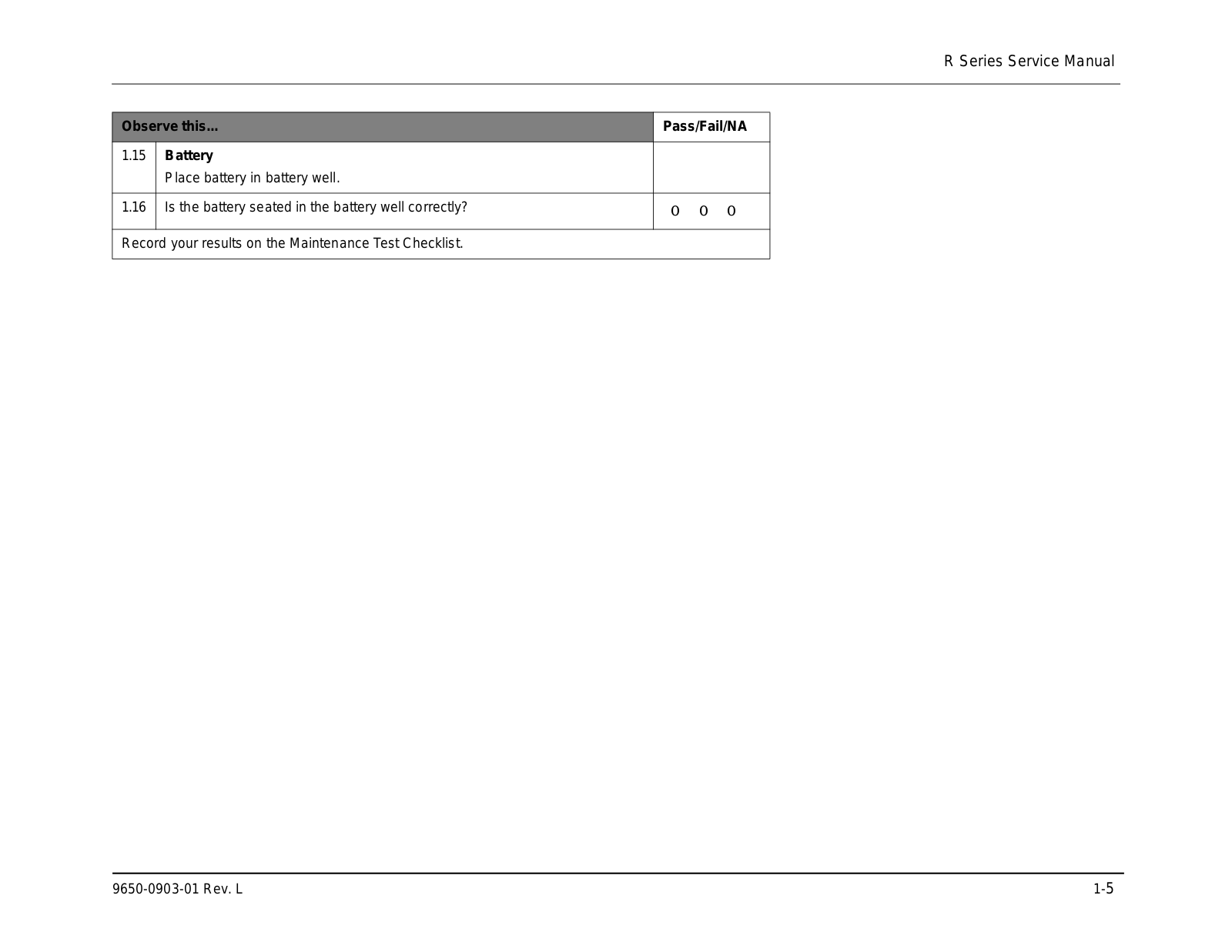
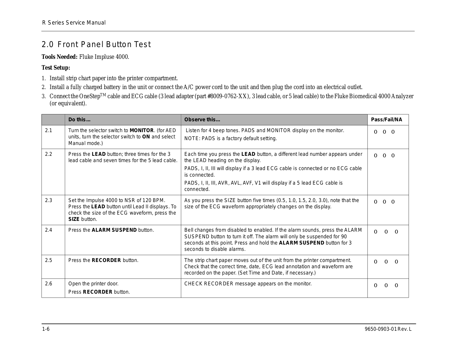
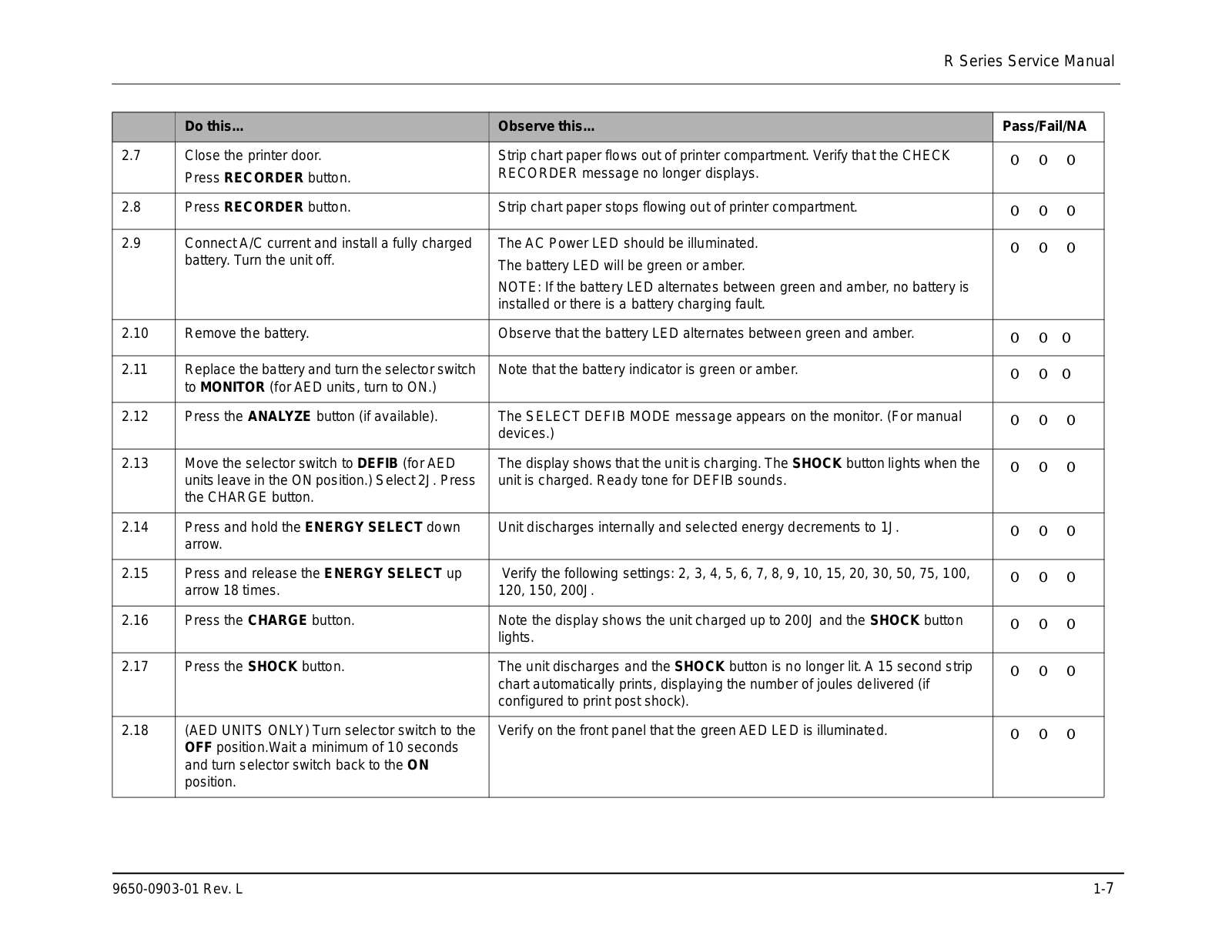
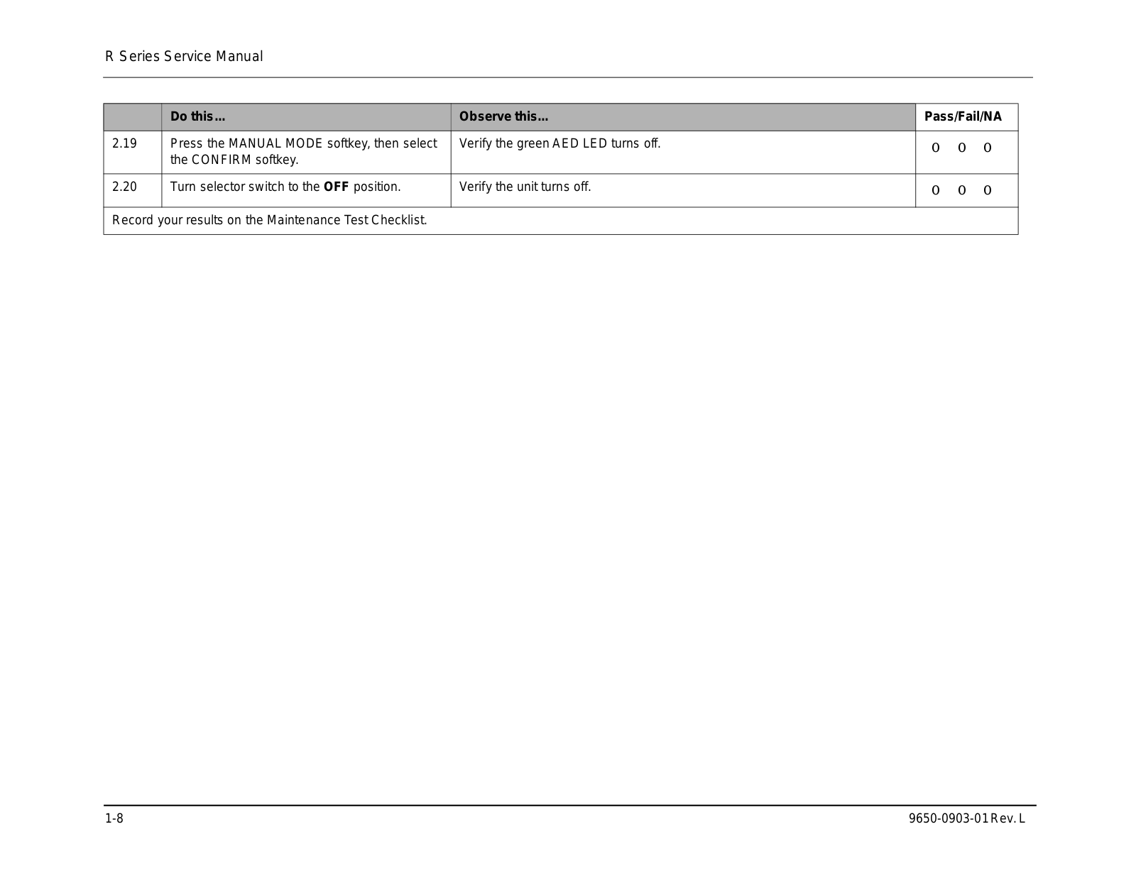
R Series
User manual
6 pgs
3.63 Mb
1
User manual
70 pgs
1.77 Mb
1
User Manual
20 pgs
462.51 Kb
0
User Manual
74 pgs
1.92 Mb
0
User Manual
28 pgs
1.03 Mb
0
User Manual
22 pgs
348.14 Kb
0
User Manual
12 pgs
2.11 Mb
0
User Manual
78 pgs
8.92 Mb
0
User Manual
78 pgs
8.51 Mb
0
User Manual
538 pgs
23.61 Mb
0
Operator's Manual
88 pgs
2.95 Mb
0
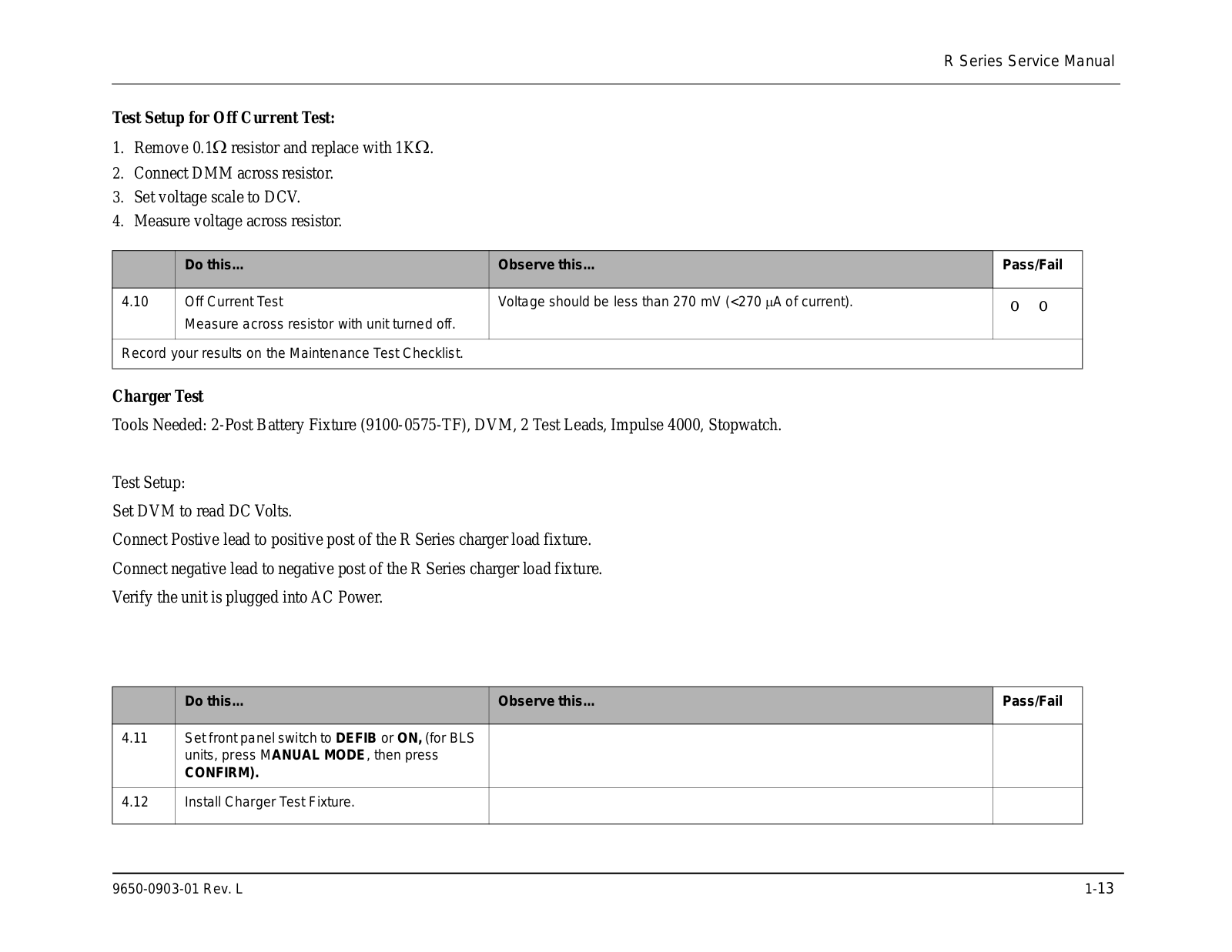
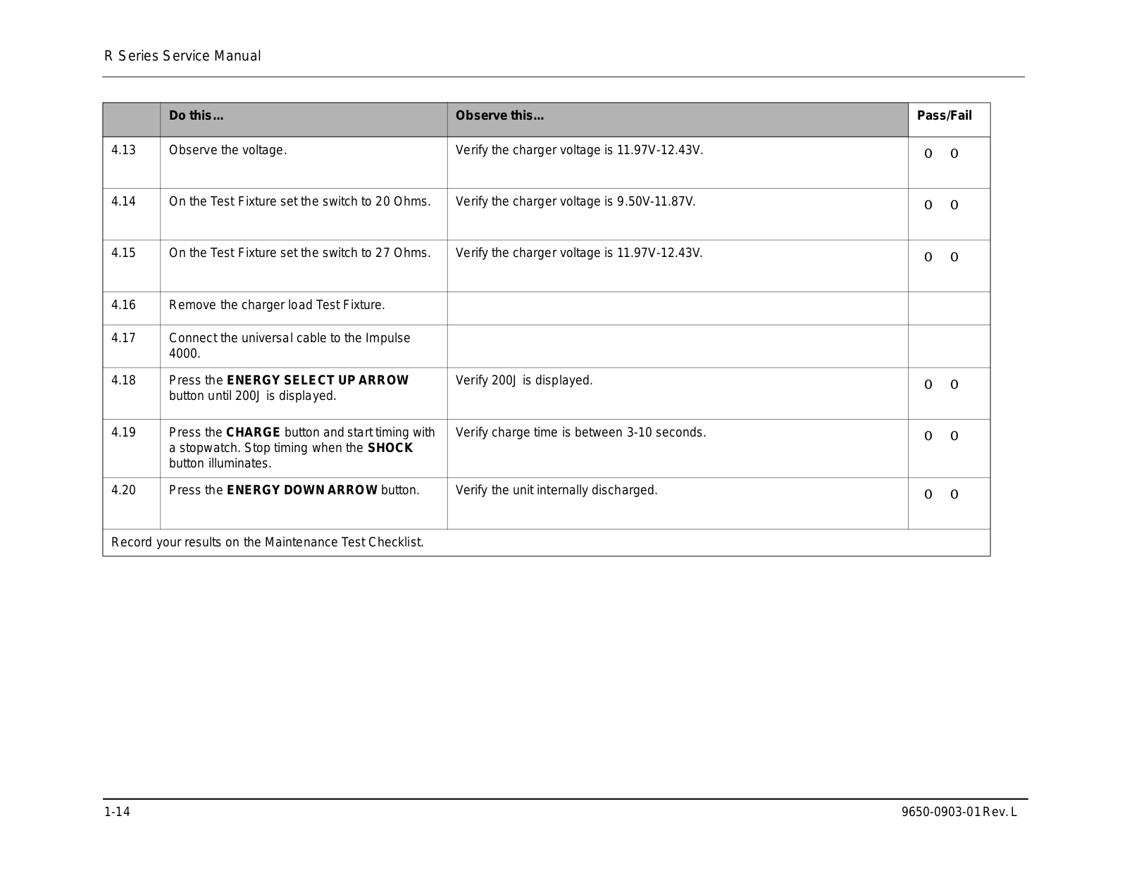
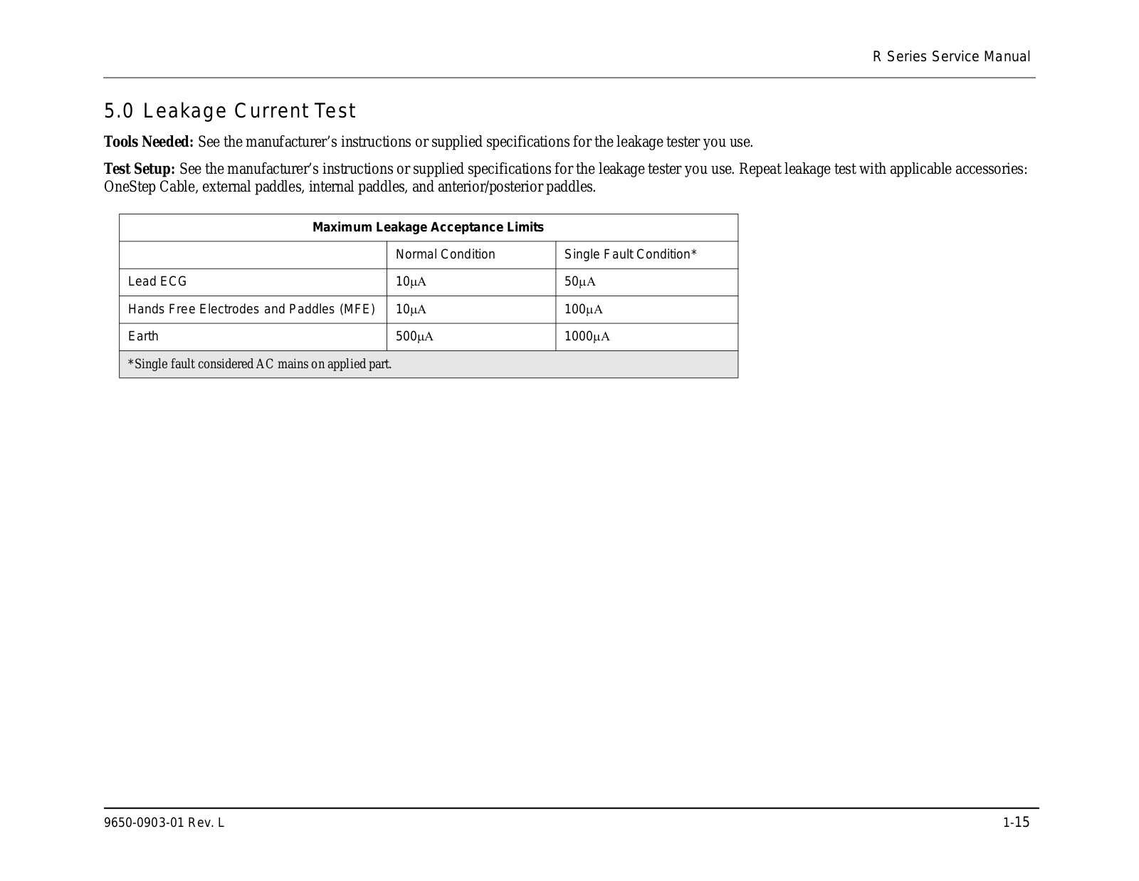
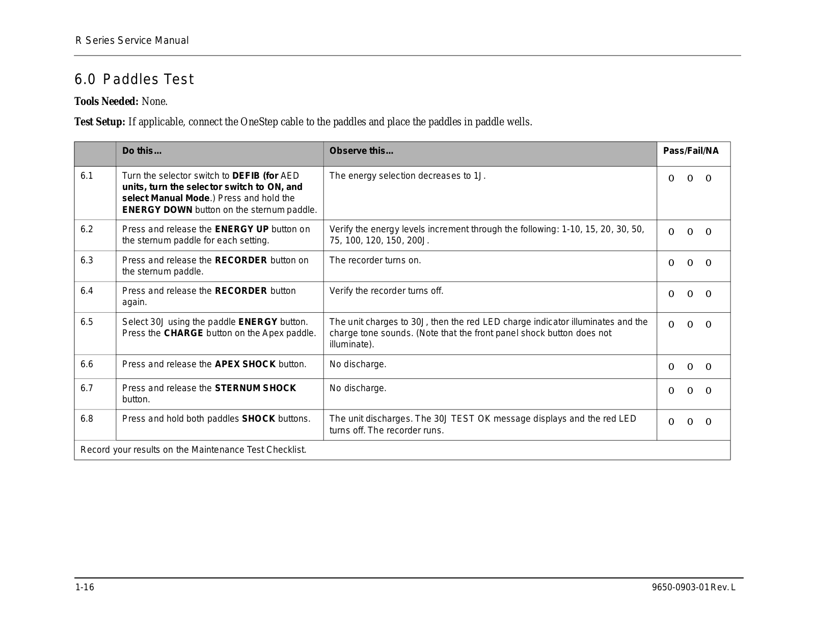
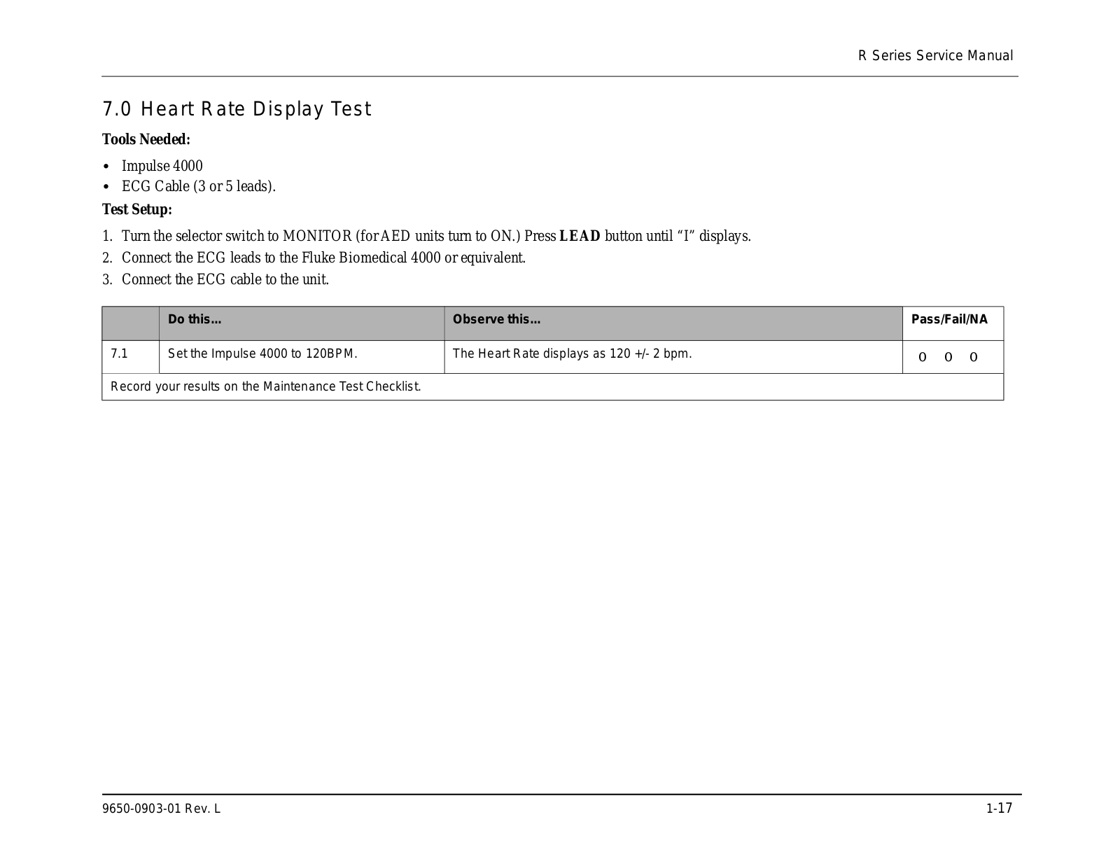
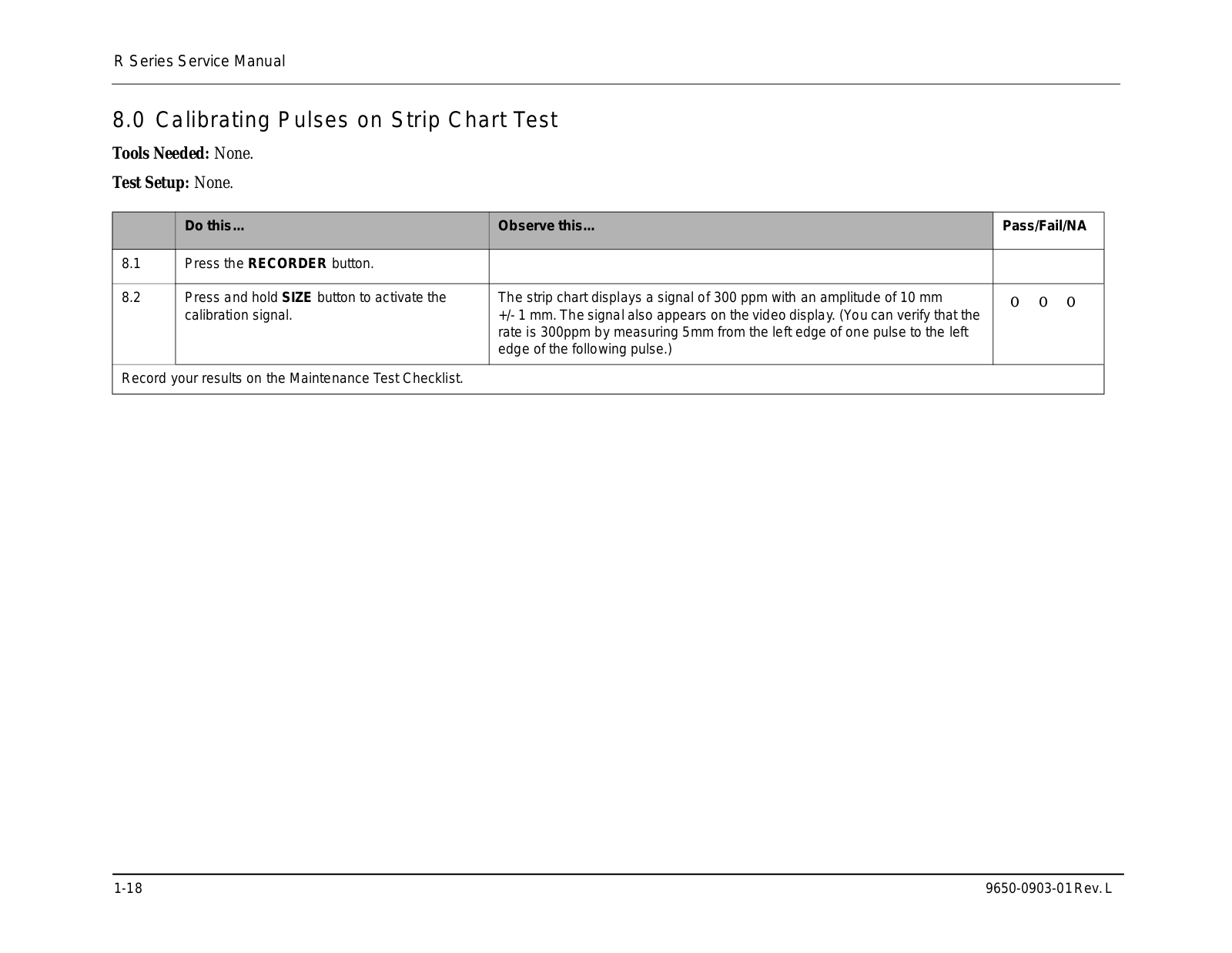
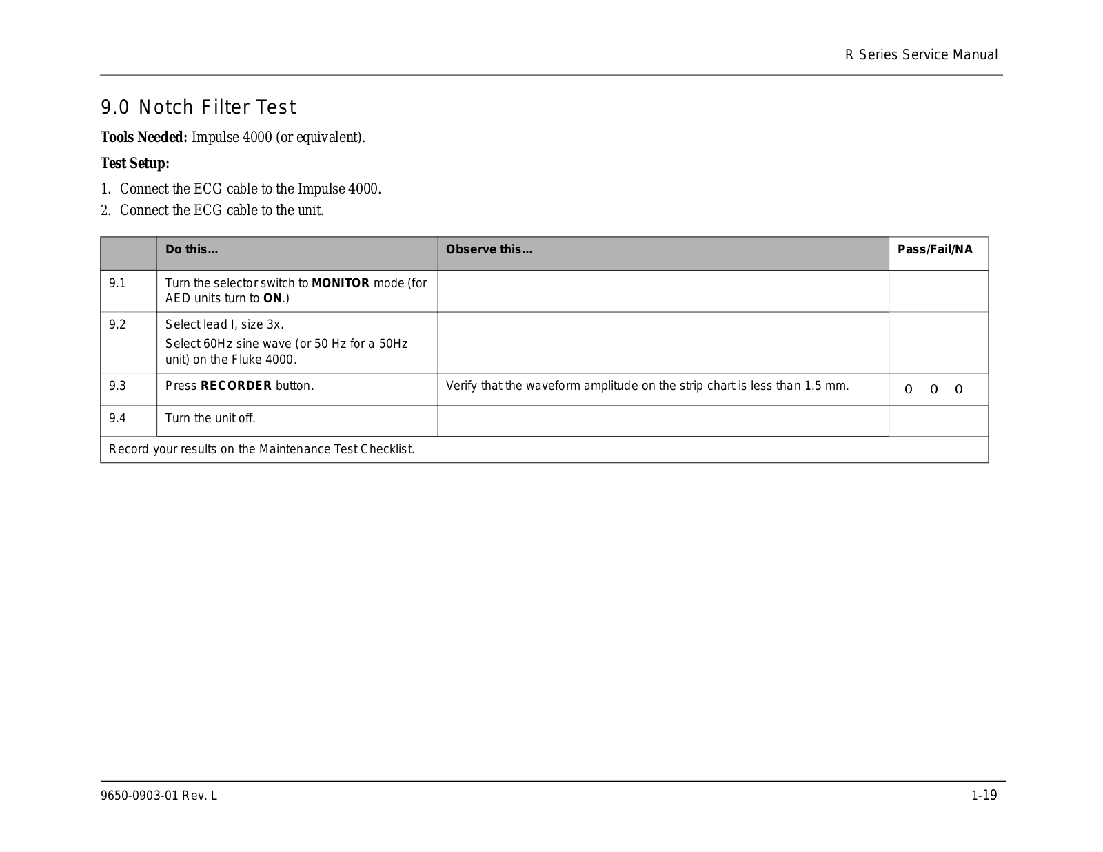
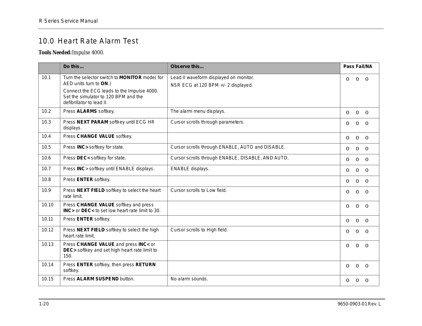
Service manual
548 pgs
18.61 Mb
2
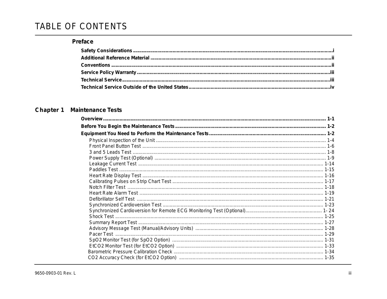
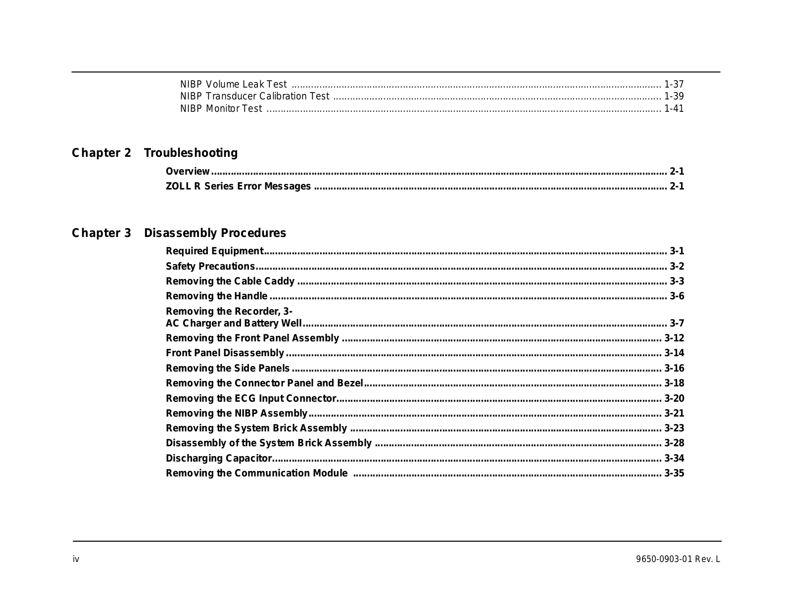
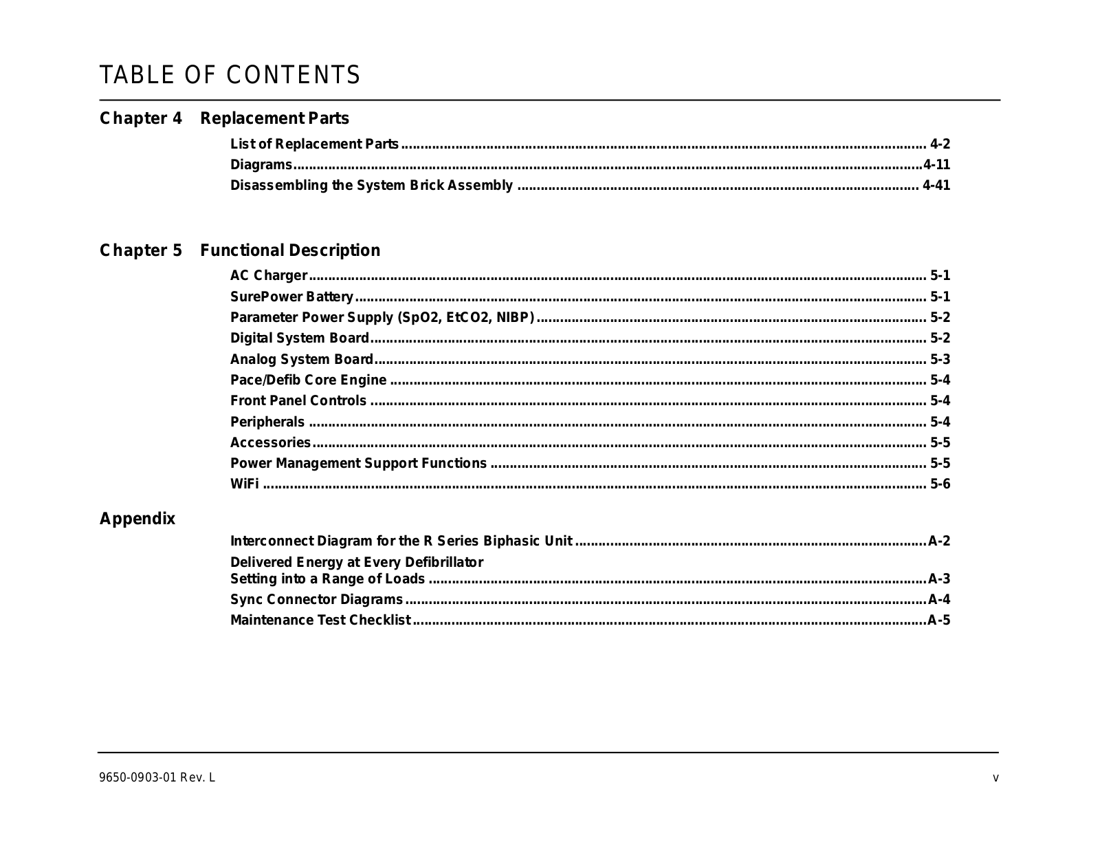
Table of contents
Loading...
Zoll R Series Service manual
...
Zoll Service manual
Download
4.3
(
3
)
Loading...
+
518
hidden pages
Unhide
You need points to download manuals.
1 point = 1 manual.
You can buy points or you can get point for every manual you upload.
Buy points
Upload your manuals


 Loading... Loading...