


Resuscitation System Model 100
User Guide
P/N 12555-001 Rev 3


 User Guide
Notice
About this Guide
The information in this User Guide applies to the ZOLL AutoPulse Resuscitation System Model 100.
ZOLL shall not be liable for errors contained herein or for incidental or consequential damages in connection with the furnishing, performance, or use of this material.
Copyright
© Copyright ZOLL 2012. All rights reserved.
No part of this publication may be reproduced, stored in a retrieval system, or transmitted, in any form or by any means, mechanical, electronic, photocopying, recording, or otherwise, without prior written permission of ZOLL.
AutoPulse and LifeBand® are trademarks of ZOLL. All other trademarks mentioned herein belong to their respective owners.
0344
USA |
|
|
EU Authorized Representative |
ZOLL Circulation |
|
|
ZOLL International Holding B.V. |
|
|
||
650 Almanor Avenue |
|
|
Newtonweg 18 |
Sunnyvale, CA 94085 USA |
|
|
6662 PV ELST |
|
|
|
The Netherlands |
t: +1.800.348.9011 |
|
|
|
(or: +1.978.421.9655) |
|
|
t: +31 481 366 410 |
Page ii |
P/N 12555-001 Rev 3 |


 User Guide
Table of Contents
Figures ...................................................................................................................... |
v |
|
Tables ...................................................................................................................... |
vii |
|
Who Should Read this Guide ................................................................................. |
ix |
|
General Warnings and Precautions ....................................................................... |
ix |
|
Symbols ................................................................................................................... |
xi |
|
1 Introduction of the AutoPulse® ....................................................................... |
1-1 |
|
1.1 |
Indication for Use ............................................................................................................ |
1-1 |
1.2 |
Description of the System ................................................................................................ |
1-1 |
1.3 |
System Components ....................................................................................................... |
1-2 |
1.3.1 AutoPulse Platform .................................................................................................. |
1-2 |
|
1.3.2 LifeBand Load-distributing Band (LDB) ...................................................................... |
1-3 |
|
1.3.3 AutoPulse Power System ......................................................................................... |
1-3 |
|
1.4 |
User Controls and Indicators ............................................................................................ |
1-4 |
1.4.1 ON/OFF Button ........................................................................................................ |
1-4 |
|
1.4.2 User Controls ........................................................................................................... |
1-4 |
|
|
1.4.2.1 Start/Continue Button ....................................................................................... |
1-5 |
|
1.4.2.2 Stop/Cancel Button ........................................................................................... |
1-5 |
|
1.4.2.3 Menu/Mode Switch Button ............................................................................... |
1-6 |
|
1.4.2.4 Move Up/Move Down Button ........................................................................... |
1-6 |
|
1.4.2.5 Select Choice Button ........................................................................................ |
1-7 |
|
1.4.2.6 Tone Mute Button ............................................................................................ |
1-7 |
|
1.4.2.7 Increase/Decrease Contrast Button .................................................................... |
1-8 |
|
1.4.2.8 Power (Green LED) ............................................................................................ |
1-9 |
|
1.4.2.9 Alert (Red LED) ................................................................................................. |
1-9 |
1.4.3 Battery Charge Status .............................................................................................. |
1-9 |
|
1.4.4 Performance Characteristics ................................................................................... |
1-11 |
|
2 Preparing the AutoPulse for Use ..................................................................... |
2-1 |
|
2.1 |
LifeBand Load-distributing Band (LDB) ............................................................................. |
2-1 |
2.1.1 Installing the LifeBand .............................................................................................. |
2-1 |
|
2.1.2 Removing the LifeBand ............................................................................................ |
2-4 |
|
|
2.1.2.1 Removing a LifeBand that is Cut or Not in the Home Position ........................... |
2-7 |
2.2 |
Battery Installation and Removal ...................................................................................... |
2-9 |
2.2.1 AutoPulse Li-Ion Battery Installation and Removal ..................................................... |
2-9 |
|
2.2.2 AutoPulse NiMH Battery Installation and Removal .................................................. |
2-10 |
|
2.3 |
Administrative Menu: User Pre-set Options .................................................................... |
2-11 |
3 Using the AutoPulse ......................................................................................... |
3-1 |
|
3.1 |
Deploying the AutoPulse System ..................................................................................... |
3-1 |
3.2 |
Starting Chest Compressions ........................................................................................... |
3-8 |
3.3 |
Ending Active Device Use .............................................................................................. |
3-15 |
|
|
|
P/N 12555-001 Rev 3 |
Page iii |
|


 User Guide
3.4 |
Preparing the AutoPulse for Its Next Use ........................................................................ |
3-15 |
3.5 |
Periodic Electrocardiogram (ECG) Monitoring and/or Defibrillation ................................. |
3-15 |
3.6 |
Patient Alignment and Securing for Transport ................................................................ |
3-16 |
3.6.1 Recommended Method of Patient Extrication ......................................................... |
3-17 |
|
3.7 |
Viewing AutoPulse Platform Information ....................................................................... |
3-19 |
3.8 |
Uploading AutoPulse Information to your PC ................................................................. |
3-20 |
3.8.1 Information Upload Procedure ............................................................................... |
3-21 |
|
4 Maintaining the AutoPulse System ................................................................ |
4-1 |
|
4.1 |
Charging Batteries in the AutoPulse Multi-Chemistry Battery Charger .............................. |
4-1 |
4.2 |
Cleaning the AutoPulse Platform ..................................................................................... |
4-3 |
4.3 |
Storing the AutoPulse Platform ........................................................................................ |
4-3 |
4.4 |
Maintenance ................................................................................................................... |
4-3 |
5 Troubleshooting Procedures ........................................................................... |
5-1 |
|
5.1 |
Troubleshooting Batteries ................................................................................................ |
5-1 |
5.2 |
Troubleshooting User Advisories and Faults ..................................................................... |
5-2 |
5.2.1 User Advisory (45) .................................................................................................... |
5-4 |
|
5.3 |
Troubleshooting Errors .................................................................................................... |
5-5 |
Appendix A AutoPulse Daily Checklist .............................................................. |
A-1 |
|
Appendix B Technical Specifications ................................................................. |
B-1 |
|
B.1 |
Patient Parameters ........................................................................................................... |
B-1 |
B.2 |
LifeBand .......................................................................................................................... |
B-1 |
B.3 |
Operating Parameters ...................................................................................................... |
B-1 |
B.4 |
Platform Physical ............................................................................................................. |
B-1 |
B.5 |
Platform Environmental ................................................................................................... |
B-2 |
B.6 |
Li-Ion Battery Physical and Environmental ........................................................................ |
B-2 |
B.7 |
NiMH Battery Physical and Environmental ........................................................................ |
B-4 |
B.8 |
Multi-Chemistry Battery Charger Physical And Environmental .......................................... |
B-5 |
B.9 |
Limited Warranty for AutoPulse Resuscitation System ...................................................... |
B-6 |
Appendix C AutoPulse Parts and Accessories ................................................... |
C-1 |
|
Index ....................................................................................................................... |
I-1 |
|
Page iv |
P/N 12555-001 Rev 3 |


 User Guide
Figures
Figure 1-1 The AutoPulse System ........................................................................................... |
1-2 |
|
Figure 1-2 AutoPulse Platform (Patient and Back Surfaces) ..................................................... |
1-3 |
|
Figure 1-3 ON/OFF Button Location ....................................................................................... |
1-4 |
|
Figure 1-4 User Control Panel ................................................................................................ |
1-5 |
|
Figure 1-5 Low Battery Warning ............................................................................................ |
1-9 |
|
Figure 2-1 Sliding the LifeBand Band Clip into the Driveshaft Slot .......................................... |
2-1 |
|
Figure 2-2 Seating the LifeBand Band Clip Properly into the Driveshaft Slot ........................... |
2-2 |
|
Figure 2-3 |
Snapping the LifeBand Cover Plate into Place ........................................................ |
2-3 |
Figure 2-4 |
Flip Down the Hinged Belt Guards of the LifeBand ................................................ |
2-3 |
Figure 2-5 |
Flip Up the Hinged Belt Guards of the LifeBand ..................................................... |
2-4 |
Figure 2-6 |
Pinching the Locking Tabs of the LifeBand ............................................................ |
2-5 |
Figure 2-7 Removing the LifeBand from the AutoPulse Platform. ...........................................2-6
Figure 2-8 LifeBand NOT in the Home Position: Do Not Remove! |
...........................................2-7 |
Figure 2-9 Positioning the LifeBand for Removal .................................................................... |
2-8 |
Figure 2-10 LifeBand in the Home Position: Ready for Removal .............................................. |
2-8 |
Figure 2-11 AutoPulse Li-Ion Battery Installation and Removal ............................................... |
2-9 |
Figure 2-12 AutoPulse NiMH Battery Installation and Removal ............................................. |
2-10 |
Figure 2-13 Administrative Menu ........................................................................................ |
2-12 |
Figure 2-14 Compression Mode Menu ................................................................................ |
2-13 |
Figure 2-15 Mute Duration Menu ........................................................................................ |
2-14 |
Figure 2-16 Ventilation/Pause Tone Volume Menu ............................................................... |
2-15 |
Figure 3-1 ON/OFF Button Location ....................................................................................... |
3-2 |
Figure 3-2 Self-Test Display Panel Screen ............................................................................... |
3-2 |
Figure 3-3 Patient-Readiness Display Panel Screen ................................................................. |
3-3 |
Figure 3-4 Cutting Patient Clothing and Positioning of AutoPulse .......................................... |
3-4 |
Figure 3-5 Removal of all Clothing from the Torso ................................................................. |
3-5 |
Figure 3-6 Patient Alignment ................................................................................................. |
3-6 |
Figure 3-7 Aligning the LifeBand ........................................................................................... |
3-7 |
Figure 3-8 Fastening the LifeBand .......................................................................................... |
3-8 |
Figure 3-9 Analyzing Patient Size Display Panel Screen ........................................................... |
3-9 |
Figure 3-10 Verifying Patient Alignment Display Panel Screen .............................................. |
3-10 |
Figure 3-11 Chest Compression Display Panel Screen .......................................................... |
3-11 |
Figure 3-12 Ventilation Pause Display Panel Screen .............................................................. |
3-12 |
Figure 3-13 Mode Change Confirm Display Panel Screen ..................................................... |
3-13 |
Figure 3-14 Stopping Compressions Display Panel Screen .................................................... |
3-14 |
Figure 3-15 Restart/Continue Compressions Display Panel Screen ........................................ |
3-14 |
Figure 3-16 Securing the Patient for Transport ..................................................................... |
3-17 |
Figure 3-17 Transporting the Patient ................................................................................... |
3-18 |
Figure 3-18 Main Menu ...................................................................................................... |
3-21 |
Figure 3-19 Infrared Communication Set-up ........................................................................ |
3-21 |
Figure 3-20 Waiting for Connection... Display Panel Screen ................................................. |
3-22 |
Figure 3-21 Connected Display Panel Screen ....................................................................... |
3-22 |
|
|
P/N 12555-001 Rev 3 |
Page v |


 User Guide
Figure 3-22 Transmitting... Display Panel Screen .................................................................. |
3-23 |
|
Figure 4-1 Multi-Chemistry Battery Charger with Charging Bay ............................................. |
4-2 |
|
Figure 4-2 Multi-Chemistry Battery Charger Control Panel ..................................................... |
4-2 |
|
Figure 5-1 Low Battery Warning ............................................................................................ |
5-1 |
|
Figure 5-2 Replace Battery Screen .......................................................................................... |
5-2 |
|
Figure 5-3 |
A User Advisory Screen ......................................................................................... |
5-3 |
Figure 5-4 |
A Fault Screen ....................................................................................................... |
5-3 |
Figure 5-5 |
User Advisory (45) ................................................................................................. |
5-4 |
Figure 5-6 |
System Error Screen .............................................................................................. |
5-5 |
Page vi |
P/N 12555-001 Rev 3 |


 User Guide
Tables
Table 1-1 Patient/AutoPulse Operating Parameters ................................................................ |
1-1 |
|
Table 1-2 Battery Charge Status Indicator Specifics .............................................................. |
1-10 |
|
Table 1-3 Operating Characteristics ..................................................................................... |
1-11 |
|
Table B-1 Operating Parameters ............................................................................................ |
B-1 |
|
Table B-2 Physical Specifications ............................................................................................ |
B-1 |
|
Table B-3 |
Environmental Specifications .................................................................................. |
B-2 |
Table B-4 |
Li-Ion Battery Specifications .................................................................................... |
B-2 |
Table B-5 |
NiMH Battery Specifications ................................................................................... |
B-4 |
Table B-6 |
Multi-Chemistry Battery Charger Specifications ...................................................... |
B-5 |
Table C-1 AutoPulse Parts and Accessories ............................................................................ |
C-1 |
|
Page vii |
P/N 12555-001 Rev 3 |


 User Guide
[This page left intentionally blank.]
Page viii |
P/N 12555-001 Rev 3 |


 User Guide
Preface
This document describes the operating steps and maintenance requirements for the AutoPulse® Resuscitation System Model 100 (also known as the AutoPulse).
Proper use of the AutoPulse requires a thorough understanding of the product, appropriate training and practice.
Please read the entire User Guide before operating the AutoPulse.
Who Should Read this Guide
This document should be read by personnel who will use this product and who are trained in Basic Life Support (BLS) and/or Advanced Life Support (ALS) techniques. This includes emergency medical technicians, paramedics, nurses, physicians, police, and fire rescue personnel, and people certified to administer cardiopulmonary resuscitation (CPR).
General Warnings and Precautions
Warning:
•The AutoPulse is intended for use on adults, 18 years of age or older.
•The AutoPulse is not intended for patients with traumatic injury (wounds resulting from sudden physical injury or violence).
•When CPR is indicated, it should start immediately and should not be postponed.
•The AutoPulse must be used only in cases that manual CPR would normally be initiated. Personnel certified in manual CPR must always be present during the AutoPulse System operation.
•The AutoPulse Platform is not intended to be the sole means of carrying a patient. The AutoPulse Platform should be secured to the top of a backboard or other equipment used to carry or transport the patient, if necessary. During transport, regular checks of the patient’s alignment should be performed.
•Failure to properly position the LifeBand® at the patient’s armpit line may cause injury to the patient.
•Do not place or position the patient on the AutoPulse Platform in either a facedown orientation or on the patient’s side.
•If a system error occurs, immediately revert to manual CPR.
P/N 12555-001 Rev 3 |
Page ix |


 User Guide
Warning:
•If a user advisory or fault cannot be cleared or a system error occurs during active operation, immediately revert to manual CPR.
•Do not strap across, or otherwise constrain, the LifeBand. Constraining the movement of the LifeBand can damage or break the LifeBand.
•Do not touch the patient while the AutoPulse is analyzing the patient’s size.
•Failure to properly position a patient, both vertically and laterally with respect to the AutoPulse Platform, may cause injury to the patient.
•If you must move or realign the patient, you must press the Stop/Cancel button before adjustment.
•Do not place your hands or any other objects on or under the LifeBand while the AutoPulse is analyzing the patient or during active operation.
•Operating the AutoPulse on a patient for extended periods of time may result in minor skin irritation to the patient.
•Check the patient’s chest rise during ventilation during active operation.
•Do not use the AutoPulse in the presence of an oxygen-rich (greater than 25% oxygen) atmosphere, flammable anesthetics, or other flammable agents (such as gasoline). Using the AutoPulse near the site of a gasoline spill may cause an explosion.
•No modification of the AutoPulse Platform, the LifeBand, or the AutoPulse Power System is allowed.
Caution: United States federal law restricts this device to sale by or on the order of a licensed physician.
Caution: The AutoPulse is designed to be used only with ZOLL-approved accessories. The AutoPulse will perform improperly if non-approved accessories are used.
Caution: Only use ZOLL Batteries specifically designed for use with the AutoPulse. The use of other batteries may cause permanent damage to the AutoPulse and will void the warranty.
Caution: Make sure that the LifeBand is not twisted before automatic compressions begin.
Caution: Do not submerge the AutoPulse Platform in liquid.
Caution: Use care while using sharp instruments around the LifeBand.
Caution: Do not block the vents of the AutoPulse.
Caution: Do not use the AutoPulse alone as a patient transportation aid.
Page x |
P/N 12555-001 Rev 3 |


 User Guide
Caution: Straps or restraints used for transportation purposes must not interfere with the operation of the AutoPulse. Specifically, straps across the patient’s chest may restrict the compression/ decompression of the chest. In general, strapping schemes must not alter the alignment of the patient to the AutoPulse.
Caution: Motion can cause the patient to shift and restraints to loosen, so care should be given to the initial strapping for alignment of the patient to the AutoPulse. Regular checks of patient alignment to the AutoPulse and alignment of the LifeBand to the patient's mid-axillary line should be made if the AutoPulse is performing active compressions, or before active compressions are restarted.
Caution: Remove the protective plastic cap from the Battery before attempting to charge the Battery.
Caution: Do not autoclave the AutoPulse Platform, the LifeBand, or the AutoPulse Power System.
Caution: Retain the original product literature for future reference.
Symbols
The symbols below may be found in this User Guide, on the AutoPulse Platform, or on the LifeBand.
Follow instructions for use
Date of Manufacture
Manufacturer
Authorized Representative
Serial Number
SN
Defibrillation Protected, Type BF Patient Connection
Degree of Protection Provided by Enclosure Per IEC 60529
IP24
Do Not Reuse—Single Use Only
P/N 12555-001 Rev 3 |
Page xi |


 User Guide
[This page left intentionally blank.]
Page xii |
P/N 12555-001 Rev 3 |


 User Guide
1Introduction of the AutoPulse®
For years, a variety of attempts have been made to overcome the limitations of manual cardiopulmonary resuscitation (CPR). ZOLL has developed a practical solution as an adjunct to the method used by medical professionals to perform CPR chest compressions. The AutoPulse is the resulting product.
1.1Indication for Use
The AutoPulse is intended to be used as an adjunct to manual CPR, on adult patients only, in cases of clinical death as defined by a lack of spontaneous breathing and pulse.
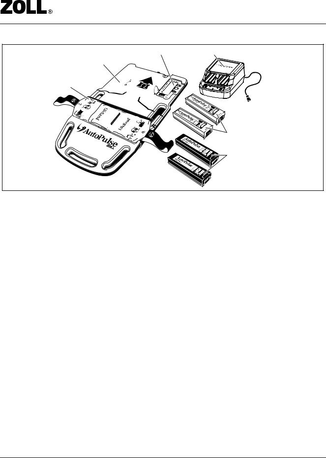
1.2Description of the System
The AutoPulse is an automated, portable, battery-powered chest compressor, which provides chest compressions as an adjunct to performing manual CPR (see Figure 1-1). Use of the AutoPulse is intended to reduce the impact of rescuer fatigue and will enable the rescuer to address additional patient needs.
The AutoPulse has the following operating parameters:
•Chest displacement: equal to 20% reduction in anterior-posterior chest depth.
•Consistent compression rate and depth.
•Physiological duty cycle: fixed at 50 ± 5%.
•Standardized 30:2, or 15:2 compressions (30 or 15 compressions followed by two consecutive 1.5 second ventilation pauses) or continuous compressions (user selectable).
Table 1-1 provides the patient/AutoPulse operating parameters.
Table 1-1 Patient/AutoPulse Operating Parameters
Patient Parameter |
AutoPulse Specification |
|
|
Patient chest circumference permitted |
29.9 to 51.2 in. (76 to 130 cm) |
|
|
Patient chest width permitted |
9.8 to 15 in. (25 to 38 cm) |
|
|
Maximum patient weight permitted |
300 lbs.(136 kg) |
|
|
P/N 12555-001 Rev 3 |
Page 1-1 |


 User Guide
User Control Panel |
Multi-Chemistry |
AutoPulse Platform |
Battery Charger |
|
|
LifeBand |
|
Li-Ion Batteries
(Primary and Spare)
or
NiMH Batteries
(Primary and Spare)
Figure 1-1 The AutoPulse System
1.3System Components
Figure 1-1 shows the main components of the AutoPulse System.
The AutoPulse consists of the following:
•AutoPulse Platform
•LifeBand
•AutoPulse Power System
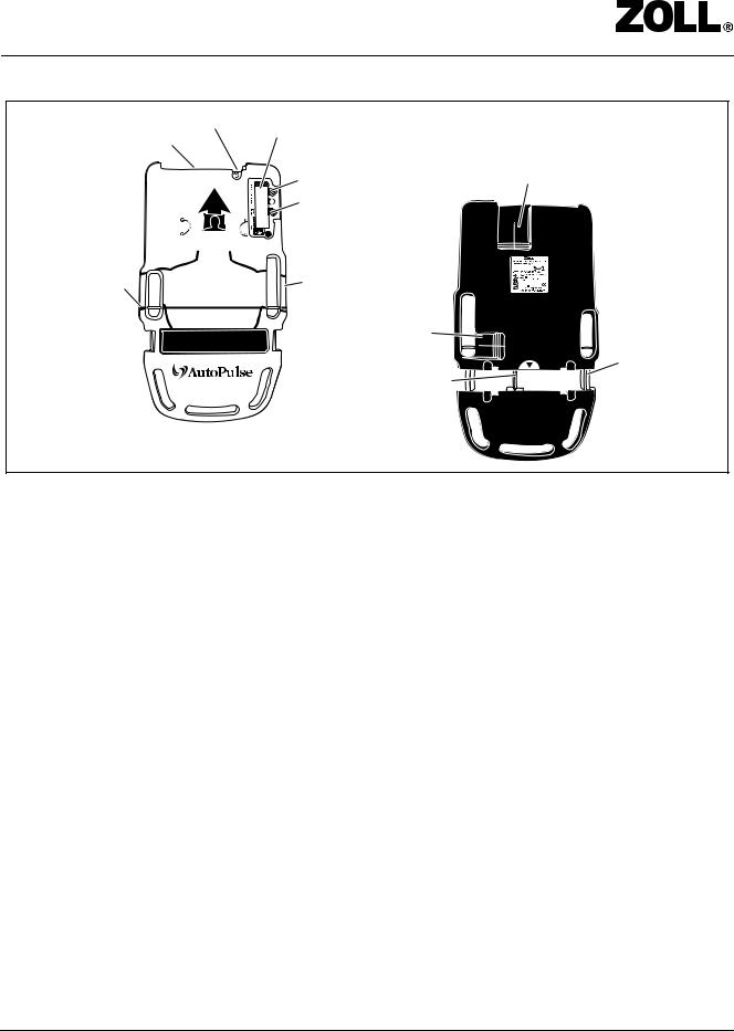
1.3.1AutoPulse Platform
The AutoPulse Platform contains the mechanical drive mechanism, control system, and electronics necessary to generate and control the force required to perform mechanical chest compressions. User controls and indicators are contained in the User Control Panel.
Figure 1-2 shows the patient surface (front) and back surface details of the AutoPulse Platform. The AutoPulse Platform features carry handles to facilitate transporting it to the scene of the arrest.
Page 1-2 |
P/N 12555-001 Rev 3 |


 User Guide
ON/OFF Button |
User Control Panel |
|
|
Battery |
Back Surface |
||
|
|||
|
Start/Continue Button |
Cooling Vent |
|
|
|
||
|
Stop/Cancel Button |
|
Patient Alignment |
Carry Handle |
Reference |
|
Cooling Vent |
|
|
AutoPulse |
LifeBand® |
|
Roller Guide |
||
Slotted Drive Shaft |
||
|
Patient Surface
Figure 1-2 AutoPulse Platform (Patient and Back Surfaces)
1.3.2LifeBand Load-distributing Band (LDB)
The LifeBand is a load-distributing band (LDB) that consists of a cover plate and two bands integrated with a compression pad with a Velcro® fastener. Attached to the AutoPulse Platform, the LifeBand is automatically adjusted to the patient and provides compressions to the patient's chest in the region of the heart. The latex-free LifeBand is a single-use component that is attached to the AutoPulse Platform before each use.
1.3.3AutoPulse Power System
The AutoPulse Power System consists of a battery and battery charger:
•Battery: the AutoPulse Li-Ion Battery (a Lithium-Ion battery), or the AutoPulse NiMH Battery (a Nickel-Metal Hydride battery)
•Battery charger: the AutoPulse Multi-Chemistry Battery Charger (which charges both the AutoPulse NiMH Battery and the AutoPulse Li-Ion Battery)
Batteries: Both the AutoPulse Li-Ion Battery and the AutoPulse NiMH Battery are proprietary, rechargeable, removable batteries, and each is designed to supply power for AutoPulse operation. Both Batteries are mechanically keyed to the AutoPulse Platform and to the AutoPulse Multi-Chemistry Battery Charger to facilitate correct installation. One end of each Battery contains connections for power and communication to the Charger and to the AutoPulse Platform. A Battery Status Check button illuminates both Batteries’ status light-emitting diodes (LED’s).
P/N 12555-001 Rev 3 |
Page 1-3 |


 User Guide
Battery Charger: The AutoPulse Multi-Chemistry Battery Charger is a stand alone unit designed to charge and automatically maintain both the AutoPulse Li-Ion Battery and the AutoPulse NiMH Battery. The Multi-Chemistry Battery Charger has two charging bays, and each bay has its own indicators.
AutoPulse Batteries should always be properly maintained and be fully charged and ready for use before deploying the AutoPulse.
For more information, refer to the AutoPulse Power System User Guide.
1.4User Controls and Indicators
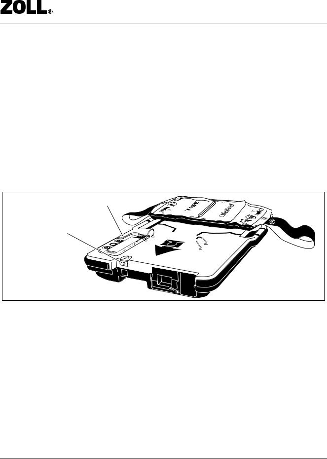
1.4.1ON/OFF Button
The ON/OFF button is located adjacent to the Battery on the AutoPulse Platform (see Figure 1-3). Pressing the ON/OFF button once powers up the AutoPulse Platform and initiates a self-test. The User Control Panel’s green Power LED lights up. Pressing the ON/OFF button again powers down the AutoPulse Platform.
User Control Panel
ON/OFF button
Figure 1-3 ON/OFF Button Location
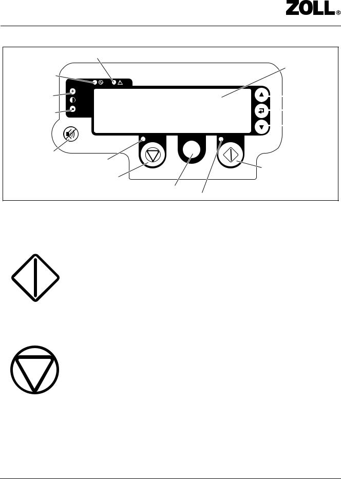
1.4.2User Controls
All user controls and indicators (except the ON/OFF button) are contained in User Control Panel (see Figure 1-4).
Page 1-4 |
P/N 12555-001 Rev 3 |


 User Guide
|
Alert LED (red) |
||
|
|
|
Display Panel |
Power LED (green) |
|
|
|
Increase Contrast |
|
|
Move Up |
|
|
||
Decrease Contrast |
|
|
Select Choice |
|
|
||
|
|
|
|
|
|
|
Move Down |
|
|
|
|
Tone Mute
Stop/Cancel LED
Start/Continue
Stop/Cancel
Menu/Mode Switch
Start/Continue LED
Figure 1-4 User Control Panel
1.4.2.1 Start/Continue Button
The green Start/Continue button is active when “Sta rt” or “Continue” appears on the display panel above the button and its green LED is illuminated.
Use the Start/Continue button to start or continue:
•Analyzing patient size
•Chest compressions
1.4.2.2Stop/Cancel Button
The orange Stop/Cancel button is active when “Stop” , “Quit”, “No Realign” or “Cancel” appears on the display panel above the but ton and its orange LED is illuminated.
Use the Stop/Cancel button to stop or cancel:
•Analyzing patient size (see Figure 3-9)
•Chest compressions (the AutoPulse releases the tension on the LifeBand) (see Figure 3-11)
•Verify patient alignment pause (see Figure 3-10)
P/N 12555-001 Rev 3 |
Page 1-5 |


 User Guide
1.4.2.3 Menu/Mode Switch Button
On initial power-up the gray Menu/Mode Switch button functions as the Menu button. Pressing this button allows you to:
1.Enter the communication mode
2.View last patient session information
3.View AutoPulse Platform information
4.View AutoPulse Battery information
For a complete description of the available information and how to access it, refer to section Section 3.7, “Viewing AutoPulse Pl atform Information,” on page 3-19. For more information on the Communication Mode, see Section 3.8, “Uploading AutoPulse Information to your PC,” on pa ge 3-20.
While the AutoPulse is actively doing compressions this button may function as the Mode Switch button. The Mode Switching feature is only active when the “30:2 or Continuous” or “15:2 or Continuous” option has been set in Mode section of the Administration Set-up (refer to section Section 2.3, “Administrative Menu: User Pre-set Options,” on pag e 2-11). If the “30:2 or Continuous” or “15:2 or Continuous” option has been set, the Mode Switch button will allow you to switch on-the-fly between 30:2 and Continuous or 15:2 and Continuous compression modes respectively.
The current mode (either “30:2”, “15:2” or “CONTINU OUS”) is displayed on the upper left portion of the User Display.
1.4.2.4 Move Up/Move Down Button
These buttons allow you to highlight for selection different menu or list items.
Pressing the Move Up button (upward pointing triangle) moves up to the next menu item.
Pressing the Move Down button (downward pointing triangle) moves down to the next menu item.
Page 1-6 |
P/N 12555-001 Rev 3 |


 User Guide
1.4.2.5 Select Choice Button
Pressing the Select Choice button selects the currently highlighted menu or list item.
1.4.2.6 Tone Mute Button
c
The ventilation and pause tones are always generated at the appropriate times by the system and cannot be turned off, but they can be muted for a short period of time as set in the Administration Menu (refer to section Section 2.3, “Administrative Menu: User Pre-set Options,” on pag e 2-11). Selecting the Tone Mute button will mute or enable the audible tone feedback generated by the AutoPulse. When the audio feedback is audible, pressing the Tone Mute button will mute it. When the audio feedback is muted, pressing the Tone Mute button will make it audible once again.
Once audio feedback has been muted with the Tone Mute button, it will automatically be reactivated when one of the following occurs:
1.The Mute Duration time set in the Administrative Menu has expired.
2.You press the Tone Mute button again.
3.You press the Start/Continue button to begin compressions.
4.You press the Stop button during compressions.
5.A low battery condition is reached (refer to section Section 1.4.3, “Low Battery Warning,” on page 1-9).
6.You switch between compression modes (refer to Figure 3-13 on page 3-13).
The icon displayed on the User Control Panel display when tones are audible.
The icon displayed on the User Control Panel display when tones are muted.
P/N 12555-001 Rev 3 |
Page 1-7 |


 User Guide
1.4.2.7 Increase/Decrease Contrast Button
Pressing the Increase Contrast button (plus sign) increases the contrast of the display panel screen. Each key press increases the contrast of the display panel screen by one level.
There are a total of eight contrast levels.
Pressing the Decrease Contrast button (minus sign) decreases the contrast of the display panel screen. Each key press decreases the contrast of the display panel screen by one level.
You can adjust the contrast of the display panel screen at any time the AutoPulse Platform is powered up.
Page 1-8 |
P/N 12555-001 Rev 3 |


 User Guide
1.4.2.8 Power (Green LED)
The green Power LED lights whenever the AutoPulse is powered on and able to respond to user input.
1.4.2.9 Alert (Red LED)
The red Alert LED lights whenever a user advisory, fault or system error condition exists for the AutoPulse. For a list of advisory, fault and error conditions, refer to Chapter 5, “Troubleshooting Procedures”.
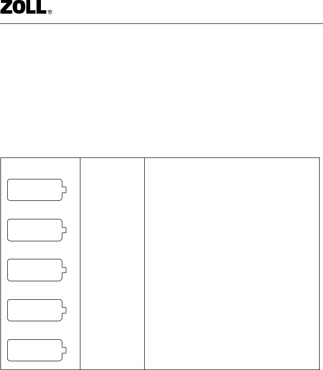
1.4.3Battery Charge Status
The User Control Panel displays the battery charge status. The Battery charge status icon only appears when the AutoPulse is powered up.
Indicates the level of charge of the Battery. A graphic battery icon indicating four proportional levels of battery charge is displayed.
3 0 : 2 |
L O W BA TTERY |
Figure 1-5 Low Battery Warning
When five minutes of active operation remain on a Battery, the User Control Panel will give a “Low Battery” indication (see Figure 1-5). The “Low Batt ery” indication will remain on until the Battery is replaced or depleted. The Low Battery warning display will be accompanied with an audio warning of four rapid beeps which will be followed by two beeps every 30 seconds until the battery is replaced or depleted. It is recommended that, if available, a fully-charged Battery be exchanged for the Battery with the low charge.
P/N 12555-001 Rev 3 |
Page 1-9 |


 User Guide
To exchange Batteries:
1.Press the Stop/Cancel button.
2.Press the ON/OFF button.
3.Remove the Battery (refer to Section 2.2, “Batter y Installation and Removal” for more information).
4.Install the fully-charged Battery (refer to Section 2.2, “Battery Installation and Removal” for more information).
5.Resume chest compressions (refer to Section 3.2, “Starting Chest Compressions” for more information).
Table 1-2 Battery Charge Status Indicator Specifics
Battery Charge Icon Bars Showing |
Charge Level |
||||||||
|
|
|
|
|
|
|
|
|
|
|
|
|
|
|
|
|
|
No bars showing. |
The Battery has been depleted. Replace the Battery |
|
|
|
|
|
|
|
|
|
immediately. |
|
|
|
|
|
|
|
|
|
|
|
|
|
|
|
|
|
|
|
|
|
|
|
|
|
|
|
|
|
|
|
|
|
|
|
|
|
|
One bar showing. |
The Battery’s capacity is less than one-third of a full charge. |
|
|
|
|
|
|
|
|
|
Be prepared to exchange this Battery with a fully-charged |
|
|
|
|
|
|
|
|
|
|
|
|
|
|
|
|
|
|
|
Battery. |
|
|
|
|
|
|
|
|
|
|
|
|
|
|
|
|
|
|
Two bars showing. |
The Battery’s capacity is between 33% and 66% of a full |
|
|
|
|
|
|
|
|
|
charge. |
|
|
|
|
|
|
|
|
|
|
|
|
|
|
|
|
|
|
|
|
|
|
|
|
|
|
|
|
|
|
|
|
|
|
|
|
|
|
Three bars showing. |
The Battery’s capacity is between 66% and 100% of a full |
|
|
|
|
|
|
|
|
|
charge. |
|
|
|
|
|
|
|
|
|
|
|
|
|
|
|
|
|
|
|
|
|
|
|
|
|
|
|
|
|
|
|
|
|
|
|
|
|
|
All bars showing. |
The Battery is fully charged. |
|
|
|
|
|
|
|
|
|
|
|
|
|
|
|
|
|
|
Page 1-10 |
|
|
|
P/N 12555-001 Rev 3 |
||||


 User Guide
1.4.4Performance Characteristics
The basic operating characteristics of the AutoPulse are shown in Table 1-3.
Table 1-3 Operating Characteristics
Operating Performance |
Specification |
|
|
|
|
Compression rate |
80 |
(± 5 compressions per minute) |
|
|
|
Compression modes (user selectable) |
• |
30:2 (30 compressions with two 1.5 second ventilation pauses) |
|
• |
Continuous compressions |
|
|
|
Duty cycle |
50 |
(± 5%) |
|
|
|
Compression depth |
20% of chest depth, +0.25/-0.5 inch |
|
|
|
|
P/N 12555-001 Rev 3 |
Page 1-11 |


 User Guide
[This page left intentionally blank.]
Page 1-12 |
P/N 12555-001 Rev 3 |


 User Guide
2Preparing the AutoPulse for Use
The AutoPulse System is delivered fully assembled, except for the LifeBand and the AutoPulse Battery.
2.1LifeBand Load-distributing Band (LDB)
Note: Do not cut the LifeBand before removing it from the AutoPulse. Cutting the LifeBand may cause the AutoPulse to report a Fault and will require specific steps to clear that Fault.
2.1.1Installing the LifeBand
1.Power off the device.
2.Place the AutoPulse Platform with the patient surface facing down on a smooth, flat surface.
Note: The driveshaft should be oriented so that the slot faces directly upward.
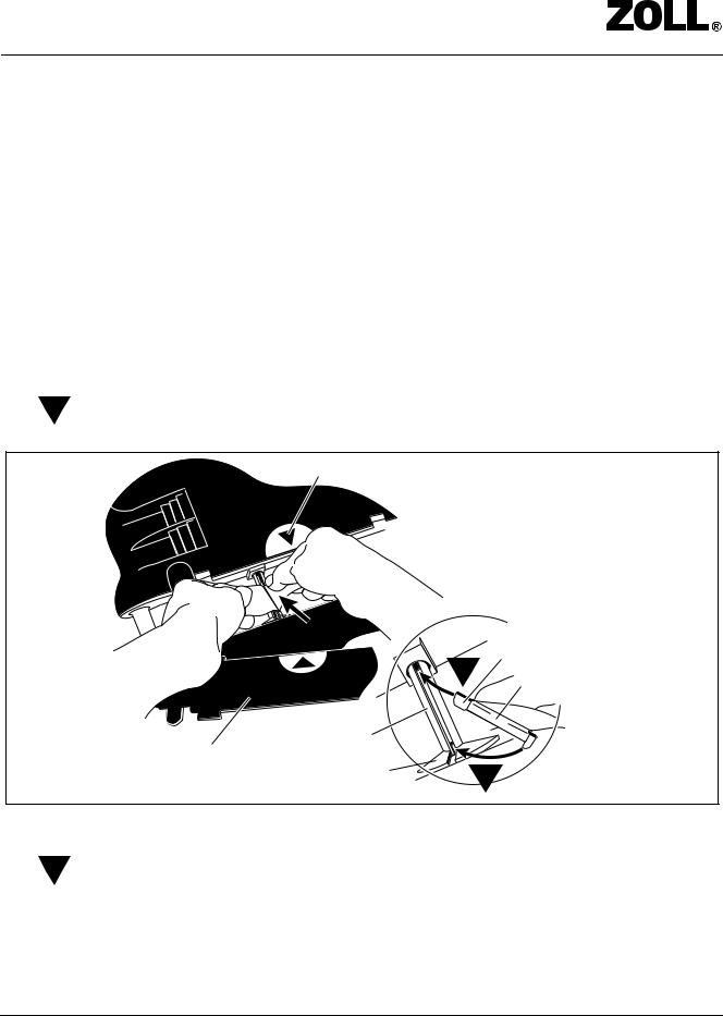
3.1 Insert the head end of the LifeBand band clip into the driveshaft slot. The correct direction is towards the LifeBand plate alignment arrow seen on the Platform (see Figure 2-1).
LifeBand plate alignment arrow
Slotted Drive Shaft
Cover Plate
Guide Plate 
Head End
1
Band Clip
 Tail End
2
Figure 2-1 Sliding the LifeBand Band Clip into the Driveshaft Slot
4.2 Once the head end of the LifeBand band clip is positioned into the slot, press the tail end of
the band clip into the slot of the guide plate until the band clip is fully seated in the driveshaft. You should feel it lock into place.
P/N 12555-001 Rev 3 |
Page 2-1 |


 User Guide
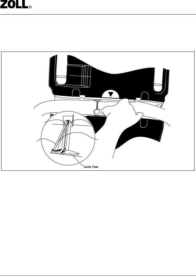
5.Make sure that the band clip is seated properly and fully into the slot on the driveshaft (see Figure 2-2).
Note: If the band clip is properly seated, you should be able to turn the driveshaft in each direction by hand.
Figure 2-2 Seating the LifeBand Band Clip Properly into the Driveshaft Slot
6.Ensure that both free ends of the LifeBand are oriented flat (not twisted) and away from the AutoPulse Platform. Inspect the LifeBand for any cuts or tears. Do not use the LifeBand if cuts or tears are present.
7.Line up the arrow on the LifeBand cover plate with the matching arrow on the Platform.
Page 2-2 |
P/N 12555-001 Rev 3 |


 User Guide
8.Snap the LifeBand cover plate in place by fully inserting the locking tabs into the slots on the AutoPulse (see Figure 2-3).
LifeBand Cover Plate
Alignment Arrows
Figure 2-3 Snapping the LifeBand Cover Plate into Place
9.Flip down and snap into place the hinged belt guards of the LifeBand cover plate to engage the LifeBand chest bands to the rollers (see Figure 2-4).
Belt Guard
Figure 2-4 Flip Down the Hinged Belt Guards of the LifeBand
P/N 12555-001 Rev 3 |
Page 2-3 |
 Loading...