ZOLL M Series User Manual

M Series® Service Manual
9650-0450-01 Rev R
0123
ZOLL Medical Corporation
269 Mill Road Chelmsford, MA USA 01824-4105
ZOLL International Holding B.V.
Newtonweg 18 6662 PV ELST The Netherlands
The issue date for the M Series Service Manual (REF 9650-0450-01 Rev. R) is March, 2013. If more than 3 years have elapsed since the issue date, contact ZOLL Medical Corporation to determine if additional product information updates are available.
Copyright © 2013 ZOLL Medical Corporation. All rights reserved. Rectilinear Biphasic, M Series, and ZOLL are trademarks or registered trademarks of ZOLL Medical Corporation in the United States and/or other countries.
Masimo is a trademark or registered trademark of Masimo Corporation in the United States and/or other countries.
9650-0450-01 Rev R
M Series Service Manual
TABLE OF CONTENTS
PREFACE ....................................................................................................................................................................................... V
Overview ..............................................................................................................................................................................................v
Safety Considerations ...........................................................................................................................................................................v
Additional Reference Material ........................................................................................................................................................... vi
Conventions .......................................................................................................................................................................................vii
Service Policy Warranty .................................................................................................................................................................... vii
Technical Service ..............................................................................................................................................................................vii
Technical Service for International Customers ................................................................................................................................viii
CHAPTER 1MAINTENANCE TESTS ..............................................................................................................................................1
Overview ..............................................................................................................................................................................................1
Before You Begin the Maintenance Tests ............................................................................................................................................2
Equipment that You Need to Perform the M Series Maintenance Tests ..............................................................................................3
Equipment You Need for the M Series Options Maintenance Tests ...................................................................................................4
1.0 Physical Inspection of the Unit...................................................................................................................................................... 5
2.0 Front Panel Button Test................................................................................................................................................................. 7
3.0 3, 5, and 12 Leads Test................................................................................................................................................................ 10
4.0 Power Supply Test (Optional)..................................................................................................................................................... 11
5.0 Leakage Current Test................................................................................................................................................................... 15
6.0 Paddles Test (If applicable)......................................................................................................................................................... 16
7.0 Heart Rate Display Test............................................................................................................................................................... 18
8.0 Calibrating Pulses on Strip Chart Test ........................................................................................................................................ 19
9.0 Notch Filter Test.......................................................................................................................................................................... 20
10.0 Heart Rate Alarm Test............................................................................................................................................................... 21
11.0 Defibrillator Self Test................................................................................................................................................................ 23
12.0 Synchronized Cardioversion Test.............................................................................................................................................. 25
13.0 Shock Test ................................................................................................................................................................................. 26
14.0 Summary Report Test................................................................................................................................................................ 29
15.0 Advisory Message Test ............................................................................................................................................................. 30
16.0 Pacer Test .................................................................................................................................................................................. 31
i
M Series Service Manual
17.0 SpO2 Monitor Test for SpO2 Option........................................................................................................................................ 33
18.0 EtCO2 Monitor Test (for EtCO2 Option).................................................................................................................................. 36
19.0 Temperature Test........................................................................................................................................................................ 38
20.0 IBP Monitoring Test................................................................................................................................................................. 39
21.0 NIBP Transducer Calibration Test............................................................................................................................................. 44
22.0 NIBP Monitor Test..................................................................................................................................................................... 47
23.0 NIBP Volume Leak Test with Fluke Biomedical NIBP Analyzer............................................................................................. 49
24.0 Bluetooth Test............................................................................................................................................................................ 51
CHAPTER 2TROUBLESHOOTING ................................................................................................................................................53
Overview ............................................................................................................................................................................................53
Troubleshooting ..................................................................................................................................................................................54
Zoll M Series Error Messages ............................................................................................................................................................58
CHAPTER 3DISASSEMBLY PROCEDURES ..................................................................................................................................75
Overview ............................................................................................................................................................................................75
Required Equipment ...........................................................................................................................................................................76
Parts That May Need Replacing After Disassembly ..........................................................................................................................76
Safety Precautions ................................................................................................. ..... ........................................................................77
Overview of Modules .........................................................................................................................................................................78
1. Removing the ZIF Keeper ............................................................................................................................................81
2. Removing the Front Panel ............................................................................................................................................82
2A.Removing the Display .................................................................................................................................................83
2B.Removing the Control Board ......................................................................................................................................84
3. Removing the Upper Housing Assembly .....................................................................................................................86
4. Removing the System Board Assembly .......................................................................................................................87
5. Removing the Battery Interconnect Board Assembly ..................................................................................................90
6. Removing the High Voltage/Charger Assembly .........................................................................................................91
7. Removing the High Voltage Module Assembly ..........................................................................................................94
8. Removing the High Voltage Capacitor Assembly .......................................................................................................96
9. Removing the System Interconnect Board ...................................................................................................................98
10.Removing the Printer/Recorder Motor ......................................................................................................................100
11.Removing the Lower Housing Assembly ..................................................................................................................102
12.Removing the Print Head Assembly ..........................................................................................................................103
13.Removing the PCMCIA Card Slot Assembly ...........................................................................................................104
ii
M Series Service Manual
14.Removing the Paddle Release Latch .........................................................................................................................105
CHAPTER 4 REPLACEMENT PARTS .........................................................................................................................................107
Overview ..........................................................................................................................................................................................107
Replacement Parts ............................................................................................................................................................................108
Field Replacement Parts ...................................................................................................................................................................112
CHAPTER 5FUNCTIONAL DESCRIPTION .................................................................................................................................115
Overview ..........................................................................................................................................................................................115
Main System Board ..........................................................................................................................................................................116
Main System Board Functions .........................................................................................................................................................118
Power Supply ................................................................................... .................................................................................................120
ECG Front End .................................................................................................................................................................................121
Multifunction Electrode (MFE)/PADS (System Board and High Voltage Module) .......................................................................121
CPU and EPU ...................................................................................................................................................................................121
High Voltage Module .......................................................................................................................................................................122
Defibrillator Charging and Discharging ...........................................................................................................................................123
High Voltage Capacitor Monitor ......................................................................................................................................................124
Pacer/Defibrillator Control Signals ..................................................................................................................................................125
Internal Discharge Resistor Module .................................................................................................................................................127
AC/DC Charger Module ...................................................................................................................................................................127
System Interconnect Module ............................................................................................................................................................127
Stripchart Recorder ...........................................................................................................................................................................128
PCMCIA Slots ..................................................................................................................................................................................128
Front Panel and Controls PWBA ......................................................................................................................................................128
M Series Options ..............................................................................................................................................................................128
Isolated Power Supply Module .........................................................................................................................................................129
12 Lead Option .................................................................................................................................................................................129
Pulse Oximetry (SpO2) .......................................................... ..........................................................................................................130
End Tidal Carbon Dioxide (EtCO2) .................................................................................................................................................130
Biphasic Waveform ..........................................................................................................................................................................131
APPENDIX ...................................................................................................................................................................................135
Overview ..........................................................................................................................................................................................135
Interconnect Diagram for the M Series Monophasic Unit ...............................................................................................................136
Interconnect Diagram for the M Series Biphasic Unit .....................................................................................................................137
Interconnect Diagram for the M Series CCT Biphasic Unit ............................................................................................................138
iii
M Series Service Manual
INDEX ..........................................................................................................................................................................................139
iv
M Series Service Manual

Overview

ZOLL Medical Corporation’s M Series Service Manual is intended for the service technician whose responsibility is to identify malfunctions and/or make repairs at the subassembly level. The Zoll M Series Service Manual has five main sections and one appendix.
Preface—Contains safety warnings and an overview of the manual’s contents. Be sure to review this section thoroughly before attempting to use or service the M Series unit.
Chapter 1—Maintenance T ests explains how to check the defibrillator’s performance using a series of recommended checkout procedures to be conducted every six months.
Chapter 2—Troubleshooting provides a listing of the procedures and error messages to help the service technician detect faults and repair them.
Chapter 3—Disassembly Procedures describes step-by-step procedures for removing subassemblies from the M Series unit.
Chapter 4—Replacement Parts List displays a complete list of ZOLL part numbers for field replaceable parts available for the M Series unit, allowing the service person to identify and order replacement parts from ZOLL.
Chapter 5—Functional Description provides technical descriptions for the M Series major subassembly modules. Appendix A—M Series Operator’s Manual.

Preface

Safety Considerations

The following section describes general warnings and safety considerations for operators and patients. Service technicians should review the safety considerations prior to servicing any equipment and read the manual carefully before attempting to disassemble the unit. Only qualified personnel should service the M Series unit.
Federal (U.S.A.) law restricts this unit for use by or on the order of a physician. Safety and effectiveness data submitted by ZOLL Medical Corporation to the Food and Drug Administration (FDA)
under section 510(K) of the Medical Device Act to obtain approval to market is based upon the use of ZOLL accessories such as disposable electrodes, patient cables and batteries. The use of external pacing/defibrillation
v
M Series Service Manual
electrodes and adapter units from sources other than ZOLL is not recommended. ZOLL makes no representations or warranties regarding the performance or effectiveness of its products when used in conjunction with pacing/ defibrillation electrodes and adapter units from other sources. If unit failure is attributable to pacing/defibrillation electrodes or adapter units not manufactured by ZOLL, this may void ZOLL's warranty.
Only qualified personnel should disassemble the M Series unit.
WARNING! This unit can generate up to 4500 volts with sufficient current to cause lethal shocks.
All persons near the equipment must be warned to “STAND CLEAR” prior to discharging the defibrillator. Do not discharge the unit’s internal energy more than three times in one minute or damage to the unit may result. Do not discharge a battery pack except in a Base PowerCharger Do not use the M Series in the presence of flammable agents (such as gasoline), oxygen-rich atmospheres, or
flammable anesthetics. Using the unit near the site of a gasoline spill may cause an explosion. Do not use the unit near or within puddles of water.
NOTE The M Series is protected against interference from radio frequency emissions typical of two-way radios and cellular
phones (digital and analog) used in emergency service/public safety activities. Users of the M Series should assess the unit’s performance in their typical environment of use for the possibility of radio frequency interference from high-power sources. Radio Frequency Interference (RFI) may be observed as shifts in monitor baseline, trace compression, or transient spikes on the display.
4x4
or compatible ZOLL Battery Charging/Testing unit.

Additional Reference Material

In addition to this guide, there are several other components to the Zoll M Series documentation. They include:
• Operator’ s Guide - A comprehensive reference work that describes all the user tasks needed to operate the M Series.
• Configuration Guide - Describes the M Series features and functions whose operation can be customized by authorized users.
vi
M Series Service Manual

Conventions

WARNING! Warning statements describe conditions or actions that can result in personal injury or death.
CAUTION Caution statements describe conditions or actions that can result in damage to the unit.
NOTE Notes contain additional information on using the defibrillator.

Service Policy Warranty

In North America: Consult your purchasing agreement for terms and conditions associated with your warranty. Outside of North America, consult ZOLL authorized representative.
In order to maintain this warranty , the instructions and procedures contained in this manual must be strictly followed. For additional information, please call the ZOLL Technical Service Department 1-800-348-9011 in North America.

Technical Service

If the ZOLL M Series unit requires service, contact the ZOLL Technical Service Department: Telephone: 1-978-421-9655; 1-800-348-9011 Fax 1-978-421-0010 Have the following information available for the Technical Service representative:
• Unit serial number.
• Description of the problem.
• Department where equipment is used.
• Sample chart recorder strips documenting the problem, if applicable.
• Purchase Order to allow tracking of loan equipment.
• Purchase Order for a unit with an expired warranty.
vii
M Series Service Manual
If the unit needs to be sent to ZOLL Medical Corporation, obtain a service order request number from the Technical Service representative. Return the unit in its original container to:

Technical Service for International Customers

International customers should return the unit in its original container to the nearest authorized ZOLL Medical Corporation Service Center. To locate an authorized service center, cont ac t the International Sales Department at ZOLL Medical at the above address.
Units are available on loan while your unit is being repaired.
ZOLL Medical Corporation 269 Mill Road Chelmsford, Massachusetts 01824-4105
Attn: Technical Service Department Telephone: 1-800-348-9011; 1-978-421-9655 FAX: 978-421-0010
viii
M Series Service Manual

Overview

The M Series has two checkout procedures: the operator’s shift checklist and the extensive six-month maintenance tests checkout procedures.
Because the M Series units must be maintained ready for immediate use, it is important for users to conduct the Operator’s Shift Checklist procedure at the beginning of every shift. This procedure can be completed in a few minutes and requires no additional test equipment. (See the ZOLL M Series Operator’s Guide for the Operator’s Shift Checklist.)
A qualified biomedical technician must perform a more thorough maintenance test checkout every six months to ensure that the functions of the M Series unit work properly. This chapter describes the step by step procedures for performing the six month maintenance test checkout. Use the checklist at the back of this document (ZOLL M Series Maintenance Tests Checklist) to record your results of the maintenance tests.
Chapter 1

Maintenance Tests

This chapter describes the following M Series maintenance tests:
1. Physical Inspection of the Unit
2. Front Panel Button
3. 3, 5, and 12 Leads
4. Power Supply
5. Leakage Current
6. Paddles
7. Heart Rate Display
8. Calibrating Pulses on Strip Chart
9. Notch Filter
10. Heart Rate Alarm
1
M Series Service Manual
11. Defibrillator Self Test
12. Synchronized Cardioversion
13. Shock
14. Summary Report
15. Advisory Message
16. Pacer
17. SpO
18. EtCO
19. Temperature Test
20. IBP Monitoring Test
21. NIBP Transducer Calibration Test
22. NIBP Monitor Test
23. NIBP Volume Leak Test with Fluke Biomedical NIBP Analyzer
24. Bluetooth Test
Monitor
2
Monitor
2

Before You Begin the Maintenance Tests

• Assemble the tools or specialized testing equipment listed in the “Equipment You Need to Perform the Maintenance Tests” section shown below.
• Keep an extra fully charged ZOLL M Series compatible battery available.
• Schedule an hour to conduct the entire maintenance test.
• Photocopy the checklist at the back of this document and use the copy to record your results. As you con duct each step of a procedure, mark the Pass/Fail/NA check boxes on your checklist and then save it for your maintenance file.
• Perform the tests in the order presented.
• Perform all the steps of each test procedure.
• Complete all the steps of the procedure before evaluating the test results.
2
M Series Service Manual
Equipment that You Need to Perform the M Series Maintenance
This section lists equipment that we use to perform the maintenance tests that we describe in this chapter. You can substitute an equivalent device for a listed device; however, not all simulators and analyzers will produce the same results. Be sure to follow the manufacturer’s recommendations for conducting the maintenance tests.
We recommend the use of the following equipment when performing M Series Maintenance Tests:
• ZOLL Medical Electrode Adapter from Fluke Biomedical (ZOLL Part Number 3010-0378).
• QED 6 Defibrillator Analyzer
• MFC Test Port Connector, 1004-0053-99
• Fluke Biomedical
• ECG Simulator; 12 Lead Simulator for 12 Lead test (e.g., Symbio CS1201).
• Stop watch.
• Standard series II PC flash memory cards.
• 1 red miniature alligator to miniature alligator test lead.
• 1 black miniature alligator to miniature alligator test lead.
• DC power supply (15 amp minimum).
Tests
601 Pro Series International Safety Analyzer.
• 0.1 ohm 1% resistor (1/4 watt or greater).
• 1000 ohm 1% resistor (1/4 watt or greater).
• Fluke 75 Multimeter or equivalent.
•Printer Paper.
• Battery.
• AC line cord.
• 3 lead, 5 lead and 12 lead ECG cables. (12 lead cable needed if 12 lead option is installed.
3
M Series Service Manual
Equipment You Need for the M Series Options Maintenance
• Fluke Biomedical Index 2 SpO2 Simulator or equivalent. (For SpO2 units only.)
•SpO
•EtCO
• Novametrix Capnostat Simulator Yb 1265/7100
• Paddles (if used).
•)
• Fluke Biomedical BP Pump 2 NIBP Monitor Analyzer (For NIBP units only) with NIBP cable and cuff (if NIBP
• Fluke Biomedical Cufflink Analyzer (if NIBP option is installed)
• IBP Temperature Simulator 9100-0402-TF
• DNI Nevada 214B Patient SImulator, with M Series interface cable
Tests
cable and sensor (if option is installed).
2
cable, and CAPNOST AT 3 Mainstream cable with airway adapter, or CAPNOSTAT 3 Sidestream cable with
2
cannula (if option is installed).
option is installed), or
NOTE The Fluke Biomedical BP Pump NIBP Monitor Analyzer and the Fluke Biomedical BP Pump NIBP Analyzer use different technologies for testing NIBP monitors and therefore, the manual provides two different procedures for performing the NIBP Volume Leak test with each of these types of test equipment.
4
M Series Service Manual

1.0 Physical Inspection of the Unit

Tools Needed Battery.
Test Setup None.
Observe this... Pass/Fail/NA
1.1
1.2
1.3
1.4
1.5
1.6
1.7
1.8
1.9
1.10
1.11
Housing
Is the unit clean and undamaged? Does the unit show signs of excessive wear?
Does the handle work properly?
Does the recorder door open and close properly?
Are input connectors clean and undamaged?
Are there any cracks in the housing?
Do the front panel or selector switches have any damage or cracks?
Are there any loose housing parts?
Cables
Are all cables free of cracks, cuts, exposed or broken wires? Are all cable bend/strain reliefs undamaged and free of excessive cable
wear?
Paddles
Do the adult and pedi plates have major scratches or show signs of damage?
oo
oo oo oo oo oo oo oo oo
oo
oo o
1.12
1.13
Do the adult shoes slide on and off easily to expose the covered pedi plates?
Are the paddles clean (e.g., free of gel) and undamaged? (if applicable)
5
oo o oo o
M Series Service Manual
Observe this... Pass/Fail/NA
1.14
1.15
Record your results on the Maintenance Test Checklist.
Battery
Place battery in battery well. Is the battery seated in the battery well correctly?
oo
oo
6
M Series Service Manual

2.0 Front Panel Button Test

Tools Needed QED 6 Defibrillator Analyzer
Test Setup Install strip chart paper into the recorder tray.
Install the battery in the unit or connect the A/C power cord to the unit and then plug the cord into an electri cal outlet.
Connect the universal cable and ECG cable (3 lead, 5 lead, or 12 lead) to the QED 6 Analyzer (or equivalent).
2.1
2.2
2.3
2.4
2.5
Do this... Verify that... Pass/Fail/
Turn the selector switch to MONITOR.
(For AED units, turn the selector switch to ON and select Manual mode.)
Set the QED 6 analyzer to NSR of 120 BPM. T o check the size of the ECG waveform, press the SIZE button.
Press the ALARM SUSPEND button.
Press the RECORDER button. The strip chart paper moves out of the unit from the
Open the paper compartment door, then press the RECORDER button.
The unit sounds 4 beep tones. PADS and MONITOR display on the monitor.
Note: PADS is a factory default setting.
As you press the SIZE button five times (0.5, 1.0, 1.5,
2.0, 3.0), the size of the ECG waveform appropriately changes on the display.
Alarm symbol changes from disabled to enabled. If the alarm sounds, press the ALARM SUSPEND button to turn it off. The alarm will only be suspended for 90 seconds at this point. Press and hold the ALARM SUSPEND button for 3 seconds to disable alarms.
paper tray. Check that the correct time, date, ECG lead annotation and waveform are recorded on the paper. (Set Time and Date, if necessary.)
The CHECK RECORDER message appears on the monitor.
NA
oo
oo
ooo
ooo
ooo
2.6
Close the paper compartment door, then press the RECORDER button.
The strip chart paper flows out of paper tray and the monitor no longer displays the CHECK RECORDER message.
7
ooo
M Series Service Manual
2.7
2.8
2.9
2.10
2.11
2.12
Do this... Verify that... Pass/Fail/
Press the RECORDER button. The strip chart paper stops flowing out of the paper
tray.
Press the VOLUME softkey. The volume bar graph displays.
NA
ooo
oo
Note: The QRS tone is on or off. There is no gradual
change in volume. If equipped, voice prompts are gradual. Note: The voice volume has 5 settings. Setting 3 is in the mid-range.
Press the INC softkey. The bar graph appears on the display, indicating an
increase in volume.
oo
Note: This action does not increase the volume of the
unit’s audio prompts.
Press the DEC softkey. The bar graph appears on the display, indicating a
decrease in volume. Verify that pressing the DEC softkey until only the last
bar appears silences the unit’s audio prompts, otherwise the volume of the audio prompts does not decrease.
Press the CONTRAST button. The monitor screen displays the Contrast Menu.
Press the INC softkey. The screen contrast and bar graph increases on the
display.
oo
oo ooo
2.13
2.14
2.15
2.16
Press the DEC softkey. The screen contrast and bar graph decreases on the
display.
Press the SUMMARY button. The monitor screen displays the Summary menu,
showing the summary report options.
Press the CODEMARKER button.
Connect to AC or DC current and install the battery. Turn the unit off.
The monitor screen displays the Code marker menu.
The CHARGER ON indicator lights (either the Green or Amber indicator lights).
8
oo
ooo
ooo
ooo
M Series Service Manual
2.17
2.18
2.19
2.20
2.21
2.22
2.23
Do this... Verify that... Pass/Fail/
Remove the battery. The charger light alternately flashes green and amber.
Replace the battery and the turn unit on.
Press the ANALYZE button. The SELECT DEFIB MODE message appears on the
Connect the universal cable to the QED 6. Move the selector switch to DEFIB. Select 2J. Press the CHARGE button.
Press and hold the ENERGY SELECT down arrow.
Press and release the ENERGY SELECT up arrow 19 times.
Press the CHARGE button. The display shows the unit charged up to 200J (360J
The amber charger light illuminates.
monitor (for manual devices). The display shows that the unit is charging. The
SHOCK button lights when the unit is charged, and the Ready tone for DEFIB sounds.
The unit discharges internally and selected energy decrements to 1J.
The following selections appear: Verify the following energy amounts display incrementally:
Biphasic:2-10, 15, 20,30, 50, 75, 100,120, 150, 200J Monophasic(DSW): 2-10, 15,20,30,50,75, 100, 150,
200, 300, 360J
monophasic) and the SHOCK bu tton lights.
NA
oo oo
ooo
ooo
ooo
ooo
ooo
2.24
Record your results on the Maintenance Test Checklist.
Press the SHOCK button. The unit discharges and the SHOCK button is no
longer illuminated. A 15 second strip chart automatically prints, displaying the number of joules delivered (if equipped with recorder and configured to print event).
9
ooo
M Series Service Manual

3.0 3, 5, and 12 Leads Test

Tools Needed: 3 lead, 5 lead, and 12 lead cables. Test each cable separately. QED 6 Defibrillator Analyzer.
Test Setup: The M Series unit must be configured to display ECG LEAD OFF message.
Connect the lead wires appropriate to each test to the QED 6 Defibrillator Analyzer.
Do this... Observe this... Pass/Fail/
3.1
3.2
3.3
3.4
Turn the selector switch to MONITOR. Select leads.
Disconnect one lead from the simulator.
Reconnect the lead. Repeat step 3.2 with the remaining leads.
Repeat 3.2 and 3.3 for 5 lead and 12 lead cables.
The monitor displays the NO ECG LEADS OFF message.
The monitor displays the ECG LEAD OFF message within 3 seconds (if configured).
The ECG LEAD OFF message appears when the lead is disconnected and clears the lead is reconnected.
Note: If heart rate alarm sounds, press and hold the
ALARM SUSPEND button for 4 seconds to disable the alarms.
Note: When testing the 12 lead cable, the ECG
LEAD OFF message displays when you pull
off a limb lead. When you pull off a V lead, the ECG VX LEAD OFF message displays, where “X” is the number between 1 and 6.
Record your results on the Maintenance Tests Checklist.
NA
ooo
ooo
ooo
ooo
10
M Series Service Manual

4.0 Power Supply Test (Optional)

Tools Needed: • 1 red miniature alligator to miniature alligator test lead.
• 1 black miniature alligator to miniature alligator test lead.
• DC power supp ly (15 Amp min imu m).
• 0.1 ohm
• 1000 ohm 1% resistor (
• Fluke 75 multimeter or equivalent.
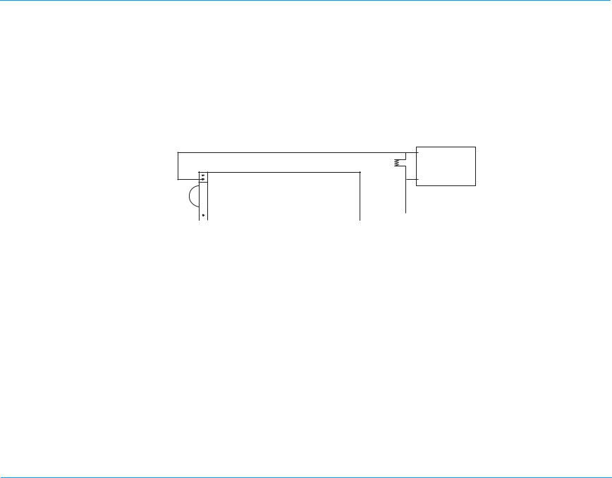
Test Setup: Make sure the unit and power supply are turned off.
Connect one end of the black lead to the “-” terminal in the battery well. Connect the other end of the black lead to the “-” terminal of the power supply. Connect the red lead to “+” terminal socket of the battery well. Use the middle pin with the plastic guard around it.
Connect the other end of the red lead to the “+” terminal of the power supply. Set the power supply voltage to 7V.
CAUTION Be sure to connect the power supply properly to the M Series battery well terminals or damage to the unit may result. Do NOT raise
the power supply voltage above 12V.
resistor (¼W or greater).
¼W or greater).
11
M Series Service Manual
?
Battery Well
15 Amp Supply
?
Red
Black
Do this... Verify that... Pass/
Turn the selector switch to
4.1
MONITOR. (For AED units, turn the selector
switch to ON and select Manual mode.)
Turn the selector switch to the
4.2
OFF position. Adjust the power supply voltage to
4.3
10.3V and turn the selector switch to MONITOR (for AED units, turn the selector switch to the ON position).
Low Battery Test
4.4
Set voltage to 9.8V. Set voltage to 9.4V . The unit displays the LOW BATTER Y message within 30
4.5
Shut Down Voltage Test
4.6
Set voltage to 8.5V.
Record your results on the Maintenance Tests Checklist.
The unit does not turn on.
The unit turns on.
The unit does not display the LOW BATTERY message.
seconds. The unit shuts off within 30 seconds.
Fall
oo
oo
oo
oo
oo
12
M Series Service Manual
Test Setup
Remove red lead from power supply and connect to 0.1ohm resistor. Connect other end of resistor to “+” terminal of power supply using a second red label. Connect multimeter across the resistor. Set voltage scale (if DVM is not autoranging) to 220mV.
Red
Black
+
_
Battery Well
_
+
+
_
DMM
15 Amp Supply
4.7
Do this.... Observe this... Pass/
Fail/
System Current Test Set power supply to 10.3V.
13
M Series Service Manual
Do this.... Observe this... Pass/
4.8
4.9
Record your results on the Maintenance Test Checklist
Turn the selector switch to MONITOR. (For AED units, turn the selector switch to ON and select Manual mode.
Turn unit off.
Voltage across resistor should be 80 mV or less (<800 mA of ON current). Note: Without optional parameters.
a) With green screen or LCD and no options <80mV. b) With yellow screen and no options <81mV. c) With yellow screen and SpO2 <104mV. d) With yellow screen and voice recording <91mV. e) With yellow screen, voice recording, and SpO2
<114mV. f) All devices with EtCO2 <121mV.
Off Current Test
Fail/
oo
oo
Test Setup Remove 0.1 ohm resistor and replace with 1K
Connect DMM across resistor. Set voltage scale to DCV. Measure voltage across resistor.
Measure across resistor with unit
4.10
turned off.
Record your results on the Maintenance Test Checklist
Voltage should be less than 450mV (<450uA of current).
14
oo
M Series Service Manual

5.0 Leakage Current Test

Tools Needed: See the manufacturer’s instructions or supplied specifications for the leakage tester you use.
Test Setup: See the manufacturer’s instructions or supplied specifications for the leakage tester you use. Repeat leakage test with
accessories: MFC, external paddles, and anterior/posterior paddles.
Table 1:
Maximum Leakage Acceptance Limits
Normal Condition Single Fault Condition* ECG 10 50 Universal 100 100 Earth 500 1000
*Single fault considered AC mains on applied part.
15
M Series Service Manual

6.0 Paddles Test (If applicable)

Tools Needed: QED 6 Defibrillator Analyzer .
Test Setup: If applicable, connect the universal cable to the paddles and place the paddles in paddle wells.
6.1
6.2
6.3
6.4
6.5
6.6
Do this... Verify that... Pass/Fail/
Turn the selector switch to
DEFIB (For AED units,turn the selector switch to ON and select Manual mode.) Press
and hold the ENERGY DOWN button on the sternum paddle.
Press and release the ENERGY UP button on the sternum paddle for each setting.
Press and release the RECORDER button on the sternum paddle.
Press and release the RECORDER button again.
Select 30J using the paddle
ENERGY button. Press the CHARGE button on the Apex
paddle.
Press and release the APEX SHOCK button.
The energy selection decreases to 1J.
The joules selection increases as follows: Biphasic 1­10, 15, 20, 30, 50, 75, 100, 120, 150, 200J.
Monophasic (DSW): 1-10,15, 20, 30, 50, 75, 100, 150, 200, 300, 360.
The recorder starts printing.
The recorder stops printing.
The unit charges to 30J, then the red LED charge indicator illuminates and the charge tone sounds.
Note: The front panel shock button does not
illuminate.
The unit does not discharge.
NA
oo
oo
ooo
oo
oo
oo
6.7
6.8
Press and release the STERNUM SHOCK button.
Press and hold both paddles SHOCK buttons.
The unit does not discharge.
The unit discharges. The TEST OK message displays and the red LED turns off. If configured, the recorder prints a strip chart.
16
oo
oo
M Series Service Manual
Do this... Verify that... Pass/Fail/
Record your results on the Maintenance Tests Checklist.
NA
17
M Series Service Manual

7.0 Heart Rate Display Test

Tools Needed: • ECG Cable (3, 5 or 12 leads).
• QED 6 Defibrillator Analyzer.
Test Setup: Turn the selector switch to MONITOR (For AED units, turn the selector switch to ON and select Manual override.)
Press LEAD button until “I” displays. Connect the ECG leads to the QED 6 Defibrillator Analyzer. Connect the ECG cable to the unit.
Do this... Verify that... Pass/Fail/
7.1
Record your results on the Maintenance Tests Checklist.
Set the QED 6 Defibrillator Analyzer to 120BPM.
The Heart Rate displays as 120 +/- 2 bpm.
NA
ooo
18
M Series Service Manual

8.0 Calibrating Pulses on Strip Chart Test

Tools Needed: None
Test Setup: None.
Do this... Verify that... Pass/Fail/
8.1
8.2
Record your results on the Maintenance Tests Checklist.
Press the RECORDER button. Press and hold SIZE button to
activate the calibration signal.
The strip chart displays a signal of 300 ppm with an amplitude of 10 mm +/- 1 mm. The signal also appears on the video display.
NA
ooo
19
M Series Service Manual

9.0 Notch Filter Test

Tools Needed: QED 6 Defibrillator Analyzer.
Test Setup: Connect the ECG cable to the QED 6 Defibrillator Analyzer.
Connect the ECG cable to the unit
Do this... Verify that... Pass/Fail/
9.1
9.2
9.3
9.4
Record your results on the Maintenance Tests Checklist.
Turn the selector switch to MONITOR mode.
(For AED units, turn the selector switch to ON and select Manual mode.)
Select lead I, size 3x. Select 60Hz (or 50 Hz for a 50Hz
unit) on the QED 6 Defibrillator Analyzer.
Press RECORDER button. Verify that the waveform amplitude on the strip chart is
Press RECORDER button to stop printing.
.
less than 1.5 mm.
NA
ooo
20
M Series Service Manual

10.0 Heart Rate Alarm Test

Tools Needed: QED 6 Defibrillator Analyzer
10.1
10.2
10.3
10.4
10.5
10.6
10.7
Do this... Verify that... Pass Fail/
Turn the selector switch to MONITOR mode.
(For AED units, turn the selector switch to ON and select Manual mode.)
Connect the ECG leads to the QED 6 Defibrillator Analyzer the QED 6 Analyzer to 120 BPM
and the defibrillator to lead II. Press ALARMS button. The monitor displays the alarm menu.
Press SELECT PARAM softkey until ECG HR displays.
Press INC> for state. The cursor scrolls through ENABLE, AUTO and
Press DEC>for state. The cursor scrolls through ENABLE, DISABLE, AND
Press INC> until ENABLE displays.
Press ENTER softkey, then press the NEXT FIELD softkey to select the heart rate limit.
. Set
The monitor screen displays the Lead II message and the waveform for NSR ECG at 120 BPM +/- 2 .
The cursor scrolls through parameters.
DISABLE.
AUTO. ENABLE appears.
The cursor scrolls to Low field. Press RETURN softkey to exit out of Alarm Menu.
NA
ooo
ooo ooo
ooo
ooo
ooo
ooo
10.8
Press ALARM SUSPEND button.
No alarm sounds.
21
ooo
M Series Service Manual
10.9
10.10
10.11
10.12
10.13
10.14
Do this... Verify that... Pass Fail/
Remove an EEG lead wire from the QED 6 analyzer.
Reattach ECG Lead wire to the QED 6 Analyzer and hold the ALARM SUSPEND button on unit for 4 seconds.
Press the ALARM SUSPEND button to enable the alarms.
Set QED 6 Analyzer to 160 BPM or higher.
Press the ALARM SUSPEND button on the M Series unit.
Press and hold ALARM SUSPEND for 4 seconds to disable alarms.
The alarm symbol flashes and the heart symbol stops flashing. The ECG LEAD OFF alarm tone sounds. Recorder prints a stripchart showing a low heart rate, if enabled.
The unit displays the alarm symbol with an “X” through it.
The heart symbol flashes with each QRS wave.
The alarm symbol does not have an “X” through it.
The Heart Rate Value is highlighted, the alarm tone sounds, and the alarm and the heart symbol both flash.
The alarm is suspended for 90 seconds. The unit displays the alarm symbol with an “X” through it, and the heart symbol flashes with each QRS wave.
Note: Software version 35.00-36.XX, the alarm is suspended until the alarm button is press again, or the fault is cleared.
NA
ooo
ooo
ooo
ooo
ooo
ooo
Record your results on the Maintenance Tests Checklist.
22
M Series Service Manual

11.0 Defibrillator Self Test

WARNING! SHOCK HAZARD!
TAKE THE NECESSARY PRECAUTIONS TO GUARD AGAINST SHOCK OR INJURY BEFORE YOU START CONDUCTING THE DEFIBRILLATOR TESTS.
Keep hands and all other objects clear of the multi-function cable connections and defibrillator analyzer when discharging the defibrillator.
Before you discharge the defibrillator, warn everyone near the equipment to STAND CLEAR.
CAUTION Do NOT internally discharge the unit more than 3 times in 1 minute. Note that the rapid repetition of internal discharges at
more than 30 Joules may damage the unit.
Tools Needed: • MFC Test Port Connector 1004-0053-99 with universal cable.
• MFC Test Adaptor Connector (Fluke Biomedical Part Number 3010-0378 or equivalent).
• QED 6 Defibrillator Analyzer.
• ECG Cable.
• Stop watch.
Test Setup: Ensure the unit is turned off
Ensure the ECG cable is connected to the unit and analyzer.
23
M Series Service Manual
NOTE: The universal cable should not be connected to any equipment at the beginning of this test.
11.1
11.2
11.3
11.4
11.5
11.6
11.7
Do this... Verify that... Pass/
Turn the selector switch to DEFIB mode.
(For AED units, turn the selector switch to ON and select Manual mode.)
Set leads to PADS. Connect the universal cable to the
MFC test port. Select energy level of 100J and
press the CHARGE button.
Press the SHOCK button. The unit does not discharge. The unit displays the
Set energy level to 30J. The unit discharges internally.
Press the CHARGE button. The unit charges to 30J and displays message, DEFIB
Press and hold SHOCK button. The unit discharges and displays the number of joules
The unit displays the CHECK PADS/POOR PAD CONTACT message.
DEFIB PAD SHORT message displays.
The charge time is greater than 2 seconds and less than 10 seconds and the unit displays the message, SELECT 30J FOR TEST.
message, DEFIB PAD SHORT.
30J READY. The charge ready tone sounds.
delivered and the TEST OK message. For example, the message at the top of the printed strip chart would read as follows: 30 JOULES TEST OK. TEST_CUR=10-14A DEFIB_IMPED=0.
Fail
oo
oo
oo
oo
oo oo
oo
The impedance value may range from 0 to 5 ohms. If configured, the recorder prints a strip chart.
Record your results on the Maintenance Tests Checklist.
24
M Series Service Manual

12.0 Synchronized Cardioversion Test

Tools Needed: QED 6 Defibrillator Analyzer .
Test Setup: Connect the universal cable via the adapter (D.N.I #3010-0378) to the defibrillator analyzer.
Select Sync on analyzer and set ECG on analyzer to 60 -120 BPM.
Do this... Verify that... Pass/
12.1
12.2
12.3
Record your results on the Maintenance Tests Checklist.
Press LEAD button to select PADS and Size X1.
Press the SYNC softkey on the defibrillator. Enter synchronized cardioversion timing test mode on the defibrillator analyzer.
Select 200J (360J for Monophasic units), and then press the
CHARGE button. When the SHOCK button lights, press and
hold the SHOCK button.
Sync markers appear on display.
Note: Sync markers display on the monitor. The sync
marker appears as a down arrow over the ECG R-wave peaks on strip chart and display.
On the analyzer display, the R-wave to shock delay is less than60 milliseconds.
Fail
oo
oo
25
M Series Service Manual

13.0 Shock Test

Tools Needed: QED 6 Defibrillator Analyzer, Stop Watch.
Test Setup: Connect the universal cable via the adapter (D.N.I #3010-0378) to the defibrillator analyzer.
Ensure that a fully charged battery is installed in the unit.
NOTE If your M Series AED does not have manual override capability, do not perform this test.
13.1
13.2
13.3
13.4
13.5
13.6
Do this... Verify that... Pass/Fail/
Turn the selector switch to DEFIB mode.
(For AED units, turn the selector switch to ON and select Manual mode.)
Press the ENERGY SELECT down arrow until 5J displays.
Press the CHARGE button. Wait for the SHOCK button to illuminate.
Press the SHOCK button. The unit discharges 3J-5J into the simulator.
The unit displays DEFIB 5J SEL.
The unit displays DEFIB 5J RDY.
NA
ooo
ooo
ooo
Note: The displayed rhythm may change shape for 30
seconds before it returns to an original rhythm. This is caused by the operation of the adaptive bandwidth defibrillator recovery circuit.)
Press the ENERGY SELECT up arrow until the unit displays 50J.
Press the CHARGE button. Wait for the SHOCK button to illuminate.
The unit displays the message, DEFIB 50J SEL.
The unit displays the message, DEFIB 50J RDY.
ooo
ooo
13.7
Press the SHOCK button. The unit discharges 41J-55J (monophasic 43J-57J)
into the simulator.
26
ooo
M Series Service Manual
13.8
13.9
13.10
13.11
13.12
13.13
13.14
13.15
Do this... Verify that... Pass/Fail/
Press the ENERGY SELECT up arrow until the unit displays 100J.
Press the CHARGE button. Wait for the SHOCK button to illuminate.
Press the SHOCK button. The unit discharges 83J-122J (monophasic 85J-115J)
Press the ENERGY SELECT up arrow until the unit displays 200J.
Press the CHARGE button. Wait for the SHOCK button to illuminate.
Press the SHOCK button. The unit discharges 182J-247J (monophasic 170J-
(Monophasic Units) Press the ENERGY SELECT up arrow unit the unit displays 300J.
Press the CHARGE button. Wait for the SHOCK button to illuminate.
The unit displays the message, DEFIB 100J SEL.
The unit displays the message, DEFIB 100J RDY.
into the simulator. The unit displays the message, DEFIB 200J SEL.
The unit displays the message, DEFIB 200J RDY.
230J) into the simulator. The unit displays the message, DEFIB 300J SEL.
The unit displays the message, DEFIB 300J RDY.
NA
ooo
ooo
ooo
ooo
ooo
ooo
ooo
ooo
13.16
13.17
13.18
13.19
Press the SHOCK button. The unit discharges 255J-345J into the simulator.
(Monophasic Units) Press the ENERGY SELECT up arrow unit the unit displays 360J.
Press the CHARGE button. Wait for the SHOCK button to illuminate.
Press the SHOCK button. The unit discharges 306J-414J into the simulator.
The unit displays the message, DEFIB 360J SEL.
The unit displays the message, DEFIB 360J RDY.
27
ooo ooo
ooo
ooo
M Series Service Manual
13.20
13.21
13.22
13.23
13.24
Do this... Verify that... Pass/Fail/
(Biphasic Units) Press the CHARGE button and start timing with a stopwatch. Stop timing when the SHOCK button lights.
Press the SHOCK button. On the strip chart, the Patient Current is between 20-24
(Monophasic Units) Press the CHARGE button and start timing with a stopwatch. Stop timing when the SHOCK button illuminates.
Press the SHOCK button. On the strip chart, the Patient Current is between 20-24
(AED units only.) Disconnect the universal cable from the analyzer.
The charge time is between 3-6 seconds.
Amps, and the Defib Impedance is between 46-54 Ohms.
Note: This will occur if configured to Auto-Generate Strip s on event.
The charge time is between 4-8 seconds.
Amps, and the Defib Impedance is between 46-54 Ohms.
Note: This will occur if configured to Auto-Generate Strip s on event.
The unit will display CHECK PADS, and give anaudio prompt.if configured for audio.
NA
ooo
ooo
ooo
ooo
ooo
Record your results on the Maintenance Tests Checklist.
28
M Series Service Manual

14.0 Summary Report Test

Tools Needed: QED 6 Defibrillator Analyzer .
Test Setup: Connect the universal cable to the QED 6 analyzer.
If you are using paddles, place the paddles on the analyzer’s discharge plates.
14.1
14.2
14.3
14.4
Do this... Verify that... Pass/
Press and hold the SUMMARY softkey for 4 to 8 seconds to display erase options. Press the ERASE SUMMARY softkey to erase any previously stored data erase any previously stored data.
Set selector switch to DEFIB. Select 200J (360J for Monophasic) using the ENERGY
SELECT button, and press the CHARGE button. When charged,
press the SHOCK button to discharge into the defibrillator analyzer.
Wait 18 seconds, then press the
Code Marker softkey. Press the CPR softkey.
Turn the unit off. Wait 10 seconds and then turn the unit on. Press the SUMMARY softkey, then press the PRINT CHART softkey, then press PRINT ALL.
The unit displays the message, ERASING REPORT.
The unit successfully discharges and prints a strip chart.
The Code Markers appear.
The summary report prints. The report displays the correct date, time, 1 shock delivered and Code Marker event.
Fail
oo
oo
oo
oo
Record your results on the Maintenance Tests Checklist.
29
M Series Service Manual

15.0 Advisory Message Test

Tools Needed: QED 6 Defibrillator Analyzer .
Test Setup: Connect the universal cable via the adapter (D.N.I #3010-0378).
Attach the M Series to the QED 6 Defibrillator Analyzer.
15.1
15.2
15.3
15.4
Do this... Verify that... Pass/
Turn the selector switch to DEFIB mode.
(For AED units, turn the selector switch to ON.)
Select VF (ventricular fibrillation) on the QED 6, then press the ANALYZE button.
Press the SHOCK button. The unit discharges.
Select the NSR (normal sinus rhythm) on the simulator, then press the ANALYZE button.
The unit displays the following messages:
ANALYZING ECG. ST AND CLEAR .* SHOCK ADVISED.* PRESS SHOCK.*+
*AED’s audio prompts are standard. Advisory audio prompts are user configurable.
+If configured for auto charge.
The unit displays the following messages:
ANALYZING ECG. ST AND CLEAR .* NO SHOCK ADVISED.*
*AED’s audio prompts are standard.
Fail
oo
oo oo
Record your results on the Maintenance Tests Checklist.
30
M Series Service Manual
?

16.0 Pacer Test

Tools Needed:
QED 6 Defibrillator Analyzer .
NOTE The following tests are to be performed only on M Series units equipped with the optional pacing function.
The pacer output can be measured using an oscilloscope set to DC coupling connected across a load resistor. (See diagram in column for universal cable connector polarity.) The load resistor is a 100 ohm, 5 watt or greater. The pacer output is a positive going pulse, 40 +/- 2 ms duration with an amplitude of 0.1 volt per milliamp of selected output (e.g., 40 milliamps of selected output has an amplitude of 4 +/- 0.5 volts the specified tolerance displayed on the oscilloscope).
If an external non-invasive pacer analyzer is being used, then follow the manufacturer’s guidelines for measuring the frequency (ppm), output (mA) and the pulse width measured in milliseconds. Note that the analyzer pace load resistor must be less than 250 ohms.
Test Setup: Connect the universal cable from the M Series to the QED 6 Defibrillator Analyzer.
Do this... Verify that... Pass/
16.1
16.2
16.3
16.4
16.5
Turn the Main Selector knob of the unit to Pacer Mode.Set the PACER OUTPUT to 14 mA and disconnect MFC connector from the QED 6 analyzer.
Reconnect the universal cable to
QED 6 analyzer. Press Clear
the Pace Alarm softkey.
Set rate to 180 ppm; output to 0mA.
Increase the output to 40mA. Output on the QED 6 analyzer is 40mA +/- 5mA.
Increase the output to 120mA. Output on the QED 6 analyzer is 120mA +/- 6mA.
The unit displays the CHECK PADS and POOR PAD CONTACT messages displays, and the pace alarm is active.
CHECK PADS and POOR PAD CONTACT message disappears. The pace alarm is cleared.
No output appears on the QED 6 analyzer.
31
Fail
oo
oo
oo
oo oo
M Series Service Manual
16.6
16.7
16.8
16.9
16.10
16.11
16.12
16.13
Do this... Verify that... Pass/
Increase the output to 140mA. Output on the QED 6 analyzer is 140mA +/- 7 mA.
Check the pulse width. Pulse width is 40mS +/-2mS.
Decrease the output to 60mA. Decrease the rate to 30ppm.
Increase the rate to 180ppm. Pacer rate on QED 6 an alyzer is 177-183 ppm.
Connect the ECG cable to the M Series and QED 6 analyzer. Select the ECG at 60 BPM on the QED 6 analyzer.
Press the Async Pace softkey. The unit displays ECG at 60 BPM with stimulu s markers,
Turn off the QED 6 analyzer. Set Pacer Rate to 100ppm. Press the RECORDER ON button.
Press and hold 4:1 button. The unit displays pace stimulus markers every 60 mm+/-
Pacer rate on QED 6 analyzer is 29-31 ppm.
The unit displays ECG at 60 BPM with no stimulus markers.
and displays the Async pace message. The unit displays pace stimulus markers every 15mm +/-
1mm.
1.5 mm.
Fail
oo oo
oo
oo oo
oo
oo
oo
Record your results on the Maintenance Tests Checklist.
32
M Series Service Manual

17.0 SpO2 Monitor Test for SpO2 Option

Tools Needed: • Masimo

Reusable Sensor.
• Masimo Patient Cable
• Fluke Index Series 2 SpO
Test Setup: Connect the universal cable to the MFC test plug.
Simulator.
2
DO NOT connect the ECG cable to the simulator. Connect the Masimo Patient Cable and attach the Masimo sensor to the patient cable. Connect the Masimo sensor to the finger simulation post. Place a fully charged battery into the battery well or connect to ac power (dc power, if equipped). Ensure that the SpO
Do this... Verify that... Pass/
17.1
17.2
Turn the selector switch to MONITOR.
(For AED units, turn the selector switch to ON and select Manual mode.)
Wait ten seconds. Turn on the SpO2 simulator.
Press the SIM softkey on the Index SpO
the MAN softkey.
Simulator is off.
2
Simulator, then press
2
The SpO2 saturation percentage appears as a dashed line on the monitor.
The unit displays the SpO
PULSE SEARCH message.
2
Fail
oo
oo
17.3
Press the 02+ or 02- softkey of the simulator until the SpO2
output is at 98%.
The SpO2 reading of 98 +/- 1% appears on the E Series monitor.
Note: You may need to wait up to 2 minutes for the
information to appear on the ZOLL display.
33
oo
M Series Service Manual
17.4
17.5
17.6
17.7
Do this... Verify that... Pass/
Using the Index SpO2 Simulator, press the BPM+ or BPM- softkey until the heart rate is 230 BPM.
Using the Index SpO2 Simulator, press the BPM- softkey until the
heart rate is 50 BPM.
Using the Index SpO2 Simulator, press the 02+ softkey until the
output is at 72%.
SpO
2
Press Wave 2 softkey. Select the SpO
For CCT units: softkey, and then select SET
TRACE 2, and press Enter. Select SPO2, press Enter.
waveform.
2
Press the Traces
The SpO2 simulator screen displays an SpO2 rate of 230 BPM.
Note that you may need to wait up to 2 minutes for the information to appear on the ZOLL display.
The M Series monitor displays an SpO 100%.
The M Series monitor displays a heart BPM.
The SpO2 simulator screen displays an SpO of 96-100%. The M Series monitor displays a heart rate of 46-54
BPM. The SpO2 simulator screen displays an SpO
of 70-74%. The M Series monitor displays a heart rate of 46-54
BPM. Plethysmographic waveform appears on the ZOLL
display.
saturation of 96-
2
rate of 226-234
saturation
2
saturation
2
Fail
oo
oo oo
oo oo
oo
17.8
17.9
17.10
Press RECORDER. The plethysmographic waveform prints on the strip chart
paper.
Using the Index SpO2 Simulator, press the BPM- softkey until the
heart rate is at 230 BPM.
Remove the Masimo patient cable.
The SpO2 simulator screen displays an SpO rate of 70-74%. The M Series monitor displays a heart rate in the heart
position of 226-234 BPM.
saturation
2
34
oo
oo
M Series Service Manual
Do this... Verify that... Pass/
Record your results on the Maintenance Tests Checklist.
Fail
35
M Series Service Manual

18.0 EtCO2 Monitor Test (for EtCO2 Option)

Tools Needed: Novametrix Capnostat Simulator Tb 1265/7100.
Test Setup: Install the battery
On the Novatrix Simulator, set the folling Set inspired CO Set% CO
to 0
2
Set Sensor Location to ZERO CELL Set Source Current to NORMAL Set CO
mode to CONTINUOUS. Set Temperature to NORMAL
2
Attach simulator to the unit.
to OFF
2
18.1
18.2
18.3
Do this... Verify that... Pass/
Turn the selector switch to MONITOR mode (For AED units, turn the selector switch to ON, and select Manual mode.) Attach the EtCO
Series input connection. Perfom manual zeroing. Press
PARAM softkey, select EtCO press ENTER, and then press
ZERO softkey, then Enter. On the Novametrix SImulator, set
SENSOR LOCATION to AA CELL, set% CO2 to 10% CO2
mode to RESPIRATION.
simulator to the M
2
,
2
SENSO WARMUP message displays.
CO
2
Note: You may need to wait up to 5 minutes for the warm-up message to disappear.
Verify “ZEROING CO2” Adapter” is displayed, then changes to “ZERO DONE” when complete.
Verify the EtCO2 reading of 74-84mmHg appears on the M Series display.
Note that you may need to wait up to 10 seconds for the unit to stabilize.
Fail
oo
oo
oo
36
M Series Service Manual
Do this... Verify that... Pass/
18.4
18.5
18.6
Record your results on the Maintenance Tests Checklist.
On the Novametrix simulator, set% CO2 to 5%.
Press WAVE 2 softkey For CCT units:
softkey, select SET TRACE 2, and press Enter. Select EtCO2, press Enter.
Press the RECORDER button. Verify the EtCO2 waveform prints
Press the Trace
The EtCO2 reading of 34-42mmHg displays on the M Series monitor. The Respiration Rate (RR) of 22-24
displays on the M Series monitor. Note that you may need to wait up to 10 seconds for the
unit to stabilize. Verify the EtCO
Note that the CO2 waveform is displayed and printed at
12.5 millimeters per second scale.
waveform displays.
2
Fail
oo
oo
oo
37
M Series Service Manual

19.0Temperature Test

Tools Needed: IBP Temp Simulator 9100-0402-TF (or equivalent
Test Setup: None
Do this... Verify that... Pass/Fail/
19.1
19.2
19.3
19.4
19.5
Connect the 2-channel Y adapter to the temperature connector (T1/T2) on the M Series CCT Unit.
Connectt the Temperature Probe Simulator cables to the 2-channel Y adapter.
On the Temperature Simulator, set the T1 temperature channel to 59.2 degrees F(15 degrees C).
On the Temperature Simulator, set the T1 temperature channel to 112.8 degrees F (45 degrees C).
On the Temperature Simulator, set the T2 temperature channel to 59.2 degrees F(15 degrees C).
Verify that the value displayed for the T1 temperature channel betwwen 59.0 degrees to 59.4 degrees F (14.9 to 15.1 degrees C).
Verify that the value displayed for the T1 temperature channel betwwen 112.6 degrees to 112.8 degrees F (44.9 to 45.1 degrees C).
Verify that the value displayed for the T2 temperature channel betwwen 59.0 degrees to 59.4 degrees F(14.9 to 15.1 degrees C).
1
)
NA
ooo
ooo
ooo
19.6
Record your results on the Maintenance Test Checklist.
On the Temperature Simulator, set the T2 temperature channel to 112.8 degrees F (45 degrees C).
Verify that the value displayed for the T2 temperature channel betwwen 112.6 degrees to 112.8 degrees F (44.9 to 45.1 degrees C).
ooo
1. If you are using a T emperature Simulator that does have the same setting above, use the closest value available. Verify the display temperature value is within 0.2 F or 0.1 C of the simulator setting
38
M Series Service Manual

20.0 IBP Monitoring Test

Tools Needed: DNI Nevada 214B Patient Simulator with M Series interface cables, FOGG Transducer Simulator
Test Setup: Set the BP output sensitivity scale to 5 uV/V/mmHg on the Patient Simulator
Connect the Patient Simulator to the IBP connector on the M Series CCT unit
20.1
20.2
20.3
20.4
20.5
20.6
20.7
20.8
Do this... Verify that... Pass/Fail/
Set the selector switch on the M Series CCT unit to MONITOR and press the PARAM softkey on the front panel to display the Parameters menu.
Select the IBP option and press the Enter softkey.
Press the Label softkey to display the IBP Label menu.
Select the Label P1 option and press the Enter softkey.
Select the P1 option and press the Enter softkey.
Press the Label softkey to display the IBP Label menu.
Select the Label P2 option and press the Enter softkey.
Select the ART option and press the Enter sofkey.
Verify the parameter menu displayed.
Verify the unit displays the IBP menu.
Verify the unit displays the IBP label menu.
Verify the M Series CCT unit displays the Label Options menu.
Verify the unit assigns the P1 label to the first pressure channel (P1) and returns to the IBP menu.
Verify the unit displays the IBP Label menu.
Verify the M Series CCT unit display the Label Options menu.
Verify the unit assigns the ART label to the second pressure channel (P2) and return to the IBP menu.
Verify that the M Series CCT unit displays advisory messages to zero the pressure channels.
NA
ooo
ooo
ooo
ooo
ooo
ooo
ooo
ooo
ooo
39
M Series Service Manual
20.9
20.10
Do this... Verify that... Pass/Fail/
On the Patient Simulator, set BP channel 1 to an atmospheric pressure of 0 mmHg (waveform
10) and press EXECUTE. Set BP channel 2 to duplicate BP channel 1 (waveform 22) and press EXECUTE.
On the unit go to the IBP menu (press the Param softkey and select the IBP option), then press the Zero softkey to display the Zero menu, select the Zero Both option and press the Enter softkey.
Verify the unit zeroes both pressure channels and displays the P1 ZEROED and P2 ZEROED messages within 15 seconds.
Verify that the values displayed for the P1 and ART pressure channels are accurate within ±3 mmHg of atmospheric pressure (that is, 0 mmHg):
systolic pressure: -3 to 3 mmHg diastolic pressure: -3 to 3 mmHg mean pressure: -3 to 3 mmHg
Note: The unit displays pressure values for each pr essure channel within 15 seconds.
NA
ooo
ooo
20.11
On the Patient Simulator, set to an arterial pressure of 120/80 mmHg (waveform 00) and press EXECUTE.
Verify the values displayed for the P1 and ART pressure channels:
systolic pressure: 1 16 - 124 mmHg diastolic pressure: 77 - 83 mmHg mean pressure: 90 - 98 mmHg
Note: The unit displays pressure values for each pr essure channel within 15 seconds.
40
ooo
M Series Service Manual
20.12
20.13
20.14
20.15
20.16
20.17
20.18
20.19
20.20
Do this... Verify that... Pass/Fail/
Zero the IBP channels (see step
20.9). Press the Traces softkey. Verify the unit displays the Traces menu.
Select the Set Trace 2 option and press the Enter softkey.
Verify the M Series CCT unit displays the Trace Options menu.
Press the Traces softkey. Verify the unit displays the Traces menu.
Select the Set Trace 3 option and press the Enter softkey.
Select the ART option and press the Enter softkey.
Go to the IBP menu (press the Param softkey and select the IBP option).
Press the Range softkey. Verify the unit displays the IBP Range menu.
Verify the M Series CCT unit displays the Trace Options menu.
Verify the unit assigns the P1 waveform to the second trace display area and returns to the main menu.
Verify the unit displays the Trace Options menu.
Verify the unit assigns the ART waveform to the third trace display area and returns to the main menu.
Verify the unit displays the IBP menu.
NA
ooo ooo
ooo
ooo ooo
ooo
ooo
ooo
20.21
20.22
20.23
20.24
20.25
Select the P1 Range option and press the Enter softkey.
Select the 0-30 mmHg option and press the Enter softkey.
Press the Range softkey. Verify the unit displays the IBP Range menu.
Select the ART option and press the Enter softkey.
Select the 0-30 mmHg option and press the Enter softkey.
Verify the unit displays the Range Options menu.
Verify the unit displays the P1 waveform on a 0-30 mmHg scale and returns to the IBP menu.
Verify the unit displays the Range Options menu.
Verify the unit displays the ART waveform on a 0-30 mmHg scale and returns to the IBP menu.
41
ooo
ooo
ooo ooo
ooo
M Series Service Manual
20.26
20.27
20.28
20.29
Do this... Verify that... Pass/Fail/
On the Patient Simulator, set BP channel 1 to a static pressure of 20 mmHg (waveform 11) and press EXECUTE.
Press the RECORDER button. Verify that there is no deviation from the baseline greater
than 1 mm for the waveforms printed on stripchart and the unit displays the waveforms for 20mmHg on the monitor screen, and prints a stripchart of the traces.
Set the input and output resistance to 350 ohms on the Transducer Simulator, and set the gain to x10.
Connect the Transducer Simulator cable to the P1 connector on the unit and on the Pressure Transducer Simulator, set the pressure polarity to positive, and select a pressure of 200 mmHg.
Zero pressure channel 1. Verify the unit calibrates pressure channel 1 against a
positive pressure of 200 mmHg and displays the P1 ZEROED message.
NA
ooo
ooo
20.30
20.31
20.32
On the Pressure Transducer Simulator, set the pressure polarity to positive, and select a pressure of 500 mmHg.
Connect the simulator cable to the P2 connector on the unit. On the Pressure Transducer Simulator, set the pressure polarity to positive, and select a pressure of 200 mmHg.
Zero ART channel. Verify the unit calibrates pressure channel 1 against a
Verify that the value displayed for the P1 pressure channel is in the range of 291 - 300 mmHg. (Note: value will be displayed within 15 seconds.)
positive pressure of 200 mmHg and displays the ART ZEROED message.
42
ooo
ooo
M Series Service Manual
20.33
20.34
20.35
20.36
20.37
Do this... Verify that... Pass/Fail/
On the Pressure Transducer Simulator, set the pressure polarity to positive, and select a pressure of 500 mmHg.
Connect the Pressure Transducer Simulator to the first IBP channel connector (P1). On the Pressure Transducer Simulator, set the pressure polarity to negative, and select a pressure of -200 mmHg.
Zero the pressure channel. The unit calibrates the pressure channel against a
On the Pressure Transducer Simulator, select a negative pressure of -250 mmHg.
Connect the Pressure Transducer Simulator to the second IBP channel connector (P2). On the Pressure Transducer Simulator, set the pressure polarity to negative, and select a pressure of -200 mmHg.
On the unit, verify that the value displayed for the ART P2 pressure channel is in the range of 291 - 300 mmHg. (Note: value will be displayed within 15 seconds.)
negative pressure of -200 mmHg and displays the P1 ZEROED message.
On the unit, verify that the value displayed for the P1 pressure channel is in the range of -47 to -50 mmHg. (Note: value will be displayed within 15 seconds.)
NA
ooo
ooo
ooo
20.38
20.39
Zero the pressure channel. The M Series CCT unit calibrates the pressure channel
against a negative pressure of -200 mmHg and displays the P2 ZEROED message.
On the Pressure Transducer Simulator, select a negative pressure of -250 mmHg.
Verify that the value displayed for the P2 pressure channel is in the range of -47 to -50 mmHg. Note: Value will be displayed within 15 seconds.
43
ooo
ooo
M Series Service Manual

21.0NIBP Transducer Calibration Test

The NIBP module’s pressure transducers are factory-calibrated prior to shipment. However, you can perform a two­point calibration procedure periodically to ensure accurate pressure measurements.
This procedure is optional at 6 months, but should be performed annually or every 10,000 readings, whichever comes first.
Tools Needed: Fluke NIBP simulator (the values and procedure that we provide are specific to the BP Pump 2).
Test Setup: Connect the Analyzer’s simulator hose to the NIBP connector on the M Series unit.
Configure the NIBP Analyzer to simulate cuff pressure. For example, on the Fluke Biomedical BP Pump: Press the MODE button three (3) times to go into Tests mode. Press the SELECT button once to access the Pressure Simulator screen. These instructions apply to the Fluke Biomedical BP Pump; for equivalent devices, follow the manufacturer’s
instructions. Make sure the ECG cable is not connected to the M Series unit. If the SpO2 option is installed, make sure that the Masimo cable is NOT connected to the M Series unit.
21.1
21.2
21.3
Do this... Verify that... Pass/
Turn the Selector Switch to OFF. After 10 seconds, press and hold
the fourth softkey from the left and turn the Selector Switch to MONITOR (for AED units, turn the Selector switch to ON).
. Press the NIBP Calib softkey. The M Series unit displays the NIBP Transducer
On the NIBP simulator set the pressure parameter to 0 mmHg.
The M Series unit powers on in the NIBP Service Mode.
Calibration Screen. The NIBP Simulator displays a pressure reading of 0
mmHg.
44
Fail
o o
oo
oo
M Series Service Manual
21.4
21.5
21.6
21.7
21.8
Do this... Verify that... Pass/
On the M Series unit, press the Set Low softkey to calibrate the
transducer to a 0 mmHg pressure reading.
On the NIBP Simulator, set the pressure parameter to 250 mmHg, and then press Start on the NIBP simulator.
On the M Series unit, press the Set High softkey to calibrate the
transducer to a 250 mmHg pressure reading.
On the NIBP simulator, set the pressure parameter to stimulate a different cuff pressure (for example, 205 mmHg).
On the M Series unit, press the Read Cuff softkey when the
simulator’s Measured screen reaches 205.
The NIBP pressure transducer registers its voltage output at a known pressure of 0 mmHg. The field adjacent to the 0 mmHg value changes to PASS.
Note: If the M Series unit displays a FAIL reading,
verify the NIBP simulator’s pressure setting and connection to the M Series and repeat the step.
The NIBP Simulator displays a pressure reading of 250 mmHg.
The NIBP pressure transducer registers its voltage output at a known pressure of 250 mmHg. The field adjacent to the 250 mmHg value changes to PASS.
Note: If the M Series unit displays a FAIL reading,
verify the NIBP Analyzer’s pressure setting and connection to the M Series and repeat the step.
The NIBP simulator displays the specified pressure reading.
The value that the M Series unit displays is accurate within +/- 3mmHg of the pressure parameter value set on the NIBP simulator.
Fail
oo
oo
oo
oo
oo
21.9
Record your results on the Maintenance Tests Checklist.
On the M Series unit, press the EXIT softkey twice.
The M Series returns to the main NIBP Service Mode screen, then to normal Monitor mode operation.
45
oo
M Series Service Manual
Warning! NIBP transducer calibration can affect clinical readings of the NIBP parameter. Ensure that the NIBP T ransducer Calibration
procedure is performed correctly, followed by an NIBP Monitor Test for verify proper operation.
46
M Series Service Manual

22.0NIBP Monitor Test

The NIBP monitor test verifies the repeatability of the systolic, diastolic, and mean blood pressure measurements, as well as the patient pulse rate calculation.
Tools Needed: Fluke NIBP simulator (the values and procedure that we provide are specific to the BP Pump 2).
Note: The primary propose of an NIBP simulator is to reproduce a pressure profile similar to a live patient to be used for testing th e repeatability the market, each manufacturer uses a different method to develop different simulators may
vary . offset value should then be used to determine the expected values. NIBP simulators cannot be used as a source testing the accuracy of the non-invasive blood pressure measurements of devices such as the ZOLL monitor/defibrillator.
Test Setup: Connect the Analyzer’s simulator hose to the NIBP connector on the M Series unit.
Set the following parameters on the NIBP Analyzer:
Table 1-1:
and
functionality of the system. There are many different NIBP simulators on
their
algorithm. Consequently, readings from
To test for repeatability, you should first establish
2
the
offset
1
of your simulator. The
for
M Series
Parameter Value
Systolic pressure 120 mmHg Diastolic pressure 80 mmHg Mean pressure
Heart pressure 80 bpm
93 mmHg
3
Make sure the ECG cable is not connected to the M Series unit. If the SpO2 option is installed, make sure that the Masimo cable is NOT connected to the M Series unit.
1
NIBP
Simulators may produce a reading on the established based on tance establishing the offset of the simulator and
2
If
you are using the
sure Curve Adjust
3
Not all simulators have a setting of 93mmHg. Check the simulators user's manual for
a
statistical sample of monitors and readings. Please contact ZOLL Technical Support
Fluke®
BiomedicalCuftlink,
Menu.
NIBP
monitor that is shifted from the simulator's setting. The offset value must be
if
you require assis-
test
set-up that you are
you must change the shift value of the Blood Pressure Envelope to +3 on the Pres-
utilizing.
recommendations.
47
M Series Service Manual
Do this... Verify that... Pass/
22.1
22.2
22.3
22.4
Record your results on the Maintenance Tests Checklist.
Turn the selector switch to MONITOR mode.
(For AED units, turn the selector switch to ON and select Manual mode.)
Ensure that the LEADS parameters is set to PADS (default).
If necessary, press the LEADS button to cycle through the values to select PADS.
Press the NIBP button on the E Series front panel.
Press the SUMMARY softkey, then press the TREND softkey, followed by the NIBP Trend softkey.
The M Series unit displays PADS in the Lead selection field on the monitor.
The M Series displays the following measurements:
Systolic pressure (115 - 125 mmHg)
Diastolic pressure (75 - 85 mmHg)
Mean pressure (88 - 98 mmHg).
The M Series unit displays a summary of the NIBP measurements, including the pulse rate reading (in the range of 77 - 83 bpm).
Fail
oo
oo
oo
4
These values only apply for test set-ups utilizing the BP Pump 2 Simulator. V ariations of the test set-up or different simulators may
produce readings Please
contact ZOLL Technical Support i f you
outside
the provided values and will require end-user facility to establish the appropriate offset and tolerances.
require
assistance establishing the offset o f y o u r simulator and test set-up
.
48
M Series Service Manual

23.0NIBP Volume Leak Test with Fluke Biomedical NIBP Analyzer

The volume leak test verifies the integrity of the pneumatic system on the NIBP module. This test is optional at 6 months, but should be performed annually or every 10,000 readings , whichever comes first.
Tools Needed: Fluke NIBP simulator (the values and procedure that we provide are specific to the BP Pump 2).
Test Setup: Connect the Analyzer’s simulator hose to the NIBP connector on the M Series unit.
Configure the NIBP Analyzer for the volume leak test. For example, on the Fluke Biomedical BP Pump:
Press the MODE button three times to go into Tests mode.
Press the SELECT button twice to access the volume leak test.
Make sure the ECG cable is not connected to the M Series unit. If the SpO2 option is installed, make sure that the Masimo cable is NOT connected to the M Series unit.
23.1
23.2
23.3
23.4
Do this... Verify that... Pass/
Turn the Selector Switch to OFF. After 10 seconds, press and hold
the fourth softkey from the left and turn the Selector Switch to MONITOR (For AED units, turn the selector switch to ON).
Press the Leak Test softkey. The M Series unit displays the NIBP Le ak Test Screen.
On the NIBP simulator, set the pressure parameter to 200 mmHg.
On the M Series unit, press the Close Valves softkey .
The M Series unit powers on in the NIBP Service Mode.
The NIBP simulator displays a pressure reading of 200 mmHg.
The Valves status changes from OPEN to CLOSED.
49
Fail
oo
oo oo
oo
M Series Service Manual
Do this... Verify that... Pass/
23.5
Press the START TEST softkey within 30 seconds after closing the valve.
Note: This test takes
approximately 3 minutes.
23.6
23.7
Record your results on the Maintenance Tests Checklist.
On the NIBP Analyzer, press the STOP TEST softkey.
On the M Series unit, press the EXIT softkey twice.
After approximately 1 minutes, a number appears in the upper middle area of the NIBP simulator display.
If the simulator:
Displays a Volume Leak reading <5, Series unit has passed the test.
Displays a Volume Leak reading >5, Series unit has failed the test.
Displays no Volume Leak reading, but maintains a
stable pressure reading at or above 200 mmHg, then the M Series unit has passed the test; there is no volume leak.
In addition, the M Series unit displays the simulator’s pressure reading in the “Cuff Pressure” field.
After approximately 3 minutes, the valves open on the M
Series unit.
The NIBP simulator terminates the Volume Leak Test.
The M Series unit returns to the main NIBP Service Mode screen, then to normal Monitor mode operation.
5
then the M
6
then the M
Fail
oo
oo
oo
5
you are using the Fluke®
If
6
If
you are using the Fluke®
BiomedicalCuftllnk Simulator,the volume BiomedicalCuftllnk
Simulator,the volume
50
leak reading leak reading for a failure
should
be
<10.
should
be
>10.
M Series Service Manual

24.0 Bluetooth Test

Tools Needed: USB Bluetooth dongle with driver CD, Bluetooth application software BlueSoleil.
Test Setup: Verify that the M Series unit is configured as follows: Bluetooth INSTALLED, and Baud Rate set to 115200 or 38400.
24.1
24.2
24.3
24.4
24.5
Do this... Verify that... Pass/
Power up the M Series unit while pressing in and holding the left­most softkey.
Insert a PCMCIA card containing data into the card reader.
Press the UPLOAD CARD softkey, then press the softkey UPLOAD CARD.
Press the SEND softkey.
Double click on the HyperT erminal shortcut (BT115200) from the desktop.
The M Series unit displays the System Utilities Menu.
Verify that the Bluetooth LED is on and displays a green light.
Fail
oo
oo
Note: If setting up Hyperterminal
for the first time set COM PORT programmed for Bluetooth adapter, 1 15200bp s, 8, N, 1, N
24.6
24.7
Start Bluetooth Utility software (Blue Soleil) on the computer.
In the IVT Corporation Blue Soleil window under “View”, select refresh devices.
51
M Series Service Manual
Do this... Verify that... Pass/
24.8
24.9
Record your results on the Maintenance Tests Checklist.
Find the unit under test Serial Number and double click on it.
Click on the Serial Port Icon that is highlighted at the bottom of the window
Verify the following: At the bottom of the window it states Connected, The file transfer window pops up and the file upload
progress bar goes to 100%. The unit displays the file upload message, Card
Uploaded.
Fail
oo oo
oo
52
M Series Service Manual

Overview

This chapter describes the most common technical problems that biomedical technicians experience when checking the M Series during routine maintenance or when there is a malfunction of the unit. It also contains a list of error messages that users may see if the unit is not operating properly.
This chapter contains the following:
• Troubleshooting tables for ECG Leads Off Messages and Monitor Displays
• Zoll M Series Error Messages
Chapter 2

Troubleshooting

If the problems you encounter are not listed below, call ZOLL Medical Corporation’s Technical Service Department for further assistance. (See page vii for contact information.)
53
M Series Service Manual

Troubleshooting

The following tables show the most common troubleshooting issues and their solutions. First, attempt to solve the problem with “Recommended User Action.” If these steps do not solve the problem, follow
the steps listed in the “Recommended Technical Action” column.
Reported Problem Recommended User Action Recommended Technical Action
ECG LEAD OFF message displays. (3, 5, 12 lead cable)
Check preparation of ECG electrode site by
cleaning the site, lightly abrading the patient’s skin and/or clipping the patient’s hair at the electrode site.
If electrode gels are dry, replace electrodes with
new ones from a freshly opened package.
Verify that all leads are attached.
Set monitor to another lead.
Verify that the electrodes have not exceeded their
expiration date.
T ry to reproduce the problem using
a simulator.
Inspect the ECG cables looking for
corrosion or broken connector pins.
Check the cable for intermittent
connections by flexing the cable at the yoke and snap connectors.
Check the cable connection to the
defibrillator.
Inspect the ECG input connector
and its pins. Replace it, if necessary.
Inspect the ECG cable connection
to the system board.
Inspect the system board ECG
shielding.
Remove and replace the system
board.
54
M Series Service Manual
Reported Problem Recommended User Action Recommended Technical Action
V LEADS OFF message displays.
CHECK P ADS/POOR PAD CONTACT message displays.
If the user is not using V leads, attach V lead
connector terminator plug to the cable’s V lead connector.
If a V1 lead wire metal snap comes in contact with
the patient’s skin, then the system will show all V leads as OFF.
Remove V1 leads and others away from the
patient. Turn off the unit and wait ten seconds before turning it back on.
Remove and reinsert PADS connector into the
universal cable.
Check for damaged defibrillator pads, wires and or
connector.
Check for dried out or expired defibrillator pads.
Clip (not shave) the patient’s hair and wipe pad
contact area dry.
Connec t the cable to the test plug. The DEFIB PAD
SHORT message displays to indicate that the cable is functioning properly.
If the DEFIB PAD SHOR T message displays, then
check the connections of the pads to the patient and to the defibrillator cable.
If the DEFIB PAD SHORT message does not
display, remove the defibrillator from service.
Connect universal cable to the
shorting plug. The DEFIB PAD SHORT message should display, when you SELECT PADS. If the message does not display , then:
Try another universal cable.
Chec k the cable from the universal
cable connector to the High Voltage Module.
Chec k the cable from the High
Voltage Module to the system board.
Remove and replace the High
Voltage Module.
Remove and replace the system
board.
Call ZOLL Technical Support for
assistance.
55
M Series Service Manual
Reported Problem Recommended User Action Recommended Technical Action
Flash or arcing under defibrillator pad.
Displayed HR not accurate. No artifact present.
Avoiding using alcohol and betadine in and around
the treatment area because these skin preparations may lead to increased conductivity and/or bonding between the electrode’s adhesive and skin.
Check for ge l droop. If the gel has leaked out of the
gel treatment area, replace the electrode.
Ensure pads are coupling to the patient’s skin and
connected to the universal cable.
Check for dried out gel on the defibrillator pad.
Clip patient’s excessive hair. Do not shave hair.
Check expiration date. Replace pad if date has
expired.
Do not conduct chest compression through the
pads because the pads could be damaged leading to the possibility of arcing and skin burns.
Apply the back electrode first. If the front electrode
is already in place when the patient is being maneuvered for placement on the back, the front may become partially lifted, possibly causing arching and skin burns.
Verify heart rate flashes with each QRS on display.
Change lead selection.
Change ECG size.
Reposition ECG electrodes.
Ensure that wet gel pads are stored
flat.
56
M Series Service Manual
Reported Problem Recommended User Action Recommended Technical Action
Displayed HR not accurate; artifact present.
Reduce or eliminate ECG artifact due to
electrode or patient cable movement. Route cables so that they don’t pull on electrodes or swing excessively .
Ensure patient is motionless.
Check for possible excessive radio frequency
interference.
Verify a good connection of electrod es to the
patient.
Prepare the patient’s skin prior to the electrode
attachment.
Move patient cables away from other electrical
equipment, especially any RFI source.
Ensure ECG cable fits snugly in unit.
Change ECG cable.
Replace/reposition ECG electrodes.
Wandering baseline. See “Displayed HR not accurate.” above. Note that
in 90% of electrode issues, size and lead changes don’t help.
Electronic interference. Check for possible excessive radio frequency
interference. Move patient cables away from other electrical equipment.
Chec k for contamination on snaps.
Ensure springs are intact.
Check for intermittent ECG patient
cable or connector wiring.
Replace ECG input connector.
Replace ECG connector to the
system board cable.
Replace system board.
Same as above example.
Turn off sources of excessive RFI.
Move M Series unit away from
RFI source.
57
M Series Service Manual

Zoll M Series Error Messages

The following is a list of Zoll M Series error messages that may appear on your display. The “User Advisory” column informs you about an action in progress or provides feedback on a user correctable situation that typically does not require further technical support. The “T echnical Action” column describes what you as a technician can do to correct the situation. Note that these messages will sometimes overlap part of the waveform display.
First, attempt to clear the message by turning the Selector Switch to OFF for ten seconds, then back to the desired operating mode. If the fault persists, call ZOLL Technical Service.
Error Message Explanation
200J MAX BIPHASIC User attempted to set defibrillation energy >200J on
Biphasic Unit. No higher energy is available.
50J MAX Energy < 50J for internal paddles. No higher energy
is available.
ADJUST ECG Unit is in sync mode and heart rate is < 20 BPM.
Or, QRS size set too small for proper synchronization.
ANALYSIS HALTED ECG analysis halted due to user interaction such
as:
Lead/size change
Analyze button was pressed again
Impedance fault
Charging error detected in auto defib mode
ANALYSIS RESTARTED This is a user prompt issued simultaneously with
ECG TOO LARGE or ECG TOO SMALL. Device detected ECG signals out of range, automatically adjusted ECG size and is now restarting its shockable rhythm analysis sequence.
User Advisory
Technical Action
58
M Series Service Manual
Error Message Explanation
AUDIO FAULT 136 Audio DSP hard ware error. Replace audio board.
AUDIO NOT RECORDING
AUDIO QUEUE FULL Indicates that the audio out put queue is full.
BATT HIGH CURRENT Battery is charged and battery current is >.1 A or:
BATT HIGH VOLTAGE Battery voltage > 15.5 v. Replace battery and or
Audio is not recording. Install PCMCIA card.
Additional voice prompts can't be queued at this time.
Battery is not charged and battery current is > 1.6 A.
User Advisory
Technical Action
Replace system board.Turn unit off and back on again.
Replace system board. None.
Unplug from A/C. Remove the battery for 20 seconds. Reconnect all above. If the problem persists, replace battery and or charger.
charger
BATT LOW CURRENT Battery is not charged and battery current is <.35 A. Replace battery and or
charger.
BATT LOW VOLTAGE Battery voltage < 9.5 v. Replace battery and or
charger.
BATT OVERCHARGE Charger on for > 4 hours. Replace battery and or
charger.
59
M Series Service Manual
Error Message Explanation
BRIDGE SHORT Current higher than expected was detected during the
Biphasic bridge test or immediately following a discharge.
BRIDGE TEST FAILED Biphasic modul e not operating properly while
charging.
User Advisory
Technical Action
Ensure pads/paddles are used properly .
Attempt to clear the message by turning the Selector switch to off then back to the desired operating modes.
Replace bridge or high voltage module.
Charge again.
Attempt to clear the message by turning the Selector switch to OFF , then back to the desired operating mode.
Replace bridge or high voltage module.
CABLE FAULT (Auto defib mode only.)
Incorrect A/D reading for paddle ID (similar to PADDLE FAULT).
CANNOT CHARGE Cannot charge when charge button pressed. Replace high voltage
REPLACE CARD Write errors during manual or semi-automated
modes.
60
Replace paddle set, universal cable and/or system board.
module or capacitor. May have configuration
card installed or write protection on.
M Series Service Manual
Error Message Explanation
CARD FULL Memory Card Full. CHECK CO2 SENSOR EtCO2 Sensor is unplugged or defective.
CHECK CO
CHECK MEMORY CARD No card detected during manual or semi-automated
CHECK PADS Message displayed in conjunction with either POOR
ADAPTER Airway adapter is removed, occluded or adapter
2
zeroing needs to be performed or was performed incorrectly.
modes.
PAD CONTACT or DEFIB PAD SHORT.
User Advisory
Technical Action
Check that sensor cable is plugged in and seated properly. Check that sensor is not exposed to excessive heat. If problem persists, replace the sensor.
Replace/Clean airway adapter. Zeroing performed automatically.
Ensure pads are coupled to patient. Check /replace pads and universal cable. Replace system board.
CHECK PATIENT Background ECG analysis detects shockable rhythm. CHECK PULSE Alternate message for NO SHOCK ADVISED
message.Message also shown after delivering third shock when auto analyze 3 times option is enabled.
CHECK RECORDER Produced when paper tray is empty, paper jams or
recorder door is opened.
61
Replace paper sensor board, system interconnect board, and/or system board.
M Series Service Manual
Error Message Explanation
CHECK SPO2 SITE Low or no perfusion in monitored finger or toe. CHECK SPO2 SENSOR Reposition SpO2 sensor on patient. CLOCK FAULT 11 Real time clock oscillator failure. Replace system board.
CLOCK FAULT 12 Real time clock back-up power supply failure. Found
oscillator stopped at power-up, but oscillator now running when the system is running. (Oscillator only runs when main power is applied).
CLOCK FAULT 13 One of the set time units (seconds, minutes, year,
etc.) is out of range.
COMM ERROR No or invalid communication from the EtCO
CO
2
module.
SENSOR WARM UP EtCO2 Sensor warming up.
CO
2
CONFIRM MANUAL MODE
Displayed when manual mode is entered. Alerts user to confirm that manual mode is desired.
2
User Advisory
Technical Action
Replace system board.
Replace EtCO and or system board.
W ait for sensor to warm up. This process takes up to approximately one minute.
module
2
DEFIB DISABLED User prompt issued simultaneously with other faults
if defib is disabled.
DEFIB FAULT 71 More than 50 internal dumps occurred in less than 20
minutes.
62
Possible configuration problem. Replace high voltage module. Call ZOLL Technical Support.
Turn the unit to OFF and back on. If fault persists, replace high voltage module.
M Series Service Manual
Error Message Explanation
DEFIB FAULT 72 General defib error. Turn the unit to OFF
DEFIB FAULT 76 Capacitor voltage too high for selected energy. Replace high voltage
DEFIB FAULT 77 Capacitor voltage > than absolute rated max. Replace high voltage
DEFIB FAULT 78 Unable to charge defib cap. Replace high voltage
DEFIB FAULT 79 Defibrillator charging too slowly. Replace high voltage
DEFIB FAULT 80 4 defibrillator faults detected within 20 second
period.
DEFIB FAULT 81 Discharge switch in undefined state. Replace high voltage
User Advisory
Technical Action
and back on. If fault persists, replace high voltage module.
module or capacitor.
module or capacitor. Replace high voltage
module or capacitor.
DEFIB FAULT 84 “Upper” discharge transistor shorted (measured via
applicable A/D channel).
DEFIB FAULT 85 “Lower” discharge transistor shorted (measured via
applicable A/D channel).
DEFIB FAULT 86 One discharge switch closed during power up test. Replace paddles,
DEFIB FAULT 87 Both discharge switches closed during power up test. Replace paddles,
63
Replace high voltage module.
control board or system board.
M Series Service Manual
Error Message Explanation
DEFIB FAULT 94 Processor fault causing safety monitor port to be
non-functional.
DEFIB FAULT 95 Safe or shutdown line is not functional. Replace high voltage
DEFIB FAULT 96 XPATREL or XPAT_ENABLE is faulted or one of
the discharge transistors has shorted.
DEFIB FAULT 108 VMON voltage is less than the target energy during
charging.
DEFIB FAULT 109 Defib capacitor voltage is greater than selected
energy when defibrillator is charging or ready.
DEFIB FAULT 111 Defib capacitor voltage has exceeded the absolute
maximum acceptable voltage.
DEFIB NOT CHARGED Discharge button is pressed but the unit is not
charged.
User Advisory
Technical Action
Replace system board, high voltage module or capacitor.
module. Replace high voltage
module or capacitor. Replace high voltage
module, capacitor, and or system board.
DEFIB PAD SHORT Measured impedance between high voltage leads of
MFC.
DISABLE SYNC Sync mode active when analyze pressed in defib. DISCHARGE FAULT Defib capacitor voltage is not decreasing. Replace high voltage
64
Ensure pads are coupled to patient. Check /replace pads or universal cable. Replace system board.
module, capacitor, and/ or system board.
M Series Service Manual
Error Message Explanation
ECG FAULT 4 Communication fault between ECG processo r and
main processor.
ECG FAULT 5 ECU RAM test failure, or ROM checksum test
failure.
ECG LEAD OFF One or more ECG leads are not properly connected
when leads are selected as input.
ECG TOO LARGE ECG signal too large for accurate shockable rhythm
analysis.
ECG TOO SMALL ECG signal too small for accurate shockable rhythm
analysis.
ECG V1 LEAD OFF Chest lead V1 is not properly att ach ed to pati ent.
User Advisory
Technical Action
Turn off unit and then turn on to reset. If fault persists, replace system board.
Check cable and patient connection. Change electrodes. Prepare patient’s skin.
Reduce ECG size.
Increase ECG size.
Reattach V lead. Check cable.
ECG V2 LEAD OFF Chest lead V2 is not properly att ach ed to pati ent.
ECG V3 LEAD OFF Chest lead V3 is not properly att ach ed to pati ent.
ECG V4 LEAD OFF Chest lead V4 is not properly att ach ed to pati ent.
ECG V5 LEAD OFF Chest lead V5 is not properly att ach ed to pati ent.
65
Reattach V lead. Check cable.
M Series Service Manual
Error Message Explanation
ECG V6 LEAD OFF Chest lead V6 is not properly att ach ed to pati ent.
ENTER ACCESS CODE Manual mode access code needed.
ERASING REPORT Summary report being erased. ECU CRC FAULT Invalid ECG samples detected over a one second
period.
EtCO2 COM ERROR No or invalid communication from EtCO2 module. Return unit for service
FAX DIALING Preparation for sending fax. FAX DONE Transmission complete. FAX PREPARING Preparing fax for transmission.
User Advisory
Technical Action
Reattach V lead. Check cable.
Enter access code to enter manual mode with AED.
Turn off unit and then turn on to reset. If fault persists, replace system board.
to ZOLL Technical Service Department.
FAX SENDING Transmitting fax. INSERT CARD
Check memory card LOW BATTERY Low battery.
NO QRS DETECT Unit is in sync mode and heart rate is < 20 BPM or
No card installed in unit during manual or semi­automated modes.
QRS amplitude is too low for proper synchronization.
66
Replace battery or plug into AC power. Replace charger.
Increase ECG size and/ or change lead.
M Series Service Manual
Error Message Explanation
NO SHOCK ADV No shock advised. Advisory message when analysis
finds non-shockable rhythm.
NOISY ECG Number of noisy analysis intervals exceeds
threshold.
OPEN AIR DISCHARGE Cap voltage too high after discharge attempt, e.g.,
full energy discharge did not occur.
PACER DISABLED User prompt issued simultaneously with other pace
faults if pacing is disabled.
PACER FAULT 115 Flyback pulse width cont rol circuit is not under
proper control of the processor and gate array.
PACER FAULT 116 Failure to detect XPACE_ON. Replace high voltage
User Advisory
Technical Action
Stop all patient movement. Check connections. Press Analyze button again.
Replace paddles, and, or high voltage module and system board.
Replace high voltage module or system board.
Replace high voltage module, capacitor, or system board.
module, capacitor, and/ or system board.
PACER FAULT 117 Pace relay is stuck closed. Replace high voltage
module, capacitor, and/ or system board.
PACER FAULT 121 During pace, the pace pulse width <30ms or >50ms. Replace high voltage
module, or system board.
PACER FAULT 122 Pace current is more than 15mA above and below
selected value.
67
Replace high voltage module, or system board.
M Series Service Manual
Error Message Explanation
PACER FAULT 123 Measured pace rate is too fast compared to selected
rate.
PACER FAULT 126 Issued in conjunction with message 122. Pace
current is more than 15mA and below selected value.
PADDLE FAULT Cannot detect type of accessory attached to the
universal cable.
PERFORM CPR Advisory message in AED auto defib mode. PLACE ON ZERO CELL EtCO2 sensor cable plugged into unit for the first
time. Zeroing error or probe drift error detected.
POOR LEAD CONTACT One or more ECG leads are poorly connected or not
connected to patient. (User configurable.)
User Advisory
Technical Action
Replace high voltage module or system board.
Replace high voltage module.
Replace paddles, internal paddles, system board, high voltage module and/or universal cable.
Zero sensor. Replace sensor. Return to ZOLL for service.
Check electrode attachment to patient, cable connector to electrode, cable to unit connector. Broken unit.
POOR PAD CONTACT Electrode impedance exceeds threshold. Ensure pads are
coupled to patient. Check /replace pads or universal cable. Check impedance circuit calibration. Replace system board.
PRESS ANALYZE Alternate message for check patient prompt.
68
M Series Service Manual
Error Message Explanation
PRESS CHARGE Advisory message in conjunction with shock
advised.
PRESS SHOCK Prompt issued in AED auto defib mode when defib is
charged (ready).
RECORDER FAULT 142 Strip chart system error. Check paper tray and
RECORDER FAULT 143 Strip chart failed power-up echo test.
Communications error.
RECORDER FAULT 147 Strip chart printhead over temperature. Check paper tray and
User Advisory
Technical Action
paper path. Replace the print head, system interconnect board and or the system board.
Check paper tray and paper path. Replace the system interconnect board and/or the system board. Turn unit off and back on again.
paper path. Replace the print head, system interconnect board and/ or the system board.
RELEASE BUTTONS Simultaneous external paddle button presses
detected before unit reached full defib charge (ready state).
RELEASE SHOCK Discharge switch(es) closed when pressing charge
button. Discharge button pressed before defib reached ready state.
REPLACE BATTERY Battery voltage is less than absolute minimum.
Shutdown imminent.
69
Release buttons.
Release shock button. Check paddles. Replace controls board.
Replace with charged battery.
M Series Service Manual
Error Message Explanation
REPLACE EtCO SENSOR
REPORT FULL Summary report memory full. REPORT HALTED Summary report stops printing unexpectedly. Turn unit off and then
RESERVED 1 The watchdog timer is not functional in the unit. Turn off unit and then
RETRY ANALYSIS Advisory message in conjunction with noisy ECG.
SELECT 30J FOR TEST Attempt to run a self test at an energy other than 30J. SELECT DEFIB MODE Analyze button pressed in pace or monitor mode.
2
SENSOR WARM UP message displays for
EtC0
2
more than five minutes. Sensor defective.
Analysis halted.
User Advisory
Technical Action
Replace sensor cable.
Erase summary report.
back on again. Print Summary again. If fault persists, replace system board.
turn on to reset. If fault persists, replace system board.
SELECT LIMB LEADS Paddles or augmented ECG leads selected when
continuous analysis active or started.
SELECT PADS Lead I, II, or III selected when analyze pressed. SET CLOCK Real time clock failure: invalid date or time. Set date and time and/
SET PACE mA Multiple copy errors are the product of intended
software or memory errors. If error reoccurs other than on entering pace the first time or after more than 10 minutes in other mode, the unit could be broken.
70
Select limb leads I, II, III or MFE
or replace system board.
Set pace current. If broken, replace system board.
M Series Service Manual
Error Message Explanation
SET PACE RATE Multiple copy errors are the product of intended
software or memory errors. Multiple copies of pace rate don't match. If error persists, unit could be broken
SHOCK ADVISED Advisory message when analysis finds a shockable
rhythm.
SpO2 AMBIENT LIGHT Ambient light is too bright. Shield sensor from
SpO2 COMM ERR No transmissions from SpO2unit received.
Communication error or no communication from Sp0
module.
2
SpO2 PULSE SEARCH Pulse search in progress. SpO2 SENSOR F AULT 1 Defective sensor. Replace Sp02 sensor.
User Advisory
Technical Action
Set pace rate. If broken, replace system board.
ambient light. Replace Sp0
sensor. Replace
2
module
Sp0
2
Replace Sp02 module and/or system board.
SpO2 SENSOR FAULT 5 Unrecognized sensor. Replace Sp02 sensor.
STAND CLEAR (Auto defib mode only.) Single analysis mod e ju st
turned on and defib idle. Patient rhythm is being analyzed.
SYSTEM FAULT 2 MCU ROM checksum test failure or MCU RAM test
failure.
71
Turn off unit and then turn on to reset. If fault persists, replace system board.
M Series Service Manual
Error Message Explanation
SYSTEM FAULT 5 ECU RAM test failure or ROM checksum test
failure.
SYSTEM FAULT 6 No communications received from ECU for 4
seconds.
SYSTEM FAULT 7 The A/D converter is not performing conversions in
a timely manner.
SYSTEM FAULT 36 P1MON is less than 412 counts or greater than 612
A/D counts. Pace/defib is disabled as long as
condition exits. SYSTEM FAULT 37 Disable pace/defib and MFE monitoring. Replace system board. SYSTEM FAULT 38 Failure to shutdown after “shutdown order” is
written to the RTC. TEST FAILED MCU performed ipeak test (defib peak current) and
unit failed during 30J self test.
User Advisory
Technical Action
Turn off unit and then turn on to reset. If fault persists, replace system board.
Replace system board.
Replace universal cable, paddles or high voltage module, capacitor, or system board.
TEST OK MCU performed ipeak test (defib peak current) and
unit passed 30J self test. USE PADDLE DISCHG Front Panel discharge button is pressed when either
external paddles or internal spoons with discharge
buttons are connected.
72
M Series Service Manual
Error Message Explanation
USE PADS (AUTO DEFIB MODE ONLY.)
Attempt to defib with paddles in auto defib (AED)
mode. Defib only allowed using PADS in AED
modes. USE PADS TO PACE External paddles detected in pace mode.
USE ROOM AIR ADAPTER
USER SETUP REQ Both copies of stored cal/config data are bad or have
VF ALARMS OFF VF alarms disabled in pace mode or when paddles
VX LEADS OFF V lead not properly attached to patient. “X” denotes
ZERO CO ZERO CO
SENSOR New EtCO2 sensor needs to be zero calibrated.
2
ADAPTER New EtCO2 airway adapter needs to be zero
2
Adapter zeroing started with EtCO2 in the adapter or
the adapter is on the REF or “0” cell.
never been programmed.
are selected as leads.
lead number.
calibrated.
User Advisory
Technical Action
Place CO2 sensor on adapter in room air.
Perform configuration setup.
Reattach V lead.
Zero EtCO2 sensor. Zero EtCO2 adapter.
73
M Series Service Manual
74
M Series Service Manual

Overview

This chapter provides instructions on how to disassemble and reassemble the M Series unit, and includes the following sections:
• Required Equipment
• Parts That May Need Replacing After Disassembly
• Safety Precautions
• Overview of Modules
• 1. Removing the ZIF Keeper
Chapter 3

Disassembly Procedures

• 2. Removing the Front Panel
• 2A. Removing the Display
• 2B. Removing the Control Board
• 3. Removing the Upper Housing Assembly
• 4. Removing the System Board Assembly
• 5. Removing the Battery Interconnect Board Assembly
• 6. Removing the High Voltage/Charger Assembly
• 7. Removing the High Voltage Module Assembly
• 8. Removing the High Voltage Capacitor Assembly
• 9. Removing the System Interconnect Board
• 10. Removing the Printer/Recorder Motor
• 11. Removing the Lower Housing Assembly
• 12. Removing the Print Head Assembly
75
M Series Service Manual
• 13. Removing the PCMCIA Card Slot Assembly
• 14. Removing the Paddle Release Latch

Required Equipment

• No. 1 Phillips screwdriver.
• No. 2 Phillips screwdriver.
• Exacto-knife.
• Orange wooden stick. (Available from H.A. Stiles: 1-800-447-8537)
• 90° dental pick.
• Needle nose pliers.
• Kapton tape.
• 3M copper adhesive tape, or equivalent.
• 1/2” nut driver.
• Lar ge diagonal cutters.
• Strong glue, such as Loctite 420 or equivalent.
• Loctite needle tip dispenser.

Parts That May Need Replacing After Disassembly

If you are removing the Control Board from the Front Panel, you need to have :
• Main Selector knob replacement (ZOLL Part Number 9310-0521)
• Pacer/Output/Rate knob replacement (ZOLL Part Number 9310-0520)
If you are removing the Battery Interconnect Board, you may need to replace it with a new one, using ZOLL Part Number 9301-0302, if connectors have been UV welded as in older M Series models.
76
M Series Service Manual

Safety Precautions

WARNING! SHOCK HAZARD!
CAUTION TAKE THE NECESSARY PRECAUTIONS TO GUARD AGAINST SHOCK OR INJURY BEFORE YOU CONDUCT
DEFIBRILLATOR TESTS OR REPAIRS.
• Only properly trained technicians should service the unit.
• The unit can contain deadly voltages even if the unit is turned off.
• Make sure to discharge the unit before working with it.
• Make sure you take the necessary precautions when working with static sensitive units. For example, you must wear a conductive wrist strap (which touches your skin) connected to a grounding mat and to the earth ground. Y ou must remove the wrist strap when you discharge high voltage or when you are working on energized equipment.
77
M Series Service Manual

Overview of Modules

The M Series unit contains 14 modules, as shown below.
Isolated Power Supply with EtCO
System Interconnect Board Battery Interconnect Board Assembly with 3 Battery
2
SpO2 module with bracket for EtCO
Pin Gaskets
2
System Board Assembly
AC Charger Assembly
78
M Series Service Manual
Control Board (from Front Panel) High Voltage Module Assembly High Voltage Capacitor Assembly
PCMCIA Card Slot Recorder Motor SpO
Isolated Power Supply for SpO
Module Biphasic Capacitor and Bridge Assembly
2
79
Module (without bracket)
2
M Series Service Manual
80
M Series Service Manual
Latch
Lift here
Latch
Keeper

1. Removing the ZIF Keeper

Tools Required
• Orange stick
Note: It is important to know this procedure before you start disassembling the unit. Removing the ZIF (Zero Insertion Force) Keeper incorrectly can damage the unit’s system board.
To reinstall the ZIF Keeper:
1. Place the ZIF Keeper over the laminate cable and insert the flex cable into the connector. Latch the connector.
Step 1: The connector must be facing you as shown in the diagram.
Step 2: Angle and lift up the right end of the ZIF Keeper from the connector and the board. Slide the Keeper approximately 1 mm to the left, then gently lift the left side to clear the connector.
Step 3: Gently pull the ZIF (Zero Insertion Force) Keeper over the laminate cable and rotate the latch upwards.
2. Lower the left end of the ZIF Keeper over the connector end until it touches the printed wire assembly (PWBA). The other end of the connector should be angled.
3. Press the end of the ZIF Keeper down over the end of the connector. Be careful that the ZIF Keeper snaps over the end of the connector.
81
M Series Service Manual
Multi-wire cable

2. Removing the Front Panel

Tools Required
• No. 2 Phillips screwdriver
• Orange stick
To reinstall the Front Panel:
1. Reinstall the laminate cable first with the black band facing up and towards the system circuit board.
2. Reconnect the multi-wire cable from the display.
3. Reverse steps 1, 2, and 3 above to reinstall the front panel.
Step 1: Remove the battery from the battery well and place it in front of the unit.
Step 3: Place your thumbs in the main selector switch cup and push up on the front panel to release the panel from the unit. After the front panel is removed, use the battery as a support for the panel. Do not use the main selector switch as
point of leverage.
Step 2: Rotate unit on to its back side. Remove
the two Phillips head screws located on the left and right sides on the bottom of the unit.
Step 4: Disconnect the multi-wire cable from the system board by gently pulling the beige connector by its sides towards the front of the unit. Remove the ZIF keeper from the laminated ribbon cable and then disconnect it. Lift the right side first with the unit facing you.
82
M Series Service Manual
video display assembly
2A.

Removing the Display

Tools Required
• No. 2 Phillips Screwdriver
• Exacto-Knife
• 3M Copper Adhesive Tape
To reinstall the Display
Reverse steps 1 through 3.
Step 1: Remove the grounding copper tape from the outer display shield.
Step 3: Remove the Video Display Assembly.
Step 2: Remove the V ideo Display Assembly by
rotating the display upwards from the lower portion of the display panel assembly.
83
M Series Service Manual
foam packaging
wooden stick
panel overlay circuit cable
2B.

Removing the Control B o a r d

Tools Required
• No. 2 Phillips Screwdriver
• Orange (Wooden) Stick
• 1/2” Nut Driver
• Large Diagonal Cutters
• Strong Glue, such as Loctite 420 or equivalent
Step 1: (Caution: The knob will be damaged during this step.) Gently insert the cutters at the edge of the main selector knob and pry outward until the knob is removed. Then carefully remove the 1/2” nuts without damaging the Selector Switch.
Step 3: Rock the foam packaging back and forth from the control panel board to remove the foam.
Step 2: Gently insert the cutters at the edge of the pacer knobs and pry outward until the knobs are removed. Then carefully remove the 1/2” nuts without damaging the Pacer Switches and green pace cups.
Step 4: Remove the panel overlay circuit cable from the control board by lifting the side s of the lock lever located under the front of the control board. (See 1. Removing the ZIF Keeper.)
Note: If you are removing the Control Board from the Front Panel you may need to replace the following parts:
• Main Selector knob replacement (ZOLL Part Number 9310-0521)
• Pacer Output/Rate knob replacement (ZOLL Part Number 9310-0520).
84
M Series Service Manual
50 pin laminate cable
2B.
Removing the Control Board
(Continued)
To reinstall the Control Board
1.Set the dip switches and attach the SHOCK
button LED actuator.
2.Place a small amount of strong glue on the
end of the mode selector switch. Slide the replacement knob on. After the glue dries, rotate the selector knob to ensure that it is properly glued in place.
Step 5: Disconnect the speaker microphone cable. Remove the Control Panel Board from the Front Panel Assembly. Important: Note the position of the dip switches because they must be in the same position for reinstallation.
Step 6: Remove the 50 pin laminate cable from the control board. See 1.0 Removing the ZIF
Keeper.
3.Replace the Pacer Output/Rate knobs, if
applicable.
85
M Series Service Manual
battery pin gasket

3. Removing the Upper Housing Assembly

Tool Required
• No. 1 and 2 Phillips screwdriver
Set-up
Remove Front Panel (See Step 2.)
1. Remove the two screws securing the universal cable.
2. Do not lose the O-ring when removing the universal cable.
Step 1: Remove two screws from the back side of the Upper Housing Assembly and three screws from the front.
Step 3: Make sure that the rubber gaskets are covering the battery contact pins. If the gaskets are still seated in the housing, remove and place them onto the contact pins. Before installing the Upper Housing ensure that the battery pin gaskets are set properly.
Step 2: Secure lower housing to the table by pressing downward in the paddle well. Using the carry handle, lift the Upper Housing upward.
3. Remove the three Phillips screws in the front of the Upper Housing.
To reinstall the Upper Housing Assembly, reverse the above steps.
Ensure the battery pin gaskets are properly set.
86
M Series Service Manual

4. Removing the System Board Assembly

Tools Required
• #1 and #2 Phillips Screwdriver
• Grounding Mat
• Grounding Wrist Strap
2. Remove the Front Panel Assembly.
3. Remove the Upper Housing Assembly.
To reinstall the System Board Assembly, reverse the steps.
• Needle Nose Pliers
• Orange Stick
WARNING! You can damage the hardware of the unit. You must use ESD grounding before you handle any printed circuit boards on the unit.
Setup
Before you begin this procedure, make sure you are grounded.
1. Know or review 1.0 Removing the ZIF Keeper procedure.
87
M Series Service Manual
battery interconnect laminate cable
Step 1: Using needle nose pliers, remove left and right multi-wire cables on the back side of the system board. To avoid damage to the cable, do not pull the wires. Hold system board securely with one hand. DO NOT let it fall forward to prevent excess tension on the unit’s wires.
Step 3: Lower the system board with one hand and remove the battery interconnect laminate cable from the center of the system board. (See 1.
Removing the ZIF Keeper.)
Step 2: Remove the two wire speaker cable (if applicable).
Step 4: Gently roll the system board forward and rest it on the battery.
88
M Series Service Manual
Step 5: Remove the ZIF Keeper. (See 1. Removing the ZIF Keeper.)
Step 7: For M Series units with the SpO SpO
with EtCO2 only: Remove the 20 pin power
2
cable by lifting the slide locking tab upwards.
and/or
2
Step 6: For Biphasic M Series units only: Remove the 20 pin power cable by lifting the slide locking tab upwards.
89
M Series Service Manual
charger cable
10 pin laminate cable

5. Removing the Battery Interconn ect Board Assembly

Tools Required
• Orange stick
Setup
Step 1: Identify the Battery Interconnect Board. Step 2: Remove the wide laminate cable from the
high voltage module connector by lifting the cable vertically.
Step 3: Remove the push pin and small insert collar.
Step 4: Rotate the unit around so that the rear of the unit faces you. Rotate the Battery Interconnect Board upwards toward the front of the device. Hold the board vertically while removing the 10­pin laminate cable from connectors by lifting the connector lock.
1. Remove the Front Panel Assembly.
2. Remove the Upper Housing Assembly
3. Remove the System Board Battery Cable.
To reinstall the Battery Interconnect Board, reverse the steps.
NOTEFor Step 4, remember to carefully remove
the cable from the Charger Assembly when disassembling and reinstalling it.
90
Loading...