


 Loading...
Propaq® M Operator’s Guide
REF: 9650-000820-01 Rev. K
SW VER: 02.30.01.00

.
The issue date for the Propaq M Operator's Guide (REF 9650-000820-01 Rev. K) is November, 2016.
Copyright © 2016 ZOLL Medical Corporation. All rights reserved. RescueNet, SurePower, and ZOLL are trademarks or registered trademarks of ZOLL Medical Corporation in the United States and/or other countries. All other trademarks are the property of their respective owners.
Masimo, Rainbow, SET, SpCO, SpMet, SpHb, SpOC, and PVI are trademarks or registered trademarks of Masimo Corporation in the United States and/or other countries.
Propaq is a registered trademark of Welch Allyn Inc.
Oridion Microstream FilterLine® and Smart CapnoLine® are registered trademarks of Medtronic plc.
ZOLL Medical Corporation
269 Mill Road Chelmsford, MA USA 01824-4105
ZOLL International Holding B.V.
Newtonweg 18
6662 PV ELST
The Netherlands
0123

|
Table of Contents |
|
Chapter 1 |
General Information |
|
Product Description ............................................................................................................ |
1-1 |
|
Propaq M Optional Features ....................................................................................... |
1-2 |
|
How to Use This Manual..................................................................................................... |
1-2 |
|
Operator’s Guide Updates .................................................................................................. |
1-2 |
|
Unpacking........................................................................................................................... |
|
1-2 |
Symbols Used on the Equipment ....................................................................................... |
1-3 |
|
Conventions........................................................................................................................ |
|
1-6 |
Propaq M Indications for Use.............................................................................................. |
1-6 |
|
ECG Monitoring .......................................................................................................... |
1-6 |
|
Non-Invasive Blood Pressure Monitoring ................................................................... |
1-6 |
|
Temperature Monitoring ............................................................................................. |
1-7 |
|
SpO2 Monitoring ......................................................................................................... |
1-7 |
|
Respiration Monitoring ................................................................................................ |
1-7 |
|
CO2 Monitoring ........................................................................................................... |
1-7 |
|
Invasive Pressure Monitoring ..................................................................................... |
1-7 |
|
12-Lead Analysis ........................................................................................................ |
1-7 |
|
Propaq M Product Functions .............................................................................................. |
1-8 |
|
ECG Monitoring .......................................................................................................... |
1-8 |
|
Batteries ...................................................................................................................... |
|
1-8 |
Ready For Use (RFU) Indicator .................................................................................. |
1-9 |
|
Warnings........................................................................................................................... |
|
1-10 |
General ..................................................................................................................... |
|
1-10 |
ECG Monitoring ........................................................................................................ |
1-11 |
|
Pulse Oximeter ......................................................................................................... |
1-11 |
|
Noninvasive Blood Pressure ..................................................................................... |
1-12 |
|
IBP ............................................................................................................................ |
|
1-12 |
CO2 .......................................................................................................................... |
|
1-12 |
Respiration ................................................................................................................ |
1-13 |
|
Ferromagnetic Equipment ........................................................................................ |
1-13 |
|
Battery ...................................................................................................................... |
|
1-13 |
Operator Safety ........................................................................................................ |
1-13 |
|
Patient Safety ........................................................................................................... |
1-14 |
|
Cautions............................................................................................................................ |
|
1-14 |
Restarting the Monitor....................................................................................................... |
1-15 |
|
Notification of Adverse Events .................................................................................. |
1-15 |
|
Software License .............................................................................................................. |
1-16 |
|
Service.............................................................................................................................. |
|
1-16 |
The ZOLL Serial Number.................................................................................................. |
1-18 |
|
9650-000820-01 Rev. K |
Propaq M Operator’s Guide |
i |

Table of Contents
Chapter 2 |
Product Overview |
|
Propaq M Controls and Indicators ..................................................................................... |
2-2 |
|
Propaq M with Printer (Optional) Control and Indicators .................................................... |
2-3 |
|
The Front Panel .................................................................................................................. |
2-4 |
|
Display Screen ............................................................................................................ |
2-6 |
|
Battery Status and Auxiliary Power Indicators ............................................................ |
2-7 |
|
Patient Cables and Connectors .......................................................................................... |
2-8 |
|
Auxiliary Power Adapter ..................................................................................................... |
2-9 |
|
Navigating the Display Screen.......................................................................................... |
2-10 |
|
Quick Access Keys ................................................................................................... |
2-10 |
|
Navigation Keys ....................................................................................................... |
2-12 |
|
Display Brightness Modes ........................................................................................ |
2-13 |
|
Common Tasks ................................................................................................................. |
2-13 |
|
Setting the Date and Time ........................................................................................ |
2-13 |
|
Changing the Display Brightness .............................................................................. |
2-14 |
|
Replacing a Battery Pack on the Propaq M Unit (No Printer) ................................... |
2-15 |
|
Replacing a Battery Pack on the Propaq M Unit with Printer ................................... |
2-16 |
|
Using Treatment Buttons .......................................................................................... |
2-17 |
|
Chapter 3 |
Monitoring Overview |
|
Propaq M Monitoring Functions.......................................................................................... |
3-1 |
|
ECG |
............................................................................................................................ |
3-2 |
Heart Rate .................................................................................................................. |
3-2 |
|
Respiration .........................................................................................................Rate |
3-2 |
|
Temperature ............................................................................................................... |
3-2 |
|
Invasive ............................................................................................Pressures (IBP) |
3-2 |
|
Non- .........................................................................Invasive Blood Pressure (NIBP) |
3-2 |
|
Capnography ...................................................................................................(CO2) |
3-3 |
|
Pulse ...............................................................................................Oximetry (SpO2) |
3-3 |
|
Monitoring .................................................................................................Display Options |
3-4 |
|
Configuring .....................................................................................the Waveform Display |
3-6 |
|
Chapter 4 |
Trends |
|
Displaying the Trends Status Window ................................................................................ |
4-2 |
|
Printing Trend Information .................................................................................................. |
4-3 |
|
Printing Trend Summary ............................................................................................. |
4-3 |
|
Printing an Individual Trend Snapshot ........................................................................ |
4-3 |
|
Printing The 10 Most Recent Trend Snapshots .......................................................... |
4-3 |
|
Printing Specific Trend Snapshots .............................................................................. |
4-3 |
|
Changing the Trends Status Window Display..................................................................... |
4-3 |
|
Continuous Waveform Recording ............................................................................... |
4-4 |
|
ii |
www.zoll.com |
9650-000820-01 Rev. K |

|
|
Table of Contents |
Chapter 5 |
Alarms |
|
Visual Alarm Indicators ....................................................................................................... |
5-2 |
|
Audible Alarm Indicators..................................................................................................... |
5-2 |
|
Alarm Indicator Self-Test..................................................................................................... |
5-2 |
|
Patient Alarm Display ......................................................................................................... |
5-3 |
|
Life Threatening Rhythm Alarms ........................................................................................ |
5-4 |
|
Equipment Alert Display ..................................................................................................... |
5-4 |
|
Responding to Active Alarms -- Silencing the Alarm .......................................................... |
5-5 |
|
Re-enabling an Alarm ................................................................................................. |
5-5 |
|
Latching Alarms .......................................................................................................... |
5-5 |
|
Pausing (Suspending) Alarms ............................................................................................ |
5-6 |
|
Alarm Reminders ........................................................................................................ |
5-7 |
|
Alarm Options ..................................................................................................................... |
5-7 |
|
Selecting Default Alarm Limits .................................................................................... |
5-8 |
|
Setting Alarm Limits Relative to the Patient -- Stat Set Option ................................... |
5-8 |
|
Chapter 6 |
Monitoring ECG |
|
ECG Monitoring Setup........................................................................................................ |
6-3 |
|
Preparing the Patient for Electrode Application .......................................................... |
6-3 |
|
Applying Electrodes to the Patient .............................................................................. |
6-4 |
|
Connecting the ECG Cable To the Propaq M Unit ..................................................... |
6-6 |
|
Selecting ECG Waveforms for Display ....................................................................... |
6-6 |
|
Selecting the Waveform Trace Size ........................................................................... |
6-8 |
|
ECG Monitoring and Pacemakers ...................................................................................... |
6-9 |
|
ECG System Messages...................................................................................................... |
6-9 |
|
Chapter 7 |
Monitoring Respiration (Resp) and Heart Rate (HR) |
|
Respiration/Breath Rate Meter ........................................................................................... |
7-2 |
|
Using Impedance Pneumography to Measure Respiration ........................................ |
7-2 |
|
Configuring Respiration (RR/BR) Alarms and Settings ...................................................... |
7-3 |
|
Enabling/Disabling RR/BR Alarms and Setting Alarm Limits ...................................... |
7-3 |
|
Using the Resp Parameter Control Panel ................................................................... |
7-4 |
|
Heart Rate Meter ................................................................................................................ |
7-5 |
|
Configuring Heart Rate (HR) Meter Alarms ........................................................................ |
7-5 |
|
Enabling/Disabling HR Alarms and Setting Alarm Limits ............................................ |
7-5 |
|
Life Threatening Rhythm Alarms ................................................................................ |
7-6 |
|
Using the Heart Rate Parameter Control Panel .......................................................... |
7-8 |
|
RESP System Message ..................................................................................................... |
7-8 |
|
Chapter 8 |
Monitoring Non-Invasive Blood Pressure (NIBP) |
|
How does NIBP Work? ....................................................................................................... |
8-3 |
|
The NIBP Numeric Display ................................................................................................. |
8-4 |
|
9650-000820-01 Rev. K |
Propaq M Operator’s Guide |
iii |

Table of Contents
NIBP Setup and Use........................................................................................................... |
8-4 |
Selecting the NIBP Cuff ...................................................................................................... |
8-5 |
Connecting the NIBP Cuff................................................................................................... |
8-6 |
Applying the Cuff to the Patient .......................................................................................... |
8-8 |
Ensuring Correct Cuff Inflation Settings............................................................................ |
8-10 |
Configuring NIBP Alarms and Settings............................................................................. |
8-11 |
Enabling/Disabling NIBP Alarms and Setting Alarm Limits ...................................... |
8-11 |
Using the NIBP Parameter Control Panel ................................................................. |
8-13 |
NIBP System Messages ................................................................................................... |
8-16 |
Chapter 9 |
Monitoring CO2 |
|
Overview |
............................................................................................................................. |
9-1 |
CO2 Monitoring Setup and Use.......................................................................................... |
9-2 |
|
Selecting ...............................................................................the CO2 Sampling Line |
9-3 |
|
Connecting ..........................................................................the CO2 Sampling Lines |
9-4 |
|
Applying .............................................................................................a FilterLine Set |
9-5 |
|
Applying .......................................a Smart CapnoLine Nasal or Nasal/Oral Cannula |
9-6 |
|
Measuring ...................................................................................................................CO2 |
9-7 |
|
Setting CO2 .........................................................................and Respiration Rate Alarms |
9-8 |
|
Enabling/Disabling .........................................Alarms and Setting CO2 Alarm Limits |
9-8 |
|
Using ..................................................................the CO2 Parameter Control Panel |
9-10 |
|
System Messages ............................................................................................................ |
9-11 |
|
Patents.............................................................................................................................. |
|
9-12 |
Chapter 10 Pulse CO-Oximetry (SpO2) |
|
|
Warnings ................................................................................................-- SpO2 General |
10-3 |
|
Cautions............................................................................................................................ |
|
10-5 |
SpO2 Setup ........................................................................................................and Use |
10-6 |
|
Selecting ...............................................................................................the SpO2 Sensor |
10-6 |
|
Applying the ................................................................................................SpO2 Sensor |
10-6 |
|
Applying ......................................................a Two-Piece Single-Use Sensor/Cable |
10-7 |
|
Applying ..........................................................................a Reusable Sensor/Cable |
10-9 |
|
Cleaning ...............................................................................and Reuse of Sensors |
10-9 |
|
Connecting .........................................................................................the SpO2 Sensor |
10-10 |
|
Displaying ...............................................................................................Measurements |
10-10 |
|
Enabling/Disabling ............................................SpO2 Alarms and Setting Alarm Limits |
10-11 |
|
Setting .........................................................Upper and Lower SpO2 Alarm Limits |
10-11 |
|
Setting ......................................Upper and Lower SpCO and SpMet Alarm Limits |
10-12 |
|
Setting .........................................................Upper and Lower SpHb Alarm Limits |
10-12 |
|
Setting ........................................................Upper and Lower SpOC Alarm Limits |
10-13 |
|
Setting ............................................................Upper and Lower PVI Alarm Limits |
10-13 |
|
Setting ...............................................................Upper and Lower PI Alarm Limits |
10-13 |
|
iv |
www.zoll.com |
9650-000820-01 Rev. K |

|
Table of Contents |
Using the SpO2 Parameter Control Panel ...................................................................... |
10-14 |
SpCO and SpMet, and SpHb, SpOC, PVI and PI Monitoring ................................. |
10-14 |
Specifying the SpO2 Averaging Time ..................................................................... |
10-14 |
Selecting the SpO2 Sensitivity ................................................................................ |
10-14 |
Selecting SpHb Venous Mode ................................................................................ |
10-15 |
Specifying the SpHb Averaging Time ..................................................................... |
10-15 |
Selecting the Heart Rate/ Pulse Rate (HR/PR) Tone ............................................. |
10-15 |
SpO2 System Messages ................................................................................................ |
10-15 |
Functional Testers and Patient Simulators ..................................................................... |
10-16 |
Patents............................................................................................................................ |
10-16 |
Chapter 11 Monitoring Invasive Pressures (IBP)
Invasive Pressure Transducers ........................................................................................ |
11-1 |
IBP Setup.......................................................................................................................... |
11-2 |
Attaching the Invasive Pressure Transducer .................................................................... |
11-3 |
Zeroing the Transducer..................................................................................................... |
11-4 |
Rezeroing a Transducer ................................................................................................... |
11-5 |
Displaying IBP Measurements.......................................................................................... |
11-5 |
Conditions Affecting IBP Measurements .................................................................. |
11-5 |
Enabling/Disabling IBP Alarms and Setting Alarm Limits ................................................. |
11-6 |
Setting Upper and Lower Systolic (SYS) Alarm Limits ............................................. |
11-6 |
Setting Upper and Lower Diastolic (DIA) Alarm Limits ............................................. |
11-7 |
Setting Upper and Lower Mean Arterial Pressure (MEAN) Alarm Limits .................. |
11-7 |
Setting IBP Source Label .......................................................................................... |
11-8 |
IBP System Messages...................................................................................................... |
11-9 |
Chapter 12 Monitoring Temperature
Temperature Monitoring Setup ......................................................................................... |
12-2 |
Selecting and Applying Temperature Probes.................................................................... |
12-2 |
Connecting the Temperature Probe.................................................................................. |
12-2 |
Displaying Temperature .................................................................................................... |
12-3 |
Enabling/Disabling Temperature Alarms and Setting Alarm Limits................................... |
12-3 |
Setting Upper and Lower Temperature Alarm Limits ........................................................ |
12-3 |
Setting Upper and Lower Temperature Alarm Limits ....................................................... |
12-4 |
Selecting the Temperature Label ...................................................................................... |
12-4 |
Temperature System Messages ....................................................................................... |
12-5 |
Chapter 13 12-Lead ECG Interpretive Analysis
Entering Patient Information ............................................................................................. |
13-3 |
Entering the Patient Name and ID ............................................................................ |
13-3 |
Entering Patient Age and Gender ............................................................................. |
13-4 |
9650-000820-01 Rev. K |
Propaq M Operator’s Guide |
v |

Table of Contents
12-Lead ECG Monitoring Setup........................................................................................ |
13-4 |
Preparing the Patient for Electrode Application ........................................................ |
13-5 |
Applying Electrodes to the Patient ............................................................................ |
13-5 |
Connecting the 12-Lead Cable ................................................................................. |
13-7 |
Observing the 12-Lead Waveform Traces ................................................................ |
13-7 |
12-Lead Interpretive Analysis ................................................................................... |
13-8 |
Fault Conditions Affecting 12-Lead Interpretive Analysis ....................................... |
13-11 |
Printing 12-Lead Waveform Traces ................................................................................ |
13-12 |
12-Lead Print and Display Options ................................................................................. |
13-13 |
Selecting 12-Lead Acquire ...................................................................................... |
13-13 |
Specifying the Number of 12-Lead Print Copies ..................................................... |
13-13 |
Specifying the 12-Lead Print Format ...................................................................... |
13-14 |
Printing 10 Seconds of Waveform Traces .............................................................. |
13-16 |
Specifying the 12-Lead Frequency Response ........................................................ |
13-16 |
Enabling 12-Lead Analysis ..................................................................................... |
13-16 |
Enabling Interpretive Text ....................................................................................... |
13-16 |
Chapter 14 Patient Data |
|
Storing Data ...................................................................................................................... |
14-1 |
Log Capacity Indicator .............................................................................................. |
14-2 |
Capturing a Data Snapshot............................................................................................... |
14-2 |
Reviewing Snapshots ............................................................................................... |
14-2 |
Printing Snapshots (Optional) ................................................................................... |
14-2 |
Treatment Summary Report ............................................................................................. |
14-3 |
Transferring Data to a USB Device................................................................................... |
14-3 |
Chapter 15 Communications
The Wireless Icon ............................................................................................................. |
15-2 |
The Wireless Menu........................................................................................................... |
15-4 |
Selecting a Pre-Configured Access Point Profile ...................................................... |
15-5 |
Creating a Temporary Access Point Profile .............................................................. |
15-6 |
Bluetooth Device Pairing ........................................................................................ |
15-10 |
Sending a 12-Lead Report.............................................................................................. |
15-12 |
Sending Disclosure Logs ................................................................................................ |
15-13 |
Supervisor Communications Menu................................................................................. |
15-14 |
Overview ................................................................................................................. |
15-14 |
Accessing the Communications Menu .................................................................... |
15-14 |
Wi-Fi Access Point Profiles ..................................................................................... |
15-16 |
Setting up Cellular Communications ....................................................................... |
15-23 |
Setting up an Ethernet Connection ......................................................................... |
15-28 |
Configuring 12-Lead Report Transmissions ........................................................... |
15-29 |
Configuring Disclosure Log Transmissions ............................................................ |
15-31 |
Data Services ......................................................................................................... |
15-33 |
Configuring Clock Synchronization ......................................................................... |
15-35 |
Communications System Messages............................................................................... |
15-37 |
vi |
www.zoll.com |
9650-000820-01 Rev. K |

|
Table of Contents |
Transmission Status Icons |
.............................................................................................. 15-38 |
Chapter 16 |
Printing |
|
Printing Patient Data......................................................................................................... |
16-1 |
|
Printer Setup ............................................................................................................. |
16-2 |
|
Automatic Prints ........................................................................................................ |
16-2 |
|
Printing Waveforms .................................................................................................. |
16-3 |
|
Printing Reports ........................................................................................................ |
16-3 |
|
Printing Trends ......................................................................................................... |
16-4 |
|
Chapter 17 Cleaning and Maintenance |
|
|
Inspection and Cleaning instructions ................................................................................ |
17-1 |
|
Cleaning the Propaq M unit ...................................................................................... |
17-2 |
|
Cleaning the NIBP Blood Pressure Cuff ................................................................... |
17-2 |
|
Cleaning SpO2 Sensors ........................................................................................... |
17-2 |
|
Cleaning Cables and Accessories ............................................................................ |
17-3 |
|
Loading Recorder Paper ........................................................................................... |
17-3 |
|
Cleaning the Print Head ............................................................................................ |
17-4 |
|
Recommended Minimum Preventive Maintenance Schedule .......................................... |
17-5 |
|
Guidelines for Maintaining Peak Battery Performance ..................................................... |
17-6 |
|
Appendix A |
Specifications |
|
Monitor/Display ................................................................................................................... |
A-2 |
|
Impedance Pneumography................................................................................................. |
A-3 |
|
Alarms................................................................................................................................. |
|
A-4 |
Printer (Recorder) ............................................................................................................... |
A-5 |
|
Battery ................................................................................................................................ |
|
A-5 |
General ............................................................................................................................... |
|
A-6 |
CO2 .................................................................................................................................... |
|
A-7 |
Pulse Oximeter ................................................................................................................... |
A-8 |
|
Non-Invasive Blood Pressure ........................................................................................... |
A-11 |
|
Invasive Pressures ........................................................................................................... |
A-12 |
|
Temperature...................................................................................................................... |
|
A-13 |
Electromagnetic Compatibility Guidance and Manufacturer’s Declaration ....................... |
A-14 |
|
Wireless Output Guidance and Manufacturer’s Declaration............................................. |
A-18 |
|
RF Transmission Emitted (IEC 60601-1-2) ............................................................... |
A-18 |
|
FCC Notice ............................................................................................................... |
A-18 |
|
Canada, Industry Canada (IC) Notices ..................................................................... |
A-18 |
|
Appendix B |
Accessories |
|
9650-000820-01 Rev. K |
Propaq M Operator’s Guide |
vii |

Chapter 1
General Information
Product Description
The ZOLL® Propaq® M unit is an easy-to-use portable monitor that has the following monitoring capabilities: ECG, CO-Oximeter, Non-invasive Blood Pressure, IBP, CO2,
Temperature, and Respiration. It has been designed for all resuscitation situations and its rugged, compact, lightweight design makes it ideal for transport situations. It is powered by auxiliary power and an easily replaced battery pack that is quickly recharged in the device when it is connected to auxiliary power. In addition, the unit’s battery may be recharged and tested using a ZOLL SurePower™ Battery Charger Station.
Note: Some of the monitoring functions are optional features. See the complete list of options in Fig. Note:. All features are included in this manual, but only purchased features will be available on your unit.
The product is designed for use in hospital, EMS, and rugged military environments. The unit has a large colorful LCD display of numerics and waveform data that provides easy visibility from across the room and at any angle. ECG, plethysmograph, and respiration waveform traces can be displayed simultaneously, giving easy access to all patient monitoring data at once. The display screen is configurable, so you can choose the best visual layout to fit your monitoring needs.
The Propaq M has a patient data review and collection system that allows you to view, store, and transfer patient data. The Propaq M unit contains a USB port, which you can use to transfer data to a PC and, optionally, a printer, that you can use to print patient data.
The Propaq M unit can send data through a wireless connection to remote locations. The unit can send 12-lead report snapshots (including trend data) or disclosure logs to a recipient via a ZOLL server. In addition, full disclosure cases, which also contain trend data, can be automatically retrieved from the Propaq M unit using ZOLL RescueNet® or ePCR software.
9650-000820-01 Rev. K |
Propaq M Operator’s Guide |
1-1 |

Chapter 1 General Information
Propaq M Optional Features
The following features are optional in the Propaq M unit.
Note: All features are included in this manual, but only purchased features will be available on your unit.
Optional Feature
12-Lead ECG with Interpretation
SpO2 (Masimo®) with SpCO® and SpMet®
SpHb® (Masimo®) with SpOCTM, PVI® and PI
NIBP (with Smartcuf® and SureBPTM)
EtCO2 (Oridion® Microstream®)
Temperature (2 Channels)
Invasive Pressures (3 Channels)
Printer
How to Use This Manual
The Propaq M Operator's Guide provides information operators need for the safe and effective use and care of the Propaq M product. It is important that all persons using this device read and understand all the information contained within.
Please thoroughly read the safety considerations and warnings section.
Procedures for daily checkout and unit care are located in the Chapter 17, "Cleaning and Maintenance".
Operator’s Guide Updates
An issue or revision date for this manual is shown on the front cover. If more than three years have elapsed since this date, contact ZOLL Medical Corporation to determine if additional product information updates are available.
All users should carefully review each manual update to understand its significance and then file it in its appropriate section within this manual for subsequent reference.
Product documentation is available through the ZOLL website at www.zoll.com. From the Products menu, choose Product Manuals.
Unpacking
Carefully inspect each container for damage. If the shipping container or cushion material is damaged, keep it until the contents have been checked for completeness and the instrument has been checked for mechanical and electrical integrity. If the contents are incomplete, if there is mechanical damage, or if the monitor does not pass its electrical self-test, U.S.A. customers should call ZOLL Medical Corporation (1-800-348-9011). Customers outside of the U.S.A. should contact the nearest ZOLL authorized representative. If the shipping container is damaged, also notify the carrier.
1-2 |
www.zoll.com |
9650-000820-01 Rev. K |

Symbols Used on the Equipment
Symbols Used on the Equipment
Any or all of the following symbols may be used in this manual or on this equipment:
Symbol Description
Attention, consult accompanying documents.
Fragile, handle with care.
Keep dry.
This end up.
Temperature limitation.
Conformité Européenne Complies with medical device directive 93/42/EEC.
Type CF patient connection.
Fusible link.
Alternating current (ac).
Direct current (dc).
Auxiliary power adapter operation.
Earth (ground).
Negative input terminal.
9650-000820-01 Rev. K |
Propaq M Operator’s Guide |
1-3 |

Chapter 1 General Information
Symbol
,I)/ |
. |
|
. 2%452 |
R E C Y C L E
,I )/.
Description
Positive input terminal.
Power On/Off
Protective earth (ground).
Contains lithium. Recycle or dispose of properly.
Keep away from open flame and high heat.
Do not open, disassemble, or intentionally damage.
Do not crush.
Do not discard in trash. Recycle or dispose of properly.
Return to a collection site intended for waste electrical and electronic equipment (WEEE). Do not dispose of in unsorted trash.
Date of manufacture.
Use by.
Latex-free.
Do not reuse.
Do not fold.
1-4 |
www.zoll.com |
9650-000820-01 Rev. K |
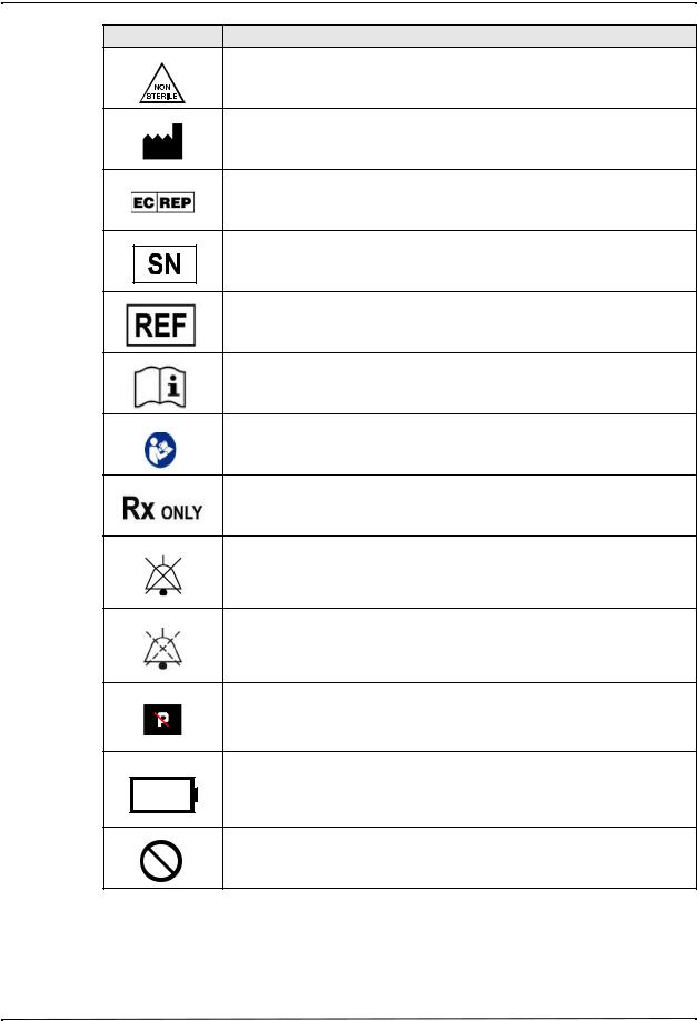
Symbols Used on the Equipment
Symbol Description
Not sterile.
Manufacturer.
Authorized representative in the European Community.
Serial Number.
Catalogue number.
Consult instructions for use.
Refer to instruction manual/booklet.
Prescription only.
Alarm audio is currently off.
Alarm audio is currently paused.
Pacer indicator disabled.
Battery charging status.
Do not use device, cables, or probes in an MRI environment.
9650-000820-01 Rev. K |
Propaq M Operator’s Guide |
1-5 |

Chapter 1 General Information
Conventions
This guide uses the following conventions:
Within text, the names and labels for physical buttons and softkeys appear in boldface type (for example, “Press the IBP quick access key”).
This guide uses uppercase italics for audible prompts and for text messages displayed on the screen (for example, INITIALIZING).
Warning! |
Warning statements alert you to conditions or actions that can result in personal injury |
|
or death. |
|
|
Caution Caution statements alert you to conditions or actions that can result in damage to the unit.
Propaq M Indications for Use
The Propaq M is intended for use by trained medical personnel who are familiar with basic monitoring, vital sign assessment, and the use of the Propaq M. The Propaq M is also intended for use by (or on the order of) physicians at the scene of an emergency or in a hospital emergency room, intensive care unit, cardiac care unit, or other similar areas of a hospital. The usage may be in an ambulance or at the scene of an emergency. It is also intended to be used during the transport of patients. The Propaq M will be used whenever it is required to monitor any of those functions that are included (as options) in the device. The Propaq M unit can be used on pediatric patients (as described in the following table) and on adult patients (21 years of age or older) with and without heart dysfunction.
Pediatric Patient Subpopulation |
Approximate Age Range |
|
|
Newborn (neonate) |
Birth to 1 month of age. |
|
|
Infant |
1 month to 2 years of age. |
|
|
Child |
2 to 12 years of age. |
|
|
Adolescent |
12 to 21 years of age. |
|
|
ECG Monitoring
The Propaq M is intended for use to monitor and/or record 3-, 5-, or 12-lead ECG waveform and heart rate, and to alarm when heart rate is above or below limits set by the operator. The patient population will range from newborn (neonate) to adult, with and without heart dysfunction.
Non-Invasive Blood Pressure Monitoring
The Propaq M unit’s NIBP option is intended for use to make non-invasive measurements of arterial pressure and heart rate, and to alarm if either parameter is outside of the limits set by the user. Measurements are made using an inflatable cuff on the patient's arm or leg. The patient population will range from newborn (neonate) to adult.
1-6 |
www.zoll.com |
9650-000820-01 Rev. K |

Propaq M Indications for Use
Temperature Monitoring
The Propaq M is intended for use to make continuous temperature measurements of rectal, esophageal, or surface temperatures, and to alarm if the temperature is outside of the limits set by the user. The patient population will range from newborn (neonate) to adult.
SpO2 Monitoring
The Propaq M pulse CO-oximeter, with Masimo Rainbow® SET® technology, is intended for use for continuous noninvasive monitoring of functional oxygen saturation of arterial hemoglobin (SpO2), pulse rate, carboxyhemoglobin saturation (SpCO), and/or methemoglobin
saturation (SpMet), total hemoglobin (SpHb), oxygen content (SpOC), pleth variability index (PVI), and/or perfusion index (PI). The pulse CO-oximeter and accessories are indicated for use on adult, pediatric, and neonatal patients during both no motion and motion conditions, and for patients who are well or poorly perfused, in hospitals, hospital-type facilities, or in mobile environments.
Respiration Monitoring
The Propaq M is intended for use to continuously monitor respiration rate and to alarm if the rate falls outside of the range set by the operator. Because the measurement method actually measures respiratory effort, apnea episodes with continued respiratory effort (such as obstructive apnea) may not be detected. It is not intended to be used as an apnea monitor. The patient population will range from newborn (neonate) to adult.
CO2 Monitoring
The Propaq M is intended for use to make continuous noninvasive measurement and monitoring of carbon dioxide concentration of the expired and inspired breath and breath rate. The patient population will range from newborn (neonate) to adult.
Invasive Pressure Monitoring
The Propaq M is intended for use to display and make continuous invasive pressure measurements from any compatible pressure transducer. The primary intended uses are arterial blood pressure, central venous pressure and intracranial pressure monitoring. Any contraindications of the particular transducer selected by the user shall apply. The patient population will range from newborn (neonate) to adult.
12-Lead Analysis
The 12-lead ECG Analysis is intended for use in acquiring, analyzing and reporting ECG data, and to provide interpretation of the data for consideration by caregivers. The interpretations of ECG data offered by the device are only significant when used in conjunction with caregiver overread as well as consideration of all other relevant patient data. The 12-lead ECG Analysis is intended for use on adults (> 18 years of age).
9650-000820-01 Rev. K |
Propaq M Operator’s Guide |
1-7 |

Chapter 1 General Information
Propaq M Product Functions
ECG Monitoring
The patient’s ECG is monitored by connecting the patient to the unit via a 3-, 5-, or 12-lead patient cable. The ECG waveform is presented on the display along with the following information:
•averaged heart rate, derived by measuring R to R intervals
•lead selection - I, II, III, aVR, aVL, aVF, V1, V2, V3, V4, V5, V6 (with ECG cable).
•ECG size - 0.125, 0.25, 0.50, 1.0, 2.0, 4.0 cm/mV, AUTO
•status messages
The ECG bandwidth is user selectable.
Batteries
Propaq M models use an easily replaced rechargeable lithium-ion battery pack (the SurePower II Battery Pack). A new, fully charged battery pack typically delivers more than 8 hours of ECG monitoring. Use of other functions (such as higher screen brightness or shorter NIBP intervals) reduces this time.
When a LOW BATTERY icon appears on the display and the unit emits three beeps in conjunction with the displayed battery icon, the battery must be replaced and recharged.
You can charge the battery by either of the following methods:
•Internal charging — plug the Propaq M into an auxiliary power adapter to automatically begin charging the installed battery pack. The front panel battery indicator operates as follows:
When the indicator is: |
It means: |
|
|
Steady yellow |
Battery is charging. |
|
|
Steady green |
Battery is charged. |
|
|
Alternating yellow and |
The charge state cannot be |
green |
determined or a battery charging |
|
fault has been detected. |
Not lit |
No battery in device. |
|
|
Note: Upon power up, it takes approximately 45 seconds for the LEDs on the battery to accurately display run time.
•External charging — use the ZOLL SurePower Battery Charger with the Propaq M/MD Charger Adaptor to charge the battery pack and test the battery’s capacity. For details, refer to the SurePower II Battery Pack Guide.
The Recalibration LED icon (  ) lights for approximately 10 seconds (after you press and release the Display button) if the battery needs to be calibrated. If the Recalibration LED lights, the runtime indicator will not display run time for that battery. For best performance of the battery, you should recalibrate the battery as soon as possible.
To manually recalibrate the SurePower II Battery Pack, you can insert the battery into the SurePower Charger Station and perform a Manual Test (for more information, see the ZOLL
SurePower Charger Station Operator’s Guide).
After you recalibrate the battery, the Recalibration LED will only flash when you press the
Display button.
1-8 |
www.zoll.com |
9650-000820-01 Rev. K |

Propaq M Product Functions
Ready For Use (RFU) Indicator
The Propaq M has an RFU indicator on the front panel that indicates if the device is ready for use. The RFU indicator has three states which are described in the following table.
State |
Description |
Action |
|
|
|
Ready for Use |
The device is ready for use. Patient |
None required. |
|
monitoring is functional and the |
|
|
battery is above the low battery |
|
|
capacity. |
|
|
Note: If the device is plugged into |
|
|
the auxiliary power adapter, the |
|
|
Ready for Use indicator may display |
|
|
even if the battery is depleted. |
|
|
Check the status of the battery |
|
|
before removing the device from the |
|
|
auxiliary power adapter. |
|
|
|
|
Flashing |
One or more of the following has |
Install a fully charged battery in the |
|
occurred: |
unit and check the RFU indicator |
|
• The battery is not properly |
again. If the RFU indicator |
|
continues to flash, remove the unit |
|
|
installed. |
from service and contact the |
|
• A low battery is installed. |
|
|
appropriate technical personnel or |
|
|
• A battery fault has occurred. |
the ZOLL Technical Service |
|
• There is no battery installed |
Department. |
|
while connected to auxiliary |
|
|
power. |
|
|
• One or more patient monitoring |
|
|
parameters have failed self-test |
|
|
(NIBP, SpO2, CO2, IBP, or |
|
|
Temp). |
|
|
• The front panel button self-test |
|
|
failed. |
|
|
• The speech database self-test |
|
|
failed. |
|
|
|
|
Do Not Use |
One or more of the following has |
Install a fully charged battery in the |
|
occurred: |
unit and check the RFU indicator |
|
• The battery is not properly |
again. If the RFU indicator |
|
continues to display the Do Not |
|
|
installed. |
Use symbol, remove the unit from |
|
• No battery is installed and |
|
|
service and contact the appropriate |
|
|
auxiliary power is not present. |
technical personnel or the ZOLL |
|
• A very low battery (below |
|
|
Technical Service Department. |
|
|
software shutdown limit) was |
|
|
installed. |
|
|
• ECG self-tests have failed, or |
|
|
other critical self-tests have |
|
|
failed. |
|
|
|
|
9650-000820-01 Rev. K |
Propaq M Operator’s Guide |
1-9 |

Chapter 1 General Information
Warnings
General
•These operating instructions describe the functions and proper operation of the Propaq M products. They are not a substitute for a formal patient care training course. Operators should obtain formal training from an appropriate authority before using this monitor for patient care.
•Proper operation of the unit and correct electrode placement is critical to obtaining optimal results. Operators must be thoroughly familiar with proper device operation.
•Allow ample slack in cables to make sure that cables do not tug at electrodes.
•Do not disassemble the unit. A shock hazard exists. Refer all problems to authorized service personnel.
•Follow all recommended maintenance instructions. If a problem occurs, obtain service immediately. Do not use the monitor until it has been inspected by appropriate personnel.
•The Propaq M unit might not perform to specifications when stored at the upper or lower extreme limits of storage temperature and then immediately put into use. The Propaq M unit should not be stored or used outside of the environmental limits provided in Appendix A of this manual.
•Avoid using the Propaq M adjacent to, or stacked on, other equipment. If unavoidable, verify that the unit operates normally in this configuration before clinical use.
•The Propaq M unit should be installed and put into service according to the EMC information in Appendix A of this manual.
•The use of transducers and cables other than those specified in this manual and related Propaq M option manual inserts may result in increased emissions or decreased immunity of the Propaq M.
•Do not use or place the unit in service if the Ready For Use indicator (at the upper right of the front panel) displays a red circle with a line through it.
•Carefully route patient cables to avoid tripping over them, or inadvertently pulling the unit onto the patient.
•Always inspect the unit for damage if it has been dropped.
•Only authorized personnel should use the Supervisor menus.
•If uncertain about the accuracy of any measurement, first check the patient’s vital signs by alternate means, and then make sure the monitor is functioning correctly.
•Before disposing equipment, in order to avoid contaminating or infecting personnel, the environment, or other equipment, it is important to disinfect and decontaminate the monitor and any appropriate device accessories appropriately and remove the batteries. Then dispose of the device and accessories in accordance with your country’s regulations for equipment containing electronic parts.
1-10 |
www.zoll.com |
9650-000820-01 Rev. K |
Warnings
ECG Monitoring
•Implanted pacemakers might cause the heart rate meter to count the pacemaker rate during incidents of cardiac arrest or other arrhythmias. Dedicated pacemaker detection circuitry may not detect all implanted pacemaker spikes. Check the patient's pulse; do not rely solely on heart rate meters. Patient history and physical examination are important factors in determining the presence of an implanted pacemaker. Pacemaker patients should be carefully observed. See “Pacemaker Pulse Rejection:” on page A-3 of this manual for disclosure of the pacemaker pulse rejection capability of this instrument.
•Use only ECG electrodes that meet the AAMI standard for electrode performance (AAMI EC-12). Use of electrodes not meeting this AAMI standard could cause the ECG trace recovery after defibrillation to be significantly delayed.
•Do not place electrodes directly over an implanted pacemaker.
•The Propaq M unit detects ECG electrical signals only. It does not detect a pulse (effective circulatory perfusion). Always verify pulse and heart rate by physical assessment of the patient. Never assume that the display of a nonzero heart rate means that the patient has a pulse.
•Excessive artifact can result due to improper skin preparation of the electrode sites. Follow skin preparation instructions in Chapter 6: “Monitoring ECG.”
•Equipment such as electrocautery or diathermy equipment, RFID readers, electronic article surveillance (EAS) systems, or metal detectors that emit strong radio frequency signals can cause electrical interference and distort the ECG signal displayed by the monitor, thereby preventing accurate rhythm analysis. Ensure adequate separation between such emitters, the device, and the patient when performing rhythm analysis.
•Shock Hazard: Use of accessories, other than those specified in the operating instructions, may adversely affect patient leakage currents.
•Certain line-isolation monitors may cause interference on the ECG display and may inhibit heart rate alarms.
Pulse Oximeter
•Keep the ZOLL finger probe clean and dry.
•SpO2 measurements may be affected by certain patient conditions: severe right heart failure, tricuspid regurgitation or obstructed venous return.
•SpO2 measurements may be affected when using intravascular dyes, in extreme vasoconstriction or hypovolemia or under conditions where there is no pulsating arterial vascular bed.
•SpO2 measurements may be affected in the presence of strong EMI fields, electrosurgical devices, IR lamps, bright lights, improperly applied sensors; the use of non-ZOLL sensors, or damaged sensors; in patients with smoke inhalation, or carbon monoxide poisoning, or with patient movement.
•Tissue damage can result if sensors are applied incorrectly, or left in the same location for an extended period of time. Move sensor every 4 hours to reduce possibility of tissue damage.
•Do not use any oximetry sensors during MRI scanning. MRI procedures can cause conducted current to flow through the sensors, causing patient burns.
•Do not apply SpO2 sensor to the same limb that has an NIBP cuff. The SpO2 alarm may sound when the arterial circulation is cut off during NIBP measurements, and may affect SpO2 measurements.
•In some instances, such as obstructed airway, the patient's breathing attempts may not produce any air exchange. These breathing attempts can still produce chest size changes, creating impedance changes, which can be detected by the respiration detector. It is best to use the pulse oximeter whenever monitoring respirations, to accurately depict the patient's respiratory condition.
9650-000820-01 Rev. K |
Propaq M Operator’s Guide |
1-11 |

Chapter 1 General Information
Noninvasive Blood Pressure
•Only a physician can interpret pressure measurements.
•Blood pressure measurement results may be affected by the position of the patient, his or her physiological condition and other factors.
•Substitution of a component different from that supplied by ZOLL (e.g., cuff, hoses, etc.) may result in measurement error. Use only ZOLL-approved cuffs and hoses. To avoid the risk of intravenous line misconnection and possible introduction of air into a patient’s blood, do not modify the NIBP system or hoses with Luer Lock adapters.
•Do not use a blood pressure cuff on the limb being used for IV infusion or for SpO2 monitoring.
•Accurate pressure readings may not be achieved on a person experiencing arrhythmias, shaking, convulsions or seizures. Medication may also affect pressure readings. The correct size cuff is essential for accurate blood pressure readings.
•Blood pressure hoses must be free of obstructions and crimps.
•If the patient’s cuff is not at heart level, an error in measurement may result.
•When monitoring blood pressure at frequent intervals, observe the cuffed extremity of the patient for signs of impeded blood flow.
•Do not monitor one patient’s NIBP while monitoring another patient’s ECG.
•Blood pressure measurement may be inaccurate if taken while accelerating or decelerating in a moving vehicle.
•If an NIBP measurement result is questionable or “motion” indication is displayed, repeat the measurement. If the repeated measurement result is still questionable, use another blood pressure measurement method.
•Do not use the NIBP on cardiopulmonary bypass patients.
IBP
•To ensure compatibility and electrical safety, accessory pressure sensors should comply with ANSI/AAMI BP-22 and IEC 60601-2-34 for IBP or ANSI/AAMI NS28 for ICP.
•Follow instructions supplied with any accessory pressure sensor regarding calibration and removal of trapped air.
•Avoid touching metal parts of any transducer while it is in contact with the patient.
•Do not reuse any components that are labeled for single use only.
•Transducers should be rated to withstand an accidental drop of at least a meter onto a hard surface.
•Transducers that are subject to immersion in liquids should be rated as watertight.
CO2
•During MRI scanning, the monitor must be placed outside the MRI suite. When the monitor is used outside the MRI suite, EtCO2 monitoring can be implemented using a long FilterLine® which permits placement of the monitor outside the MRI suite.
•When using the monitor with anesthetics, nitrous oxide or high concentrations of oxygen, connect the gas outlet to a scavenger system.
•Use only Oridion Microstream CO2 sampling lines.
•Microstream CO2 sampling lines are labeled for single patient use only. Do not reuse sampling lines.
•If using the CO2 Monitor for extended critical care, replace the airway adapter every 24 hours or when it becomes occluded.
•CO2 readings and respiratory rate can be affected by sensor application errors, certain ambient environmental conditions, and certain patient conditions.
1-12 |
www.zoll.com |
9650-000820-01 Rev. K |

Warnings
Respiration
•Do not operate the Propaq M with any other monitor with respiration measurements on the same patient. The two devices could affect the respiration accuracy.
•The device should not be used as an apnea monitor.
Ferromagnetic Equipment
Biomedical equipment and accessories, such as ECG electrodes, cables, and oximeter probes contain ferromagnetic materials. Ferromagnetic equipment must not be used in the presence of high magnetic fields created by magnetic resonance imaging (MRI) equipment.
The large magnetic fields generated by an MRI device can attract ferromagnetic equipment with an extremely violent force, which could cause serious personal injury or death to persons between the equipment and the MRI device.
Battery
•Although the device can operate with auxiliary power alone, ZOLL strongly recommends that you operate the unit with a battery installed at all times. Operating the unit with a battery provides a backup in case of AC power shortage, and results in faster charge time. The battery can be automatically recharged while it is installed in the unit. Keep a fully charged spare battery pack with the monitor at all times.
•Test battery packs regularly. A battery that does not pass the ZOLL charger’s capacity test might cause the Propaq M unit to shut down unexpectedly.
•If the Low Battery indication occurs at any time during operation, immediately replace the battery pack.
•If the LOW BATTERY icon appears, plug the Propaq M unit into a power source or install a fully charged battery pack. When the warning low battery shutdown prompt appears, immediately replace the battery pack with a fully charged pack or plug the Propaq M unit into a power source, as unit shut down due to a low battery condition is imminent.
•If mistreated, a battery pack might explode. Do not disassemble a battery pack or dispose of it in fire.
Operator Safety
•Do not use the Propaq M in the presence of oxygen-rich atmospheres, flammable anesthetics, or other flammable agents (such as gasoline). Using the unit in such environments might cause an explosion.
•Do not use the unit near or within standing water. Electrical safety might be compromised when the monitor is wet.
•The use of accessory equipment that does not comply with the equivalent safety requirements of the Propaq M monitor could reduce the level of safety of the combined system. When choosing accessory equipment, consider the following:
•Use of the accessory in the patient vicinity.
•Evidence that the safety certification of the accessory has been performed in accordance with the appropriate IEC (EN) 60601-1 and/or IEC (EN) 60601-1-1 harmonized national standards.
•Always check that the equipment functions properly and is in proper condition before use.
•To avoid the risk of electrical shock, do not allow printer to come into contact with other conductive parts, such as equipment connected to the USB port.
9650-000820-01 Rev. K |
Propaq M Operator’s Guide |
1-13 |

Chapter 1 General Information
Patient Safety
•This equipment should be connected to only one patient at a time.
•To ensure patient safety, do not place the monitor in any position that might cause it to fall on the patient.
•To ensure patient safety, connect the Propaq M only to equipment with circuits that are electrically isolated.
•Use only high-quality ECG electrodes.
•Do not use ECG electrodes if the gel is dried, separated, torn or split from the foil; patient burns may result from using such electrodes.
•Check the expiration date on the electrode packaging. Do not use electrodes after their expiration date.
•Excessive body hair or wet, diaphoretic skin can inhibit electrode coupling to the skin. Clip excess hair and dry any moisture from the area where an electrode is to be attached.
•Carefully route the patient cables away from the patient’s neck to reduce the possibility of patient entanglement or strangulation.
•To avoid electrosurgery burns at monitoring sites, ensure proper connection of the electrosurgery return circuit so that a return path cannot be made through monitoring electrodes or probes.
•During electrosurgery, observe the following guidelines to minimize electrosurgery unit (ESU) interference and provide maximum operator and patient safety:
•Keep all patient monitoring cables away from earth ground, ESU knives, and ESU return wires.
•Use electrosurgical grounding pads with the largest practical contact area.
•Always ensure proper application of the electrosurgical return electrode to the patient.
•Check electrical leakage levels before use. Leakage current might be excessive if more than one monitor or other piece of equipment is connected to the patient.
Cautions
•If the unit is to be stored longer than 30 days, remove the battery pack.
•Do not sterilize the monitor, or its accessories unless the accessories are labelled as sterilizable.
•Do not immerse any part of the monitor in water.
•Do not use the monitor if excessive condensation is visible on the device. Wipe only the outside with a damp cloth.
•Do not use ketones (such as acetone or MEK) on the monitor.
•Avoid using abrasives (including paper towels) on the display window.
•To achieve the specified level of protection against spilled or splashed liquids, thoroughly dry all exposed surfaces of this device prior to operation or connections to auxiliary power.
•If liquids enter the device connectors, remove all liquid from the connectors and allow the device to dry thoroughly prior to use.
•Grounding reliability can be achieved only when the equipment is connected to a receptacle marked “HOSPITAL ONLY,” “HOSPITAL GRADE,” or equivalent. If the grounding integrity of the line cord or ac receptacle is questionable, operate the monitor using battery power only.
•Do not connect to an electrical outlet controlled by a wall switch or dimmer.
•For accurate ECG information, and to protect against noise and other interference, use only internal current-limiting ECG cables specified or supplied by ZOLL.
•For continued safety and EMI performance, use only the line cord supplied by ZOLL.
1-14 |
www.zoll.com |
9650-000820-01 Rev. K |

Restarting the Monitor
•Electrical installation of the room or the building in which the monitor is to be used must comply with regulations specified by the country in which the equipment is to be used.
•Dispose of battery packs in accordance with national, regional and local regulations. Battery packs should be shipped to a reclamation facility for recovery of metal and plastic compounds as the proper method of waste management.
Restarting the Monitor
Certain events require the Propaq M products to be restarted after they shut off or become inoperative (for example, when the battery runs down and the unit shuts off).
In such a case, always try to restore monitor operation as follows:
1.Press the power switch on the top of the unit to turn it off.
2.If necessary, replace a depleted battery with a fully charged pack, or connect the monitor to auxiliary power.
3.Press the power switch on the top of the unit to turn it back on.
This sequence is necessary to restart the monitor and can also be used to clear some fault messages when immediate use of the monitor is required.
If the Propaq M unit is powered off for less than 2 minutes, all patient monitoring parameter settings will be retained. If the unit has been powered off for at least two minutes, it will be considered a New Patient and all of the patient-specific parameters (alarm limits, etc.) will be reset to their default values.
Notification of Adverse Events
As a health care provider, you may have responsibilities under the Safe Medical Devices Act (SMDA), for reporting to ZOLL Medical Corporation, and possibly to the FDA, the occurrence of certain events.
These events, described in 21 CFR Part 803, include device-related death and serious injury or illness. In addition, as part of our Quality Assurance Program, ZOLL Medical Corporation requests to be notified of device failures or malfunctions. This information is required to ensure that ZOLL Medical Corporation provides only the highest quality products.
9650-000820-01 Rev. K |
Propaq M Operator’s Guide |
1-15 |

Chapter 1 General Information
Software License
Note: Read this Operator’s Guide and License agreement carefully before operating any of the Propaq M products.
Software incorporated into the system is protected by copyright laws and international copyright treaties as well as other intellectual property laws and treaties. This software is licensed, not sold. By taking delivery of and using this system, the Purchaser signifies agreement to and acceptance of the following terms and conditions:
1.Grant of License: In consideration of payment of the software license fee which is part of the price paid for this product ZOLL Medical Corporation grants the Purchaser a nonexclusive license, without right to sublicense, to use the system software in object-code form only.
2.Ownership of Software/Firmware: Title to, ownership of and all rights and interests in the system software and all copies thereof remain at all times vested in the manufacturer, and Licensors to ZOLL Medical Corporation and they do not pass to purchaser.
3.Assignment: Purchaser agrees not to assign, sublicense or otherwise transfer or share its rights under the license without the express written permission of ZOLL Medical Corporation.
4.Use Restrictions: As the Purchaser, you may physically transfer the products from one location to another provided that the software/firmware is not copied. You may not disclose, publish, translate, release or distribute copies of the software/firmware to others. You may not modify, adapt, translate, reverse engineer, decompile, crosscompile, disassemble or create derivative works based on the software/firmware.
NO IMPLIED LICENSE
Possession or purchase of this device does not convey any express or implied license to use the device with replacement parts which would, alone, or in combination with this device, fall within the scope of one or more of the patents relating to this device.
Service
The Propaq M only requires recalibration of the CO2 module. Service is required after 20,000 hours of use of the CO2 module. Appropriately trained and qualified personnel should, however, perform periodic tests of the monitor functionality to verify proper operation.
If a unit requires service, contact the ZOLL Technical Service Department.
For customers In the U.S.A. |
For customers outside the U.S.A. |
|
Telephone: |
1-800-348-9011 |
Call the nearest authorized ZOLL Medical Corporation |
|
1-978-421-9655 |
representative. |
Fax: |
1-978-421-0010 |
To locate an authorized service center, contact the |
|
|
International Sales Department at |
|
|
ZOLL Medical Corporation |
|
|
269 Mill Road |
|
|
Chelmsford, MA 01824-4105 |
|
|
Telephone: 1-978-421-9655 |
|
|
|
1-16 |
www.zoll.com |
9650-000820-01 Rev. K |

Service
When requesting service, please provide the following information to the service representative:
•Unit serial number
•Description of the problem
•Department using the equipment and name of the person to contact
•Purchase order to allow tracking of loan equipment
•Purchase order for a unit with an expired warranty
•Sample ECG or other stripcharts demonstrating the problem (if available and applicable), less any confidential patient information.
Returning a unit for service
Before sending a unit to the ZOLL Technical Service Department for repair, obtain a service request (SR) number from the service representative.
Remove the battery pack from the unit. Pack the unit with its cables and battery in the original containers (if available) or equivalent packaging. Be sure the assigned service request number appears on each package.
For customers |
Return the unit to |
|
|
In the U.S.A. |
ZOLL Medical Corporation |
|
269 Mill Road |
|
Chelmsford, MA 01824-4105 |
|
Attention: Technical Service Department (SR number) |
|
Telephone: 1-800-348-9011 |
|
|
In Canada |
ZOLL Medical Canada Inc. |
|
1750 Sismet Road, Unit #1 |
|
Mississauga, ON L4W 1R6 |
|
Attention: Technical Service Department (SR number) |
|
Telephone: 1-866-442-1011 |
|
|
In other locations |
The nearest authorized ZOLL Medical Corporation representative. |
|
To locate an authorized service center, contact the International Sales |
|
Department at |
|
ZOLL Medical Corporation |
|
269 Mill Road |
|
Chelmsford, MA 01824-4105 |
|
Telephone: 1-978-421-9655 |
|
|
9650-000820-01 Rev. K |
Propaq M Operator’s Guide |
1-17 |

Chapter 1 General Information
The ZOLL Serial Number
Each ZOLL product displays a serial number that contains information about that product. From left to right, ZOLL serial numbers are structured as follows:
•A two-character product code
•A three-character date-of-manufacture code
•A product serial number of six or more alphanumeric characters
The first two characters of the date-of-manufacture code give the last two digits of the year (for example, “06” appears for products manufactured in 2006). The last character of the date-of- manufacture code gives the month in which the product was manufactured. The month appears in the form of a single alphanumeric character: “A” for January, “B” for February, “C” for March, and so on through “L” for December.
The product serial number is a unique set of alphanumeric characters that ZOLL assigns to each individual unit.
1-18 |
www.zoll.com |
9650-000820-01 Rev. K |

Chapter 2
Product Overview
This chapter provides an overview of the Propaq M unit’s features, controls, and indicators. It provides illustrations of the Propaq M unit both with and without the optional printer.
9650-000820-01 Rev. K |
Propaq M Operator’s Guide |
2-1 |

Chapter 2 Product Overview
Propaq M Controls and Indicators
1
2
3

 4
4
5
4 

6
7
 8
8
|
Item |
Description |
|
|
|
1 |
Handle |
Integrated carrying handle. |
|
|
|
2 |
Front panel |
Includes the display screen and primary controls. |
|
|
|
3 |
Speaker |
Emits R-wave detection beeps and alarm tones. |
|
|
|
4 |
Patient connectors |
For details, refer to “Patient Cables and Connectors” on |
|
|
page 2-8. |
5 |
USB device connector |
For connecting the Propaq monitor to a USB device. For |
|
|
details, refer to “Transferring Data to a USB Device” on |
|
|
page 14-3“. |
|
|
|
6 |
Battery compartment |
Holds a rechargeable lithium ion battery pack. |
|
|
|
7 |
Auxiliary power connector |
For connecting the device to an auxiliary power adapter. |
|
|
|
8 |
Dock connector |
For connecting the device to a docking station. |
|
|
|
2-2 |
www.zoll.com |
9650-000820-01 Rev. K |
Loading...