

Page 1
LIMITED 1 YEAR WARRANTY
®
Zircon Corporation, ("Zircon") warrants this product to be free from
defects in materials and workmanship for one year from the date of
purchase. Any in-warranty defective product returned to Zircon*,
freight prepaid with proof of purchase date and $5.00 to cover
postage and handling, will be repaired or replaced at Zircon’s option.
This warranty is limited to the electronic circuitry and original case of
the product and specifically excludes damage caused by abuse,
unreasonable use or neglect. This warranty is in lieu of all other
warranties, express or implied, and no other representations or claims
of any nature shall bind or obligate Zircon. Any implied warranties
applicable to this product are limited to the one year period
following its purchase. IN NO EVENT WILL ZIRCON BE LIABLE FOR
ANY SPECIAL, INCIDENTAL OR CONSEQUENTIAL DAMAGES
RESULTING FROM POSSESSION, USE OR MALFUNCTION OF THIS
PRODUCT.
In accordance with government regulations, you are advised that:
(i) some states do not allow limitations on how long an implied
warranty lasts and/or the exclusion or limitation of incidental or
consequential damages, so the above limitations and/or exclusions
may not apply to you, and further (ii) this warranty gives you specific
legal rights and you may also have other rights which vary from state
to state.
Return product freight prepaid with proof of purchase date (dated
sales receipt) and $5.00 to cover postage and handling, to:
Zircon Corporation
*Attn: Returns Department
2390 Boswell Road, Suite 300
Chula Vista, CA 91914-3510 USA
Be sure to include your name and return address. Out of warranty
service and repair, where proof of purchase is not provided, shall be
returned with repairs charged C.O.D. Allow 4 to 6 weeks for delivery.
Customer Service, 800/245-9265 or 408/866-8600
Monday – Friday, 8 a.m. to 5 p.m., PST
E-mail: customerservice@zircon.com
www.zircon.com
©2001 Zircon Corporation • P/N00000 • REV A 03/01
Zircon Corporation
1580 Dell
800-245-9265 408-866-8600
Campbell, CA 95008
www.zircon.com
Remote Controlled Rotator
RCR
Instructions
Contents
Components . . . . . . . . . . .2
Setting Up . . . . . . . . . . . .3
Operation . . . . . . . . . . . . .5
Laser Receiver . . . . . . . . .7
Changing Batteries . . . . . .9
Calibration . . . . . . . . . . . .10
Technical Data . . . . . . . . .11
Warranty . . . . . . . . . . . . .12
Page 2
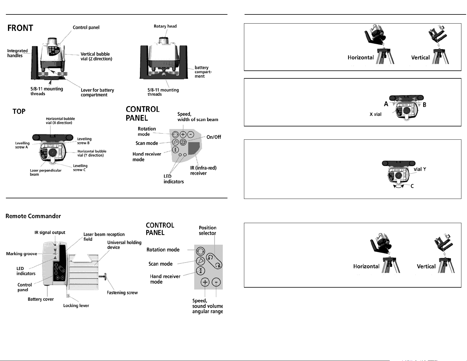
RCR Components
Remote Commander Components
Setting Up
Set the RCR up on a firm base or mount it
onto a tripod with a 5/8-11 thread.
Adjusting horizontal settings
Start adjusting the level bubble vial X by
turning the levelling screws (A) and (B).
X-vial
Always look vertically at the vial in order to
avoid reading errors. Now turn the levelling
screw (C) to adjust the bubble vial Y.
Y-vial
Repeat the whole action as necessary.
Adjusting vertical settings
Set the RCR up vertically on its integrated
handles or mount the RCR onto a tripod.
Now adjust only the vertical bubble level
vial (Z) with the levelling screw (C).
Page 3

Operation
Operation
Switch on RCR:
Press and hold the "On/Off" button for
1 second until the head of RCR starts
rotating. The rotation mode is
activated.
Spot mode:
The rotating laser sends out a spot
laser beam that can be focused on one
point. In order to get into the spot
mode, reduce the speed by pressing
the minus button to zero.
To rotate laser
Change its position by manually
turning the rotary head
Scan mode
Scan Mode is a light-intensive segment
of line at user-selected width, with an
adjustable position.
To activate Scan Mode, press the
ACTIVATE button on the control panel or
on the Remote Commander control
panel.
To change scan angle, press the + and buttons on either control panel.
To change position of the scan area,
manually turn the rotary head, or use
the Change Position buttons on the
Remote Commander.
Rotation mode
A laser beam rotating 360° with a speed
of up to 120 rpm, or 550 rpm if using
receiver.
Using either control panel, activate
Rotation Mode by pressing the spin
button.
Rotate laser with Remote
Commander
Change position by pressing the
Position Selector buttons.
Change rotation speed by pressing the +
or - buttons.
Page 4

Operation
Using the Remote Commander as a Laser Receiver
Hand receiver mode
Hand receiver mode gives you
optimum reception quality with a
constantly high speed of rotation
(maximum speed = 550 rpm).
Activate this mode by pressing the Hand
Receiver button on the RCR control
panel.
Pressing the same button on the Remote
Commander control panel activates the
Remote Commander as a laser receiver.
Note referring to all modes
The red LED lights up when you've
reached the limit of range (e.g.
maximum speed, biggest scan angle).
Sound volume control
Use the + and - buttons to adjust volume
after pressing the receiver activation
button. The LEDs light up to indicate
low, medium, and maximum sound,
or sound off.
Working with the laser receiver
The receiver can detect the laser beam at distances of up to 400 feet.
Hold the laser receiver with the IR receiver at the height
of the rotating laser beam and facing the laser beam.
By means of LEDs and sound signals you can find the
exact height of the laser level beam.
If the top LED lights, a descending series of tones sounds.
Move the Remote Commander downwards.
If the bottom LED lights, and an ascending series
of tones sounds, move the Remote Commander
upwards.
Using the Remote Commander as a Laser Receiver
Activating the laser receiver
mode
Switch on the laser receiver mode.
In order to ensure that the mode is also
activated on the RCR, point the IR
transmitting diode of the
RemoteCommander at the RCR unit.
Activation is indicated by lighting of
red/green LEDs and a signal sound on
the Remote Commander.
When the middle LED is yellow, you are very close,
and the two-note tone tells you to move the
Remote Commander slowly upwards or downwards,
until the middle LED turns green.
When the middle LED is green, a series of equal tones sounds.
The Remote Commander is exactly at laser level.
Note:
When the middle LED gives off yellow light, you are already
within a 3/16" range round the laser level (free-hand
measuring). You will achieve a more accurate result (fine measuring), when
the RemoteCommander is fixed (e.g. attached to a levelling staff). Then the
green LED shows the exact center.
Page 5

Using the Remote Commander as a Laser Receiver
Calibration
Special features of Remote
Commander
By using the universal holding device the
RemoteCommander can be attached to a
levelling staff. LEDs on the back show the
same readings as the front so you can work
from behind the receiver.
Through the integrated magnet the Remote Commander can also be
used as an electronic target plate, e.g. in acoustic ceiling construction
and when setting up and adapting metal and storage shelves.
Changing Batteries
RCR:
When the red LED is constantly flashing,
the batteries must be changed. To do
this, pull the lever under the unit slightly
downward and forward. Remove the
door and insert new batteries with
polarities shown on case indicating
which end of battery faces out. Replace
door. Requires four AA batteries.
RemoteCommander:
The RCR is a high-precision rotating laser and has
been factory calibrated within the tolerance
specified. Regularly check the calibration before
use, after transporting and after long storage
periods.
Be aware that a re-calibration performed by the
user is only as an approximation and the accuracy
of calibration depends on your care.
X/Y-axis Preparation
Note: For the purpose of calibration or
verifying level, the unit should be placed at a
distance of approx. 40-60 ft. from a vertical
target (e.g. wall).
1.Turn the levelling screws all the way down until
they stop.
2.Make a reference mark on each with a pencil.
Using the mark as an aid, turn the levelling screws
each up again by 3 turns.
3.Set the unit on a flat, somewhat level surface or
screw it onto a tripod.
4.Align the surface or the tripod in such a way that
the bubbles of the RCR are coarsely adjusted and
move freely.
Turn the knob on the bottom side and
remove it. Change batteries inserting
with plus sign facing in and replace
knob. Requires two AA batteries.
Connection of an external AC adaptor to the rotation laser
When connecting an external AC adaptor, the batteries will be bypassed. It is not
possible to charge rechargeable batteries with the power supply attached to the
rotation unit. Please use only the AC adaptor supplied.
Note:
Batteries should not be exposed to excessive heat, such as sunshine or fire. å
Checking the calibration of the Y axis
1. Mark either levelling screw A or B as a reference
screw. Align the unit only with the other levelling
screws.
2. Level the unit with the other two levelling
screws. Turn on and shine beam on a vertical
target surface 50 to 65 feet away.
Note:
Any mode can be used but spot mode will be
brighter and more visible at longer distances.
3. When levelled, mark the point A on the target.
Page 6

Calibration
Calibration
4. Turn the unit 180° without changing the
tripod
or surface height.
5. Using the same two levelling screws,
relevel unit.
6. Mark point B on the target.
If point B is at the same height as
point A, then the Y level is accurately
calibrated. If this is not the case, the
unit must be recalibrated.
Re-calibration of the Y axis:
1. Adjust the levelling screws (do not
use the reference screw) until the laser
is exactly centered between points A
and B. Take time to be as precise as
possible.
2. Remove the caps on the ends of the
bubble vial and reset the vial with the
calibrating screws using the hex
wrench supplied.
3. Gently raise or lower either end of
the vial as needed to center the
bubble. Replace caps.
Checking and re-calibration - X
axis
Proceed in the same way as for
checking and calibration of the Y axis
but turn the unit 90°, to align the laser
beam over the X vial.
Z axis: Calibrate vertical vial
Note: Prior to any Z axis calibration, make sure that the
horizontal vials (X and Y vials) have been correctly calibrated.
1. Set the unit up horizontally between two targets. (Remove
the protective cap at the side of the
bubble vial before calibrating)
2. Mark points A1 and B1 on the
targets.
3. Set the unit up vertically in the
vicinity of target A.
4. The laser strikes the first target and marks point A2 at the
same time.
5. Measure the distance between A1 and A2 (a).
6. Transfer the distance measured (a) to target B.
7. Adjust the laser beam with the levelling screw to the height
of B2.
8. If the bubble does not indicate
levelled, gently raise or lower either
end of the vial as needed to center
the bubble. Replace caps.
Technical Data
Laser Class II
Output power <= 1 mW horizontal; <0.33 mW vertical
Wavelength 635 nm
Accuracy ± 1/8” at 50 ft. (± 3.1mm at 15 m)
Vials ground glass, 1.75 arc minutes
Beam splitter ±20 arc seconds
Functions
Operating modes rotating, scan, spot and receiver
Settings change of position, speed, sound, volume, angular range, position
Speed of rotation 0 ... 120 rpm variable; 550 rpm for receiver
Remote control Infra-red, up to 50 ft. range
Power supply
Battery service life 40 hrs (4AA, alkaline
Continuous operation Jack for AC power adaptor
Other technical data
Working temperature 32°F to 122°F (0°C to 50°C)
Storage temperature 14°F to 158°F (-10°C to 70°C)
 Loading...