


LaserVision 7
LASERVISION
®
6.0 and LASERVISION
®
7.0
MODE D’EMPLOI
A
V
O
I
D
E
X
P
O
S
U
R
E
L
a
s
e
r
r
a
d
i
a
t
i
o
n
i
s
e
m
i
t
t
e
d
f
r
o
m
t
h
i
s
a
p
e
r
t
u
r
e
Z
i
r
c
o
n
C
o
r
p
o
r
a
t
i
o
n
1
5
8
0
D
e
l
l
A
v
e
.
C
a
m
p
b
e
l
l
,
C
A
9
5
0
0
8
T
h
i
s
p
r
o
d
u
c
t
c
o
n
f
o
r
m
s
t
o
A
p
p
l
i
c
a
b
l
e
S
t
a
n
d
a
r
d
s
o
f
2
1
C
F
R
p
a
r
t
s
1
0
4
0
.
1
0
a
n
d
1
0
4
0
.
1
1
Manufactured
at EM:
C
A
U
T
I
O
N
L
A
S
E
R
R
A
D
I
A
T
I
O
N
D
O
N
O
T
S
T
A
R
E
I
N
T
O
B
E
A
M
P
E
A
K
P
O
W
E
R
1
m
W
/
W
A
V
E
L
E
N
G
T
H
6
5
0
n
m
C
L
A
S
S
I
I
L
A
S
E
R
P
R
O
D
U
C
T
INSTRUCTION MANUAL
M
ANUAL DE INSTRUCCIONES
®
OPERATING INSTRUCTIONS
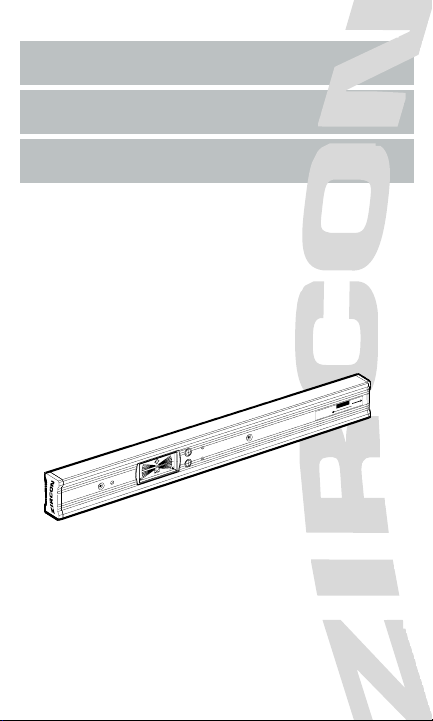
LaserVision
®
6.0 and LaserVision
®
7.0
The Zircon LaserVision is a high-precision electronic level combined
with a laser module. The LaserVision simplifies the time-consuming
task of laying out a job by allowing the user to mark level reference
points up to 150 ft. (45 m, LaserVision 6.0) or 300 ft. (90 m, LaserVision 7.0)
away. The LaserVision features an electronic LCD display which indicates the
relative deviation from level or plumb and the rotational direction needed to
achieve level or plumb. It also features an audio signal which sounds when level
and plumb are found. The LaserVision 7.0 has three preset angles commonly
used in construction jobs. Both models have the ability to store and recall any
angle over a 360 degree range. The LaserVision requires three AAA batteries
for the level module and three AAA batteries for the laser module.
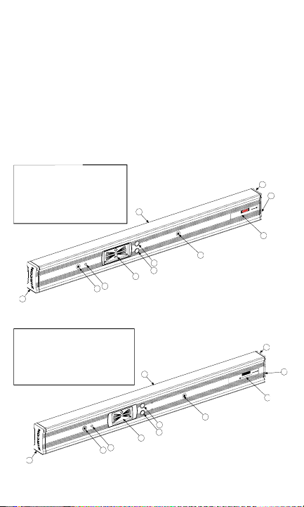
Figure 1a: LaserVision 7.0 Components
Figure 1b: LaserVision 6.0 Components
2
1
2
3
3
4
5
6
7
8
6. On/Off Button
7. Slope Button
8. Extrusion
9. Warning Label
10. Laser Power
Button
1. End Cap
2. End Cap
(Laser End)
3. Level Module
Attach Screw
4. Sound Port
5. Display Module
O
n
/
C
a
l
S
l
o
p
e
C
A
U
T
I
O
N
9
A
v
o
i
d
E
x
p
o
s
u
r
e
L
a
s
e
r
r
a
d
i
a
t
i
o
n
i
s
e
m
i
t
t
e
d
f
r
o
m
t
h
i
s
a
p
e
r
t
u
r
e
Z
i
r
c
o
n
C
o
r
p
o
r
a
t
i
o
n
1
5
8
0
D
e
l
l
A
v
e
.
C
a
m
p
b
e
l
l
,
C
A
9
5
0
0
8
T
h
i
s
p
r
o
d
u
c
t
c
o
n
f
o
r
m
s
t
o
A
p
p
l
i
c
a
b
l
e
S
t
a
n
d
a
r
d
s
o
f
2
1
C
F
R
p
a
r
t
s
1
0
4
0
.
1
0
a
n
d
1
0
4
0
.
1
1
MFG Date:
D
A
N
G
E
R
L
A
S
E
R
R
A
D
I
A
T
I
O
N
-
A
v
o
i
d
D
i
r
e
c
t
E
y
e
E
x
p
o
s
u
r
e
M
a
x
i
m
u
m
O
u
t
p
u
t
P
o
w
e
r
<
5
m
w
@
6
7
0
n
m
C
l
a
s
s
I
I
I
a
L
a
s
e
r
P
r
o
d
u
c
t
10
1
2
3
3
4
5
6
7
8
6. On/Off Button
7. Memory Button
8. Extrusion
9. Warning Label
10. Laser Power
Button
1. End Cap
2. End Cap
(Laser End)
3. Level Module
Attach Screw
4. Sound Port
5. Display Module
O
n
/
C
a
l
S
l
o
p
e
C
A
U
T
I
O
N
A
V
O
I
D
E
X
P
O
S
U
R
E
L
a
s
e
r
r
a
d
i
a
t
i
o
n
i
s
e
m
i
t
t
e
d
f
r
o
m
t
h
i
s
a
p
e
r
t
u
r
e
Z
i
r
c
o
n
C
o
r
p
o
r
a
t
i
o
n
1
5
8
0
D
e
l
l
A
v
e
.
C
a
m
p
b
e
l
l
,
C
A
9
5
0
0
8
T
h
i
s
p
r
o
d
u
c
t
c
o
n
f
o
r
m
s
t
o
A
p
p
l
i
c
a
b
l
e
S
t
a
n
d
a
r
d
s
o
f
2
1
C
F
R
p
a
r
t
s
1
0
4
0
.
1
0
a
n
d
1
0
4
0
.
1
1
Manufactured
at EM:
C
A
U
T
I
O
N
L
A
S
E
R
R
A
D
I
A
T
I
O
N
D
O
N
O
T
S
T
A
R
E
I
N
T
O
B
E
A
M
P
E
A
K
P
O
W
E
R
1
m
W
/
W
A
V
E
L
E
N
G
T
H
6
5
0
n
m
C
L
A
S
S
I
I
L
A
S
E
R
P
R
O
D
U
C
T
9
10
3
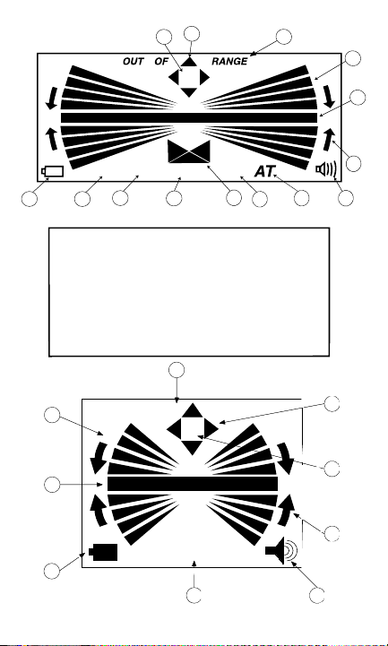
1. Low Battery Indicator
2. 1/8" per foot slope
Indicator
3. 1/4" per foot slope
Indicator
4.
Units Inch/Foot Indicator
5. Slope Direction Indicator
6. 1" per foot slope
Indicator
7. Angle Transfer Mode
Indicator
8. Sound Indicator
9. Directional Rotation
Arrows
10. Level / Plumb Bar
11. Main Display Wedges
12. Out of Range Indicator
13. Not Calibrated
Indicators
14. Calibration Sequence
Indicators
1
2
5
8
10
11
12
13
3
6
9
7
12
14
1/8" 1/4" 1"
4
IN/FT
Figure 2a: LaserVision 7.0 LCD Components
OUT OF RANGE
AT
12
1
2
3
5
6
7
8
9
4
Figure 2b: LaserVision 6.0 LCD Components
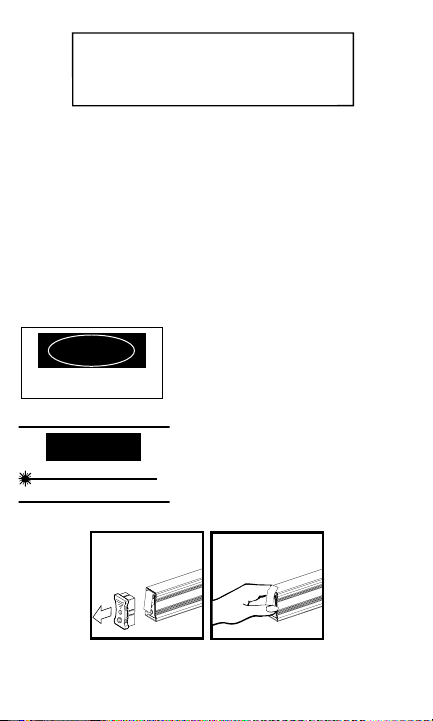
Preparing the LaserVision for Use
For safety reasons, the LaserVision 6.0 and 7.0 laser has been temporarily dis-
armed. To make the laser operational again:
• Remove the Laser-End Endcap (Figure 3 below).
• Pull up on the battery compartment door to release.
• Carefully remove the protective sticker from the laser module battery making
sure not to leave any pieces behind that might prevent the batteries from mak-
ing contact (Figure 4 below).
• Close and latch the battery compartment door.
• Put the Laser-End Endcap back in place.
The LaserVision is now ready for use.
LaserVision 7.0:
Warning: Be sure not to shine the
laser beam directly into anyone's eyes.
This can cause serious eye injury
or even blindness.
LaserVision 6.0:
Warning: Be sure not to shine the
laser beam directly into anyone's eyes.
This can cause serious eye injury
or even blindness.
Figure 3: Removing Figure 4: Removing
the Laser End Cap Protective Sticker
4
1
R
E
M
O
V
E
F
O
R
U
S
E
R
E
M
O
V
E
F
O
R
U
S
E
DANGER
LASER RADIATION - Avoid Direct Eye Exposure
Maximum Output Power < 5 mW @ 670 nm
Class IIIa Laser Product
E
X
La
e
m
CAUTION
LASER RADIATION
DO NOT STARE INTO BEAM
PEAK POWER 1 mW / WAVELENGTH 650 nm
CLASS II LASER PRODUCT
1. Main Display Wedges
2. Level and Plumb Bar
3. Low Battery Indicator
4. Angle Transfer Mode
Indicator
5. Sound Indicator
6. Directional Rotation
Arrows
7. Calibration Sequence
Indicators
8. Not Calibrated Indicators
9. Out of Range Indicator
TTuurrnniinngg tthhee LLaasseerrVViissiioonn OOnn aanndd OOffff
FFoorr tthhee LLeevveell
• Press the yellow ON/OFF button located next to the LCD (Figure 1, page 2).
To conserve batteries, the level portion of the LaserVision turns itself off after
one minute of inactivity. Once leveled, you can continue using the laser beam
even though the level itself has turned off.
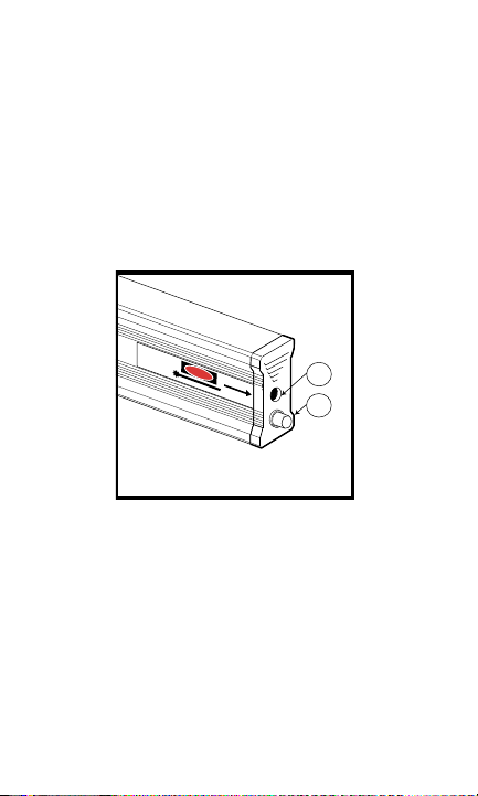
FFoorr tthhee LLaasseerr
• Press the push button on the laser end cap (Figure 5 below). When the laser is
activated, the push button glows red.
Warning: The LaserVision 7.0 has been outfitted with a Class IIIa laser (the
Laservision 6.0, with a Class II laser). Avoid direct eye exposure at all times.
For instance, do not look into the hole in the laser end cap to see if it is on.
Figure 5: Laser End Components
CChheecckkiinngg yyoouurr LLaasseerrVViissiioonn ffoorr pprrooppeerr ccaalliibbrraattiioonn
Prior to using any level, you should check its calibration. This is easy to
do if a flat, relatively level surface is available.
• In the case of the Zircon LaserVision, place the level on the surface and try to
align it with an edge or line on the surface.
• Turn the unit on.
• Note which end of the surface is indicated on the display to be higher and by
how many bars. For example, you may see the center bar with two bars on top
on the left side of the display and two bars on the bottom on the right side of
the display (Figure 6, page 6).
• Now turn the level around end for end with the same surface of the level
touching the relatively level surface and aligning the level to the same edge or
line on the surface (Figure 7, page 6). The display should now show the same
5
1. Laser Exit Point
2. Laser Power Button
1
2
A
v
o
i
d
E
x
p
o
s
u
r
e
L
a
s
e
r
r
a
d
i
a
t
i
o
n
i
s
e
m
i
t
t
e
d
f
r
o
m
t
h
i
s
a
p
e
r
t
u
r
e
Z
i
r
c
o
n
C
o
r
p
o
r
a
t
i
o
n
1
5
8
0
D
e
l
l
A
v
e
.
C
a
m
p
b
e
l
l
,
C
A
9
5
0
0
8
T
h
i
s
p
r
o
d
u
c
t
c
o
n
f
o
r
m
s
t
o
A
p
p
l
i
c
a
b
l
e
S
t
a
n
d
a
r
d
s
o
f
2
1
C
F
R
p
a
r
t
s
1
0
4
0
.
1
0
a
n
d
1
0
4
0
.
1
1
M
F
G
D
a
t
e
:
D
A
N
G
E
R
L
A
S
E
R
R
A
D
I
A
T
I
O
N
-
A
v
o
i
d
D
i
r
e
c
t
E
y
e
E
x
p
o
s
u
r
e
M
a
x
i
m
u
m
O
u
t
p
u
t
P
o
w
e
r
<
5
m
W
@
6
7
0
n
m
C
l
a
s
s
I
I
I
a
L
a
s
e
r
P
r
o
d
u
c
t
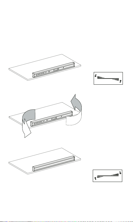
end of the surface as higher by the same amount of bars, plus or minus one
bar. Taking the same example, the display should now show the center bar
with two bars on top on the right side of the display and two bars on the bot-
tom on the left side of the display (Figure 8 below).
If this is not the case, the level is out of calibration and should be recalibrate
before being used.
Note: This process of turning the level end for end and comparing the
two indications relative to the surface is applicable to all levels, including bub-
ble levels.
Figure 6: Checking the LaserVision in One Direction
Figure 7: Turning the LaserVision End-for-End
Figure 8: Checking the LaserVision in the Other Direction
CCaalliibbrraattiinngg tthhee LLaasseerrVViissiioonn
The LaserVision's level module can be re-calibrated at any time to the original fac-
tory specifications to ensure precision.
6
NOTES: 1. The calibration process must be done on a solid, flat surface that is rea-
sonably level (when calibrating the level axes) or reasonably plumb (when calibrat-
ing the plumb axes). If the surface is too far from true level or plumb, “Out of
Range“ will appear on the LCD. If this indication appears, move the LaserVision to
a surface that is closer to level or plumb.
2. There is a cluster of four arrows at the top of the LCD display. These arrows
indicate which axes are not calibrated. They will appear after the unit has lost its
calibration which is normally after the batteries have been dead or removed for
sometime. During the calibration process, as noted below, the arrow corresponding
to the axis being calibrated will at various times blink, and finally, after calibration
is complete, will disappear. After all four axis have been calibrated, none of the cali-
bration arrows will be showing. If one or more of the arrows are showing, the
corresponding axis is not calibrated, and the LaserVision cannot be used
in this axis until it is calibrated.
3. For better accuracy, align the level with an edge of the surface or a line on the
surface when calibrating so you can maintain the same location easily.
4. The LaserVision must be in the standard mode (with no slope indicators or "AT"
across the bottom of the LCD) in order to calibrate properly. It will not calibrate in
a preset slope mode and will only memorize the current slope in "AT" mode.
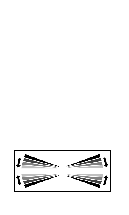
Calibrating to Level
• Place the LaserVision on a flat, solid, relatively level surface (see note (1) above).
• Press and hold the ON/OFF button for about three seconds, until the bars start
moving up and down (Figure 9 below) and an audio tone sounds. The axis
arrow and the number 1 will blink while the unit is calibrating the first position.
• When the indicators stop moving and the second audio tone sounds, the
number 2 will appear. Rotate the unit end for end (Figure 10, page 8).
• Place the level in the same location.
• Press and release the ON/OFF button once again and wait for the calibration
indicators to stop moving, the axis arrow to disappear, and the final audio tone
to sound. This axis is now calibrated.
• Flip the level over and calibrate the opposite surface of the level by following
the same procedure. Both level axis arrows should now have disappeared.
Figure 9: Calibration Display
7
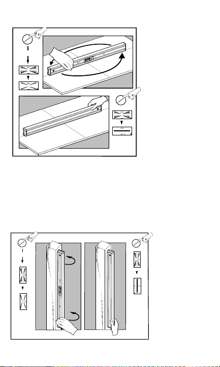
Figure 10: Calibrating to Level
Calibrating to Plumb
• Place the LaserVision against a stable, nearly vertical surface (See note (1) above).
• Press and hold the ON/OFF button for about three seconds until the bars start
moving up and down (Figure 9, page 7) and an audio tone sounds. The axis
arrow and the number 1 will blink while the LaserVision is calibrating the first
position.
• When the indicators stop moving and the second audio tone sounds, the number 2
will appear. Rotate the LaserVision 180 degrees while keeping the same end up
(Figure 11 below).
8
1a
A
B
A
B
1b
off
on
3 sec
off
on
A
B
2b
A
2a
B
off
on
3 sec
off
on
Figure 11: Calibration to Plumb

• Place the level in the same location.
• Press and release the ON/OFF button once again and wait for the calibration
indicators to stop moving, the axis arrow to disappear, and the final audio tone to
sound. This axis is now calibrated.
• Rotate the level end for end and calibrate the other plumb direction by following the
same procedure. Both plumb axis arrows should now have disappeared.
Allen Wrenches
The LaserVision comes with two allen wrenches packed in the end cap opposite
the laser. They can be stored there. When replacing the batteries, use the larger
3/32" allen wrench to remove the two front screws that hold the level module in
place. When aligning the laser, use the smaller 5/64" allen wrench to turn the
calibration screw.
Calibrating the LaserVision’s Laser
Although calibrated when leaving the factory, the LaserVision's laser can be eas-
ily recalibrated to the original factory specifications to ensure precision.
• In order to check or calibrate the laser module, place the LaserVision level on
a flat, stable surface with a target area located approximately 50 ft. (15 m)
away (Figure 12, page 10).
NOTE: The surface need not be level.
• Turn on the laser and mark the position of the center of the laser spot on the
remote target, see point 1 (P1).
• Turn the LaserVision over.
• Return to the target area and mark the new position of the center of the spot,
see P2. If the second mark is above the first, then the calibration screw (which
is the screw closest to the center, on the bottom of the LaserVision) should be
turned clockwise using the smaller 5/64" Allen wrench provided in the end
cap opposite the laser. If the second mark is below the first, then turn the
calibration screw counter-clockwise (Figure 13, page 11). Adjust the calibra-
tion screw until the laser spot is halfway between the two marks, see P3.
NOTE: Do not turn the screw closest to the end as it will disassemble the laser
unit and invali date your warranty.
• Return the LaserVision to the upright position and check the spot location.
The laser spot should match the midpoint. If it does not, redo the above steps
until there is no change when the level is turned over.
NOTE: Do not turn the screw closest to the laser end. This screw keeps the laser
module in place. If this screw is turned, your warranty will no longer be valid.
9
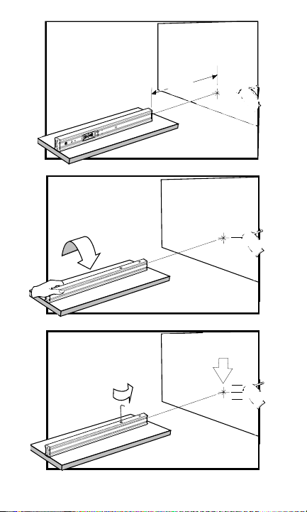
Figure 12: Calibrating the Laser
10
P3
P2
P1
P2
P1
~50ft.
P1
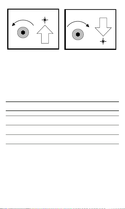
Figure 13: Aligning the Laser Spot
Finding Level and Plumb
The LaserVision features four segmented bars which indicate the angular
proximity of the LaserVision to level or plumb. (See Table I for Working Precision
Display.) The arrows displayed on both sides of the segment bars further indicate
which way to rotate the LaserVision to reach level or plumb. When level or plumb
is found, the LCD indicates a single bar and sounds an audio tone (unless the
sound has been turned off).
Working Precision Display:
Deviation from Level or Plumb: Maximum (Typical)
LCD
Segment Inches/100 Feet mm/m Degrees
Center Bar 0.50 in.(0.25 in.) 0.42(0.21) 0.02(0.01)
1st Bar
from Center 1.00 in.(0.50 in.) 0.83(0.42) 0.05(0.02)
2nd Bar
from Center 2.00 in.(1.00 in.) 1.66(0.83) 0.10(0.05)
3rd Bar
from Center 4.00 in.(2.00 in.) 3.04(1.66) 0.17(0.09)
Table I
Using the Laser
• Turn on the LaserVision and adjust to level or plumb.
• Push the laser power button located on the laser end cap (Figure 5, page 5).
When the laser is on, the button glows red.
• Point the LaserVision in the desired direction.
• Then mark the position of the laser spot.
NOTE: 1. Since the laser spot gets larger as it gets further from the LaserVision,
to ensure maximum accuracy, be sure to always mark the center of the spot.
2. The laser spot is projected from the center of the laser end cap and
is one inch from either top or bottom surface of the level. Be sure to
compensate for this one-inch difference.
11
CW
CCW
 Loading...