

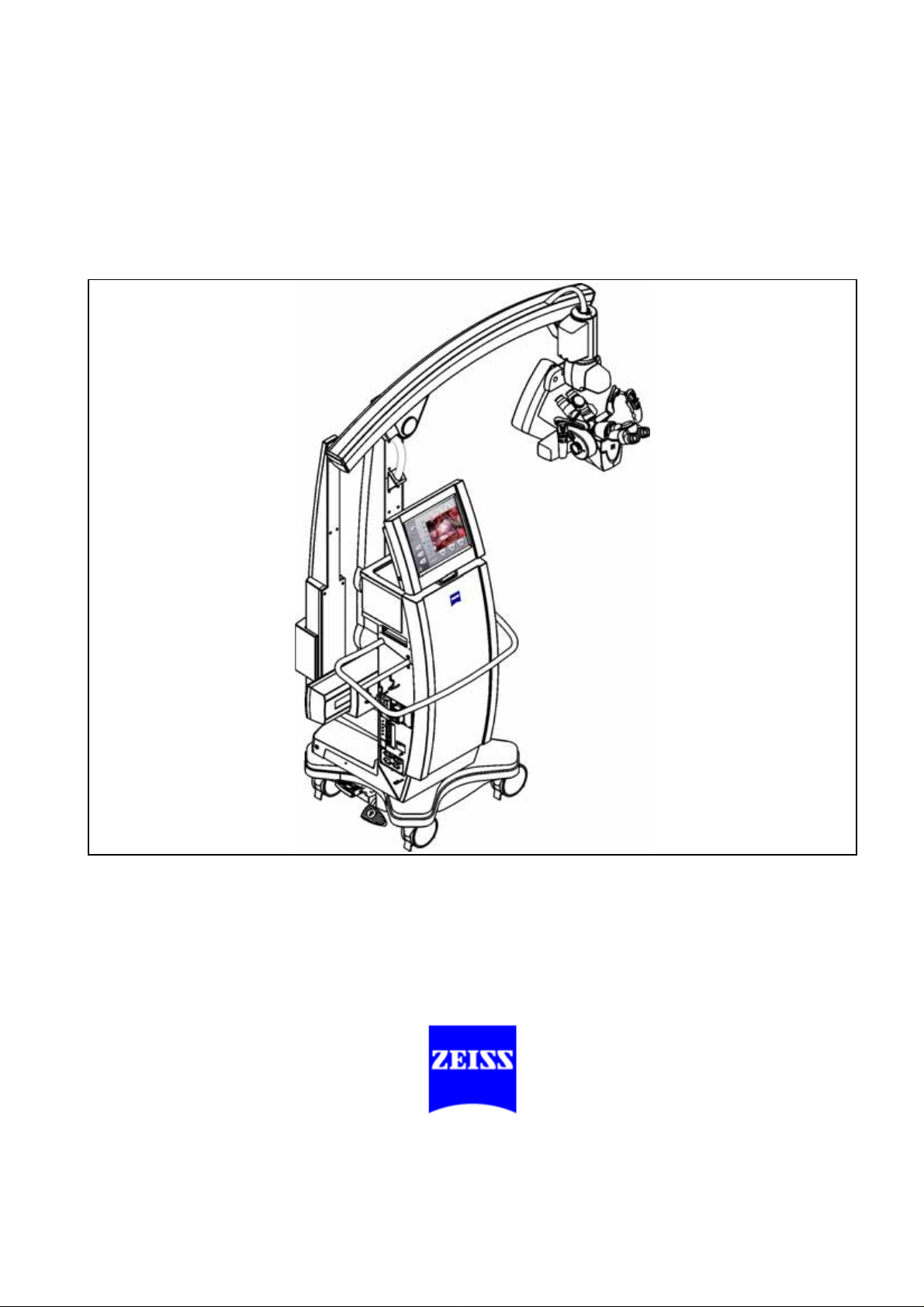
Page 1
OPMI® Pentero
Software Release 2.20 / 2.21
®
Instructions for use
G-30-1458-en
Issue 11.1
Printed on 18. 02. 2009
Page 2
2
Key to symbols
Different symbols used in this manual draw your attention to safety aspects and useful tips. These symbols are explained in the following.
Warning!
The warning triangle indicates potential sources of danger which may
constitute a risk of injury for the user or a health hazard.
Caution:
The square indicates situations which may lead to malfunction, defects,
collision or damage of the system.
FLOW 800 SW 2.21
Note:
The hand indicates hints on the use of the system or other tips for the
user.
Read the user manual!
®
OPMI
GmbH
and Pentero® are registered trademarks of Carl Zeiss Surgical
.
AutoDrape™, Superlux, FlexiTrax™, MultiVision™ and FLOW™ 800
are trademarks of Carl Zeiss Surgical GmbH.
FLOW 800 software release 2.21 is not an update, but a software upgrade
for the IR800 option of OPMI Pentero for the analysis of inf rared video angiography.
Upgrading is only possible for systems with serial number 6631402450
and higher and with software version 2.20.
G-30-1458-en OPMI® Pentero® Software Release 2.20 / 2.21 Issue 11.1
Printed on 18. 02. 2009
Page 3

Contents
Software Release 2.20 / 2.21 1
– Key to symbols 2
– FLOW 800 SW 2.21 2
Functions at a glance 9
– OPMI Pentero 10
– What to do in an emergency 12
Safety 15
– Protective measures for IT systems and networks 16
– Notes on installation and use 17
– Risk of burn injuries caused by high
illumination intensity 23
– Safety devices of the suspension system 26
– Warning labels and notes 28
Description 33
OPMI Pentero 34
– Intended use 34
– Special properties 36
– Surgical microscope and laser micromanipulator 38
– Injecting video images in the surgical microscope 39
– Injecting navigation information in the surgical microscope *) 40
– Overall system configuration 41
– Configuration options 44
Central user interface (touchscr een) 46
– Main menu 50
Controls and connections 52
– Binocular tubes and eyepieces 60
– Handgrips 64
– Superlux 330 illumination system 66
– Operating principle of the additional illumination 68
G-30-1458-en OPMI® Pentero® Software Release 2.20 / 2.21 Issue 11.1
Printed on 18. 02. 2009
Page 4

– Autofocus (focusing aid) 69
– Drape vacuum system 70
– Stand base /FlexiTrack™ system 72
– Connector panel 76
Connecting navigation systems 80
Preparations for use 85
– Relocating the unit 86
Assembling the system 88
– Configurations 88
– Mounting the tube and the eyepieces 90
– Attaching documentation / coobservation equipment 92
– Mounting the mouth switch (option) 94
– Adjusting the position of the handgrips 98
– Attaching sterile drapes 100
– Positioning the system at the operating table 102
– Starting the system 104
– Configuring the handgrips 106
Balancing the system 110
– Adjusting the surgical microscope 115
– USER menu / login 116
– Activating IT system rights and data protection 120
– Configuration menu (CONFIG) 124
Operation 163
Checklist 164
Procedure 167
– Working with the surgical microscope 167
– Comfortable control via the mouth switch (pivoting) 168
– Working with the data injection system 170
Patient Files menu (PAT-FILES) 174
– Managing patient data 174
– Viewing patient data 186
– Viewing patient images 188
– Editing images 192
G-30-1458-en OPMI® Pentero® Software Release 2.20 / 2.21 Issue 11.1
Printed on 18. 02. 2009
Page 5

– Saving 196
– Storing patient data on CD/DVD 198
– Storing patient data on a USB stick 202
What to do in an emergency 208
– Illumination failure - changing the xenon lamp 208
– Failure of the zoom function 210
– Failure of the focusing function 211
– Failure of the magnetic brakes 212
– Touchscreen failure 212
– Failure of the line voltage 212
– Error messages in the data injection system 213
– Failure of all control functions (Emergency mode) 214
– Individual magnetic brakes are blocked
(OPMI can not be moved at all or only to a limited extent) 215
Maintenance/Service 217
– Trouble-shooting 218
– Service Contract (Option) 219
– Starting Remote Service 220
– Changing the lamp module 222
– Recommended cleaning method 224
– Sterile drapes 225
– Ordering data 226
– Spare parts 227
– Accessories 228
– Disposal 230
Technical data 231
– OPMI Pentero 232
– 3 CCD PAL video camera, mono and stereo (version 1) 237
– 3 CCD NTSC video camera, mono and stereo (version 1) 238
– 3 CCD PAL video camera, mono and stereo (version 2) 239
– 3 CCD NTSC video camera, mono and stereo (Version 2) 240
– Ambient requirements 241
– Changes to the system 241
G-30-1458-en OPMI® Pentero® Software Release 2.20 / 2.21 Issue 11.1
Printed on 18. 02. 2009
Page 6

Digital video recording (option) 243
Digital video recording (option) 244
– Description 244
– Video clips 248
– Editing video clips 250
– Merging video clips 256
INFRARED 800 fluorescence module
(option) 261
Integrated INFRARED 800 (IR 800) fluorescence module 262
– Intended use 262
– Description 266
– Connecting an external monitor (recommended option) 276
– INFRARED 800 settings before every surgical procedure 278
– Checklist for the IR 800 function test 279
Procedure 280
FLOW 800 (option) 287
Normal use 288
Description 292
– General configuration 292
– Configuring INFRARED 800 296
– Activating FLOW 800 298
– Description of INFRARED 800 300
– Description of FLOW 800 306
Preparations for use 318
– Connecting an external monitor (recommended option) 318
– INFRARED 800 settings before every surgical procedure 320
– Checklist for the IR 800 function test 321
Procedure 322
– SETUP phase 322
– RECORD phase 324
– PLAYBACK phase 326
– FLOW 800 processing phase 328
G-30-1458-en OPMI® Pentero® Software Release 2.20 / 2.21 Issue 11.1
Printed on 18. 02. 2009
Page 7

BLUE 400 fluorescence module (option) 339
Integrated BLUE 400 (BL 400) fluorescence module 340
– Intended use 340
– Description 344
BL 400 checklist 348
DICOM (option) 351
DICOM 352
– Intended use 352
– Conformance Statement 352
– Configuring the network connection 356
– Further information on the Ethernet connection 362
– Connection test 364
– Configuring the DICOM connection 366
– Adding, editing and deleting a DICOM server 366
– Configuring the DICOM function 368
– Defining the maximum video export size to network serv ers 372
– Error messages during system configuration 376
– Importing patient data sets (from RIS systems) 378
– Importing patient data sets (from PACS system) 380
– Loading patient data 382
– Exporting DICOM data to a PACS 390
HDTV camera system (option)
(option) 393
393
HDTV camera system for OPMI Pentero (option) 394
– Intended use 394
– Configuration 395
– Attaching the HDTV components 396
– Connecting the HDTV camera system 398
– Microscope positions with the HDTV camera system 400
Checklist for HDTV camera system for OPMI Pentero 401
Cleaning the HDTV components 403
G-30-1458-en OPMI® Pentero® Software Release 2.20 / 2.21 Issue 11.1
Printed on 18. 02. 2009
Page 8

Index 405
G-30-1458-en OPMI® Pentero® Software Release 2.20 / 2.21 Issue 11.1
Printed on 18. 02. 2009
Page 9

Functions at a glance 9
Functions at a glance
OPMI Pentero 10
What to do in an emergency 12
G-30-1458-en OPMI® Pentero® Software Release 2.20 / 2.21 Issue 11.1
Printed on 18. 02. 2009
Page 10

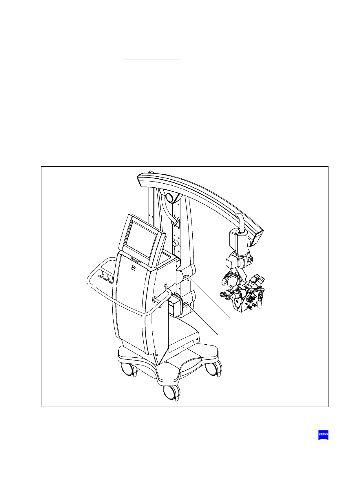
10 Functions at a glance
OPMI Pentero
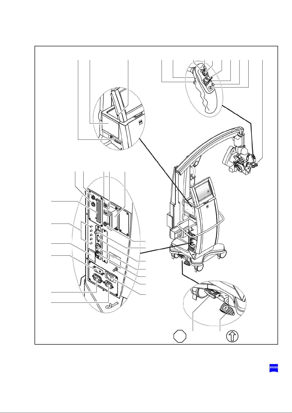
1 Adjusting the microscope page:115, 124ff
2 Programmable button (factory setting: illumination +) page:108, 136
3 Programmable button (factory setting: illumination -) page:108, 136
4 Setting focus +/- (configurable: setting zoom +/-) page:108, 136
5 Setting zoom +/- (configurable: setting focus +/-) page:108, 136
6 Joystick: moving the OPMI in the XY direction page:136, 140
7 Programmable button (factory setting: autofocus) page:108, 142
8 Programmable button (factory sett ing: trigger photo) page:106, 136
9 Unlocking/locking magnetic brakes for selected axes (SB) page:108, 142
10 Unlocking/locking magnetic brakes for all axes (AB) page:106, 142
11 Connecting USB storage media page:200ff
12 Changing the xenon lamp / lamp module page:208, 222
13 CD/DVD drive page:196
14 Connecting an external navigation system page:78, 80ff,
15 Connecting a LAN cable page:78
16 Connecting a modem page:78
17 Connecting a foot rocker switch page:78
18 AUX port for controlling an external device page:78, 234
19 Connecting a foot control panel, foot switch or operating chair page:78
20 Automatic circuit breakers page:78
21 Emergency switch (remove cover) page:200
22 Rated voltage indicator page:76
23 Power outlet page:76
24 Power inlet (115/230V) page:76
25 Video input port (e.g. for connecting an endoscope camera) page:78
26 Video signal output port BNC (VBS) page:76, 276
27 Video DV output port page:76
28 Connecting an external monitor (VGA/RGB) page:76
29 Connecting an external monitor (Y/C) page:76, 276
30 Connecting the system to potential equalization page:76
31 Power switch; powering up the system page:76
32 Locking pedal - press to lock stand in position page:74, 86
33 Setting straight-ahead travel page:74 ,86
154
G-30-1458-en OPMI® Pentero® Software Release 2.20 / 2.21 Issue 11.1
Printed on 18. 02. 2009
Page 11
Functions at a glance 11
19
812 765432 191013 11
32 33
STOP
18 17 16 15 14
20
21
22
23
24
25
26
27
28
29
30
31
G-30-1458-en OPMI® Pentero® Software Release 2.20 / 2.21 Issue 11.1
Printed on 18. 02. 2009
Page 12

12 Functions at a glance
What to do in an emergency
1Failure of illumination - changing the xenon lamp:
• Open flap (1)
• Change the xenon lamp by pulling grip (8) page 208
2 Failure of the zoom function:
• Manually adjust the magnification using zoom knob
(2). If the motorized zoom function becomes active of
its own accord (e.g. travels to the stop), set emergency
switch (7) to the emergency mode (position 2).
3 Failure of the focusing function:
• Manually adjust the working distance using focusing
knob (3). If the motorized focusing function becomes
active of its own accord (e.g. travels to the stop), set
the emergency switch to the emergency mode (position 2)
4 Some of the magnetic brakes are blocked:
page 210
page 211
• Switch off power switch (4). As soon as the blue
screen appears (approx. 10 sec), switch the system
back on.
The OPMI functions (zoom, focus, light and magnetic
brakes) are available again after approx. 15 seco nds.
The computer and touchscreen, however, are disabled.
If the magnetic brakes are still blocked:
• Hol d the microscope on its body (not on the handgrips )
and position it manually by over coming the br aking effect.
5 Failure of the touchscreen:
• Do not under any circumstances touch the touchscreen, since this can result in changes to settings and
parameters. Zoom, focus, i llumin ati on a nd brakes can
still be operated.
6 Error messages in the data injection system:
• System errors are displayed in the microscope's integrated data injection system. You can delete these
messages by acknowledgement using the joystick of
the right handgrip (pushbutton) or the t ouchscreen.
page 215
page 212
page 212
G-30-1458-en OPMI® Pentero® Software Release 2.20 / 2.21 Issue 11.1
Printed on 18. 02. 2009
Page 13
Functions at a glance 13
5
1
4
7
2
3
8
6
7 Failure of control functions:
• Set emergency switch (7) to the emergency mode (position 2). Zoom and focus must then be operated manually (2, 3).
• Hold the microscope on its body (not on the handgri ps)
and position it manually by overcoming the braking effect.
page 214
G-30-1458-en OPMI® Pentero® Software Release 2.20 / 2.21 Issue 11.1
Printed on 18. 02. 2009
Page 14

14 Functions at a glance
G-30-1458-en OPMI® Pentero® Software Release 2.20 / 2.21 Issue 11.1
Printed on 18. 02. 2009
Page 15

Safety
Safety 15
Protective measures for IT systems and networks 16
Notes on installation and use 17
Risk of burn injuries caused by high
illumination intensity 23
Safety devices of the suspension system 26
Warning labels and notes 28
G-30-1458-en OPMI® Pentero® Software Release 2.20 / 2.21 Issue 11.1
Printed on 18. 02. 2009
Page 16

16 Safety
The device described in this manual has been desi gned and teste d in accordance with Carl Zeiss safety standards as well as German and international standards. This guarantees a high degree of instrument safety.
The system described in this user manual has been designed in compliance with the requirements of:
–EN –IEC –UL –CSA
In accordance with Directive 93/42/EEC for medical devices, the complete quality management system of the company Carl Zeiss Surgical
GmbH, 73446 Oberkochen, Germany, has been certified by DQS Deutsche Gesellschaft zur Zert ifi zierung von Manag ementsy stemen GmbH, a
notified body, under registration number 250758 MP23.
– In compliance with Directive 93/42 /EEC, the basic configuration of
this system is a class I device.
Equipped with the Integrated Fluorescence Module option, it is a
class IIa device.
– For USA: FDA classification: Class I.
We would like to provide you with information about safe ty aspects which
must be observed when handling this device. This chapter contains a
summary of the most important information concerning matters relevant
to instrumen t sa f e ty .
Important safety information has been incorporated in this manual and is
marked with a warning triangle accordingly. Please give this information
your special attention.
The correct use of the sy stem is absolutel y vital for s afe operation. Ple ase
make yourself totally familiar wi th the contents of this manual prior to star tup of the instrument. Please also observe the user manuals of any additional equipment. Further information i s available from our service department or from authorized representatives.
• Please observe all applicable accident prev ention regulations.
• The instrument must be connected to a special emergency backup
line supply in accordance with the regulations or directives which ap-
ply in your country.
Protective measures for IT systems and networks
The user (or IT officer) is responsible for ensuring that no viruses are
transferred to the OPMI Pentero system via the network connection.
G-30-1458-en OPMI® Pentero® Software Release 2.20 / 2.21 Issue 11.1
Printed on 18. 02. 2009
Page 17

Safety 17
It is the user's responsibility to ensure that the media used for data communication (CD, DVD, USB stick) are free from viruses.
Responsibilities for data protection and inf ormation security
The user (or IT officer) must ensu re that the national laws and regulat ions
relating to data protection are complied with.
The operators of IT systems and IT networks are responsible for the definition of the safety standards required, i.e. for the creation of the necessary technical and organizational framework.
Definition of terms
Personal data means any inform ation concerning the per sonal or material
circumstances of an identified or i dentifiable individual. All data directly attributable to a person ( employee, customer, supplier), e.g. marital status,
type of employment, religion, income, etc., must be protected.
Data processing means the storage (entry, recording or preservation),
transfer (transmission to t hird parties outside the organization), modification (alteration of the substance, including anonymization and aliasing),
erasure (deletion) and blocking (labeling so as to restrict further
processing or use) of data.
Use means any utilization of data (e.g. in-house transmission).
Recipient means any person or body receiving data. Third party means
any person or body other than the controller (legal entity). The transmission of data to third parties is deemed to constitute data transfer.
Notes on installation and use
Safe working order
• Do not operate the equipment contained in the delivery package in
– explosion-risk areas,
– the presence of inflammable anesthetics or volatile solvents such
as alcohol, benzine or similar chemicals.
• Do not station or use the instrument in damp rooms. Do not expose
the instrument to water splashes, dripping water or sprayed water.
• Immediately unplug any equipment that gives off smoke, sparks or
strange noises. Do not use the instrument unt il our ser vice rep rese ntative has repaired it.
G-30-1458-en OPMI® Pentero® Software Release 2.20 / 2.21 Issue 11.1
Printed on 18. 02. 2009
Page 18

18 Safety
• Do not place any fluid-filled c ontainer s on t op of the ins trume nt. Make
sure that no fluids can seep into the instrument.
• Do not force cable connections. If the male and female parts do not
readily connect, make sure that they are appropriate for one another.
If any of the connectors are damaged, have our servi ce representative
repair them.
• Potential equalization: If requested, the instrument can be incorporated into potential equalization measures.
• Do not use a mobile phone in the vicinity of the equipment because
the radio interference can cause the equipment to malfunction. The effects of radio interference on medical equipment depend on a number
of various factors and are therefore entirely unforeseeable.
Warning!
Do not use the video images for diagnostic purposes, as the video cameras and the monitor have not been calibrated. The visualized images
may therefore include deviations in shape, contrast and color.
The company Carl Zeiss shall not be liable fo r any defective CD/DVD and
any resultant loss of images.
• If you have burnt important images on a CD/DVD, we recommend you
to create a backup of this CD/DVD using a PC.
Caution:
The company Carl Zeiss accepts no liability for any loss of pati ent, image
and video data as well as system or user-specific configurat ion data. If required, arrange for patient, image and video data as well as all system
settings to be backed up by your IT administrator on a regular basis.
In the event of repairs by Carl Zeiss service staff, the recovery of patient,
image, video and configuration data is no longer
possible.
• Modifications and repairs on these instruments or instruments used
with them may only be performed by our service representative or by
other authorized persons.
• The manufacturer will not accept any liability for damage caused by
unauthorized persons tamp ering wi th the i nstrument ; this will also f orfeit any rights to claim under warranty.
• Over longer distances (e.g. removal, return for repair, etc), the instrument may only be transported in the original packaging or in special
return packaging. Please con tact your dealer or the Carl Ze iss service
team.
• Use this instrument only for the applicati ons described.
G-30-1458-en OPMI® Pentero® Software Release 2.20 / 2.21 Issue 11.1
Printed on 18. 02. 2009
Page 19

Safety 19
• Only use the instrument with the accessories supplied. Should you
wish to use other accessory equipment, make sure that Carl Zeiss or
the equipment manufacturer has certified that its use will not impair
the safety of instrument.
• Only personnel who have undergone training and instruction are allowed to use this instrument. It is the responsibility of the customer or
institution operating the equipment to train and instruct all staff using
the equipment.
• Keep the user's manuals where they are easi ly acce ssible at all ti mes
for the persons operating the instrument .
• Never look at the sun through the binocula r tube, the obje ctive lens or
an eyepiece.
• Please do not pull at the power cable or any other connecting cables.
• This system is a high-grade technological product. To ensure optimum performance and safe working order, we recommend having th e
system checked by our service representative on a regular basis.
If a failure occurs which you cannot correct with the help of this user
manual, attach a sign to the system stating that it is out of order and
contact our service representative.
• Observe the labels showing the symbol "Risk of crushing“!
Notes on EMC (electromagnetic compatibility)
The system meets the EMC requirements of IEC 60601-1-2. During use
of the system, the precautionary measures concerning EMC listed below
must be observed.
Only use accessories that have been approved by Carl Zeiss for this
system.
Do not use any portable or mobile high frequency communic ation devices
in the vicinity of the system, as t his may le ad t o an impai rment of i ts f unction.
The system complies with the limits for a Class A devic e concerning radio
frequency emission. However, the possibility of interference to high frequency receiving devices (e.g. TV sets or radios) being used in the surroundings cannot be ruled out. If interference of this type occurs, please
inform your Carl Zeiss Service.
G-30-1458-en OPMI® Pentero® Software Release 2.20 / 2.21 Issue 11.1
Printed on 18. 02. 2009
Page 20
20 Safety
Interference radiation
To ensure permissible operation in conjuncti on with neuromonitor ing systems, an optional upgrade kit is available which significantly reduces the
system's permissible interference radiation for these sensitive measurements (see Accessories, neuromonitoring upgrade kit, page 229)
Requirements for operation
Note:
– Please also take note of the latest Release Notes about the installed
software version. These are part of the delivery package when the
system is supplied. After a software update, you will always receive
the latest version.
Our service representative or a specialist authorized by us will install the
instrument. Please make sure that the following requirements for operation remain fulfilled in the future:
– All mechanical connections (details in the user's manual) which are
relevant to safety ar e properly connected and s crew connections tight-
ened.
– All cables and plugs are in good working condition.
– The instrument is plugged into a power outlet which has a properly
connected protective ground contact.
– The power cord being used is the one designed for use with this in-
strument.
Warning!
For safety reasons, the system must only be used when correctly balanced. Despite the autobalance function, it may happen in exceptional
cases that the surgical microscope is not correctly balanced.
With an incorrectly balanced system, brake release may lead to uncontrolled movements of the suspension system. For this reason, the balancing procedure and the subsequent test must not be performed above
the patient and only at a safe distance from other persons and instruments.
To check correct balancing of the system, l oosen the brakes while holding
the microscope tightly at b oth handgri ps. If t he system has b een correctl y
balanced, the surgical microscope can be moved almost eff o rtlessly.
Repeat the autobalance procedure, if required.
G-30-1458-en OPMI® Pentero® Software Release 2.20 / 2.21 Issue 11.1
Printed on 18. 02. 2009
Page 21
Safety 21
R
1
.
5
m
R
5
9
"
Connection to data networks
Activities in the data network may interfer e with the system. We theref ore
recommend that you disconnect the system from data networks before
surgery.
The network connector must be adequatel y contact -prot ected , e.g. mad e
of plastic material.
The cable and connector of the network connection must at least comply
with Cat-5e EIA/TIA-568A-5, i.e. the more recent Class D values from
ISO/IEC 11801:2002 or EN 50173-I:2002.
Warning!
Data transmitted by the system into the data network or data available in
the data network risk to be corrupted or transmitted incompletely. Therefore, no liability can be accepted for the corr ectness of the data.
The operator of the data network is responsible for compliance with the
legal requirements regarding data security and for the protection of personal rights.
Connection of equipment from other manufacturers
If you operate this system within the patient area* in conjunction with devices from other manufacturers which do not comply with the IEC606011 standard, you must ensure that either the third-party devices are powered via an isolating transformer, or that each of them is connected with
the central ground system via an additional ground terminal (potential
equalization).
The leakage current may increase if the system is connected with other
devices. The resulting new system must comply with the EN 60601-1-1
standard (Safety Requirements for Medical-Electrical Systems).
*Fig.: Patient area
G-30-1458-en OPMI® Pentero® Software Release 2.20 / 2.21 Issue 11.1
Printed on 18. 02. 2009
Page 22

22 Safety
Before every use and after re-equipping the instrument
• Make sure that all ”Requirements for operation” are fulfilled.
• Go through the checklist (see chapter "Operation“ or the index).
• Re-attach or close any covers, panels or caps which have been re-
moved or opened.
• Please pay special attention to labels on the uni t (warning triangle with
an exclamation mark, warning labels and notes) .
• Do not cover any ventilation openings.
For every use of the instrument
• Using the locking pedal on the base, secure the stand in position.
Make sure that the stand is stable and cannot roll away.
• Make sure that nothing obstructs the touch-sensitive area of the
touchscreen. Prevent objects from exerting pressure on the touch-
sensitive area of the touchscreen.
• Any kind of radiation has a detrimental effect on biol ogical tissue. This
also applies to the light illuminat ing the surgical f ield. Please therefor e
reduce the brightness and duration of illumi nation on the surg ical fiel d
to the absolute minimum required.
•Never
use xenon illumination for ophthalmic procedures.
• Make sure that no xenon light enters the patient's eyes.
• The illumination intensity required depends on the type of application
involved. Make sure that no tissue damage is caused by excessive il-
lumination intensity.
Connection and operation of navigation systems
Only systems from authorized manufacturers may be connected and
used on the navigation interface of OPMI Pentero (see page 80). Authorized manufacturers are companies or institutions with which Carl Zeiss
Surgical has concluded an Open Interf ace Contract and for which the use
of the integrated navigat ion i nte rface wi th data i nje ction system has been
licensed.
Please observe the user manual for the connected system.
G-30-1458-en OPMI® Pentero® Software Release 2.20 / 2.21 Issue 11.1
Printed on 18. 02. 2009
Page 23

Safety 23
Risk of burn injuries caused by high
illumination intensity
General
The OPMI Pentero is equipped with a powerful xenon illumination system.
Excessive illumination intensities may lead to third-degree burns, if used
improperly.
The risk of burns is influenced by several different factors:
System-related factors:
– The wavelength range is limited by fi lters to t he visible ran ge between
400 nm and 700 nm (between 400 nm and 780 nm in the IR 800 mode
only). These filters remain stable over a very long period of time and
cannot be exchanged by the user.
– With increasing age of the light source, the actual illumination intensi ty
delivered at the respective setting decreases. When the light source
is finally replaced, the illumination intensity increases again to the
high, original value.
Surgery-related factors:
– The selected intensity of the light source is a major factor for the risk
of injury. It should always be set to the minimum required for the surgical procedure to be performed.
– The size of the illuminated field influences the risk of injury in two dif-
ferent ways:
– If the illuminated area has a large diameter, skin areas are illumi-
nated that are not closely monitored by the surgeon and are not
sufficiently irrigated. These areas are particularly prone to injury.
Injuries can be prevented by adjusting the diameter of the illuminated field to the smallest size needed for the respective procedure.
– Reducing the illuminated field increases the intensity because the
light becomes more focused. The light intensity should therefore
be reduced, if possible, as soon as the diamet er of the illuminate d
area is reduced.
– A long surgical procedure increas es the risk of injury, in particu lar if a
standard procedure takes considerably longer t han usual.
– Injuries in the peripheral area can be prevented by covering this area
with wet, sterile gauze.
G-30-1458-en OPMI® Pentero® Software Release 2.20 / 2.21 Issue 11.1
Printed on 18. 02. 2009
Page 24

24 Safety
– You should also take int o account that some ar eas of the body may be
more sensitive than others.
– Certain preparations of the surgical field, local vasoconstrictive medi-
cations and incision drapes may also resu lt in a higher risk of injury.
Patient-related factors:
– The general condition of a patient's health may contribute to the risk
of injury.
– The skin type may also play a major role in this respect.
– Certain medications affect the sensitivity to light.
Recommendations
Due to the large number of different factors involved and the lack of scientific publications on this topic, Carl Zeiss cannot provide guidance on
acceptable intensities and exposure durations. However, the OPMI
Pentero has several features that can help the user to reduce the risk of
burns:
– The start value of the light intensity can be set to a low value (page
134).
– The spot function permits y ou to reduce the size of t he illuminated field
to the area observed during the procedure (page 66).
– You can then set the light int ensity to the val ue required for the p roce-
dure using the buttons on the handgrip or foot control panel. Please
note that the use of t he spot i llumination system incr eases th e intensi-
ty as the size of the illuminated field decreases. Therefore adjust the
light intensity after changing the diameter of the illuminated field.
– If the system features Automatic Light Field Limitation, this function
has been activated at the factory and should not be deactivated.
In systems without automatic light field limitation, the Light Intensity
Control function has been activated at the factory and should not be
deactivated.
– The magnification level i s us ually in crea sed duri ng a proc edure, lead-
ing to a darker image and thus necessitating an increase in illumina-
tion intensity. If zoom-dependent brightness control has been
activated, it automatically compensates for this loss in image bright-
ness. (page 134)
– Switch off the light when the microscope is not used, and make sure
that it is not pointed at unprotected bare skin.
G-30-1458-en OPMI® Pentero® Software Release 2.20 / 2.21 Issue 11.1
Printed on 18. 02. 2009
Page 25

Safety 25
Please note that most burns affected the skin around the incision. The
most important measures to prevent burns are the reduction of the area
illuminated by spot illumination and covering the peri pheral area with wet
sterile gauze. The area of the incision should be constan tl y irrigated.
Final remark
Carl Zeiss recommends:
– Reduce the illumination of the surgical field to the extent required for
the patient's safety and for clear microscopic visualization.
The illumination intensity is preconfigured (factory settings) in such a
way that a warning is di splayed on t he touchs creen and in the dat a injection system when the threshold value of 25% is exceeded, informing the user of possible tissue damage
when the light intensity is too
high.
– Please note the warning and safety notes in the "Light“ configuration
menu (page 134).
– Reduce the exposure time to a minimum.
These measures should help t he s urgeon to r educe the r isk of phototo xic
injury of the patient.
After every use of the instrument
• Switch off the system at the power switch after every use.
G-30-1458-en OPMI® Pentero® Software Release 2.20 / 2.21 Issue 11.1
Printed on 18. 02. 2009
Page 26
26 Safety
Safety devices of the suspension system
Mechanical end stops
protect cables and the light guide against bending and stretching.
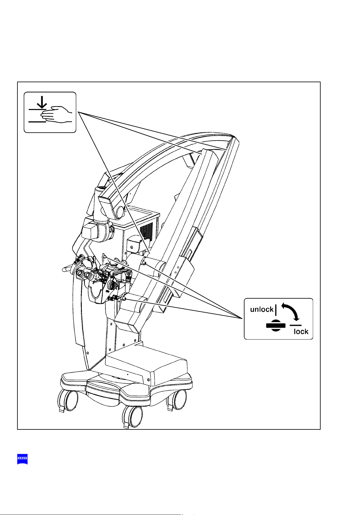
Transport locks (1)
for locking the axes in position during transportation.
Safety switch
The brakes will be locked if a spring or cable breaks. You can nevertheless finish surgery, as you can still move the surgical microscope by applying slight force.
Uninterruptible power supply (UPS)
A UPS is integrated in the syst em to ensure correc t operation in t he event
of short power failure. It powers the electronic system and the touchscreen, but not the light source.
Messages:
– Line power failure: in the event of li ne power failure, the system is
supplied for a short time. If no power is available for a prolonged
period, the system is shut down.
– Line power is back: the user is informed when line power is back
(Power OK), and all subsystems are re-initialized. This process
may take a few seconds.
Note:
In general, the system is ready for oper ation after power-up. A continuous
beep indicates extreme discharging of the USP. In this case, the system
should not be powered up for at least five minutes. After this time, you can
power up the system again for charging the UPS. For t he ini tial start up or
after long rest periods, we recommend the following: leave the poweredup system connected to line power for approx. 12 hours in order to fully
charge the UPS.
The system automatically tries to remedy problems in the control software. After several unsuccessful attempts, the system executes a PC
reset to restart the applicat ion. This restart ru ns automatically in the background and restores the full functionality of the system within approx. 2
minutes. All major basi c f unctions of the OPMI Pent ero remain fu ll y avai lable to the user during this time (operation of focus, zoom, light, brakes,
motorized XY movement)
.
Backup illumination
The lamp module contains two identical lamps. If lamp 1 fail s, a quick-action changer ensures that the li ght guide is supplied by lamp 2. The lamp
change does not impair the surgeon in his work.
G-30-1458-en OPMI® Pentero® Software Release 2.20 / 2.21 Issue 11.1
Printed on 18. 02. 2009
Page 27
Safety 27
1
1
1
Heat protection filter
The illumination system is equipped with a heat protection filter.
G-30-1458-en OPMI® Pentero® Software Release 2.20 / 2.21 Issue 11.1
Printed on 18. 02. 2009
Page 28
28 Safety
Laser
Austrittsöffnung
Laser
Aperture
Apertura
de Laser
Ouverture
Laser
O
P
M
I
P
e
n
t
e
r
o
Warning labels and notes
Caution:
Observe all warning labels and notes!
If any label is missing on your instrument or has become illegible, please
contact us or one of our authorized representatives. We will supply the
missing labels.
G-30-1458-en OPMI® Pentero® Software Release 2.20 / 2.21 Issue 11.1
Printed on 18. 02. 2009
Page 29
Safety 29
MANUFACTURED IN GERMANY BY
Carl Zeiss
Laserstrahlung
nicht in den Strahl
blicken
Laser Klasse 2
Pmax: <1mW
λ
635-645nm
nach EN 60 825-1:2002
Radiacion Laser
no mirar en
el rayo
Laser de classe 2
Pmax: <1mW λ 635-645nm
sequm EN 60 825-1:2002
Laser radiation
do not stare
into beam
Class 2 laser product
Pmax: <1mW
λ
635-645nm
as per EN 60 825-1:2002
Rayonnement Laser
ne pas regarder
dans le faisceau
Appareil a laser de classe 2
Pmax: <1mW
λ
635-645nm
conforme a EN 60 825-1:2002
Laser radiation
do not stare into beam
Power output 1 m W
wavelength 635-645 nm
class II laser product
FABRIQUE EN R. F. A. PAR
Carl Zeiss
O
P
M
I
P
e
n
t
e
r
o
DRAPE
Hier luftdicht abschließen
Make airtight here
Fermer hermétiquement ici
Cerrar herméticamente aquí
O
P
M
I
P
e
n
t
e
r
o
FLOW 800 Pentero
Carl Zeiss Surgical GmbH
302581-9250-000
SN 10xxxx
REF
Options:
INFRARED 800 NTSC
Carl Zeiss Surgical GmbH
302581-9246-000
SN 51xxxx
REF
INFRARED 800 PAL
Carl Zeiss Surgical GmbH
302581-9245-000
SN 51xxxx
REF
BLUE 400
Carl Zeiss Surgical GmbH
302581-9050-000
SN 50xxxx
REF
G-30-1458-en OPMI® Pentero® Software Release 2.20 / 2.21 Issue 11.1
Printed on 18. 02. 2009
Page 30
30 Safety
Labels: transport locks and risk of crushing
G-30-1458-en OPMI® Pentero® Software Release 2.20 / 2.21 Issue 11.1
Printed on 18. 02. 2009
Page 31

Safety 31
DVD
Labels: lamp change and DVD drive
G-30-1458-en OPMI® Pentero® Software Release 2.20 / 2.21 Issue 11.1
Printed on 18. 02. 2009
Page 32

32 Safety
G-30-1458-en OPMI® Pentero® Software Release 2.20 / 2.21 Issue 11.1
Printed on 18. 02. 2009
Page 33

Description
Description 33
OPMI Pentero 34
Intended use 34
Special properties 36
Surgical microscope and laser micromanipulator 38
Injecting video images in the surgical microscope 39
Injecting navigation information in the surgical microscope *) 40
Overall system configuration 41
Configuration options 44
Central user interface (touchscreen) 46
Main menu 50
Controls and connections 52
Binocular tubes and eyepieces 60
Handgrips 64
Superlux 330 illumination system 66
Operating principle of the addit ional illumination 68
Autofocus (focusing aid) 69
Drape vacuum system 70
Stand base /FlexiTrack™ system 72
Connector panel 76
Connecting navigation systems 80
G-30-1458-en OPMI® Pentero® Software Release 2.20 / 2.21 Issue 11.1
Printed on 18. 02. 2009
Page 34

34 Description
OPMI Pentero
Intended use
The overall system comprises a surgical microscope and a floor stand
containing the electronics and a graphic touchscreen with video display.
The OPMI Pentero is ideally suited for cranial and spinal applications in
neurosurgery, for ENT applications in the area of the auditory nerve and
the base of the skull. Fur ther fiel ds of applicati on include R&P pr ocedures
in accident surgery, R&P su rgery, and oral and maxi llo-facial surgery. The
system is also ideally suited for multidisciplinary use in microsurgery. It
has also been designed for surgical procedures in which an endoscope
and a surgical microscope are used simultaneously. The system is
equipped for the connection of navigation systems and for data communication with external network systems.
The system is intended for use in hospitals, clinics or other human medicine institutions.
The functions of the surgical microscope and of the suspension system
are controlled by the central control unit in the console. An interactive
graphic touchscreen permits you to confi gure all sett ings. You can trigger
these functions using the buttons on the handgrips or on a foot control
panel.
The system must only be operated by phys ic ians, nur ses and ot her medically trained OR staff who have received appropriate briefing and observe the instructions of the user's manua l. The installation conditions and
the use of the system must meet microsurgical requirements:
– low vibration
– dust-free environment
– level, horizontal positioning
– avoidance of extreme mechanical stress.
Warning!
– In line with its intended use, the sys tem must only be used on a patient
when it has been correctly balanced.
With an incorrectly balanced system, brake release may lead to uncontrolled movements of the suspension system. For this reason, the
balancing procedure and the subsequent test must not be performed
above the patient and only at a safe distance from other persons and
instruments.
G-30-1458-en OPMI® Pentero® Software Release 2.20 / 2.21 Issue 11.1
Printed on 18. 02. 2009
Page 35

Description 35
– The system must not be used for ophthalmic procedures.
Note:
– The system is not intended f or permanent data archiving. You can use
CDs/DVDs, a USB stick or an external hard drive for data backup. All
users are responsible for archivin g thei r own data.
If sufficient storage space is no longer available, the system informs
you that files no longer required should be archived or deleted.
Data can be deleted
by every subsequent user!
Note:
– Please also take note of the latest Release Notes about the installed
software version. These are part of the delivery package when the
system is supplied. After a software update, you will always receive
the latest version.
Note
on MediLive Video Tools:
The MediLive Video Tools software provides improved compatibility between your PC (Windows™ or MacOS™) and the video DVDs created
with OPMI
®
Pentero®.
Please install MediLive Video Tools on your PC if you notic e the following
problems:
– The computer cannot read the DVD content or the DVD is not identi-
fied because the UDF 2.0 disk format is not recognized.
– The video player or Office™ software is unable to play MPEG2 videos
as the MPEG2 decoder is missing.
One MediLive Video Tools CD is supplied as part of the digital video recording option.
The ZEISS cat. no. of this CD is 308203-8040-000.
G-30-1458-en OPMI® Pentero® Software Release 2.20 / 2.21 Issue 11.1
Printed on 18. 02. 2009
Page 36

36 Description
Special properties
– The surgical microscope features an integrated beamsplitter system
which can be set on the touchscreen (page 13 0) or on the microscope
(manual setting of sliding mirror posit ion; page 54) either as a symmetric optical system for face-to-face use, or for lat eral coobservat ion and
documentation.
– An autofocus system can be optionally used to focus the microscope
on an object within a working distance of 200 to 500 mm.
– The autofocus system focuses on the object at the press of a button
on the handgrip or foot cont rol un it, in combi nation with the br ake buttons. The point of reference is t he cen ter of t he fie ld of vi ew. If the object is in focus, the focus is visualized by two laser spots which meet
in the optical axis at the center of the field of view.
– The magnification ratio of the zoom system is 1:6.
– The system provides an image illuminated with optimum brightness,
maximum image contrast and additionally switchable, special illumi-
nation for lightenin g up shadows in narr ow channels. An int egrated di-
aphragm permits the depth of field to be set to two levels.
– Filters can be automatically swung into the observation and video
beam paths (for special applications such as fluorescence (option)).
– A high-grade 3-chip camera is integrated in the surgical microscope.
An additional camera for the stereo mode can be retrofi tted at any time
by our service representative.
– The surgical microscope is equipped with a fully integrated, digital
data injection system for navigation, video, PC, etc. (Multivision sys-
tem).
– The system is equipped for the connection of a navigation system.
– Video image injection combines endoscopy with classical micro-
scope technology.
– Quick image switchover between the microscope image and th e en-
doscope image using a handgrip button or foot control unit, making it
unnecessary for the surgeon to look up from the surgical fi eld.
– Video signal output: what the surgeon currently sees is v isualized on
an external monitor.
– Display of operating mode: every time you press the handgrip but-
ton or the foot control unit, the current mode is displayed for 5 seconds
in the form of text information superimposed on the current image.
G-30-1458-en OPMI® Pentero® Software Release 2.20 / 2.21 Issue 11.1
Printed on 18. 02. 2009
Page 37

Description 37
– Use in a navigation system *) possible via the navigation interface.
– Image superimposition for navigation purposes *): contours are
superimposed on the current video image.
– Image injection for navigation purposes *)
– Control of the graphic user interface, display of the touchscreen, con-
trol via the joystick mouse.
*) Only possible if a navigation system has been connected.
– The system can be connected to an existing hospital network for the
transfer or exchange of data (images, videos, audio files).
– The video images are visualized on the integrated color display, and
are visible in both eyepieces of the surgical microscope. The micro-
scope image is eclipsed by a shutter system for this purpose.
– At the press of a button (using the programmable handgrip button
(Multivision function) or the foot switc h), the integr ated shutter permi ts
rapid switching between the microscope image and the video image.
This means that the surgeon c an observe the endo scope image in the
eyepiece and need not look at an external monitor.
– The coobservation and documentation equipment of the surgical mi-
croscope always provides the image seen by the surgeon.
– The touchscreen or an external monitor also displays the image cur-
rently seen by the surgeon. This is either the microscope image re-
corded by the integrated camera of the surgical microscope, or - after
switchover - the image provided by a connected endoscope camera.
– An additional tiltable tube (option) can be mounted in a 180° position
to the tube for the main surgeon, allowing two surgeons to work face-
to-face.
– Important functions such as focu sing and zoom have been motorized
and can be controlled by the press of a button on the programmable
handgrips.
Warning!
When connecting instruments from other manufacturers, make sure that
safety is guaranteed regarding admissible ground leakage currents. The
admissible limit value of the ground leakage current present in the suspension system's power cord is 500 µA in compliance with EN60601-1/
IEC 601-1. This value must not be exceeded. CSA NRTL certification in
compliance with UL 2601-1 only allows a maximum ground leakage current of 300 µA.
G-30-1458-en OPMI® Pentero® Software Release 2.20 / 2.21 Issue 11.1
Printed on 18. 02. 2009
Page 38

38 Description
Surgical microscope and laser micromanipulator
A Zeiss MM6 micromanipulator can be attached to the surgical microscope via the dovetail mount on the bottom of the microscope to permit
the use of a laser. Micromanipulators from other manufacturers can be
connected, but not electronicall y controlled.
Note:
For the OPMI Pentero, only CZ MM6 micromanipulators carr ying the label
"Adjusted for OPMI Neuro" may be used.
Adjusting the surgical microscope and laser micromanipulator to
the same focal plane
The OPMI Pentero is equipped with a motorized Varioskop zoom sys tem
which is operated via the focus rocker switches of the handgrips (Pos. 4/
5, see page 64) or the focus buttons on the foot control panel (Pos. 5/6,
see page 138).
The Varioskop is used for the motorized setting of the working distance
(coarse focus) and the motorized adjustment of image definition (fine
focus). The focus rocker switches allow you to continuously adjust the
working distance between 200 mm and 500 mm.
• Set the working distance (coars e focus) to the focus value of the laser
micromanipulator. The central user interface (touchscreen) always
displays the focus value currently set.
• Use the previously described, recommended pr ocedure to check that
the focal planes coincide.
• If necessary, correct the focus by appropriate minor adjustment (fine
focus).
The Focus Stop function (Pos. 2 p age 124) permits you to deactivate t h e
electrical drive of the fo cusing system. The focus rocker switches are d isabled. This prevents the focal plane setting from being inadvertently
changed by motorized movement. If Focus Stop has been activated, no
autofocus setting is performed when the brakes are operated, even if the
autofocus has been switched on.
G-30-1458-en OPMI® Pentero® Software Release 2.20 / 2.21 Issue 11.1
Printed on 18. 02. 2009
Page 39

Description 39
Injecting video images in the surgical microscope
The system described here is also suitable for surgical procedures in
which an endoscope and a surgical microscope are used simultaneously.
Endoscopy-supported microsurgery i s a frequently use d surgery met hod,
permitting minimally invasive procedures in neurosurgery.
– Neuroendoscopy uses special endoscopes and high-resolution video
cameras to gain visual access to the skull, brain or spine. "Looking
around the corner" is also possible.
– The surgical microscope with its stereoscopic image provides a good
overall view of the entire surgical field. It can be securely and reliably
positioned and allows convenient operation. Coobservation and documentation equipment can be attached to the surgical microscope.
– The integrated binocular MultiVision system makes the OPMI Pentero
the ideal instrument for video image injection.
– The surgeon can perform the entire surgical procedure without taking
his eyes from the surgical microscope.
– At the press of a button (using the programmed MultiVision button or
programmed button of the foot control unit), the surgeon can rapidly
switch between the microscope i mage and the endoscope imag e. The
microscope image is eclipsed by a mechanical shutter, and the video
image provided by the endoscope ca mera appears in both ey epieces.
– A coobserver on the surgical microscope always sees the same i mage
as the surgeon.
– The touchscreen monitor always dis plays the imag e currently seen by
the surgeon. This is either the microscope image recorded by the
camera in the surgical microscope, or - after switchover - the image
provided by the endoscope camera.
– You can record a video and save it on the hard drive for documenta-
tion (option). The optionally integrated video recorder records exactly
what the surgeon sees, including the chronological sequence of
switchover operations.
Mode display
Every time you press the appropriatel y programmed MultiV ision butt on of
the handgrip or the programmed button of the foot control unit, the current
mode is displayed for approx. 10 seconds in the form of text information
superimposed on the current image.
G-30-1458-en OPMI® Pentero® Software Release 2.20 / 2.21 Issue 11.1
Printed on 18. 02. 2009
Page 40

40 Description
When you select an input port without a valid signal, a message is displayed in the selected language for approx. 10 seconds, stating that no
valid signal is available at this input port (e. g. NO VALID VIDEO SIGNAL),
and the shutter is not activated. The shutter is only activated when it
makes sense, e.g. only when a video signal is available.
Injecting navigation information in the surgical microscope *)
The OPMI Pentero is fully prepared for the connection of navigation systems. The fully integrated, powerful binocular MultiVision system even
permits the display of information in color (contours, text, menus) in the
superimposition mode. A connected navigation system can also inject
various correlated or non-correlated data while the shutter is closed (depending on the connected navigation system).
The navigation interface is set to "active" by default. While the naviga tion
interface is active, the information of the navigation system is injected in
the MultiVision display. If you now press the MultiVision button programmed for navigation, the shutter is closed and only the injected navigation image is displayed. A further press of th e button opens the shut ter
again.
Note:
– Even with a connected navi gation system and the acti vated navigation
interface, the Multivision button can be programmed with a different
function available (off, endo, touchscreen).
– For operation with a connected navigat ion system, please observe the
user manual of the navigation system concerned.
*) Only possible if a navigation system has been connected.
Connection and operation of navigation systems
Only systems from authorized manufacturers may be connected and
used on the navigation interface of OPMI Pentero (see page 80). Authorized manufacturers are companies or institutions with which Carl Zeiss
Surgical has concluded an Open Interf ace Contract and for which the use
of the integrated navigat ion i nte rface wi th data i nje ction system has been
licensed.
Please observe the user manual for the connected system.
G-30-1458-en OPMI® Pentero® Software Release 2.20 / 2.21 Issue 11.1
Printed on 18. 02. 2009
Page 41

Description 41
Overall system configuration
The overall system comprises a carrier system and a micro scope system.
The basic configuration can be upgraded by various options to meet the
customer's specific requirements. All options available must be ordered
separately.
OPMI Pentero basic system
comprising:
– OPMI Pentero with integrated binocular data injection system and in-
tegrated 3CCD MediLive video camera,
– floor stand with touchscreen, integrated xenon illumination system
with 2x 300W lamps, autobalance and autodrape systems,
– 180° tiltable binocular tube with 10x push-in widefield eyepieces, spi-
nal adapter for symmetric face-to-face configuration,
– dust cover, 2 video connecting c able s, CD-R and USB media for dat a
archiving.
Digital video recording *
Integrated digital video recording system with DVD archiving.
See page 244.
Integrated fluorescence module
– INFRARED 800 (IR800) *** see page 261
– FLOW 800 (processing mode for IR 800) *** see page 287
– BLUE 400 (BL400) ***see page 339
Voice control - dictation - telephony **
Integrated system for voice control, telephony, dictation function
DICOM network interface **
This option permits data exchange with an RIS or PACS system (Radio-
logical Information System or Patient Image Archiving Sy stem) via a hos-
pital network system based on the DICOM standard.
G-30-1458-en OPMI® Pentero® Software Release 2.20 / 2.21 Issue 11.1
Printed on 18. 02. 2009
Page 42

42 Description
*
**
***
Stereo video system*
The stereo video option permits 3D viewing or recording of videos using
suitable external systems.
Neuromonitoring kit for OPMI Pentero
This accessory permits reliable operation in conjunction with neuromonitoring systems (reduced electromagnetic interference radiation).
HDTV merchandise*
Visualization of the microscope's field of view in maximum quality on a
monitor.
Option
Option, under development (currently not yet available)
The system has been approved in the EU under directive 93/42/EEC.
However, according to national regulations, additional authorization may
be required in the country in which the system and application will be
used.
The fluorescence option is also available in other countries. Please contact your local Carl Zeiss representative for further information.
G-30-1458-en OPMI® Pentero® Software Release 2.20 / 2.21 Issue 11.1
Printed on 18. 02. 2009
Page 43

Description 43
G-30-1458-en OPMI® Pentero® Software Release 2.20 / 2.21 Issue 11.1
Printed on 18. 02. 2009
Page 44

44 Description
Configuration options
Warning!
Please note: The maximum load (accessor y equipment) on the microscope body must not exceed 6 kg
1 Surgical microscope with f=170 mm straight tube
2 Tiltable binocular tube, f= 170 mm
3 Spine adapter
!
4 Tiltable binocular tube, f= 170 mm, for face-to-face use
5 Stereo coobservation module with straight or tiltable binocular tube
6 Digital SLR camera with camera adapter
7 Zeiss MM6 micromanipulator
(or micromanipulators from other manufacturers)
8 Antenna (navigation system accessory)
When a navigation system is connected, the OPMI Pentero has to be
additionally equipped with an an tenna supplied by the manufacturer of
the navigation system, and then calibrated.
G-30-1458-en OPMI® Pentero® Software Release 2.20 / 2.21 Issue 11.1
Printed on 18. 02. 2009
Page 45

Description 45
5
1
2
6
4
3
7
8
G-30-1458-en OPMI® Pentero® Software Release 2.20 / 2.21 Issue 11.1
Printed on 18. 02. 2009
Page 46

46 Description
Central user interface (touchscreen)
The video-capable, graphic t ouchscreen is t he user's centra l communication interface with the system, connected databases and internet connections. In the main menu, it always displays the image of the 3CCD video
camera integrated in the microscope body.
The touchscreen gives the user access to the settings of the microscope,
suspension system, light source and of the programmable parts of the
handgrips and foot control units. It is possible to store settings speci fic to
each user. A sufficient number of memory locations are available for different users.
A full-screen mode permits the touchscreen to be used as a video monitor.
Note:
The touchscreen has not been opti mized for di splaying video images. We
recommend a suitable, exte rnal video monitor for high-grade vi sualization
of the video images recorded with the integr ated 3CCD MediLive camera.
The control panel can be rot ated throug h appr ox. ± 9 0° and ti lted t hr ough
approx. 20°, permitting easy viewing and operation by the user or other
persons.
All functions can be interactively controlled using menus. The display
shows the selected functions and settings.
The current date and time are displayed at the top left.
.
The user interface is largely self-explanatory:
• Press the relevant button to select or activate a function.
• Press and adjust a slider to change a parameter.
Selecting images from a thumbnail preview:
• Press the image require d - the selected i mage will be displ ayed with a
blue frame.
• To select the image for saving, press the Select button. The storage
symbol is displayed in the image.
You can undo the selection by pressing the selected image and the
Select button once again. The storage symbol disappears.
• To delete the image, press the Delete button.
Before the image is deleted, a dialog is displayed, requesting you to
confirm the deletion.
G-30-1458-en OPMI® Pentero® Software Release 2.20 / 2.21 Issue 11.1
Printed on 18. 02. 2009
Page 47

Description 47
BACK
NEXT
PHOTO
DRAPE
AUTOBALANCE
PAT-FILES
USER
CONFIG
REC START
VOICECTRL
DICTATION
TELEPHONE
FREEZE
FULL SCREEN
FOCUS
359 mm
LIGHT
33%
ZOOM
5.9x
45%
ZOOM
SPEED
LIGHT
INTENSITY
MENU
30. 01. 0417:56
User:
XXXXXXXX
Patient:
XXXXXXX
Recorder Capacity:
Int:.......% Ext:.........%
FOCUS
359 mm
Note:
Previously saved images are marked by a storage symbol.
• Press these buttons for browsing. The next or previous image will be
displayed.
These buttons are only active in selection or configuration menus if
several pages exist.
Note:
The graphic display is provided with a thin, pressure-sensitive plastic
cover. For this reason, tip the dis play with your finger only an d do not use
pointed, hard objects which could damage the display .
Warning!
Do not use the stored images and videos for diag nostic purposes, as the
video cameras and the monitor have not been calibrated. The visualized
images may therefore include deviations in scale, color and shape.
The readings displayed are rounded va lues and ar e only provided f or display and not for measuring purposes.
G-30-1458-en OPMI® Pentero® Software Release 2.20 / 2.21 Issue 11.1
Printed on 18. 02. 2009
Page 48

48 Description
Menu overview
The menu is structured as follows:
MENU
The main menu is constantl y displayed after the system has been s tarted.
You can use it for triggering a still camera and video recording, for automatic balancing of the system , for activating the drape vacuum system
and for switching the illumination on and off. You can also activate the
voice control, dictation and telephone functions (option). The full-screen
mode permits you to view images or the live video signal in full display
size.
PAT-FILES
Use the Patient Files menu (page 174) to save, edit and manage patient
data, videos, images and audio data.
USER
The USER menu (page 116) permits you to save user-specif ic settings for
several different users. In addition, you can select several different languages for user guidance here.
CONFIG
The CONFIG menu (page 124) permits you to enter the settings for the
microscope and suspension system parameters.
G-30-1458-en OPMI® Pentero® Software Release 2.20 / 2.21 Issue 11.1
Printed on 18. 02. 2009
Page 49

MENU
USER CONFIG
XXXXXXX
Start
PAT-FILES
Description 49
G-30-1458-en OPMI® Pentero® Software Release 2.20 / 2.21 Issue 11.1
Printed on 18. 02. 2009
Page 50

50 Description
Main menu
PHOTO
Press the button to trigger image recording. The captured image is displayed for approx. 5 seconds in the full-scre en mode on the touchscreen,
and is then automatically saved in the preconfigured image format in the
previously selected patie nt directory.
Press the "CLOSE" button to return to the main menu.
It is not possible to exit the main menu during image recording.
LIVE / FREEZE
When you press this button, a freeze image is created in the full-screen
mode. Press the button again to return to the standard live mode.
DRAPE
Press the DRAPE button to activate or deactivate the drape vacuum
system, see page 70.
AUTOBALANCE
For automatic balancing of the system. (See "Preparations for use / Balancing the system", page 110).
REC START / REC STOP
For starting and endin g a digit al v ideo recor ding . While v ideo recor ding is
in progress, a "Rec" display with the recording length appears on the
monitor and in the data injection system.
VOICE CTRL
Various system functions can be activated by voice contr o l.
DICTATION
This option permits the digital recording of an audio file (e.g. a comment
on the video)
TELEPHONE
This function permits you t o use the system for phoning (integrat ed microphone and loudspeaker).
FULL SCREEN
You can switch the video image from the window mode to the full screen
mode.
Note:
– In the full screen view, in the PAT-FILES menu, two buttons ("Back"
and "Next") are displayed, permitting you to browse through several
images. Press the "CLOSE" button to return to the main menu.
(option, currently not yet available)
(option, currently not yet available)
(option, currently not yet avail able)
(option)
– The values displayed by the system for zoom, focus and light are
rounded values; they are only intended for information, not for measurement purposes.
G-30-1458-en OPMI® Pentero® Software Release 2.20 / 2.21 Issue 11.1
Printed on 18. 02. 2009
Page 51

Description 51
PHOTO
DRAPE
AUTOBALANCE
MENU
PAT-FILES
USER
CONFIG
REC START
VOICECTRL
DICTATION
TELEPHONE
FREEZE
FULL SCREEN
FOCUS
359 mm
LIGHT
33%
ZOOM
5.9x
ZOOM
SPEED
45%
FOCUS
SPEED
ZOOM
SPEED
LIGHT
INTENSITY
30. 12. 0417:56
User:
XXXXXXXX
Patient:
XXXXXXX
Recorder Capacity:
Int:.......% Ext:.........%
1
2
1 Activating the setting bar
2 Continuous adjustment of settings (e.g. zoom) using the slider.
G-30-1458-en OPMI® Pentero® Software Release 2.20 / 2.21 Issue 11.1
Printed on 18. 02. 2009
Page 52

52 Description
Controls and connections
1 Microscope mount
2 Handgrips with programmable buttons
3 Left beamsplitter port
for documentation and coobservation devices (e.g. still camera or
coobservation tube).
4 Microphone
5 Locking screw for clickstop mechanism
After opening the locking screw, you can turn the tube (7, next page)
to the left or right to three clickstop positions in steps of 5°.
6 Handgrip locking mechanism
After opening the locking levers, you can adjust the ball- joint ed handgrips as required.
G-30-1458-en OPMI® Pentero® Software Release 2.20 / 2.21 Issue 11.1
Printed on 18. 02. 2009
Page 53

Description 53
123 2654
G-30-1458-en OPMI® Pentero® Software Release 2.20 / 2.21 Issue 11.1
Printed on 18. 02. 2009
Page 54

54 Description
Pos. 2
Pos. 1
7 180° tiltable tube
with f=170 mm focal length and 10x eyepieces
8 Spine adapter (removable)
for improved operating convenience in spinal applications
9 Securing screw
for tube or spine adapter
10 Zoom adjusting knob (manua l zooming)
11 Right beamsplitter port
for documentation and coobservation devices (e.g. still camera or
coobservation tube).
12 Adjusting knob for Varioskop (manual focusing)
13 Adjusting knob for illuminated field diameter (z oom il lumi nation)
Warning!
Adjust the illuminated field diameter and illumination intensity to the
values required for the procedure! (See page 23)
14 Sliding mirror, manual setting (emergency function)
The sliding mirror has two positions:
Pos. 1:
The light is directed to the tube mount at the back.
Pos. 2:
The light is directed to the lateral image exit ports. If an external
camera is released and the sliding mirror is in Pos. 1, the mirror
switches to Pos. 2 during image capture.
Note:
The type of coobservation (lateral image exit ports: left/right, or opposite image exit ports: face to face) can be configured at the touchscreen, see page 130.
The sliding mirror is electronically positioned accordingly.
15 180° tiltable coobservation tube
with f=170 mm focal length and 10x eyepieces
G-30-1458-en OPMI® Pentero® Software Release 2.20 / 2.21 Issue 11.1
Printed on 18. 02. 2009
Page 55

Description 55
81011
15
14
12
7
139
G-30-1458-en OPMI® Pentero® Software Release 2.20 / 2.21 Issue 11.1
Printed on 18. 02. 2009
Page 56

56 Description
16 Dovetail for connecting a micromanipulator
A Zeiss MM6 micromanipulator can be attached to the surgical microscope via the dovetail mount on the bottom of the microscope to
permit the use of a laser. Micromanipulators fr om other manufacturers
can be connected, but not electronically controlled.
Note:
For the OPMI Pentero, only CZ MM6 micromanipulators carrying the
label "Adjusted for OPMI Neuro" may be used.
Adjusting the surgical microscope and laser micromanipulator to
the same focal plane
The OPMI Pentero is equipped with a motorized Varioskop zoom sys tem
which is operated via the focus rocker switches of the handgrips (Pos. 4/
5, see page 64) or the focus buttons on the foot control panel (Pos. 5/6,
see page 138).
The Varioskop is used for the motorized setting of the working distance
(coarse focus) and the motorized adjustment of image definition (fine
focus). The focus rocker switches allow you to continuously adjust the
working distance between 200 mm and 500 mm.
• Set the working distance (coars e focus) to the focus value of the laser
micromanipulator. The central user interface (touchscreen) always
displays the focus value currently set.
• Use the previously described, recommended pr ocedure to check that
the focal planes coincide.
• If necessary, correct the focus by appropriate minor adjustment (fine
focus).
The Focus Stop function (Pos. 2 p age 124) permits you to deactivate t h e
electrical drive of the fo cusing system. The focus rocker switches are d isabled. This prevents the focal plane setting from being inadvertently
changed by motorized movement. If Focus Stop has been activated, no
autofocus setting is performed when the brakes are operated, even if the
autofocus has been switched on.
G-30-1458-en OPMI® Pentero® Software Release 2.20 / 2.21 Issue 11.1
Printed on 18. 02. 2009
Page 57

Description 57
16
G-30-1458-en OPMI® Pentero® Software Release 2.20 / 2.21 Issue 11.1
Printed on 18. 02. 2009
Page 58

58 Description
17 Lever for additional illumination
This lever permits you to switch the additional illumination on and off.
See "Operating principle of the auxiliary illumination" on page 68.
Note:
The additional illuminatio n cannot be used when the MM6 micr omanipulator has been connected.
18 Mouth switch socket
You can use the mouth switch (option) to release or lock the magneti c
brakes for the three main axes of the suspension system. The mouth
switch has the same function as the SB brake control button on the
handgrip.
For mounting the mouth switch, see page 94.
19 Camera release socket
for an external still camera
20 Socket
for connecting an optional antenna module (navigation).
G-30-1458-en OPMI® Pentero® Software Release 2.20 / 2.21 Issue 11.1
Printed on 18. 02. 2009
Page 59

Description 59
18 1917 20
G-30-1458-en OPMI® Pentero® Software Release 2.20 / 2.21 Issue 11.1
Printed on 18. 02. 2009
Page 60

60 Description
Binocular tubes and eyepieces
Depending on the application involved, you can equip the surgical microscope either with one 180° tiltable tube, two 180° tiltable tubes (face-toface) or with one straight tube only.
180° tiltable tube
1 PD adjustment knob
The correct position has been r eached when the two eyepiec e images
merge into one.
2 180° tiltable binocular tube, f = 170 mm
3 Eyepiece mount
Straight tube
4 Straight tube, f = 170 mm
G-30-1458-en OPMI® Pentero® Software Release 2.20 / 2.21 Issue 11.1
Printed on 18. 02. 2009
Page 61

Description 61
1
2
3
4
G-30-1458-en OPMI® Pentero® Software Release 2.20 / 2.21 Issue 11.1
Printed on 18. 02. 2009
Page 62

62 Description
Widefield eyepieces with magnetic coupling
Note:
When the eyepiece has been removed from the tube, please remember
that it is equipped with a magnetic coupling. Attached eyepieces feature
a very minor magnetic field, i.e. the usual regulations for the handling of
magnets must only be observed with non-attached eyepieces.
• Do not place the eyepiece near instruments which may be magnetic.
• Do not place the eyepiece on sensitive electronic ins truments such as
infusion pumps, heart pacemakers, measuring instruments or magnetic data carriers such as disks, audio/video tapes or credit cards.
• Always store the eyepiece in its original packagi ng, when not usin g it.
1 Eyecup
Always adjust the eyecups in such a way that the entire field of view
can be seen.
– Viewing with eyeglass-
Screw in the eyecups all the way.
es:
– Viewing without eye-
glasses:
Adapt the eyecups to the viewer's field
of view by screwing them outward.
The three white marking rings facilitate the adjustment.
2 Diopter setting ring
The eyepieces enable you to set your prescription between -8 D and
+5 D. Eyeglass wearers us ing their glas ses during work shou ld set the
diopter setting ring to 0. Turn the ring until the optimum setting has
been achieved. An integrated brake holds the setting ring in the position set.
3 Diopter scale
For reading off the prescription set.
G-30-1458-en OPMI® Pentero® Software Release 2.20 / 2.21 Issue 11.1
Printed on 18. 02. 2009
Page 63

Description 63
1
2
3
G-30-1458-en OPMI® Pentero® Software Release 2.20 / 2.21 Issue 11.1
Printed on 18. 02. 2009
Page 64

64 Description
Handgrips
1 Programmable button A
(factory setting: trigger photo)
2 Programmable button B
(factory setting: autofocus)
3 Joystick
In the basic setting, both joysticks can be used for motorized fine
movement in the XY directions.
If the MultiVision funct ion is acti ve, the joys ti ck of th e ri ght
used to control a mouse cursor for the functions of a connected navigation system (depending on the system used) or for me nu control of
the displayed touchscreen.
Note:
Major system errors are displayed in the mi croscope's integr ated data
injection system. You can delete these messages by acknowledgement using the joystick of the right handg rip (pushbutton) o r the touchscreen.
handgrip is
4 Focus + / focus - rocker switch (factory setting)
for continuous focusing within the working distance of 200 mm to
500 mm. The current value is displayed on the screen.
5 Zoom + / zoom - rocker switch (factory setting)
for magnification s etting. The current value is di splayed on the screen.
Note:
The zoom and focus functions of the two rocker switches (4 and 5)
can be interchanged. Call up the CONFIG menu / STAND / HANDGRIPS and briefly press button C. The displays and functions are interchanged
6 Programmable button D
(factory setting: reduce illumination intensity)
7 Programmable button E
(factory setting: increase illumination intensity)
8 Brake release button (AB)
Brake release button for all suspen sion syst em and microscope axes.
For as long as you press thi s button, al l magnetic brakes are r eleased
("All Brakes") and the system can be moved in all directions. When
you let go of the button, the magnetic brakes simultaneously lock all
axes in position.
9 Brake release button (SB)
G-30-1458-en OPMI® Pentero® Software Release 2.20 / 2.21 Issue 11.1
Printed on 18. 02. 2009
Page 65

Description 65
5
4
3
1
2
6
7
98
Brake release button for the microscope axes or suspension system
axes (factory setting). For as long as you press this button, only the
magnetic brakes of the suspension system or microsc ope axes are released ("Selected Brakes"), and the suspension system or microscope can be moved in all directions. When you let go of the button,
the magnetic brakes simultaneously lock these axes in position.
The configuring of the handgrips is described on page 106.
G-30-1458-en OPMI® Pentero® Software Release 2.20 / 2.21 Issue 11.1
Printed on 18. 02. 2009
Page 66

66 Description
Superlux 330 illumination system
The illumination system has been completely integrated in the system.
The light source generates light whose spectrum resembles that of natural daylight. Regardless of the brightness setting, the color temperature
of the light always remains the same.
The illumination system contains two xenon lamps. The second lamp is
used as a backup lamp which can be swung into the illumination beam
path via a quick-action changer when the first lamp fails. This change
takes no longer than a few seconds (lamp change see page 222).
Warning!
Never
use xenon illumination for ophthalmic procedures.
Make sure that no xenon light enters the patient's eyes.
Make sure that no tissue damage is caused by excessive illumination intensity (see page 20).
Caution:
Do not cover the ventilation grid on the stand console. This can lead to
overheating of the lamp modules and to lamp failure.
1 Switching the illumination on and off
In the main menu on the touchscre en or in the Config menu (Preparations for use / Light, see page 132); (factory setting: light on)
2 Adjusting the illu mination intensity
Continuously variable from minimum to maximum brightness in a
range from 5% to 100%.
You can adjust the illumination intensity using the programmable buttons on the handgrips or foot control panel, or via the main menu on
the touchscreen.
Warning!
The illumination intensity has been preconf igured in such a way that a
warning is displayed on the touchscreen when the threshold value of
25% is exceeded, informing the user of possible tissue damage.
3 Activating the setting bar
4 Adjusting the illu minated field dia me ter
Warning
!
Adjust the illuminated field diameter and illumination intensity to the
values required for the procedure! (See page 23)
5 Manually switching the additional illumination on and off
G-30-1458-en OPMI® Pentero® Software Release 2.20 / 2.21 Issue 11.1
Printed on 18. 02. 2009
Page 67

Description 67
4
PHOTO
AUTOBALANCE
PAT-FILES
USER
REC START
VOICECTRL
DICTATION
TELEPHONE
FREEZE
FULL SCREEN
FOCUS
359 mm
LIGHT
ON
ZOOM
5.9x
LIGHT
ON/OFF
FOCUS
SPEED
ZOOM
SPEED
LIGHT
INTENSITY
DRAPE
CONFIG
MENU
33%
1
2
3
5
30. 01. 0417:56
User:
XXXXXXXX
Patient:
XXXXXXX
Recorder Capacity:
Int:.......% Ext:.........%
Configuring the illumination, see page 132.
G-30-1458-en OPMI® Pentero® Software Release 2.20 / 2.21 Issue 11.1
Printed on 18. 02. 2009
Page 68

68 Description
1
2
3
4
5
Operating principle of the additional illumination
1 Additional illumination
2 Surgical field
3 Objective lens of the surgical microscope
4 Main illumination
5 Shadow area of main illumination
G-30-1458-en OPMI® Pentero® Software Release 2.20 / 2.21 Issue 11.1
Printed on 18. 02. 2009
Page 69

Description 69
Autofocus (focusing aid)
Operating principle
On activation of the function, two parallel, visible laser beams enter the
Varioskop and intersect in the foc al plane. The Varioskop focusing system
is adjusted until the laser beams meet in one point, i.e. until the object
plane and the focal plane coincide. The syst em distinguishes between the
right and left laser beams, permitting targeted movement in a defined direction.
When the system is focused in very narrow channels or on glossy,
strongly reflecting surfaces, it may happen that one of the two laser
beams does not strike the tar get plane. Laser measur ement becomes impossible in this case. The system therefore performs automatic focusing
using video contrast measurement.
Activating the autofocus
You can start the autofocus by:
– pressing an appropriately configured handgrip button (A, B, D,E)
– pressing an appropriately configured foot control button (A, B, C, D)
– linking it with the brake function, i.e. the aut ofocus is automaticall y ac-
tivated after the magnetic brakes are locked.
– optional voice control
– For configuring the autofocus function, see page 108 and page 124.
G-30-1458-en OPMI® Pentero® Software Release 2.20 / 2.21 Issue 11.1
Printed on 18. 02. 2009
Page 70

70 Description
Drape vacuum system
To facilitate the draping of the system and intraoperative processes for
the OR staff, the system features an integrated drape vacuum system
which extracts the air from the drape at the suspension arm and surgical
microscope.
• The drape vacuum pump is activated by pressing DRAPE button (1)
in the main menu.
Note:
The vacuum system operates at maximum power during the first 2 minutes approximately. Then it automatically switches to a defined maintaining power to keep up the vacuum.
• The drape vacuum pump is switched off by pressing DRAPE button
(1) in the main menu once again.
Attaching sterile drapes, see page 100.
G-30-1458-en OPMI® Pentero® Software Release 2.20 / 2.21 Issue 11.1
Printed on 18. 02. 2009
Page 71

Description 71
PHOTO
AUTOBALANCE
PAT-FILES
USER
REC START
VOICECTRL
DICTATION
TELEPHONE
FREEZE
FULL SCREEN
FOCUS
359 mm
LIGHT
33%
ZOOM
5.9x
FOCUS
SPEED
ZOOM
SPEED
LIGHT
INTENSITY
1
Effective range
of drape vacuum system
DRAPE
CONFIG
MENU
DRAPE
Hier luftdich t abschließen
Make airtight here
Fermer hermétiquement ici
Cerrar hermélicamente aqui
Sterile area
Non-sterile area
G-30-1458-en OPMI® Pentero® Software Release 2.20 / 2.21 Issue 11.1
Printed on 18. 02. 2009
Page 72

72 Description
STOP
Stand base /FlexiTrack™ system
The base of the floor stand permits free positioning and movement of the
system in all directions. The FlexiTrack system enables steered straightahead movement in corridors and through doorways, and easy, flexible
positioning of the sys tem in the OR. It is also easy to drive over thr esholds
or small obstacles (e.g. elevator doors).
If none of the pedals described below has been pressed, the stand can
be moved in any direction. This setting is suited for positioning the floor
stand in its location of use. I t should, however, not
system over long distances.
1 Locks
Press down the pedal all the way to lock the stand in position.
Press pedal for straight-ahead movement (2) to release the locking
pedal. You can now move the stand as required.
be used to relocate the
2 Pedal for straight-ahead movement
Press this pedal until it snaps in to set the two front casters (4) for
straight-ahead travel. Slightly jiggle the suspension system until the
two front casters click in straight-ahead travel position. The other
casters remain steerable.
Choose this possibility for steering the stand over long distances and
for movement in a straight-ahead direction.
When you press pedal (1), all four casters will be steerable again.
3 Steerable double caster with cable deflect o r
G-30-1458-en OPMI® Pentero® Software Release 2.20 / 2.21 Issue 11.1
Printed on 18. 02. 2009
Page 73

Description 73
12
3
4
G-30-1458-en OPMI® Pentero® Software Release 2.20 / 2.21 Issue 11.1
Printed on 18. 02. 2009
Page 74

74 Description
Relocating the system
1 Maneuvering handle
for relocating the system.
Note:
The maneuvering handle can be folded up to permit the system to be
steered through extremely narrow passages. For this, two screws
must be loosened on the underside of the handle.
2 Transport lock for axis 1
for locking axis 1 in position during transportation.
3 Transport lock for axis 3
for locking axis 3 in position during transportation.
4 Transport lock for axis 2
for locking axis 2 in position during transportation.
Note:
– The grips must be in a horiz ontal pos ition t o permit the transpor t locks
to engage.
– Move the suspension system and the suspension system arms until
the transport locks audibly snap in.
Releasing the transport locks
Pull out the transport locks as far as they will go and turn them through
90°.
G-30-1458-en OPMI® Pentero® Software Release 2.20 / 2.21 Issue 11.1
Printed on 18. 02. 2009
Page 75

Description 75
4
2
1
Axis 1
Axis 2
Axis 3
3
O
P
M
I
P
e
n
t
e
r
o
G-30-1458-en OPMI® Pentero® Software Release 2.20 / 2.21 Issue 11.1
Printed on 18. 02. 2009
Page 76

76 Description
Connector panel
1 Power switch
When the system is on, the green indicator light in the switch i s li t.
2 Power inlet, 115/230 V
Only connect the system to a wall outlet which is provided with a properly connected protective ground conductor.
Caution:
Please observe the maximum current consumption of power outlet
socket (3). Only connect med ical devices approv ed by us to this outlet (3).
When using other instruments, make sure that safety is guaranteed regarding admissible ground l eakage currents. The admissi ble limit value of
the ground leakage current present in the suspension system's power
cord is 500 µA in compliance with EN60601- 1/IEC 601-1. CSA NRTL certification only allows a maximum ground leakage current of 300 µA.
3 115/230 V power outlet
for medical devices with a current consumption of max. 2A.
4 Indicator window for rated voltage
The voltage shown here must correspond to the rated voltage provided on the site of installation.
5 Potential equalization
for connection of the system to the potenti al equalization system in th e
OR.
6 Cover for standard operation / emergency mode selector switch
In the emergency setting, only the illumination system is operational.
All other functions are inactive.
7 Connector panel with video ports, left (mono) :
8 Video signal output port, BNC (VBS)
9 Video-DV out
10 Progressi ve scan (VGA) or RGB output port
(See Video menu/“Selecting the video format for an external video
port“)
11 Video signal output port for an external monitor (Y/C)
G-30-1458-en OPMI® Pentero® Software Release 2.20 / 2.21 Issue 11.1
Printed on 18. 02. 2009
Page 77

Description 77
1
2
3
4
5
7
6
11
10
8
9
G-30-1458-en OPMI® Pentero® Software Release 2.20 / 2.21 Issue 11.1
Printed on 18. 02. 2009
Page 78

78 Description
12 External aut omatic circuit breakers
If one of the automatic circuit breakers is activated, try to reactivate the
function by pressing the circuit breaker button. Should the automatic
circuit breaker be activated again, call our service dept.
13 Video in Y/C
e.g. for an endoscope camera
14 AUX socket
for controlling an external unit, e.g. a video recorder.
15 Socket
for a foot rocker switch (included i n delivery package)
16 Connector for switching component
Possibility of connecting a foot control panel, footswitch or an operating chair with appropriate footswitch.
17 Modem connection
18 Ethernet connection (LAN)
19 Connector for cable
Connecting a microscope navigation system
20 Connector panel with video ports, right (stereo) (opt ion):
21 Video signal output port, BNC (VBS) (option)
22 Video-DV out (option)
23 Progressi ve scan (VGA) or RGB output port
(See Video menu/“Selecting the video format for an external video
port“)
24 Video signal output for an external monitor (Y/C) (option)
Note:
– The stereo video option (items 20-24) enables you to view or record
video in 3D using suitable external systems (See page 18).
– In the stereo mode, it is important to connect channels L and R of th e
3D system to ports of the same video standard (BNC/VBS or Y/C).
G-30-1458-en OPMI® Pentero® Software Release 2.20 / 2.21 Issue 11.1
Printed on 18. 02. 2009
Page 79

Description 79
14 1513 17 1812 1916
21
22
23
24
20
G-30-1458-en OPMI® Pentero® Software Release 2.20 / 2.21 Issue 11.1
Printed on 18. 02. 2009
Page 80

80 Description
Connecting navigation systems
The OPMI Pentero is fully prepared for the connection of navigation systems. The link-up using the navigation i nterface creates a medical system
for which the system supplier (manufacturer of the navigation system)
must meet the stipulated requirements (approval, qualifications, etc.). All
accompanying papers required will be supplied by the manufacturer of the
navigation system.
The navigation interface to the OPMI Pentero was dev eloped in co operation with Carl Zeiss in compliance with the guidelines of the communication protocol for the OPMI Pentero navigation interface.
Additional information is available from our service department or from
authorized representatives.
The use of the OPMI Pentero with a connected navigation system requires calibration of the microscope using a technique to be made available by the manufacturer of the connecte d navigation system. This al lows
the OPMI Pentero combined with the navigation system to be used l ike an
optical pointer with a variable length (corresponds to the working distance).
– The OPMI Pentero can manage various connected navigation sys-
tems and the associated data injection parameters (currently not yet
available, systems must be appropriat ely matched).
– For safety reasons, the OPMI Pentero navigati on interface i s not ena-
bled unless a connected system authenticates itse lf.
– Before every surgery using a connect ed and auth enticated nav igation
system, the function and accuracy of this navigation system must be
verified, including visualization in the data injection mode (e.g. focusing on a measuring point or comparison of the focus with the instrument to be navigated). Please als o observe the i nformation cont ained
in the respective user's manual for the navigation system used.
Caution:
For safety and accuracy reasons, the integrated, rotatable tube dovetail
mounts must not be used for the operation of OPMI Pentero with a connected navigation system. They must be caref ully locked in the central position (tighten the knurled screw to prevent rotation).
• Please follow the instructions given in the user manual for the connected navigation system regarding the configuration of the surgical
microscope for use as a navigation tool. This manual is provided by
the manufacturer of the navigation syst em.
G-30-1458-en OPMI® Pentero® Software Release 2.20 / 2.21 Issue 11.1
Printed on 18. 02. 2009
Page 81

Description 81
Connection and operation of navigation systems
Only systems from authorized manufacturers may be connected and
used on the navigation interface of OPMI Pentero. Authorized manufacturers are companies or institutions with which Carl Zeiss Surgical has
concluded an Open Interface Contract and for which the use of the integrated navigation interface with dat a injection system has been licensed.
Please observe the user manual for the connected system.
G-30-1458-en OPMI® Pentero® Software Release 2.20 / 2.21 Issue 11.1
Printed on 18. 02. 2009
Page 82

82 Description
Navigation interfaces
1 Joystick
The joystick button on the right handgrip can be used to control software functions of the conne cted navigation syst em, if this i s supported
by the navigation system.
2 Connector (example)
for an external microscope navigation syst em.
3 Interface on the surgical microscope
for connecting an optional antenna module.
G-30-1458-en OPMI® Pentero® Software Release 2.20 / 2.21 Issue 11.1
Printed on 18. 02. 2009
Page 83

Description 83
3
1
2
G-30-1458-en OPMI® Pentero® Software Release 2.20 / 2.21 Issue 11.1
Printed on 18. 02. 2009
Page 84

84 Description
G-30-1458-en OPMI® Pentero® Software Release 2.20 / 2.21 Issue 11.1
Printed on 18. 02. 2009
Page 85

Preparations for use 85
Preparations for use
Relocating the unit 86
Assembling the system 88
Configurations 88
Mounting the tube and the eyepieces 90
Attaching documentation / coobservation equipment 92
Mounting the mouth switch (option) 94
Adjusting the position of the handgrips 98
Attaching sterile drapes 100
Positioning the system at the operating table 102
Starting the system 104
Configuring the handgrips 106
Balancing the system 110
Adjusting the surgical microscope 115
USER menu / login 116
Activating IT system rights and data protection 120
Configuration menu (CONFIG) 124
G-30-1458-en OPMI® Pentero® Software Release 2.20 / 2.21 Issue 11.1
Printed on 18. 02. 2009
Page 86

86 Preparations for use
STOP
Relocating the unit
Note:
– As the stand can be easily maneuvered, there is a te ndency to under-
estimate its weight. Therefore, move the stand slowly and carefully!
– Pedal for straight-ahead movement (2):
Press this pedal until it snaps in to set the two front casters (4) for
straight-ahead travel. The other ca sters remain steerable.
Choose this possibility for steering the stand over long distances and
for movement in a straight-ahead direction.
When you slightly press pedal (1), all four casters will be steerable
again.
This setting is ideally suited for positioning the stand in its location of
use. It is, however, not
tances.
suited for relocating the stand over long dis-
Please observe the following points when relo cating the stand:
• Bring the stand into its transport position. (See illustration). Lock the
stand in the transport position by allowing transport locks (3) to engage.
• Unplug the power cord from the wall outlet.
• Hang the foot control panel on the hook provided on the handle.
• Hang the power cord on the hooks provided on the handle.
• Release locking tab (1) by pressing pedal (2).
• Be careful of heights when passing through doorways.
• Avoid collisions of any kind.
• Do not go over steps and edges: the column might topple!
• Be extremely careful when moving over slopes.
• Do not park the stand on slopes.
• Step on pedal (1) on the base to secure the stand in position. Make
sure that the stand is stable and in a horizontal position, and cannot
roll away.
Note:
Over longer distances (e.g. removal, r eturn for repair , etc), the instrument
may only be transported in the original packaging or in special return
packaging. Please contact your dealer or the Carl Zeiss service team.
G-30-1458-en OPMI® Pentero® Software Release 2.20 / 2.21 Issue 11.1
Printed on 18. 02. 2009
Page 87

Preparations for use 87
2
3
4
1
Transport position:
G-30-1458-en OPMI® Pentero® Software Release 2.20 / 2.21 Issue 11.1
Printed on 18. 02. 2009
Page 88

88 Preparations for use
Assembling the system
Configurations
The OPMI Pentero has been designed for different applications in microsurgery. The stand has been designed for optimum maneuverability. For
this reason, a minimum and a maxi mum configuration are recommended
to ensure the safe use of the system.
Minimum configuration (1) comprises e.g. two tiltable tubes with eyepieces or a straight tube with eyepieces and a stereo coobservation
module with tube and eyepieces.
The maximum admissible load (configuration options (2)) on the microscope body must not exceed 6 kg
page 228). This configuration comprises, for example, a still camera, a
face-to-face adapter with a second tiltable tube, a stereo coobservation
module with a tiltable tube, a micromanipulator, etc.
! (For weight data, see Accessories
Assemble the components you want to use as shown in the illus tration on
the opposite page and check that they are exactly positioned and firmly
mounted (knurled screws have been tightened).
Caution:
Check that the handgrips and accessor ies ( coobservat io n or documentation equipment) have been correctly mounted, that they can be moved
without restriction across the f ull swive l range and that they cannot collide
with any other units.
Warning!
If the weight of the configura ti on used i s higher /lower th an that of the recommended configuration, the mobility or balance of the system may be
impaired.
1 Minimum configuration
2 Configuration options
The maximum load on the microscope must not exceed 6 kg
!
G-30-1458-en OPMI® Pentero® Software Release 2.20 / 2.21 Issue 11.1
Printed on 18. 02. 2009
Page 89

Preparations for use 89
2
1
G-30-1458-en OPMI® Pentero® Software Release 2.20 / 2.21 Issue 11.1
Printed on 18. 02. 2009
Page 90

90 Preparations for use
Mounting the tube and the eyepieces
Warning!
Change the modules and accessori es before s urgery an d wi thout t he patient!
Caution:
• The mounting and removal of modules and accessories leads to a
shift in the center of gr avity in the micr oscope and sus pension system
axes. This could lead to inadvertent tilting of the mi croscope. To avoid
this, balance the system using the autobalance function, see page
110.
• Loosen securing screw (9) by a few turns.
• Remove cover (4) and store it in a safe place.
You have the possibility of mounting tiltable binocular tube (2) or straight
tube (5) directly on the microscope body. For spinal applications , we recommend that you first mount spine adapter (3) on the microscope body,
followed by binocular tube (2).
• Attach spine adapter (3) to the microscope body and fi rmly
curing screw (9).
• Attach binocular tube (2) to spine adapter (3) and fir mly
ing screw (8).
• Insert widefield eyepieces (1) as far as they will go in the moun ts provided on the binocular tube. The magnetic coupling reliably secures
them in position.
• Attach binocular coobservation tube (6) to the microscope body and
tighten securing screw (10).
firmly
• Insert widefield eyepieces (7) as far as they will go in the moun ts provided on the binocular tube. The magnetic coupling reliably secures
them in position.
Note:
If you wish to use documentation equipment, we can su pply an eyepiece
with a reticle to aid focusin g. The retrofitting of a reti cle to an eyepiece can
only be performed in the factory or by our service staff. Always install the
eyepiece with the reticle on the same side of the binocular t ube where the
documentation equipment is located.
tighten se-
tighten secur-
G-30-1458-en OPMI® Pentero® Software Release 2.20 / 2.21 Issue 11.1
Printed on 18. 02. 2009
Page 91

Preparations for use 91
1089
1
56 73224
11
Caution:
Before starting up the system, remove protective cover (11) used for
transportation from the objective lens.
If the system is operated wit h pr otecti ve c over (11) i n place, the he at p roduced by the activated illumination system may cause the cover to melt,
leading to irreparable damage to the optical components!
Warning!
• Before every use and after re-equipping the instrument, make sure
that the modules are securely locked in position.
• Make sure that securing screws (8) and (9) have been firmly tightened!
• Always re-balance the sur gical microsco pe after re-equipping the s ystem.
G-30-1458-en OPMI® Pentero® Software Release 2.20 / 2.21 Issue 11.1
Printed on 18. 02. 2009
Page 92

92 Preparations for use
Attaching documentation / coobservation equipment
The camera adapter and coobservation module shown in the illustration
are examples of further accessories that can be mounted on the lateral
image exit ports. The met hod descri bed below can al so be use d f or other
accessories. The operating principle of the accesso ries is described i n the
relevant user manuals.
• Loosen knurled ring (1).
Note:
An arrow with the labeling "open" is located on the shaft next to
knurled ring (1).
• Remove dust cover (2) and store it in a safe place.
• Insert accessory module (3) in the opening of the image exi t port. The
opening of the image exit port is fitted with guide projections. The accessory module (3) has the corresp ondi ng grooves. Caref ully tur n the
accessory module until the guide projections fit into the grooves, and
slide the accessory module in the opening as far as it will go.
• Screw knurled ring (1) onto accessory module (3).
•Firmly
• The type of coobservation (lateral image exit ports: left/right, or opposite image exit ports: face to face) can be configured at the touchscreen, see page 130.
The sliding mirror has two positions:
Left/right:
The light is directed to the lateral image exit ports. If an external
camera is released and the sliding mirror is in the face-to-face position, the mirror switches to the left/righ t position durin g image capture.
Face to face:
The light is directed to the tube mount at the back.
Note:
The position of the sliding mirror can also be switched manually usi ng
knob (4).
tighten knurled ring (1).
G-30-1458-en OPMI® Pentero® Software Release 2.20 / 2.21 Issue 11.1
Printed on 18. 02. 2009
Page 93

Preparations for use 93
312
4
2 3
G-30-1458-en OPMI® Pentero® Software Release 2.20 / 2.21 Issue 11.1
Printed on 18. 02. 2009
Page 94

94 Preparations for use
Mounting the mouth switch (option)
Note:
For a detailed description, please see the user manual for the mouth
switch.
Mounting the mouth switch on the 180° tiltable tube
• Remove three protective caps (2).
• Secure mouth switch holder (1) using thr ee screws ( 3) i ncluded i n the
delivery package.
• Tighten the screws using a 4 mm Allen key.
• Connect contact plug (4) to mouth switch socket (5) on t he surgical microscope.
• Set the height, tilt and distance of the mouth switch via the relevant
locking screws and properly tighten th ese screws.
• Make sure that the surgical microscope and suspension system are
properly balanced.
Autobalance - Fine adjustment for mouth switch, see page 112.
For operation of the mouth switch, see page 168.
G-30-1458-en OPMI® Pentero® Software Release 2.20 / 2.21 Issue 11.1
Printed on 18. 02. 2009
Page 95

12 3
54
Preparations for use 95
G-30-1458-en OPMI® Pentero® Software Release 2.20 / 2.21 Issue 11.1
Printed on 18. 02. 2009
Page 96

96 Preparations for use
Mounting the mouth switch on the straight tube
• Remove locking screw (5) from toothed shaft (2).
• Loosen locking screw (4) by a few turns.
• Remove the mouth switch from the toothed shaft of the tiltable tube
mount (delivery status).
• Align mouth switch (3) and push it onto toothed shaft (2).
• Lock mouth switch (3) in position using locking screw (4).
• Reinsert locking screw (5) in toothed shaft (2) and lock it.
• Slide retaining ring (6) onto the front flange of the st raight tube.
• Make sure that the two recesses (8 and 9) coincide.
• Attach the straight tube with the complete mouth switch to the microscope body and firmly
tighten securing screw (10).
Autobalance - Fine adjustment for mouth switch, see page 112.
For operation of the mouth switch, see page 168.
G-30-1458-en OPMI® Pentero® Software Release 2.20 / 2.21 Issue 11.1
Printed on 18. 02. 2009
Page 97

Preparations for use 97
1
2
3
4
5
76 98
10
5
G-30-1458-en OPMI® Pentero® Software Release 2.20 / 2.21 Issue 11.1
Printed on 18. 02. 2009
Page 98

98 Preparations for use
1
1
Adjusting the position of the handgrips
You can adjust the position of the handgrips to meet your speci fic needs.
• Open locking lever (1) and adjust the mounting bar or the handgrip
only to the position required.
• Choose a position of the handgrips which is most convenient for the
surgical procedure to be performed. Make sure that there is enough
room between the handgrips and the accessories mounted on the microscope.
• Firmly re-t ig h te n lo c king lever (1).
Note:
The handgrips including t he locking levers can be rotated thr ough approx.
180°.
G-30-1458-en OPMI® Pentero® Software Release 2.20 / 2.21 Issue 11.1
Printed on 18. 02. 2009
Page 99

Preparations for use 99
G-30-1458-en OPMI® Pentero® Software Release 2.20 / 2.21 Issue 11.1
Printed on 18. 02. 2009
Page 100

100 Preparations for use
Attaching sterile drapes
The system features an integr ated drape vacuum system which extracts
the air from the drape at the suspension arm and surgical microscope.
• Unpack the drape and pull it over the surgical microscope and t he suspension arm.
• Pull the drape over marked position (2) of the suspension arm.
Caution:
When attaching the drape, please ensure th at there is sufficient sp ace
for the tilt and rotation movement of the surgic al microscope.
• Make the drape airtight at the marked position (2) using one of the
straps.
• The drape vacuum pump is activated by pressing DRAPE button (1)
in the main menu.
Note:
The vacuum system operates at maximum power during the first 2
minutes approximately. Then it automatically switches to a defined
maintaining power to keep up the vacuum.
• The drape vacuum pump is switched off by pressing DRAPE button
(1) in the main menu once again.
G-30-1458-en OPMI® Pentero® Software Release 2.20 / 2.21 Issue 11.1
Printed on 18. 02. 2009
 Loading...