

PPlleeaassee vviissiitt oouurr wweebbssiittee aanndd wwaattcchh tthhee VVFF990000--CCuu iinnssttaallllaattiioonn vviiddeeoo ffoorr eeaassyy
iinnssttaallllaattiioonn..
※ Applies to VF900-Cu LED.
※ Please read this manual thoroughly before installation.
※ The specifications of this product and its components may change without prior
notice to improve performance.
Model : VF900-Cu
(English version)
Ultra Quiet Heatpipe VGA Cooler
http://www.zalman.co.kr http://www.zalmanusa.com
※
The specifications of any product may change without prior notice to improve performance.
1
Cautions on Use and Installation
1. By installing this product on a VGA (Video Graphics Array) card, a PCI slot adjacent to the PCIe
(or AGP) slot will become unusable.
2. If this product will be installed on a recently released VGA card, please check for compatibility at
Zalman’s website first.
3. The product cannot be installed on Matrox VGA cards, NVIDIA PCX 5 , NVIDIA Geforce 6600
AGP Series and ATI Radeon 9550/ 9600 Series.
4. If the VGA card and its components interfere with the installation of this product, stop the installation,
refer to the list of compatible VGA cards at Zalman’s website and install this product with one of
the compatible VGA cards.
5. The use of an exhaust fan positioned on the rear side of the case is recommended for enhancement
of product performance.
Product Features
1.
Pure copper heatsink base and fins maximize cooling performance.
2. Use of two high performance heatpipes maximizes heat transfer.
3. Circular heatsink formed by radially aligned ultra-thin(0.2mm) fins minimizes airflow resistance
and maximizes heat dissipation surface area for excellent cooling performance.
4.
Fan installed in the heatsink cools not only the VGA chipset and VGA RAM, but all other VGA components.
5. Does not exert any excessive force on the VGA card due to the product’s light weight.
6. Improvement in the installation structure provides excellent compatibility and easy installation.
7.
Adjustable fan speed controller(FAN MATE 2) enables control of noise and fan speed.
8. Does not generate noise or vibration in Silent Mode.
Disclaimer
Zalman Tech Co., Ltd. is not responsible for any damages due to external causes, including but not
limited to, improper use, problems with electrical power, accident, neglect, alteration, repair, improper
installation, or improper testing.
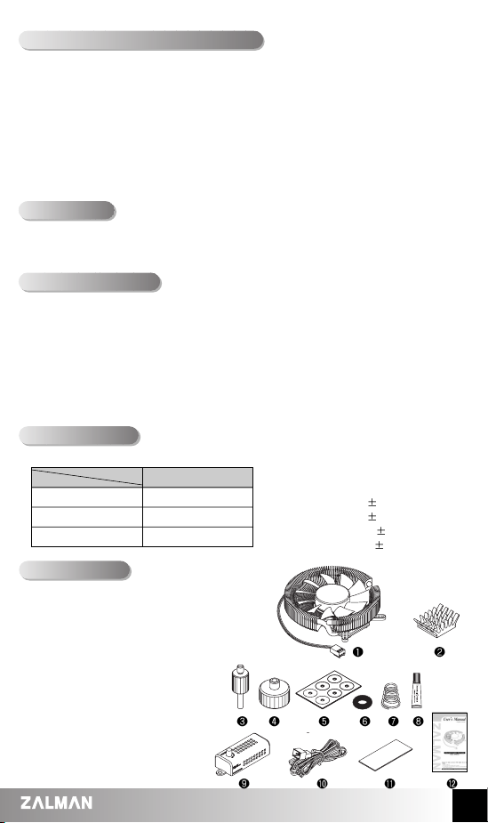
❶
One (1) VGA Cooler
❷
Eight (8) RAM Heatsinks
❸
Four (4) Nipples
❹
Four (4) Fixing Nuts
❺
One (1) PVC Washer Plate
❻
Four (4) Rubber Rings
❼
Four (4) Springs
❽
Thermal Grease
❾
FAN Controller(FAN MATE 2)
❿
Cable for FAN MATE 2
Dual-sided Tape
(to attach FAN MATE 2)
Manual
Components
***
MODEL
SPEC.
96 (L) X 96 (W) X 30 (H)
185
Pure copper
Dimensions (mm)
Weight (g)
Cooling Material
1. VGA Cooler
VF900-Cu
2. Fan
-
Size : 80(L) x 80(W) x 15(H)mm
- Bearing Type : 2-Ball Bearing
- Speed : 1,350rpm
10 % (Silent Mode)
2,400rpm
10 %
(Normal Mode)
- Noise level : 18.5dB
10 % (Silent Mode)
25.0dB
10 %
(Normal Mode)
Specifications
※
The specifications of any product may change without prior notice to improve performance.
2
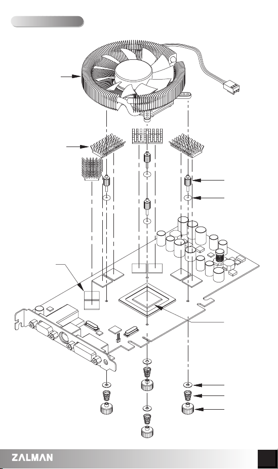
Exploded View
VGA Cooler
VGA RAM
RAM Heatsink
Nipple
Rubber Ring
VGA Chipset
PVC Washer
Spring
Fixing Nut

※
The specifications of any product may change without prior notice to improve performance.
3
Installation Procedure
Nipple Installation Holes for
Various VGA Cards
※※
The following installation sequence MUST be followed.
( VGA RAM Heatsink Attachment →→Thermal Grease Application →→Nipple Installation on the
Retention Guide →→VGA Cooler Installation →→Spring Insertion on the Fixing Nut →→Fixing Nut
Assembly on VGA Cooler’s Nipple →→VGA Card Installation →→Fan Power Cable Connection)
1. VGA RAM Heatsink Attachment
Remove the film from the thermal tapes on the bottom of the
RAM Heatsinks and attach the heatsinks on the VGA RAM.
2. Thermal Grease Application
Clean the contact surface of the VGA Chipset
completely. Apply Thermal Grease on the VGA
Chipset that makes contact with the base of the
VGA Cooler.
3. Nipple Installation on the Retention Guide
Install the short end of the Nipples on the VGA
Cooler's Retention Guide after determining the
appropriate Nipple Installation Holes.
Note 1)
If Thermal Grease or other residue remains on the
RAM, the Thermal Tapes will not stick. Clean the
surface of the RAM with acetone or alcohol before
attaching.
Note 2)
The bonding strength of the Thermal Tapes reaches
90% after 24 hours of curing. Do not exert excessive
force on the RAM Heatsinks during this period.
Note 3)
Thermal Tapes are not reusable because they lose
adhesiveness after their initial attachment. Purchase
new Thermal Tapes if you need to reattach the RAM
Heatsinks.
(Note)
The Nipples MUST be tightened by hand. Using tools
to tighten the Nipples may damage the tips of the Nipples.
※※
Please check the table below to identify the correct
Nipple Installation Holes for specific models of
VGA cards.
VGA RAM
RAM Heatsink
Thermal
Tape
Film
Thermal
Grease
VGA Chipset
Nipple
Retention
Guide
VGA Cooler
Retention Guide
Nipple
Installation
Holes
Nipple Installation Holes
VGA Card
ATI X1600 Series
ATI X1300 Series
ATI Radeon 9 Series
(except 9550/9600)
ATI Radeon X Series
NVIDIA Geforce4 MX Series
NVIDIA Geforce FX 5200
NVIDIA Geforce FX 5500
NVIDIA Geforce FX 5600(FX 5700)
NVIDIA Geforce 6600 Series
(except 6600 AGP Series)
NVIDIA Geforce4 TI 4 Series
NVIDIA Geforce FX 5700(Ultra) Series
NVIDIA Geforce FX 5800 Series
NVIDIA Geforce 6600 Series
(except 6600 AGP Series)
ATI X1600 Series
NVIDIA Geforce 6600 Series
(except 6600 AGP Series)
NVIDIA Geforce FX 5900 Series
NVIDIA Geforce FX 5950 Series
ATI X1900 Series
ATI X1800 Series
NVIDIA Geforce 7900 Series
NVIDIA Geforce 7800 Series
NVIDIA Geforce 6800 Series
❶
❷
❸
❹
❺
***
**

※
The specifications of any product may change without prior notice to improve performance.
4
4. VGA Cooler Installation
① Insert the Rubber Rings into the VGA cooler’s Nipple.
② Install the Nipple-attached VGA cooler on the VGA card’s Mounting Holes.
※ The VGA Chipset MUST be positioned on the center of the VGA Cooler’s base.
③ Simultaneously hold the VGA Cooler and the VGA card with one hand, then flip the VGA card
so that its rear-side is facing upwards.
(Note)
Make sure that the VGA Chipset and the VGA Cooler’s base do not get disconnected while simultaneously
flipping the VGA Cooler and the VGA card.
5. Spring Insertion on the Fixing Nut
Slowly turn the Spring in countclockwise motion so
that the Spring is correctly attached to the Fixing Nut.
Note 1)
The ends of the Springs are of different diameters. Install
the Spring end with the shorter diameter on the Fixing Nut.
Note 2)
Make sure that the Spring is installed perpendicularly and
not leaning to one side.
VGA Cooler
Nipple
Rubber Ring
Nipple
Rubber Ring
Mounting Hole
VGA Chipset
Nipple
VGA Cooler
Spring
Fixing
Nut

※
The specifications of any product may change without prior notice to improve performance.
5
6. Fixing Nut Installation on the Nipples
① Place a PVC Washer over each Nipple.
② Slightly screw each of the four Spring-attached-Fixing Nuts onto each Nipple, then tighten
each Fixing Nut one rotation at a time until all are completely tightened.
8. Fan Power Cable Connection (FAN MATE 2 connection)
7. VGA Card Installation
I
nsert the assembled VGA card into the motherboard’s
PCIe (or AGP) slot. Use the
Fixing Bolt to secure the
VGA card onto the
computer case. If the VGA card
has a power connector on
it, remember to plug in the
power cable.
Note 1)
Fully tightening one Fixing Nut at a time may result
in damaging the VGA chipset. Please tighten each
Fixing Nut one rotation at a time until all are
completely tightened.
Note 2)
Make sure that the VGA Cooler’s base and the
VGA Chipset are completely in contact with each
other.
Note 3)
Make sure that the VGA Cooler does not interfere
with the VGA card's capacitors and other components.
PCIe
Slot
Fixing
Bolt
Nipple
Fixing Nut
PVC Washer
VGA Cooler
①①
Installing FAN MATE 2 on the Inside of the System ②②Installing FAN MATE 2 on the Outside of the System
Connect the appropriate 3-pin connector on the
cable to the motherboard fan header and the
VF900-Cu fan connector.
Pull the 6-pin connector out of the system
through the back and connect it to FAN MATE 2,
which should be installed on the case using the
included double-sided tape (⑪).
◆ When the RPM control knob on FAN MATE 2 is turned fully counter-clockwise, the fan operates in
Silent Mode. Turned fully clockwise, it operates in Normal Mode. You can select the desired fan RPM
by turning the knob.
※※
Performance can be increased by adjusting the RPM control knob of the FAN MATE 2.
Note) FAN MATE 2 has been specifically designed for the fan of this product.
Zalman Tech Co., Ltd. is not responsible for any damage to systems or VGA Chipsets caused by
using it with other types of fans.
RPM Control Knob
Fan Connector
(VF900-Cu)
Motherboard
Double - sided Tape
FAN MATE 2
6-Pin Connector

※
The specifications of any product may change without prior notice to improve performance.
6
When building a noiseless computer, use Zalman’s Ultra Quiet CPU Cooler, Noiseless Power
Supply, Heatpipe HDD Cooler, Fanless Northbridge Cooler and Noiseless Case Fan for more stable
performance and a noiseless environment.
Zalman Computer Noise Prevention Systems
Home Theater PC Enclosures
TNN Computer Enclosures are the world’s first environment-friendly noiseless computer enclosures
that operate without the use of a fan. TNN Computer Enclosures use the aluminum enclosure itself
as a heatsink. They are ideal for environments that require silence, as well as for home theatre
systems and multi-media systems.
The HD160 is designed for ultra quiet home theatre
PC operation, utilizing optimized ventilation and
anti-vibration reinforcements, making it ideal for
environments that require silence such as living
rooms, bedrooms, educational facilities, and offices.
For more information, please visit our website.
TNN (Totally No Noise) Computer Enclosures
Noiseless Power Supply Heatpipe HDD Cooler
Ultra Quiet CPU Cooler
Fanless Northbridge Cooler Noiseless Case FAN
TNN 300 TNN 500 AF
HD 160
 Loading...