

Page 1

RESERATOR 2
English Version
Visit our website (www.zalman.co.kr) and watch the Reserator 2 installation
video for an installation overview.
※ Please read this manual thoroughly before installation.
※ The specifications of this product and its components may change without prior notice to improve the performance thereof.
www.zalman.co.kr www.zalmanusa.com
Page 2

RESERATOR 2
2
※
The specifications of any product may change without prior notice to improve performance.
1. Make sure that the power source’s output voltage and frequency are compatible with
the power input requirements of the water pump before installing (input voltage and
frequency of the water pump are shown on the box).
2. Do not place in dusty or humid conditions, under direct sunlight, or near a heat source
such as a room heater.
3. Do not drop or subject it to excessive force.
4. CPU socket compatibility must be checked.
5. Familiarize yourself with this manual.
6. Do not mix any contaminant with the coolant when filling, for it may cause product failure.
7. Check for leaks on Water Blocks before installation.
Installation Notes
1. Reserator 2 simultaneously operates with the PC. The power must first be supplied to
the AC power cable before turning on the PC because it uses an AC pump.
2. Place the Reserator 2 and the PC body at the same location for use.
3. If the coolant isn’t circulating properly, or if the pump flux becomes too low, then the
red blinkers will flash as well as warning sound. In this case, turn the PC OFF immediately.
4. Do not place any objects on the product.
5. Install on a flat surface with no vibration or slant, and do not tilt or lay horizontally.
6. Use distilled water with the coolant, regularly check the amount of coolant, and replenish
as needed (must be replenished every year).
7. If a leak is found, turn off the system immediately, and contact the place of purchase
or ZALMAN.
8. If the system will not be used for an extended period of time, then turn the Water
Pump OFF.
9. When moving the system, separate the Reserator from the PC case before moving.
10. Do not let any air bubbles form inside the Water Block and the tubes during operation.
11. Always make sure that the Water Pump is functioning properly.
12. If the power supply cord is damaged, it must be replaced by the manufacturer, its
service agent, or a similarly qualified person in order to avoid a hazard.
Operational Notes
Installation and Operational Notes
Page 3

3
English
RESERATOR 2
※
The specifications of any product may change without prior notice to improve performance.
Reserator 2 incorporates Zalman’s HCET(High Capacity Extrusion Technique)
technology, high efficiency cooling technology, and optimal heat dissipation design for
exceptional cooling performance even through natural convection cooling.
The Reserator 2 is a noiseless and fanless water cooling system that incorporates a and
Flow Indicator in the front section, a high efficiency heatsink in the middle section, and a
water tank and water pump in the back section which allows easy installation and use.
The anodized product and the provided coolant prevents corrosion. The new CPU
Water Block (ZM-WB4 Gold), VGA Water Block (ZM-GWB3), and the optional
Northbridge Water Block (ZM-NWB1) and VGA RAM Water Block (ZM-RWB1) enable
the setup of a complete Water Cooling System.
Installation and Operational Notes
1. Features
3
2. Specifications
5
3. Installation Overview
6
4. Standard Components and Optional Components
7
5. Installation Guide
9
6. External Water Pump Installation
15
7. Exploded View
16
8. Zalman Noise Prevention System
17
Table of Contents
1. Features
Page 4
RESERATOR 2
4
※
The specifications of any product may change without prior notice to improve performance.
1. 1 Reserator (Reservoir + Radiator + Water Pump)
“Reserator” is a compound word derived from ‘Reservoir’ and
‘Radiator’- it acts as a reservoir while radiating heat. This product
works well with natural convection and integrates a Water Pump
inside for convenience. It incorporates a flux observation/warning
device as well as the Flow Indicator in the front, which further allows
a safe and convenient use of the product.
1. 2 CPU Water Block (ZM-WB4 Gold)
The CPU Water Block incorporates a pure copper base for excellent
heat transfer, and is gold plating to prevent corrosion. It supports
Pentium 4 Socket 775/478 CPU and AMD Socket 754/939/940 CPU,
and is designed to be light weight and easy to install.
1. 3 VGA Water Block (ZM-GWB3)
The VGA Water Block incorporates a light weight pure aluminum base
for high cooling performance, and is anodized and coated to prevent
corrosion. It also incorporates revolving fittings that provide freedom in
direction when connecting them with the tubes, which further allows
simple installation.
1. 4 Northbridge Water Block (ZM-NWB1, Optional)
This anodized, pure aluminum block is built for high performance cooling, and is
designed for compatibility with a wide variety of Northbridge chipsets.
1. 5 VGA RAM Water Block (ZM-RWB1, Optional)
This anodized, pure aluminum RAM Water Block is built for high
performance cooling, and is compatible with GeForce 7800/7900 and ATI
X1800/X1900 in need of VGA RAM cooling. It provides easy installation.
1. 6 Anti-Corrosion Coolant (ZM-G300)
This coolant contains a high quality anti-corrosion agent for various
materials including copper, aluminum, plastic, that prevents corrosion for
long term operation.
1. 7 Flow Indicator
This component is connected with the circulation tube for checking the
circulation of the coolant. When the coolant is actively circulating, its
impeller rotates and the blue LED is brightly lit, providing easy indication
of the circulation status.
1. 8 Quick Coupling
The Fittings incorporate valves that prevent leaks when disconnecting
the PVC Tubes allowing quick, convenient separation and reassembly of
the Reserator for transport and coolant replacement.
Page 5

5
English
RESERATOR 2
※
The specifications of any product may change without prior notice to improve performance.
2. 1 Reserator (Reservoir + Radiator+Water pump)
1) Dissipation Area : 1.5㎡
2) Weight : 7 kg
3) Dimensions : 76(L) x 436(W) x 369(H) mm
4) Material : Anodized Pure Aluminum
5) Max Coolant Capacity : 1.25ℓ
6) Integrated Water Pump : 5 W, Qmax 300 ℓ/h
(A type : 230V-50Hz, B type : 115V-60Hz, C type : 220V-60Hz, D type : 100V-60Hz)
7) Maximum Lift : 0.5 m
2. 2 CPU Water Block (ZM-WB4 Gold)
1) Weight : 135 g
2) Material : Polycarbonate Cover, Gold Plated Pure Copper Base
3) Dimensions : 63(L) x 63(W) x 16.5(H) mm
4) Compatibility : Intel Pentium 4 (Socket 775/478), AMD Sempron / AMD64 (Athlon
64/Athlon 64 FX/Opteron) (Socket 754/939/940)
2. 3 VGA Water Block (ZM-GWB3)
1) Weight : 100 g
2) Material : Anodized Pure Aluminum
3) Dimensions : 60.4(L) x 60.4(W) x 30(H) mm
4) Compatibility : Graphics cards with heatsink mounting holes
2. 4 Northbridge Water Block (ZM-NWB1, Optional)
1) Weight : 48 g
2) Material : Anodized Pure Aluminum
3) Dimensions : 43(L) x 43(W) x 30(H) mm
2. 5 VGA RAM Water Block (ZM-RWB1, Optional)
1) Weight : 120 g
2) Material : Anodized Pure Aluminum
3) Dimensions : 19(L) x 122(W) x 12(H) mm
2. 6 Anti-Corrosion Coolant(ZM-G300)
1) Material : Propylene Glycol & Anti-Corrosion Agent
2) Volume : 250
mℓ
3) Freezing Point : -9 ℃
4) Exchange Cycle : 1 year
2. Specifications
Page 6

RESERATOR 2
6
※
The specifications of any product may change without prior notice to improve performance.
3. Installation Overview
DC Cable
Power Supply
4-Pin Connecter
CPU
Water
Block
VGA
Water
Block
I/O Bracket
Quick Coupling
AC Cable
Page 7

7
English
RESERATOR 2
※
The specifications of any product may change without prior notice to improve performance.
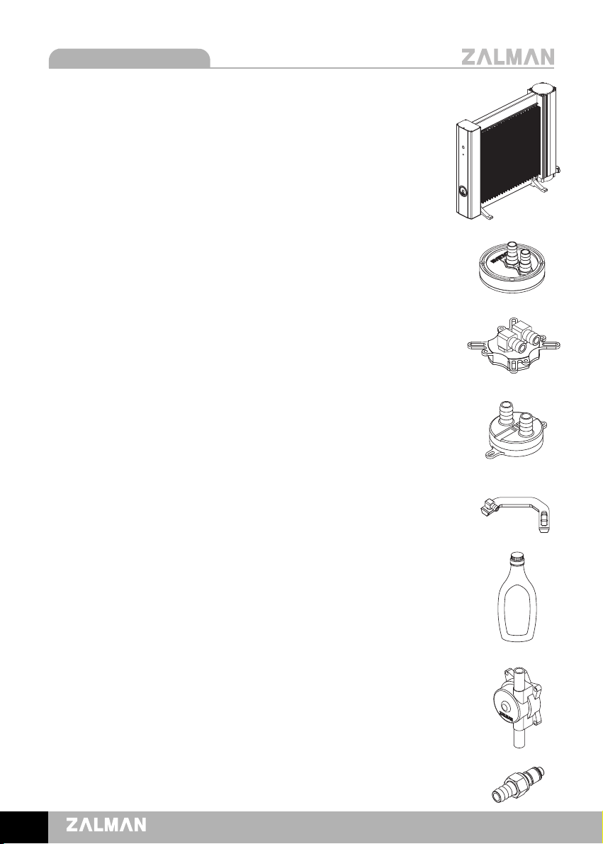
4. Components
4. 1 Reserator 2 - 1 UNIT
4. 2
CPU Water Block (ZM-WB4 Gold) 1SET
Please refer to the separately provided
manual for the ZM-WB4 Gold.
4.
3 VGA Water Block (ZM-GWB3) 1SET
Please refer to the separately provided
manual for the ZM-GWB3.
4. 6 Coolant (ZM-G300) 1EA
4. 7 PVC Tube 4m
4. 8 I/O Bracket 1EA
4. 9
Degassing Tube 1EA
4. 10 Tube Clamp 2EA
4. 11 Bolt- 4EA
4. 4 Support- 2EA
4. 5 Jump Cable 1EA
4. 12 User’s Manual
Page 8

RESERATOR 2
8
※
The specifications of any product may change without prior notice to improve performance.
Optional Components
●●
Power Supply
By implementing heat-sensor circuitry that controls the
fan’s speed in relation to the temperature within the
power supply, noise is significantly reduced, making this
component suitable for noiseless systems.
●●
Northbridge Water Block (ZM-NWB1)
This anodized, pure aluminum block is built for high
performance cooling, and is designed for Motherboard
compatibility with a wide variety of northbridge chipsets.
●●
VGA RAM Water Block (ZM-RWB1)
This VGA RAM Water Block is compatible with GeForce
7800/7900 and ATI X1800/X1900 in need of VGA RAM
cooling.
●●
Heatpipe HDD Cooler
This component cools the heat generated from the hard
disk drive and reduces the vibration that is passed onto
the computer’s enclosure.
●●
PVC Tube
If the standard PVC tube is found to be short or you need
to use the tube on another system, additional tubes can
be purchased separately (12 x 8 mm).
Page 9

9
English
RESERATOR 2
※
The specifications of any product may change without prior notice to improve performance.
5. Installation Guide
5. 1 Determine the Placement of the
Reserator
The Reserator’s placement should be determined
in relation to the position of the PC.
Place it upright next to or slightly above the PC.
Note that if the Reserator is placed lower than
the PC, the PVC tube’s internal air pressure
may prevent proper initial operation.
5. 2 Install the Supports
Install the enclosed Supports on to the Tab
located on the bottom of the Reserator with
the use of Bolts.
5. 3 Fill the Coolant
1) Take off the Reserator Cover after unscrewing
its Bolts.
2) Fill with the provided coolant (ZM-G300,
250㎖) and one liter of distilled water.
Note 1) Fill in approximately 50% to avoid
overflow within the Reservoir, and
must refill because the water level
decreases once the coolant begins to
circulate after perfectly releasing the
air within the Reservoir.
Note 2) The provided coolant is a concentrate,
and must be mixed down with distilled
water in the ratio of 1:4.
Note 3) Read the warning label on the coolant
before use.
Note 4) Keep this product and its associated
system away from children.
((OO)) ((OO))
((XX)) ((XX))
Bolt
Reservoir Cover
Reservoir
Distilled Water
G300
Page 10

RESERATOR 2
10
※
The specifications of any product may change without prior notice to improve performance.
5. 4 Reserator’s Coolant Circulation
1) The purpose of connecting the Jump Cable of the power supply’s main connector
(20P/24P) is to receive direct current (12V) needed for the test and leakage inspection.
2) Turn off all power of the PC and switch the Power Supply's ON/OFF button to OFF, connect
the enclosed Degassing Tube to the Reserator’s IN-OUT, and provide power to the AC cable.
3) Disconnect the power supply's main connector (20P/24P) and the CPU 4-Pin connector
from the motherboard, and connect the green wire terminal with the black wire terminal
with the use of Jump Cable.
4) Connect the Reserator’s DC cable connector to the power supply’s 4-Pin connector,
and provide power to the PC by switching the power supply's ON/OFF button to ON.
5) Blue LED will light up and the impeller located inside the Flow Indicator of the Reserator’s
front panel will begin to rotate when the power is supplied. (At this moment, let the
coolant circulate for approximately 30 seconds, then cut off the direct current and
wait for the impeller to stop. Once the impeller has come to a complete halt, you
must restart it in order to entirely eliminate the internal air. )
6) If the coolant is not circulating well due to internal air pressure during initial operation,
then tilt the Reserator by approximately 70。and repeatedly turn the Reserator ON/OFF
with the Light/Reset button to completely release internal air trapped within the Reserator
body (must press the Reset button for longer than 5 seconds).
7) If the coolant is circulating properly, then turn of the power of the Power Supply, disconnect
the Degassing Tube, and disassemble the Quick Coupling Insert.
Note 1) Pay attention so that the coolant inside the Reservoir does not spill.
Note 2) Check the state of air release with the tube. If air is completely released, then turn
off the Power Supply and begin installing the water blocks.
Note 3) During coolant circulation, if the Flow Indicator fails to effectively sense the flux,
then the alarm will go off and the red LED will flicker. Press onto the Light/Reset
button for 5 seconds to reboot.
Quick Coupling
Insert
Degassing Tube
4-Pin Connecter
DC Cable Connecter
Main
Connecter
Motherboard
Power Connecter
Black Wire
Green Wire
Jump Cable
Light/Reset Button
Page 11

11
English
RESERATOR 2
※
The specifications of any product may change without prior notice to improve performance.
5. 6 Install the VGA Water Block (ZM-GWB3)
1) Refer to the manual included with the ZM-GWB3 for installation instructions.
2) If physical interference occurs while installing the Water Block, then stop the installation.
5. 5 Install the CPU Water Block (ZM-WB4 Gold)
1) Refer to the manual included with the ZM-WB4 Gold for installation instructions.
2) If physical interference occurs while installing the Water Block, then stop the installation.
5. 7 Connect the CPU Water Block and
the VGA Water Block
Connect the two Water Blocks with the PVC
Tube as shown in the diagram. Must install
the Tube Clamp
5. 8 Connect the VGA Water Blcok with
Reserator’s Base IN
1) Connect one end of the PVC Tube to the VGA Water Block Fitting and fasten with a
Tube Clamp as shown in the diagram. .
2) Pull out the PVC Tube through the I/O Bracket hole on the computer case.
3) Connect the Quick Coupling Insert that has been disconnected from the Degassing
Tube to the other end of the PVC tube, and fasten it with the use of Tube Clamp.
4) Plug the Quick Coupling Insert into the Reserator’s Base IN fitting.
PVC Tube
CPU Water
Block
VGA Water
Block
5. 9 Connect the CPU Water Block with the Base Out
1) Connect one end of the PVC Tube to the CPU Water Block Fitting and fasten with
Tube Clamp as shown in the diagram.
2) Pull out the PVC Tube through the tube hole of the I/O Bracket.
3) Connect the Quick Coupling Insert to the other end of the PVC Tube, and fasten with
Tube Clamp.
I/O Bracket
Base IN Quick Coupling Body
Quick Coupling Insert
Page 12

RESERATOR 2
12
※
The specifications of any product may change without prior notice to improve performance.
5. 10 Connect DC Power Cable
1) Fit the DC Cable’s Cord Bushing into the groove of the I/O Bracket, and fasten the I/O
Bracket with the use of Bolts.
2) Connect the DC Cable connector to the 4-Pin connector of the Power Supply.
Note 1) Do not exert excessive force when connecting the connector.
Slowly connect with two hands.
5. 11 Installing the Northbridge Water Block
1) To install the Northbridge Water Block, connect as shown in the diagram below.
2) Remember to install Tube Clamps on the PVC Tubes during installation.
CPU Water Block
Tube Clamp
Northbridge Water Block
VGA Water Block
I/O Bracket
Cord Bushing
Bolt
4-Pin
Connecter
DC Cable Connecter
4) Plug the Quick Coupling Insert into the Base OUT located on the lower part of the Reserator
Base OUT, Quick Coupling Body
Page 13

13
English
RESERATOR 2
※
The specifications of any product may change without prior notice to improve performance.
5. 13 Confirm Proper Installation
1) Check that the product is placed properly.
2) Confirm that the coolant circulation path is correct as shown below.
3) Lightly tug the PVC tube connected to each of the fittings to check for loose ends.
5. 14 Leakage Inspecting and Test Run
1) Supply power to the Reserator’s AC cable, and check to see if the green wire terminal
and the black wire terminal of the power supply’s main connector are connected to each
other with Jump Cable.
2) Check the amount of coolant inside the Reserator’s Reservoir, and fill it by approximately 70%.
3) Connect the power supply’s 4-Pin connector to the Reserator’s DC cable connector,
and provide power for the Power Supply by switching its ON/OFF button to ON.
4) Once the power is supplied, check to see if the flow indicator's impeller placed inside the
Reserator’s front panel is rotating, if the Blue LED is lit, and if the coolant is being circulated
to each water block.
Reserator OUT
CPU Water Block
N/B Water Block
VGA Water Block
RAM Water Block
Reserator IN
Flow Indicator
Heat Sink
Radiate
Heat
Absorb
Heat
Water Pump
CPU Water Block
VGA Water Block
VGA RAM Water Block
5. 12 Installing the VGA RAM Water Block
1) To install the VGA RAM Water Block, connect as shown in the diagram below.
2) Remember to install Tube Clamps on the PVC Tubes during installation.
Page 14

RESERATOR 2
14
※
The specifications of any product may change without prior notice to improve performance.
5) Check for leakage at each connector. Leakage can lead to short-circuit and damage of
the motherboard and other components.
6) If leakage occurs, immediately stop the pump, clean the leakage area with tissue paper,
and reassemble the leakage area.
7) If there is no leakage, remove the power Jump Cable of the power supply’s main connector.
Now connect the power supply’s main connector to the motherboard’s power connector,
and operate the PC. (connect the disassembled CPU 4-Pin connector as it originally was.)
Note 1) Power must always be supplied to the Reserator’s AC cable in order for the Reserator
and the PC to be run at the same time. Must check to see if the power is constantly
being supplied to the AC cable.
Note 2) Using the Reserator AC power and the PC power on the same multi-tab is recommended.
Note 3) After the test run is complete and everything is functioning properly, must check to
see if the Reserator’s DC cable is connected to the power supply’s 4-Pin connector.
5. 16 Front Panel Controller Functions
1) Flux Check
Warning sound will go off and the red LED will flicker when the flux falls below a certain
level due to a problem in pump, leakage, or other problems. Detection of these problems
allows prevention of damage.
2) Simultaneous Operation with PC
By supplying power to the AC Cable, and by connecting the DC Cable to the 4-Pin Connector
of the Power Supply, it can operate in accordance with the PC power’s ON/OFF, which
allows ease and simplicity in use.
3) Light ON/OFF
The Blue LED will turn on if the Light/Reset button is shortly pressed, and the Blue LED
will turn off if the Light/Reset button is pressed again. This allows the users to be able to
quickly check whether the product is in use or not.
4) Flow Indicator
The coolant flow can be observed with naked eyes by seeing the Flow Indicator with its
integrated impeller, and bright Blue LED produces an elegant feel.
5. 15 How to Use the Front Panel Controller
1. Supply power to AC cable, and connect DC cable with 4-Pin connector
2. Supply Power to PC Warninig Sound, RED LED Turn off
3. PUMP Operates and Blue LED
Lights up
Press onto the Right/Reset Button
for More than five seconds
If Problem is
encountered
If no Problem
is encountered
Page 15

15
English
RESERATOR 2
※
The specifications of any product may change without prior notice to improve performance.
6. External Pump Installation
6. 1 Installing the External Water Pump
After determining the placement of the External Water Pump, check the components that
create a path as shown above. If is recommended that the installation is done in such a manner.
6. 2 Cautionary Notes on Choosing and Installing an External Water Pump
1) When installing an External Water Pump, confirm the coolant entrance and exit holes
before connection.
2) Check that the chosen Water Pump°Øs holes are compatible with the provided PVC
tubes (12 x 8 mm).
3) Zalman Tech is not responsible for performance degradation or malfunction of a system
that results from using an external Water Pump.
CPU
Water
Block
VGA Water
Block
External Water Pump
Page 16

RESERATOR 2
16
※
The specifications of any product may change without prior notice to improve performance.
7. Exploded View
Reservoir Cover
Heat Sink
Front Body
Flow Indicator
Water Pump
Quick Coupler Body
Reservoir Base
Support
Light/Reset
Button
Front Panel
Page 17

17
English
RESERATOR 2
※
The specifications of any product may change without prior notice to improve performance.
8. Zalman Noise Prevention System
Stable performance and noiseless liquid cooling system can both be achieved with the use
of Zalman’s Noiseless Power Supply, Hard Disk Cooler and Noiseless Case Fan,
Northbridge Water Block.
TNN(Totally No Noise) Computer Case
TNN Computer Enclosures are the world’s first environment-friendly noiseless computer
enclosures that operate without the use of a fan. TNN Computer Enclosures use the
aluminum enclosure itself as a heatsink. They are ideal for environments that require
silence, as well as for home theatre systems and multi-media systems.
Noiseless Power Supply Heatpipe HDD Cooler Noiseless Case Fan Northbridge Water Block
TNN 300 TNN 500AF
Home Theater PC Enclosures
The HD160 is designed for ultra quiet home theatre
PC operation, utilizing optimized ventilation and
anti-vibration reinforcements, making it ideal for
environments that require silence such as living
rooms, bedrooms, educational facilities, and offices.
For more information, please visit our website.
HD160
Page 18

 Loading...