

York DJ150 User Manual
INSTALLATION
MANUAL
®
MAGNUM
CONTENTS
GENERAL . . . . . . . . . . . . . . . . . . . . . . . . . . . . . . . . .4
SAFETY CONSIDERATIONS. . . . . . . . . . . . . . . . . .4
INSPECTION. . . . . . . . . . . . . . . . . . . . . . . . . . . . . . .4
REFERENCE. . . . . . . . . . . . . . . . . . . . . . . . . . . . . . .5
RENEWAL PARTS . . . . . . . . . . . . . . . . . . . . . . . . . .5
APPROVALS. . . . . . . . . . . . . . . . . . . . . . . . . . . . . . .5
NOMENCLATURE . . . . . . . . . . . . . . . . . . . . . . . . . .6
INSTALLATION. . . . . . . . . . . . . . . . . . . . . . . . . . . . .8
OPERATION . . . . . . . . . . . . . . . . . . . . . . . . . . . . . .33
START-UP (COOLING). . . . . . . . . . . . . . . . . . . . . .39
START-UP (GAS HEAT) . . . . . . . . . . . . . . . . . . . . .39
TROUBLESHOOTING . . . . . . . . . . . . . . . . . . . . . .43
See following pages for a complete Table of Contents.
SINGLE PACKAGE AIR CONDITIONERS AND
SINGLE PACKAGE GAS/ELECTRIC UNITS
DJ150
12-1/2 TON
(10.8 EER)
NOTES, CAUTIONS AND WARNINGS
The installer should pay particular attention to the words:
NOTE, CAUTION, and WARNING. Notes
clarify or make the installation easier. Cautions
to prevent equipment damage. Warnings
installer that personal injury and/or equipment damage
may result if inst allation procedure is no t handled properly.
CAUTION: READ ALL SAFETY GUIDES BEFORE YOU
BEGIN TO INSTALL YOUR UNIT.
SA VE THIS MANUAL
are intended to
are given
are given to alert
T ested in accordance with:
035-19046-002-B-0104

TABLE OF CONTENTS
035-19046-002-B-0104
GENERAL . . . . . . . . . . . . . . . . . . . . . . . . . . . . . . . . . . . . . .4
SAFETY CONSIDERATIONS . . . . . . . . . . . . . . . . . . . . . . . 4
INSPECTION . . . . . . . . . . . . . . . . . . . . . . . . . . . . . . . . . . . . 4
REFERENCE . . . . . . . . . . . . . . . . . . . . . . . . . . . . . . . . . . . .5
RENEWAL PARTS. . . . . . . . . . . . . . . . . . . . . . . . . . . . . . . . 5
APPROVALS . . . . . . . . . . . . . . . . . . . . . . . . . . . . . . . . . . . . 5
NOMENCLATURE . . . . . . . . . . . . . . . . . . . . . . . . . . . . . . . . 6
INSTALLATION . . . . . . . . . . . . . . . . . . . . . . . . . . . . . . . . . . 8
INSTALLATION SAFETY INFORMATION . . . . . . . . . . . . . . . 8
PRECEDING INSTALLATION . . . . . . . . . . . . . . . . . . . . . . . . 8
LIMITATIONS . . . . . . . . . . . . . . . . . . . . . . . . . . . . . . . . . . . . . 9
LOCATION . . . . . . . . . . . . . . . . . . . . . . . . . . . . . . . . . . . . . . 11
RIGGING AND HANDLING . . . . . . . . . . . . . . . . . . . . . . . . . 11
CLEARANCES . . . . . . . . . . . . . . . . . . . . . . . . . . . . . . . . . . . 12
DUCTWORK. . . . . . . . . . . . . . . . . . . . . . . . . . . . . . . . . . . . . 15
DUCT COVERS . . . . . . . . . . . . . . . . . . . . . . . . . . . . . . . . . . 15
CONDENSATE DRAIN. . . . . . . . . . . . . . . . . . . . . . . . . . . . . 17
COMPRESSORS . . . . . . . . . . . . . . . . . . . . . . . . . . . . . . . . . 17
FILTERS . . . . . . . . . . . . . . . . . . . . . . . . . . . . . . . . . . . . . . . . 17
THERMOSTAT WIRING. . . . . . . . . . . . . . . . . . . . . . . . . . . . 17
POWER AND CONTROL WIRING. . . . . . . . . . . . . . . . . . . . 17
POWER WIRING DETAIL. . . . . . . . . . . . . . . . . . . . . . . . . . . 18
OPTIONAL ELECTRIC HEAT. . . . . . . . . . . . . . . . . . . . . . . . 22
OPTIONAL GAS HEAT. . . . . . . . . . . . . . . . . . . . . . . . . . . . . 23
GAS PIPING. . . . . . . . . . . . . . . . . . . . . . . . . . . . . . . . . . . . . . .23
GAS CONNECTION. . . . . . . . . . . . . . . . . . . . . . . . . . . . . . . . .24
LP UNITS, TANKS AND PIPING . . . . . . . . . . . . . . . . . . . . . . .24
VENT AND COMBUSTION AIR . . . . . . . . . . . . . . . . . . . . . . . .25
FACTORY INSTALLED OPTIONS/
FIELD INSTALLED ACCESSORIES . . . . . . . . . . . . . . . . . . 25
ELECTRIC HEAT. . . . . . . . . . . . . . . . . . . . . . . . . . . . . . . . . . . 25
MOTORIZED OUTDOOR DAMPER . . . . . . . . . . . . . . . . . . . .25
ECONOMIZER . . . . . . . . . . . . . . . . . . . . . . . . . . . . . . . . . . . . .25
POWER EXHAUST . . . . . . . . . . . . . . . . . . . . . . . . . . . . . . . . .25
RAIN HOOD. . . . . . . . . . . . . . . . . . . . . . . . . . . . . . . . . . . . . . .25
ECONOMIZER AND POWER EXHAUST SET POINT
ADJUSTMENTS AND INFORMATION. . . . . . . . . . . . . . . . . 26
MINIMUM POSITION ADJUSTMENT . . . . . . . . . . . . . . . . . . .26
ENTHALPY SET POINT ADJUSTMENT . . . . . . . . . . . . . . . . .26
POWER EXHAUST DAMPER SET POINT (WITH OR
WITHOUT POWER EXHAUST). . . . . . . . . . . . . . . . . . . . . . . .26
INDOOR AIR QUALITY AQ . . . . . . . . . . . . . . . . . . . . . . . . . . .26
PHASING . . . . . . . . . . . . . . . . . . . . . . . . . . . . . . . . . . . . . . . 28
BLOWER ROTATION. . . . . . . . . . . . . . . . . . . . . . . . . . . . . . 28
BELT TENSION . . . . . . . . . . . . . . . . . . . . . . . . . . . . . . . . . . 28
AIR BALANCE . . . . . . . . . . . . . . . . . . . . . . . . . . . . . . . . . . . 31
CHECKING AIR QUANTITY. . . . . . . . . . . . . . . . . . . . . . . . . 31
METHOD ONE. . . . . . . . . . . . . . . . . . . . . . . . . . . . . . . . . . . . .3 1
METHOD TWO. . . . . . . . . . . . . . . . . . . . . . . . . . . . . . . . . . . . .31
SUPPLY AIR DRIVE ADJUSTMENT . . . . . . . . . . . . . . . . . . 32
OPERATION. . . . . . . . . . . . . . . . . . . . . . . . . . . . . . . . . . . . 33
SEQUENCE OF OPERATIONS OVERVIEW. . . . . . . . . . . . 33
COOLING SEQUENCE OF OPERATION . . . . . . . . . . . . . . 33
CONTINUOUS BLOWER. . . . . . . . . . . . . . . . . . . . . . . . . . . . . 33
INTERMITTENT BLOWER. . . . . . . . . . . . . . . . . . . . . . . . . . . .33
NO OUTDOOR AIR OPTIONS. . . . . . . . . . . . . . . . . . . . . . . . .34
ECONOMIZER WITH SINGLE ENTHALPY SENSOR -. . . . . .34
ECONOMIZER WITH DUAL ENTHAL PY SENSORS - . . . . . .34
ECONOMIZER (SINGLE OR DUAL) WITH POWER
EXHAUST -. . . . . . . . . . . . . . . . . . . . . . . . . . . . . . . . . . . . . . . .34
MOTORIZED OUTDOOR AIR DAMPERS - . . . . . . . . . . . . . . .34
COOLING OPERATION ERRORS. . . . . . . . . . . . . . . . . . . . . .34
HIGH-PRESSURE LIMIT SWITCH. . . . . . . . . . . . . . . . . . . . . .34
LOW-PRESSURE LIMIT SWITCH . . . . . . . . . . . . . . . . . . . . . .35
FREEZESTAT. . . . . . . . . . . . . . . . . . . . . . . . . . . . . . . . . . . . . .35
LOW AMBIENT COOLING . . . . . . . . . . . . . . . . . . . . . . . . . . . .35
SAFETY CONTROLS. . . . . . . . . . . . . . . . . . . . . . . . . . . . . . 35
COMPRESSOR PROTECTION. . . . . . . . . . . . . . . . . . . . . . 35
FLASH CODES. . . . . . . . . . . . . . . . . . . . . . . . . . . . . . . . . . . . .35
RESET . . . . . . . . . . . . . . . . . . . . . . . . . . . . . . . . . . . . . . . . . . .36
ELECTRIC HEATING SEQUENCE OF OPERATIONS. . . . 36
ELECTRIC HEATING OPERATION ERRORS . . . . . . . . . . 36
TEMPERATURE LIMIT. . . . . . . . . . . . . . . . . . . . . . . . . . . . . . .36
SAFETY CONTROLS . . . . . . . . . . . . . . . . . . . . . . . . . . . . . . . .36
LIMIT SWITCH (LS) . . . . . . . . . . . . . . . . . . . . . . . . . . . . . . . . .36
FLASH CODES. . . . . . . . . . . . . . . . . . . . . . . . . . . . . . . . . . . . .36
RESET . . . . . . . . . . . . . . . . . . . . . . . . . . . . . . . . . . . . . . . . . . .36
ELECTRIC HEAT ANTICIPATOR SETPOINTS. . . . . . . . . . 36
GAS HEATING SEQUENCE OF OPERATIONS . . . . . . . . . 37
IGNITION CONTROL BOARD . . . . . . . . . . . . . . . . . . . . . . . 37
FIRST STAGE OF HEATING . . . . . . . . . . . . . . . . . . . . . . . . . .37
SECOND STAGE OF HEATING. . . . . . . . . . . . . . . . . . . . . . . .37
RETRY OPERATION . . . . . . . . . . . . . . . . . . . . . . . . . . . . . . . .37
RECYCLE OPERATION. . . . . . . . . . . . . . . . . . . . . . . . . . . . . .37
GAS HEATING OPERATION ERRORS. . . . . . . . . . . . . . . . 37
LOCK-OUT . . . . . . . . . . . . . . . . . . . . . . . . . . . . . . . . . . . . . . . .37
TEMPERATURE LIMIT. . . . . . . . . . . . . . . . . . . . . . . . . . . . . . .37
FLAME SENSE. . . . . . . . . . . . . . . . . . . . . . . . . . . . . . . . . . . . .37
GAS VALVE . . . . . . . . . . . . . . . . . . . . . . . . . . . . . . . . . . . . . . .37
SAFETY CONTROLS. . . . . . . . . . . . . . . . . . . . . . . . . . . . . . 38
LIMIT SWITCH (LS) . . . . . . . . . . . . . . . . . . . . . . . . . . . . . . . . .38
AUXILIARY LIMIT SWITCH (ALS) . . . . . . . . . . . . . . . . . . . . . .38
PRESSURE SWITCH (PS). . . . . . . . . . . . . . . . . . . . . . . . . . . .38
ROLLOUT SWITCH (ROS). . . . . . . . . . . . . . . . . . . . . . . . . . . .38
INTERNAL MICROPROCESSOR FAILURE . . . . . . . . . . . . . .38
FLASH CODES. . . . . . . . . . . . . . . . . . . . . . . . . . . . . . . . . . . . .38
RESETS . . . . . . . . . . . . . . . . . . . . . . . . . . . . . . . . . . . . . . . . . .38
GAS HEAT ANTICIPATOR SETPOINTS. . . . . . . . . . . . . . . 39
START-UP (COOLING). . . . . . . . . . . . . . . . . . . . . . . . . . . 39
PRESTART CHECK LIST . . . . . . . . . . . . . . . . . . . . . . . . . . 39
OPERATING INSTRUCTIONS. . . . . . . . . . . . . . . . . . . . . . . 39
POST START CHECK LIST. . . . . . . . . . . . . . . . . . . . . . . . . 39
START-UP (GAS HEAT) . . . . . . . . . . . . . . . . . . . . . . . . . . 39
PRE-START CHECK LIST. . . . . . . . . . . . . . . . . . . . . . . . . . 39
OPERATING INSTRUCTIONS. . . . . . . . . . . . . . . . . . . . . . . 39
LIGHTING THE MAIN BURNERS. . . . . . . . . . . . . . . . . . . . . . .39
POST START CHECKLIST . . . . . . . . . . . . . . . . . . . . . . . . . 40
SHUT DOWN . . . . . . . . . . . . . . . . . . . . . . . . . . . . . . . . . . . . 40
MANIFOLD GAS PRESSURE ADJUSTMENT. . . . . . . . . . . 4 0
CHECKING GAS INPUT . . . . . . . . . . . . . . . . . . . . . . . . . . . 40
NATURAL GAS. . . . . . . . . . . . . . . . . . . . . . . . . . . . . . . . . . . . .40
ADJUSTMENT OF TEMPERATURE RISE . . . . . . . . . . . . . 42
BURNERS/ORIFICES INSPECTION/SERVICING . . . . . . . 42
CHARGING THE UNIT . . . . . . . . . . . . . . . . . . . . . . . . . . . 43
TROUBLESHOOTING. . . . . . . . . . . . . . . . . . . . . . . . . . . . 43
PREDATOR“ MAGNUM FLASH CODES. . . . . . . . . . . . . . . 43
COOLING TROUBLESHOOTING GUIDE . . . . . . . . . . . . . . 46
GAS HEAT TROUBLESHOOTING GUIDE . . . . . . . . . . . . . 49
2 Unitary Products Group

035-19046-002-B-0104
LIST OF FIGURES
Fig. # Pg. #
1 UNIT SHIPPING BRACKET . . . . . . . . . . . . . . . . . . . . . 8
2 COMPRESSOR SECTION . . . . . . . . . . . . . . . . . . . . . . 9
3 PREDATOR“ MAGNUM COMPONENT LOCATION . 10
4 UNIT 4 POINT LOAD . . . . . . . . . . . . . . . . . . . . . . . . . 11
5 UNIT 6 POINT LOAD . . . . . . . . . . . . . . . . . . . . . . . . . 12
6 UNIT CENTER OF GRAVITY . . . . . . . . . . . . . . . . . . . 12
7 UNIT DIMENSIONS . . . . . . . . . . . . . . . . . . . . . . . . . . 13
8 BOTTOM DUCT OPENINGS (FROM ABOVE). . . . . . 14
9 REAR DUCT DIMENSIONS . . . . . . . . . . . . . . . . . . . . 15
10 PREDATOR“ MAGNUM ROOF CURB
DIMENSIONS . . . . . . . . . . . . . . . . . . . . . . . . . . . . . . . 16
11 SUNLINE™ TO PREDATOR“ MAGNUM
TRANSITION ROOF CURBS . . . . . . . . . . . . . . . . . . . 16
12 SIDE PANELS WITH HOLE PLUGS. . . . . . . . . . . . . . 16
13 RETURN DOWNFLOW PLENUM WITH PANEL . . . . 17
14 DISCHARGE PANEL IN PLACE. . . . . . . . . . . . . . . . . 17
15 CONDENSATE DRAIN. . . . . . . . . . . . . . . . . . . . . . . . 17
Fig. #
16 ELECTRONIC THERMOSTAT FIELD WIRING . . . . . 18
17 FIELD WIRING 24 VOLT THERMOSTAT . . . . . . . . . 19
18 FIELD WIRING DISCONNECT - COOLING UNIT
WITH/WITHOUT EL ECTRIC HEAT . . . . . . . . . . . . . . 19
19 FIELD WIRING DISCONNECT - COOLING UNIT
WITH GAS HEAT . . . . . . . . . . . . . . . . . . . . . . . . . . . . 20
20 SIDE ENTRY GAS PIPING. . . . . . . . . . . . . . . . . . . . . 23
21 BOTTOM ENTRY GAS PIPING . . . . . . . . . . . . . . . . . 23
22 ENTHALPY SET POINT CHART . . . . . . . . . . . . . . . . 27
23 HONEYWELL ECONOMIZER CONTROL W7212. . . 27
24 BELT ADJUSTMENT . . . . . . . . . . . . . . . . . . . . . . . . . 28
25 DRY COIL DELTA P. . . . . . . . . . . . . . . . . . . . . . . . . . 32
26 TYPICAL FLAME . . . . . . . . . . . . . . . . . . . . . . . . . . . . 39
27 TYPICAL GAS VALVE . . . . . . . . . . . . . . . . . . . . . . . . 42
28 BASIC TROUBLESHOOTING FLOWCHART . . . . . . 44
29 POWER ON FLOW CHART . . . . . . . . . . . . . . . . . . . . 44
30 TRIP FAILURE FLOW CHART. . . . . . . . . . . . . . . . . . 45
Pg. #
LIST OF TABLES
Tbl. # Pg. #
1 UNIT VOLTAGE LIMITATIONS. . . . . . . . . . . . . . . . . . 11
2 UNIT TEMPERATURE LIMITATIONS 11
3 UNIT WEIGHTS. . . . . . . . . . . . . . . . . . . . . . . . . . . . . . 1 2
4 4 POINT LOAD WEIGHT. . . . . . . . . . . . . . . . . . . . . . . 12
5 6 POINT LOAD WEIGHT. . . . . . . . . . . . . . . . . . . . . . . 12
6 UNIT CLEARANCES . . . . . . . . . . . . . . . . . . . . . . . . . . 13
7 CONTROL WIRE SIZES . . . . . . . . . . . . . . . . . . . . . . . 17
8 ELECTRICAL DATA DJ150 (12-1/2 TON) WITHOUT
POWERED CONVENIENCE OUTLET . . . . . . . . . . . . 21
9 ELECTRICAL DATA DJ150 (12-1/2 TON) WITH
POWERED CONVENIENCE OUTLET . . . . . . . . . . . . 21
10 PHYSICAL DATA. . . . . . . . . . . . . . . . . . . . . . . . . . . . . 22
11 MINIMUM SUPPLY AIR CFM . . . . . . . . . . . . . . . . . . . 22
12 GAS HEAT APPLICATION DATA . . . . . . . . . . . . . . . . 2 3
13 GAS PIPE SIZING - CAPACITY OF PIPE. . . . . . . . . . 23
14 SUPPLY AIR LIMITATIONS . . . . . . . . . . . . . . . . . . . . 28
15 DJ150, 12-1/2 TON STANDARD MOTOR DOWN
SHOT BLOWER PERFORMANCE . . . . . . . . . . . . . . . 29
Tbl. #
16 DJ150, 12-1/2 TON OPT IONAL MOT OR DOWN
SHOT BLOWER PERFORMANCE. . . . . . . . . . . . . . . 29
17 DJ150, 12-1/2 TON STANDARD MOTOR SIDE
SHOT BLOWER PERFORMANCE. . . . . . . . . . . . . . . 30
18 DJ150, 12-1/2 TON OPT IONAL MOT OR SIDE
SHOT BLOWER PERFORMANCE. . . . . . . . . . . . . . . 30
19 INDOOR BLOWER SPECIFICATIONS. . . . . . . . . . . . 31
20 ADDITIONAL STATIC RESISTANCE. . . . . . . . . . . . . 33
21 MOTOR SHEAVE DATUM DIAMETERS . . . . . . . . . . 33
22 ELECTRIC HEAT LIMIT SETTING . . . . . . . . . . . . . . . 36
23 ELECTRIC HEAT ANTICIPATOR SETPOINTS . . . . . 36
24 GAS HEAT LIMIT CONTROL SETTINGS. . . . . . . . . . 38
25 GAS HEAT ANTICIPATOR SETPOINTS . . . . . . . . . . 39
26 GAS HEAT STAGES. . . . . . . . . . . . . . . . . . . . . . . . . . 40
27 GAS RATE CUBIC FEET PER HOUR . . . . . . . . . . . . 41
28 UNIT CONTROL BOARD FLASH CODES . . . . . . . . . 43
29 IGNITION CONTROL FLASH CODES . . . . . . . . . . . . 43
Pg. #
Unitary Products Group 3

GENERAL
YORK Predator Magnum units are single package air conditioners with optional gas heating designed for outdoor
installation on a rooftop or slab and for non-residential use.
These units can be equipped with factory or field installed
electric heaters for heating applications.
035-19046-002-B-0104
If the information in this manual is not followed
exactly, a fire or explosion may result causing property damage, personal inj ury or loss of life.
These units are completely assembled on rigid, permanently
attached base rails. All piping, refrigerant charge, and electrical wiring is factory installed and tested. The units require
electric power, gas supply (where applicable), and duct connections. The electric heaters have nickel-chrome elements
and utilize single-point power connection.
SAFETY CONSIDERAT IONS
Should overheating occur, or the gas supply fail to
shut off, shut off the manual gas valve to the furnace
before shutting off the electrica l supply.
Do not use this furnace if any part has been under
water. Immediately c all a qualified service technician
to inspect the furnace and to replace any part of the
control system and any gas control which has been
under water.
Due to system pressure, moving parts, and electrical components, installation and servicing of air conditioning equipment
can be hazardous. Only qualified, trained service personnel
should install, repair, or service this equipment. Untrained
personnel can perform basic maintenance functions of cleaning coils and filters and replacing filters.
Do not store or use gasoline or other flammable
vapors and liquids in the vicinity of this or any other
appliance.
WHAT TO DO IF YOU SMELL GAS:
a. Do not try to light any appliance.
b. Do not touch any electrical switch; do not use
any phone in your building.
c. Immediately call your gas supplier from a neigh-
bor’s phone. Follow the gas supplier’s instructions.
d. If you cannot reach your gas supplier, call the fire
department.
Installation and service must be performed by a
qualified installer, service agency or the gas supplier.
INSPECTION
As soon as a unit is received, it should be i nspected for possible damage during transit. If damage is evident, the extent of
the damage should be noted on the carrier’s freight bill. A
separate request for inspection by the carrier’s agent should
be made in writing.
Observe all precautions in the literature, labels, and tags
accompanying the equipment whenever working on air conditioning equipment. Be sure to follow all other applicable
safety precautions and codes including ANSI Z223 .1 or CSAB149.1- latest edit ion.
Wear safety glasses and work gloves. Use quenching cloth
and have a fire extinguisher available during brazing operations.
4 Unitary Products Group
This furnace is not to be used for temporary heating
of buildings or stru ctures under construction.
Before performing service or maintenance operations on unit, turn off main power swit ch to unit. Electrical shock could cause personal injury. Improper
installation, adjustment, alteration, service or maintenance can cause injury or property damage. Refer
to this manual. For assistance or additional information consult a qualified installer, service agency or
the gas supplier.

035-19046-002-B-0104
REFERENCE
Additional information is available in the following reference
forms:
• Technical Guide - DJ150, 036- 21484-002
• General Installation - DJ150, 035-19046-002
• Pre-s tart & Post-start Check List - 035-18466-000
• Economizer Accessory Downflow Factory Installed, 035-18286-000
Downflow Field Inst alled, 035-18285-000
Horizontal Field Installed, 035-18287-000
• Motorized Outdoor Air Damper 035-18283-000
• Manual Outdoor Air Damper (0-100%) 035-1 8282-000
• Manual Outdoor Air Damper (0-35%) 035-18 281-000
• Gas Heat Propane Conversion Kit 035-17374-000
• Gas Heat High Alt it ude Kit (Natural Gas) 035-17282-000
• Gas Heat High Alt it ude Kit (Propane) 035-17281- 000
•–60°F Gas Heat Kit 035-18216-000
• Electric Heater Accessory 035-17291-001
APPROVALS
Design certified by CSA as follows:
1. For use as a cooling only unit, cooling unit with supplemental electric heat or a forced air furnace.
2. For outdoor installation only.
3. For installation on combustible material and may be
installed directly on combustible flooring or, in the U.S.,
on wood flooring or Class A, Class B or Class C roof covering materials.
4. For use with n a tu ral gas (converti b le to LP with k it).
This product must be installed in strict compliance
with the enclosed installation instructions and any
applicable local, state, and national codes including,
but not limited to, building, electrical, and mechanical
codes.
• Unit Renewal Parts List 035-19085-000
All forms referenced in this instruction may be ordered from:
Standard Register
T o ll Free Fax: (877) 379-7920
T oll Free Phone: (877) 318-9675
RENEWAL PARTS
Refer to York’s USER’S MAINTENANCE and SERVICE
INFORMATION MANUAL Part Number 035-19047-001.
Incorrect installation may create a condition where the
operation of the product could cause personal injury
or property damage.
The installer should pay particular attention to the words:
NOTE, CAUTION, and WARNING. NOTES are intended to
clarify or make the installation easier. CAUTIONS are given
to prevent equipment dam age. WARNINGS are given to alert
installer that personal injury and/or equipment damage may
result if installation procedure is not handled properly.
Unitary Products Group 5

NOMENCLATURE
035-19046-002-B-0104
12½ Ton Predator Model Number Nomenclature
D J N15
Product Category
D = Air Cond., Single Package
Product Identifier
J = R-22 Ultra High Efficiency
Nominal Cooling Capacity - MBH
150 = 12-½ Ton
Heat Type & Nominal Heat Capacity
C00 = Cooling Only. Suitable for field installed electric heat
Gas Heat Options
N 15 = 150 MBH Output Aluminized Steel
N 20 = 200 MBH Output Aluminized Steel
S 15 = 150 MBH Output Stainless Steel
S 20 = 200 MBH Output Stainless Steel
Electric Heat Options
E18 = 18 kW Electric Heat
E24 = 24 kW Electric Heat
E36 = 36 kW Electric Heat
E54 = 54 kW Electric Heat
A2A
Voltage
2 = 208/230-3-60
4 = 460-3-60
5 = 575-3-60
AA 3150
Product Generation
3 = Third Generation
Installation Options
A = No Options Installed
B = Option 1
C = Option 2
D = Options 1 & 2
E = Option 3
F = Option 4
G = Options 1 & 3
H = Options 1 & 4
J = Options 1, 2 & 3
K = Options 1, 2 & 4
L = Options 1, 3 & 4
M = Options 1, 2, 3 & 4
N = Options 2 & 3
P = Options 2 & 4
Q = Options 2, 3 & 4
R = Options 3 & 4
S = Option 5
T = Options 1 & 5
U = Options 1, 3 & 5
V = Options 1, 4 & 5
W = Options 1, 3, 4 & 5
X = Options 3 & 5
Y = Options 4 & 5
Z = Options 3, 4 & 5
Options
1 = Disconnect
2 = Non-Pwr’d Conv Outlet
3 = Smoke Detector S. A.
4 = Smoke Detector R. A.
5 = Pwr’d Conv Outlet
Additional Options
(See Next Page)
Airflow
A = Standard Motor
B = Standard Motor/Economizer/Barometric Relief (Downflow only)
C = Standard Motor/Economizer/Power Exhaust (Downflow only)
D = Standard Motor/Motorized Damper (Downflow only)
E = Standard Motor/Horizontal Economizer (No Barometric Relief)
F = Standard Motor/Slab Economizer/Power Exhaust (Downflow only)
G = Standard Motor/Slab Economizer/Barometric Relief (Downflow only)
L = Standard Motor/BAS Ready Econ (NoBASController)/Barometric Relief w/2" Pleated Filters (Downflow only)
M = Standard Motor/BAS Ready Econ (NoBASController)/Power Exhaust w/2" Pleated Filters (Downflow only)
N = High Static Motor
P = High Static Motor/Economizer/Barometric Relief (Downflow only)
Q = High Static Motor/Economizer/Power Exhaust (Downflow only)
R = High Static Motor/Motorized Damper (Downflow only)
S = High Static Motor/Horizontal Economizer (No Barometric Relief)
T = High Static Motor/Slab Economizer/Power Exhaust (Downflow only)
U =High Static Motor/Slab Economizer/Barometric Relief (Downflow only)
Y = High Static Motor/BAS Ready Econ (NoBASController)/Barometric Relief w/2" Pleated Filters (Downflow only)
Z = High Static Motor/BAS Ready Econ (NoBASController)/Power Exhaust w/2" Pleated Filters (Downflow only)
6 Unitary Products Group

035-19046-002-B-0104
NOMENCLA TURE, ADDITIONAL OPTIONS:
AA None
AC Coil Guard
AD Dirty Filter Switch
AG Coil Guard & Dirty Filter Switch
CA CPC Controller with Dirty Filter Switch & Air Proving Switch
CC CPC Controller, DFS, APS & Coil Guard
CE CPC Controller, DFS, APS & Tech nico at Cond. Coil
CG CPC Controller, DFS, APS, Technicoat Cond. Coil, & Coil Guard
CJ CPC Controller, DFS, APS & Technicoat Evap. Coil
CL CPC Controller, DFS, APS, Technico at Evap. Coil, & Coil Guard
CN CPC Controller, DFS, APS & Technicoat Evap. & Cond Coils
CQ CPC Controller, DFS, APS, Technicoat Evap. & Cond Coils, & Coil Guard
CV CPC Controller, DFS, APS, & 2” Pleated Filters
HA Hon eyw e ll E xcel 10 Con troller with Dirty Fil ter Sw it ch & Air P rov in g Switch
HC Honeywell Excel 10 Controller, DFS, APS & Coil Guard
HE Honeywell Excel 10 Controller, DFS, APS & Technicoat Cond. Coil
HG Honeywell Excel 10 Controlle r, DFS, APS, Technicoat Cond. Coil, & Coil Guard
HJ Honeywe ll Excel 10 Contro ller, DFS, APS & Technicoat Evap. Coil
HL Honeywell Excel 10 Controller, DFS, APS, Technicoat Evap. Coil, & Coil Guard
HN Honeyw ell Exce l 10 Controller, DFS, APS & Technicoat Evap. & Cond Coils
HQ Honeywell Ex cel 10 Controller, DFS, APS, Technicoat Evap. & Co nd Coils, & Coil Guard
JA Johnson UNT Controller with Dirty Filter Switch & Air Proving Switch
JC Johnson UNT Controller , DFS, APS & Coil Guard
JE Johnson UNT Controller, DFS, APS & Techni coat Cond. Coil
JG Johnson UNT Controller, DFS, APS, Technicoat Con d. Coil, & Coil Guard
JJ Johnson UNT Controller, DFS, APS & Technicoat Evap. Coil
JL Johnson UNT Controller, DFS, APS, Technicoat Evap. Coil, & Coil Guard
JN Johnson UNT Controlle r, DFS, APS & Technicoat Evap. & Cond Coils
JQ Johnson UNT Controller, DFS, APS, Te chnicoat Evap. & Cond Coi ls, & Coil Guard
NA Novar ETC-3 Controller with Dirty Filter Switch & Air Proving Switch
NC Novar ETC-3 Controller , DFS, APS & Coil Guard
NE Novar ETC-3 Controller, DFS, APS & Technicoat Cond. Coil
NG Novar ETC-3 Controller, DFS, APS, Technicoat Cond. Coi l, & Coil Guard
NJ No var ETC-3 Controller, DFS, APS & Technicoat Evap. Coil
NL Novar ETC-3 Controlle r, DFS, APS, Technicoat Evap. Coi l, & Coil Guard
NN Novar ETC-3 Controller, DFS, APS & Te chnicoat Evap. & Cond Coils
NQ Novar ETC-3 Controller, DFS, APS, Technicoat Evap. & Cond Coils, & Coil Guard
TA Technicoat Condenser Coil
Unitary Products Group 7

TC Technicoat Condenser Coil & Coi l G uard
TD Technicoat Condenser Coil & Dirty Filter Switch
TG Technic oat Condenser Coil , C oil Guard , & Dirty Filter Swit ch
TJ Technicoat Evaporator Coil
TL Technicoat Evaporator Coil & Coil Guard
TM Technicoat Evaporator Coil & Dirty Filter Switch
TQ Technicoat Evaporator Coil, Coil Guard, & Dirty Filter Switch
TS Technicoat Evaporator & Condenser Coils
TU Technicoat Evaporator & Condenser Coils & Coil Guard
TV Technicoat Evaporator & Condenser Coils & Dirty Filter Switch
TY Technicoat Evaporator & Co ndenser Coils, Coil Guard, & Dirty Filter Switch
INSTALLATION
INSTALLATION SA FETY INFOR MATION
035-19046-002-B-0104
Read these instructions before continuing this appliance
installation. This is an outdoor combination heating and cooling unit. The installer must assure that these instructions are
made available to the consumer and with instructions to
retain the m fo r fu tu re reference.
1. Refer to the furnace rating plate for the approved type of
gas for this furnace.
2. Install this furnace only in a location and position as
specified on Page 11 of these instructions.
3. Never test for gas leaks with an open flame. Use commercially available soap solution made specifically for
the detection of leaks when checking all connections, as
specified on Pages 8, 24, 25 and 40 of these instructions.
4. Always install furnace to operate within the furnace's
intended temperature-rise range with the duct system
and within the allowable external static pressure range,
as specified on the unit name/rating plate, specified on
Page 42 of these instructi ons.
5. This equipment is not to be used for temporary heating
of buildings or structures under construction.
FIRE OR EXPLOSION HAZARD
Failure to follow the safety warning exactly could
result in serious inj ury, death or property damage.
Never test for gas leaks with an open flame. use a
commercially available soap solution made specifically for the detection of leaks to check all connections. A fire or explosion m ay result caus ing property
damage, personal injury or loss of life.
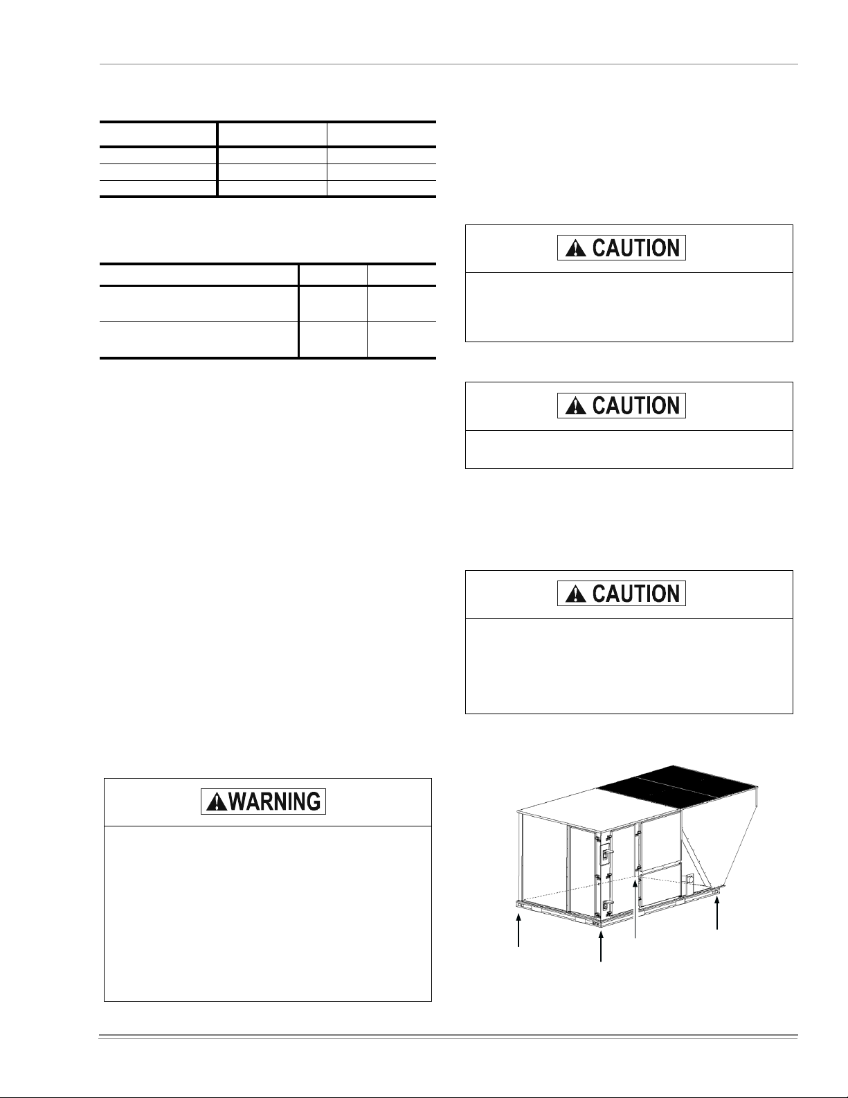
PRECEDING INSTALLATION
1. Remove the two screws holding the brac ket s in t he front,
rear and compressor side fork-lif t sl ots.
Bracket
Screws
Turn down
FIGURE 1 - UNIT SHIPPING BRACKET
8 Unitary Products Group

035-19046-002-B-0104
2. Turn each bracket toward the ground and the protective
plywood cov e rin g w ill d ro p to the gr ound.
3. Remove the condenser coil external protective covering
prior to operati on.
4. Remove the toolless doorknobs and instruction packet
prior to installation.
Toolless
Doorknobs
Installation
Instruction
Packet
LIMITATIONS
These units must be installed in accordance with the following:
In U.S.A.
1. National Electrical Code, ANSI/NFPA No. 70 - Latest
2. National Fuel Gas Code, ANSI Z223.1 - Latest Edition
3. Gas-Fired Central Furnace Standard, ANSI Z21.47a. -
4. Local building codes, and
5. Local gas utility requirem ents
In Canada
1. Canadian Electrical Code, CSA C22.1
2. Installation Codes, CSA - B149.1.
3. Local plumbing and waste water codes, and
4. Other applicable local codes.
:
Edition
Latest Edition
:
FIGURE 2 - COMPRESSOR SECTION
This product must be installed in strict compliance
with the enclosed installation instructions and any
applicable local, state and national codes including,
but not limited to, building, electrical, and mechanical codes.
The furnace and its individual shut-off valve must be
disconnected from the gas supply piping system
during any pressure testing at pressures in excess
of 1/2 PSIG.
Pressures greater than 1/2 PSIG will cause gas
valve damage resulting in a hazardous condi tion. If it
is subjected to a pressure greater than 1/2 PSIG, the
gas valve must be replac ed.
The furnace must be isolated from the gas supply
piping system by closing its individual manual shutoff valve during any pressure testing of the gas supply piping system at test pressures equal to or less
than 1/2 PSIG.
Refer to Tables 1 & 2 for unit appli cation data.
After installation, gas fired units must be adjusted to obtain a
temperature rise within the range specified on the unit rating
plate.
If components are to be added to a unit to meet local codes,
they are to be installed at the dealer’s and/or customer’s
expense.
Size of unit for propos ed installation should be based on heat
loss/heat gain calculation made according to the methods of
Air Conditioning Contractors of America (ACCA).
This furnace is not to be used for temporary heating of buildings or structures under construction.
Unitary Products Group 9
035-19046-002-B-0104
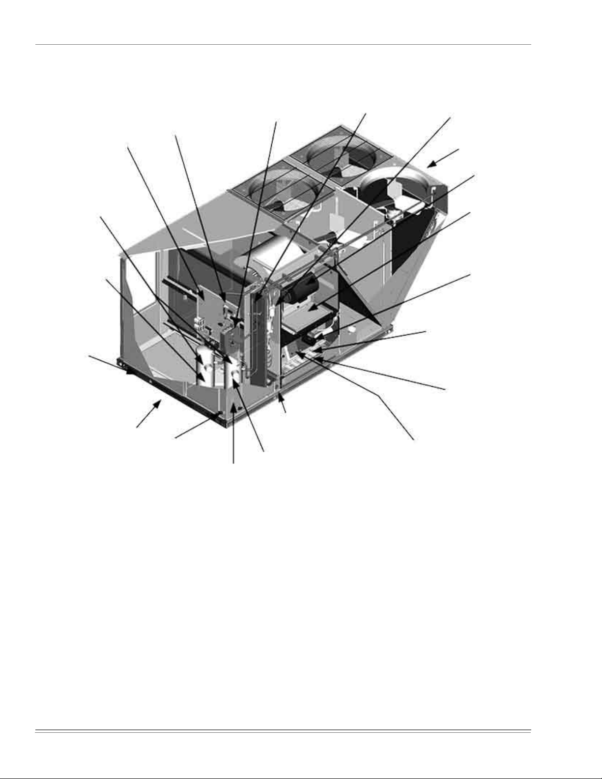
Second model
nameplate inside
hinged access panel
Dual stage cooling
for maximum comfort
Compressor #2
access (high-
efficiency compressor
w/crankcase heater)
Base rails w/forklift
slots (three sides)
and lifting holes
"Simplicity™" Control
board w/screw
connectors for T-stat
wiring and Network
connection
Disconnect
location
(optional disconnect switch)
Filter access
(2" throw-away)
Filter drier
(solid core)
Condenser
Section
Belt-drive blower
motor
Slide out motor
and blower
assembly for easy
adjustment and
service
Power ventor
motor
20-gauge
aluminized steel tubular
heat exchanger for long
life (stainless steel option)
Roof curbs in eight and
fourteen-inch heights.
Roof curbs for
transitioning from York
Sunline™ footprint to
the DM/DH/DJ/DR Series
footprint are available
(field-installed accessory)
Tool-less door
latch
Side entry power
and control wiring
knockouts
Slide-out drain pan
with brass 3/4" FPT
connection
Compressor #1 access
(high-efficiency
compressor w/
crankcase heater)
FIGURE 3 - PREDATO R MAGNUM COMPONENT LOCATION
Two-stage gas heating to
maintain warm,
comfortable temperature
Intelligent control
board for safe and
efficient operation
10 Unitary Products Group
035-19046-002-B-0104
A
D
B
C
LEFT
FRONT
TABLE 1: UNIT VOLTAGE LIMITATIONS
Power Rating
208/230-3-60 187 252
460-3-60 432 504
575-3-60 540 630
*.
Utilization range “A” in accordance with ARI Standard 110.
*
Minimum Maximum
TABLE 2: UNIT TEMPERATURE LIMITATIONS
Temperature Min. Max.
Wet B ulb Temperature (°F) of Air on
Evapora tor C oil
Dry Bulb Temperature (°F) of Air on
Condens er Coil
*.
A low ambient acc essory is available for operation
down to -20 °F.
57 72
*
0
125
LOCATION
Use the following guidelines to select a suitable location for
these units:
1. Unit is designed for outdoor installation only.
2. Condenser coils must have an unlimited supply of air.
Where a choice of locat ion is possible, position the unit
on either north or east side of building.
3. Suitable for mounting on roof curb.
RIGGING AND HANDLING
Exercise care when moving the unit. Do not remove any
packaging until the unit is near the place of installation. Rig
the unit by attaching chain or cable slings to the lifting holes
provided in the base rails. Spreader bars, whose length
exceeds the largest dimension across the unit, MUST be
used across the top of the unit.
If a unit is to be installed on a roof curb other than a
YORK roof curb, gasketing must be applied to all
surfaces that come in contact with the unit underside.
Before lifting, make sure the unit weight is distributed equall y on the riggi ng cables so it wil l lift evenl y.
Units may be moved or lifted with a forklift. Slotted openings
in the base rails are prov ided for this purpose.
LENGTH OF FORKS MUST BE A MINIMUM OF 60
INCHES.
4. For ground level install ation, use a level concret e slab
with a minimum thickness of 4 inches. The length and
width should be at lea st 6 in ches greater than the unit
base rails. Do not tie slab to the building foundation.
5. Roof structures must be ab le to sup port t he weight of t he
unit and its options/accessories. Unit must be installed
on a solid, level roof curb or appropriate ang le i ron
frame.
6. Maintain level tolerance to 1/2” across the entire width
and length of unit.
Excessive exposure of this furnace to contaminated
combustion air may result in equipment damage or
personal injury. Typical contaminates include: permanent wave soluti on, chlorinated waxes and cleaners, chlorine based swimming pool chemicals, water
softening chemicals, carbon tetrachloride, Halogen
type refrigerants, cleaning solvents (e.g. perchloroethylene), printing inks, paint removers, varnishes,
hydrochloric acid, cements and glues, antistatic fabric softeners for clothes dryers, masonry acid washing materials.
All panels must be secured in place when the unit is
lifted.
The condenser coils should be protected from rigging cable damage with plywood or other suitable
material.
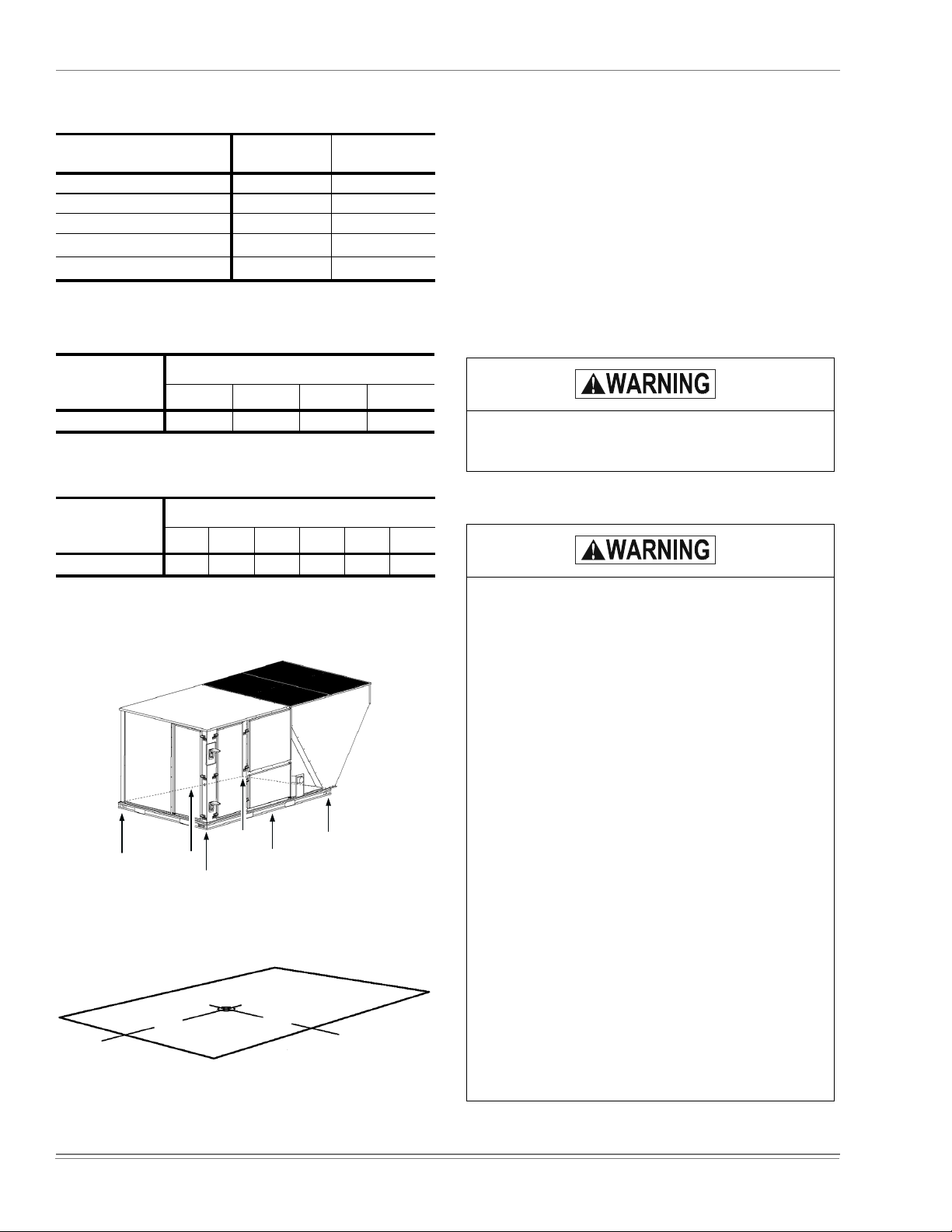
FIGURE 4 - UNIT 4 POINT LOAD
Unitary Products Group 11
035-19046-002-B-0104
TABLE 3: UNIT WEIGHTS
Model DJ150
Cooling Unit Only
w/Economizer
w/Power Exhaust
w/Gas Heat
*
w/Electric Heat
*.
8 Tube Heat Exchanger
†.
54 kW heat er
†
Shipping
Weight (lb.)
1415 1400
85 84
150 148
110 110
49 49
TABLE 4: 4 POINT LOAD WEIGHT
Model
ABCD
DJ150
*.
Weights include largest gas heat option.
282 323 424 371
Locati on (lbs .)
TABLE 5: 6 POINT LOAD WEIGHT
Model
ABCDEF
DJ150
*.
Weights include largest gas heat option.
184 201 220 289 264 242
Location (lbs .)
Operating
Weight
*
*
(lb.)
CLEARANCES
All units require particular clearances for proper operation
and service. Installer must make provisions for adequate
combustion and ventilation air in accordance with section 5.3
of Air f or Combustion and Ventil ation of th e National Fuel G as
Code, ANSI Z223.1 – Latest Edition (in U.S.A.), or Sections
7.2, 7.3, or 7.4 of Gas Installation Codes, CSA-B149.1 (in
Canada) - Latest Edition, and/or applicable provisions of the
local building codes. Refer to Table 6 for clearances required
for combustible construction, servicing, and proper unit operation.
Do not permit overhanging structures or shrubs to
obstruct condenser air discharge outlet, combustion
air inlet or vent outlet s.
Excessive exposure to contaminated combustion air
will result in safety and performance related problems. To maintain combustion air quality, the recommended source of combustion air is the outdoor air
supply. The outdoor air supplied for combustion
should be free from contaminants due to chemical
exposure that may be present from the following
sources.
• Commercial buildings
• Indoor pools
• Laundry rooms
• Hobby or craft rooms
• Chemical st orage areas
LEFT
A
B
C
F
FIGURE 5 - UNIT 6 POINT LOAD
FRONT
D
E
The following substances should be avoided to
maintain outdoor combustion air quality.
• Permanent wave solutions
• Chlorinated waxes and cleaners
• Chlorine based swimming pool cleaners
• W ater softening chemicals
• De-ici ng salts or chemicals
• Carbon tetrachloride
• Halogen ty pe refrigerants
• Cleaning solvents (such as perchloroethylene)
47-½"
25-½"
• Print ing inks, paint removers, varnishes, etc.
• Hydrochloric acid
LEFT
FRONT
FIGURE 6 - UNIT CENTE R OF GRAVITY
• Cements and glues
• Anti-static fabric softeners for clothes dryers
• Masonry acid washing materials
12 Unitary Products Group

035-19046-002-B-0104
119-7/16
30-11/32
50-3/4
4-1/4
59
LEFT
FIGURE 7 - UNIT DIMENSIONS
DETAIL A
5 - 1 / 4
G a s P i p e I n l e t
1 7 - 1 3 / 1 6
30-3/16
24-3/16
B a s e
P a n
Power
Entry
2-1/2
Control
Entry 7/8
17-3/16
6-3/16
Con-
venience
Outlet
Con-
venience
Outlet
Power
Entry
7/8
27
DETAIL B
For Drain Dimensions
See Detail C
89
FRONT
3 - 3 / 4
See Detail A
2 - 3 / 8
11-1/2
For
Baserail
Dimensions
See
Detail B
V i e w o f W a l l A c r o s s f r o m C o i l
TABLE 6: UNIT CLEARANCES
*
Top
†
Front
‡
Rear
*.
Units must be installe d outdoors. Overha nging struc-
72”
36”
36”
Bottom
Right
Left
DETAIL C
12”
36”
**
0”
5 - 3 / 8
3 - 9 / 1 6
ture or shrubs should not obstruct condenser air discharge outlet.
†.
The products of combusti on must not be allowed to
accumu late within a confined space and re-circulate.
‡.
To remove the slid e-out drain pan, a rear clearance of
sixty inches is required. If spac e is unavailable, the
drain pan can be removed through the front by separat-
NOTE: If the unit includes gas heating, locate the unit so
the flue exhaust is at least:
• Three (3) feet ab ove a ny f orced a ir i nlet locat ed with in 10
horizontal feet (excluding those integral to the unit).
ing the corner wall.
**.
Units may be installed on combustible floors made from
wood or class A, B or C roof covering materials.
• Four (4) feet below, four (4) horizontal feet from, or one
(1) foot above any door or grav ity air inlet into the building.
NOTE: A one-inch clearance must be provided between
any combustible material and the supply ductwork
for a distance of 3 feet from the unit.
• Four (4) feet from elect ri c m eters, gas meters, regulators, and relief equ ipment.
Unitary Products Group 13
035-19046-002-B-0104
6
.
32-11/16
6-13/16
21-3/16
19-3/16
17-3/16
6-13/16
LEFT
7-1/8
14-
23/32
16-3/8
18-1/16
19-5/8
Return
Air
18
27-1/2
Bottom
Condensate
Entry
FRONT
Supply
Air
21
Bottom
Power, Control
and
Convenience
Outlet Wiring
Entries
6-13/16
24
12-15/1
Bottom Gas
Supply Entry
63-1/2
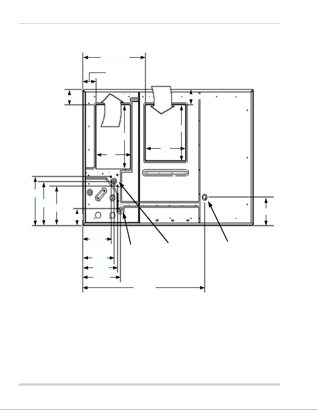
FIGURE 8 - BOTTOM DUCT OPENINGS (FROM ABOVE)
14 Unitary Products Group

035-19046-002-B-0104
18-1/4
5-5/32
Supply
Air
28-1/4
Dot Plugs
Return
Air
18-1/4
28-1/4
18-1/16
2-31/32
31-11/16
FIGURE 9 - REAR DUCT DIMENSIONS
DUCTWORK
Ductwork should be designed and sized according to the
methods in Manual D of the Air Conditioning Contractors of
America (ACCA) or as recommended by any other recognized authority such as ASHRAE or SMACNA.
A closed return duct system should be u sed. Th is will not
preclude use of economizers or outdoor fresh air intake. The
supply and return air duct connections at the unit should be
made wit h fl exib le joints to minimiz e noi s e.
The supply and return air duct systems should be designed
for the CFM and static press ure requi rement s of the job. They
should NOT be sized to match the dimensions of the duct
connections on t he unit.
Refer to Figure 8 for bottom air duct openings. Refer to Figure 9 for rear air duct openings.
DUCT COVERS
Units are shipped with the side duct openings covered and a
covering over the bottom of the unit. For bottom duct application, no duct cover changes are necessary. For side duct
application, remove the side duct covers and install over the
bottom duct openings. The panels removed from the side
duct connecti ons are designed to be reused by securing each
panel to its respective downflow opening. But keep in mind
that the supply panel is installed with the painted surface UP,
facing the heat exchanger, while the return panel is installed
with the painted surface DOWN, facing the downflow duct
opening. The supply panel is secured with the bracket
(already in place from the facto ry) and two screws. I t’s a snug
fit for the panel when sliding it between the heat exchanger
and unit bottom, but there is room. The return panel is
secured with four screws .
Unitary Products Group 15

035-19046-002-B-0104
R I G H T
8 0 - 5 / 8
2 0
2 0
6
S U P P L Y
I N S U L A T E D D E C K U N D E R
C O N D E N S E R S E C T I O N
2 T Y P .
3 0
5 0 - 1 / 2
R E T U R N
8 o r 1 4
I N S U L A T E D D E C K U N D E R
C O M P R E S S O R S E C T I O N
FIGURE 10 - PREDATOR MAGNUM ROOF CURB DIMENSIONS
2 T Y P
2 3
5 0 - 1 / 2
7 6 - 5 / 8
F R O N T
3 0 - 1 / 2
R E T U R N
9 4
4
S U P P L Y
F R O N T
2 6
8 0 - 5 / 8
1 0
5 9 - 1 / 4
6 4 - 1 / 4
R I G H T
FIGURE 11 - SUNLINE™ TO PREDATOR
MAGNUM TRANSITION ROOF CURBS
When fastening ductwork to side duct flanges on
unit, insert screws through duct flanges only. DO
NOT insert screws through casing. Outdoor ductwork must be insulated and water-proofed.
FIGURE 12 - SIDE PANELS WITH HO LE PL U GS
Note orientation. Panel is “insulation” side up.
16 Unitary Products Group
 Loading...