

Page 1

YASNAC PC NC
Operating Manual
Version: Beta 1.0
Page 2

YASNAC PCNC Operating Manual Introduction
SAFETY INFORMATION
PRECAUTIONS
1. Read this instruction manual in its en ti rety before using the op era ti ng functions availabl e in the
YASNAC PCNC.
2. The following warning symbols are used to indicate precautions that the user must be aware of
to safely use this equipment. Failure to follow these preca ut ions can result in serious or possi bly
even fatal injury and damage to pro duc ts or related equipment or systems.
WARNING
WARNING
WARNING
This sym b ol indica tes the pre s en ce of a potentially hazardous condition which, if not avoided,
could result in serious personal injury or death.
This precautionary symbol appears in labels attached to YASNAC products to alert the user to
conditions requiri ng concern for safety.
SPECIAL SAFETY NOTE: This symbol indicates that ELECTRICAL SHOCK HAZARD
condition exists. DO NOT TOUCH any electrical connection terminals when the power is on, and
for at least 5 minutes after switching off the power supply. Warning label is located on the PCNC
PCNC Unit
xxxxxxxxx
xxxxxxxxx
xxxxxxxxx
xxxxxxxxx
xxxxxxxxx
WARNING LABEL
NOTICE
Printed _______. 1999. The informatio n contained within thi s doc ument is the proprietary property of
Yasakawa Electric America, I nc. , and ma y not be c opied, reproduced or tra nsm it te d t o other parties without
the expressed wr itte n authorization of Yasakawa Electric America, Inc.
No pattent liability is assumed with respect to the uses of the information contained herein. Moreover,
becaus e Yaskawa is constantly improving i ts high quality product, the informati o n contained in this manual
is subject to chan ge without notice. Every precaution h as be en taken in the prepa ra ti on of this document .
i
Page 3

YASNAC PCNC Operating Manual Introduction
INFORMATION INDICATORS
The following symbols are used in this operating manual to empha siz e particular inform at ion to the user:
Indicates important information to be remembered, i.e., precautionary alarm
POINT
displays to prevent damaging devices.
SUPPLEMENT
TERMS
Indicates supplementary material.
Indicates definitions of terminology that has not been explained before.
NOTES REGARDING SAFE OPERATION
It is important that the user should read this manual before inst al li ng, operating, perfor mi ng any
mainten ance or ins p ecting th e
<$61$&3&1&
Also, the functions and performance of a NC machine tool
are not determine d by t he CNC unit itself, therefore thoroughly read and familiarize yourself with the
machine builder’s documentation conc erning the safe an d mo st effic ie nt wa ys to u se the machine too l.
Nevertheless, Yasa kawa assumes no responsibility for da ma ge s resulting from the use of the informat io n
contained within this publication.
ii
Page 4

YASNAC PCNC Operating Manual Introduction
TABLE OF CONTENTS
1. OUTLINE OF THE PRODUCT
1.1 OUTLINE of the YASNAC SYSTEM . . . . . . . . . . . . . . . . . . . . . . . . . . . . . . . .1 -2
1.1.1 System Configuration . . . . . . . . . . . . . . . . . . . . . . . . . . . . . . . . . . . . . . . 1-2
1.1.2 Environmental Requirements . . . . . . . . . . . . . . . . . . . . . . . . . . . . . . . . . 1-3
1.1.3 Machine Operation Panel . . . . . . . . . . . . . . . . . . . . . . . . . . . . . . . . . . . . 1-4
1.1.4 General Specifications . . . . . . . . . . . . . . . . . . . . . . . . . . . . . . . . . . . . . . 1-5
1.2 PROTECTIVE FUNCTIONS . . . . . . . . . . . . . . . . . . . . . . . . . . . . . . . . . . . . . . .1-9
1.2.1 Emergency Stop . . . . . . . . . . . . . . . . . . . . . . . . . . . . . . . . . . . . . . . . . . . 1-9
1.2.2 Overtravel . . . . . . . . . . . . . . . . . . . . . . . . . . . . . . . . . . . . . . . . . . . . . . . . 1-9
1.2.3 Stored St roke Limit. . . . . . . . . . . . . . . . . . . . . . . . . . . . . . . . . . . . . . . . . 1-10
1.2.4 Interlock Inputs. . . . . . . . . . . . . . . . . . . . . . . . . . . . . . . . . . . . . . . . . . . . 1-12
2. BASIC OPERATION OF YASN AC PCNC
2.1 GENERAL OPERATION FLOW . . . . . . . . . . . . . . . . . . . . . . . . . . . . . . . . . . . 2-4
2.2 INSECTION BEFORE TURNING THE POWER ON . . . . . . . . . . . . . . . . . . 2-4
2.2.1 Inspection of the PCNC unit. . . . . . . . . . . . . . . . . . . . . . . . . . . . . . . . . . 2-6
2.2.2 Prepartion before Turning the Power ON. . . . . . . . . . . . . . . . . . . . . . . . 2-7
2.3 TURNING THE POWER ON/OFF. . . . . . . . . . . . . . . . . . . . . . . . . . . . . . . . . . 2-4
AND INSPECTION AFTER POWER ON/OFF . . . . . . . . . . . . . . . . . . . . . . . .2-8
2.3.1 Procedure for Turning the Power ON . . . . . . . . . . . . . . . . . . . . . . . . . . . 2-8
2.3.2 Checking the Motors for Abnormalities. . . . . . . . . . . . . . . . . . . . . . . . . 2-9
2.3.3 Procedure for Turning the Power OFF. . . . . . . . . . . . . . . . . . . . . . . . . . 2-9
2.3.4 Inspection of the Battery . . . . . . . . . . . . . . . . . . . . . . . . . . . . . . . . . . . . . 2-10
iii
Page 5

YASNAC PCNC Operating Manual Introduction
2.4 MANUAL OPERATION (1) . . . . . . . . . . . . . . . . . . . . . . . . . . . . . . . . . . . . . . . 2-11
2.4.1 Manual Rapid Traverse (RAPID). . . . . . . . . . . . . . . . . . . . . . . . . . . . . . 2-12
2.4.2 Jog Feed (JOG). . . . . . . . . . . . . . . . . . . . . . . . . . . . . . . . . . . . . . . . . . . . 2-13
2.4.3 Step Feed (STEP) . . . . . . . . . . . . . . . . . . . . . . . . . . . . . . . . . . . . . . . . . . 2-13
2.4.4 Handle Feed (HANDLE)* . . . . . . . . . . . . . . . . . . . . . . . . . . . . . . . . . . . 2-13
2.5 MANUAL OPERATION(2) . . . . . . . . . . . . . . . . . . . . . . . . . . . . . . . . . . . . . . . 2-15
2.5.1 Simultaneous 2- o r 3-axis Handle Feed* . . . . . . . . . . . . . . . . . . . . . . . . 2-15
2.5.2 Manual Reference Point Return . . . . . . . . . . . . . . . . . . . . . . . . . . . . . . . 2-16
2.5.3 Manual Reference Point Ret urn t o the Second Reference Point l . . . . . 2-18
2.5.4 1-line MDI . . . . . . . . . . . . . . . . . . . . . . . . . . . . . . . . . . . . . . . . . . . . . . . 2-19
2.6 AUTOMATIC OPERATION (1) . . . . . . . . . . . . . . . . . . . . . . . . . . . . . . . . . . . . 2-20
2.6.1 Preparation of Automatic Operation. . . . . . . . . . . . . . . . . . . . . . . . . . . . 2-20
2.6.2 Memory Operation . . . . . . . . . . . . . . . . . . . . . . . . . . . . . . . . . . . . . . . . . 2-22
2.6.3 MDI Operation . . . . . . . . . . . . . . . . . . . . . . . . . . . . . . . . . . . . . . . . . . . . 2-23
2.6.4 Feed Hold . . . . . . . . . . . . . . . . . . . . . . . . . . . . . . . . . . . . . . . . . . . . . . . . 2-23
2.6.5 Override . . . . . . . . . . . . . . . . . . . . . . . . . . . . . . . . . . . . . . . . . . . . . . . . . 2-24
2.7 AUTOMATIC OPERATION (2) . . . . . . . . . . . . . . . . . . . . . . . . . . . . . . . . . . . . 2-25
2.7.1 Optional Stop . . . . . . . . . . . . . . . . . . . . . . . . . . . . . . . . . . . . . . . . . . . . . 2-25
2.7.2 Optional Block Skip . . . . . . . . . . . . . . . . . . . . . . . . . . . . . . . . . . . . . . . . 2-25
2.7.3 Dry Run. . . . . . . . . . . . . . . . . . . . . . . . . . . . . . . . . . . . . . . . . . . . . . . . . . 2-26
2.7.4 Display Lock and Machine Lock . . . . . . . . . . . . . . . . . . . . . . . . . . . . . . 2-26
2.7.5 Auxiliary Function Lock. . . . . . . . . . . . . . . . . . . . . . . . . . . . . . . . . . . . . 2-26
2.7.6 Z-axis Command Neglect . . . . . . . . . . . . . . . . . . . . . . . . . . . . . . . . . . . 2-27
2.7.7 4th-axis Command Neglect . . . . . . . . . . . . . . . . . . . . . . . . . . . . . . . . . . 2-27
2.7.8 5th-axis Command Neglect . . . . . . . . . . . . . . . . . . . . . . . . . . . . . . . . . . 2-28
iv
Page 6

YASNAC PCNC Operating Manual Introduction
2.8 OPERATION INTERVENTION (during automatic operation) . . . . . . . . . . . . 2-29
2.8.1 Manual Operation Intervention (during automati c ope ra ti on) . . . . . . . . 2-3 0
2.8.2 MDI Operation Intervention ( duri ng automatic operation) . . . . . . . . . . 2-30
2.8.3 Automatic Handle Mode Offset . . . . . . . . . . . . . . . . . . . . . . . . . . . . . . . 2-30
2.8.4 Manual Absolute. . . . . . . . . . . . . . . . . . . . . . . . . . . . . . . . . . . . . . . . . . . 2-32
3. BASICS OF DISPLAY AND WRITING OPERATION
3.1 USER INTERFACE OVERVIEW . . . . . . . . . . . . . . . . . . . . . . . . . . . . . . . . . . . 3-6
3.1.0 User InterfaceOverview . . . . . . . . . . . . . . . . . . . . . . . . . . . . . . . . . . . . . 3-6
3.1.1 Status Bar . . . . . . . . . . . . . . . . . . . . . . . . . . . . . . . . . . . . . . . . . . . . . . . . 3-6
3.1.2 Battery Indicator. . . . . . . . . . . . . . . . . . . . . . . . . . . . . . . . . . . . . . . . . . . 3-6
3.1.3 NC Execution Status. . . . . . . . . . . . . . . . . . . . . . . . . . . . . . . . . . . . . . . . 3-6
3.1.4 Motion Status . . . . . . . . . . . . . . . . . . . . . . . . . . . . . . . . . . . . . . . . . . . . . 3-7
3.1.5 Alarm Message. . . . . . . . . . . . . . . . . . . . . . . . . . . . . . . . . . . . . . . . . . . . 3-7
3.1.6 Warning Message . . . . . . . . . . . . . . . . . . . . . . . . . . . . . . . . . . . . . . . . . . 3-7
3.1.7 Time/Dat e . . . . . . . . . . . . . . . . . . . . . . . . . . . . . . . . . . . . . . . . . . . . . . 3-7
3.1.8 Mode / MDI / Tool Bar. . . . . . . . . . . . . . . . . . . . . . . . . . . . . . . . . . . . . . 3-8
3.1.9 Mode Indicator . . . . . . . . . . . . . . . . . . . . . . . . . . . . . . . . . . . . . . . . . . . . 3-18
3.1.10 Menu Bar . . . . . . . . . . . . . . . . . . . . . . . . . . . . . . . . . . . . . . . . . . . . . . . . 3-14
3.2 RECURRING COMPONENTS . . . . . . . . . . . . . . . . . . . . . . . . . . . . . . . . . . . . . 3-14
3.2.1 Positioning the Cursor . . . . . . . . . . . . . . . . . . . . . . . . . . . . . . . . . . . . . . 3-16
3.2.2 Nest Level Display . . . . . . . . . . . . . . . . . . . . . . . . . . . . . . . . . . . . . . . . . 3-17
3.2.3 Shortcuts . . . . . . . . . . . . . . . . . . . . . . . . . . . . . . . . . . . . . . . . . . . . . . . 3-17
3.2.4 Number Field . . . . . . . . . . . . . . . . . . . . . . . . . . . . . . . . . . . . . . . . . . . . . 3-18
3.2.5 File Browser . . . . . . . . . . . . . . . . . . . . . . . . . . . . . . . . . . . . . . . . . . . . . . 3-19
v
Page 7

YASNAC PCNC Operating Manual Introduction
3.3 RUN MENU . . . . . . . . . . . . . . . . . . . . . . . . . . . . . . . . . . . . . . . . . . . . . . . . 3-21
3.3.1 Production Screen. . . . . . . . . . . . . . . . . . . . . . . . . . . . . . . . . . . . . . . . . . 3-22
3.3.2 Proveout Screen . . . . . . . . . . . . . . . . . . . . . . . . . . . . . . . . . . . . . . . . . . . 3-23
3.3.3 NC Switch Screen. . . . . . . . . . . . . . . . . . . . . . . . . . . . . . . . . . . . . . . . . . 3-29
3.3.4 Timers Screen . . . . . . . . . . . . . . . . . . . . . . . . . . . . . . . . . . . . . . . . . . . . . 3-30
3.4 PROGRAM MENU . . . . . . . . . . . . . . . . . . . . . . . . . . . . . . . . . . . . . . . . . . . . . . 3-32
3.4.1 File Screen . . . . . . . . . . . . . . . . . . . . . . . . . . . . . . . . . . . . . . . . . . . . . . . 3-32
3.4.2 Editor Screen. . . . . . . . . . . . . . . . . . . . . . . . . . . . . . . . . . . . . . . . . . . . . . 3-38
3.4.3 List Screen . . . . . . . . . . . . . . . . . . . . . . . . . . . . . . . . . . . . . . . . . . . . . . . 3-45
3.4.4 Macro Variables . . . . . . . . . . . . . . . . . . . . . . . . . . . . . . . . . . . . . . . . . . . 3-47
3.5 TOOL MENU . . . . . . . . . . . . . . . . . . . . . . . . . . . . . . . . . . . . . . . . . . . . . . . . . . 3-49
3.5.1 Offset Screen . . . . . . . . . . . . . . . . . . . . . . . . . . . . . . . . . . . . . . . . . . . . . 3-49
3.5.2 Magazine Screen. . . . . . . . . . . . . . . . . . . . . . . . . . . . . . . . . . . . . . . . . . . 3-52
3.6 SETUP MENU . . . . . . . . . . . . . . . . . . . . . . . . . . . . . . . . . . . . . . . . . . . . . . . . . . 3-53
3.6.1 Workshift Screen. . . . . . . . . . . . . . . . . . . . . . . . . . . . . . . . . . . . . . . . . . . 3-53
3.6.2 Four (4) Position Screen. . . . . . . . . . . . . . . . . . . . . . . . . . . . . . . . . . . . . 3-55
3.6.3 One (1) Position Screen . . . . . . . . . . . . . . . . . . . . . . . . . . . . . . . . . . . . . 3-56
3.7 UTILITIES MENU. . . . . . . . . . . . . . . . . . . . . . . . . . . . . . . . . . . . . . . . . . . . . . . 3-57
3.7.1 Log in Screen . . . . . . . . . . . . . . . . . . . . . . . . . . . . . . . . . . . . . . . . . . . . . 3-57
3.7.2 System Screen. . . . . . . . . . . . . . . . . . . . . . . . . . . . . . . . . . . . . . . . . . . . . 3-59
3.7.3 Maintenance Screen . . . . . . . . . . . . . . . . . . . . . . . . . . . . . . . . . . . . . . . . 3-60
3.7.4 Configuration Screen . . . . . . . . . . . . . . . . . . . . . . . . . . . . . . . . . . . . . . . 3-61
3.7.5 Backup and Restore Screen . . . . . . . . . . . . . . . . . . . . . . . . . . . . . . . . . . 3-63
3.7.6 CPU Monitor Screen. . . . . . . . . . . . . . . . . . . . . . . . . . . . . . . . . . . . . . . . 3-65
3.7.7 Setting Parameters Screen . . . . . . . . . . . . . . . . . . . . . . . . . . . . . . . . . . . 3-67
vi
Page 8

YASNAC PCNC Operating Manual Introduction
3.7.8 NC Parameters Screen . . . . . . . . . . . . . . . . . . . . . . . . . . . . . . . . . . . . . . 3-70
3.7.9 Machine Setup Screen . . . . . . . . . . . . . . . . . . . . . . . . . . . . . . . . . . . . . . 3-71
3.7.10 Pitch Error Screen. . . . . . . . . . . . . . . . . . . . . . . . . . . . . . . . . . . . . . . . . . 3-72
3.7.11 Torque Ripple Screen . . . . . . . . . . . . . . . . . . . . . . . . . . . . . . . . . . . . . . . 3-74
3.7.12 Parameter Search Screen . . . . . . . . . . . . . . . . . . . . . . . . . . . . . . . . . . . . 3-75
3.7.13 High Speed Cutting Screen . . . . . . . . . . . . . . . . . . . . . . . . . . . . . . . . . . 3-77
3.7.14 User Install Screen . . . . . . . . . . . . . . . . . . . . . . . . . . . . . . . . . . . . . . . . . 3-78
3.7.15 MTB Install Screen. . . . . . . . . . . . . . . . . . . . . . . . . . . . . . . . . . . . . . . . . 3-81
3.7.16 PLC Parameters Screen . . . . . . . . . . . . . . . . . . . . . . . . . . . . . . . . . . . . . 3-82
3.7.17 PLC Diagnosis Screen . . . . . . . . . . . . . . . . . . . . . . . . . . . . . . . . . . . . . . 3-83
3.7.18 Ladder Monitor Screen. . . . . . . . . . . . . . . . . . . . . . . . . . . . . . . . . . . . . . 3-88
3.7.19 Switch Label Screen . . . . . . . . . . . . . . . . . . . . . . . . . . . . . . . . . . . . . . . . 3-88
3.8 ALARM MENU. . . . . . . . . . . . . . . . . . . . . . . . . . . . . . . . . . . . . . . . . . . . . . . . . 3-91
3.8.1 NC Alarm Screen . . . . . . . . . . . . . . . . . . . . . . . . . . . . . . . . . . . . . . . . . . 3-91
3.8.2 PLC Alarm Screen . . . . . . . . . . . . . . . . . . . . . . . . . . . . . . . . . . . . . . . . . 3-93
3.8.3 Alarm History Screen. . . . . . . . . . . . . . . . . . . . . . . . . . . . . . . . . . . . . . . 3-95
3.9 Help Menu . . . . . . . . . . . . . . . . . . . . . . . . . . . . . . . . . . . . . . . . . . . . . . . . . . 3-96
3.10 MMI Map Screen . . . . . . . . . . . . . . . . . . . . . . . . . . . . . . . . . . . . . . . . 3-96
3.11 Manual Screen . . . . . . . . . . . . . . . . . . . . . . . . . . . . . . . . . . . . . . . . . . 3-97
3.12 Offline Mode. . . . . . . . . . . . . . . . . . . . . . . . . . . . . . . . . . . . . . . . . . . . . . 3-98
3.13 Offline Mode Interface . . . . . . . . . . . . . . . . . . . . . . . . . . . . . . . . . . . . . . 3-98
4. MAINTENANCE
4.1 MAINTENANCE DATA . . . . . . . . . . . . . . . . . . . . . . . . . . . . . . . . . . . . . . . . . . 4-2
4.1.1 Checking the Status of Problems . . . . . . . . . . . . . . . . . . . . . . . . . . . . . . . .4-2
4.1.2 Checking the NC Information. . . . . . . . . . . . . . . . . . . . . . . . . . . . . . . . . . .4-3
4.1.3 Display of Alarm Information . . . . . . . . . . . . . . . . . . . . . . . . . . . . . . . . . .4-3
4.1.4 Cause of Alarm and Corrective Action. . . . . . . . . . . . . . . . . . . . . . . . . . . .4-4
vii
Page 9

YASNAC PCNC Operating Manual Introduction
4.1.5 Troubleshooting (1) . . . . . . . . . . . . . . . . . . . . . . . . . . . . . . . . . . . . . . . . . .4-5
4.1.6 Troubleshooting (2) . . . . . . . . . . . . . . . . . . . . . . . . . . . . . . . . . . . . . . . . . .4-12
4.1.7 Alarms Not Indicated by Alarm Numbers . . . . . . . . . . . . . . . . . . . . . . . . .4-16
4.1.8 PCNC Alarms Not Indicated by Alarm Numbers . . . . . . . . . . . . . . . . . . .4-28
4.1.9 Touch Screen Maintenance. . . . . . . . . . . . . . . . . . . . . . . . . . . . . . . . . . . . .4-28
4.1.10 Mode of PCNC Operation . . . . . . . . . . . . . . . . . . . . . . . . . . . . . . . . . . . . .4-29
4.1.11 Self-D i a gnosi s Func ti on . . . . . . . . . . . . . . . . . . . . . . . . . . . . . . . . . . . . . . .4-30
4.1.12 Hard Drive Mounting Replacement . . . . . . . . . . . . . . . . . . . . . . . . . . . . . .4-32
APPENDIX 1. LIST OF PCNC INPUT/OUTPUT SIGNALS
1.1 INPUT SIGNALS ( PLC > NC ). . . . . . . . . . . . . . . . . . . . . . . . . . . . . . . . . . . . . . . A1-2
1.2 OUTPUT SIGNALS ( NC > PLC ). . . . . . . . . . . . . . . . . . . . . . . . . . . . . . . . . . . . . A1-9
APPENDIX 2. ALARM TABLE
2.1 CLASSSIFICATION OF ALARMS . . . . . . . . . . . . . . . . . . . . . . . . . . . . . . . . . . . . A2-2
2.2 ALARM TABLE ( PCNC ) . . . . . . . . . . . . . . . . . . . . . . . . . . . . . . . . . . . . . . . . . . . A2-3
2.3 TROUBLESHOOTING. . . . . . . . . . . . . . . . . . . . . . . . . . . . . . . . . . . . . . . . . . . . . . A2-21
APPENDIX 3. PARAMETER TABLE . . . . . . . . . . . . . . . . . . . . . . . . . . . . . . . . . . . . . . A3-1
viii
Page 10

YASNAC PCNC Operating Manual Introduction
USING THIS MANUAL
This manual decribes the procedures for operating the
<$61$&3&1&
RELAT ED INFORMATION SOURCES
For additonal information, refer to the follow in g ma nuals:
TITLE OF DOCUMENT CONTENTS
YASNAC PCNC Programming Manual
(YEA-SIE-C844-2.2)
YASNAC PCNC/PLC Programming Manual
(YEA-SIE-C844-0.1)
YASNAC PCNC I/O Signal Manual
(YEA-SIE-C844-2.3)
YASNAC PCNC Connection Manual
(YEA-SIE-C844-0.2)
YASNAC PCNC Maintenance Manual
(YEA-SIE-C844-2.9)
.
PCNC Program creation instructions
PLC Program creation instructions
Describes functions between PCNC and PLC
Instructions for connecting PCNC with machines,
machine interface and peripheral equipment
Describes service and maintenance procedures.
ix
Page 11

YASNAC PCNC Operating Manual Introduction
CAUTIONS
This manual describes all the option functions (identified by the “*” sym bol ) but some of these may not
be available with your YASNAC PCNC. T o determine the option functions installed in your PCNC,
refer to the specification docume nt or manuals publishe d by t he machine tool buil der.
Unless otherwise specified, the follow i ng conditions apply in prog ramming explan ations and
programm i ng examples.
l
Metric system for input and metric system for output / movement
l
Zero point in the base coo rdi nate system
l
Reference point
Yaskawa has made every effort to de scribe individual func ti ons a nd their relationships to oth er fun ct ions
as accurate ly a s possible. However, there are many things that cannot or must not be performed and it is
not possible to describe al l of th ese . Accordingly, readers are requested to understand that un le ss it is
specifically stat ed that something can be pe rformed, it should be assumed that it cannot be perfor med.
Also, bear in mind that the performanc e a nd functions of an PCNC m a chine tool are not de te rm ined
solely by the PCNC unit. The entire contr ol system consists of the mechanical system, then machine
operatio n pa nel and other machine related equ ip ment in addition to the PCNC. Therefore, read the
manuals publ ished by the machine tool builder for detailed information rela ti ng t o the ma chine.
x
Page 12

YASNAC PCNC Operating Manual Chapter 1: Outline of YA SNAC System
1
Outline of the YASNAC System
Chapter 1 describes the outline of the YASNAC system and the operating features and functions that should be thoroughly understood for the safe and efficient operation of the system.
1.1 Outline of the YASNAC System . . . . . . . . . . . . . . . . . . . . . . . . . . . . . . . . . . . . . .1-2
1.1.1 System Configuration. . . . . . . . . . . . . . . . . . . . . . . . . . . . . . . . . . . . . . . . .1-2
1.1.2 Environmental Requirements . . . . . . . . . . . . . . . . . . . . . . . . . . . . . . . . . . .1-3
1.1.3 Machine Operation Panel . . . . . . . . . . . . . . . . . . . . . . . . . . . . . . . . . . . . . .1-4
1.1.4 General Specifications . . . . . . . . . . . . . . . . . . . . . . . . . . . . . . . . . . . . . . . .1-5
1.2 Protective Functions . . . . . . . . . . . . . . . . . . . . . . . . . . . . . . . . . . . . . . . . . . . . . . . .1-9
1.2.1 Emergency Stop . . . . . . . . . . . . . . . . . . . . . . . . . . . . . . . . . . . . . . . . . . . . .1-9
1.2.2 Overtravel. . . . . . . . . . . . . . . . . . . . . . . . . . . . . . . . . . . . . . . . . . . . . . . . . .1-9
1.2.3 Stored St roke Limit. . . . . . . . . . . . . . . . . . . . . . . . . . . . . . . . . . . . . . . . . . .1-10
1.2.4 Interlock Inputs. . . . . . . . . . . . . . . . . . . . . . . . . . . . . . . . . . . . . . . . . . . . . .1-12
1 - 1
Page 13
YASNAC PCNC Operating Manual Chapter 1: Outline of YA SNAC System
1.1 Outline of the YASNAC System
1.1.1 System Configuration
PCNC
Remote
Machine
Pendant
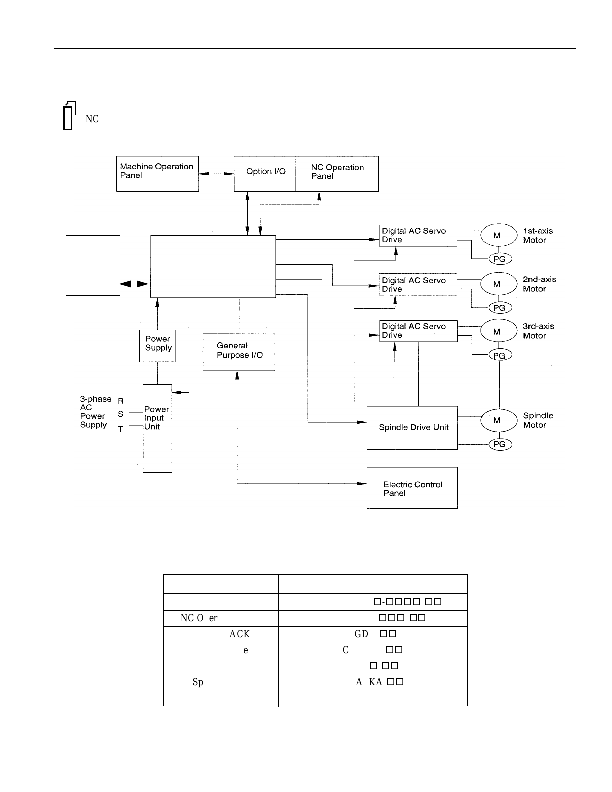
The configuration of the Y ASNAC PCNC system and the list of components are described below.
Unit
YASNAC PCNC
Unit
FIGURE 1.1.1.1: Standard Configuration of PCNC System
Table 1.1.1.1: List of YASNAC PCNC System Components
COMPONENT NAME MODEL NAME
CPU rack JZNC-JPCRKM-
NC Operation Panel JZNC-JPCOP-
SERVOPACK SGDC-
Spindle drive CIMR-M5
Servomotor SGMo-
Spindle motor UAASKA-
Remote Pendant TBA
o-oooo-oo
ooo-oo
oo
oo
oo
oo
1 - 2
Page 14

YASNAC PCNC Operating Manual Chapter 1: Outline of YA SNAC System
1.1.2 Environmental Requirements
Requirements for the installation of an PCNC unit are indicated below. Install the PCNC unit in a
location where only these requirements are satisfied to avoid possible malfunctioning.
CAUTION!
Avoid using it in an environment where it may be subject to high temperatures, high humidity, dust,
corrosive gases, vibration or physical impacts that may cause fire, electric shock or malfunction.
• Use the product in an environment meeti n g the following conditions:
• Free from gases or vapors that create a potentially explosive atmosphere.
• Free from oil, organic solvents, et c.
• Relative humidity in the range 10 to 90% RH, with no condensation.
• Ambient temperature in the 0°C to 55°C with no freezing.
(Installation site must not be exposed to direct sunlight, must be distanced from heat generating devices,
and must be indoors.)
2
• Vibration not exceeding 4.9 m/s
.
• Do not store the product in locations subje ct to rain, w ater droplets, harmful gases or liquid s.
Failure to observe this caution may result in product failure.
• Select a storage area indoors that is clean and meets the following temperature and humidity
requirements.
Ambient temperature: –15° C to 65° C (–5° F to 149° F)
Relative humidity: 10% to 90%
Failure to observe this caution may result in product failure.
(1) Ambient Temperature
For operation:0°C to 55°C
For storage and transportation:–15° C to 65° C
Install the PC NC unit in a location not subject to direct sunlight, distant from heat sources,
and indoors.
(2) Humidity
Relative humidi ty m ust be in the range of 10 to 90%RH (non -condensing).
(3) Vibration
During operation: Max. 4.9 m/s
2
1 - 3
Page 15

YASNAC PCNC Operating Manual Chapter 1: Outline of YA SNAC System
(4) Atmosphere
Avoid the following locations:
• Dusty places
• Places where concentration of coolant and/or organic solvent mist is ext remely high.
(5) Power Sou rce
Input voltage:AC (single-phase) 180V ~ 264V
Frequency:50/60 Hz –2 to +2 Hz
1.1.3 Machine Operation Panel
An example of t h e machine operation panel is indicate d below. Arra ngement and names of
switch es and indicator la mps vary according to the mach ine model. For deta ils, refer to the
machine tool man ua l.
FIGURE 1.1.3. 1: Example of Mac h i ne Operation Panel
1 - 4
Page 16
YASNAC PCNC Operating Manual Chapter 1: Outline of YA SNAC System
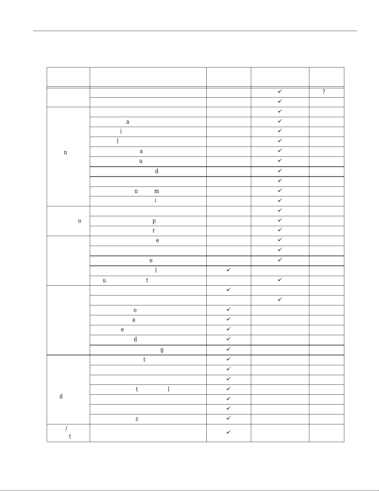
1.1.4 Gene ra l Speci fic ations
(1) Standard Specifications
CATEGORY ITEM AND FUNCTION
Controlled
axes
Input
command
Interpolation
Feed
Storage and
editing of
program
Operation
and
display
Input/Output
function
Number of simultaneously controlled axes
Maximum programmable value
Absolute/incremental programming
Automatic acceleration and deceleration
Controlled axes
Least i nput increment
Least output incre ment
Decimal point input
Input unit 10 times
Tape code
NC tape
Input format
Buffer register
Positioning
Linear interpol ation
Circular interpolation
Rapid traverse
Cutting feed
Dwell
Incremental feed
Program storage capacity
Number of programs
Program editing
Program number search
Sequence number search
Address search
MDI editing
Operation panel
MDI function
l-line MDI
Operation and display
Calendar display
Pop-up menu
Buzzer function
Input/Output interface
OPERATION
MANUAL
á
á
á
á
á
á
á
á
á
á
á
á
á
á
á
PROGRAMMING
MANUAL
á
á
á
á
á
á
á
á
á
á
á
á
á
á
á
á
á
á
á
á
SECTION
NO.
???
1 - 5
Page 17

YASNAC PCNC Operating Manual Chapter 1: Outline of YA SNAC System
CATEGORY ITEM AND FUNCTION
Tool function
Miscellaneous function
Tool offset
Coordinate
system
Operation
support
function
Programming
support
function
Safety
and
maintenance
Environment
requirements
Automatic return to reference point
Automa tic return to second reference point
Circular interpolation by R command
Self-diagnostics (always displayed)
Tool length offset
Tool position offset
Number of tool offset data sets
Manual return to reference point
Reference point return check
Return from reference point
Base coordinate system setting
Label sk ip
Single block
Optional stop
Optional block skip
Dry run
Machine lock
Miscellaneous function lock
Display lock
Manual absolute
Numerical value set-up
Break-point function
Operat ion mode
Feed hold
Repetitive circle interpolation
Subprogram
Exact stop check
Exact stop chec k mode
Emergency stop input
Overtravel
Axis interlock
Stored stroke limit
Power supply
Ambient temperature
Humidity
OPERATION
MANUAL
á
á
á
á
á
á
á
á
á
á
á
á
á
á
á
á
á
á
á
á
PROGRAMMING
MANUAL
á
á
á
á
á
á
á
á
á
á
á
á
á
á
á
á
á
SECTION
NO.
1 - 6
Page 18

YASNAC PCNC Operating Manual Chapter 1: Outline of YA SNAC System
(2) Option Spe cific a tions
CATEGORY ITEM AND FUNCTION
Controlled
axes
Least input/output increment of rotary axis
Input
command
Interpolation Helical interpolation
Feed
Storage
and editing
of program
Operation
and
display
Input/output
function and
device
Spindle, tool
and
miscellaneous
functions
T ool offset
Automatic third/fourth reference point return
Coordinate
system
Expanded number of workpiece coordinate
Number of controlled axes
Rotary axis cont rol
Inch/metric switching
Multi-active reg isters
Synchronized feed (solid tap)
High-speed mode operation
F1-digit
Simultaneous1-axis handle feed
Simultaneous 2-axis handle feed
Simultaneous 3-axis handle feed
Addition of program storage capaci ty
Addition of number of programs
Playback
Internal toggle switch
NC program drawing
Comment display func ti on
Tape reader without take-up reels
Tape reader with take-up reels
RS-232C interface
T4-digit command
Second miscellaneous function
Tool radius offset
Additi on of tool offset data sets
Manual second reference point return
Workpiece coordinate system setting
systems
Local coordinate system
Rotation of workpiece coordinate system
OPERATION
MANUAL
á
á
á
á
á
á
á
á
á
á
á
PROGRAMMING
MANUAL
á
á
á
á
á
á
á
á
á
á
á
á
á
á
á
á
á
á
á
á
SECTION
NO.
1 - 7
Page 19

YASNAC PCNC Operating Manual Chapter 1: Outline of YA SNAC System
Operation
support
function
Programming
support
function
Accuracy
correction for
mechanical
system
Automation
support
function
Safety and
maintenance
Optional block skip B
Automatic mode handle offset
Program restart
Automa tic tool length measuremen t (TLM)
Manual interruption point return
Canned cycle
Canned cycle B
Circle cutting
Macroprogram
Programmable mirror image
Scaling
Coordinate syst em rotation
Automa tic comer override
Programmable data input
Hole ma chining pattern cycle
Program copy
Stored pitch error compe nsa ti on
Unidirectional approach
Skip function
Tool life control function
Program interruption
Stored stroke limit B
Stored stroke limit C
á
á
á
á
á
á
á
á
á
á
á
á
á
á
á
á
á
á
á
á
á
á
á
1 - 8
Page 20

YASNAC PCNC Operating Manual Chapter 1: Outline of YA SNAC System
1.2 Protective Functions
1.2.1 Emergency Stop
Press the emergency stop button immediately if a problem occurs with the system or line. The
execution of all c om m ands stops instantaneously when the emergency stop button is pressed.
Servo power supply of the PCNC is shut OFF and dynamic br ake is applied to stop all
mechanical movement. In the emergency stop state, the PCNC is in the alarm stat e “3002”. If the
emergency stop signal is “opened”, the PCNC stops the en tire operation, and the SVMX and
BKX signals are “opened”.
PCNC
This operation is executed by setting the pins on the board. The pins differ between J300M
and J100M.
1.2.2 Overtravel
The overtravel function stops axis feed operation when an axis reaches the travel limit; for the
detection of travel limit, a limit switch and a dog are used and if an axis reaches the travel limit,
the limit switch outputs a signal a nd th e function stops axis feed operati on i n response to this
input. The axis rea ched and stopped at the tr avel limit can be moved manually into the axis movable range.
When the overtravel input is “opened”, axis movement is stopped in the manner as indicated in
Table 1.3. In response to thi s inpu t, the alarm output (ALM) i s “closed” and the corresponding
alarm message is di sp la ye d on the screen.
Table 1.2.1. 1: E mergency Related Signals
Signal Name Pin Setting
Emergency Stop Input CN12-19 pin on JZNC-JFC 10 board
SVMX CN12-17 pin on JZNC-JFC 10 board
BKX CN12-16 pin on JZNC-JFC 10 board
Table 1.2.2.1: Axis Stop Direction with Overtravel Input “Opened”
Manual Operation Mode Automatic Operation Mode
*+X to *+5
input is “opened”
*-X to *-5
input is “opened”
* Normally closed contact
Movement in the *+X to *+5
direction is stopped.
Movement in the *-X to *-5
direction is stopped.
Movement of all axes is
stopped in all directions.
If the overtravel inpu t is “opened”, select the manual mode (jog, pulse handle) and move the axis
in the direction opposite to the direction for which the overtravel input is “opened” to “close” the
input. After that press the [RESET] key on the NC operation panel, the alarm output and display
are canceled.
1 - 9
Page 21

YASNAC PCNC Operating Manual Chapter 1: Outline of YA SNAC System
1. After the oc currence of an ala r m d ue to the “open” of the overtravel input, the M, S, and
T code read output signa ls (MF, SF and TF) are not turned OFF.
2. If it is necessary to in te rrupt the operatio n ca ll ed by M, S and/or T code, set th e i nte rl ock
by an external seque nce.
3. The alarm numbers at the occur rence of overtravel are 2001 to 2005. If the overtra v e l
alarm occurs, axis move is stopped. Note that the servo is not turned OFF.
1.2.3 Stored Stroke Limit
To ensure improved safety in operation, this function prevents axis from entering the preset entry
prohibited are as bo th in manual and autom atic operation.
(
1) Stored Stroke Limit
To use the stored stroke limi t fu nction, the axis movable area is set by parame te rs wit h the
coordinate values in the machine coordinate system. Th e a rea outside the set bou nda ry is
established as the entry prohibited area. If an axis enters the entry prohibited area, the
function stops axis movement and displays an alarm message. The functi o n is made va lid
upon completio n of th e manua l re f er en ce point return after the power is turned ON. In
automatic operation, if even o ne axis caus es the alarm, all axis are stopped.
In manual operati on, only the axis tha t caused an alarm is stopped.
FIGURE 1.2.3. 1: Stored Stroke Limit
1 - 10
Page 22
YASNAC PCNC Operating Manual Chapter 1: Outline of YA SNAC System
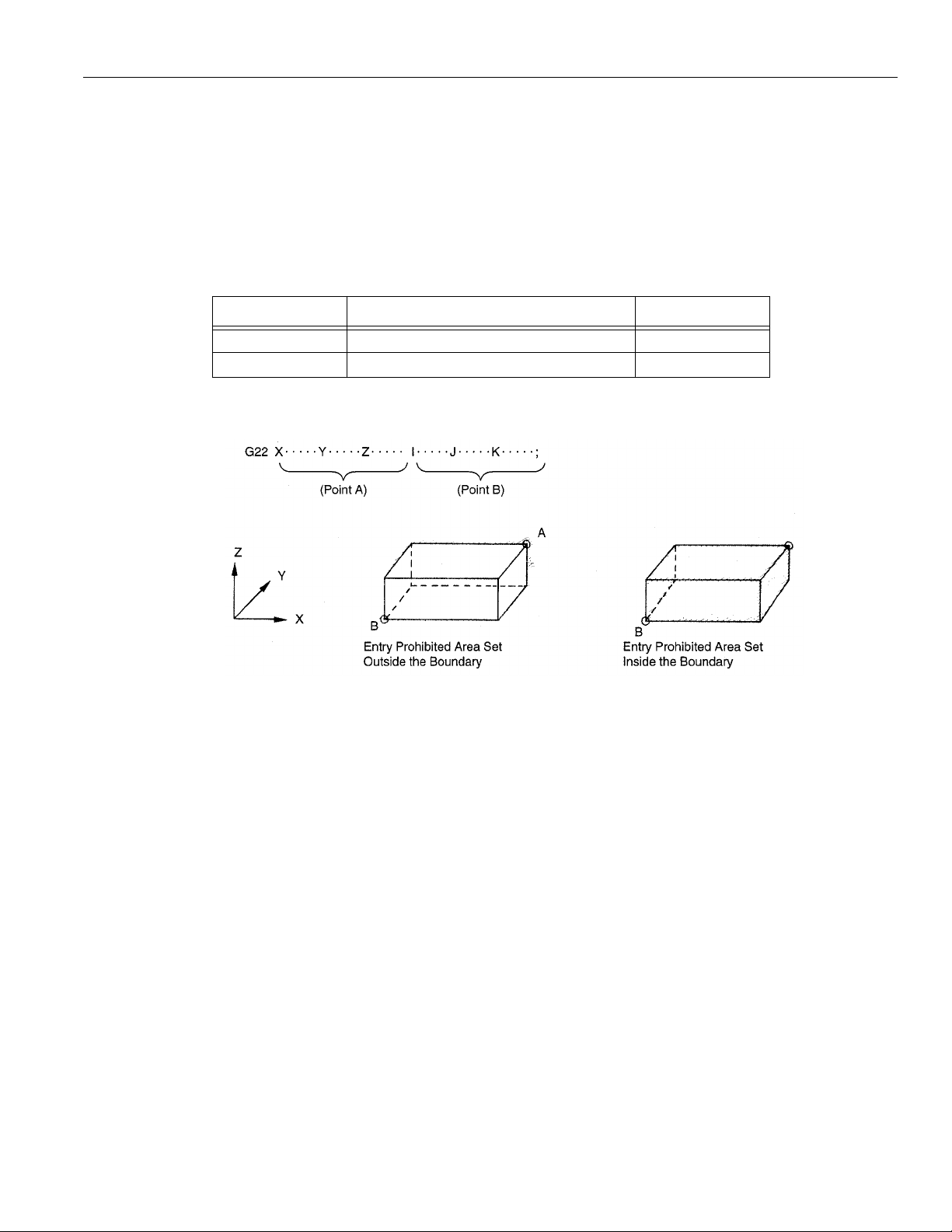
(2) Stored Stroke Limit B, C (G22, G23) *
The area either outside or in s id e the boundary set by par ameters or by the commands in a
program is established as the entry prohibited area. The boundary is set with the coordinate va lues in the m achine coordinate system. W h ether the entry prohibited area is esta blished outside or inside the boundary can be determined by the setting for a par ameter.
The function is made valid upon completion of the reference point return after turning ON
the power.
Table 1.2.3.1: G Code Used to Turn ON/OFF the Stored Stroke Limit B Function
G CODE FUNCTION GROUP
G22 Turning ON the stored stroke limit B 04
G23
Turning OFF the stored stroke limit B
04
FIGURE 1.2.3.2: Stored Stroke Limit B Function
• In addition to the stored stroke limit s A and B, stor ed stroke limit C can be added.
• With the stored stroke limit C, set the boundary of the area and inside or outside the
boundary by parameters.
• Accord in g to the setting for the parameter or the input signal , one of the stor e d str o ke
limit C (third to fifth prohibited area ) ca n be ma de valid.
• For details of the stored stroke limit B, C, refer to 4.2. 3 “Stored Stroke Limit B and C
(G22, G23)” in the PROGRAMMING MANUAL.
1 - 11
Page 23

YASNAC PCNC Operating Manual Chapter 1: Outline of YA SNAC System
1.2.4 Interlock Inputs
The interlock input is the signal used to disable axis mov em ent, and is provided for each axis.
• When an axis is interlocked during movement, it is stopped after deceleration.
• When the interlock is re leased, the axis con tinues mo ving to co mplete th e remainin g com-
mands. Upon com ple tion of the commands, the program advances to the next block.
• For simu ltaneous two or three axis interpolation commands, interpolation operation is disabled if one of the s e two or three axis is int erlocked.
Fig. 1.6 Interlock Inputs
1 - 12
Page 24

YASNAC PCNC Operating Manual Chapter 2: Basic Operation of YASNAC PCNC
2
PCNC System Outline
Chapter 2 describes various operations including power ON procedure,
manual operation and automat ic oper ation.
2.1 Gen eral Operation Flow . . . . . . . . . . . . . . . . . . . . . . . . . . . . . . . . . . . . . . . . . . . . 2-4
2.2 Insection before Turning the Power ON. . . . . . . . . . . . . . . . . . . . . . . . . . . . . . . . 2-5
2.2.1 Inspection of the PCNC unit. . . . . . . . . . . . . . . . . . . . . . . . . . . . . . . . . . . 2-6
2.2.2 Prepartion before Turning the Power ON. . . . . . . . . . . . . . . . . . . . . . . . . 2-7
2.3 Turning the Power ON/OFF and Inspection after Power ON/OFF . . . . . . . . . . . 2-8
2.3.1 Procedure for Turning the Power ON. . . . . . . . . . . . . . . . . . . . . . . . . . . . 2-8
2.3.2 Checking the Motors for Abnormalities . . . . . . . . . . . . . . . . . . . . . . . . . . 2-9
2.3.3 Procedure for Turning the Power OFF . . . . . . . . . . . . . . . . . . . . . . . . . . . 2-9
2.3.4 Inspection of the Battery. . . . . . . . . . . . . . . . . . . . . . . . . . . . . . . . . . . . . . 2-10
2 - 1
Page 25

YASNAC PCNC Operating Manual Chapter 2: Basic Operation of YASNAC PCNC
2.4 Manual Operation (1) . . . . . . . . . . . . . . . . . . . . . . . . . . . . . . . . . . . . . . . . . . . . . . .2-12
2.4.1 Manual Rapid Traverse (RAPID). . . . . . . . . . . . . . . . . . . . . . . . . . . . . . . .2-12
2.4.2 Jog Feed (JOG). . . . . . . . . . . . . . . . . . . . . . . . . . . . . . . . . . . . . . . . . . . . . .2-13
2.4.3 Step Feed (STEP) . . . . . . . . . . . . . . . . . . . . . . . . . . . . . . . . . . . . . . . . . . . .2-13
2.4.4 Handle Feed (HANDLE)* . . . . . . . . . . . . . . . . . . . . . . . . . . . . . . . . . . . . .2-13
2.5 Manual Operation (1) . . . . . . . . . . . . . . . . . . . . . . . . . . . . . . . . . . . . . . . . . . . . . . .2-13
2.5.1 Simultaneous 2- o r 3-axis Handle Feed* . . . . . . . . . . . . . . . . . . . . . . . . . .2-15
2.5.2 Manual Reference Point Return . . . . . . . . . . . . . . . . . . . . . . . . . . . . . . . . .2-16
2.5.3 Manual Reference Point Return to the Second Reference Point . . . . . . . .2-18
2.5.4 1-line MDI . . . . . . . . . . . . . . . . . . . . . . . . . . . . . . . . . . . . . . . . . . . . . . . . .2-19
2.6 Automatic Operation (1). . . . . . . . . . . . . . . . . . . . . . . . . . . . . . . . . . . . . . . . . . . . .2-20
2.6.1 Preparation of Automatic Operation. . . . . . . . . . . . . . . . . . . . . . . . . . . . . .2-20
2.6.2 Memory Operation . . . . . . . . . . . . . . . . . . . . . . . . . . . . . . . . . . . . . . . . . . .2-22
2.6.3 MDI Operation . . . . . . . . . . . . . . . . . . . . . . . . . . . . . . . . . . . . . . . . . . . . . .2-23
2.6.4 Feed Hold . . . . . . . . . . . . . . . . . . . . . . . . . . . . . . . . . . . . . . . . . . . . . . . . . .2-23
2.6.5 Override . . . . . . . . . . . . . . . . . . . . . . . . . . . . . . . . . . . . . . . . . . . . . . . . . . .2-24
2.7 Automatic Operation (2). . . . . . . . . . . . . . . . . . . . . . . . . . . . . . . . . . . . . . . . . . . . .2-24
2.7.1 Optional Stop . . . . . . . . . . . . . . . . . . . . . . . . . . . . . . . . . . . . . . . . . . . . . . .2-24
2.7.2 Optional Block Skip . . . . . . . . . . . . . . . . . . . . . . . . . . . . . . . . . . . . . . . . . .2-24
2.7.3 Dry Run. . . . . . . . . . . . . . . . . . . . . . . . . . . . . . . . . . . . . . . . . . . . . . . . . . . .2-26
2.7.4 Display Lock and Machine Lock . . . . . . . . . . . . . . . . . . . . . . . . . . . . . . . .2-26
2.7.5 Auxiliary Function Lock. . . . . . . . . . . . . . . . . . . . . . . . . . . . . . . . . . . . . . .2-27
2.7.6 Z-axis Command Neglect. . . . . . . . . . . . . . . . . . . . . . . . . . . . . . . . . . . . . .2-27
2.7.7 4th-axis Command Neglect . . . . . . . . . . . . . . . . . . . . . . . . . . . . . . . . . . . .2-27
2.7.8 5th-axis Command Neglect . . . . . . . . . . . . . . . . . . . . . . . . . . . . . . . . . . . .2-28
2 - 2
Page 26

YASNAC PCNC Operating Manual Chapter 2: Basic Operation of YASNAC PCNC
2.8 OPERATION INTERVENTION (during automatic operation). . . . . . . . . . . . . . .2-29
2.8.1 Manual Operation Intervention during automatic ope ra ti on . . . . . . . . . . .2-29
2.8.2 MDI Operation Intervention during automatic operation. . . . . . . . . . . . . .2-30
2.8.3 Automatic Handle Mode Offset . . . . . . . . . . . . . . . . . . . . . . . . . . . . . . . . .2-30
2.8.4 Manual Absolute. . . . . . . . . . . . . . . . . . . . . . . . . . . . . . . . . . . . . . . . . . . . .2-32
2.9 AUTOMATIC OPERATIONS AT ENHANCED LEVEL. . . . . . . . . . . . . . . . . . .2-34
2.9.1 Tool Length Measurement* . . . . . . . . . . . . . . . . . . . . . . . . . . . . . . . . . . . .2-34
2.9.2 Return to the Operation Interrupted Point* . . . . . . . . . . . . . . . . . . . . . . . .2-37
2.9.3 Manual Centering Operation* . . . . . . . . . . . . . . . . . . . . . . . . . . . . . . . . . .2-37
2.9.4 Program Restart . . . . . . . . . . . . . . . . . . . . . . . . . . . . . . . . . . . . . . . . . . . . .2-38
2.9.5 Playback Function. . . . . . . . . . . . . . . . . . . . . . . . . . . . . . . . . . . . . . . . . . . .2-44
2 - 3
Page 27

YASNAC PCNC Operating Manual Chapter 2: Basic Operation of YASNAC PCNC
2.1 General Operation Flow
The operatio n proc edure usually followed for daily operation is i ndi cated in Figure 2.1. This
chapter explains these operation items.
Setting Part Program
Loading NC program from PC
by Ethernet or from touch
screen and executing the
Program numbers
FIGURE 2.1.1: Operation Proc edure
2 - 4
Page 28

YASNAC PCNC Operating Manual Chapter 2: Basic Operation of YASNAC PCNC
2.2 Inspection Before Turning the Power ON
Before turning the power ON for YASN AC PCN C, it is necessary to carry out inspe c ti on t o
Ensure safety. If the power is turned ON while the system has trouble, it could cause malfunctioning of the system itself and create a hazards conditions for the operations. Make sure to carryout daily inspection bef ore turni n g the power ON.
WARNING!
• Always turn all power OFF (including the primary power supply) before carrying out daily
inspection.
Performing the inspection with the power ON may lead to electric shock.
• Wait 5 minutes after turni ng the power (including the primary power supply ) OFF befo re
removing or replacing any unit or part.
Failure to observe this warning could lead to electric shock and equipment failure.
• Do no t touch any unit, terminals, e tc., while the powe r is ON.
Failure to observe this warning could lead to electric shock or device malfunction.
• Immediately after switching the power OFF, the product retains some electric charge. Do not
touch any parts (which are live when the power is ON) for 5 mi nutes after switching the po w er
OFF.
Failure to observe this warning could lead to electric shock or device malfunction.
• Do not damage cables, subject them to exc essive stress, or pinch them.
Excessive load on cables may cause electric shock.
• When the equi pment is po w ered ON, never tou ch its rota ting parts.
Failure to observe this warning could result in personal injury.
• Ne ver modify the produ ct.
Failure to observe this warning could result in electric shock, fire, or product failure.
2 - 5
Page 29

YASNAC PCNC Operating Manual Chapter 2: Basic Operation of YASNAC PCNC
CAUTION!
• To prevent personnel other than those invo lv ed in maintenance and in spe ct io n w ork from
turning the power ON whi l e mai nt ena nc e and i nspe ct io n is in progress, place signs stating
“DO NOT TURN THE POWER ON” or words to that effect at the primary power
supplies of related cont rol pan el s and othe r re le va nt l oca t ion s.
Failure to observe this caution could lead to electric shock.
• Electronic devices such as CMO S ICs are used on the control boards. If you touch the IC’s
with your bare fingers, static electrical charge in your body could destroy these IC’s, care must
be taken when handling these devices. Before handling these devices for maintenance purposes,
first discharge the static electricity in your body by touching a gro unded metal device.
Failure to observe this caution could lead to personal injury and product failure.
• Do not install or remove boards, wiring, connectors, etc., while the power is ON.
Failure to observe this caution could lead to electric shock, product failure, and malfunction.
• Do not let foreign matter such as ele ct ric a l wire scrap enter the unit .
Failure to observe this caution could result in fire, product failure or malfunction.
• Be sure to check the follow in g points after comple t ing maintenance and inspection work:
• Check that al l fastening bolts are tightened.
• Check that no tools or other objects have been left inside the control panel.
• Check that the control panel door is closed properly.
Failure to carry out these checks could lead to electric shock, injuries, fire, and malfunction.
• Never attem pt to disa ssemble the NC unit modify units/dev ices inside the PC N C unit.
Failure to observe this caution could lead to fire, product failure and malfunction.
• Do not change the se t values of the devices, variab le resistors, et c., in the control panel.
Failure to observe this caution could lead to fire, product failure, and malfunction.
2.2.1 Inspection of the NC Unit
In this subsection, the items to be inspected before turning ON the power are indicated for the
standard PCNC box supplied by Yaskawa. For the machine tool’s control box, refer to the
machine tool man ua ls.
(1) Inspecting the Machine Cabinet Doors
Make sure that the doors are secu rely closed before turning th e power ON.
The PCNC CPU ra ck is not protected against oil mists or ot he r ai rborne foreign matt er.
The door of the machine cabinet doors must always be kept closed before powering ON.
2 - 6
Page 30

YASNAC PCNC Operating Manual Chapter 2: Basic Operation of YASNAC PCNC
(2) Inspecting the Shielding Parts in the Machine Cabinet
Inspect the shielding parts in the Machine Cabin et eve ry m onth for gaps and/or damag e.
Open the doors and check the packings installed around the door for dama ge.
ó
Inspect the inside of the Machine Cabinet for abnormal contamination. If the inside is
abnormally dirty, clean it immediately after loc a ti ng the cause of contamination.
ì
Lock the doors secure ly a nd in spect the doors to make sure that th ere are no gaps.
By carrying out th e inspection procedures indicated above at regular int erv als, the
YASNAC PCNC can pe rform efficiently for a long time .
2.2.2 Preparation before Turning the Power ON
Before turning the power ON, confirm the following con dit io ns:
• Make sure that the front side of the PCNC unit is closed. If the door is open or if there is a
gap between the door and the box panels, securely close and loc k t he door.
• Carry out the inspection for the machine an d machine related controllers according to the
instructions in t h e machine to ol manuals.
2 - 7
Page 31

YASNAC PCNC Operating Manual Chapter 2: Basic Operation of YASNAC PCNC
2.3 Turning the Power ON and Inspecting After Power ON
In this section, the procedure to be used for turning the power ON is explained. Inspect io n tha t
must be conducted after turning the power ON is als o descr ib ed.
WARNING!
• Be sure to turn the power OFF before replacing the battery.
Failure to observe this warning could lead to electric shock and product failure.
CAUTION!
• Replace fuses and bat teries with the recommend ed products.
Failure to observe this caution could result in fire or product failure.
• Use the product wi th the “System Number Switch” of the CPU set to “0”.
Using while set to another number could lead to malfunction.
• Wait at least 2 seconds afte r tu rning th e p ower OFF before turning it ON again.
Failure to observe this caution could lead to malfunction.
2.3.1 Proc ed u re for Tur n in g the Power O N
Turn the power ON in the following sequence.
Make sure that the power supplied to the PCNC unit is from an external power source.
ó
Press the POWER ON butt on on the N C ope ra ti on pa ne l. Con trol power is turned
ON and the co ol ing fan starts rotating .
ì
Make sure that air is flo wing out at the upper part on the side of the N C uni t.
• In approximately 20 seconds, the con tro l is re ady for turning ON the servo power
(alarm code 3000).
ö
Press the POWER ON button again - one time.
• The ser vo power is turned ON. When the machine is ready fo r op eration, th e NC
enters th e re ady state.
• When the power is correctly turned ON to th e N C unit, the NRD (NC ready) signal
is output.
• When the power is turned ON at the machine side in response to the NRD signal, the
MRD (machine ready) signal will be returned to the NC. The READY lamp goes on
when the MRD signal is r eturned. Note that a READY lamp is not used with some
types of machines.
2 - 8
Page 32

YASNAC PCNC Operating Manual Chapter 2: Basic Operation of YASNAC PCNC
• When th e NC unit enters the ready state, the alarm message (displayed on the screen)
will go off.
ú
If the NC unit fails to enter the ready state, locate the cause by referring to Section 7.2,
“ALARM DISPLAY JOB”, and take appropriate steps. For turning the power O N,
there ar e items that must be inspected at th e machine side in addition to t he NC unit
related items. For the former items, refer to the machine t o ol manuals .
5
PCNC Boots MMI screens
FIGURE 2.3.1.1: Power O N Seque nce
2.3.2 Checki n g the Mot ors for Abnormalities
Check the operation of the motors runni ng. If abnormal vibrat ion or noise occurs, turn the pow er
OFF and contact th e m ai ntenance personnel.
2.3.3 Proc edu re for Tur n in g Power OFF
Turn the power OFF in the following sequenc e:
Make sure that the CYCLE START lamp on the mach ine operation panel is OFF
with the machine stopped.
ó
Make sure that there is no al arm message displayed on t he CRT screen. If an alarm
message is displayed, locat e the c ause by referring to Chapter 4, “MAI NTENAN-
ACE” and take appropriate measures to clear it.
ì
Carry out necessary STEPS for turn in g the power OFF at the machine side. For
details , refer to t he machine to ol manuals.
ö
Press the EMERGENCY STOP button on the machine operation pa ne l t o tur n the
servo power OFF.Press SHUTDOWN button to clo se all opened window s of PCNC.
ú
When the safe SHUTDOWN mess age is displayed on CRT ,Press the POWER OFF
button on the NC operation panel to shut off the power to PCNC.
2 - 9
Page 33

YASNAC PCNC Operating Manual Chapter 2: Basic Operation of YASNAC PCNC
÷
Turn the power supply to the NC OFF by turn in g O FF a circuit breaker, etc.
PCNC
PCNC Display
Shut Down button
Shut Down of PC Side
Closing Windows NT
Safe to Turn Off Windows NT
FIGURE 2.3.3.1: Power OFF Sequen ce
2.3.4 Inspection of the Battery
After turning the power ON, if th er e is a battery alarm , a broken battery icon will be displa ye d,
or a solid battery is displayed to indicate everyt hi ng is normal. After two minute s this norm al
battery indicator will disappear. When battery alarm is disp la ye d by red battery icon, the bat tery
must be replaced imm e diately. Standard bat teries cannot be used. Fo r a re pla c em ent of battery,
contact your Yaskawa represent at iv e for Battery type: ER6VC3, Parts code: BA510
(1) Checking the Battery Which Needs Replacing
Follow the procedure indicated below to determine whether or not battery must be replaced.
Press the POWER OFF button.
ó
If a door interlock switch is installed, place the door interlock key in the OFF position.
This makes a power O N con dit io n possi ble with the door opened.
ì
Open the door so that the front part of the PCNC unit i s visi ble .
ö
Press the POWER ON button again - once.
2 - 10
Page 34

YASNAC PCNC Operating Manual Chapter 2: Basic Operation of YASNAC PCNC
ú
Check th e r ed color LE D on the JANC D-JFC10 bo ar d. If it is lit , the batter y must be
replaced.
I/O module power out put
verification LED
I/O module power output
verification LED
Battery power supply
connector (C N0 6)
Battery
Fuse (HM03, 0.3A)(F1)
Fuse (5A) (F2)
(Behind Battery)
FIGURE 2.3.4.1: Location of the Battery on the PCNC board
2 - 11
Page 35

YASNAC PCNC Operating Manual Chapter 2: Basic Operation of YASNAC PCNC
2) Replacing the Ba tt ery
Replace the battery easily with the following procedure.
Turn the PCNC power OFF.
ó
Remove connec t o r of Ba tt ery.Then, remov e th e battery from the holder by desoldering.
ì
Fit the new battery in the holder and carefully solder RED(+) and BLACK (-) wires to
the Battery. Put the battery in its holder.Then pu t back batt er y connector, the connector may be inserted in either direction, it must be securely inserted, otherw ise , t he
power will not be suppli ed by the ba tt ery. (See Fig. 2.7.)
Connect Red wir e
( + )
B
A
T
T
E
R
Y
Connect Black wire ( - )
FIGURE 2.3.4.2: Connecting the Battery Connector
ö
Turn the power ON.
ú
Make sure that “BAT” is not blinking on the CRT screen, and that the red color LED
in the board is OFF.
1. If the red color LED remains lit after rep lacin g the batter y , th e connecto r might be inserted
incorrectly or the battery might be faulty.
2. Power OFF operati on i s all owed a few seconds after turni ng t he power ON.
3. After turning the power OFF, replace the battery quickly. If the PCNC unit is left with the
battery removed, the data stored in the memory could be lost.
2 - 12
Page 36

YASNAC PCNC Operating Manual Chapter 2: Basic Operation of YASNAC PCNC
2.4 Manual Operation (1)
This section desc ri be s ge ne rally the manual ope ration. To move an axis manually, select the
operation mode of RAPID, JOG, STEP, or HANDLE with the MODE SELECT switch on
the machine operatio n panel.
2.4.1 Manual Rapid Traverse (RAPID)
An axis can be move d at a rapid traverse rate. Follow the procedure in dic ated below.
Select the rapid mode by placing the MOD E SE LE CT switch on the machine
operation pane l i n the RAPID po s ition.
ó
Select the feedrat e to be use d for a xis feed operation by the RAPID TRAVERSE and
RATE OVERRIDE sw itch on the mac h i n e operation p anel.
• Override setting is possible in four steps of 100%, 50%, 25%, and F
. The feedrate
0
corresponding to the settin g at 100%, 50%, and 25% is set for parameters pm2801
to pm2805. For the setting at F
• Optionally, F
the switch setting at F
ì
On the machine operation panel, pres s th e JOG button that corresp onds to the axis
and F2 positions are select able. Feedrate to be selected according to
1
and F2 is set for parameters pm 2448 and pm2449.
1
, feedrate set for parameter pm2447 is used.
0
and the direction in w hi ch the axis should move. The axis moves at a rapid traverse
rate while the button is held pressed.
2 - 13
Page 37

YASNAC PCNC Operating Manual Chapter 2: Basic Operation of YASNAC PCNC
2.4.2 Jog Feed (JOG)
It is possible to move an axis in the jog feed mode. Follow the procedure indicated below.
Select the jog mode by placing the M ODE SELECT switch on the machine operati on
panel in the JOG position.
ó
Select the feedrate with the J OG FEEDRATE sw itch on the machine operation panel.
• Feedrate can be selected from 32 steps, with actua l fe edrates of individual settin g
positions set for paramete rs pm2 400 to pm2431. The actual number of steps and
feedrates sele ctable by the JOG FEE D RATE switch var y depend ing on the m achine
model. For details, refer to the ma nua l s pu bl ishe d by the machine tool buil de r.
ì
Press the JOG swit ch corresponding to the axis to be moved and the required axis
move direction.
ö
The axis moves at the selected feedrate while the JOG switch is held pressed.
2.4.3 Step Feed (STEP)
Manual step feed operation is possible. Follow the procedure indicated below.
Select the step mode by plac in g the MODE SELECT swit ch on the machin e oper atio n
panel in the STEP position.
ó
Select the feed distance per step with the MANUAL PULSE MULTIPLY switch on
the machine operatio n panel.
Metric system : 0.001, 0.01, 0.1, 1.0, 10.0 , 100 .0 mm (pe r step)
Inch system : 0.0001, 0.001, 0.01, 0.1, 1. 0, 10.0 inch (per step)
ì
Press the JOG swit ch corresponding to the axis to be moved and the required axis
move direction.
ö
Each time th e JOG switch is pressed, th e selected axis moves in the selected direction
by the set feed distance per step.
2.4.4 Handl e F ee d (HANDLE)*
When the NC is equipped with a manual pulse generator, pulse handle feed operation is possible.
Follow the procedure ind ic at e d bel ow.
Select the handle mode by placing th e MO D E SELECT switch on the ma chine operation panel in the HANDLE position.
ó
Select the axis to be moved by the HANDLE AXIS selection switch on the machine
operation panel .
ì
With the MANUAL PULSE MULTIPLY switch on the machine operation panel,
select the axis feed di stance per pulse (one division of the pulse handle).
2 - 14
Page 38

YASNAC PCNC Operating Manual Chapter 2: Basic Operation of YASNAC PCNC
Clockwise rota ti on: I n the positive direction
Counterclockwise directi on: In the negative direction
Metric system: 0.001, 0.01, 0. 1 mm (p er division)
Inch system: 0.0001 , 0.001 , 0.01 inch (per division)
ö
Turn th e pulse handle. The axis moves in the positive or nega tive directio n acco r d ing
to the direction in which the pulse handle is turned.
2 - 15
Page 39

YASNAC PCNC Operating Manual Chapter 2: Basic Operation of YASNAC PCNC
2.5 Manual Operation (2)
This section descri bes manual operation s car rie d out in da i ly production using the manual
operation func tions explained in 2.4 “MANUAL OPERATION (1)“.
2.5.1 Simultaneous 2 or 3-axis Handle Feed *
By installing the pulse handle for the individual axis, it is possible to move up to three axis among
the X-, Y-, Z-, α-, and β-axis simulta neously. Follow the proce dure indicated belo w.
FIGURE 2.5.1.1: Simultaneous 2 or 3-axis Pulse Handle Feed
Select the handle mode by pl acing the M O D E SELECT switch on th e machin e
operation panel in the HANDLE positi on .
ó
Select the axis feed distance per graduation of the pulse handle with the MANUAL
PULSE MULTIPLY switch on the machine operation panel. This switch is used in
common for the three pulse handles.
ì
Turn the pulse handle. The selected axis is moved in the positive or negative direction
according to the handle tu r ning direction.
2 - 16
Page 40

YASNAC PCNC Operating Manual Chapter 2: Basic Operation of YASNAC PCNC
2.5.2 Manual Refe rence P oint Return
Axes can be returne d to the refe re nce point in manual op eration. Follow the proc edure indicated
below.
Select the rapid or jog m ode by placing the MODE SELECT switch on the m ac hine
operation pane l i n the RAPID or JOG posit ion.
ó
Move an axis manually (manual rapid traverse or jog feed) to a posi tion away from
the reference point (within the reference point return enabled area).When an axis is
located in range A in Fig. 2.9, reference point return can be executed correctly.
ì
Turn ON the REFERENCE POINT RETU RN sw itch.
ö
Keep the JOG switch pressed corresponding to the axis returning to the reference point
and in the return direction. When the JOG switch is held pressed, the corresponding
axis starts moving in t h e s ame manner as ordinary m anual axis feed o peration.When
the axis reaches the deceleration point, feedrate is decelerated to a low feedrate and
the axis s tops autom atically at the reference point.
ú
Upon comple ti on of the reference po int ret urn, the REFERENCE POINT lamp of
that axis lights.
FIGURE 2.5. 2.1: Manual Reference Point Return
t
Refere nc e Point is a specific p osition in th e machine coordinate system . I t is also ca lled the
machine ze ro poi nt or the machine refe rence point.
1. Once the refere nce point return is compl eted, point C indicated in Fig. 2. 9 is stor ed to the
NC. Therefore, if reference point ret urn i s att empted while an axis is in are a B, an error
occurs. In this case, the axis should first be returned to area A and then the reference point
return should be executed.
2. The axis for whi ch t he refe rence point return has been c om pleted can be moved in
2 - 17
Page 41

YASNAC PCNC Operating Manual Chapter 2: Basic Operation of YASNAC PCNC
the reference point re tu rn direction manuall y onl y if t he re ference point return swit ch
is turne d OFF.
3. If command s h av e be en read to the buffer area du ring automatic op eration, manual
reference point return must not be executed. If manual return operation is executed,
the data in the buffer area is cleared.
1. Immediately after the power is turn e d ON, the axi s star t man ual or automatic reference
point return operation independent of the present axis position. However, reference point
return cannot be executed correctly if the axis is located in area B. In this case, the axis
must be returned to a rea A before executing reference point return.
2. If the MODE SELECT switch setting is changed while an axis is moving automatically to
the reference point, an alarm (alarm 2141 to 2145 reference point return interruption error)
occurs.
3. Reference poi nt return cannot be exec ut ed when the MACHI N E LOCK switch is ON.
4. With a rota r y axis, it is possible to execute autom atic reference point return as with a
linear axis.With a rotary axis, if it has been mov ed by more than ± 360.000° from the
reference point established first, reference point return is executed to the closest reference
point in the preset di rection of referenc e point return.
The illustration below shows how the reference point return is executed from points A and
B. (The reference poi nt ret urn direction is determ in ed by the setting for pm4002 D3 and
D4.)
5. Once the reference point return is completed, second and later reference point return is
executed at a high-speed mod e. This is call ed “high-speed reference point return”. However, if the setting is so made to execute the reference point return at a low speed (pm4003
D6 = 1), second and later refer ence point return is executed at a low sp eed.
2 - 18
Page 42

YASNAC PCNC Operating Manual Chapter 2: Basic Operation of YASNAC PCNC
2.5.3 Manual Reference Point Return to the Second Reference P oint *
The axis are automatically positioned at the second reference point. This operation allows positioning at the second reference point independent of the present axis position, whether it is in
the negative side or positive side from the second reference position. Follow the procedure indicated be low.
Select the jog or rap id mode by placing the MODE SE LE CT switch in the JOG or
RAPID position.
ó
Turn ON the ZRN2 (second zero poin t return request) switch on the m ac hi ne operation pa nel.
ì
Keep the JOG swit ch co rre sp ondin g to the ax i s and d ire ct ion o f r efer enc e poi nt r et urn.
The corresponding axis is positioned at the second zero point at the jog feedrate or
rapid traverse rate ac cording to the selecte d m ode.
• If the ZRN2 switch is turned OFF while an axis is moving to the second reference
point, the axis stops moving . To restart the second reference poi nt re tu rn ope ration,
turn ON the ZRN2 swi tch and turn OFF the JOG switch having been pressed once,
then press it once again.
• If the JOG switch is pressed again to be turned OFF while the X-axis is moving to the
second zero point, the axis stops moving. In this case, press the JOG switch again to
turn it ON, and the X-axi s rest art s mo vi ng to the sec ond z ero point.With the Y- and
Z-axis, this is also app lied.
1. If the JOG switches of [+] an d [ –] are pressed at the same time, the corresponding axis
stops moving sin ce this ope r ation is ass umed to have turned O FF the JOG switch.
2. It is not allowed to use the first zero point return mode and the second reference point
return mode at the same tim e. If both input signals are ON at the sa me ti me, both of the
modes are invalid and nei ther jog nor rapid feed is exe cu te d. Thi s fea tu re is provided to
ensure safety.
3. If the NC is in either the machine lo ck s tate (includ ing the machine lock for individual
axis) or the Z-a x is command disregard stat e, the secon d zero point return operation cannot be executed. When a JOG switch is pressed under such a state, normal jog operation
is preformed.
4. With the axis for which seco nd zero point return ha s bee n completed, manu al axi s mov e
operation is allowed on ly a fte r th e Z RN2 (second reference point retu rn) swi tc h is tu rne d
OFF.
2 - 19
Page 43

YASNAC PCNC Operating Manual Chapter 2: Basic Operation of YASNAC PCNC
1. If the second zero point return input signal is turned ON in the state that the first zero point
return h as not bee n co mpleted , th e input is in v alid and the second r eference p oint return
mode cannot be set .
2. In the second reference point return mode, inpu t fro m t he JOG switch [-X] ([-Y], [-Z]) is
valid. If the mode is cha nged, the ZRN2 switch is assumed to have been turned OFF.
2.5.4 1-line M D I
During the execution of manual operation, it is possible to execute one block of a part program by
directly entering it to the CRT screen. For this type of operation, a maximum of 40 characters can
be written and the function codes that are allowed are M, S, T, F, and E codes.
However, M00, M01, M02, M30, M90 to M99, an d M190 to M199 cannot be specified. A n
offset command with a T co mman d is also disregarded . With the system that car ries out set-up by
using a T command, a T command must not be specified for this 1-line MDI operation.
Follow the procedure ind ic at e d bel ow.
Select the manual mode with the MODE SELECT switch on the machine operation
panel. 1-line MDI op era ti on is not possible in the automa t ic or edit m ode.
ó
Enter the program from the operation panel.
ì
Press the CYCLE START switch on the machine operation panel, and the entered
program is executed. When the execution of the program is completed, the pr ogram
displayed in the key ent ry di spl ay are a is c leare d.
• If the mode is chan ge d w h i le the program is executed (waiting for FIN), the FIN is
not returned forcibly and the NC rem ains in the st ate waiting for the in p ut of FIN.
2 - 20
Page 44

YASNAC PCNC Operating Manual Chapter 2: Basic Operation of YASNAC PCNC
2.6 Automatic Operation (1)
This section descri be s basic in formation necessary for pe rforming automatic operation.
CAUTION!
• Before carrying out a cutting operation with a new program, confirm safety by performing the
single block operat ion and dry run operation.
If this pr e ope ratio nal chec k is not perfor med, unexp ected o perati on may result due to mis-setting of the amo unt of
offset, leading to tool damage due to interference. The resulting interference may cause injury to personnel.
• Strictly observe the caut i o ns in the user’s manual when using programming func tions.
Ignoring these cautions could lead to accidents involving injuries to personnel and malfunctions.
2.6.1 Prep aration of Automatic Operation
After turning the power ON, the ax is mu st be positioned at the start point defined in a program
before starting automatic operation. Set the coordinate system to be used for machining either
manually or by specifyi ng appropriate comma nds in a program. Several examp le s are giv en
below to explain how the coordinate system should be set. For details, refer t o the machine tool
manuals.
(1) Setting the Coordinate System
The origin of the c oordinate system to be use d for e xecuting the comma nds should be set.
(a) When G92 is not specified in the program
The coordinate syst em for which the origin is set at othe r th an the reference point f or th e
program not containing the coordinat e system setting comman d (G 92) is called a coordinate system for machining. The procedure for setting a coordinate system for machining is
indicated below.
Return t h e axis to the r eference point by fo llowing th e manual re f erence point return
procedure (see 2.4. 2).
ó
Select the MDI mode by pl ac ing the MODE SELECT swit ch on the machine opera tion panel in the MDI position .
2 - 21
Page 45

YASNAC PCNC Operating Manual Chapter 2: Basic Operation of YASNAC PCNC
ì
Write the program for setting the coordinate system.
For example,
G92X • • • Y • • • Z • • • ;
FIGURE 2.6.1. 1: Coordinate Sy stem for Machining
ö
Execute the progr am by pressing the CYCLE START switch on the mach ine ope ration pa nel.
(b) When G92 is specified in the program, return the axis to the reference point by manual ref-
erence point return operation.
Example of Pr ogramming
EOR;
N1 G92X • • • Y • • • Z • • • ;
(c) When G28 (automat i c re ference program poi nt return) and G92 are sp ec if ie d in the
program, move the axis manually to a position (in the area where reference point return
operation is allowed) aw ay from the refe rence point.
Example of Pr ogramming
EOR;
N1 G28 • • • Y • • • Z • • • ;
N2 G92X • • • YO • • • Z • • • ;
2 - 22
Page 46

YASNAC PCNC Operating Manual Chapter 2: Basic Operation of YASNAC PCNC
(2) Start Lock
Keep the machine in the start lock state until it is confirmed that machine operation is
permitted. Follow the procedure indicated below.
Before starting machine operation, turn the START LOCK switch on the machine
operation panel O N .
ó
After safety is conf ir med , tu r n the S TART LOCK switch OFF.
2.6.2 Memory Operati on
Memory mode operation is used to carry out automatic operation by using programs stored in the
PCNC memory. Follow the procedure indi cated below.
Make sure t h at the alarm icon on the PCNC MMI is green . If the alarm icon is red,
touch the alarm icon button and locate the cause by referring to 9.1.4, “Cause of Al arm
and Corrective Action” and take appropriate measures to clear it.
ó
Check the tool offset amounts and correct the m if necessary, then position the axis at
the start point. For details of tool offset, refer to 5.3, “TOOL DATA CONTROL
JOB”.
ì
Carry out necessary settings with the switches on the machine operation panel.
• Selec t the memory mode by placing the MODE SELECT switch in the MEM pos ition.
• Set the SINGLE-BLOCK switc h O N or OF F. To execute the program blo ck -by-
block, set it ON.
• Set the rapid tra v e r s e rate with th e RA P ID TRAVERS E RATE OV ERRIDE swi tc h .
• Set the MANUAL ABSOLUTE switch ON or OFF. Set the switch ON to return the
tool by manual operation interven t ion to the previously located position .
• Set the OPTIONAL BLOCK SKIP switch ON or OFF . Set the switch ON to disregard
the blocks that include the “/” (slash) code.
• Set the OPTIONAL STOP switch ON or OFF. To execute the optional stop function
(M01), set the switch ON.
• Set the DRY RUN switch. ON or OFF. Set the switch ON when checking the
program.
• With the FEEDRATE OVERRIDE and JOG FEEDRATE switches, set the feedrate.
ö
Press the RESET button on the PCNC MMI operation panel. The program is rewound
to the beginning.
ú
Press the CYCLE START switch on the machine operation panel to start automatic
operation.
÷
To suspend operation temporarily, press the FEED HOLD switch on the machine
operation panel .
2 - 23
Page 47

YASNAC PCNC Operating Manual Chapter 2: Basic Operation of YASNAC PCNC
1. In case of emergency, press the EMERGENCY STOP butt on on the machine opera tion
panel to stop th e machine immediately.
2. It is possible to start a program half way in the memory mode operation. Locate the cursor
at the required start bl oc k by using the Run This bu tton, and press the CYCLE START
button. For this operation, however, the modal G codes must be set before starting the program.
3. In the memory mode , add ress search must always be execu ted by spe ci fyi ng “address +
nemeral”.
2.6.3 MDI Operation
Automatic operation is possible by inputting a program in the MDI mode. Follow the procedure
indicated below.
Select the MDI mode with the MODE SELECT switch on the machin e operation
panel.
ó
ì
2.6.4 Feed Hold
The feed hold function suspends automatic operation temporarily. Follow the procedure indicated
below.
ó
1. If the execution of a drilling canned cyc le is sto ppe d halfway due to the sing le blo ck
function, the FEED HOLD lamp auto matically goes ON to indicate that the operation
is suspended during the execution of a dr illi ng canned cycle.
Enter the block of co mmands from the keyboard. For details of program entry
operation in the MDI mode, refer to 6.2, “MDI OPERATION JOB”.
Press the CYC LE S TART switch on the machine ope ration panel and the executio n
of the entered pr ogr am is star ted.
When the F EED HOLD s witch on th e machine operation panel is pressed while an
axis is moving, it stops after deceleration. The CYCLE START lamp on the machine
operation panel goes OFF and the FEED HOLD lamp lights.
After the completion of axis movement, the indicating lamp goes OFF.
2. The setting of the FEED HOLD swit ch is disregarded while a ta pping cycle is executed
in the G84 mode.
3. If the FEEL HOLD sw it ch is turned ON w hile M, S, T, or B* function not associate d to
be completed although the FEED HOLD lamp lights immediately. After the completion
2 - 24
Page 48

YASNAC PCNC Operating Manual Chapter 2: Basic Operation of YASNAC PCNC
of the function, the FEED H O L D la m p goe s OFF and operation stops.
2.6.5 Override
The following providess a general descrip ti on of t he override function. For det ai ls of override,
refer to the machine tool manuals.
(1) Feedrate Override
In the automatic mode (TAPE, MEM, MDI), feedrate specified by an F code can be over-
ridden in 21 steps in the ra nge from 0 to 200% in incr em ents of 10%, using the
FEEDRATE OVERRIDE switch on the machine operation panel. During the execution of
a tapping cycle (G74, G84), the setting is disregarded an d the tapping cycle is executed in
the feedrate specified by the program. If the OVE RRIDE CANCEL switch is O N, the
setting of the FEED RATE OVERRIDE switch is disregarded and the axis are moved at
the feedrate specified by the F codes in a program.
Table 2.6.5. 1: Feedrate Override Steps
STEP % STEP %
0011110
1 10 12 120
2 20 13 130
3 30 14 140
4 40 15 150
5 50 16 160
6 60 17 170
7 70 18 180
8 80 19 190
9 90 20 200
10 100 - -
Optionally, feedrate overrid e ra nge can be expanded to 0 to 5 40% (32 steps). In this case,
override incre m ents are 10% in the range from 0 to 200%, 20% in the range from 220 to
300%, and 40% in th e range from 340 to 540%.
2 - 25
Page 49

YASNAC PCNC Operating Manual Chapter 2: Basic Operation of YASNAC PCNC
2.7 Automatic Operation (2)
This sectio n describes the switches used for automatic operation.
2.7.1 Optional Stop
The OPTIONAL STOP switch is used to select whether or not the M01 (optiona l sto p ) comman d
should be executed in the automat ic mode (MEM, M D I).
(1) OPTIONAL STOP Switch ON
When the OPTIONAL STOP switch is ON, the machine stops operating with the CYCLE
START lamp on the mach ine operatio n pane l lit after the execution of the block that
includes M01. Th e CYCLE START lamp goes OFF if the FIN signal is returned. The
operatio n r es tarts when the CYCLE START switch is pr es s ed.
(2) OPTIONAL STOP Switch OFF
The M01 command is disregarded. If the O PTIONAL STOP switch setting is changed
during the exec ut ion of an automatic operation, it is disregarded for the block presently
executed. Th e new setting becom es va li d from the block which is r ea d aft er the switch
setting has been changed.
2.7.2 Optional Block Skip
The OPTIONAL BLOCK SKIP sw it ch i s used to set whether or not the dat a in the block which
includes the “/” (slash) code should be disregarded in automatic operation. Note that if the switch
setting is changed during operation, the new setting is not valid for the blocks having been read to
the buffer area.
(1) OPTIONAL BLOCK SKIP Switch ON
When the OPTIONAL BLOCK SKIP switch is ON, the commands specified after the “/”
(slash) code are disregarded (up to the end of the block). For the blocks in which the “/”
code is specified, the commands specified preceding the “/” code are execut ed.
(2) OPTIONAL BLOCK SKIP Switch OFF
The blocks whi ch include the “/” (slash) code are executed. If the OPT IONAL BLOCK
SKIP switch setting is changed during the execution of an automatic operation, it is
disregarded for the block presentl y executed and also for the bloc ks ha ving been read to
the buffer area. Th e new setting becomes valid from the block wh i ch i s rea d aft er the
switch setting has been changed.
2 - 26
Page 50

YASNAC PCNC Operating Manual Chapter 2: Basic Operation of YASNAC PCNC
1. Specification of “/” is equivalent to”/ l“.
2. When the opt io na l bl ock skip 13 function is selecte d, the sw it che s are provided corresponding to “/2” to “/9” individually and by using these switches, it is possible to turn ON
and OFF the block skip function for the individual designation of “/2” to “/9”.
2.7.3 Dry Run
When automatic mode operation (TAPE, MEM, MD1) is executed with the DRY RUN switch
set ON, feedrates specified in a program are disregarded and axis move commands are executed
at the fe ed rate set w ith the JOG FEEDR ATE sw itch. Sin ce the F cod e s p ecified i n a p r ogram is
displayed during the execution of a program, the program can be checked efficiently by using this
function.
Feedrate to be used in posit io ning (G00) can be selected from the rapid traverse rate or jo g feedrate according to the setting for parameter pm2000 D0 as indicated in T able 2.2.
Table 2.7.3. 1: R apid Traverse in Dry Run
Parameter pm2000 D0 G00 in Dry Run
“0” Rapid traverse rate “1” Jog feedrate set with JOG FEEDRATE switch
1. When the setting of the DRY RUN switch is changed during automatic operation, the
new setting beco m es va li d im m ediately. However, if it is changed while axis movement
is controlled in the “mm/rev” mode” or during the execution of a ta pping cycle, the new
setting becomes valid after the co m ple tion of the presentl y executed block.
2. In the dry run mod e, the set ting of the RAPID ‘TRAVERSE RATE OVERRIDE switch
is valid for rapid traverse operation.
2.7.4 Display Lock and Machine Lock
The DISPLAY LOCK/MACHINE LOCK switch allows the program to be executed in the
following manner – to operate the machine with the present position data fixed, or to execute the
program to update the present positio n data without actually operating the machine. The switch
can be operated only whi le the ope ration is stopped in the block stop or fee d hol d state .
(1) DISPLAY LOCK/MACHINE LOCK Switch OFF
Select this posi tion for normal manu al or automatic operation. Both the machin e and the
position data are operated and updated according to the execution of the commands in the
program.
2 - 27
Page 51

YASNAC PCNC Operating Manual Chapter 2: Basic Operation of YASNAC PCNC
(2) In the DISPLAY LOCK Position
The displayed po sit io n data are not updated ev en w hen the axis are moved. This position
should be selected when the display data should not include the distance of shift.
(3) In the MACHINE LO CK Posi tion
As the program comman ds are ex ecuted manually or aut o matically, th e position data are
updated according to the execution of the commands while the machine is not actually
operated. With this setting , the M, S, T, and B* functions are execut ed normally.
This is used for manually presetting the display or for checking the tape. Note that the
reference point r eturn ope ration is n o t execute d if the switc h is p laced in th e MACHIN E
LOCK position.A uxi li ary Function Lock
2.7.5 Auxiliary Function Lock
The AUX FUN CTION LOCK switch on the machine operation p anel is used to check the NC
tape in c ombinati o n w ith the MACHINE LOCK funct ion. When the switch is ON, the M, S , T,
and B* function commands are disregarded. When the switch is turned ON during automatic
operation, the function beco me s val i d f rom the block next to the pre se nt ly executed block.
1. The M00, M01, M02, and M03 codes are processed normally.
2. Both the decode signal and BCD code are output. However, BCD code is not output with
M90 to M99 (internally processed M codes); BCD code is not output inherently with these
M codes.
3. The AU X FUNCT I O N LOCK switch setting is inva lid for the S5 -digit commands.
2.7.6 Z-axi s Co mmand Neglect
The Z-AXIS COMMAND NEGLECT switch is used to execute a program only in the XY plane.
When the switch is ON, the program is executed wi th the machine lo ck function applied only to
the Z-axis. Alth ough the Z-axis doe s not move, position data of the Z-axis is updat ed as the program is executed. The switch can be operated only wh ile the operat ion is stopped in the block
stop or feed hold state.
2.7.7 4th-axis Command Neglect
When the 4TH-AXIS COMMAND NEGLECT switch is ON, the program is e xecuted with the
machine lock function applied only to the 4th-axis. Although the 4th-axis does not move, position data of the 4th- axis are updated as the pr ogram is executed . T he swi tc h c an be operated only
while the operation i s stopp ed in the block stop or feed hold sta te. 5th -axis Command Neglec t
When the 5TH-AXIS COMMAND NEGLECT switch is ON, the program is e xecuted with the
machine lock function applied only to the 5th-axis. Although the 5th-axis does not move, position data of the 5th-axis are updat ed as the program is executed.
2 - 28
Page 52

YASNAC PCNC Operating Manual Chapter 2: Basic Operation of YASNAC PCNC
The switch can be opera te d onl y w hi le the ope ration is stopped in the block stop or feed hold
state.
2.7.8 5th-axis Command Neglect
When the 5TH-AXIS COMMAND NEGLECT switch is ON, the program is e xecuted with the
machine lock function applied only to the 5th-axis. Although the 5th-axis does not move, position data of the 5th-axis are updat ed as the program is executed.
The switch can be opera te d onl y w hi le the ope ration is stopped in the block stop or feed hold
state.
2 - 29
Page 53

YASNAC PCNC Operating Manual Chapter 2: Basic Operation of YASNAC PCNC
2.8 Operation Intervention During Automatic Operation
This section descri bes the procedure used fo r ma nua l and MDI operation int e rve nti on during
automatic operation.
CAUTION!
• Do not restart automatic ope r at ion after stopping automatic operation and then performing “tool
selection” in manual operation or “1 line MDI” operation.
The r eas on f or this is that the “tool s el ect io n” operation may cause the coordinate system to be c hang ed, leading
to unexpected operation if automatic operation were restarted. This could cause tool damage due to interference
and accidents causing personal injury.
Reset the NC after a ny manual interven tion.
• After stopping automatic opera tion and performing a manu al int er vention, do not restart autom at ic
operation without resett in g first.
If automatic operation is started with the “mirror image” or “manual absolute” function in effect, unexpected operation maybe performed. This could cause tool damage due to interference, and accidents causing personal injury.
Reset the NC after any manual intervention.
2.8.1 Manual Ope r ation Intervention during Auto matic Operation
To carry out a manual operation during automatic operation, follow the steps indicate d belo w.
Interrupt the opera ti on by us in g the FEE D H OLD or SINGLE-BLOCK switch on
the machine operatio n panel.
ó
Select the manual mode (RAPID, JOG, STEP or HANDLE) with the MODE
SELECT switch on the machine operat ion panel.
ì
Return the axe s to the position where manual operation (see 2. 3 “MA NUAL
OPERATION (1)”.) has been started (the po sition rec ord ed in step
ö
Return the MODE SELECT switch to the operation mode (MEM or MDI) position
selected before manual operation intervention.
ú
Press the CYCLE START switch on the machine operation pan el to restart the
interrupted automatic operation.
ó
).
2 - 30
Page 54

YASNAC PCNC Operating Manual Chapter 2: Basic Operation of YASNAC PCNC
1. If the operation mode is changed from automatic to manual without stopping the
operation, the axes are decelerated and stopped immediately. When the operation
mode is chan ged from one automatic mode to anothe r automatic mod e, operation
stops at the block end.
2. If automatic operatio n is restarted without returning the axes to the previously located
position after manual operation intervention, how the tool paths to be generated after the
restart of automatic operation differs depending on the setting of the MANUAL ABSOLUTE switch on th e machine operation panel. For details of the switch, refer to 2.8.4,
“Manual Absolute”.
3. In the manual mode, l-line MDI operation is possible. For details of the operation, refer
to 2.5.4, “1-line MDI”.
2.8.2 MDI Operation Inte rv en tion during Automatic Operation
To carry out an MDI opera t ion during automatic operation, follow the step s indicated below.
Interrupt the automatic op eration by turning th e SINGLE- BLOCK sw itch on the
machine operation panel ON. The machine stops after the completion of the block
being execut ed w hen the switch is turned O N . In thi s ca se, seve ral blocks of commands might have been read into the buffer area.
ó
Place the MODE SELECT switch on the machine operation panel in the MDI position.
ì
Enter the necessary commands.
ö
Press the CYCLE S TART switch to execute the enter ed comma nds.
ú
Return the MODE SELECT switch to the mode previously selected (MEM).
÷
Turn OFF the SINGLE-BLOCK switch.
ø
Press the CYCLE STAR T switc h to restar t the interrupte d au to matic operation.
Do not attempt M D I ope ration interventio n in a ca nned cycle mode (G73, G74, G76, lENT
G77,G81 to G8 9) or during reference point return. Interrupted canned cyc le or reference
point return could not be complete d correctly.
2.8.3 Automatic Handle Mode Offset *
During automatic operation (MD1, MEM ), di stance of axis shift carried out by using t he pulse
handle can be added by this function. This func tion allows compensat io n for errors in mounting
workpieces, etc. Follow the procedure indicated below.
Turn ON the AUTO MODE HANDLE OFFSET switch on the machine operation
panel.
ó
Select the axis to be mov ed with t he HANDLE AXIS switch on th e machin e opera tion
2 - 31
Page 55

YASNAC PCNC Operating Manual Chapter 2: Basic Operation of YASNAC PCNC
panel. If the simultaneous 3-axis control (by usin g the pulse handles) is selected
optionally, simultaneous 3-axis operation is allowed.
ì
Select the axis feed distance per graduation of the pul se ha ndle by placing the
MANUAL PULSE MULTIPLY switch on the machine operation panel at an
appropriate po sition. By this switch, it is possible to select 1, 10, or 100 pulses
per graduation of the ma nual pulse generat or.
ö
When the pulse handle is turned during t he execution of autom atic operation, movement of the axis which is selected in step
ó
above is added to the axi s mov e di stance
specified in the pro g ra m. W hen the pulse handle is turn ed in the clockwis e di rection,
the selected axi s moves in the positive direction and when it is turned in the counte rclockwise dire ct ion, the axis, moves in the nega t ive direction.
ú
Restart the automatic operation after turning the AUTO MODE HANDLE OFFSET
switch OFF. Succeeding operation is executed with the axis shifted by the pulse handle operation . W he n th e coordinate system set-up command (G92, etc.) is executed
after, the shift amount is not included, but the coordinate system is set according to the
specified values.
Table 2.8.3.1: Setting Valid/Invalid for AUTO MODE HANDLE OFFSET
Parameter
Axis
X-axis
Y-axis
Z-axis
4th-axis
5th-axis
Number Setting
pm2002 D0
(HOFSX)
pm2002 D1
(HOFSY)
pm2002 D2
(HOFSZ)
pm2002 D3
(HOFS4)
pm2002 D4
(HOFS5)
1
0
1
0
1
0
1
0
1
0
Valid/Invalid
Valid
Invalid
Valid
Invalid
Valid
Invalid
Valid
Invalid
Valid
Invalid
1. If the NC is in an alarm sta te or the interlock input (see 1.2.4. ) is ON , it is not possi bl e
to move an axis by using the automatic mode handle offset function.
2. With parameter pm2003 D1, the condition necessary for moving an axis by using the
automatic mode handle offset function can be set.
pm2003 D1 = 0: En abl ed during both rapid traverse and interpolat ion operation
pm2003 D1 = 1: En abl ed only during interp ol at ion operation.
3. The manual a bsol u t e fun ct ion cannot be used in th is function.
2 - 32
Page 56

YASNAC PCNC Operating Manual Chapter 2: Basic Operation of YASNAC PCNC
2.8.4 Manual A bsol u te
If a cutting tool is moved manually by interrupting automatic operation, how the manually moved
distance should be treated when restarting automatic operation can be determined by the setting of
the MANUAL ABSO LUTE swit ch on the mac hine operat ion panel.
(1) MANUAL ABSOLUTE Switch ON
After the intervention of manual operation, the program coordinate system is not changed.
Subsequently, the remaining com mands in the interrupte d bl ock are executed by shifting
from the programmed path when automatic operation is restarted. When the block
appearing next to the operation restarted block is the circular interpolation block (G02,
G03), circular interpolation is exec ut ed w ith the paths shifted from th e programmed
paths.Wh en the G00 or G 01 mod e com man ds are gi ve n, the s hif t dis tan ce is can cele d, an d
the path s return to th e progra mmed paths.
FIGURE 2.8.4.1: Operation with MANUAL ABSOL.UTE Switch ON
By setting pm4011 D7, it is possible t o make the manual absolute fu nc ti on va li d w he n a
program is executed in the G91 (incremental command) mode. In this case, the manual
absolute fu nction is called when the G90 (abso lu te command) is ex ecuted.
2 - 33
Page 57

YASNAC PCNC Operating Manual Chapter 2: Basic Operation of YASNAC PCNC
(2) MANUAL ABSOLUTE Switch OFF
If manual operati on is e xe cut e d by in te rrupting automatic operation, the program
coordinate system is shif ted by the manually shifted dista nc e. A cc ordingly, when
automatic operation is restarted, the program is executed in the shifted coordinate system.
Fig. 2.12 Operation with MANUAL ABSOLUTE Switch OFF
The manually shif te d am ount is canceled by the following comman ds or ope ration in
which the commands in the p rogram are changed so that they agree with the present
values.
• Manual or automatic reference point return
• Setting the base coordinate system
• Execution of skip (G31)
• Reset operation
2 - 34
Page 58

YASNAC PCNC Operating Manual Chapter 3: HMI Process Operation
3
HMI Process Operation
Chapter 3 describes the HMI process as related to the PCNC.
3.1 USER INTERFACE OVERVIEW. . . . . . . . . . . . . . . . . . . . . . . . . . . . . . . . . . . . . 3-7
3.1.1 Status Bar. . . . . . . . . . . . . . . . . . . . . . . . . . . . . . . . . . . . . . . . . . . . . . . . . 3-7
3.1.2 Battery Indicator . . . . . . . . . . . . . . . . . . . . . . . . . . . . . . . . . . . . . . . . . . . 3-7
3.1.3 NC Execution Status . . . . . . . . . . . . . . . . . . . . . . . . . . . . . . . . . . . . . . . . 3-7
3.1.4 Motion Status. . . . . . . . . . . . . . . . . . . . . . . . . . . . . . . . . . . . . . . . . . . . . . 3-8
3.1.5 Alarm Message . . . . . . . . . . . . . . . . . . . . . . . . . . . . . . . . . . . . . . . . . . . . 3-8
3.1.6 Warning Message . . . . . . . . . . . . . . . . . . . . . . . . . . . . . . . . . . . . . . . . . . 3-8
3.1.7 Time/Date . . . . . . . . . . . . . . . . . . . . . . . . . . . . . . . . . . . . . . . . . . . . . . . 3-11
3.1.8 Mode / MDI / Toolbar. . . . . . . . . . . . . . . . . . . . . . . . . . . . . . . . . . . . . . 3-11
3.1.9 Mode Indicator . . . . . . . . . . . . . . . . . . . . . . . . . . . . . . . . . . . . . . . . . . . 3-12
3.1.10 Menu Bar. . . . . . . . . . . . . . . . . . . . . . . . . . . . . . . . . . . . . . . . . . . . . . . 3-18
3.2 RECURRING COMPONENTS. . . . . . . . . . . . . . . . . . . . . . . . . . . . . . . . . . . . . . 3-19
3.2.1 Position Display. . . . . . . . . . . . . . . . . . . . . . . . . . . . . . . . . . . . . . . . . . . 3-19
3.2.2 Program Display . . . . . . . . . . . . . . . . . . . . . . . . . . . . . . . . . . . . . . . . . . 3-20
3.2.3 Nest Level Display . . . . . . . . . . . . . . . . . . . . . . . . . . . . . . . . . . . . . . . . 3-21
3.2.4 Shortcuts . . . . . . . . . . . . . . . . . . . . . . . . . . . . . . . . . . . . . . . . . . . . . . . . 3-21
3.2.5 Number Field. . . . . . . . . . . . . . . . . . . . . . . . . . . . . . . . . . . . . . . . . . . . . 3-22
3 - 1
Page 59

YASNAC PCNC Operating Manual Chapter 3: HMI Process Operation
3.2.6 File Browser . . . . . . . . . . . . . . . . . . . . . . . . . . . . . . . . . . . . . . . . . . . . . 3-23
3.3 RUN MENU. . . . . . . . . . . . . . . . . . . . . . . . . . . . . . . . . . . . . . . . . . . . . . . . . . . . . 3-25
3.3.1 Production Screen . . . . . . . . . . . . . . . . . . . . . . . . . . . . . . . . . . . . . . . . . 3-25
3.3.2 Proveout Screen. . . . . . . . . . . . . . . . . . . . . . . . . . . . . . . . . . . . . . . . . . . 3-27
3.3.3 NC Switch Screen . . . . . . . . . . . . . . . . . . . . . . . . . . . . . . . . . . . . . . . . . 3-33
3.3.4 Timers Screen . . . . . . . . . . . . . . . . . . . . . . . . . . . . . . . . . . . . . . . . . . . . 3-34
3.4 PROGRAM MENU . . . . . . . . . . . . . . . . . . . . . . . . . . . . . . . . . . . . . . . . . . . . . . . 3-36
3.4.1 File Screen. . . . . . . . . . . . . . . . . . . . . . . . . . . . . . . . . . . . . . . . . . . . . . . 3-36
3.4.2 Editor Screen . . . . . . . . . . . . . . . . . . . . . . . . . . . . . . . . . . . . . . . . . . . . . 3-42
3.4.3 List Screen. . . . . . . . . . . . . . . . . . . . . . . . . . . . . . . . . . . . . . . . . . . . . . . 3-48
3.4.4 Macro Variables . . . . . . . . . . . . . . . . . . . . . . . . . . . . . . . . . . . . . . . . . . 3-51
3.5 TOOL MENU. . . . . . . . . . . . . . . . . . . . . . . . . . . . . . . . . . . . . . . . . . . . . . . . . . . . 3-53
3.5.1 Offsets Screen . . . . . . . . . . . . . . . . . . . . . . . . . . . . . . . . . . . . . . . . . . . . 3-53
3.5.2 Magazine Screen . . . . . . . . . . . . . . . . . . . . . . . . . . . . . . . . . . . . . . . . . . 3-55
3.6 SETUP MENU . . . . . . . . . . . . . . . . . . . . . . . . . . . . . . . . . . . . . . . . . . . . . . . . . . . 3-57
3.6.1 Workshift Scr een . . . . . . . . . . . . . . . . . . . . . . . . . . . . . . . . . . . . . . . . . . 3-57
3.6.2 Four (4) Positions Screen . . . . . . . . . . . . . . . . . . . . . . . . . . . . . . . . . . . 3-58
3.6.3 One (1) Position Screen . . . . . . . . . . . . . . . . . . . . . . . . . . . . . . . . . . . . . 3-59
3.7 UTILITIES MENU. . . . . . . . . . . . . . . . . . . . . . . . . . . . . . . . . . . . . . . . . . . . . . . . 3-61
3.7.1 Login Screen . . . . . . . . . . . . . . . . . . . . . . . . . . . . . . . . . . . . . . . . . . . . . 3-61
3.7.2 PC Settings Screen . . . . . . . . . . . . . . . . . . . . . . . . . . . . . . . . . . . . . . . . . 3-63
3.7.3 Maintenance Screen. . . . . . . . . . . . . . . . . . . . . . . . . . . . . . . . . . . . . . . . 3-65
3.7.4 Configuration Screen . . . . . . . . . . . . . . . . . . . . . . . . . . . . . . . . . . . . . . . 3-66
3.7.5 Backup and Restore Screen. . . . . . . . . . . . . . . . . . . . . . . . . . . . . . . . . . 3-68
3.7.6 CPU Monitor Screen . . . . . . . . . . . . . . . . . . . . . . . . . . . . . . . . . . . . . . . 3-70
3.7.7 Setting Parameters Screen . . . . . . . . . . . . . . . . . . . . . . . . . . . . . . . . . . . 3-71
3.7.8 NC Parameters Screen. . . . . . . . . . . . . . . . . . . . . . . . . . . . . . . . . . . . . . 3-74
3.7.9 Machine Setup Screen. . . . . . . . . . . . . . . . . . . . . . . . . . . . . . . . . . . . . . 3-75
3 - 2
Page 60

YASNAC PCNC Operating Manual Chapter 3: HMI Process Operation
3.7.10 Pitch Error Screen . . . . . . . . . . . . . . . . . . . . . . . . . . . . . . . . . . . . . . . . 3-76
3.7.11 Solid Tap Screen . . . . . . . . . . . . . . . . . . . . . . . . . . . . . . . . . . . . . . . . . 3-78
3.7.12 Torque Ripple Screen . . . . . . . . . . . . . . . . . . . . . . . . . . . . . . . . . . . . . 3-79
3.7.13 Parameter Search Screen. . . . . . . . . . . . . . . . . . . . . . . . . . . . . . . . . . . 3-80
3.7.14 High Speed Cutting Screen . . . . . . . . . . . . . . . . . . . . . . . . . . . . . . . . . 3-82
3.7.15 User Install Screen. . . . . . . . . . . . . . . . . . . . . . . . . . . . . . . . . . . . . . . . 3-83
3.7.16 MTB Install Screen . . . . . . . . . . . . . . . . . . . . . . . . . . . . . . . . . . . . . . . 3-86
3.7.17 PLC Parameters Screen. . . . . . . . . . . . . . . . . . . . . . . . . . . . . . . . . . . . 3-87
3.7.18 PLC Diagnosis Screen. . . . . . . . . . . . . . . . . . . . . . . . . . . . . . . . . . . . . 3-88
3.7.19 Ladder Monitor Screen . . . . . . . . . . . . . . . . . . . . . . . . . . . . . . . . . . . . 3-93
3.7.20 Switch Label Screen . . . . . . . . . . . . . . . . . . . . . . . . . . . . . . . . . . . . . . 3-93
3.8 ALARM MENU. . . . . . . . . . . . . . . . . . . . . . . . . . . . . . . . . . . . . . . . . . . . . . . . . . 3-96
3.8.1 NC Alarm Screen. . . . . . . . . . . . . . . . . . . . . . . . . . . . . . . . . . . . . . . . . . 3-96
3.8.2 PLC Alarm Screen . . . . . . . . . . . . . . . . . . . . . . . . . . . . . . . . . . . . . . . . . 3-97
3.8.3 Alarm History Screen . . . . . . . . . . . . . . . . . . . . . . . . . . . . . . . . . . . . . . 3-98
3.9 HELP MENU . . . . . . . . . . . . . . . . . . . . . . . . . . . . . . . . . . . . . . . . . . . . . . . . . . . 3-100
3.9.1 MMI Map Screen. . . . . . . . . . . . . . . . . . . . . . . . . . . . . . . . . . . . . . . . . 3-100
3.9.2 Manual Screen. . . . . . . . . . . . . . . . . . . . . . . . . . . . . . . . . . . . . . . . . . . 3-101
3.9.3 About Screen . . . . . . . . . . . . . . . . . . . . . . . . . . . . . . . . . . . . . . . . . . . . 3-102
3.10 OFF LINE MODE . . . . . . . . . . . . . . . . . . . . . . . . . . . . . . . . . . . . . . . . . . . . . . 3-103
3.10.1 The Offline Mode Interface . . . . . . . . . . . . . . . . . . . . . . . . . . . . . . . 3-103
3 - 3
Page 61

YASNAC PCNC Operating Manual Chapter 3: HMI Process Operation
LIST OF FIGURES
FIGURE 1. Status Bar . . . . . . . . . . . . . . . . . . . . . . . . . . . . . . . . . . . . . . . . . . . . . . . . . . . 3-7
FIGURE 2. Mode Indicator, MDI and Toolbar Areas . . . . . . . . . . . . . . . . . . . . . . . . .3-11
FIGURE 3. The Calculator Dialog . . . . . . . . . . . . . . . . . . . . . . . . . . . . . . . . . . . . . . . .3- 14
FIGURE 4. The Expanded Calculator Dialog . . . . . . . . . . . . . . . . . . . . . . . . . . . . . . . 3-15
FIGURE 5. Menubar. . . . . . . . . . . . . . . . . . . . . . . . . . . . . . . . . . . . . . . . . . . . . . . . . . .3-18
FIGURE 6. Editing an Axis in a Position Display . . . . . . . . . . . . . . . . . . . . . . . . . . . . 3-19
FIGURE 7. Example of a Program Display . . . . . . . . . . . . . . . . . . . . . . . . . . . . . . . . . 3-20
FIGURE 8. The Save As Dialog. . . . . . . . . . . . . . . . . . . . . . . . . . . . . . . . . . . . . . . . . . 3-24
FIGURE 9. The Run Production Screen. . . . . . . . . . . . . . . . . . . . . . . . . . . . . . . . . . . .3-25
FIGURE 10.The Run Proveout Screen . . . . . . . . . . . . . . . . . . . . . . . . . . . . . . . . . . . . . 3- 27
FIGURE 11.4 Views of the G-code Display Component . . . . . . . . . . . . . . . . . . . . . . .3- 29
FIGURE 12.The NC Switch Screen . . . . . . . . . . . . . . . . . . . . . . . . . . . . . . . . . . . . . . . 3-33
FIGURE 13.The Timers Screen . . . . . . . . . . . . . . . . . . . . . . . . . . . . . . . . . . . . . . . . . . 3-34
FIGURE 14.The File Screen . . . . . . . . . . . . . . . . . . . . . . . . . . . . . . . . . . . . . . . . . . . . .3-36
FIGURE 15.New Folder Dialog . . . . . . . . . . . . . . . . . . . . . . . . . . . . . . . . . . . . . . . . . . 3-38
FIGURE 16.Rename Dialog . . . . . . . . . . . . . . . . . . . . . . . . . . . . . . . . . . . . . . . . . . . . .3-39
FIGURE 17.The Editor Screen . . . . . . . . . . . . . . . . . . . . . . . . . . . . . . . . . . . . . . . . . . .3-42
FIGURE 18.The Replace All Confirmation/Status Dialog . . . . . . . . . . . . . . . . . . . . . .3-44
FIGURE 19.Save As Dialog . . . . . . . . . . . . . . . . . . . . . . . . . . . . . . . . . . . . . . . . . . . . . 3-46
FIGURE 20.New File Dialog . . . . . . . . . . . . . . . . . . . . . . . . . . . . . . . . . . . . . . . . . . . . 3-47
FIGURE 21.The List Screen . . . . . . . . . . . . . . . . . . . . . . . . . . . . . . . . . . . . . . . . . . . . .3-49
FIGURE 22.List Screen showing comments. . . . . . . . . . . . . . . . . . . . . . . . . . . . . . . . . 3-50
FIGURE 23.Local Variables Tab of Program:Macro Variables. . . . . . . . . . . . . . . . . .3-51
FIGURE 24.Common Variables Tab of Program: Macro Variables . . . . . . . . . . . . . .3-52
FIGURE 25.The Tool Offsets Screen . . . . . . . . . . . . . . . . . . . . . . . . . . . . . . . . . . . . . . 3- 53
FIGURE 26.Tool Offsets Error Message . . . . . . . . . . . . . . . . . . . . . . . . . . . . . . . . . . . 3-54
FIGURE 27. The Tool Magazine Screen . . . . . . . . . . . . . . . . . . . . . . . . . . . . . . . . . . . 3-55
FIGURE 28.The Setup Workshift Screen . . . . . . . . . . . . . . . . . . . . . . . . . . . . . . . . . . . 3-57
FIGURE 29.The 4 Positions Screen . . . . . . . . . . . . . . . . . . . . . . . . . . . . . . . . . . . . . . . 3-59
FIGURE 30.The 1 Position Screen . . . . . . . . . . . . . . . . . . . . . . . . . . . . . . . . . . . . . . . . 3-60
FIGURE 31.The Login Screen . . . . . . . . . . . . . . . . . . . . . . . . . . . . . . . . . . . . . . . . . . . 3-61
FIGURE 32.The Change Password Dialog. . . . . . . . . . . . . . . . . . . . . . . . . . . . . . . . . . 3-62
FIGURE 33.The PC Settings Screen. . . . . . . . . . . . . . . . . . . . . . . . . . . . . . . . . . . . . . . 3- 63
FIGURE 34.The Maintenance Screen. . . . . . . . . . . . . . . . . . . . . . . . . . . . . . . . . . . . . . 3-65
FIGURE 35.Configuration Screen - NC Configuration . . . . . . . . . . . . . . . . . . . . . . . . 3- 66
FIGURE 36.Configuration Screen - Drive Configuration. . . . . . . . . . . . . . . . . . . . . . . 3-67
FIGURE 37.The Backup and Restore Screen . . . . . . . . . . . . . . . . . . . . . . . . . . . . . . . . 3-68
FIGURE 38.The Backup/Restore Status Dialog . . . . . . . . . . . . . . . . . . . . . . . . . . . . . . 3-69
FIGURE 39.The CPU Monitor Screen . . . . . . . . . . . . . . . . . . . . . . . . . . . . . . . . . . . . . 3-70
FIGURE 40.The Setting Parameters Screen . . . . . . . . . . . . . . . . . . . . . . . . . . . . . . . . .3-71
FIGURE 41.The G-code Setting Parameters Screen. . . . . . . . . . . . . . . . . . . . . . . . . . . 3- 72
FIGURE 42.The Parameter Change Confirmation Dialog . . . . . . . . . . . . . . . . . . . . . . 3-73
FIGURE 43.The NC Parameters Screen . . . . . . . . . . . . . . . . . . . . . . . . . . . . . . . . . . . .3- 74
FIGURE 44.The Machine Setup Screen . . . . . . . . . . . . . . . . . . . . . . . . . . . . . . . . . . . .3-75
FIGURE 45.Configuration Data Tab of the Pitch Error Screen . . . . . . . . . . . . . . . . . . 3-76
FIGURE 46.Axis Data Tab of the Pitch Error Screen . . . . . . . . . . . . . . . . . . . . . . . . . .3-77
FIGURE 47.The Solid Tap Screen . . . . . . . . . . . . . . . . . . . . . . . . . . . . . . . . . . . . . . . .3-78
FIGURE 48.The Torque Ripple Screen. . . . . . . . . . . . . . . . . . . . . . . . . . . . . . . . . . . . . 3-79
FIGURE 49.The Parameter Search Screen with Drop-down Menus . . . . . . . . . . . . . .3-80
FIGURE 50.The Parameter Search Screen with Text Search . . . . . . . . . . . . . . . . . . . . 3-81
FIGURE 51.The High Speed Cutting Screen . . . . . . . . . . . . . . . . . . . . . . . . . . . . . . . .3-82
FIGURE 52.The User Install Screen Using Drop Down Menus. . . . . . . . . . . . . . . . . . 3-83
FIGURE 53.The User Install Screen Using Search. . . . . . . . . . . . . . . . . . . . . . . . . . . . 3-84
3 - 4
Page 62

YASNAC PCNC Operating Manual Chapter 3: HMI Process Operation
FIGURE 54.Install Dialog. . . . . . . . . . . . . . . . . . . . . . . . . . . . . . . . . . . . . . . . . . . . . . . 3-85
FIGURE 55.The MTB Install Screen . . . . . . . . . . . . . . . . . . . . . . . . . . . . . . . . . . . . . . 3-86
FIGURE 56.The PLC Parameters Screen . . . . . . . . . . . . . . . . . . . . . . . . . . . . . . . . . . . 3-87
FIGURE 57.The All Diagnosis Tab of the PLC Diagnosis Screen. . . . . . . . . . . . . . . .3-88
FIGURE 58.The Display Selected Tab of the PLC Diagnosis Screen . . . . . . . . . . . . .3-90
FIGURE 59.The Force I/O Dialog . . . . . . . . . . . . . . . . . . . . . . . . . . . . . . . . . . . . . . . .3-91
FIGURE 60.The Set Keep Memory Dialog . . . . . . . . . . . . . . . . . . . . . . . . . . . . . . . . . 3-92
FIGURE 61.The Ladder Monitor Screen . . . . . . . . . . . . . . . . . . . . . . . . . . . . . . . . . . .3-93
FIGURE 62.The CNC Tab of the Switch Label Screen . . . . . . . . . . . . . . . . . . . . . . . .3-94
FIGURE 63.The Machine Tab of the Switch Label Screen . . . . . . . . . . . . . . . . . . . . . 3 -95
FIGURE 64.The NC Alarm Screen. . . . . . . . . . . . . . . . . . . . . . . . . . . . . . . . . . . . . . . . 3-96
FIGURE 65.The PLC Alarm Screen. . . . . . . . . . . . . . . . . . . . . . . . . . . . . . . . . . . . . . . 3-97
FIGURE 66.The Alarm History Screen. . . . . . . . . . . . . . . . . . . . . . . . . . . . . . . . . . . . . 3-98
FIGURE 67.The Save Alarm History Dialog . . . . . . . . . . . . . . . . . . . . . . . . . . . . . . . . 3-99
FIGURE 68.The MMI Map Screen. . . . . . . . . . . . . . . . . . . . . . . . . . . . . . . . . . . . . . . 3-100
FIGURE 69.The Help Manual Screen. . . . . . . . . . . . . . . . . . . . . . . . . . . . . . . . . . . . . 3-1 01
FIGURE 70.The About Screen . . . . . . . . . . . . . . . . . . . . . . . . . . . . . . . . . . . . . . . . . .3-102
FIGURE 71.The Offline Mode Screen . . . . . . . . . . . . . . . . . . . . . . . . . . . . . . . . . . . . 3-103
FIGURE 72.The Initialize CMOS Data Screen. . . . . . . . . . . . . . . . . . . . . . . . . . . . . . 3-104
FIGURE 73.The Update MMI Software Screen. . . . . . . . . . . . . . . . . . . . . . . . . . . . . 3-105
3 - 5
Page 63

YASNAC PCNC Operating Manual Chapter 3: HMI Process Operation
LIST OF TABLES
TABLE 1. Possible Execution Status Values . . . . . . . . . . . . . . . . . . . . . . . . . . . . . . . .3-7
TABLE 2. Possible Motion Status Values . . . . . . . . . . . . . . . . . . . . . . . . . . . . . . . . . . 3-8
TABLE 3. Common Warning Messages. . . . . . . . . . . . . . . . . . . . . . . . . . . . . . . . . . . . 3-9
TABLE 4. Possible NC Modes . . . . . . . . . . . . . . . . . . . . . . . . . . . . . . . . . . . . . . . . . . 3-12
TABLE 5. Parameters Affecting MDI Mode . . . . . . . . . . . . . . . . . . . . . . . . . . . . . . .3-13
TABLE 6. Arrow Colors in Program Displays. . . . . . . . . . . . . . . . . . . . . . . . . . . . . . 3-20
TABLE 7. M Codes. . . . . . . . . . . . . . . . . . . . . . . . . . . . . . . . . . . . . . . . . . . . . . . . . . .3-29
TABLE 8. G Codes. . . . . . . . . . . . . . . . . . . . . . . . . . . . . . . . . . . . . . . . . . . . . . . . . . .3-30
TABLE 9. Macro Lock Parameters. . . . . . . . . . . . . . . . . . . . . . . . . . . . . . . . . . . . . . .3-40
TABLE 10. Parameters Controlling O8000 - O8999 . . . . . . . . . . . . . . . . . . . . . . . . . .3-40
TABLE 11. Parameters Controlling O9000 - O9999 . . . . . . . . . . . . . . . . . . . . . . . . . .3-40
TABLE 12. Shortcut Keys . . . . . . . . . . . . . . . . . . . . . . . . . . . . . . . . . . . . . . . . . . . . . .3-43
TABLE 13. User Levels Required for PC Settings Functions . . . . . . . . . . . . . . . . . . .3-63
3 - 6
Page 64

YASNAC PCNC Operating Manual Chapter 3: HMI Process Operation
3.1USER INTERFACE OVERVIEW
The MMI is divided into several areas. At the very top i s the stat us ba r, which displays system
status and alarm and warning messages. Below the status bar is the toolbar, which provides quick
and easy access to comm onl y use d functions such as copy and undo. The top level menu buttons
and the Reset button appear at the botto m of the scre en. Along the right hand sid e a re the second
level menu ite ms and oc cas ional ly, shortcu t butt ons to othe r scre ens. The rem ainde r of the MMI is
what will be referred to as the screen. This area changes based on what is selected in the top and
second level menus. Thi s chapt er provides a detailed descript io n of th ese components.
3.1.1 Status Bar
The status bar occupie s the top of the scre en, and displays data pertaining to the state of the system, as shown in Figure 3.1. 1. 1 on pa ge 7. It is split into sections that displ a y the bat t ery indicator, NC execution status, motion stat us, alarm me ssage, warning message time a nd da te .
FIGURE 3.1.1.1. Status Bar
3.1.2 Battery Indicato r
At startup, if there is a battery alarm, a broken batter y icon is displayed. Otherwise, a solid
battery is shown to indicate that everything is normal. After two minutes, this normal battery
indicator wil l disappear. If a battery alarm occurs, a red "Batter y Ala rm" message is displaye d in
the warnin g message ar ea. If other warnings occur whil e the batter y alarm exists, they will temporarily overwr it e the battery alar m, but it wi ll be redi splayed when they are cl eared.
3.1.3 NC Execution Status
The execution status area (otherwise known as “Running status 1”) can have several va lu es, as
indicated by Table 3.1.3.1 on page 7.
Table 3.1.3.1: Possible Execution Status Values
Text Label Meaning
STP The NC is not executing
BUFn The NC is in the n-block buffering status.
RST NC is in reset stat us (Panel reset, Program reset, External reset)
PCHSC PC High speed cutting mode
GHSC GHSC form compensation mode
3 - 7
Page 65

YASNAC PCNC Operating Manual Chapter 3: HMI Process Operation
Table 3.1.3.1: Possible Execution Status Values
Text Label Meaning
COR G107 corner feed rate override mode
FH Feed hold status
PRS Program return search status
blank Idle (none of above)
3.1.4 Motion Status
The motion status area displays information only when a program is running. Possible values are
shown in Table 3.1.4.1 on pa ge 8.
Table 3.1.4.1: Possible Motion Status Values
Text Label Meaning
M M code executing
S S code executing T T code executing F Feed moving
RT Rapid moving
B B code executing
DWELL Dwell executing
MAN-F Manual interpolation
SAGR Spindle speed agree signal waiting
CWAIT C pulse waiting
blank Idle
3.1.5 Alarm Message
When an alarm oc curs, it is displayed in the ala rm message area with black text on a red ba ckground. If there are multiple alarms, only the highe st priority alarm i s sho wn. To get more information about the currently shown alarm , or to see what other al arm s m ay have occurred, use the
Alarm button to view the Alarm:NC Alarm screen.
3.1.6 Warning Message
When a warning oc curs, the text is displayed here on a yellow background. Warn ing messages
clear after 3 seconds. Warnings indicate a lower priority error which doe s not cause operation to
stop. Some common warning messages ar e shown in “Common Warning Messages” on page 9.
3 - 8
Page 66

YASNAC PCNC Operating Manual Chapter 3: HMI Process Operation
Table 3.1.6.1: Common Warnin g Messages
INPUT ERROR!
O NO NOT FOUND!
NOT FOUND!
ALREADY IN!
OVER MEM CAP!
TOO MANY PROGS!
VERIFY ERROR!
MACRO LOCK!
LINE LOCK!
RUNNING PROGRAM!
NC IS RUNNING!
FORMAT ERROR!
IMPOSS COLLECT!
TOO MANY CHARS!
SETTING UNREADY!
EDIT LOCK!
NOT FOUND!
ALREADY EDITED!
SELECT MODE ERR!
COPY MODE ERROR!
MOVE MODE ERROR!
INPUT ERROR!
PRM SETTING ERR!
BIAS ERROR!
BOTTOM ERROR!
OFFSET ERROR!
H D ERROR!
CAN’T SET COORD!
OVER MDI BUFFER!
OVER MEM CAP!
RUNNING PROGRAM!
3 - 9
Page 67

YASNAC PCNC Operating Manual Chapter 3: HMI Process Operation
Table 3.1.6.1: Common Warnin g Messages
MACRO LOCK!
MEASURMENT ERR!
TOO LARGE AREA!
FORMAT ERROR!
PROG NESTING ER!
ADDRESSING ER!
AXIS IS MOVING!
REPETITION ERR!
CAN’T WRITE!
RUN MODE ERROR!
AXIS ZR POS CMP!
AXIS IS MOVING!
NOT SET FOR ABS!
IN/OUT/VER LOCK!
NO ANSWER INTEX!
NO ANSWER MMON!
SET INVALIDITY!
EDIT INVALIDITY!
TORQUE LIMIT!
DRAWING!
NOT FOUND P NO!
ALREADY IN!
INSTR/OBSV!
DISCONNECT!
LADDER ROM NONE!
LADDER DATA NG!
C_MONI ERROR!
LADDER RUNNING!
PRM SETTING ERR!
ALREADY IN!
NC IS RUNNING!
BREAK POINT!
3 - 10
Page 68

YASNAC PCNC Operating Manual Chapter 3: HMI Process Operation
Table 3.1.6.1: Common Warnin g Messages
READING PROGRAM!
READING PROGRAM!
EDITING PROGRAM!
PRM WRITING ENABLED!
EXECUTING!
PLAYBACK LOCK!
RESTARTING PROG!
FSED MODE INVLD
CAN’T STORE FS!
CAN’T CHANGE FS!
CAN’T CLEAR FS!
FS STORE EXCEED!
START POINT!
3.1.7 Time/Date
Clicking on this area cause s the disp la y to togg le bet w e en time and date.
3.1.8 Mode / MDI / Toolbar
The Mode / MDI / Toolbar region, shown in Figure 3.1.8.1 on page 11, contains a CNC mode
indicator, a text entry area for MDI m ode, tool bar buttons for standard editing functions an d
screen navigatio n buttons.
FIGURE 3.1.8.1. Mode Indicator, MDI and Toolbar Areas
3 - 11
Page 69

YASNAC PCNC Operating Manual Chapter 3: HMI Process Operation
3.1.9 Mode Indicator
Possible modes are shown in “Possible NC Modes” on page 12.
Table 3.1.9.1: Possible NC Modes
Mode Icon Description
Rapid Manual - can be used to move an axis at a rapid traverse rate. 1 line
MDI works in this mode.
Jog Manual - m oves t he ax is at a sele cted feed rate whi le th e Jog but ton i s
pressed. 1 line MDI works in this mode.
Handle Manual - turning the pulse handle moves the selected axis. 1 line
MDI works in this mode.
MDI NC part program executi on mode where commands are entered at the
machine by the operator. Program size is 1KB maximum.
Mem NC part program execution mode from PC memory such as HD/FD/
Network OR NC part progr am execut ion mode f rom CMOS memor y
on the NC board. The MDI command entry area is disabled.
The MDI single line comman d entr y area is disabled in Mem and MDI modes, and will
appear gray, as shown in Figure 3.1.8.1 on page 11. However, single line MDI data can be entered
in the manual modes (Rapid , Jog , and Handle ). This is indicated by a white text
entry area. Copy and Paste work in the single l ine MD I area, so text from G code pr ograms may
be quickly place d he re for testing. Erroneous input is igno red.
Using single line MDI:
• Change to Rapid , Jog , or Handle mode. The MDI text en try area will
become en abled and change from gray to w hite.
• Touch the MDI text entry area. A flashing cursor will appear.
• Type in this program:
T01M06
• Press the cycle start button. The program is executed, and the text entry area is disabled
during execution. The MDI area is cleared when execution is complete.
3 - 12
Page 70

YASNAC PCNC Operating Manual Chapter 3: HMI Process Operation
When th e system is in MDI mo de, multip le line MDI d ata can be entered in the progra m display
area of both the Run:Production and Run:Proveout screens. Editing in the program display area is
identical to editing in the Program:Editor screen. Several parameters affect how MDI mode
behaves; these are listed in Table 3.1.9.2 on page 13. The contents of the MDI buffer are not lost
when switching mode s, so an y text ent er ed while in MDI mode should still app ear w he n re-e ntering MDI mode. The white arrow indicates the line from which the program will be executed. If
there is a blinki ng te xt cursor on that line, execution wil l start from the text cursor.
Table 3.1.9.2: Parameters Affecting MDI Mode
Address Bit Value Result
3002 0 0 The MDI buffer is cleared if M02 or M30 is specified at the end of the
MDI program.
3002 0 1 The MDI buffer i s NOT cl ear ed i f M 02 o r M30 is specified at the end of
the MDI program. 3002 1 0 External reset clears the MDI buffer. 3002 1 1 External reset does NOT clear the MDI buffer. 3002 2 0 Execution of the MDI program will start at the current cursor position. 3002 2 1 Execution of th e MDI progr am will sta rt at th e beginni ng of the pr ogram. 4008 0 0 External reset causes the execution pointer to be rewound. 4008 0 1 External reset does NOT cause the execution pointer to be rewound.
Clicking on the Undo button ca us es the last ch ange made to a ed it field on the currently
displayed screen to be reverted to its previous value. There is a separate Undo/Redo buffer
for each screen so when the user swit ches from a scr ee n and bac k to it, th e Undo /Red o history is maintained from the last time the screen was used. The Undo button is enabled as long as
there is an action to Undo fo r th e current screen.
Redo becomes enabled once Undo is pres s e d. Clicking on “Redo” will complete the
action that w as ju s t “Undone”.
The Calc button pops a Calculator dialog, shown in Figure 3.1.9.1 on page 14, that
appears at first in the middle of the screen. The calculator can be moved by pressing the
Move button, th en to uc hi n g the d esir ed location. On subseq ue nt cal ls, it will pop where it
was previously left. This dialog is not modal, meaning that the screen behind it can be used while
the calculator is disp la ye d. If the calc ula t or is di spla ye d but is not active, the blue but to ns turn
gray. The calcul at or can be dismissed by pres sing the close button or by p ressi ng t he toolbar calculator button again. Numbers may be entered using the calculator’s keypad or the row of number
keys on a standard keyboard. If Num Lock is set on the key boa rd, the keyboard’s keypad may
also be used for data entry.
3 - 13
Page 71

YASNAC PCNC Operating Manual Chapter 3: HMI Process Operation
FIGURE 3.1.9.1. The Calculator Dialog
Besides the normal ari th me ti c func ti ons, the ca lc ul ator includes some spec ia l buttons for getting
and putting numbers from the current nu m ber field. If the Calc button is pressed while in a number field th e curr e nt numbe r will au toma tical ly be plac ed in the ca lcul ator, ready for comput ati on.
The Get button may also be pressed to explici tl y get the value from the current number field.
Results may also be written into the currently edited cell, by pressing the Put button. Pressing =/
P/C performs the calculation, puts the resu lt into the currently edited cell, and closes the calculator window.
Pressin g the expand button (>) in the upp er right cor ner of the s creen will switch the ca lculator to
its expanded vers ion , show n in Figure 3.1.9.2 on page 15. If the expand button is pressed again ,
the calculator shrinks to show just the Close button, the display , and the expand button. When the
expand button is presse d a th ird time, the calculator return s to it norm al size.
3 - 14
Page 72

YASNAC PCNC Operating Manual Chapter 3: HMI Process Operation
FIGURE 3.1.9.2. The Expanded Calculator Dialog
Incrementing a number:
• Select the numbe r fie l d tha t c ontains the number to be incremented.
• Display the calculator by pressing the Calc button .
• Pressing the + key, and then enter the increment amount.
• Press the =/P/C key. This wil l com pute the result, put the result in the number fiel d a nd
close the calcul ator.
Raising a number to a power:
• Display the calculator by pressing the Calc button .
• Press the expand button (>) t o enlarge the calculator and show expanded fun ct ion ality.
• Enter "2." using the cal culator’s keypad. "2." is now shown in the display.
• Press the y^x button. A "^" ap p ears in the lower left corner.
• Enter "3" using the calculator’s keypad. "3" is now shown in the display . In the upper left
corner there is a sm all "2.", and in the lower left co r ner there is a " ^ ".
• Press the "=" button. "8." is now shown in the display.
Using the Get key:
• Change to the Setup:Workshift screen and select a cell in the grid. The border of the
selected cell becomes a blac k lin e. Type in “7.” and hit the Enter key . Touch outside the
grid to deselect the cell.
• Display the calculator by pressing the Calc button .
• Enter "2." using the cal culator’s keypad. "2." is now shown in the display.
• Press the + button. A "+" appears in the lowe r le ft corner of the display.
• Enter "3" using the calculator’s keypa d. "3" is now s how n in t he di sp lay. In the uppe r le ft
corner there is a sm all "2.", and in the lower left co r ner there is a " +".
• Select the grid cell with t he value of "7.0 00" fr om the Setup:Workshift screen. The border
of the selected cel l becomes a black line.
3 - 15
Page 73

YASNAC PCNC Operating Manual Chapter 3: HMI Process Operation
• Press the Get button on the calculator. A "7." appears in the display of the calculator. A
small "2." is stil l in the uppe r left corner, and a "+" appe ars in the low er left corner.
• Press the = button. " 9." appear s in the calculat or’s display, and the left corners are cleared.
The “3” that was entered earlier was discarded.
Using the Put key:
• Display the calculator by pressing the Calc button .
• Enter "4." using the cal culator’s keypad. "4." is now shown in the display.
• Press the + key on the calculator’s keypad. A "+" appears in the lower left corner of the
display.
• Enter "5." using the cal culator’s keypad. "5." is shown in the display. In the upper left
corner there is a sm all "4.", and in the lower left co r ner there is a " +".
• Select a grid cell in the Setu p:Workshift screen . The bor der of t he se le cted cel l be co mes a
black line.
• Press the Put button on the calculator . "9." is shown in the calculator display , and "9.000"
is entered into the grid cell, which h as a y ellow background becaus e it is in edit mode.
• Press the + key on the numeric key pad. A “+" appears in the lower left corner of the
display.
• Type "3." using the calculator’s keypad. "3." is shown in the calculator display. In the
upper left corner there is a s m all "9.", and in the lower le ft corner there is a "+".
• Press the Put button on the calculator. "12." is shown in the calculato r display, and
"12.000" is entered into the grid cell, which has a y ellow background because it is still in
edit mo de.
Using the Fixed button:
• Display the calculator by pressing the Calc button .
• Press the expand button (>) t o enlarge the calculator and show expanded fun ct ion ality.
• Touch the pi key, which w ill show “3.141592653589793” in the calculator display.
• Touch the Fixed key to limit the number of digits shown after the decimal point. The
display now shows “3.1416”. Touch the Fixed key again to show mor e di gi ts after the
decimal.
• Touch the x^2 three times so that the display shows “9488.531016070572”.
• Hit the Fixed key again. The display now shows “9488.5310”.
The Help button invokes the contex t-se nsi ti ve h elp pointer. To use it, click on the hel p
button, then select the item for which help is desired. This will provide a short description
of the function of the item. The description also includes a Tell Me More button which
shows the correspondi ng section in the on-line ma nual.
If the Copy button is clicked while some text or a number is selec ted, that data is sto red in
the windows sy ste m copy buffer. This work s for all sc reen s, ev en if the sel ec te d text is no t
editable. How ev er, the copy but ton is disabled if the cu rre nt se le ct ion can not be copied.
Since it does not make sense to copy part of a number, when Copy is activated fo r a number the
entire number is copied, regardless of what is selected.
3 - 16
Page 74

YASNAC PCNC Operating Manual Chapter 3: HMI Process Operation
Clicking on the Paste button will cause the contents of the windows system copy buffer to
be placed in the selected area. Paste is disabled if the buffer is empty or the current selec-
tion can not be edited. Once an item is copied, it can be pasted multiple times.
Copying from a Program Display:
• Change to the Program:Editor sc reen.
• Touch inside the editor. This will enable the Paste button.
• Select some text in the editor. This wi ll enable t h e Copy button.
• Press the Copy button.
• Touch the Search Up/Down text field to select it.
• Press the Paste button. The text from the program editor should now appea r in the
Search text f ield.
Copying from one screen to another screen:
• Change to the Tools:Offsets screen.
• Select a cell in the off s et s gr id . The border of the cell sh oul d turn black, and the Copy
and Paste buttons shou ld become en abled.
• Press the Copy button.
• Change to the Setup:Workshift screen.
• Select a ce ll in th e works hifts grid. Th e bord er of the cell should turn blac k, and t he Copy
and Paste buttons shou ld become en abled.
• Press the Paste button. The number from the tool offsets grid should now appear in
the workshift grid. (To keep the origina l c ell va lue, select anothe r ce ll in th e grid
immediately after the copy.)
Copying from a position display:
• Change to the Run:Proveout screen.
• Select a number fiel d in one of the position displays (the position does not have to be
editable). The border of the number field in the position display is now black, and the Copy
button enables.
• Press the Copy b ut ton . The selected number field looks the same.
• Select th e search text field b elow the Search Up button. Copy is now disabled,
but the Paste button becomes enabled.
• Press the Paste button. The number from the position display should now be
displayed in the sea rch text field.
• Delete the pasted text to return to the previous state.
The Back arrow will jump to the last screen shown, up to a maximum of 100. It is d isabled if there is no previous screen.
3 - 17
Page 75

YASNAC PCNC Operating Manual Chapter 3: HMI Process Operation
The Forward arrow will g o to the scree n that is the n ext in the s cr een list. This is disabled if the user has never used the back arrow.
Using the Backward and Forward buttons:
• Change to the Run:Production screen.
• Change to the Tools:Offset screen. The Back button should now be enabled.
• Press the Back button on the toolbar. The Run:Production screen should now be showing,
and the Forward button should be enabled.
• Press the Forward button on the toolbar. The Tools:Offset screen should now be showing,
and the Back button should be enab led. Menu Bar
3.1.10 Menu Bar
The menubar cont ains the reset button and t op level menu items. The latt e r w il l be discussed in
subsequent chapters.
display.
FIGURE 3.1.10.1. Menubar
The Reset button appears in the bottom left corner of the screen, just to the left of the to p
level menu. Pressin g this butto n will halt NC oper ation and r eset it to an id le state wit h the
program counter back at 0. The running pointer arrow will appear at the top of the program
3 - 18
Page 76

YASNAC PCNC Operating Manual Chapter 3: HMI Process Operation
3.2RECURRING COMPONENTS
3.2.1 Position Display
This componen t ap pe ars on several screens and can disp lay a variety of coordinate syste m s:
Machine, W orkpiece, Measure, Distance To Go and Position Error. In some screens the coordinate system to display may be selected using the drop down selector. On other screens the coordinate syste m is fixed. Certa in coordinates, such as Me as ure, are ed itable by clic king on an axis
value. Edit able position displays are only editable on th e Setup:4 Positions and Setup:Workshift
screens. Active ed iting is ind ic at ed by a ye ll ow background as shown in Figu re 3.2.1.1 on
page 19.
FIGURE 3.2.1.1. Editing an Axis in a Position Display
Editing is started by first sel ecti ng t he fi el d. A t th is poi nt , po sitio n updating will stop. Pressing a
number or the space bar next will sta rt e dit in g the number. This is indicated by the yel low background. Editing may be cancelled by pressing the escape key or committed by pressing the return
key. The fields should only permit valid entries; otherwise they should revert to their previous values.
The Measure coordinates may be edited at any time. The Workpiece frame may only be edited in
manual modes (Ra pid , Jog , Handle and Step) when the machine is not running .
3 - 19
Page 77

YASNAC PCNC Operating Manual Chapter 3: HMI Process Operation
The current units are also displayed to the right of the numbers. If the units are millimeters then
three num be rs after the decimal ar e s h o w n. If the units are in ch es then four n um be rs are shown to
the right of the deci mal point. Values m ay be positive or negative .
The position display supp ort s showing up to 5 axes of position infor m at ion. The number of axes
displayed depends on the number of axes set in the para meter table.
3.2.2 Program Display
FIGURE 3.2.2.1. Example of a Program Display
The Program Display appears on the Run:Production, Run:Proveout and Tools:Offsets screens.
When the progra m is running, the current line of execution is indi cated by a blue highlig ht and a
green arrow in the left margin. The white arrow indic ates the line tha t wo uld be executed if Cycle
Start is pressed. The icon denotes the end of a b lock or statement, while the end of file is indi-
cated by the icon. The icon is shown at the beginning of a line that is continued from the
previous line. The re are two events w hi ch c an change the position of the runni ng pointer: searching in the Run:Proveout screen (when the running pointer arrow is white), or clicking Run At
Cursor in the Program:Editor screen.
Table 3.2.2.1: Arrow Colors in Program Displays
Arrow Color Meaning
Green Program is executing. The current line of execution cannot be set by user.
Cyan G-code is executing and the system is in MDI mode.
White No program is executing. If the machine is in MEM mode, this indicates that the user can
change the execution line via a search in the Run:Production screen or clicking Run At
Cursor in the Program:Editor screen.
Positioning the Cursor:
• Create and save the following program:
3 - 20
Page 78

YASNAC PCNC Operating Manual Chapter 3: HMI Process Operation
O00007
N1G04P1.
N2G04P1.
N3G04P1.
N4G04P1.
N5G04P1.
N6G04P1.
N7G04P1.
N8G04P1.
N9G04P1.
M30
• Set the mode to Memory and start exec uti on of O00007. The green arro w indi c at es the
currently executi ng li ne .
• Select single block on the machine panel. Once the program stops executing, the arrow
color will be w hit e, and the arrow wil l be poi nting at the next line to be executed. The
sequence number for this line will be show n above the program display area.
• Switch to the Program:Editor screen and move the c ursor to the desired new start
position.
• Click the Run At Cursor button. The Run:Production screen will be show n, and the
running pointer shoul d in dicate the newly specified startin g line .
• Press cycle start. The next block to execute is the N4G04P1. block. The sequence number
shows N4 initially, then changes to the next line (N5).
3.2.3 Nest Level Display
This display is useful if the program is executing nested sub-programs. There may be up to 8 levels of nesting, and the nest level is shown on the right. The program or subprogram name is shown
on the left. The Nest Display toggle on the Run:Proveout screen controls whether this component
is show n.
3 - 21
Page 79

YASNAC PCNC Operating Manual Chapter 3: HMI Process Operation
3.2.4 Shortcuts
Shortcut buttons provide a conven ie nt way to jump between related screens.
Shortcut buttons are displayed on the right side of the screen belo w a bl ac k
bar containing a curved arrow icon.
3.2.5 Number Field
Editing is sta r ted b y f irst sel ect ing the numb er f i eld. Pre ssi ng eith e r a n umbe r or th e sp ace b ar wi ll
start to change the num ber shown. This edit mo de is indicated by a yellow background. Pressing
the return key co mmits the new value. Pressin g th e escape key, or clicking outside of the field,
will cancel any chan ges made.
The number field alwa ys shows one digit to the left of the decim a l poi nt , and four to the right (or
three in me tric mode), e. g. , zero appear s as “0.0000.” Typing digits without entering a decimal
point causes the entere d di gi ts to shift in fro m the right (“0.0001,” the n “0.0012,” then “0.0123,”
etc.). When the decimal key is pressed, the previously entered digits will jump to the left of the
decimal, leaving four zeros to the rig ht.
The minus key acts li ke the change-sign key on a calculator. No matter whe n it is pressed, it
always ch anges the sign of the current num b e r.
Whenever t he de cimal key is pr esse d, a deci mal is pla ce d at th e cur ren t inse r tion poi nt. A ny p rev ious decimal disappears. If the decimal is pressed accidentally, pressing backspace will restore the
previous one. In cases whe re an entered value is invali d (for examp le, if it’s out of some specified
range) an error messag e will be shown onc e Ente r is pre ssed.
Some instances of number fields can be found on the Tools:Offsets and Setup:Workshift screens.
The following e xamples demons tra te the behavior of the num ber field.
Key Typed What is Displayed
0.0000| 2 0.0002| 3 0.0023| 4 0.0234| 5 0.2345| 6 2.3456|
Key Typed What is Displayed
0.0000| 2 0.0002| 3 0.0023|
. 23.|0000
3 - 22
Page 80

YASNAC PCNC Operating Manual Chapter 3: HMI Process Operation
Key Typed What is Displayed
4 23.4|000 5 23.45|00
. 2345.|0000
Backspace 0.2345|
- -0.2345|
¨ -0.234|5 ¨ -0.23|45
Backspace -0.0245
Key Typed What is Displayed
0.0000|
. 0.|0000 2 0.2|000 3 0.23|00 4 0.234|0 5 0.2345| 6 0.2345|
3.2.6 File Browser
Many scre en s in the use r interface require a f ile to be selected from a direct ory. These s creens use
a file browser, which is a co ll ec ti on of component s t ha t ca n be used to chan ge di rectories and
select items within directories. Whil e th e imp lementation may dif fer slightly from scre en to
screen, there are some basic components that all file browsers share. The Save As dialog shown in
Figure 3.2.6.1 on pa ge 24 is duplicated here to serve as an exampl e fi le brow se r. Instances of
other file browsers are the tabs on the Program:File screen and the dialogs that a ppear when New
or Copy This are pressed on the Program:Editor screen.
The file browser perm it s navigation to the files in the t op-level directories sh own in the Save In
(or Look In or Directory) drop-d ow n m enu, and files in any subdirectories of the top-level directories. T o change directories, first select the top-level directory using the Save In drop-down
menu. Whenever a directory is selected, its contents are displayed in the file list area below the
Look In drop-down menu. In the file list area, a sub-directory can be opened by touching to high-
light the subdirectory to enter, then clicking on t h e Open Folder b utton. To select a fi le,
touch it to highlight it. The current directory name for the file browser may be displayed on some
screens. Other screens, such as the Save As dialog, may also display the sele cted file.
When moving through a directory tre e, it may be desirable to go back up to the parent
director y. The Up One Level button is used to do this. When the current directory is a
top-level directory, this button is disabled.
3 - 23
Page 81

YASNAC PCNC Operating Manual Chapter 3: HMI Process Operation
FIGURE 3.2.6.1. The Save As Dialog
3 - 24
Page 82

YASNAC PCNC Operating Manual Chapter 3: HMI Process Operation
3.3RUN MENU
3.3.1 Production Screen
FIGURE 3.3.1.1. The Run Production Screen
This screen normally displayed during pro duc ti on. The screen includes a Program Display
described in “Program Display” on page 20, two non-e di tabl e Posi tion Di sp lays, discusse d in
“Position Display” on page 19, and other prod uct ion data. The choice of coordinate systems is
preserved when the MMI is shut down so that at restart the same coordinate systems are displayed.
In the upper left corne r of t he screen is an area conta ini ng program-specifi c da ta . Thi s data
includes the curre nt program, sequ ence number,Tool commanded,Speed and ATC tool numbers. The commanded tool number indicates the tool in use. The Spindle tool and ATC tool (tool
currently held in the tool changer) are also shown.
The formatting of the tools is controlled by parameters, which is the way the Spindle and ATC
tools are read .
3 - 25
Page 83

YASNAC PCNC Operating Manual Chapter 3: HMI Process Operation
Both the commanded cutting speed (F) and the commanded feed
rate multiplied by the override are displayed. The commanded rate
is the machine’s real cutting r ate.
Both the commanded spindle s peed (S) and the actual spindle speed
are shown. The actual speed is the m achine’s real spindle speed.
Spindle speed units are rpm .
The Spindle Load bar indicates the current load as a percentage of
the maximum allowed value. If the load meets or exceeds 100, then
the bar chan ges f ro m blu e to yel lo w. If the lo ad ex ceed s 1 40 then t he
color changes to red. Spindle load can vary from 0 to 200%.
A toggle button is provi ded to turn high-speed mode on. High-speed mode selection may
only occur when the machine is not running and it is in MEM mode. High-speed
mode may be ex ited any t ime the machi ne i s not runn ing . High sp ee d mode is in dica ted b y
a change in th e rocket icon:
Production data includes the current run time, the last run time, the percentage of the last run time
as given by the current run time and the numbe r of parts done.
Current Run Time is the time taken by th e C NC f ro m start of first
block in the part program until the comp le ti on of the last block in
the part pr ogram. T h e run time informati o n is intend ed to indicate
to the operator how much time is left before manual in tervention is
required. After a program has been modified, Last Run Time is
reset. It is also reset when the current program changes. If the
reset button is pressed whi le the program is running, the Current
Run Time is set to zero, but the Last Run Time will not be
affected.
%Done is disabled for the first run of a part. It is also disabled if the
program has been edited since th e la st run, since the cycle tim e will
no longer be vali d.
Part count is stored in keep memory. The indicates how many times th e current part program has be en successfully comp le ted.
The Reset Count button is used to set the part coun te r ba ck to zero.
3 - 26
Page 84

YASNAC PCNC Operating Manual Chapter 3: HMI Process Operation
3.3.2 Proveout Screen
FIGURE 3.3.2.1. The Run Proveout Screen
The Run:Proveout screen is intend ed to be a tool used by setup personnel to test an d adjust a program before it is used in production. It contains many of the same components as the standard production screen , discussed in “Production Screen” on page 25. The additional c om ponents in this
screen are discussed below.
If the program is exe c uti ng nested sub-program s , th e l ow e st le ve l program is shown. There may
be up to 8 levels of nesting. The Nest Display toggle controls whether the program call stack is
shown. The nest leve l co mponent is presented in “Nest Level Display” on page 21.
The search field is use d to spec ify a stri ng t o be fo und. Clicking on either the
Search Up or Search Down button will jump to the next occurrence of the
string in the current fil e, and the matching area wil l be highlighted in reverse
video. The search is case-sensitive. Searching will commence from a highlighted search match or the currently executing line if no match is highlighted.
If neither of these is present, the sear ch will start from the first line of the program. When no more matches are found in the search direction, a “String not
found” warning is shown.
3 - 27
Page 85

YASNAC PCNC Operating Manual Chapter 3: HMI Process Operation
Using Search to set the running pointer:
• Switch to the Program:Editor screen and create this program:
O00002
X1
X2
X5Y5Z5
X6
X7
X10
M30
• Set to Memory mode. Press the Ru n; t his button on the Program:Editor screen
to set the new program to be the cu rrent program.
• Go to the Run:Proveout screen. Type “Y5” int o th e s ear ch t ex t fi el d and pr ess the Search
Down button. The running pointer will move to the line “X5Y5Z5”, which will be
shown in blue. The matchi ng t ext w ill be disp layed in reverse video.
• Press cycle start - once to ex ec ute the program. The starting point for execution is the
beginning of the text that is matched (i.e., the “Y5” command is the first to be executed).
• Note: Care must be taken when choosing the string for which to search. If the search in
this example had been for just “5” instead of “Y5”, then the progra m would have tried to
start exec uting at “5”, causing an “Address/Data Error”.
Editing the currently executing program:
• Switch to the Program:Editor screen and create this program:
O00001
G04P100.
M30
• Set to Memory mode. Press the Ru n; t his button on the Program:Editor screen
to set the new program to be the cur rent program. Turn on single block mode.
• Press cycle st a r t once to execut e the first line of th e program.
• Switch to the P r o gr am:Editor screen t o e n ab le editing. A gray status bar at the bottom of
the program disp lay area will show “Cur” to indicate that the current program is being
edited.
• Change O00001 to this:
O00001
G04P10.
M30
• Position the text cursor at the beginning of the G04 line. T ouch the Run At Cursor button.
The Run:Produc tion screen will be shown onc e again.
• Hit cycle start once. The NC will execute a 10 second dwell instead of a 100 second dwell.
The G codes/ Aux Func displ ay c h anges its ap pearance each time it is touched. The default view
shows active non-modal and modal (groups 1 -23) G codes. A list of al l G codes is shown in
Table 3.3.2.2 on pa ge 30. Placeholders for non- modal G codes are blan k unl ess the CNC executes the code. Each modal G code is follow e d by a short de scription. The next view show s com-
3 - 28
Page 86

YASNAC PCNC Operating Manual Chapter 3: HMI Process Operation
mand values, such a s the com m anded Feed, Speed ,cu rrent H and D tool offsets. The subseque nt
view displays both G codes and commanded values. The final view is active M codes followed by
short descriptions. A list of all M cod es is sho w n in Table 3.3.2.1 on page 29. This sequence of
views is illustrated by Figure 3.3.2.2 on page 29.
If viewing this documentation on li ne , cl i ck he re to see the G Code Qui ck Reference.
FIGURE 3.3.2.2. 4 Views of the G-code Display Component
Table 3.3.2.1: M Codes
M code Comment
1M90
M91
2M92
M93
3M94
M95
4M96
M97
Program int Off
Program int On
Multi reg Off
Multi reg On
Mirror Off
Mirror On
Round arc mode
Intersection mode
3 - 29
Page 87

YASNAC PCNC Operating Manual Chapter 3: HMI Process Operation
Table 3.3.2.2: G Codes
G code group G code Comment
01 group G00
G01
G02
G03
02 group G17
G18
G19
03 group G90
G91
04 group G22
G23
05 group G93
G94
06 group G20
G21
07 group G40
G41
G42
08 group G43
G44
G49
Rapid
Linear
CW
CCW
XY plane
ZX plane
YZ plane
Absolute
Incremental
S limit O n
S limit Off
Solid Tap
Feed pre min.
Inch
MM.
Tool offset Of f Tool offset left
Tool offset right
Tool length +
Tool length –
Tool length Off
09 group G73
G74
G76
G77
G80
G81
G82
G83
G84
G85
G86
G87
G88
G89
G174
G181
G182
G184
G185
G186
G187
G189
Hi-speed deep hole
Reverse tapping
Boring
Back boring
Canned cycle Off
Drilling
Spot facing
Deep hole drilling
Tapping
Boring
Boring
Boring
Boring
Boring
Rev. deep solid tap
2 step hole drilling
2 step spot facing
Deep hole solid tap
2 step boring 2 step boring 2 step boring 2 step boring
3 - 30
Page 88

YASNAC PCNC Operating Manual Chapter 3: HMI Process Operation
G code group G code Comment
10 group G98
G99
12 group G52
G54
G55
G56
G57
G58
G59
13 group G61
G64
14 group G66
G67
15 group G50
G51
17 group G122
G123
18 group G68
G69
22 group G128
G129
Initial level return
R point return
Local coordinate
Work shift 1
Work shift 2
Work shift 3
Work shift 4
Work shift 5
Work shift 6
Exact stop On
Exact stop Off
Macro modal On
Macro modal Off
Scaling Off
Scaling On
Tool life Regist Off
Tool lif e Regist On
Rotation On
Rotation Off
Cylindrical Off
Cylindrical On
23 group G126
G127
Polar coordinate On
Polar coordinate Off
3 - 31
Page 89

YASNAC PCNC Operating Manual Chapter 3: HMI Process Operation
G code group G code Comment
Non modal group G04
G06
G09
G10
G12
G13
G25
G27
G28
G29
G30
G31
G45
G46
G47
G48
G53
G65
G70
G71
G72
G92
G106
G107
G108
Dwell
Err detect Off
Exact stop
Data input
Circle cut CW
Circle cut CCW
Program copy
Zero ret check
Zero return
Ret from zero
Zero return
Skip
Tool offset +
Tool offset –
Tool offset 2+
Tool offset 2-
Machine coordinate
Macro call
Bolt hole circle
Arc pattern
Line at angle
Coordinate set
Auto corner
Corner feed On
Corner feed Off
3 - 32
Page 90

YASNAC PCNC Operating Manual Chapter 3: HMI Process Operation
3.3.3 NC Switc h S cree n
FIGURE 3.3.3.1. The NC Switch Screen
This is a software version of the CNC pendant panel. See section “Switch Label Screen” on
page 93 for more inf orm a ti on on creating and enablin g or disabling display of these sw itches.
Making change s to this scre en requires MTB password or higher. For the CNC Swit ches bo x,
label text and parameter numbers are fixed, and cann ot be edited. How ever, the Machine
Switches box can be reconfigured. Machine tool bui lders can reduce the num ber of machine pendant switches by creati ng their own sof tw a re switches o n the CNC screen. To make switches,
each switch must have a label, output keep relay address and LED output keep relay address. Editing the machine switch ta bl e re qui res MTB password or higher. A maximum of 16 machine
switches can be added.
3 - 33
Page 91

YASNAC PCNC Operating Manual Chapter 3: HMI Process Operation
3.3.4 Timers Screen
FIGURE 3.3.4.1. The Timers Screen
The Timers screen, shown in Figure 3.3. 4. 1 on pa ge 3 4, is used to display and reset CNC tim ers.
The Power On T imer displays the total accumulat ed time aft er turning th e power ON .
The Cycle Start Timer displays the total accumula ted time in which the NC h as operat ed in the
automatic mode.
The Feed Cutting Timer displays the tota l a ccumul ate d ti me in whic h th e NC ha s opera ted i n th e
cutting mode.
The External Timer displays the total accumulated time in which external input signals have
been ON.
Using the Cycle S tart Timer:
• Using the File:Editor scre en, create and save the following program:
O00001
G04P10.
M30
• Set The NC to memory mode.
• Set O00001 to be the curr ent program.
3 - 34
Page 92

YASNAC PCNC Operating Manual Chapter 3: HMI Process Operation
• Switch to the Run:Timers screen.
• Touch the Reset butt on for Cycle S t art Timer to set it to 00:00:00.
• Press Cycle Sta r t; th e timer will start to count up.
• Press Fe ed Hold; the timer wi ll stop.
• Press Cycle Start again; the time r w ill c ont inue counting from its previous value.
Using the Feed Cutting Timer:
• Using the File:Editor scre en, create and save the following program:
O00001
G20
G90
G00X100.
X0.
G01X1.F10.
M30
• Set The NC to memory mode.
• Set O00001 to be the curr ent program.
• Switch to the Run:Timers screen.
• Touch the Reset butt on for Feed Cutting Timer to set it to 00:00:00.
• Press Cycle Sta r t . T h e feed cutting timer does not change until the NC execut es the G01
block. At that point, when “F” status is displayed on the screen, the Feed Cutting Timer
will start to count up.
3 - 35
Page 93

YASNAC PCNC Operating Manual Chapter 3: HMI Process Operation
3.4PROGRAM MENU
3.4.1 File Screen
FIGURE 3.4.1.1. The File Screen
The Program:File screen is mainly used t o sp ec ify which programs may be exe cuted or edited.
However, it also provides many oth er fi le management capabili ties. The scre e n is show n in
Figure 3.4.1.1 on page 3 6. It has t wo ta bs, each of wh ich show a file browser and some buttons.
The file browser is similar to the one discussed in “File Browser” on page 23. The cu rrent directory name for the file browser is displayed in the tab at the top. The tab also displays the total disk
space used by program files in the selected directory and the amount of space free on the drive. It
can be useful wh en c opying to see the size of the f il e to be copied and the spac e available at the
intend ed d estinati on.
The Details button can be used to display more data about the programs. When this button
is pressed IN, a comment, modification date and file size are shown. Clic ki ng on any of
the table headers causes the table to be sorted using the specified field. When the Details
button is not pressed IN, only filenames are displayed, as shown in Figure 3.4.1.1 on
page 36.
3 - 36
Page 94

YASNAC PCNC Operating Manual Chapter 3: HMI Process Operation
Sorting programs using the comment fie ld:
• Using the Program:Editor screen, create the following programs with the specified
comments:
Program name Comment
O00010 ABC O00020 ABD O00030 ACD O00040 BCD O00050 1234
• Switch to the Program:File screen and na vigate to the directory c o ntaining the newly
created files.
• If the Details button does not appear to be sunken, touch the Details button. The file
list will now disp lay detai ls in additi o n to the fil e names.
• Touch the Comment header button at the top of the file list. The files are now ordered by
comment.
• Touch the Comment header button again. The order of the files is now reve rsed.
To delete a progr am from a directory, first click on it in the list to highlight it, then press
the Delete button. This button is disabled if no program is selected. A dialog requesting
confirmation is shown before any file i s d elet ed. The current exec uti ng program cannot
be dele ted.
Deleting a folder that is not empty:
• T o uc h th e f ol de r icon to select the folde r to be deleted. The folder’s name should be
highlighted in yellow.
• T ouch the Open Folder button. The screen will change to display the files that are in
the folder.
• Click the f irst file in the list. T h e file’s name should be highlighted in ye ll ow.
• Hold down th e S h ift key and click the last item in the list. This will cause all items i n th e
list to be selected.
• Touch the Delet e key. A dialog will appear to confirm your selection.
• Press OK in the dialog box. At this point the programs should no longer appear in the list.
• Use the Up One L ev el button to show the pa rent directory again.
• Touch the folder icon to reselect the folder to be deleted. The folder’s name should be
highlighted in yellow.
• Touch the Delete button. A dialog window should appear.
3 - 37
Page 95

YASNAC PCNC Operating Manual Chapter 3: HMI Process Operation
• Select OK in the dialog window. The window will disappear, and the folder should no
longer be shown in the list of files.
The Search buttons are used to find a specific file or
comment in the file list. The text to seek is enter ed into
the text area, and clicking the up or down arrows causes
the search to proceed in a back ward or forward direction, respectivel y. Hitting the Enter key whi le the cursor is the search t ext area will also perform
a search in the forward dire ction. If the details button is pre ssed in, comments as well as filena mes will be searched for the string. Otherwise, only filenames are searched. The file list area will
scroll automatically so that the matching file is always shown. Searches are case-sensitive and
will wrap to the beginning (or end, depending on search direction). If no match is found, "<string>
not found” is displayed in the warning message area.
Searching for a specific program using a comment:
• Usin g the New Fil e button in the Program:Editor screen, create a program wi th the
comment “Run in high speed mode”.
• Switch to the Program:File screen, and set the directory to be t he one in which the ne w
file was stored.
• Press the Details button, so that comm e nts a re shown.
• Type “high” in the Search text field and press the down arrow un til th e c orrect file is
highlighted in yellow.
The New Folder button pops the New Folder di alog, shown in Figure 3.4.1 .2 on pa ge 38.
This dialog prompts for a name for the new fold er, and if OK is clicked, the folder is created in the direc tor y sp ecified in the tab. Folde r names can have a maxi m um of 16 charac-
ters.
FIGURE 3.4.1.2. New Folder Dial og
3 - 38
Page 96

YASNAC PCNC Operating Manual Chapter 3: HMI Process Operation
The Rename button pops the Rename dialog, shown in Figure 3. 4. 1. 3 on pa ge 39. It can
be used to rename both programs and folders.
The file wi ll be renamed to the text in the Rename to: field on ly if the OK button is clicked. It is
not possible to rename any o pen programs (i.e., programs appearing on the Program:List
screen. An error message will appear if the user attempts to do so.
FIGURE 3.4.1.3. Rename Dialog
The Duplicate button is used to make a copy of the selected file in the same directory as the
selected file. The new file will have “_copy” appended to the original file nam e . It is not possib le
to duplicate a file that already has the “_copy” extensio n .
The buttons alo ng th e bottom are active rega rdl ess of which tab is chosen. The se are:
The Run This button is enabled whenever a G-code program is selected in the shown tab,
except when the system is not in MEM mode. Clicking on this will set the selected pro-
gram to be the current program. The Run:Production screen will then be shown. Setting an
already selected program to be current ha s no effec t. A wa rni ng dialog will be shown if thi s is
clicked when t he se le cted file is on a removable or network drive.
The Edit This button is used to open a file for editing, and is only enable d if a G -c ode file
is selected in the currently shown tab. A prog ram may only be view ed, not edited, if Edit
Lock is O N. Clickin g on the button will cause the Program:Editor screen to appear, and
the selected file will be shown in the editable text area. Only file s residi ng on the hard disk drive
may be edited; however, it is possible to view files stored elsewhere. In cases where the file can
only be vi ewed , t he b utto n’s caption will change to View This. If the selected progra m is a macro
program an d M acr o Lock is ON, clicking the Edit Thi s bu tt on w i ll pop a dialog indicatin g tha t
the program cannot be viewed or edited.
Both Run This and Edit This will “open” a program. Opening a program implies that it may be
executed or edi ted in the Program:Editor screen. All open progra ms are show n in a list on th e
“List Screen” on page 49 , a nd t h e c urrent program is indicated with a gree n arrow.
3 - 39
Page 97

YASNAC PCNC Operating Manual Chapter 3: HMI Process Operation
The Open Folder button is enabled whenever a directory is selected in the file list.
Whenever a directory is opened, its contents are displayed in the file list area, and the
directory name is displayed in the tab at the t op.
The Move button is used to remove a file from the directory specified in the first (Source)
tab, and add it to th e di rec tory shown in the second (Destination) tab. The file name does
not change .
The Copy button is used to make a copy of the file selected in the first (Source) tab, and
place that copy in the di rec tory specified in the second (D est in at io n) ta b. This but ton is
disabled if no fil e is selected in the sou rce direc tory. A Confirm File Replace dialog pops
if performing the copy will overwrite an e xist ing program. It is possible to copy multiple programs all at once.
Note: The Copy, Move and Duplicate functions all check for available disk space. New files are
not allowed if less than 1024 bytes are available on the destination drive. Rename, Delete, Move,
Copy and Duplicate are disabled if Edit Lock is on.
There are several parameters that control whether macro programs (programs in the 8000 and
9000 ranges) can be displ a yed or edited. These parameters are listed in Table 3.4.1.1 on page 40.
The effects of combining t he se parameters are outline d in Table 3.4.1.2 on page 40 a nd
Table 3.4.1.3 on page 41.
Table 3.4.1.1: Macro Lock Parameters
Address Bit
pm 20 0 Permits/prohibi ts display and edit of O8000 - O8999 pm 21 0 Permits/prohibits edit of O8000 - O8999 pm 22 0 Permits/prohibits edit of O9000 - O9999
pm 3004 0 Permits/prohibits display and edit of O9000 - O9999
Table 3.4.1.2: Parameters Controlling O8000 - O8999
pm 21 (edit) pm 20 (display) Copy, Rename, Delete,
Edit, Duplicate, Move
permitted permitted yes yes
permitted prohibited no no prohibited permitted no yes prohibited prohibited no no
View
3 - 40
Page 98

YASNAC PCNC Operating Manual Chapter 3: HMI Process Operation
Table 3.4.1.3: Parameters Controlling O9000 - O9999
pm 22 (edit) pm 3004 (display) Copy, Rename, Delete,
Edit, Duplicate, Move
permitted permitted yes yes
permitted prohibited no no prohibited permitted no yes prohibited prohibited no no
View
Note: An MTB option th at controls locking of 9000 range ma cro programs may affect the s e
parameters.
Creating and deleting a folder:
• Use the New Folder button to create an empty folder.
• T o uc h th e f ol de r icon to select the folde r. The folder’s name should be highlighted in
yellow.
• Touch the Delete button. A dialog window should appear.
• Select OK in the di al og w i ndow. The window w il l disappear, and the folder should no
longer be shown in the list of files.
Deleting multiple files:
• Touch th e file icon t o s e lect a file that can be deleted. The file’s name should be
highlighted in yellow.
• While holding the Ct rl ke y, touch two more files. At this point, three files should be
highlighted.
• Touch the Delete ke y. A dialog will appear to confirm your selection.
• Press OK in the dialog box. At this point the programs should no longer appear in the list.
Moving a file to a different directory:
• In the Source tab of th e Program:File screen, navigate to the directory containing the file
to be moved, an d sel ec t th e file so that it is highlig hte d i n yel l o w.
• In the Destination tab of th e Program:File screen, navigate to the directory to which the
file should be moved.
• Switch back to show the Source ta b .
• Click th e Move button. The file will no longer be listed in the Source tab, but it will
appear in the Destination tab.
3 - 41
Page 99

YASNAC PCNC Operating Manual Chapter 3: HMI Process Operation
3.4.2 Editor Screen
FIGURE 3.4.2.1. The Editor Screen
The Program:Editor screen displays the program name, along with 22 lines of editable program
text. This text area supports cut, paste, copy , search and replace. If the program shown is currently
executing, it c an on ly be edited while stoppe d i n single block mode. O the rwise, the text area
becomes non-editable and only searching is permitted. The “Program Running” warning is shown
if an attempt is made to edit a running program when it cannot be edited. It is always possible to
edit non-exec uting programs if they are writable. Rea d -only programs resi di ng on the hard disk
are automatically changed to be writable when loaded into the editor. However, read-only programs on network drive s or flop py di sks w ill re m ain read-only when loade d i nto the edi to r.
If the Program:Editor screen is entered from the Run:Production screen, the cursor position is
set to the last run point. If switchi ng between buffers on the edit scree n, the la st cu rsor edit position is remembered.
3 - 42
Page 100

YASNAC PCNC Operating Manual Chapter 3: HMI Process Operation
The arrow keys on the keyboard can be used to move about within the program . A ddi ti onally,
some shortcut keys, show n in Table 11 can be used to speed up the editing process.
Table 3.4.2.1: Shortcut Keys
Keys Result
Ctrl-X Deletes the selected text. Ctrl-C Behavior identi cal to the Copy button Ctrl-V Behavior identical to the Paste button.
Ctrl-End Moves the cursor to the end of the program.
Ctrl-Shift-End Selects all text from the cursor position to the end of the program.
Ctrl-Home Moves the cursor to the beginning of the program.
Ctrl-Shift-Home Selects all text from the cursor position to the beginning of the program.
Page Down Shows the next page of the program and moves the cursor to the center of the page.
Page Up Shows the previous page of the program and moves the cursor to the center of the page.
Home Moves the cursor to the beginning of a line.
End Moves the cursor to the end of a line.
Shift-
[directional arrow]
Shift-Page Down Selects pages of text from when the Shift key is pressed until the Shift key is released
Shift-Page Up Selects pages of text from when the Shift key is pressed until the Shift key is released
Selects text from when the Shift key is pressed until the Shift key is released
At the bo ttom of the text are a is a gray status bar, wh ich displays “MOD” if the program has been
modified but cha nge s have not yet been saved, and “CUR” if the program displayed is the currently running program.
Select i ng th e entire pr o g r am:
• Switch to the Program:Editor screen and use the drop-down menu to load a program into
the text edit area.
• Type Ctrl-Home to position the cursor at th e be gi n ning of the program.
• Type Ctrl-Shift-End to selec t al l t ext from th e cursor position (at the beginning of the
program) to the e nd of the program.
The drop-down me nu in the upper left corner lists all prog rams that have been ope ne d usin g the
Program:File and Program:Editor screens. A maximum of 9 progra ms can b e open at a time, and
once this limit is exceeded, th e oldest is automa tically closed when a new one is opened. Programs that are automatically opened (such as executed subprograms) will not appear in this list.
When a program is chosen from the menu, the text area will display that program. If another program is be ing ed it ed whe n a n ew one is se le cted , c hanges to that pro gra m are saved aut oma tica ll y.
Modified programs are als o saved aut o maticall y w h en leavin g th e Program:Editor screen.
3 - 43
 Loading...