

Page 1
P7B Drive/Bypass
Technical Manual
Model: P7B Document Number: TM.P7B.01
Page 2

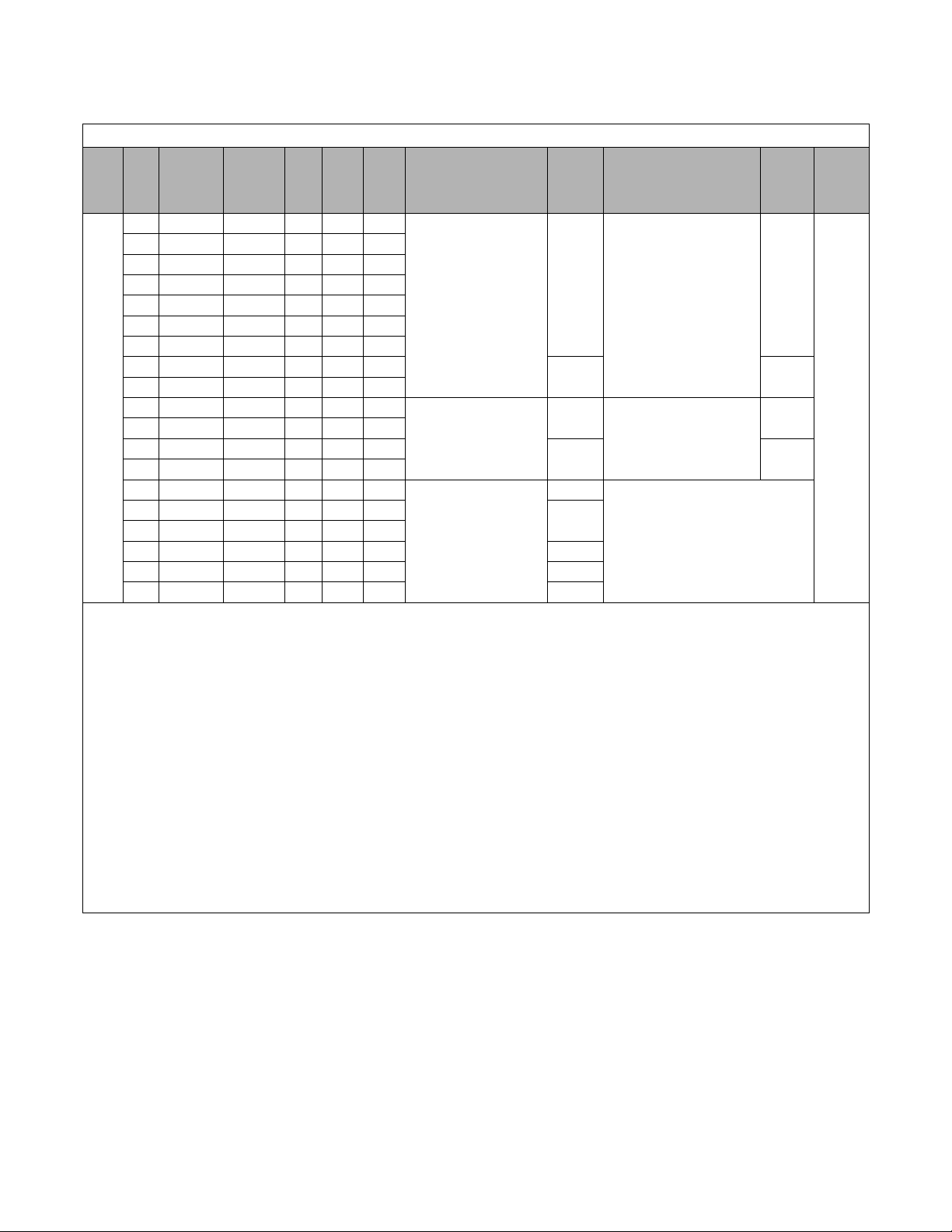
Quick Reference for Bypass Parameters
Parameter
Number
Factory
Setting
User
Setting
Parameter
Number
Factory
Setting
User
Setting
Parameter
Number
Factory
Setting
User
Setting
Parameter
Number
Factory
Setting
User
Setting
A1-00 0 b5-04 100 E1-05 240V or 480V L1-05 0.2
A1-01 2 b5-06 100 E1-06 60 L2-01 2
A1-03 0 b5-07 0 E1-07 3 L2-02 0.1
A1-04 0 b5-08 0 E1-08 18 L2-03 0.1
A1-05 0 b5-09 0 E1-09 1.5 L2-04 0.3
A2-01 b5-10 1 E1-10 10.8 L2-05 190
A2-02 b5-11 0 E1-11 0 L3-01 1
A2-03 b5-12 0 E1-12 0 L3-02 120
A2-04 b5-13 0 E1-13 0 L3-04 1
A2-05 b5-14 1 E2-01 kVA Dep. L3-05 1
A2-06 b5-15 0 E2-03 kVA Dep. L3-06 120
A2-07 b5-16 0 E2-05 kVA Dep. L4-01 0
A2-08 b5-17 0 F6-01 3 L4-02 2
A2-09 b5-18 0 F6-02 0 L4-05 0
A2-10 b5-19 0 F6-03 1 L4-06 80
A2-11 b5-20 1 F6-05 0 L5-01 10
A2-12 b5-21 1 H1-01 70 L5-02 0
A2-13 b5-22 0 H1-02 L5-03 600
A2-14 b5-23 0 H1-03
See Table 2 of
the bypass
schematic
L6-01 6
A2-15 b5-24 0 L6-02 15
A2-16 b5-25 0 L6-03 10
A2-17 b5-26 0 H1-04 4 L8-01 0
A2-18 b5-27 60 H1-05 6 L8-02 95
A2-19 b5-28 0 H2-01 0 L8-03 4
A2-20 b5-29 1 H2-02 3B L8-06 5
A2-21 b5-30 0 H3-02 See Table 2 of
the bypass
schematic
L8-09 1
A2-22 b8-01 1 L8-10 0
A2-23 b8-04 kVA Dep. L8-11 300
A2-24 b8-05 20 H3-03 0 L8-12 45
A2-25 b8-06 0 H3-08 See Table 2 of
the bypass
schematic
L8-15 1
A2-26 C1-01 60 L8-18 1
A2-27 C1-02 60 L8-19 20
A2-28 C1-03 30 H3-09 See T able 2 of
the bypass
schematic
n1-01 1
A2-29 C1-04 30 n1-02 1
A2-30 C1-09 10 n3-01 5
A2-31 C1-11 0 H3-10 100 n3-02 150
A2-32 C2-01 0.2 H3-11 0 n3-03 1
b1-01 See T able 2 of
the bypass
schematic
C2-02 0.2 H3-12 0.3 n3-04 40
C4-01 1 H3-13 See Table 2 of
the bypass
schematic
o1-01 6
C4-02 200 o1-02 1
b1-02 1 C6-02 kVA Dep. o1-03 0
b1-03 0 C6-03 kVA Dep. H4-01 2 o1-05 3
b1-04 1 C6-04 kVA Dep. H4-02 100 o1-06 0
b1-07 1 C6-05 0 H4-03 0 o1-07 2
b1-08 1 d1-01 10.0 H4-04 8 o1-08 3
b1-11 0 d1-02 6.0 H4-05 50 o2-01 1
b1-12 0 d1-03 0 H4-06 0 o2-02 0
b2-01 0.5 d1-04 40 H4-07 0 o2-03 0
b2-02 50 d1-17 6 H4-08 0 o2-04 kVA Dep.
b2-03 5.0 d2-01 100 H5-01 1F o2-05 1
b2-04 0 d2-02 0 H5-02 3 o2-06 1
b2-09 0 d2-03 0 H5-03 0 o2-07 0
b3-01 2 d3-01 0 H5-04 3 o2-08 1
b3-02 120 d3-02 0 H5-05 1 o2-09 1
b3-03 2 d3-03 0 H5-06 5 o2-10 0
b3-05 0.2 d3-04 1 H5-07 1 o2-12 0
b3-14 1 d4-01 0 H5-08 0 o2-14 0
b4-01 0 d4-02 10 H5-09 2 o2-15 0
b4-02 0 E1-01 208, 240V or
480V
L1-01 1 o3-01 0
b5-01 0 L1-02 8 o3-02 1
b5-02 2 E1-03 F L1-03 3 T1-02 kVA Dep.
b5-03 5 E1-04 60 L1-04 1 T1-04 kVA Dep.
Page 3

Warnings and Cautions
This Section provides warnings and cautions perti nent to this product, that if not
heeded, may result in personal injury, fatality, or equipment damage. Yaskawa is
not responsible for consequences of ignoring these instructions.
WARNING
YASKAWA manufactures component parts that can be used in a wide variety of industrial applications. The selection and
application of YASKAWA products remain the responsibility of the equipment designer or end user. YASKAWA accepts no
responsibility for the way its products are incorporated into the final system design. Under no circumstances should any
YASKAWA product be incorporated into any product or design as the exclusive or sole safety control. Without exception, all
controls should be designed to detect faults dynamically and fail safely under all circumstances. All products designed to
incorporate a component part manufactured by YASKAWA must be supplied to the end user with appropriate warnings and
instructions as to that part’s safe use and operation. Any warnings provided by YASKAWA must be promptly provided to the
end user. YASKAWA offers an express warranty only as to the quality of its products in conforming to standards and
specifications published in the YA SKAWA manual. NO OTHER WARRANTY, EXPRESS OR IMPLIED, IS OFFERED.
YASKAWA assumes no liability for any personal injury, property damage, losses, or claims arising from misapplication of its
products.
WARNING
• Read and understand this manual before installing, operating, or servicing this Drive. All warnings, cautions, and
instructions must be followed. All activity must be performed by qualified personnel. The Drive must be installed according
to this manual and local codes.
• Do not connect or disconnect wiring while the po we r is on. Do not remov e covers or t ou ch ci rcuit boar ds while the po wer is
on.
• Before servicing, disconnect all power to the equipment. The internal capacitor remains charged even after the power supply
is turned off. Status indicator LEDs and Digital Operator display will be extinguished when the DC bus voltage is below
50 VDC. To prevent electric shock, wait at least five minutes after all indicators are OFF and measure DC bus voltage level
to confirm safe level.
• Do not perform a withstand voltage test on any part of the unit. This equipment uses sensitive devices and may be damaged
by high voltage.
• The Drive an d Bypass unit is not s uitable for circuits capable of deliv ering more than the specified RMS symmetrical
amperes. Install adequate branch short circuit protection per applicable codes. Refer to the specification. Failure to do so
may result in equipment d amage and/or personal inj ury.
• Do not connect unapproved LC or RC interference suppression filters, capacitors, or overvoltage protection devices to the
output of the Drive. These devices may generate peak currents that exceed Drive specifications.
• To avoid unnecessary fault displays caused by contactors or output switches placed between Drive and motor, auxiliary
contacts must be properly integrated into the control logic circuit.
• YASKAWA is not responsible fo r any modification of the product m ade by the user; doing so will void the warranty. This
product must not be modified.
• Verify that the rated voltage of the Drive and Bypass un it matches the voltag e of the inco ming pow er supply befor e applyin g
power.
• To meet CE directives, proper line filters and proper installation are required.
i
Page 4

WARNING
• Some drawin gs in this manual may be shown with protectiv e covers or shields removed, to descr ibe details. These must be
replaced before operation.
• Observe electrostatic discharge procedures when handling circuit cards to prev ent ESD damage.
• The equipment may start unexpectedly upon application of power. Clear all personnel from the Drive, motor, and machine
area before applying power. Secure covers, couplings, shaft keys, and machine loads before energizing the Drive and By pass
unit.
• Please do not connect or operate any equipment with visible damage or missing parts. The op erating company is responsible
for any injuries or equipment damage resulting from failure to heed the warnings in this manual.
! Intended Use
Drives and Bypass Units are intended for installation in electrical systems or machinery.
For use in the European Union, the installation in machinery and systems must conform to the following product standards of
the Low Voltage Directive:
EN 50178, 1997-10, Equipping of Power Systems with Electronic Devices
EN 60201-1, 1997-12 Machine Safety and Equipping with Electrical Devices
Part 1: General Requirements (IEC 60204-1:1997)/
EN 61010, 1997-11Safety Requirements for Information Technology Equipment
(IEC 950:1991 + A1:1992 + A2:1993 + A3:1995 + A4:1996, modified)
CE certification per EN 50178 can be achieved using the line filters specified in this manual and following the appropriate
installation instructions.
!Other
The Drive and Bypass unit is suitable for use on a circuit capable of delivering not more than 100,000 RMS symmetrical
amperes, 240Vac maximum (240V Class) and 480Vac maximum (480V Class).
This manual is for reference only and subject to change without notice.
ii
Page 5

Introduction
This Section describes the applicability of the Manual
! Product Description
The P7 Bypass unit provides a means of bypassing the Drive while allowing the motor to operate at full speed, directly from
the AC line. It incorporates an AC Drive and three contactor Bypass arrangement in a single UL listed enclosure. The three
electrically interlocked IEC rated contactors isolate the Drive when operating in Bypass mode.
Control logic provides industry standard Hand/Off/Auto functions and safety circuit interlocks in both drive and Bypass
operating modes.
Bypass components include: a fused 120 VAC control circuit transformer, an input Motor Circuit Protector (MCP) circuit
breaker/disconnect, motor overload relay, selector switches and indicating lights.
The P7 Drive, a component of the P7 Bypass package, is a Pulse Width Modulated Drive for 3-Phase AC induction motors.
This type of Drive is also known as an Adjustable Frequency Drive, Variable Frequency Drive, AC Drive, AFD, ASD, VFD,
and Inverter. In this manual, the P7 Drive will be referred to as the “Drive”.
The Drive is a variable torque AC drive, designed specifically for HVAC applications, including fans, blowers and pumps. A
new benchmark for size, cost, performance, benefits, and quality, the Drive includes numerous
built-in features such as network communications, H/O/A, PI, parameter storage and copy functions.
The Drive has communications for the popular protocols: DeviceNet, Profibus, Ethernet, etc. An optional L
interface card is also available.
The LCD keypad/operat or is equi p ped wit h Hand/ Off/Auto functions, copy feature, 7 language choices, and 5 li nes of di s play
with 16 characters per line. User parameter settings can be recovered at any time via “User Initialization”. Optional
DriveWizard software allows upload/download, as well as graphing and monitoring of drive parameters from a PC for ease of
drive management.
Built-in PI eliminates the need for closed loop output signals from a building automation system. It includes feedback display,
inverse, square root and differential control functions, and maintains setpoint for closed loop control of fans and pumps for
pressure, flow, or temperature regulation.
This manual is applicable to P7 Drives defined by model numbers of CIMR-P7U_ _ _ _ contained within Bypass units
defined by model numbers of P7B_ _ _ _.
This manual is subject to change as product improvements occur. The latest version of the manual can be obtained from the
Yaskawa website www.drives.com
of Drive software is also shown.
. The date shown on the rear cover is changed when revisions are made. The latest version
ONWORKS®
Introduction iii
Page 6

This manual may describe trademarked equipment, which is the property of other companies. These trademarks are the
property of the registered owner companies and may include the following:
®
PROFIBUS
DeviceNet is a registered trademark of ODVA (Open DeviceNet Vendor Association, Inc.)
Modbus
ONWORKS
L
Other Documents and Manuals are available to support special use or installation of this product. These documents may be
provided with the product or upon request or downloaded from www.drives.com. Documents may include the following:
TM.P7.02.Programming … Manual included on CD ROM with product
DriveWizard … Software and Manual…Included on CD ROM with product
Option Instructions … Included on CD ROM with product
and PROFIBUS-DP® are registered trademarks of PROFIBUS Nutzerorganization e.v.
®
, trademark of Schneider Automation, Inc.
®
, trademark of Echelon Corporation
! Definitions of Acronyms and Abbreviations
AC Alternating Current LRA Locked Rotor Amperes
AIC Amps Interrupting Capacity MCP Motor Circuit Protector
CB Circuit Breaker MTBF Mean Time Between Failures
CIMR Control Induc tion Motor Rotation NC Normally Closed
CN Connector NEC National Electrical Code
CPT Control Power Transformer NEMA National Electrical Manufacturers Association
CPU Central Processing Unit NO Normally Open
DIP Dual Inline Package OLR Over Load Relay
FLA Full Load Amperes PCB Printed Circuit Board
FVFF Forced Ventilated, inlet Filter, outlet Filter PI Proportional plus Integral control action
HOA Hand/Off/Auto SFS Soft Start
HP Horsepower TB T ermin al Block
IEC International Electrotechnical Commission THD Total Harmonic Distortion
IGV Inlet Guide Vanes VA Volt Amperes
IPM Intelligent Power Module VAC Volts Alternating Current
KVA Kilo Volt Amperes VAV Variable Air Volume
LED Light Emitting Diode
! Terminology in This Manual
“Standard” or “Configured” options - are available with standard lead times
“Engineered” or “Custom” options - are available only with extended lead times
Introduction iv
Page 7

! Resources Available
Document Number Description
TM.P7.01 Drive User Manual
TM.P7.02 Drive Progr a mming Manual
TM.AFD.14 DeviceNet Technical Manual
TM.AFD.12 Profibus Technical Manual
Table of Resources
Manuals, Installation Guides, and CD’s
IG.AFD.20 LONWORKS
IG.AFD.50 3-15 PSI Pressure Transducer Installation Guide
CD.AFD7.01 CD ROM for Drives
Document Description
DriveWizard® Software DriveWizard® Software Version 5.3 o r l a ter
® Option Installation Guide
Software
Introduction v
Page 8

Notes:
Introduction vi
Page 9

Table of Contents
Quick Reference Parameter List ........................................................Inside front cover
Warnings and Cautions................................................................................................ i
Introduction..................................................................................................................iii
Chapter 1 - Physical Installation ...............................................................................1-1
Bypass Model Number and Enclosure Style .............................................................. 2
Enclosure Data ........................................................................................................... 4
Confirmations upon Delivery ...................................................................................... 7
Bypass Product Options ............................................................................................. 9
Bypass Component Descriptions ............................................................................. 11
Exterior and Mounting Dimensions .......................................................................... 17
Checking and Controlling Installation Site ................................................................ 24
Chapter 2 - Electrical Installation..............................................................................2-1
Termination Configuration - Power Wiring ................................................................. 2
Control Wiring ............................................................................................................. 9
Wiring Diagram ......................................................................................................... 20
Logic Diagram .......................................................................................................... 22
Chapter 3 - Digital Operator.......................................................................................3-1
Digital Operator and Control Panel Display ...............................................................2
Drive Main Menus ......................................................................................................8
Example of Changing a Parameter ..........................................................................16
Chapter 4 - Start Up and Operation ..........................................................................4-1
Start Up Introduction ..................................................................................................2
Bypass Start Up Preparation.......................................................................................3
Bypass Unit Start Up Procedure .................................................................................4
Bypass Operation Description.....................................................................................8
Chapter 5 - Programming ..........................................................................................5-1
Bypass Basic Programming Parameters ...................................................................2
Table of Contents vii
Page 10

Chapter 6 - Diagnostics & Troubleshooting ........................................................... 6-1
Bypass Diagnostics ....................................................................................................2
Drive Diagnostics .......................................................................................................3
Drive Troubleshooting ..............................................................................................16
Drive Main Circuit Test Procedure ............................................................................22
Drive Date Stamp Information ..................................................................................26
Chapter 7 - Maintenance............................................................................................7-1
Maintenance ...............................................................................................................2
Removing and Replacing Drive in a Bypass Unit .......................................................9
Appendix A - Parameters..........................................................................................A-1
Parameter List ............................................................................................................2
Monitor List ...............................................................................................................26
Fault Trace List ........................................................................................................28
Fault History List ......................................................................................................29
Appendix B - Capacity Related Parameters............................................................B-1
Drive Capacity ............................................................................................................2
Appendix C - Specifications.....................................................................................C-1
Standard Drive and Bypass Specifications .................................................................2
Appendix D - Communication ..................................................................................D-1
Using Modbus Communication ..................................................................................2
Modbus Function Code Details ..................................................................................7
Modbus Data Tables ..................................................................................................9
Modbus Self-Diagnosis ............................................................................................14
Appendix E - Peripheral Devices ............................................................................. E-1
General Peripheral Devices .......................................................................................2
Table of Contents viii
Page 11

Appendix F - Replacement Parts ............................................................................. F-1
Primary Parts - 208/230/240VAC ...............................................................................2
Primary Parts - 480VAC .............................................................................................3
Bypass Replacement Parts.........................................................................................4
Table of Contents ix
Page 12

Notes:
Table of Contents x
Page 13

Chapter 1
Physical Installation
This chapter describes the checks required upon receiving
and the installation process for a Drive and Bypass unit.
Bypass Model Number and Enclosure Style ..................................2
Enclosure D a ta .................... ... .. .......................................... ............ 4
Confirmations upon Delivery ..........................................................7
Receiving C h e c ks .................. .. .. ............................. ...................7
Bypass Namep la te Information ............................. ..................... 7
Bypass Unit Enc l o s u re s ..... ............................ ............................ 8
Bypass Product Options .................................................................9
Bypass Component Descriptions ................................................. 11
Bypass Unit Front Control Panel ............................................ 11
Exterior and Mounting Dimensions ........................ ......................17
Bypass Unit 30 HP and Below, 480 VAC;
15 HP and Below, 208V/240V .................................................17
Bypass Unit 30 HP and Below, 480 VAC;
15 HP and Below, 208V/240V With Add-On Box ...................18
Bypass Unit 40 HP to 100 HP, 480 V AC;
20 HP to 40 HP, 208V/240V ....................................................19
Bypass Unit 40 HP to 100 HP, 480 V AC;
20 HP to 40 HP, 208V/240V With Add-On Box ........................20
Bypass Unit 125 HP to 250 HP, 480 VAC;
50 HP to 125 HP, 208V ................................................. ...........21
Dimensions and Weights ................................ .........................22
Checking and Controlling Installation Site ....................................24
Installation Site ........................................................................ 24
Controlling the Ambient Temperature ......................................25
Protecting the Bypass Unit fr om Foreign Matter ............... .......25
Installation Orientation and Enclosure Considerations ............26
Physical Installation 1 - 1
Page 14

Bypass Model Number and Enclosure Style
The Bypass covers two voltage ranges: 208-240 VAC and 480 VAC. Ratings applicable are from 1/2 to 500 HP.
Table 1.1 Bypass
Voltage
208 VAC
240 VAC
Bypass
Base Model Number
NEMA 1
P7BVD002 P7BBD002 0.5 2.4 CIMR-P7U22P2
P7BVD003 P7BBD003 0.75 3.5 CIMR-P7U22P2
P7BVD004 P7BBD004 1 4.6 CIMR-P7U22P2
P7BVD007 P7BBD007 2 7.5 CIMR-P7U22P2
P7BVD010 P7BBD010 3 10.6 CIMR-P7U22P2
P7BVD016 P7BBD016 5 16.7 CIMR-P7U23P7
P7BVD024 P7BBD024 7.5 24.2 CIMR-P7U27P5
P7BVD030 P7BBD030 10 30.8 CIMR-P7U27P5
P7BVD046 P7BBD046 15 46.2 CIMR-P7U2011
P7BVD059 P7BBD059 20 59.4 CIMR-P7U2015
P7BVD074 P7BBD074 25 74.8 CIMR-P7U2018
P7BVD088 P7BBD088 30 88 CIMR-P7U2022
P7BVD114 P7BBD114 40 114 CIMR-P7U2030
P7BVD143 P7BBD143 50 143 CIMR-P7U2037
P7BVD169 P7BBD169 60 169 CIMR-P7U2045
P7BVD211 P7BBD211 75 211 CIMR-P7U2055
P7BVD273 P7BBD273 100 273 CIMR-P7U2075
P7BVD343 P7BBD343 125 343 CIMR-P7U2090
P7BVD396 P7BBD396 150 396 CIMR-P7U2110
P7BVA002 P7BBA002 0.5 2.2 CIMR-P7U22P2
P7BVA003 P7BBA003 0.75 3.2 CIMR-P7U22P2
P7BVA004 P7BBA004 1 4.0 CIMR-P7U22P2
P7BVA006 P7BBA006 2 6.8 CIMR-P7U22P2
P7BVA009 P7BBA009 3 9.6 CIMR-P7U22P2
P7BVA015 P7BBA015 5 15.2 CIMR-P7U23P7
P7BVA022 P7BBA022 7.5 22 CIMR-P7U25P5
P7BVA028 P7BBA028 10 28 CIMR-P7U27P5
P7BVA042 P7BBA042 15 42 CIMR-P7U2011
P7BVA054 P7BBA054 20 54 CIMR-P7U2015
P7BVA068 P7BBA068 25 68 CIMR-P7U2018
P7BVA080 P7BBA080 30 80 CIMR-P7U2022
P7BVA104 P7BBA104 40 104 CIMR-P7U2030
*NEMA 12
FVFF
HP
Bypass
Continuous
Output
Current
(Amps)
Uses
Basic Drive
Model-Number
Physical Installation 1 - 2
Page 15

Table 1.1 Bypas s
Bypass
Base Model Number
Voltage
NEMA 1
P7BVA130 P7BBA130 50 130 CIMR-P7U2037
P7BVA154 P7BBA154 50 154 CIMR-P7U2037
230 VAC
480 VAC
* The Nema 12 FVFF Enclosure is ventilated and filtered with gaskets. UL does not recogniz e NE MA 12
ventilated enclosures, therefore, for UL purposes, these units are designated NEMA 1.
P7BVA192 P7BBA192 60 192 CIMR-P7U2045
P7BVA248 P7BBA248 75/100 248 CIMR-P7U2075
P7BVA312 P7BBA312 125 312 CIMR-P7U2075
P7BVA360 P7BBA360 150 360 CIMR-P7U2090
P7BVB001 P7BBB001 0.5 1.1 CIMR-P7U42P2
P7BVB001 P7BBB001 0.75 1.6 CIMR-P7U42P2
P7BVB002 P7BBB002 1 2.1 CIMR-P7U42P2
P7BVB003 P7BBB003 2 3.4 CIMR-P7U42P2
P7BVB004 P7BBB004 3 4.8 CIMR-P7U42P2
P7BVB007 P7BBB007 5 7.6 CIMR-P7U43P7
P7BVB011 P7BBB011 7.5 11 CIMR-P7U45P5
P7BVB014 P7BBB014 10 14 CIMR-P7U47P5
P7BVB021 P7BBB021 15 21 CIMR-P7U4011
P7BVB027 P7BBB027 20 27 CIMR-P7U4011
P7BVB034 P7BBB034 25 34 CIMR-P7U4015
P7BVB040 P7BBB040 30 40 CIMR-P7U4018
P7BVB052 P7BBB052 40 52 CIMR-P7U4030
P7BVB065 P7BBB065 50 65 CIMR-P7U4030
P7BVB077 P7BBB077 60 77 CIMR-P7U4037
P7BVB096 P7BBB096 75 96 CIMR-P7U4045
P7BVB124 P7BBB124 100 124 CIMR-P7U4055
P7BVB156 P7BBB156 125 156 CIMR-P7U4075
P7BVB180 P7BBB180 150 180 CIMR-P7U4090
P7BVB240 P7BBB240 200 240 CIMR-P7U4110
P7BVB302 P7BBB302 250 302 CIMR-P7U4160
*NEMA 12
FVFF
(Continued)
HP
Bypass
Continuous
Output
Current
(Amps)
Uses
Basic Drive
Model-Number
Physical Installation 1 - 3
Page 16
Enclosure Data
Table 1.2 208V Enclosure Data
Input
HP
Volts
0.75 P7U22P21A P7B_D003 3.5 3.8 68
208
Drive
1
Model
CIMR-
0.5 P7U22P21A P7B_D002 2.4 2.6 68
1 P7U22P21A P7B_D004 4.6 5.1 78
2 P7U22P21A P7B_D007 7.5 8.2 110
3 P7U22P21A P7B_D010 10.6 11.7 141
5 P7U23P71A P7B_D016 16.7 18.4 202
7.5 P7U27P51A P7B_D024 24.2 26.6 273
10 P7U27P51A P7B_D030 30.8 33.9 365
15 P7U20111A P7B_D046 46.2 50.8 578
20 P7U20151A P7B_D059 59.4 65.3 653
25 P7U20181A P7B_D074 74.8 82.3 746
30 P7U20221A P7B_D088 88.0 96.8 939
40 P7U20301A P7B_D114 114.0 125.4 1340
50 P7U20370A P7B_D143 143.0 157.3 1523
60 P7U20450A P7B_D169 169.0 185.9 1762
75 P7U20550A P7B_D211 211.0 232.1 2244
100 P7U20750A P7B_D273 273.0 300.3 3003 1214 lbs
125 P7U20900A P7B_D343 343.0 377.3 3296 1330 lbs
150 P7U21100A P7B_D396 396.0 435.6 4029 1423 lbs
Bypass
Model
Number
2
NEC
FLA
OL
110%
1 min
Note 1: Horsepower rating is based on a standard NEMA B 4-pole motor.
3
Heat
Loss
NEMA 1 & NEMA 12 -FVFF
Watts
H W D
29.48 19.06 13.66
40.48 25.63 14.66
84.00 25.63 26.25
Enclosure Dimensions
inches
Dimension Drawing
S-5542
Dimension Drawing
S-5544
Dimension Drawing
S-5550
4
Weight
Assembly
115 lbs
6
127 lbs 164 lbs
208 lbs
7
221 lbs 307 lbs
847 lbs
8
943 lbs
9
Enclosure Dimensions w/Add-on
5
of
NEMA 1 & NEMA 12-FVFF
H W D
43.35 19.06 13.66
55.35 25.63 14.66
inches
Dimension Drawing
S-5543
Dimension Drawing
S-5545
NOT REQUIRED
4
Weight5 of
Assembly
+Add-on
156 lbs
291 lbs
Electrical
Schematic
Box
P7B-00
Note 2: The underscore position in these model numbers codes for the encl osur e type: V = N EMA1, B = NEM A12 FVF F.
Note 3: Heat loss is the amount of heat dissipated by the drive at full load with all standard options availa ble inside the enclosure. Drive heat sink losses are
included in the heat loss data. Heat loss data is for the enclosure without the add-on enclosure.
Note 4: Height dimension (H) excludes the mounting screw tabs. Depth dimension (D) excludes MCP disconnect handle.
Note 5: This data represents the total weight with all possibl e stan dard options. Weight could be less depending on the options specified.
Note 6: All standard options are available in this size enclosur e exce pt options E (RFI Filter) and K (5% Output Reactor ) . Opt ions E and K require the ad d- on
enclosure.
Note 7: All options are available in this size enclosure except E (RFI Filter), R (3% Line Reactor), and K (5% Output Reactor). Only option E combined with
either option R or option K can be installe d in the add-on enclosure. Options R and K together require an increase in the size of the P7 Bypass Enclosure.
Contact the factory if all three options a re r equ ir ed . Options D (2 Motor “OR”) or A (2 Motor “AND”) for 30 Hp and 40 Hp require the next
size enclo s u re.
Note 8: Heat sink mounted externally varies the depth dimension depending on the drive size. Depth will not exceed dimension shown.
Note 9: All options are available in this size enclosure except options D (2 Motor “OR”) or A (2 Motor “AND”) for 75 Hp and 100 Hp require the next
size enclo s u re.
Physical Installation 1 - 4
Page 17

Table 1.3 240/230V Enclosure Data
Input
Volts
240
230
HP
Drive
1
Model
CIMR-
0.5 P7U22P21A P7B_A002 2.2 2.4 68
0.75 P7U22P21A P7B_A003 3.2 3.5 68
1 P7U22P21A P7B_A004 4.0 4.4 78
2 P7U22P21A P7B_A006 6.8 7.5 110
3 P7U22P21A P7B_A009 9.6 10.6 141
5 P7U23P71A P7B_A015 15.2 16.7 202
7.5 P7U25P51A P7B_A022 22.0 24.2 273
10 P7U27P51A P7B_A028 28.0 30.8 365
15 P7U20111A P7B_A042 42.0 46.2 578
20 P7U20151A P7B_A054 54.0 59.4 653
25 P7U20181A P7B_A068 68.0 74.8 746
30 P7U20221A P7B_A080 80.0 88.0 939
40 P7U20301A P7B_A104 104.0 114.4 1340
50 P7U20370A P7B_A130 130.0 143.0 1523
60 P7U20370A P7B_A154 154.0 169.4 1544
75 P7U20450A P7B_A192 192.0 211.2 1860
100 P7U20750A P7B_A248 248.0 272.8 3003 1214 lbs
125 P7U20750A P7B_A312 312.0 343.2 3045 1330 lbs
150 P7U20900A P7B_A360 360.0 396.0 3440 1423 lbs
Bypass
Model
Number
2
NEC
FLA
OL
110%
1 min
Note 1: Horsepower rating is ba sed on a standard NEMA B 4-pole motor.
3
Heat
Loss
Watts
Enclosure Dimensions
NEMA 1 & NEMA 12 -FVFF
H W D
29.48 19.06 13.66
Dimension Drawing
40.48 25.63 14.66
Dimension Drawing
84.00 25.63 26.25
Dimension Drawing
inches
S-5542
S-5544
S-5550
4
Weight
Assembly
6
7
8
9
Enclosure Dimensions w/Add-on
5
of
115 lbs
127 lbs 164 lbs
208 lbs
221 lbs 307 lbs
847 lbs
943 lbs
NEMA 1 & NEMA 12-FVFF
H W D
43.35 19.06 13.66
55.35 25.63 14.66
inches
Dimension Drawing
S-5543
Dimension Drawing
S-5545
NOT REQUIRED
4
Weight5 of
Assembly
+Add-on
156 lbs
291 lbs
Electrical
Schematic
Box
P7B-00
Note 2: Th e und erscor e position in these model numbers codes for the encl osure type: V = NEMA1, B = NEMA12 FVFF.
Note 3: Heat loss is the amount of heat dissipated by the drive at full load with all standard options available inside the enclosure. Drive heat sink losses are
included in the heat loss data. Heat loss data is for the enclosure without the add-on enc los ur e.
Note 4: Height dimension (H) excludes the mounti ng screw tabs. Depth dimension (D) excludes MCP disconnect handle.
Note 5: Th is da ta repr e se nts the total weight with all possible sta nda r d op ti ons. Weight could be less depending on the options specified.
Note 6: Al l sta nda r d opt ions are available in this size enclosu re ex cept options E (RFI Filter) and K (5% Output R eac tor ) . Options E and K require the add-on
enclosure.
Note 7: All options are available in this size enclosur e exce pt E ( RF I Filte r), R ( 3% Line Re a ct or ), and K (5% Output Reactor). Only option E combined with
either option R or option K can be installe d in the add-on enclosure. Options R and K together r eq uir e an incr e as e in the size of the P7 Bypass Enclosure.
Contact the factory if all three options are req uire d. Options D (2 Motor “OR”) or A (2 Motor “AND”) for 30 Hp and 40 Hp require the next size
enclosure.
Note 8: Hea t sink mounted externally varies the dep th dim e nsion depending on the drive size. Depth will not e xcee d dimension shown.
Note 9: All options are available in this size enclosure exc e pt options D (2 Motor “OR”) or A (2 Motor “AND”) for 75 Hp and 100 Hp require the next size
enclosure.
Physical Installation 1 - 5
Page 18

Table 1.4 480V Enclosure Data
Input
HP
Volts
0.75 P7U42P21A P7B_B001 1.6 1.8 57
480
Drive
1
Model
CIMR-
0.5 P7U42P21A P7B_B001 1.1 1.2 57
1 P7U42P21A P7B_B002 2.1 2.3 62
2 P7U42P21A P7B_B003 3.4 3.7 89
3 P7U42P21A P7B_B004 4.8 5.3 121
5 P7U43P71A P7B_B007 7.6 8.4 155
7.5 P7U45P51A P7B_B011 11.0 12.1 217
10 P7U47P51A P7B_B014 14.0 15.4 318
15 P7U40111A P7B_B021 21.0 23.1 404
20 P7U40111A P7B_B027 27.0 29.7 408
25 P7U40151A P7B_B034 34.0 37.4 485
30 P7U40181A P7B_B040 40.0 44.0 618
40 P7U40301A P7B_B052 52.0 57.2 1040
50 P7U40301A P7B_B065 65.0 71.5 1045
60 P7U40371A P7B_B077 77.0 84.7 1197
75 P7U40451A P7B_B096 96.0 105.6 1357
100 P7U40551A P7B_B124 124.0 136.4 1749
125 P7U40750A P7B_B156 156.0 171.6 2032
150 P7U40900A P7B_B180 180.0 198.0 2486
200 P7U41100A P7B_B240 240.0 264.0 2955 1240 lbs
250 P7U41600A P7B_B302 302.0 332.2 4225 1352 lbs
300 P7U41850A P7B_B361 361.0 397.1 4425
350 P7U41850A P7B_B414 414.0 455.4 4451
400 P7U42200A P7B_B477 477.0 524.7 5099
450 P7U42200A P7B_B515 515.0 566.5 5154
500 P7U43000A P7B_B590 590.0 649.0 7329
Bypass
Model
Number
2
NEC
FLA
OL
110%
1 min
Note 1: Horsepower rating is based on a sta nda rd NEMA B 4-pole motor.
3
Heat
Loss
NEMA 1 & NEMA 12 -FVFF
Watts
H W D
29.48 19.06 13.66
40.48 25.63 14.66
84.00 25.63 26.25
Enclosure Dimensions
inches
Dimension Drawing
S-5542
Dimension Drawing
S-5544
Dimension Drawing
S-5550
TBD
4
Weight
Assembly
115 lbs
6
127 lbs 164 lbs
142 lbs
203 lbs
232 lbs
7
241 lbs
8
943 lbs
9
Enclosure Dimensions w/Add-on
5
of
TBD
NEMA 1 & NEMA 12-FVFF
H W D
43.35 19.06 13.66
Dimension Drawing
55.35 25.63 14.66
Dimension Drawing
inches
S-5543
S-5545
NOT REQUIRED
4
Weight5 of
Assembly
+Add-on
156 lbs
189 lbs
281 lbs
319 lbs
332 lbs
Electrical
Schematic
Box
P7B-00
Note 2: The underscore position in thes e mode l numbers codes for the enclosure type: V = NEMA1, B = NEMA12 FVFF.
Note 3: Heat loss is the amount of heat dissipated by the drive at full load with all standard options available inside the enclosure. Drive heat sink losses are
included in the heat loss data. Heat los s dat a is for the en cl osur e without the add-on enclosure.
Note 4: Height dimension (H) excludes the mounting screw tabs. Depth dim ension (D) excludes MCP disconnect ha ndle.
Note 5: This data represents the tot al wei ght wit h al l possible standard options. Weight could be less depending on the options specified.
Note 6: All standard options are available in this size enclosure except options E (RFI Filter) and K (5% Output Reactor). Options E and K require the
add-on enclosure.
Note 7: All options are available in this size enclosure except E (RFI Filter), R (3% Line Reactor), and K (5% Output Reactor). Only option E combined with
either option R or option K can be installed in the ad d- on en closur e . Options R and K together require an increase in the size of the P7 Bypass Enclosure.
Contact the factory if all three options are required. Options D (2 Motor “OR”) or A (2 Motor “AND”) for 75 Hp and 100 Hp require the next
size enclo s u re.
Note 8: Heat sink mounted externally varies the depth dimension depending on the drive size. Depth will not exceed dimension shown.
Note 9: All options are available in this size enclosure except options D (2 Motor “OR”) or A (2 Motor “AND”) for 200 Hp and 250 Hp require the next
size enclo s u re.
Physical Installation 1 - 6
Page 19

Confirmations upon Delivery
! Receiving Checks
Check the following items as soon as the Drive and Bypass unit is delivered.
Table 1.5 Checks
Item Method
Has the correct model of Bypass unit been
delivered?
Is the Bypass unit damag e d in an y w ay?
Are any screws or other comp onents loose? Use a screwdriver or the appr opriate tool to check for tightness.
If you find any irregularities in the above items, contact the shipping company, the distributor or representative you purchased
the Bypass unit from or your Yaskawa office immediately.
The Bypass unit is thoroughly tested at the factory. Any damages or shortages evident when the equipment is received must be
reported immediately to the commercial carrier that transported the material. Shipping damage is not covered by the Yaskawa
warranty. After unpacking and inspecting for damage, verify that internal wire connections have not come loose during
shipment by spot checking wire terminations with a screwdriver or the appropriate tool .
Check the mo del numb er on the nam epla te o n the rig ht s ide o f the Byp ass unit.
Reconcile with packi ng slip and/or order information.
Inspect the entire exterior of the Bypass unit to see if there are any dents,
scratches or other damage resulting from shipping.
Bypass unit storage must be in a clean and d ry location. Main tain the factory packaging an d provid e cove ring as needed to protect the Bypass unit from construction site dirt, water, debris and traffic prior to and during construction.
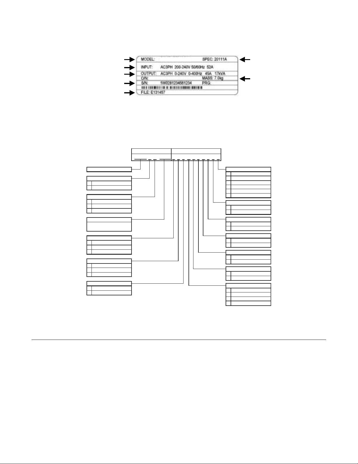
! Bypass Nameplate Information
A nameplate is attached to the right side of the enclosure and the inside of the door of each Bypass unit.
The nameplate shown below is an example for a standard Bypass unit.
A.C. INPUT
Volts: 480
Phase: 3
A.C. OUTPUT
Volts: 0-480
Phase: 3
Serial No: 4W033727440-0002
Model No: P7BVB065R
Type: P7 BYPASS
W.D.: P7B-00
Inst. Manual: TM.P7B.01,CD.AFD7.01
Hz: 50/60
Amps: 71.6
Hz: 0-60
Amps: 65
UNPN0001
Fig 1.1 Bypass Nameplate
(Example)
Physical Installation 1 - 7
Page 20
" Drive Nameplate Informa tion
V
V
A
A
X
r
A nameplate is also attached to the right side of the Drive inside the Bypass enclosur e. The f ollowing namep late is an ex ample
for a standard Drive.
Drive Model Number
Input Power Specifications
Output Power Specifications
Serial Number
UL File Number
CIMR-P7U2011
Fig 1.2 Drive Nameplate
(Example)
Drive Enclosure and
Revision Code
Weight
" Bypass Unit Model Numbers
The model number on the nameplate of the Bypass unit indicates the enclosure, voltage, Drive rated current and options of the
Bypass unit in alphanumeric codes.
BASE NUMBER OPTIONS
P 7 B 0 9 6
B - - - R - - S - - L
P7 B
ypass Configuraton
Enclosure
NEMA 1
B
NEMA 12
Voltage
D
208V
230/240V
B
480V
Current
NEC Rated Amps
(Ex.: "096" = 96A)
Motor Control
-
1 Motor (Standard)
D
otor "OR"
2 M
2 Motor "AND"
Input Filter
-
None (Leave Blank)
N
Cap Filter
E
RFI Filte
Input Fuses
-
None (Leave Blank)
Fuses
F
(1)3% and 5% Bus Reactors are only available as an option on Drives up to
25HP at 208V and 30HP at 480V; larger Drives have a Bus Reactor as standard
(2)3% Input Reactor, when combined with the standard Bus Reactor (available on
drives above 25HP at 208V and 30HP at 480V), yields a total of 5% input
impedance
Fig 1.3 Bypass Unit Model Number
Communications
-
Not Enabled (Leave Blank)
G
DeviceNet
H
Profibus
L
LonWorks
Q
Ethernet
V
Modbus (Internal)
4-20mA Outp ut
-
None (Leave Blank)
M
4-20mA Output
3-15 PSI Transducer
None (Leave Blank)
P
3-15 PSI Tr ansducer
Speed Pot
-
None (Leave Blank)
S
Speed Pot
Custom Nameplates
-
None (Leave Blank)
W
Custom Nameplates
Load Reactor
-
None (Leave Blank)
K
5% Load Reactor
Line Impedance
None (Leave Blank)
-
3% Bus Re actor
Z
5% Bus Re actor
R
3% Input Reactor
(1)
(1)
(2)
! Bypass Unit Enclosures
All Bypass units are intended for non-hazardous locations. Various enclosure types are provided to protect against the application environmental conditions:
Nema Type 1 Enclosures are constructed for indoor use to provide a degree of protection against incidental contact with
enclosed electrical equipment and falling dust or dirt.
NEMA Type 12 FVFF Enclosures. NEMA provides for both non-ventilated and ventilated NEMA 12 enclosures. When
ventilated, a suffix to the type number d efines the ventilation method. A NEMA 12 FVFF enclosure has Forced Ventilation
with inlet air Filter and outlet air Filter. The internal pressure is positive with respect to the ambient pressure. UL does not
recognize NEMA 12 ventilated enclosures, therefore, these enclosures are designated NEMA 1 for UL purposes.
Physical Installation 1 - 8
Page 21

Bypass Product Options
Option A - Two motor “AND” control: Allows the operation of two motors from one Drive or Bypass. Pump #1 “AND”
pump #2 are operated at the same speed via the output from one Drive or Bypass. The motors are always operated
simultaneously therefore, no transfer switch is involved. With the 2 motor “AND” option, motor OverLoad Relays and fuses
are provided for each motor and the Drive’s internal motor overload function is disabled.
The two motors can be of different capacity if this capacity difference was considered in the ordering process. The factory
needs to know the FLA value of each motor controlled in order to select the correct motor overload devices and fuses.
(Specifying different capacity motors results in longer, non-standard lead times).
Option D - Two motor “OR” control: A MTR #1/AUTO/MTR #2 selector switch is provided to allow local or remote motor
operation selection, between two identical motors, for control by either the Drive or the Bypass (for example, Pump #1 “OR”
AUTO “OR” Pump #2). In the AUTO position, a customer supplied contact closure at TB1 terminals 23 and 24 can switch
between the two motors. The two motors must be the same horsepower and current draw.
Option E - RFI/EMI Filter: Filters to further attenuate possible VFD generated noise. Radio frequency interference/electro
magnetic interference filters reduce conducted noise on the Drive input power leads and therefore, radiated noise from those
leads. This option is installed on the input power side of the Drive, between the input contactor and the Drive.
Option F - Drive Input Fuses: Fuses capable of protecting semiconductor devices, r ated at 200 kAIC ar e connected to th e line
side of the Drive, between the input contactor and the Drive, to protect the Drive semiconductors when motor or output
conductor short circuit faults occur.
Option G - Serial Communication, DeviceNet: An option card that provides DeviceNet protocol for network communication.
Option H - Serial Communication, Profibus: An option card that provides Profibus protocol for network communication.
Option K - 5% Output Reactor: Employed on the output side of the Drive for reduction of peak voltages a pplied to the dr iven
motor . In long Drive to motor lead length si tuat ions , hi g h carrier frequency and reflected waves can cause high voltage spikes
at the motor . An ou tput reactor provides motor p rotection in these long motor lead leng th situations. Th is option is installed on
the output power side of the Drive, between the output contactor and the Drive.
Option L - Serial Communication, Echelon LonWorks: An isolated RS-422/485 circuit board provides LonTalk protocol for
network communication. This option plugs into the CN2 connection on the Drive control circuit board.
Option M - 4 to 20 mA Output: Provides two programmable 0 to 10 VDC analog outputs or two programmable 4 to 20 mA
analog outputs.
Option N
of voltage distortion and electrical noise. This passive wye-delta capacitve filter is intended for installation on the VFD input in
order to protect other sensitive electronic loads, it provides attenuation of conducted RFI and EMI.
Option P - Pressure to Electrical Transducer: This tran sducer is employed when converting a pneumatic signal to an electrical
signal for use as the Drive speed command input. The need for this option comes up on retrofit applications when the
pneumatic signal that formerly controlled the pneumatic actuator on Inlet Guide Vanes (IGV), for example, is now to be used
to control the fan speed via the Drive. This option is wired to Drive terminals +V, A2 and AC, parameters H3-10 and
H3-11 are used for final field calibration of this input if there is jobsite variation from the typical 3 to 15 PSIG pneumatic
signal input range.
- Input Capacitive Network Radio Frequency Interference Filter: Electronic equipment can be sensitive to low le vels
Physical Installation 1 - 9
Page 22

Option Q - Serial Communication , Et her net : An op t ion car d t hat provides Modbus TCP proto col fo r netw or k com munication.
Option R - 3% Input Line Reactor: Employed on the input side of the Drive for Total Harmonic Distortion (THD) suppres-
sion. A line reactor also minimizes the potential for Drive input diode damage from line transients and reduces voltage peaks
on the DC bus capacitors. This option is installed on the input power side of the Drive, between the input contactor and the
Drive.
Option S - Speed Potentiometer: A door mounted single turn potentiometer for manual control of Drive output and motor
speed. This option is wired to Drive terminals +V, A1 and AC and is used as the local speed command input to the Drive
instead of the keypad up and down arrows. Parameters for use of this option in conjunction with other input signals are
detailed in Table 5.2.
Option V - Embedded Serial Communication, Modbus: A no cost option. The Drive in a Bypass unit is capable of Modbus
network communication via the standard RS-422/485 terminals.
Option W - Engraved Plastic Nameplate: An enclosure identification namep late to carry the controlled equipment “tag
number”.
Option X - 3% DC Bus Reactor: Attenuates harmonic distortion by limiting the rate of rise of the input current. The bus
reactor is wired to the Drive (+1) and (+2) DC bus terminals to provide the equivalent impedance of a 3% input reactor. This
option is only used on the low end of the horsepo wer range where DC bu s reactors are not a s tandard Drive co mponent (25 HP
and below @ 208 VAC, 25 HP and below @ 240 VAC, and 30 HP and below @ 480 VAC.)
Option Z - 5% DC Bus Reactor: Attenuates harmonic distortion by limiting the rate of rise of the input current. The bus
reactor is wired to the Drive (+) and (-) DC bus terminals to provide the equivalent impedance of a 5% input reactor. This
option is only used on the low end of the horsepower range where DC bus reactors are not a standard Drive component
(25 HP and below @ 208 VAC, 25 HP and below @ 240 VAC, and 30 HP and below @ 480 VAC.)
Physical Installation 1 - 10
Page 23
Bypass Component Descriptions
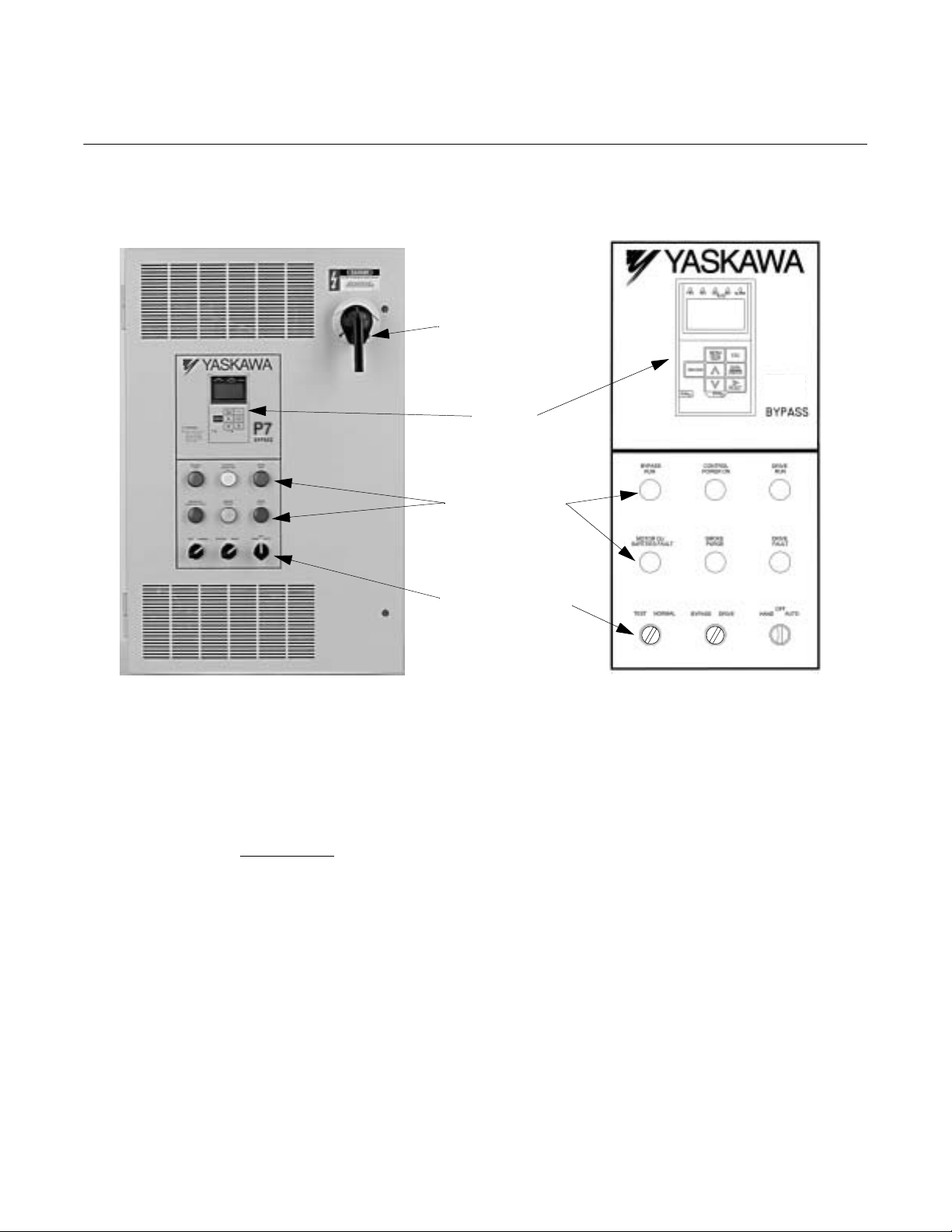
! Bypass Unit Front Control Panel
The external appearance, component names, an d term inal arr angem ent o f t he By pas s uni t i s s hown i n Fi gu res 1.4 through 1.8.
MCP
Disconnect
P7
Keypad
Operator
Indicating Lights
Selector Switches
Fig 1.4 E7 Bypass Unit Appearance
" Keyp ad Operator
In a Bypass unit the keypad operator is mounted flush with the hinged door of the enclosure. The addition of a HAND/
OFF/AUTO selector switch for the Bypass logic circuit makes the Hand, Off and Auto keys on the standard Drive keypad
operator redundant. In thi s Bypas s config uration the keypad Hand, Off and Auto keys are disabled in the Drive firm ware and a
mask (membrane) is placed over the keypad operator to cover these key s, avo i ding the potential for confusion. The mem brane
over the Drive keypad is non-removable
order a separate keypad.
" Indicating Lights
On the enclosure door just below the digital operator are six 22 mm, 24 VAC LED indicating li ghts f o r: “Contro l Po wer”,
“Drive Run”, “Bypass Run”, “Motor OL/Safeties Fault “Drive Fau lt” and “Smoke Purge”. LED type indicating light s are provided to improve the reliability well beyond that of incandescent bulbs. LED’s have a MTBF of 100K hours, eliminating any
need for “push to test” type pilot lights.
on these Bypass units (In order to use the keypad copy function on a Bypass unit -
Physical Installation 1 - 11
Page 24

" HAND/OFF/AUTO Selector Swit ch
A three position rotary switch employed to control the source of the motor start and speed commands in either the Drive or
Bypass operating modes.
Hand Position – Drive Mode: The Drive input and output contactors are energized and the Drive is given a run command.
Operation is via the local speed input from the keypad or optional speed potentiometer.
Hand Position – Bypass Mode:
line.
Off Position: No power is applied to the Bypass circuit. The Drive input and output contactors are energized and the Drive is
stopped (run command removed). The Off position takes precedence over a serial communication run command.
Auto Position – Drive Mode: The Drive input and output contactors are energized. The Drive is enabled to receive a run
command contact closure and speed input analog signal from a separate source.
Auto Position – Bypass Mode: The motor full speed across-the-line run/stop is controlled by a customer supplied contact
closure, energizing the Bypass contactor.
The H/O/A switch must be in the AUTO position if serial communication is to be used for Drive run, stop and speed control.
The Bypass contactor is energized causing the motor to run at full speed directly across-the-
" DRIVE/BYPASS Selector Switch
A two position rotary switch selecting motor operation from the Drive or directly across-the-line. When transferring from
Drive operation to Bypass operation, the logic circuit will require the Bypass unit to stop the motor before completing the
transfer to full speed across-the-line operation.
" NORMAL/TEST Selector Switch
A two position rotary switch, test position is used to energize the Drive input contactor while operating in the Bypass mo de
(via the HAND or AUTO switch position). In Drive mode switching from NORMAL to TEST position will remove the
power from the Drive and the motor will stop. In Bypass mode the test position powers the Drive for programming or other
“tests” while keeping it isolated from the motor.
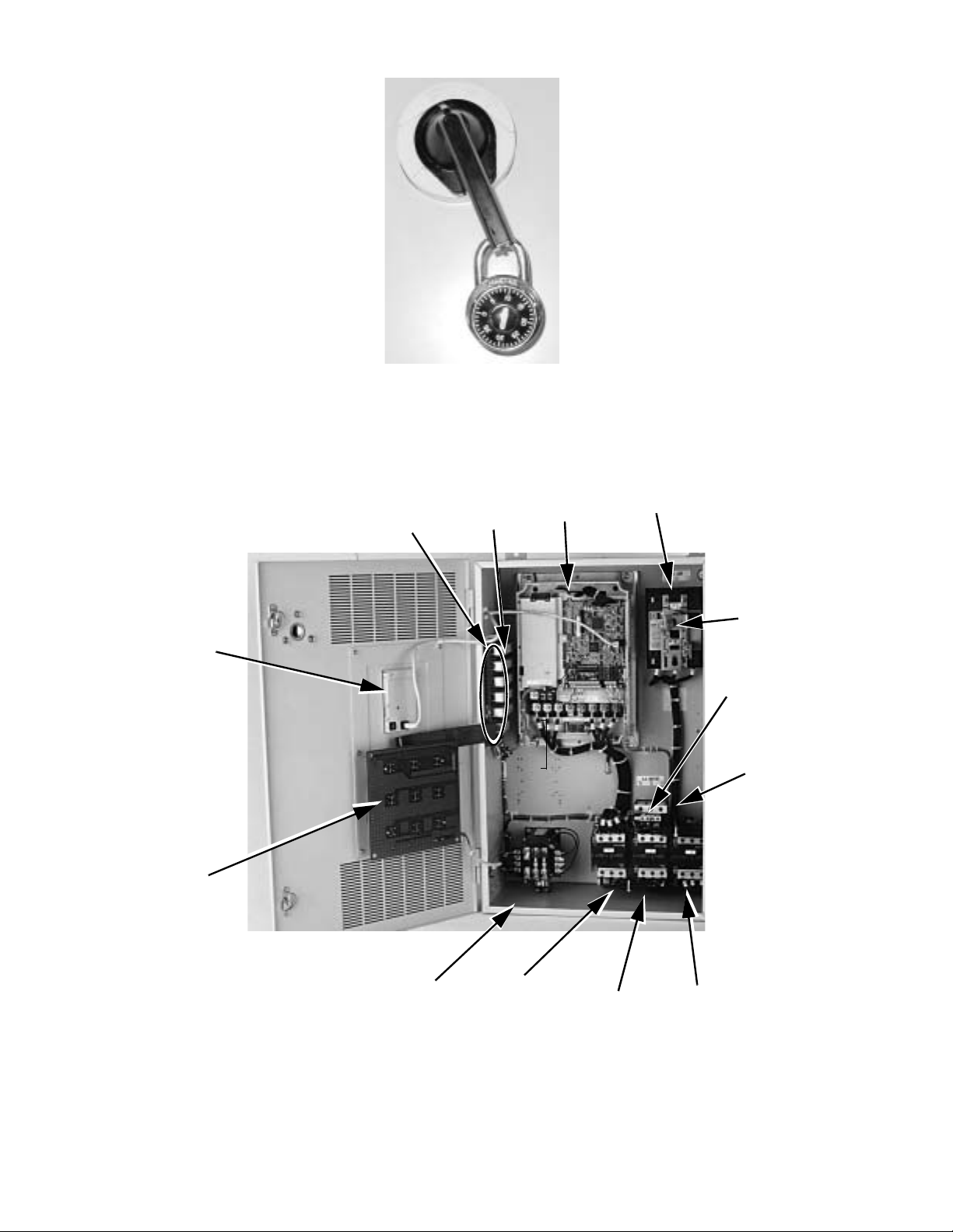
" MCP Motor Circuit Protector Circuit Breaker/Disconnect
Electrically located on the input power side of the Bypass unit, the MCP adjustable, instantaneous trip circuit breaker
provides protection from short circuits for the motor power cables. The Bypass three phase input power connection is made to the
input terminals of the MCP. The door mounted rotary operating mechanism is a convenient means of disconnecting the Bypass
unit from line power for equipment maintenance. The MCP must be in the OFF position in order to open the enclosure door.
Service and troubleshooting personnel are prov ided w ith a mean s to defeat this door interlock. The rotary handle provides trip
indication and can be padlocked in the OFF position.
CAUTION
Only qualified service
personnel should use
the defeator feature.
Defeator
Fig 1.5 MCP Handle Positions – RESET/LOCK, OFF, TRIP, ON Shown in the “ON” position
Physical Installation 1 - 12
Page 25
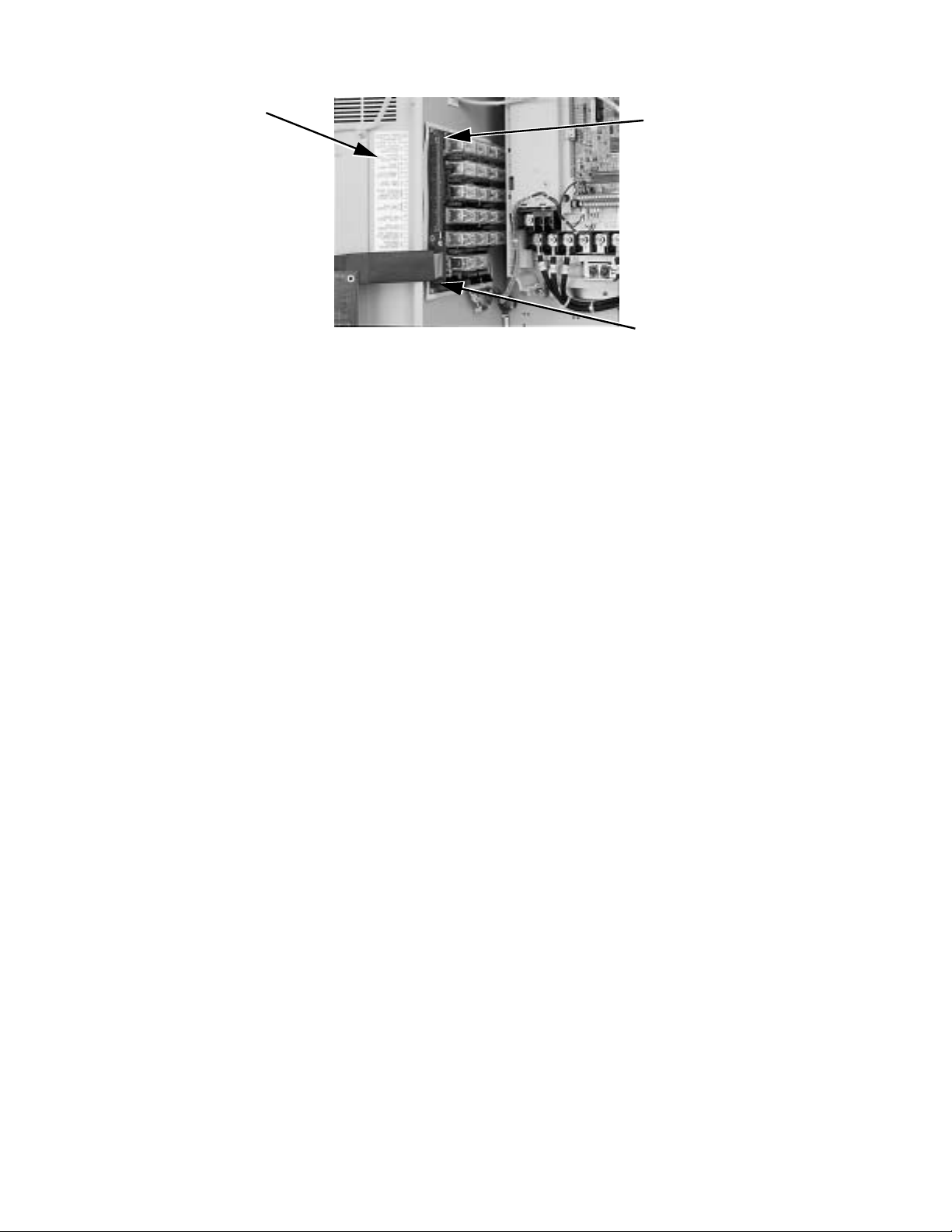
" Internal Bypass Panel
Fig 1.6 MCP Handle Positions – Shown OFF, With Padlock
Digital Operator
PCB A3
Customer Wiring
Terminal Strip (TB1)
PCB A2
Drive
Line
Connections
Motor Circuit
Protector
Load
Connections
Overload
Relay
Control Power
Transformer
Fig 1.7 Internal Bypass Panel
Input
Contactor
(K1)
Physical Installation 1 - 13
Bypass
Contactor
(K3)
Output
Contactor
(K2)
Page 26
TB1 Label Defining
Customer Control
Circuit Connection
Points
Fig 1.8 Control Terminal Strip
TB1 with Terminal Numbers
Printed on the PCB
Slide Switches for switch
selectable functions (Auto
Transfer, Remote Transfer and
Smoke Purge) are behind this
ribbon cable connector. See
Fig. 1.9 for details.
" Contactors
The Bypass is a “3 contactor Bypass” circuit employing IEC rated contactors in an electrically interlocked arrangement to
allow mutually exclusive operation in Drive or Bypass modes. To minimize enclosure space requirements, they are mounted in
a 3 contactor assembly.
The control logic and “soft start” characteristic of the Drive limit the Drive input and output contactors to motor FLA current
or less. For this reason, the Drive input and output contactors have lower current ratings than the Bypass contactor . The Bypas s
contactor is exposed to motor inrush current (LRA) when starting the motor across-the-line and therefore requires a higher
current rating.
" OverLoad Relay
The OverLoad Relay (OLR) is mounted to the contactor assembly or back panel (depending on rating), just above the Bypass
contactor (see Figure 1.7). Electrically on the output power side of the Bypass unit, the adjustable thermal OLR provides
overload protection for the motor in both the Drive and Bypass operating modes. The Bypass three phase output power
connection to the motor is made to the output terminals of the overload relay. The OLR is set up in the factory to be a manual
reset device, requiring operator attention if an overload trip-out is experienced.
" Control Power Transformer
A Control Power T ransf orme r (CPT) is provided to power the Bypass 120 VAC control circuit. The VA capacity is determ ined
by the control circuit and optional functions specified for the unit. 100 VA of extra transformer capacity for customer control
logic is provided in the standard unit and additional capacity is available as an “engineered” or “custom” option. The CPT
primary is fused in both legs, the secondary is fused when requi red by NEC (a bove 350 VA). One side of the transformer
secondary is grounded to the Bypass enclosure.
" Relay and Selector Switch Logic
Operating elements such as indicating lights and selector switches, as well as the control relay logic, have been incorporated
into a PCB assembly to eliminate the potential for loose wires after shipment and to control factory costs.
The operating elements are located on PCB A3, mounted to the insid e of th e enclosure door and ribbon cable connected to the
control relay logic PCB A2.
The control relay logic PCB A2 is mounted to the left hand side of the enclosure and contains the control circuit field wiring
terminal strip (TB1).
" Drive/Bypass logic interlocks explained
The Bypass 120 VAC relay logic circuit is in terconnected with the Drive multi-function digital input terminals and multifunction digital output terminals to allow a single customer interface to control both Drive and Bypass circuits. Some of these
terminals are therefore not available for other field use.
Physical Installation 1 - 14
Page 27

Drive Multi-function input terminals:
Ter minal S
Ter minal S
Ter minal S
receives the Drive run command from the 120 VAC relay logic circuit.
1
receives the Drive run enable signal from the 120 VAC relay logic circuit.
3
receives the Drive local/remote command from the 120 VAC relay logic circuit via the HAND/OFF/
5
AUTO and NORMAL/TEST selector switch.
Drive Multi-function output terminals:
Terminals M
and M2 are a normally open Drive run relay contact used to communicate the Drive operational mode
1
to the 120 VAC relay logic circuit.
Terminals M
and M4 are a normally open serial com. run status relay contact used to communicate the Drive
3
operational state to the 120 VAC relay logic circuit.
Terminals M
and MC are a normally open Drive fault relay co ntact used to commu nicate the Drive fault status to the
A
120 VAC relay logic circuit.
" PCB Jumpers explained
The S101 “Berg pin” jump er on the co ntrol relay logic PC B A2 is not for field use. It is employed only in the factory to enable
the 2 motor “OR” configured option. It is removed when this option is present and must be in place when this option is not part
of the unit specification (See Figure 1.9).
The S102 “Berg pin” jump er on the co ntrol relay logic PC B A2 is not for field use. It is employed only in the factory to enable
the Run/Stop Push Button (3 wire control) configured option. It is removed when this option is present and must be in place
when this option is not part of the unit specification (See Figure 1.9).
TB1 terminals 1 and 2 are jumpered (J1) as the unit is shipped from the factory. If a customer supplied series circuit of NC
safety devices is to be used, this jumper is removed and the safety circuit connected between terminals 1 and 2.
TB1 terminals 5 and 6 are jumpered (J2) as the unit is shipped from the factory. If a customer supplied Drive NO enabling
contacts are to be used (such as a damper end switch or occupied cycle timer), this jumper is removed and the enabling
contacts wired between terminals 5 and 6.
Physical Installation 1 - 15
Page 28
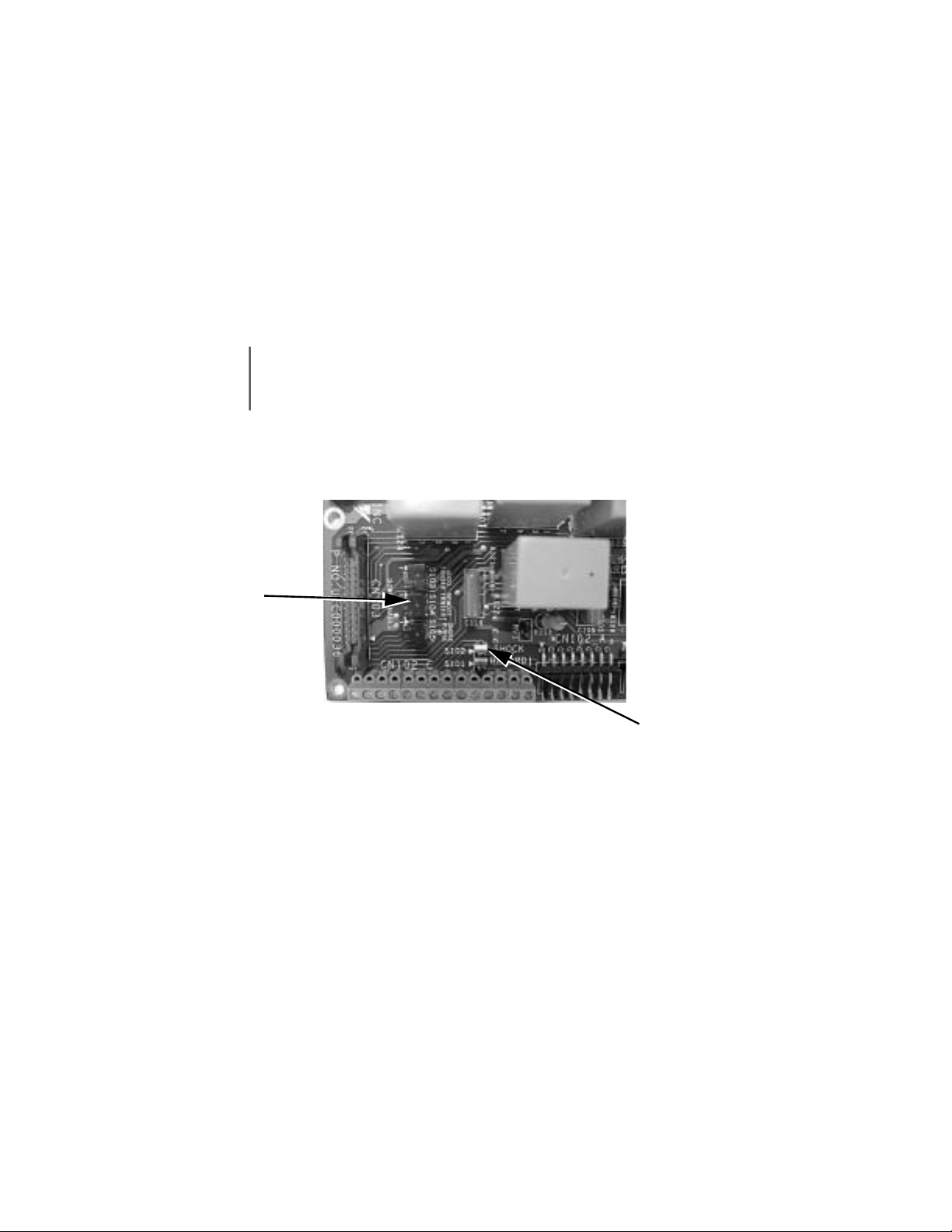
" Switch Selectable Functions:
The slide switches used to select these functions are located on the relay controller Printed Circuit Board (PCB) A2
(See Figure 1.9). The factory default is for these functions to be de-selected.
Smoke Purge: When enabled (switch S105) this function allows a contact closure, between terminals 17 and 18 o f
TB1, to transfer motor operation to bypass for a maximum capacity smoke control function. When in smoke purge
mode, during emergency fire/smoke situations, the motor overloads and safety interlock circuit are overridden to shift
the priority to protecting people rather than equipment.
Auto T ran sfer to B ypass: If enabled (switch S103), the P7 Bypass unit will automatically transfer the motor operation
from Drive to Bypass in the event of a Drive fault. When the Drive fault condition has cleared, this function is reset
by moving the H/O/A switch to the OFF position, waiting for the keypad to go blank, then switching back to the
DRIVE position.
Before selecting this function in fan applications, care must be taken to ensure that the duct-work is
IMPORTANT
Remote Transfer to Bypass: When selected (switch S104) this function allows a contact closure from a separate
source, between terminals 25 and 26 of TB1, to transfer motor operation from Drive mode to Bypass mode. This
remote tranfer to Bypass function overrides the DRIVE/BYPASS manual switch.
designed to handle the pressure resulting from full speed operation with the VAV terminal unit dampers at
minimum position or closed.
Slide Switches
PCB Jumpers
Fig 1.9 Printed Circuit Board A2
Physical Installation 1 - 16
Page 29
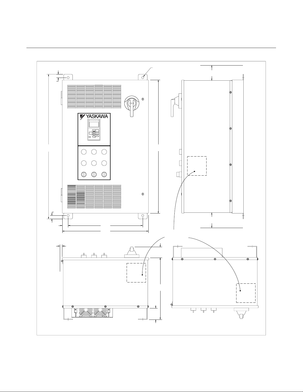
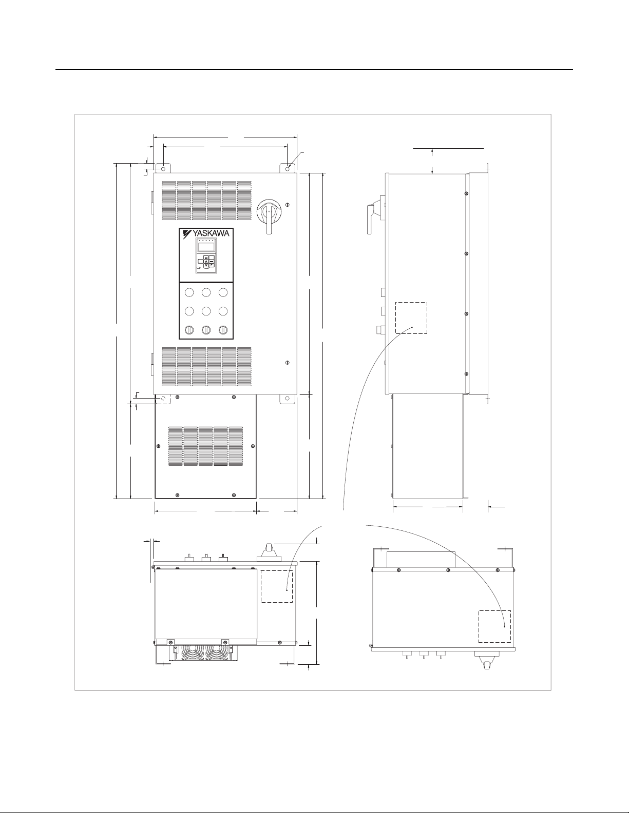
Exterior and Mounting Dimensions
! Bypass Unit 30 HP and Below, 480 VAC; 15 HP and Below, 208V/240V
Ø0.50(4PLS)
0.75
(19)
(Ø12.7)
FWD
SEQ
REV
REF
ALARM
AUTO
MENU
ESC
DATA
Monitor
ENTER
RESET
STOP
RUN
P7
MIN. 6
(152.4)
32.00
(812.8)
1.29
(32.8)
0.75
(19)
MIN. 1.50
(3.81)
BYPASS
RUN
MOTOR OL/
SAFETIES FAULT
TEST
CONTROL
DRIVE
POWER ON
RUN
SMOKE
DRIVE
PURGE
FAULT
NORMAL
OFF
AUTO
DRIVE
BYPASS
HAND
16.50
(419.1)
19.06
(484.1)
29.48
(748.8)
2.37
(60.2)
13.66
(347)
RECOMMENDED
CONDUIT
ENTRANCE AREA
TOP, BOTTOM
AND SIDE
MIN. 6
(152.4)
DIMENSIONS IN INCHES (MM), FOR REFERENCE ONLY
2.50
(63.5)
Fig 1.10 Enclosure 1 for up to 30HP, 480 VAC
NEMA 1 and NEMA 12 FVFF Enclosures
Physical Installation 1 - 17
TOP VIEW
Page 30
! Bypass Unit 30 HP and Below, 480 VAC; 15 HP and Below, 208V/240V
With Add-On Box
19.06
FWD
Monitor
BYPASS
(419.1)
REV
MENU
CONTROL
POWER ON
SMOKE
PURGE
16.50
SEQ
REF
AUTO
STOP
DRIVE
(484.1)
Ø0.50(4PLS)
(Ø12.7)
ALARM
ESC
DATA
ENTER
RESET
P7
DRIVE
RUN
DRIVE
FAULT
OFF
AUTO
HAND
29.48
(748.8)
43.35
(1,101.2)
MIN. 6
(152.4)
44.60
(1132.8)
32.00
(812.8)
(32.8)
0.75
(19)
1.29
SAFETIES FAULT
TEST
RUN
BYPASS
RUN
MOTOR OL/
NORMAL
12.60
(317.5)
(19)
0.75
MIN. 1.50
(3.81)
13.50
(342.9)
5.37
(136.4)
13.87
(3.81)
2.50
(63.5)
2.37
(60.2)
13.66
(347)
RECOMMENDED
CONDUIT
ENTRANCE AREA
TOP, BOTTOM
AND SIDE
9.1 3.375
(231.1)
TOP VIEW
(85.7)
DIMENSIONS IN INCHES (MM), FOR REFERENCE ONLY
Fig 1.11 Enclosure 1, with Options Extension, for up to 30HP, 480 VAC
NEMA 1 and NEMA 12 FVFF Enclosures
Physical Installation 1 - 18
Page 31

! Bypass Unit 40 HP to 100 HP, 480 VAC; 20 HP to 40 HP, 208V/240V
Ø0.50 (4PLS)
43.00
(1092.2)
0.75
(19)
MOTOR OL/
SAFETIES FAULT
TEST
(Ø12.7)
FWD
SEQ
REV
REF
ALARM
AUTO
MENU
ESC
DATA
Monitor
ENTER
RESET
STOP
RUN
P7
CONTROL
BYPASS
RUN
DRIVE
POWER ON
RUN
SMOKE
DRIVE
PURGE
FAULT
OFF
NORMAL
AUTO
DRIVE
BYPASS
HAND
40.48
(1028.2)
MIN. 6
(152.4)
0.75
(19)
1.32
(33.5)
MIN. 1.50
(3.81)
(584.2)
DIMENSIONS IN INCHES (MM), FOR REFERENCE ONLY
23.00
23.00
(584.2)
3.50
(88.9)
2.37
(60.2)
14.66
(372.4)
RECOMMENDED
CONDUIT
ENTRANCE AREA
TOP, BOTTOM
AND SIDE
Fig 1.12 Enclosure 2, for 40HP to 100HP, 480 VAC
NEMA 1 and NEMA 12 FVFF Enclosures
MIN. 6
(152.4)
TOP VIEW
Physical Installation 1 - 19
Page 32

! Bypass Unit 40 HP to 100 HP, 480 VAC; 20 HP to 40 HP, 208V/240V
With Add-On Box
25.63
(651)
MOTOR OL/
SAFETIES FAULT
TEST
23.00
(584.2)
FWD
SEQ
REV
REF
ALARM
AUTO
MENU
ESC
DATA
Monitor
ENTER
RESET
STOP
RUN
P7
CONTROL
BYPASS
DRIVE
POWER ON
RUN
RUN
SMOKE
DRIVE
PURGE
FAULT
OFF
NORMAL
AUTO
DRIVE
BYPASS
HAND
Ø0.50 (4PLS)
(Ø12.7)
40.48
(1028.2)
55.35
(1431.3)
MIN. 6
(152.4)
56.60
(1437.6)
1.32
(33.5)
43.00
(1092.2)
0.75
(19)
0.75
(19)
13.60
(345.4)
MIN. 1.50
(3.81)
DIMENSIONS IN INCHES (MM), FOR REFERENCE ONLY
Fig 1.13 Enclosure 2, with Options Extension, for up to 40HP to 75HP, 480 VAC
14.87
(377.7)
18.00
(457.2)
7.44
(189)
(60.2)
14.66
(372.4)
3.50
(88.9)
NEMA 1 and NEMA 12 FVFF Enclosures
2.37
RECOMMENDED
CONDUIT
ENTRANCE AREA
TOP, BOTTOM
AND SIDE
9.1 4.375
(231.1)
TOP VIEW
(111.1)
Physical Installation 1 - 20
Page 33

! Bypass Unit 125 HP to 250 HP, 480 VAC; 50 HP to 125 HP, 208V
THIS DIMENSION IS 23.50 IF
A MA FRAME CIRCUIT
BREAKER IS USED
EYEBOLTS ARE
REMOVABLE
15.00
(381)
CIRCUIT
P7
BREAKER
HANDLE
LOCATION
42.00
(1066.8)
1.70
(43.2)
DRIVE
HEATSINK
MIN. 10.00
(254)
84.00
(2133.6)
37.75
(958.8)
MIN. SPACE REQ'D TO OPEN DOOR
3.00
(76.2)
1.00
(25.4)
13.00
(330.2)
.62
(15.8)
(4 PLS)
1.00
(25.4)
1.38
(35.1)
FOR BOTTOM CONDUIT ENTRY, DUE TO POSSIBLE INTERFERENCE WITH OPTIONAL EQUIPMENT MOUNTED
INTERNALLY, VERIFY SPECIFIC REQUIREMENTS WITH THE FACTORY.
DIMENSIONS IN INCHES (MM), FOR REFERENCE ONLY
35.00
(889)
RECOMMENDED
CONDUIT
ENTRANCE AREA
TOP AND BOTTOM
35.50
(901.7)
20.00
(508)
Fig 1.14 Enclosure F1, for 125HP to 250HP, 480 VAC
NEMA 1 and NEMA FVFF 12 Enclosures
20.00
(508)
10.00
(254)
TOP VIEW
5.00
(127)
12.00
(304.8)
3.00
(76.2)
COVER PLATE
Physical Installation 1 - 21
Page 34

! Dimensions and Weights
Rated
Input
Voltage
208V
240V
230V
Continuous
Output
Current (Amps)
2.4 1/2 D002
3.5 3/4 D003
4.6 1 D004
7.5 2 D007
10.6 3 D010
16.7 5 D016
24.2 7.5 D024
30.8 10 D030
46.2 15 D046
59.4 20 D059
74.8 25 D074
88 30 D088
114 40 D114
143 50 D143
169 60 D169
211 75 D211
273 100 D273 1214
343 125 D343 1330
396 150 D396 1423
2.2 1/2 A002
3.2 3/4 A003
4.0 1 A004
6.8 2 A006
9.6 3 A009
15.2 5 A015
22 7.5 A022
28 10 A028
42 15 A042
54 20 A054
68 25 A068
80 30 A080
104 40 A104
130 50 A130
154 60 A154
192 75 A192
248 100 A248 1214
312 125 A312 1330
360 150 A360 1376
Nominal
(1)
HP
Bypass
_ _ _
Table 1.6 Bypass Dimensions and Weights
NEMA 1 and NEMA 12
Dimensions inches (mm)
_
Height
32.00
(812.8)
43.00
(1092.2)
84.00
(2133.6)
32.00
(812.8)
43.00
(1092.2)
84.00
(2133.6)
(2)
Width Depth
19.06
(484.1)
25.63
(651.0)
37.75
(958.9)
19.06
(484.1)
25.63
(651.0)
37.75
(958.9)
16.03
(407.2)
17.03
(432.6)
21.7
(551.2)
16.03
(407.2)
17.03
(432.6)
21.7
(551.2)
Mounting
Dimensions
30.5 x 16.5
(774.7) x
41.5 x 23.0
(1054.1 x
Floor Mount
35.0 x 13.0
(889 x 330.0)
30.5 x 16.5
(774.7) x
41.5 x 23.0
(1054.1 x
Floor Mount
35.0 x 13.0
(889 x 330.0)
Wall
H x W
(419.1)
584.2)
W x D
(419.1)
584.2)
W x D
Drawing
Drawing
Number
S-5542 S-5543
S-5544 S-5545
S-5550 N/A
S-5542 S-5543
S-5544 S-5545
S-5550 N/A
Number
(w/ Add-on
Box)
Weight
(4)
(3)
(lbs)
115
127
208
221
847
943
115
127
208
221
847
943
(1) Horsepower rating is based on standard NEMA B 4-pole motor design
(2) Height dimension includes the mounting screw tabs.
(3) Add-on box adds 13.6 inches to Height dimen sion and 91 lbs. Max. to total
(4) Data represents the total weight of the Drive with all possible standard options, not shipping weigh t.
Physical Installation 1 - 22
Page 35

Rated
Input
Voltage
480V
Table 1.6 Bypass Dimensions and Weights (Continued)
Continuous
Output
Current (Amps)
Nominal
(1)
HP
Bypass
_ _ _
NEMA 1 and NEMA 12
Dimensions inches (mm)
_
Height
(2)
Width Depth
Wall
Mounting
Dimensions
H x W
Drawing
Number
1.1 1/2 B001
1.6 3/4
2.1 1 B002
3.4 2 B003
4.8 3 B004
7.6 5 B007
11 7.5 B011
32.00
(812.8)
19.06
(484.1)
16.03
(407.2)
30.5 x 16.5
(774.7) x
(419.1)
S-5542 S-5543
14 10 B014
21 15 B021
27 20 B027
40 30 B040
52 40 B052
65 50 B065
77 60 B077
96 75 B096
43.00
(1092.2)
25.63
(651.0)
17.03
(432.6)
41.5 x 23.0
(1054.1 x
584.2)
S-5544 S-5545
124 100 B124
156 125 B156
180 150 B180
240 200 B240 1240
84.00
(2133.6)
37.75
(958.9)
21.7
(551.2)
302 250 B302 1352
Floor Mount
W x D
35.0 x 13.0
(889 x 330.0)
S-5550 N/A
Drawing
Number
(w/ Add-on
Box)
Weight
(4)
(3)
(lbs)
115
127
14234 25 B034
203
232
241
943
(1) Horsepower r ating is based on standar d NEMA B 4-pole motor design
(2) Height dimension includes the mounting screw tabs.
(3) Add-on box adds 13.6 inches to Height dimension and 91 lbs. Max. to total
(4) Data represents the total weight of the drive with all possible standard options, not shipping weight.
Physical Installation 1 - 23
Page 36

Checking and Controlling Installation Site
Install the Bypass unit as described below and maintain the specified operating condition s.
! Installation Site
Location of the Bypass unit is important to achieving proper performance and design operating life. Install the Bypass unit as
close as possible to the motor. The NEMA type 1 & 12 enclosed units should be installed in an area where it will be protected
from: Direct sunlight, rain or moisture, corrosive gasses or liquids, vibration and dust or metallic particles. The ambient air
available for cooling the unit should be 104° F (40° C) or less.
Wall mount units require a minimum 6 inch clearance above and below, to achieve adequate heat sink cooling. When the addon box is employed for optional equipment, no additional bottom clearance is required.
No side clearance is required for cooling because the cooling air flow is in and out of th e enclo sure d oor at the front surface of
the unit (do not block the air flow louver s). Clearance fo r the open in g swi ng of the encl os ur e door should be con sider ed when
placing these units. The door is hinged on the left and must open through at least a 90 degree swing with a 120 to 180 degree
swing being preferable (minimum clearance is 1.5”).
Floor mounted units require a minimum clearance of 10 inches above the enclosure to allow for air flow over the heat sink
fins.
Install the Bypass unit under the following conditions in UL pollution degree 1 & 2 environments. This excludes wet locations
where surfaces may become conductive due to moisture and contaminant loading.
Table 1.7 Installation Site
Type Ambient Operating Temperature Humidity Plenum Rated
NEMA Type 1 & 12 14 to 104°F (-10-to-+ 40°C) 95%-RH-or-less-(no-condensation) Yes
Observe the following precautions when mounting the Bypass unit.
• Install the Bypass unit in a clean location that is free from oil mist and dust.
• Install the Bypass unit in an environment w here metal shavings, oil, water, or other foreign matter will not get into th e
Bypass enclosure.
• Install the Bypass unit in a location free from radioactive materials.
• Install the Bypass unit in a location free from harmful gasses and liquids.
• Install the Bypass unit in a location without excessive vibration.
• Install the Bypass unit in a location free from chlorides.
• Install the Bypass unit in a location not in direct sunlight.
• Install the Bypass unit on a non-combustible surface.
Physical Installation 1 - 24
Page 37

! Controlling the Ambient Temperature
To enhance the reliability of operation, the By pass unit should be installed in an environment free from extreme temperature
variations. Do not store this Technical Manual or any other documents on the top surface of the Bypass unit, they may cover
the heat sink cooling air discharge opening and cause the unit to overheat.
If the Bypass unit is installed in an enclosure (such as an electrical control box in an air handling unit), use a cooling fan or air
conditioner to maintain the Bypass unit internal air temperature below 113°F (45°C).
! Protecting the Bypass Unit from Foreign Matter
During Bypass unit installation an d project construction, it is possible to hav e foreign matter, such as metal shavings or wir e
clippings, fall inside the Bypass unit. T o preven t foreign matter from falling into the Bypass unit, place a temporary cover over
the unit.
Always remove the temporary cover from the Bypass u nit before star t-up. Ot herwise, ventilat ion will b e reduced, causi ng the
Bypass unit to overheat.
Physical Installation 1 - 25
Page 38

! Installation Orientation and Enclosure Considerations
Install the Bypass unit vertically so as not to reduce the cooling efficiency . When installing the Bypas s unit, always provide the
recommended installation clearances to allow normal heat dissipation.
When preparing to mount the unit, lift it by the base (or lifting rings when provided), never by th e e nclosure door. For effective
cooling and proper maintena nce, the wall mounte d units must be installed on a flat non-fla mmable vertica l surface using four
mounting screws.
To mount units employing the add-on box, a hex head mounting screw and socket wrench will be required for the lower left
mounting hole location. See Figure 1.15.
For all units, the MCP handle should be in the OFF position to open the enclosure door. The wall mount units have two full turn
fasteners, CCW to open, that require a flat blade screwdriver to open the enclosure door.
Mounting
Holes
Mounting
Holes
Fig 1.15 Add-on Options Box
Physical Installation 1 - 26
Page 39

Chapter 2
Electrical Installation
This chapter describes wiring and the electrical installation process for a Drive and
Bypass unit.
Termination Configuration - Power Wiring .....................................2
Field Wiring, Pressure Wire Connector, Wire Type, Range
and Tightnening Torque Specifications .......................... ...........3
Cable Length between Drive and Motor ....................................4
Grounding ................................................................................. 5
Wire Routing ........................... ............................. ............... ......6
Drive Main Circuit Configurations 208-240 VAC .......................7
Drive Main Circuit Configurations 480 VAC ..............................8
Control Wiring ................................................................................9
Bypass Field Control Wire Landing .................................. .. .......9
Annunciation Contacts ..............................................................9
Damper Control Circuit ............................................................ 10
Customer Supplied Run/Stop circuit: ......................................10
Safety Interlock Circuit: ........................................................... 10
Customer Supplied Interlock Circuit
(Drive and Bypass enable input): ............................................10
Switch Selectable Functions: ..................................................10
Bypass Relay Controller PCB ........... ...................... ................ 11
Drive Speed Control Circuit Wiring .......................................... 12
Drive Terminal Block Configuration ......................................... 13
Wiring Chec ks ......................................... ............................ ....14
Control Circuit Wiring Precautions ..........................................14
Bypass Control Circuit Terminal Functions .............................15
DIP Switch S1 ......................................................................... 16
Shunt Connector CN15 ...........................................................17
Field Wiring D ia g ra m ........................ ................ ............... ........ 18
Wiring Diagram ...................... .. ............... ............................. ........20
Logic Diagram ....................... .. .....................................................22
Electrical Installation 2 - 1
Page 40

Termination Configuration - Power Wiring
The Circuit Breaker/MCP is located in the upper right hand side of the Bypass unit. The Bypass three phase input power
connection is made to the input terminals of the MCP. See Figure 2.1 and 2.2 for representative examples.
Motor
Input Power
Ground Lug
Fig 2.1 Typical Input Power Connection, Fig. 2.2 Typical Input and Output Power
Wall Mount Unit Connections, Floor Mount Unit
The OverLoad Relay (OLR) is mounted to the contactor assembly or back panel (depending on rating), just above the bypass
contactor. The Bypass three phase output power connection to the motor is made to the output terminals of the OverLoad
Relay. See Figure 2.3 for representative examples.
Motor Connections
Connections
Ground Lug
Motor Connections
Input Power
Overload Relay
Fig 2.3 Typical Output Power Connection, Wall Mount Units
Electrical Installation 2 - 2
Page 41

! Field Wiring, Pressure Wire Connector, Wire Type, Range and Tightnening
Torque Specifications
BYPASS MODEL NO.
BASE NUMBER
_ _ _ _ -XXXX
208V
A002
D002
A003
D003
A004
D004
D007
A006
D010
A009
D016
A015
D024
A022
D030
A028
D046
A042
D059
A054
A068
D074
A080
D088
A104
D114
A130
D143
A154
D169
A192
D211
A248
D273
D343
A312
D396
A360
BYPASS MODEL NO.
BASE NUMBER
_ _ _ _ -XXXX
208V 480V
240V
A002
D002
A003
D003
A004
D004
A006
D007
A009
D010
A015
D016
A022
D024
A028
D030
A042
D046
A054
D059
A068
D074
A080
D088
A104
A130
D114
D143
A154
D169
A192
D211
A248
D273
A312
A360
D343
D396
The fourth underscore position in these model numbers codes for the enclosure type: V = NEMA1, B = NEMA12 FVFF.
*
FOR 0 TO 100 AMPS, USE 60 -75 C COPPER WIRE, AND ABOVE 100 AMPS, USE 75 C COPPER WIRE.
MFG.
* *
PART
NUMBER
480V240V
B001
FAL36003
B002
FAL36007
B003
B004
B007
FAL36015
B011
B014
FAL36030
B021
FAL36050
B027
B034
B040
FAL36100
B052
B065
B077
B096
KAL36150
B124
KAL36250
B156
B180
B240
LAL36400
B302
B361
MAL36600
B414
MAL36800
B477
B515
B590
MFG.
PART
*
NUMBER
LR2 D13
B001
B002
LR2 D15
B003
B004
LR2 D15
B007
B011
B014
LR2 D15
B021
LR2 D25
B027
LR2 D35
B034
B040
LR2 D35
LR2 D35
B052
LR2 D35
LR2 D35
B065
LR2 D35
B077
LR2 D3563
B096
LR9 F5567
LR9 F5569
B124
LR9 F5569
LR9 F5569
B156
LR9 F5571
LR9 F5571
B180
B240
LR9 F7575
LR9 F7575
B302
LR9 F7579
LR9 F7579
B361
LR9 F7579
B414
LR9 F7581
B477
LR9 F7581
B515
LR9 F7581
B590
CUSTOMER A.C. LINE WIRING
CIRCUIT BREAKER
CURRENT
RATING
(AMPS)
3
7
15
30
50
100
150
250
400
600
800
STANDARD BYPASS OVERLOAD RELAY OR, WITH OPTION D A.C. CONTACTORSOR, WITH OPTION A OVERLOAD RELAYS
WIRE SIZE
6 - 300 kcmil
6 - 300 kcmil 275
2 x (6-300 kcmil)
2 x (6-300 kcmil)
2 x (6-300 kcmil) 2 x 500
2 x (6-300 kcmil)
3 x (6-300 kcmil)
3 x (6-300 kcmil) 3 x 500
3 x (6-300 kcmil)
WIRE SIZE
RANGE
(AWG)
14 - 4
14 - 4
14 - 4
12 - 4
12 - 1/0
12 - 1/0
4 - 350 kcmil
4 - 350 kcmil
1 x (1-600 kcmil)
2 x (1-250 kcmil) 2 x 375
(1-3) x (3/0-500 kcmil)
(1-3) x (3/0-500 kcmil)
RANGE
(AWG)
18 - 10
18 - 10
18 - 10
18 - 10
14 - 6
10 - 1/0
10 - 1/0
10 - 1/0 75
10 - 1/0
10 - 1/0 75
10 - 1/0
10 - 1/0
6 - 3/0
6 - 3/0
6 - 3/0 200
6 - 3/0
TIGHTENING
TORQUE
(LB.-IN.)
15
15
15
15
15
75
75
75
75
100
200
200
200
275
2 x 500
2 x 500
2 x 5002 x (6-300 kcmil)
2 x 500
3 x 500
3 x 500
TIGHTENING
TORQUE
(LB.-IN.)
35
35
35
35
80
80
250
250
375
(1-3) x 300
(1-3) x 300
CUSTOMER A.C. MOTOR WIRING
MFG.
PART
NUMBER
LR2 D13
LR2 D15
LR2 D15
LR2 D15
LR2 D15
LR2 D15
LR2 D25
LR2 D25
LR2 D35
LR2 D35
LR2 D35
LR2 D35
LR2 D35
LR9 F5567
LR9 F5569
LR9 F5569
LR9 F5569
LR9 F5571
LR9 F5571
LR9 F7575
LR9 F7575
WIRE SIZE
RANGE
(AWG)
18 - 10
18 - 10
18 - 10
18 - 10 15
18 - 10
18 - 10 15
14 - 6
14 - 6 15
10 - 1/0
10 - 1/0 75
10 - 1/0
10 - 1/0 75
10 - 1/0
6 - 3/0
6 - 3/0
6 - 3/0
6 - 3/0
6 - 300 kcmil
6 - 300 kcmil
2 x (6-300 kcmil)
2 x (6-300 kcmil) 2 x 500
BYPASS MODEL NO.
BASE NUMBER
_ _ _ _ -XXXX
240V 480V208V
D002
A002
D003
A003
D004
A004
D007
A006
D010
A009
D016
A015
D024
A022
D030
A028
D046
A042
D059
A054
A068
D074
A080
D088
A104
D114
D143
A130
D169
A154
D211
A192
D273
A248
D343
A312
D396
A360
TIGHTENING
B001
B002
B003
B004
B007
B011
B014
B021
B027
B034
B040
B052
B065
B077
B096
B124
B156
B180
B240
B302
B361
B414
B477
B515
B590
TORQUE
(LB.-IN.)
15
15
15
15
15
75
75
75
200
200
200
200
275
275
2 x 500
CUSTOMER EARTH GROUND WIRING
MFG.
PART
NUMBER
LC1 D09
LC1 D18
LC1 D25
LC1 D32
LC1 D40
LC1 D50
LC1 D65
LC1 D80
LC1 D115
LC1 D150
LC1 F185
LC1 F265
LC1 F330
LC1 F400
LC1 F500
LC1 F630
GROUND LUG
WIRE SIZE
RANGE
(AWG)
14 - 10 35
840
6 - 4 45
WIRE SIZE
RANGE
(AWG)
18 - 10
18 - 8
18 - 8
14 - 6
10 - 3
10 - 3
10 - 3
10 - 2
8 - 250 kcmil
8 - 250 kcmil
6 - 3/0
6 - 300 kcmil
6 - 300 kcmil
4 - 500 kcmil
2 x (2-600 kcmil)
3 x (2-600 kcmil)
TIGHTENING
TORQUE
(LB.-IN.)
1204 - 2/0
TIGHTENING
TORQUE
(LB.-IN.)
100
100
100
200
275
275
500
2 x 500
3 x 500
7
15
15
20
45
45
45
IMPORTANT
WARNING
Determine the wire size for the main circuit so that line voltage drop is within 2% of the rated voltage. Line
voltage drop is calculated as follows:
Line voltage drop(V) = √3 x wire resistance (Ω/km) x wire length (m) x current (A) x 10
-3
Prior to removing any protective cover or wiring any part of the Drive, remove all power sources, including
main input power and control circuit power. Wait a minimum of 5 minutes after power removal, before
removing any cover. The charge lamp located within the Drive should be off prior to working inside. Even if
the charge lamp is off, one must measure the AC input, output, and DC Bus potential to insure safe levels
prior to resuming work. Failure to adhere to this warning may result in personal injury or death.
Electrical Installation 2 - 3
Page 42

! Cable Length between Drive and Motor
The Bypass unit should be installed as close as possible to the motor to minimize the len gth of load si de power cable needed
between the Drive and the motor. If the cable between the Drive and the motor is long, the high-frequency leakage current will
increase, causing the Drive output current to increase as well. This may affect peripheral devices. To prevent this, reduce cable
length, or if necessary, adjust the carrier frequency (set in C6-02) as shown in Table 2.1.
The line side power cables, load side power cables and the control wiring should all be run in a separate conduit. C areful
attention to this recommended design practice will avoid many potential motor and Drive related pro blems.
Table 2.1 Motor Cable Length vs. Carrier Frequency (C6-02)
Motor Cable Length 164 ft. (50m) maximum 328 ft. (100m) maximum More than 328 ft.(100m)
Carrier Frequency 15kHz maximum 10kHz maximum 5kHz maximum
(See the limitations on carrier frequency, based on Drive capacity and model number in Appendix B).
Electrical Installation 2 - 4
Page 43

! Grounding
" Drive and Motor Ground Wire Landing
The Drive ground lug (terminal ) is connected to the enclosure. The enclosure ground lug must be connected to earth
ground. See Figures 2.1 and 2.2.
The Drive has a second ground lug to accept the motor ground lead. See Figure 2.9.
" Ground Wiring Precautions
Observe the following precautions when connecting the ground wire:
1. 208-240 VAC Drives should have a ground connection with resistance of less than 100 Ω..
2. 480 VAC Drives should have a ground connection with resistance of less than 10 Ω..
3. Do not share the ground wire with other devices, such as large-current electrical equipment.
4. Always use a ground wire that complies with technical standards on electrical equipment and minimize the length of the
ground wire. Leakage current flows through the Drive. Therefore, if the distance between the ground rod and the ground
terminal is too long, potential on the ground terminal of the Drive will become unstable.
5. When using more than one Drive, be careful not to loop the ground wire.
OK
For grounding connection to earth ground see Figures 2.1 and 2.2.
NO
OK
Fig 2.4 Ground Wiring Examples
NO
" Control Circuit Ground Terminals
The removable Drive control terminal card provides two ground terminals (marked TB3 and TB4) to accept the control wire
shield connection. The control wire shield should be connected on this end only, the opposite end should be isolated with
electrical tape.
IMPORT ANT
Grounding of the Bypass enclosure and motor is required for proper system operation.
Electrical Installation 2 - 5
Page 44

! Wire Routing
The following Figures indicate suggested wire entry and bending areas for representative wall mount enclosures.
Control
circuit
wiring
Motor
connection
Input
power
Control
circuit
wiring
Motor
connection
Typical Enclosure 2 Typical Enclosure 2
Fig 2.5 Wall Mount Enclosures
Input
power
Electrical Installation 2 - 6
Page 45

! Drive Main Circuit Configurations 208-240 VAC
The main circuit configurations of the Drive are shown in Tables 2.2 and 2.3.
Table 2.2 Drive Main Circuit Configurations
208-240 VAC
Note
1
CIMR-_ _ _ 20P4 to 2018
{
(1/2 Hp to 25 Hp)
Notes
1 & 3
{
CIMR-_ _ _ 2022 and 2030
(30 Hp to 40 Hp)
Power
supply
Control
circuits
Control
circuits
---
Power
supply
Control
circuits
Power
supply
CIMR-_ _ _ 2037 to 2110
(50 Hp to 150 Hp)
Notes
1 & 3
{
Note1. Input fuses or molded case circuit breakers are required for proper branch circuit protection for all Drives. Failure
to use recommended fuses/circuit breakers (See Appendix E) may result in damag e to the wiring, Drive and/or
personal injury.
2. Control power is supplied internally from the main circuit DC power supply for all Drives.
3. Consult your Yaska wa repres enta tive befo re using 12 -pu lse rectifica tio n.
Electrical Installation 2 - 7
Page 46

! P7 Drive Main Circuit Configurations 480 VAC
CIMR
4030
Table 2.3 Drive Main Circuit Configurations
480 VAC
Note
1
CIMR-_ _ _ 40P4 to 4018
{
(1/2 Hp to 30 Hp)
Notes
1 & 3
{
-_ _ _
(40 Hp to 100 Hp)
to 4055
3
Power
supply
Control
circuits
Control
circuits
---
Power
supply
Control
circuits
Power
supply
CIMR-_ _ _ 4075 to 4160 and CIMR-_ _ _ 4185 to 4300
Notes
1 & 3
{
Note1. Input fuses or molded case circuit breakers are required for proper branch circuit protection for all Drives. Failure
to use recommended fuses/circuit breakers (See Appendix E) may result in damag e to th e wiring, Drive and/or
personal injury.
2. Control power is supplied internally from the main circuit DC power supply for all Drives.
3. Consult your Yaska wa repres enta tive befo re using 12 -pu lse rectifica tio n.
(125 Hp to 500 Hp)
Electrical Installation 2 - 8
Page 47

Control Wiring
! Bypass Field Control Wire Landing
The Bypass field control wiring is terminated on the relay control PCB A2, Terminal block TB1. The terminal designations are
labeled on the door, adjacent to PCB A2 (see Figure 2.6). Route the control wiring as shown in Figure 2.5.
TB1 terminals 1 and 2 are jumpered (J1) as the unit is shipped from the factory. If a customer supplied series circuit of NC
safety devices is to be used, this jumper is removed and the safety circuit connected between terminals 1 and 2.
TB1 terminals 5 and 6 are jumpered (J2) as the unit is shipped from the factory. If customer supplied Drive NO enabling contacts (open = Drive disabled, closed = Drive enabled) are to be used (such as a damper end switch or occupied cycle timer),
this jumper is removed and the enabling contacts wired between terminals 5 and 6.
Fig 2.6 TB1 Control Terminal Locations, All Models
! Annunciation Contacts
Contacts for customer use are provided and wired to TB1 as follows for use as annunciators of Bypass unit operation. All
are 1 amp at 120 VAC contacts.
Table 2.4 Annunciation Contacts
Function Type TB1 Terminals
Motor OL/Safeties Fault Form C 14-15-16
Bypass Run Form A 9-10
Drive Run Form A 7-8
Drive Fault Form C 11-12-13
Electrical Installation 2 - 9
Page 48

! Damper Control Circuit
TB1 terminals 19 and 20 are provided to power a customer supplied 120 VAC relay, electric actuator or electro-pneumatic
solenoid air valve employed to control a pneumatic damper actuator, typically for outdoor air intake damper interlock. The
power rating of the conn ected dev i ce sh ou ld be no m ore th an 4 0 VA continuou s and 70 VA inrush. An off command (f rom the
H/O/A switch) or a safety device trip-out will immediately de-energize these terminals. At the same time the Drive will begin
the ramp to stop process (in Drive mode with the default stopping method). In some air handling unit applications operation
during the ramp to stop time with the dampers closed may be problem a tic. Over p ress urization of ducts or tri p-o ut o n high DC
bus voltage, due to overhauling of the load by other fans in the system, are possible outcomes. One solution is to reprogram the
stopping method in parameter b1-03 to “coast to stop” elimin ating the potential for both of these problems.
! Customer Supplied Run/Stop circuit:
A control terminal block position (TB1, terminals 3 and 4) is provided to connect the Normally Open (NO) Run/Stop contact
from a separate source or other remote controller for auto mode control.
There must be continuity between these terminals in order for the motor to run.
! Safety Interlock Circuit:
A control terminal block position (TB1, terminals 1 and 2) is provided to connect the series circuit of Normally Closed (NC)
safety devices such as: freeze up thermostats, smoke/fire sensors, high pressure limits, temperature limits or vibration
detectors.
There must be continuity between these terminals in order for the motor to run.
! Customer Supplied Interlock Circuit (Drive and Bypass enable input):
A control terminal block position (TB1, terminals 5 and 6) is provided to connect Normally Open (NO) enabling contacts such
as: damper end switches or occupied cycle timers.
There must be continuity between these terminals in order for the motor to run.
! Switch Selectable Functions:
The slide switches used to select these functions are located on the relay controller Printed Circuit Board (PCB) A2
(See Figure 1.9). The factory default is for these functions to be de-selected.
Smoke Purge: When enabled (switch S105) this function allows a contact closure, between terminals 17 and 18 of TB1, to
transfer motor operation to bypass for a maximum capacity smoke control function. When in smoke purge mode, during
emergency fire/smoke situations, the motor overloads and safety interlock circuit are overridde n to sh ift the priority to
protecting people rather than equipment.
Remote Transfer to Bypass: When selected (switch S104) this function allows a contact closure from a separate source,
between terminals 25 and 26 of TB1, to transfer motor operation from Drive mode to bypass mode. This remote tranfer to
bypass function overrides the Drive/Bypass manual switch.
Electrical Installation 2 - 10
Page 49

! Bypass Relay Controller PCB
TB1
ON PCB A2
26
25
24
23
22
21
(L1)
20
19
18
17
16
15
14
13
12
11
10
9
8
7
6
5
4
3
2
1
Fig 2.7 Bypass Control Circuit Inputs and Outputs
Customer provided contact closure inputs must have a minimum rating of 0.1 amp at 120 VAC.
Electrical Installation 2 - 11
Page 50

! Drive Speed Control Circuit Wiring
The auto mode speed reference (speed command) field wiring connection is made directly to Drive terminals A2 (signal
positive), AC (signal common) and G (shield). Keep this lead length as short as possible to maint a in signal q uality. Insulated
twisted shielded pair wire (2 conductor # 18 ga, Belden 8760 or equivalent) is required. Do not run these wires in the same
conduits as other AC power or con trol wires . The shield mu st be connect ed on this end on ly, stub and isolate the other end. The
signal employed is 4 to 20 mA with parameter H3-08 set for “2: 4 - 20 mA”. For 0 to 10 VDC, parameter H3-08 is set for
“0: 0 - 10 VDC” and the P7 control board DIP switch S1-2 must be in the OFF position. (See Figure 2.11)
For remote operation, keep the length of the control wiring to 50 m or less. Separate the control wiring from high-power lines
(input power, motor leads or relay sequence circuits) to reduce induction from peripheral devices.
When setting speed commands from an external speed potentiometer (and not from a Digital Operator), use shielded twisted-
pair wires and ground the shield to terminal E(G), as shown in Figure 2.8. Terminal numbers and wire sizes are shown in
T able 2.5.
Shield terminal
E (G)
External
frequency
reference
0 to +10 V
Fig 2.8 Analog Input Terminal Configuration on Drive
Speed setting power supply, +15 V 20 mA
Master speed reference, 0 to +10 V (20 kΩ)
Master speed reference, 4 to 20 mA (250 Ω)/0 to +10 V (20 kΩ)
P = Wire Pair
Electrical Installation 2 - 12
Page 51

! Drive Terminal Block Configuration
The wiring terminals are shown in Figure 2.9.
AC MP
-V
+V
A1
SCS+A2
Control circuit terminals
SN M6
S1
E(G) E(G)
FM
S5
S4SPS7 M4
S3
R- M5
R+RP
AC MA
AMS6
M3S2 S-
IG
AC
MCMB
M2
M1
Main circuit terminals
Charge indicator
Control circuit terminals
Main circuit terminals
Ground terminal
Models CIMR-_ _ _2018 (25 HP, 208V)/
4018 (30 HP, 480V) and smaller
AC MP
-VIGR- M5FMR+RP
+V
A1
SCS+A2M2SN M6
S1
E(G) E(G)
AC MA
AMS6
S5
S4SPS7 M4
S3
AC
MCMB
M3S2 S-
M1
Ground terminal
Charge indicator
Ground terminal
Ground terminal
Models CIMR-_ _ _2022 (30 HP, 208V)/
4030 (40 HP, 480V) and larger
Fig 2.9 Drive Terminal Configurati on
Electrical Installation 2 - 13
Page 52

Terminals
DRIVE
TERMINALS:
FM, AC, AM, SC, SN,
SP, A1, A2, +V, S1, S2,
S3, S4, S5, S6, S7, MA,
MB, MC, M1, M2 , M3,
M4, MP, R+, R-, S+,
S-, IG
TB1 ON PCB A2
TERMINALS:
TB1-1 through TB1-26
Table 2.5 Te rminal Numbers and Wire Sizes (Same for all Bypass Units)
Terminal
Screws
Phoenix
type *3
Tightening
Torque
lb.-in.
(N•m)
4.2 to 5.3
(0.5 to 0.6)
Possible
Wire Sizes
AWG
(mm
Stranded
wire:
26 to 16
(0.14 to 1.5)
2
)
Recommended
Wire Size
AWG
2
(mm
)
18
(0.75)
• Shielded, twisted-pair wire
• Shielded, polyethylene -c ov er e d ,
vinyl sheath cable
Wire Type
*1
E(G) M3.5
*1.Us e shielded twisted-p air cables to input an external speed command.
*2. We recommend using straight solderless te rminals on digital inputs to simplify wiring and improve reliability.
*3.We recommend using a thin-slot screwdriver with a 3.5 mm blade width.
7.0 to 8.8
(0.8 to 1.0)
20 to 14
(0.5 to 2
*2
)
12
(1.25)
! Wiring Checks
After all wiring is completed, perform the following checks:
1. Is all wiring correct?
2. Have all wire clippings, screws or other foreign material been removed from the Drive and Bypass enclosure?
3. Are all terminal screws tight?
! Control Circuit Wiring Precautions
Observe the following precautions when wiring control circuits:
1. Separate control wiring from power/motor wiring and other high-power lines.
2. Separate wiring for control circuit terminals for digital outputs from wiring to other control circuit terminals.
3. If using an optional external power supply, it should be a UL Listed Class 2 power supply source.
4. Use twisted-pair or shielded twisted-pair cables for control circuits to prevent operating faults. Prepare cable ends as
shown in Figure 2.10.
5. Connect the shield wire to terminal E(G).
6. Insulate the shield with tape to prevent contact with other signal lines and equipment.
Shield sheath
Connect to shield sheath
terminal E(G) at Drive
Fig 2.10 Preparing the Ends of Shielded Twisted-Pair Cables
Insulate with tape
Insulation
Do not connect here.
Electrical Installation 2 - 14
Page 53

! Bypass Control Circuit Terminal Functions
The functions of the control circuit terminals are shown in Table 2.6.
Table 2.6 Bypass Control Circuit Terminals
Type No. Signal Name Function S ign al Lev el
Digital
input
signals
Analog
input
signals
(Drive)
TB1-3
TB1-4
TB1-1
TB1-2
TB1-5
TB1-6
TB1-17
TB1-18
TB1-23
TB1-24
TB1-25
TB1-26
+V +15 VDC power output +15 VDC power supply for analog Transmitters
A1 Analog Input or Speed Command 0 to +10 VDC/100% 0 to +10 V(20 kΩ)
A2 Multi-function analog input
AC Analog input common – –
E(G)
Auto Mode run/stop command Run when CLOSED; stopped when OPEN.
NC Safety Circuit Fault when OPEN
Customer Supplied Interlock Enable Drive when Closed
Smoke Purge *Transfer to Bypass when Closed
2 Motor “OR” *Transfer to Motor 2 When Closed
Remote Transfer *Transfer to Bypass when Closed
Shield wire, optional g round line
connection point
4 to 20 mA/100%
0 to +10 VDC/100% (H3-08)
––
Function set by
H3-09.
Contacts
+15 VDC
(Max. current: 20 mA)
4 to 20 mA(250Ω)
0 to +10 V(20kΩ)
Dry
TB1-7
TB1-8
TB1-9
Digital
output
signals
Analog
output
signals
(Drive)
* Switch Selectable Options
TB1-10
TB1-11
TB1-12
TB1-13
TB1-14
TB1-15
TB1-16
FM Multi-function analog output
AC Analog output common –
AM Multi-function analog output
Running on Drive
Running on Bypass
Drive Fault
Motor Overload or
Safety Circuit Fault
CLOSED During Operation
11/12 CLOSED During Fault Condition
12/13 OPEN During Fault Condition
14/15 CLOSED During Fault Condition
15/16 OPEN During Fault Condition
Frequency Output
0 to +10 VDC/100% frequency
Current Monitor
0 to +10 VAC/100%
Drive's rated current
Dry contacts
Contact capacity:
1 A max. at 250 VAC
1 A max. at 30 VDC
Multi-function
analog monitor 1
Function set by
H4-01
0 to +10 VDC max. ±5%
2 mA max.
Multi-function
analog monitor 2
Function set by
H4-04
Electrical Installation 2 - 15
Page 54

Table 2.6 Bypass Control Circuit Terminals (Continued)
Type No. Signal Name Function S ign al Lev el
RS-485/
422
(Drive)
R+
R-
S+
S-
Communication input
For 2-wire RS-485, short R+ to S+
and R- to S-.
Communication output
Differential input,
optical isolation
Differential input,
optical isolation
IG Signal common - -
Control
Power
Output
TB1-19
TB1-20
TB1-21
TB1-22
Damper Control Pneumatic Control Interface 40VA@120V
Customer Use Power Customer control Devices 100VA@120V
! DIP Switch S1
DIP Switch S1 is described in this section. The functions of DIP switch S1 are shown in Table 2.7.
S1
1
1
2
DIP Switch S1-1 located on
terminal board.
Terminating
resistance
Fig 2.11 DIP Switch S1 Location
Table 2.7 DIP Switch S1
Name Function Setting
S1-1 RS-485 and RS-422 terminating resistance
S1-2 Input signal for analog input A2
OFF: No terminating resistance (Factory default)
ON: Terminating resistance of 1 10Ω
OFF: 0-10 VDC (interna l resi stance: 20 KΩ)
ON: 4-20 mA (internal resistance: 250 Ω) (Factory default)
Electrical Installation 2 - 16
Page 55

!Shunt Connector CN15
The shunt connector CN15 is described in this section. Shunt connector along with parameters H4-07 and H4-08 select the
signal range of the analog output terminals FM and AM.
Shunt connector CN15 is only available when the optional Terminal Card with the 4-20mA Analog Output Monitor is
installed. See Chapter 7 for installation of the optional Terminal Card.
The function of various shunt connector CN15 configurations is shown in Table 2.8.
Fig 2.12 Shunt Connector CN15 Location
Table 2.8 Shunt Connector CN15 Configuration Options
CN15 Analog Output Monitor Configurations
Voltage Output (0-10 VDC) f or te rminals FM- AC (C H1) and A M-AC ( CH 2)
Current Output (4-20mA) for terminals FM-AC (CH1) and AM-AC (CH2)
Voltage Output (0-10 VDC) for terminals FM-AC (CH1)
Current Output (4-20mA) for terminals AM-AC (CH2)
Current Output (4-20mA) for terminals FM-AC (CH1)
Voltage Output (0-10 VDC) for terminals AM-AC (CH2)
The software configuration for the analog output monitor signal type is listed below:
Parameter
No.
H4-07
H4-08
Parameter Name
Digital Operator Display
Terminal FM Signal Level
Selection
AO Level Select1
Terminal AM Signal Level
Selection
AO Level Select2
Description
0: 0 - 10 V
2: 4-20 mA
0: 0 - 10 V
2: 4-20 mA
Setting
Range
0 or 2 0 Programming
0 or 2 0 Programming
Factory
Setting
Menu
Location
Electrical Installation 2 - 17
Page 56

! Field Wiring Diagram
Use these diagrams to document your field wiring. We suggest copying this page based on your installation needs.
Fig 2.13 Field Wiring Diagram
Electrical Installation 2 - 18
Page 57

Notes:
Electrical Installation 2 - 19
Page 58

Wiring Diagram
CB1
L1
FROM
CUSTOMER'S
A.C. LINES
GND LUG
EG
EARTH
GROUND
NOTE 1
(1)
L2
(2)
L3
(3)
(SEE
TABLE 3
FOR CB1
AMPERE
SEE
RATINGS)
CG1
OPTION N
INPUT FILTER
E
OPTION X
OR
OPTION Z
L3
DC BUS
CHOKE
TO CABINET
DOOR MOUNTED
DRIVE KEYPAD
MANUAL
SPEED POT
OPTION S
TO A2
L12/1.22
L11/1.23
L13/1.24
STD. AUTO MODE SPEED REFERENCE
ISOLATED
AUTO MODE
SPEED
REFERENCE
4-20MADC
0R
0-10VDC
(SEE
TABLE 2)
0R
3-15 PSI PRESSURE TRANSDUCER
OPTION P
3-14.5 PSI
PNEUMATIC
SIGNAL
WITH
OPTION S
L14/1.21
L15/1.20
2 MOTOR
OPTION A
(1)
(2)
SEE
NOTE 2
(2) (4) (6)
S11
(1) (3) (5)
"AND"
4T1
T1
A4
3-15 PSI
FOLLOWER
PART NO.
UTC000038
J2
(B)
(R)
(1)
(1)
F9
F7
F8
(2)
(2)
4T2
T2
JUMPER
4T3
(96)
(95)
T3
MA
(T2)
(4)
(5)
(6)
OPTION R
3% INPUT
REACTOR
DELTA-WYE
CAPACITIVE
TO DRIVE
TERMINAL
L1+2+1
L2
WITHOUT
OPTION P
WITH OPTION P
+
-
SHIELD
NOTE 5
4-20MA
OUTPUT
VCC
COM.
AC+V
SEE
NOTE 2
(96)
(95)
111
1L1
L1
(GRN) (YEL) (YEL) (YEL)
(W)
(B)
(R)
L15/1.32
L14/1.31
A2
AC
E
SEE
A2
A2
+V
+V
AC
AC
1T1
1T2
(1)
(1)
(2)
(2)
5T2
5T1
(2) (4) (6)
S12
(1) (3) (5)
T2
T1
(T2)
(T1) (T3)
A.C. MOTOR #2A.C. MOTOR #1
1L2
1L3
B1A1
A5
L1 L2 L3
+1
REMOVE JUMPER
FOR
DC BUS CHOKE
OPTIONS X OR Z
+2
CN1
CN2
CONTROL
BOARD
MANUAL REF. IN
0-10VDC
A1
(20K OHM)
+15VDC
+V
20mA MAX.
ANALOG
AC
COM.
AUTO REF. IN
(AS SET
A2
BY H3-08)
ANALOG
AC
COM.
(G) TB3
E
SHIELD
OPTION N
GREEN
LEAD WIRE
1T3
(1)
F10F12 F11
(2)
5T3
T3
NOTE 1
L1/1.04
C2C1B2A2
EG
PG1
SEE
MA
CN2
STD.
(96)
(95)
TO A2TO A2
(L1)
K1
(T1)
A6
(U) (V) (W)
(L1)
K2
(T1)
1T1
1T1
(2) (4) (6)
(1) (3) (5)
111
T1
L2/1.07
(L2)
(L3)
(T2)
(T3)
2L1
2L2
L1 L2 L3
(R) (S) (T)
OPTION G, H, L,
or Q
SEE THE
APPROPRIATE
TECHNICAL
MANUAL FOR
NETWORK
CONNECTIONS
P7
DRIVE
A1
DIP SWITCH S1
OFF
ON
OFF
ON
TERMINAL
BOARD
T1 T2 T3
2T1
2T2
(L2)
(L3)
(T2)
(T3)
1T2
1T2
T2
(T2)
(T1) (T3)
A.C. MOTOR
2L3
1
2
2T3
1T3
1T3
SEE
NOTE 2
S10
T3
(1)
(1)
(1)
F4 F5
F3
(2)
(2)
(2)
L1/A1
L2/B1
LINE
GND1 GND2
E
L2
LOAD
L1/A2
L2/B2
MA
MA
MB
DRIVE
FAULT
DRIVE
RUNNING
SERIAL
COMM. RUN
BYPASS DRIVE
FAULT RESET
HAND/AUTO
SEQ. COM.
JUMPER
3T1
L4
2T1
(L1)
K4 K5
(T1)
T1
A.C. MOTOR #1
RUN
FWD
ENABLE
COM.
+24V
4T1
(L2)
(T2)
(T1)
MC
MC
MA
M1
M2
M2
M3
M3
M4
M4
S1
S1
S1
S3
S4
S5
SN
SC
SP
3T2
3T3
B1A1
C2C1B2A2
2T2
2T3
SEE
NOTE 2
4T2
4T3
(L3)
(T3)
T3
T2
(T2)
(T3)
L3/C1
PE
L3/C2
S5
SN
OPTION K
5% LOAD
REACTOR
1T1
(2) (4) (6)
S10
(1) (3) (5)
(L1)
(T1)
T1
A.C. MOTOR #2
OPTION F
DRIVE
INPUT
FUSES
OPTION E
INPUT
RFI
FILTER
L1/1.04
L3/1.14
L4/1.15
L5/1.16
L6/1.17
L7/1.18
L8/1.20
L9/1.21
1T2
(L2)
(T2)
T2
(T2)
(T1) (T3)(T1) (T3)
1L3
1L1
1L2
(L2)
(L3)
(L1)
K3
(T2)
(T3)
(T1)
1T1
1T2
1T3
1T3
(96)
(95)
MA
111
(L3)
TO A2
(T3)
T3
2 MOTOR
"OR"
OPTION D
Electrical Installation 2 - 20
Page 59

EG1
DG1
INPUT
CONTACTOR
OUTPUT
CONTACTOR
BYPASS
CONTACTOR
MANUAL
SPEED POT
OPTION S
MOTOR #1
CONTACTOR
MOTOR #2
CONTACTOR
2 MOTOR
"OR"
OPTION D
F1
1L1
1L2
PG2
SEE
NOTE 1
104
128
111
112
109
138
135
133
138
136
131
(A2) (A1)
(A2) (A1)
TO A1
TO A1
OR A4
(A2) (A1)
(1) (2)
(A2) (A1)
(1) (2)
(13) (14)
F2
/1.39
/1.12
L1
L2/1.39
K1
(A1)
K3
114
(62)
(61)
K2
K2
116
(62)
(61)
K3
L3/1.14
L4/1.16
L5/1.17
L6/1.18
L7/1.20
L8/1.23
L9/1.24
L12/1.17
L11/1.18
L13/1.19
K4
(13) (14)
K5
121
(62)
(61)
K4
123
(61)
(62)
K4
RC4
K5
RC5
K5
A
CONTROL TRANSFORMER
B
100
(X2)
MA
CN102A
MA
1
100
2
111
3
112
4
113
5
114
6
115
7
116
8
CN102B
MC
1
M2
2
M3
3
M4
4
S1
5
BYPASS RELAY
CONTROLLER PCB
6
S5
7
PART NUMBER
PART NUMBER
UTC000036
SN
(W)
(B)
(R)
122
124
100
1
2
3
UTC000036
8
CN102C TB1
13
12
14
6
4
5
7
8
1
DISABLE
2
(TOP)
AUTO-TRANSFER TO BYPASS
34
DISABLE
(TOP)
9
REMOTE TRANSFER TO BYPASS
10
DISABLE
(TOP)
11
SMOKE PURGE
S103
S104
S105
PG2
PG2
A2
ENABLE
(BOTTOM)
ENABLE
(BOTTOM)
ENABLE
(BOTTOM)
F6T1
(X1)
(1)
SEE NOTE 6
TB1
26
25
24
23
22
21
20
19
18
17
CN103
16
15
14
13
12
11
10
9
8
7
6
JUMPER
5
J2
3
2
JUMPER
1
J1
CONTROL TRANSFORMER PRIMARY CONNECTIONS
INPUT
VOLTS
208
(H1)
230/240
460/480
CONTACTS
FOR
CUSTOMER
USE
RATED:
1A, 120VAC
MAX.
CUSTOMER
MUST PROVIDE
PROPER
SHORT CIRCUIT
PROTECTION
AND MEANS OF
DISCONNECT.
(H1)
(H1) (H4)
(2)
REMOTE TRANSFER
TO BYPASS CONTACT
(CLOSED=BYPASS)
MIN. RATING:
0.1A,120VAC
OPTION D
MOTOR #1/MOTOR #2
SELECT CONTACT
(CLOSED=MOTOR #2)
MIN. RATING:
0.1A,120VAC
120VAC,1 PHASE
100VA MAX. POWER
FOR CUSTOMER USE
CUSTOMER TO
PROVIDE FUSING
(BUSSMANN FNQ-R-1.25
IS RECOMMENDED)
120VAC DAMPER
SOLENOID 40VA MAX.
SMOKE PURGE
CONTACT
(CLOSED=PURGE)
MIN. RATING:
0.1A,120VAC
MOTOR
OVERLOAD
OR
CUSTOMER
SAFETIES
FAULT
DRIVE
FAULT
BYPASS
RUN
DRIVE
RUN
FOR INSERTION OF NORMALLY
OPEN BLDG. AUTOMATION SYSTEM
INTERLOCK, OR NORMALLY
OPEN DAMPER END SWITCH
SEE NOTE 4
AUTO MODE
RUN/STOP
CONTACT
(CLOSED = RUN)
FOR INSERTION OF NORMALLY
CLOSED CUSTOMER SAFETY
CONTACTS
SEE NOTE 3
TERMINALS
AB
(H2) NONE
(H4)
CN203
MOTOR OL/
SAFETIES FAULT
TEST NORMAL
JUMPER
LOCATION
(H1) TO (H3)
(H2) TO (H4)
(H2) TO (H3)
CABINET DOOR OPERATOR PANEL
PART NUMBER UOPN0001
CN1
DRIVE
KEYPAD
BYPASS OPERATOR
INTERFACE PCB
A3
PART NUMBER UTC000037-2
CONTROL
BYPASS
POWER ON
RUN
CN206A
114
CABINET
BLOWER(S)
(IF REQUIRED)
DS201
SMOKE
PURGE
DS206DS202
BYPASS DRIVE
S201
100
HAND AUTO
CN206B
121
B2,B4,B6B1,B3,B5
114
CABINET
BLOWER(S)
(IF REQUIRED)
DS205
S203
A3
TO A1
CONTROL BOARD
CN1
MANUAL SPEED POT
OPTION S
MANUAL SPEED POT
ASSEMBLY
PART NO. URSN0001
MAX. SPEED TRIM
POT PCB
CN204
(B) (B)
1
2
CN205
CN207
3
1
2
3
1
2
3
(R) (R)
125
126
DRIVE
RUN
DS204
DRIVE
FAULT
DS203
OFF
S202
2
100
- INDICATES COMPONENTS NOT SUPPLIED BY YASKAWA.
- INDICATES CUSTOMER WIRING.
SEE SHEET 2 FOR NOTES AND TABLES.
R2
1
(W)(W)
2
3
2 MOTOR "OR"
MA
OPTION D
MTR #1
(1L3)
(1R1)
AUTO
R1
MANUAL
SPEED
R1
2.5K
OHM
MTR #2
00X
(1L4)
0XX
S1
(1R2)
Items within dashed line boxes are optional equipment
Electrical Installation 2 - 21
Page 60

Logic Diagram
FROM
CUSTOMERS
A.C. LINES
EARTH
GROUND
MANUAL SPEED POT OPTION S
MAX. SPEED
TRIM
R2
R1
MANUAL
SPEED
2.5K
STANDARD AUTO MODE
SPEED REFERENCE INPUT
ISOLATED
AUTO MODE
SPEED
REFERENCE
1
2.0K
2
3
4-20MADC
(WITH
PARAMETER
H3-08=1)
0R
0-10VDC
(WITH
PARAMETER
H3-08=0, AND
CONTROL
BOARD DIP SWITCH
S1-2 OFF)
L1
L2
L3
CN204
CN204
CN204
1
2
3
GND LUG
CB1
4
5
6
GNDLUA
CN103/
CN203
20
CN103/
CN103/
CN102C
21
CN102C
22
CN102C
1
CN203
2
CN203
3
+
-
SHIELD
SEE SH.3,
NOTE 5
1L1
1L2
1L3
K1
2L1
2L3
2L2
CN102B
+24V
COM.
S1
S1
S1
S3
SC
SP
S4
CN102B
S5
S5
CN102B
SN
SN
MA
M1
M2
M2
M3
M3
M4
M4
MA
MA
MB
MC
MC
L1 L2 L3
(R) (S) (T)
A1
P7
+V
+V
12
A1
13
AC
14
A2
AC
G
+15 V
MANUAL REF. IN
A1
0 TO 10VDC
(20k ohm)
ANALOG COM.
AC
AUTO REF. IN
A2
(AS SET BY
PARAMETER H3-08)
AC
ANALOG COM.
(G) TB3
G
SHIELD
(E)
E
(U) (V) (W)
T1 T2 T3
BYPASS DRIVE
SEQ. COM
FAULT RESET
HAND/AUTO
RY1
DRIVE
RUNNING
RY2
SERIAL
COMM. RUN
RY3
RY3
DRIVE
FAULT
RUN FWD
ENABLE
JUMPER
K110 K116 K119
(3) (5) (5) (1)
5
7
8
L1/2.10
L2/2.10
L3/2.18
L4/2.18
L5/2.06
L6/2.06
(4) (6)
K122
(1) (3)
(3) (5)
ALSO
SHOWN
IN CONTROL
RELAY LOGIC
CIRCUIT
- INDICATES COMPONENTS NOT SUPPLIED BY YASKAWA
2T1
2T2
2T3
K2
1T3
1T2
1T1
(L1)
(L3)
(L2)
S12
(T1)
(T2)
(T1)
SEE
SH. 2
(T3)
(T2)
(T3)
A. C. MOTOR *
Electrical Installation 2 - 22
Page 61

OPTION D
CN102C
11
K4
1
3
K5
2
3
CN102C
CN102C
CN102B
REMOVE THE
BYPASS RELAY
PCB JUMPER
S101
(1)
S101
9
(3) (5)
10
(NOT USED)
K123
(1) (5)
6
K125
K125
1L1
1L1
1L2
1L3
(2)
(5)(1)
K3
F1
12
1L2
MA 100
MA 100
(5) (1)
(6) (4)
(5) (3)
F2
12
F6
12
PRESENT ONLY
WITH 350VA,
OR GREATER
CN102A CN102A
1 2
DAMPER CONTROL AND 120 VOLT POWER
K104
K116
K118
CONTROL TRANSFORMER
(X1)
L7 L8
/2.01
/2.01
/2.40
K111K114
(5) (3)(5) (3)
TB1 TB1
21 22
CUSTOMER MUST PROVIDE PROPER
T1
RV101
(1) (2)
TO SHEET 2
120VAC, 1PH., 60HZ.
FOR CUSTOMER USE
SHORT CIRCUIT PROTECTION
GND
(X2)
(X2)
/2.01
/2.01
/2.40
TB1 TB1
19 20
DAMPER ELECTRIC
PNEUMATIC SOLENOID
NH
K108
(5) (3)
K125
(2)(6)
K108
(6) (4)
K125
(6) (4)
AUTO
CN205
1T1
1T2
1T3
CN102C
MTR#1
MA 125
S1
AUTO
MTR#1
S1
(MTD. SEPARATELY
ON CABINET DOOR)
STOP
MA 119 120119 120
S2
CN103/
23
CN203
6
CN207
2 MOTOR "OR" OPTION D
CN102C
1
CN102C
MTR#2
OOX
MTR#2
OXX
1
2
CN103/
CN203
CN205
21
CN103/
CN203
CN205
126
3
(MTD. SEPARATELY
ON CABINET DOOR)
CN207 CN207
23
CN103/
24
CN203
CN102C CN102C
K5
122 121
K4
124 123
18
19
TB1
23
MOTOR SELECT
(CLOSED = MTR#2)
RUN
S3
K6
119 120
(6) (10)
78
(A1) (A2)
(MTD. ON PANEL)
(A1) (A2)
(MTD. ON PANEL)
TB1
24
CN103/
CN203
RC4
RC5
25
K4
K5
(MTD. ON PANEL)
CN102C
100
R123 C117
K125
(2) (7)
(7) (8)
K6
(13) (14)
RC28
MOTOR #1
CONTACTOR
3
MOTOR #2
CONTACTOR
21
MOTOR SELECT
CONTROL RELAY
(2) FORM C
RUN/STOP
100
CONTROL RELAY
RUN/STOP ENGINEERED OPTION
(OPERATIONAL ONLY IN THE HAND MODE)
Electrical Installation 2 - 23
Page 62

(5)(3)
T
(5) (1)
K104
(6) (4)
120VAC FROM SHEET 1
K106
(5) (3)
R107
4
11
13
12
5
7
CN103/
CN203
DS201
W
(1)
DS202
R
(1)
R113
R114
L5/1.27
L1/1.23
CN102B
CN102C
K115
L6/1.29
L2/1.24
3
M3 M4
34
45
TB1 TB1
25
AUTO MODE
RUN/STOP CONTACT
(CLOSED = RUN)
L3/1.25 L4/1.26
REMOVE JUMPER
FOR RUN/STOP PB OPTION
(2)
117 118
(11) (7)
K123
(6)(4)
K124 K124
(1) (5) (5) (3)
K110
(4) (6)
(4) (6)
(4) (6)
REMOTE TRANSFER
TO BYPASS CONTACT
(CLOSED = BYPASS)
S102
K120
K121
MCMA
M2
K6
CN203
CN103/
CN203
CN102B
CN102B
(1)
(1) (3)
(6)(6)(2) (4)
K124K124
K106
(6) (2)
5
6
1
2
CN102B
CN102C
CN103/
CN203
CN103/
CN203
CN103/
CN203
CN102A
CN102A
26
CN103/
CN203
CN103/
(2)
CN203
CN103/
CN203
CN103/
(2)
CN203
R101 C101
21
CN103/
R115
CN203
R102 C102
21
R103 C103
21
JUMPER
65
BAS INTERLOCK/
DAMPER END
SWITCH
(CLOSED =
DAMPER OPEN)
R112 C111
R120
CN102A
4
B1,B3,B5
1
CN206A
B2,B4,B6
1
CN206B CN206B
CN102A
CN103/
CN203
CN102A
6
8
8
(2) FORM A
221, 228
C109R110
(2) FORM A
113, 118
R105
R106
21
21
21
K3
R116
K2
R108 C107
9
R109 C108
1
2
3
4
K104
(7) (8)
K105
(7) (8)
DS203
7
R
(1)
K106
(7) (8)
K107
(7) (8)
K108
(7) (8)
K109
(7) (8)
K110
(7) (8)
R104 C104
K111
(7) (8)
21
K1
(A1) (A2)
CN206A
K2
(A1) (A2)
DS204
G
(1)
K3
(A1) (A2)
K112
DS205
B
(1)
K113
(7) (8)
K114
(7) (8)
K115
(7) (8)
K116
(7) (8)
C115
C105
C106
(2)
21
21
100112
2
2
21
100114113
(2)
100115 116
21
(8)(7)
(2)
L8/1.06
L7/1.06 L8/1.06
CN103/ CN103/
26
CN203
K109
(2) (6)
MA
L7/1.06
2
K119
(3)(5)
AUTO TRANSFER
TO BYPASS
S103
(BOTTOM)
ENABLE
(1) (2)
IS "DISABLE")
TO BYPASS
S104
ENABLE
(1) (2)
IS "DISABLE")
K117
S12
111MA
(95)
(96)
TB1 TB1 TB1 TB1TB1TB1
CN102A
JUMPER
3
1
CUSTOMER
SAFETY INTERLOCKS
(TOP)
DISABLE
(FACTORY SETTING
REMOTE TRANSFER
(TOP) (BOTTOM)
DISABLE
(FACTORY SETTING
(1)(5)
K113
(1) (5)
K107
(6) (4)
K113
(6) (4)
K115
(6) (4)
K119
(5) (1)
K117
(4) (6)
K114
(1) (3)
(6) (4)
K120
K121
(3) (5)
CONTROL
POWER ON
MOTOR OVERLOAD/
CUSTOMER SAFETIES FAUL
DRIVE FAULT RELAY
(2) FORM A
(1) FORM C
DRIVE FAULT
DRIVE RUN RELAY
(2) FORM A
(2) FORM A
(1) FORM C
MOTOR OVERLOAD/
CUSTOMER SAFETIES
FAULT RELAY
(1) FORM A, (1) FORM C
RUN RELAY
(2) FORM A
DAMPER OPTION
CONTROL RELAY
(1) FORM A
INPUT CONTACTOR
CABINET BLOWER(S)
(360VA. MAX.
TOTAL FOR
ALL BLOWERS
COMBINED)
OUTPUT CONTACTOR
DRIVE
RUN
BYPASS CONTACTOR
BYPASS PILOT RELAY
(1) FORM A
BYPASS
RUN
AUTO TRANSFER
RELAY
(2) FORM A
(2) FORM A
REMOTE TRANSFER
RELAY
Electrical Installation 2 - 24
Page 63

L7/1.06 L8/1.06
SMOKE PURGE
S105
(TOP)
(BOTTOM)
DISABLE
(1R3) (1R4)
(NORMALLY OPEN (NO))
(1L3) (1L4)
(NORMALLY OPEN (NO))
(1R3) (1R4)
(NORMALLY OPEN (NO))
(1R3) (1R4)
(NORMALLY OPEN (NO))
ENABLE
(1) (2)
(FACTORY SETTING
IS "DISABLE")
BYPASS
DRIVE
OX
S201
S201
OFF
AUTO
HAND
OOX
S202
OFF
AUTO
HAND
XOO
S5
S202
TEST
NORMAL
OX
S6
S203
TB1 TB1
17
SMOKE PURGE
CONTACT
(CLOSED = PURGE)
CN103/
CN203
CN103/
CN203
CN103/
CN203
CN103/
CN203
K117
18
14
15
16
17
R111 C110
CN103/
R122
CN203
R118 C113
R119 C114
R121 C116
(7) (8)
K118
21
(7) (8)
DS206
10
A
(1)
(2)
K119
(7) (8)
C112R117
21
K120
(7) (8)
21
K121
(7) (8)
K122
21
(7) (8)
K123
(7) (8)
K124
21
(7) (8)
SMOKE PURGE
RELAY
(2) FORM A
(1) FORM A
SMOKE PURGE
BYPASS-DRIVE
CONTROL RELAY
(1) FORM A,
(1) FORM C
AUTO MODE
CONTROL RELAY
(2) FORM A
HAND MODE
CONTROL RELAY
(2) FORM A
(1) FORM A
TEST-NORMAL
CONTROL RELAY
(2) FORM A
(1) FORM C
BYPASS RELAY PCB UTC000036 CONNECTORS OPERATOR PCB UTC000037-2 CONNECTORS
CN102A
CN102B
CN102C
CN103
TB1
- CUSTOMER CONNECTION POINT ON 26 POINT, 1 PIECE PHOENIX
XX
CONNECTOR. TORQUE WIRE CONNECTIONS TO 4.4 POUND-INCH.
- 8 POINT MOLEX HEADER.
XX
USED TO CONNECT THE PANEL HARNESS TO THE BYPASS RELAY PCB.
- 8 POINT MOLEX HEADER.
XX
USED TO CONNECT THE PANEL HARNESS TO THE BYPASS RELAY PCB.
- 14 POINT, 1 PIECE PHOENIX CONNECTOR.
XX
USED TO CONNECT PANEL MOUNTED OPTIONS TO THE BYPASS
RELAY PCB.
XX
- 26 POINT RIBBON CABLE HEADER.
USED TO CONNECT TO THE CABINET DOOR MOUNTED OPERATOR
PCB CONNECTOR CN203.
CN203
XY
- 26 POINT RIBBON CABLE HEADER.
CN204
CN205
CN206A
CN206B
CN207
USED TO CONNECT TO THE BYPASS RELAY PCB CONNECTOR CN103.
- 3 POINT, 2 PIECE PHOENIX CONNECTOR.
X
USED TO CONNECT THE OPTIONAL CABINET DOOR MOUNTED MANUAL
SPEED POT TO THE OPERATOR PCB/PANEL.
- 3 POINT, 2 PIECE PHOENIX CONNECTOR.
X
USED TO CONNECT THE OPTIONAL CABINET DOOR MOUNTED 2 MOTOR
"OR" SELECTOR SWITCH TO THE OPERATOR PCB/PANEL.
- 2 POINT, 2 PIECE PHOENIX CONNECTOR.
X
USED TO CONNECT THE OPTIONAL CABINET DOOR MOUNTED BLOWER(S)
TO THE OPERATOR PCB/PANEL.
- 2 POINT, 2 PIECE PHOENIX CONNECTOR.
X
USED TO CONNECT THE OPTIONAL CABINET DOOR MOUNTED BLOWER(S)
TO THE OPERATOR PCB/PANEL.
- 3 POINT, 2 PIECE PHOENIX CONNECTOR.
X
USED TO CONNECT THE OPTIONAL CABINET DOOR MOUNTED PARTS (AND
THE "HAND" MODE RUN AND STOP PUSHBUTTONS) TO THE
OPERATOR PCB/PANEL.
RUN AND FAULT CONTACT ANNUNCIATION
RATED: 1AMP, 120VAC MAX.
TB1 TB1 TB1 TB1 TB1 TB1 TB1 TB1 TB1 TB1
78910111213141516
DRIVE RUN BYPASS RUN MOTOR OVERLOAD OR
K105 K105K107 K109 K109K112
(3) (5) (5) (1)(5)(3) (5)(3) (1)(5)(3) (5)
K105 K105
(6)(4) (6) (2)
DRIVE FAULT
CUSTOMER SAFETIES FAULT
Electrical Installation 2 - 25
Page 64

Notes:
Electrical Installation 2 - 26
Page 65

Chapter 3
Control Panel
This chapter describes the displays and functions of the Control Panel.
Digital Operator and Control Panel Display ....................................2
Digital Operator Keys ...... ...........................................................3
Drive Mode Indicators ................................................................4
Control Panel Indicator Light s ... .................... .. .................... .......5
Drive Main Menus ..........................................................................8
Main Menu Structure ................................................................. 9
DRIVE - Operation Menu .........................................................10
QUICK - Quick Setting Menu ..................................................13
ADV- Programming Menu .......................................................14
VERIFY - Modified Constants (Parameters) Menu .................15
A.TUNE - Auto-Tuning Menu ..................................................15
Example of Changing a Parameter ........... ........................ ...........16
Digital Operator 3 - 1
Page 66

Digital Operator and Control Panel Display
The various items included on the Digital Operator Display and Control Panel are described below.
Drive Mode Indicators
See Table 3.2
Menu Display
See Table 3.12
Key Descriptions
See Table 3.1
Indicating Lights
-DRIVE- Rdy
Frequency Ref
U1-01 = 60.00Hz
- - - - - - - - - - - - - - - - - - - - - - - - - - - - -
U1-02= 60.00Hz
U1-03= 10.05A
{
Blue White
Red
Amber
P7
Green
Red
Ready Display
Drive can operate when a drive
command is input
Data Display
Displays monitor data, parameter
numbers and settings
1 line x 13 cha racters
3 lines x 16 characters
RUN & STOP Indicators
See Tables 3.4 and 3.5
Selector Switches
Fig 3.1 P7 Bypass Control Panel Component Names and Functions
Digital Operator 3 - 2
Page 67

! Digital Operator Keys
The names and functions of the Digital Operator Keys are described in Table 3.1.
Table 3.1 Digital Operator Keys
Key Name Function
MENU Key S crolls from one of the five main menus to the next.
ESCAPE Key Returns to the display before the DATA/ENTER key was pressed.
MONITOR Key Selects the monitor (-DRIVE-) mode from any display location.
INCREASE Key Increases parameter numbers and set values. Used to move to the next item or data.
DECREASE Key
SHIFT/RESET Key
DATA/ENTER Key Pressed to enter menus and parameters as well as to set values.
Decreases parameter numbers and set va lues. Used to move to the previous item or
data.
Selects the digit to be changed. The selected digit will blink. Also resets the Drive
when a fault has occurred.
Digital Operator 3 - 3
Page 68

! Drive Mode Indicators
The definition of the Drive mode indicators are shown in Table 3.2.
Table 3.2 Drive Mode Indicators
Indicator Definition
FWD Lit when a forward run command is input. Also lit when the Drive is in “Hand” Mode.
REV Lit when a reverse run command is input.
AUTO SEQ Lit when set up for remote run command, see Table 3.3.
AUTO REF Lit when set up for remote speed command, see Table 3.3.
ALARM Lit when a fault has occurred and flashing when an alarm has occurred.
" Drive AUTO Sequence (SEQ) and AUTO Reference (REF) indicators
The Bypass operates differently than a stand alone Drive with regard to these two indicators. The Bypa ss control logic interfaces
with the Drive via terminals that would be used, in a Drive only installation, for the AUTO Sequence (Run Command), and
AUTO Reference (Speed Command).
Since these terminals are active and the appropriate parameters configured for the Bypass unit operation (see Tables 5.1 and
5.2), the AUTO Sequence and AUTO Reference LED’s will be lit even when the H/O/A is in HAND position (local control),
providing both the run and speed command from the local control panel. The control signals are “Local” to the Drive and
Bypass unit, but “Remote” (AUTO) from the Drive itself.
Table 3.3 AUTO Sequence (SEQ) and Reference (REF) Indicator
Hand Mode Auto Mode
On On
Digital Operator 3 - 4
Page 69

" Drive Run Indicator
The status of the “RUN” indicator is shown in Table 3.4 when the Drive is either in the “Hand” or “Auto” mode.
Table 3.4 RUN Indicator
Indicator St a t us Description
On Drive is running
Blinking Drive is decelerating to a stop
Off Drive is stopped
" Drive Stop Indicator
The status of the “STOP” indicator is shown in Table 3.5 when the Drive is either in the “Hand” or “Auto” mode.
Table 3.5 STOP Indicator
Indicator St a t us Description
On Drive is decelerating to a stop or stopped
Blinking Drive is in a run condition but the speed command is zero
Off Drive is running
! Control Panel Indicator Lights
" Control Power Indicator
Table 3.6 Cont rol Power Indicator
Indicator St a t us Condition
On
Off
" Drive Run Indicator
Indicator St a t us Condition
On
3 Phase Power is applied to the Bypass unit and the control power
transformer is functioning.
3 Phase Power is disconnected f r om the Bypass unit or a control
power transformer fuse has cleared.
Table 3.7 Drive Run Indicator
The Drive has been given a run command in hand or auto mode and
the Bypass circuit is de-energized.
Off
The Drive has no run command in either the hand or auto modes. The
unit may be operating i n B ypass mode.
Digital Operator 3 - 5
Page 70

" Bypass Run Indicator
Indicator Status Description
On
Table 3.8 Bypass Run Indicator
The Bypass has been given a run command in the HAND or AUTO
mode.
Or, the operation has been remotely transferred to Bypass using the
switch selectable “Remote Transfer to Bypass” feature (S104) via a
customer supplied contact closure at terminals TB1-25 and TB1-26.
Or, the operation has been automatically transferred to Byp ass after a
Drive fault condition via the switch selectable “Auto Transfer to
Bypass” feature (S10 3).
Or, the operation has been transferred to Bypass using the switch-selectable “Smoke Purge” feature (S105) via a con tact closure at terminals
TB1-17 and TB1-18.
The motor is running at full speed across-the-line and the Drive is deenergized.
Off
" Motor OL/Safeties Fault Indicator
Table 3.9 Motor OL/Safeties Fault Indicator
Indicator Status Description
On
Off The motor overload (S10) and NC “motor safety circui t ” are satisfied.
The Bypass has no run command in either the HAND or AUTO modes.
The unit may be operating in Drive mode .
The motor overload (S10) has tripped OFF de-energizing both the
Drive and Bypass Circuits.
Or, the NC “motor safety circuit” connected to terminals TB1-1 and
TB1-2 has an open circuit condition.
Digital Operator 3 - 6
Page 71

" Drive Fault Indicator
Indicator Status Description
On The Drive has tripped OFF due to an internal Drive fault.
Off The Drive i s ready for operation, or operating normally.
" Smoke Purge Indicator
Indicator Status Description
On
Off Smoke Purge is not active, the Drive & Bypass are operating normally.
Table 3.10 Drive Fault Indicator
Table 3.11 Smoke Purge Indicator
The Smoke Purge function has been selected by closing switch S105 on
PCB A2 and the building fire control system has closed a contact
between terminals TB1-17 an d TB1-18.
Digital Operator 3 - 7
Page 72

Drive Main Menus
The Drive’s parameters and monitoring functions are organized into groups called menus that make it easier to read and set
parameters. The Drive is equipped with five menus. The five menus and their primary functions are shown in Table 3.12 and
are directly available by pressing the MENU key.
Table 3.12 Drive Main Menus
Main Menu Primary Function(s)
- DRIVE -
Operation
- QUICK -
Quick Setting
- ADV -
Programming
- VERIFY -
Modified Constants
(Parameters)
- A.TUNE -
Auto-Tuning
The Drive can be run in this menu. Also called the “Monitor” menu.
Use this menu for monitoring values such as frequency re ference or output current, displaying fault
history or displaying the fault traces.
The Drive can be programmed in this menu.
Use this menu to set/read the most commonly used parameters.
The Drive can be programmed in this menu.
Use this menu to set/read every parameter.
The Drive can be programmed in this menu.
Use this menu to set/read the parameters that have been modified from their factory default settings.
For Bypass units Auto-Tuning can only be accomplished through the DriveWizard software. A free
download from www.drives.com.
The Drive can be programmed in this menu.
Use this menu to auto-tune the Drive in order to utilize the bi-directional speed search feature.
Digital Operator 3 - 8
Page 73

! Main Menu Structure
The menu selection display will appear when the MENU key is pressed from a monitor or setting disp lay. While viewing the
menu selection display, press the MENU key repeatedly to scroll between the menu selections.
MENU
-DRIVE-
** Main Menu **
- - - - - - - - - - - - - Operati on
MENU
-DRIVE-
** Main Menu **
- - - - - - - - - - - - - -
Quick Setting
-DRIVE-
** Main Menu **
- - - - - - - - - - - - - -
Pr ogrammi ng
MENU
-DRIVE-
** Main Menu **
- - - - - - - - - - - - - -
Modified Consts
-DRIVE-
** Main Menu **
- - - - - - - - - - - - - -
Press the DATA/ENTER key to enter the desired menu selection.
1
Modified Consts = Modified Parameters
Auto-Tuning
MENU
1
MENU
MENU
Digital Operator 3 - 9
Page 74

! - DRIVE - Operation Menu
This menu is used for setting a speed command or monitoring values such as output frequency and output current. It is also
used for displaying the fault history and the fault traces. The Drive may be limited to this menu in order to accept a run
command, see parameter b1-08 in Chapter 5 and Table 5.1.
" U1 Monitor Parameter List
Follow the key operations below to access the Operation Menu.
-DRIVE-
** Main Menu **
- - - - - - - - - - - - - -
x1
Operation
Use and keys to scroll through the U1 “Monitor” parameter list.
Monitor Parameters
U1-01 Frequency Ref
U1-02 Output Freq
U1-03 Output Current
U1-06 Output Voltage
U1-07 DC Bus Voltage
U1-08 Output kWatts
U1-10 Input Term Sts
U1-11 Output Term Sts
U1-12 Int Ctl Sts 1
U1-13 Elapsed Time
U1-14 FLASH ID
U1-15 Term A1 Level
U1-16 Term A2 Level
U1-18 Mot SEC Current
U1-20 SFS Output
U1-24 PI Feedback
U1-28 CPU ID
U1-29 kWh
U1-30 MWh
U1-34 OPE Detected
U1-36 PI Input
U1-37 PI Output
U1-38 PI Setpoint
U1-39 Transmit Err
U1-40 FAN Elapsed Time
U1-51 Auto Mode Fref
U1-52 Hand Mode Fref
U1-53 PI Feedback 2
-DRIVE- Rdy
Frequency Ref
U1-01 = 0.00Hz
- - - - - - - - - - - - - - - - - - - -
U1-02= 0.00Hz
U1-03= 0.00A
Digital Operator 3 - 10
Page 75

" U2 Fault Trace Paramet e r List
After viewing the “Monitor” parameter list, in order to view the “Fault Trace” parameter list, follow the example below.
-DRIVE- Rdy
Monitor
U1-01= 0.00Hz
- - - - - - - - - - - - - - - - - - - -
U1-02= 0.00Hz
U1-03= 0.00A
-DRIVE- Rdy
Fault Trace
U2-01= None
- - - - - - - - - - - - - - - - - - - -
U2-02= None
U2-03= 0.00Hz
Use and keys to scroll through the U2 “Fault Trace” parameter list.
Fault Trace Parameters
U2-01 Current Fault
U2-02 Last Fault
U2-03 Frequency Ref
U2-04 Output Freq
U2-05 Output Current
U2-07 Output Voltage
U2-08 DC Bus Voltage
U2-09 Output kWatts
U2-11 Input Term Sts
U2-12 Output Term Sts
U2-13 AC Drive Status
U2-14 Elapsed Time
-DRIVE- Rdy
Current Fault
U2-01 = None
- - - - - - - - - - - - - - - - - - - -
U2-02= None
U2-03= 0.00Hz
Digital Operator 3 - 11
Page 76

" U3 Fault History Parameter List
A
After viewing the “Fault Tr ace” parameter list, in order to view the “Fault History” parameter list, follow the example below .
-DRIVE- Rdy
Fault Trace
U2-01= None
- - - - - - - - - - - - - - - - - - - -
U2-02= None
U2-03= 0.00
Use and keys to scroll through the U 3 “Fault History” parameter list.
Fault History Parameters
U3-01 Last Fault
U3-02 Fault Message 2
U3-03 Fault Message 3
U3-04 Fault Message 4
U3-05 Elapsed Time 1
U3-06 Elapsed Time 2
U3-07 Elapsed Time 3
U3-08 Elapsed Time 4
U3-09 Fault Message 5
U3-10 Fault Message 6
U3-11 Fault Message 7
U3-12 Fault Message 8
U3-13 Fault Message 9
U3-14 Fault Message 10
U3-15 Elapsed Time 5
U3-16 Elapsed Time 6
U3-17 Elapsed Time 7
U3-18 Elapsed Time 8
U3-19 Elapsed Time 9
U3-20 Elapsed Time 10
-DRIVE- Rdy
Fault History
U3-01= None
- - - - - - - - - - - - - - - - - - - -
U3-02= None
U3-03= None
-DRIVE- Rdy
Last Fault
U3-01 = None
- - - - - - - - - - - - - - - - - - - -
U3-02= None
U3-03= None
Digital Operator 3 - 12
Page 77

! - QUICK - Quick Setting Menu
This menu is used to set/read a limited set of parameters in the Dr ive. Follow the key oper ations below to access the Quick Setting Menu.
x2
-QUICK-
** Main Menu **
- - - - - - - - - - - - - -
Quick Setting
Use and keys to scroll through the “Quick Setting” parameter list.
Parameter
Number
A1-00 Langu age Selection
b1-01 Frequency Reference Sele ction
b1-02 Run command Selection
b1-03 Stopping Method Selection
b1-04 Reverse Operation Selection
b5-XX PI Mode Parameters
b8-01 Ener gy Savings Control Selection
C1-01 Acceleration Time 1
C1-02 Deceleration Time 1
d2-01 Frequency Reference Upper Limit
d2-02 Frequency Reference Lower Limit
E1-01 Input Voltage Setting
E2-01 M ot or Rat ed Current
F6-01 Operation Selection After Communication Error
H3-02 Terminal A1 Gain Setting
H3-03 Terminal A1 Bias Setting
H3-10 Terminal A2 Gain Setting
H3-11 Terminal A2 Bias Setting
L2-01 M omentary P o w er Loss Det e ction Selection
L2-02 M om entary Power Loss Ride-t hru Time
L4-05 Frequency Reference Loss Detection Selection
L4-06 Frequency Reference Level at Loss Frequ ency
L5-01 Number of Auto Restarts Attempts
L5-03 Maximum Restart Time After Fault
L6-01 Torque Detection Selection 1
L6-02 Torque Detection Le vel 1
L6-03 Torque Detection Time 1
L8-11 Heatsink Cooling Fan Op er at i on D elay Time
o1-01 User Monitor Selection
o1-05 LCD Brightness Adjustment
o1-07 Second Line User M oni t or Selection
o1-08 Third Line User Monitor Selection
o2-03 User Parameter Default Value
o2-05 Frequency Operation Time Selectio n
o2-08 Cumulative Operation Time Selection
o3-02 Read Allowed Selec tion
Parameter Name
-QUICKReference Source
- - - - - - - - - - - - - - - - - - - -
B1-01= 1 *1*
Terminals
“1”
Digital Operator 3 - 13
Page 78

! - ADV- Programming Menu
This menu is used to set/read every parameter in the Drive. Follow the key operations below to access the Programming
Menu.
x3
-ADV-
** Main Menu **
- - - - - - - - - - - - - -
Programming
-ADVInitialization
- - - - - - - - - - - - - - - - - - - -
A1-00= 0
Select Language
Use , , and keys to scroll through the “Programming” parameter group list. For a complete parameter list
see Appendi x A.
Parameter Group Functions
A1 Initialization
A2 User Parameters
b1 Sequence
b2 DC Braking
b3 Speed Search
b4 Delay Timers
b5 PI Control
b8 Energy Saving
C1 Accel/Decel
C2 S-Curve Acc/Dec
C4 Torque Comp
C6 Carrier Freq
d1 Preset Reference
d2 Reference Limits
d3 Jump Frequencies
d4 Sequence
d6 Field-Weakening
E1 V/F Pattern
E2 Motor Setup
F6 Com OPT Setup
H1 Digital Inputs
H2 Digital Outputs
H3 Analog Inputs
H4 Analog Outputs
H5 Serial Com Setup
L1 Motor Overload
L2 PwrLoss Ridethru
L3 Stall Prevention
L4 Ref Detection
L5 Fault Restart
L6 Torque Detection
L8 Hdwe Protection
n1 Hunting Prev
n3 High Slip
o1 Monitor Select
o2 Key Selections
o3 COPY Function
Digital Operator 3 - 14
Page 79

! - VERIFY - Modified Constants (Parameters) Menu
T
“
This menu is used to set/read only those parameters that have been modified from the Drive’s original factory default settings.
Follow the key operations below to access the Modified Constants (Parameters) Menu.
x4
-VERIFY-
** Main Menu **
- - - - - - - - - - - - - -
Modified Consts
See Note 1
See Note 1
Note 1: If there are not any parameters that have been modified from their original factory default settings, then the display
will state “None Modified”. Otherwise, use the “increase” and “decrease” keys to scroll through the “Modified
Constants” (Parameters) list.
! - A.TUNE - Auto-Tuning Menu
For P7 Bypass units Auto-Tuning can only be accomplished through the DriveWizard software. A free download from
www.drives.com.
This menu is used to auto-tune the Drive in order to utilize the bi-directional speed search feature. Follow the key operations
below to access the Auto-Tuning Menu.
x5
-A.TUNE-
** Main Menu **
- - - - - - - - - - - - - -
Auto-Tuning
-A.TUNEMtr Rated Power
- - - - - - - - - - - - - - - - - - - -
1-02 = 0.40kW
(0.00~650.00)
0.40kW”
Use and keys to scroll through the “Auto- Tuning” parameter list.
Auto-Tuning Parameters
T1-02 Mtr Rated Power
T1-04 Rated Current
Digital Operator 3 - 15
Page 80

Example of Changing a Parameter
A
“
Table 3.13 provides an example of how to change parameter “C1-02” (Deceleration Time 1) from 30 sec to 40 sec.
Table 3.13 Changing a Parameter in the Programming Menu
Step
Number
1 The Drive is first powered up.
2 Press the MENU key to scroll to “Operation” menu.
3 Press the MENU key to scroll to “Quick Setting” menu.
4 Press the MENU key to scroll to “Programming” menu .
Digital Operator Display Description
-DRIVE- Rdy
Frequency Ref
U1-01= 0.00Hz
- - - - - - - - - - - - - - - - - - - -
U1-02= 0.00Hz
U1-03= 0.00
-DRIVE-
** Main Menu **
- - - - - - - - - - - - - -
Operation
-QUICK-
** Main Menu **
- - - - - - - - - - - - - Quick Setting
-ADV-
** Main Menu **
- - - - - - - - - - - - - Programming
-ADV-
Initialization
5 Press the DATA/ENTER key to enter “Programming” menu.
6 Press the INCREASE key until C1-01 (Accel/Decel) is displayed.
7 Press the SHIFT/RESET key to move flashing digit to the right.
- - - - - - - - - - - - - - - - - - - -
A1-01= 0
Select Language
-ADV-
Accel/Decel
- - - - - - - - - - - - - - - - - - - -
C1-01= 1.0sec
Accel Time 1
-ADVAccel Time 1
- - - - - - - - - - - - - - - - - - - -
C1-01= 30.0sec
(0.0~6000.0)
30.0sec”
Digital Operator 3 - 16
Page 81

Table 3.13 Changing a Parameter in the Programming Menu (Continued)
“
“
“
“
“
“
A
Step
Number
8 Press the INCREASE key to display C1-02 (Decel Time 1).
9 Press the DATA/ENTER key to access setting display.
10 Press the SHIFT/RESET key to move the flashing digit to the right.
11
Digital Operator Display Description
-ADVDecel Time 1
- - - - - - - - - - - - - - - - - - - -
C1-02= 30.0sec
(0.0~6000.0)
30.0sec”
-ADVDecel Time 1
- - - - - - - - - - - - - - - - - - - -
C1-02= 0030.0sec
(0.0~6000.0)
30.0sec”
-ADVDecel Time 1
- - - - - - - - - - - - - - - - - - - -
C1-02= 0030.0sec
(0.0~6000.0)
30.0sec”
-ADVDecel Time 1
- - - - - - - - - - - - - - - - - - - -
C1-02= 0030.0sec
(0.0~6000.0)
30.0sec”
Press the SHIFT/RESET key to move the flashing digit to the right.
-ADVDecel Time 1
12
13
14 The monitor display for C1-02 returns.
15
16
- - - - - - - - - - - - - - - - - - - -
C1-02= 0040.0sec
(0.0~6000.0)
30.0sec”
-ADV-
Entry Accepted
-ADVDecel Time 1
- - - - - - - - - - - - - - - - - - - -
C1-02= 30.0sec
(0.0~6000.0)
30.0sec”
-DRIVE-
** Main Menu **
- - - - - - - - - - - - - Operation
-DRIVE- Rdy
Frequency Ref
U1-01= 0.00Hz
- - - - - - - - - - - - - - - - - - - -
U1-02= 0.00Hz
U1-03= 0.00
40
Press the INCREASE key to increase the set data.
Press the DATA/ENTER key to enter the set data. “Entry Accepted” is displayed for 1.0 sec after the data set ting has been confirmed.
Press the MENU key to scroll to “Operation” menu.
Press the DATA/ENTER key to enter “Operation” menu.
Digital Operator 3 - 17
Page 82

Notes:
Digital Operator 3 - 18
Page 83

Chapter 4
Start Up and Operation
This chapter describes the procedures to prepare for and conduct the P7B Drive
and Bypass unit start up.
Start Up Introduct io n ..... .. ............... ............................. ...................2
Bypass Start Up Preparation .......................................................... 3
Bypass Unit Start Up Procedure ....................................................4
Bypass Operation Description......................................................... 8
Selector Switch Functions .........................................................9
Switch Selecta ble F u nctions ........... ............................. ............ 1 0
Contact Closure Inputs and Outputs .............................. .. .......10
Start Up and Operation 4 - 1
Page 84

Start Up Introduction
In order to provide you with the most reliable Drive and Bypass unit available, and to avoid any extra costs related to loss or
reduction of warranty coverage, an authorized Yaskawa service representative should complete this start up procedure. Please
complete the checklist in this document and maintain it in a secured location. Should you have a need to contact Yaskawa in
the future, technical service personnel may request information from this document.
CAUTION
Procedures within this document assume that start up is being accomplished by a Yaskawa authorized service person who has
training on the product and is capable of working through the detailed steps with power applied to the Bypass unit while the
enclosure door is open.
Start Up and Operation 4 - 2
Page 85

BYPASS START UP PREPARATION
! 1. Review this Bypass Technical Manual and any option instructions and schematics shipped with the Drive and Bypass
unit.
! 2. Verify that the model numbers and voltage ratings are as specified in the purchase order by matching the nameplate
data for each unit to the purchase order.
! 3. Verify that the unit has been installed in accordance with Chapter 1, Receiving and Mechanical Installation and
Chapter 2, Electrical Installation.
! 4. Inspect the security of the supply line power, ground connections and all control circuit connections as identified in
Chapter 2, Electrical Installation.
Double check all the power wires and motor wires.
Verify that the electrical supply power lines are connected to the input circuit breaker and that the motor leads are
connected to the output terminals of the overload relay. Ensure that all connections are tight
may cause intermittent problems or overheating. Factory connections sometim e s come loose during shipment.
! 5. Review the installer’s “as wired” schematic. Determine if a driven motor “safety circuit” is connected. This is a series
circuit of NC contacts from devices such as a smoke/fire sensor, freeze-up thermostat or high static pressure limit
switch. Verify that these customer emergency contacts are properly terminated in the Bypass safety shutdown circuit.
These contacts should be wired between terminal TB1-1 and TB1-2. No field programming i s required.
, loose wire connections
Verify that all other field installed wir e s ar e correctly term inated (included the shields).
! 6. Verify that the motor
Voltage _____________________________ Full Load Amps (FLA) _________________________________
! 7. Verify that the input voltag e matches the Bypass unit rating.
! 8. Verify that the motor rated full load amps (FLA) does not exceed the rated output current of the Drive and Bypass
controlling it. When multiple motors are simulaneously operated by the Drive, the sum of all m otor FLA val ues must
be less than or equal to that of the Drive and Bypass controlling them.
! 9. Record any other connections to the Bypass unit, by terminal number to determine if special programming of any of
the following is required. (see Chapter 5 for programming details).
• Multi-function Digital Inputs
• Multi-function Digital Outputs
• Analog Outputs
• Differential PI control
! 10. Verify that the customer supplied logic is ready for the start, stop and speed command functions.
is wired for the application voltage. Record the motor nameplate information:
(or Rated Load Amps (RLA)
Start Up and Operation 4 - 3
Page 86

BYPASS UNIT START UP PROCEDURE
(Please review “Bypass Start Up Preparation” on page 4-3)
! 1. Before applying power, make sure that the following conditions are met:
•The DRIVE/BYPASS switch is in the DRIVE position.
•The HAND/OFF/AUTO switch is in the OFF position.
•The NORMAL/TEST switch is in the NORMAL position. [Note: If the TEST position is selected while the
DRIVE/BYPASS switch is in the DRIVE position, the fault code “UV, DC Bus Undervolt” will be briefly
displayed and the Drive will shut down. TEST mode is only available when in the BYPASS position.]
• The VAV terminal unit dampers, in supply fan applications, are open to prevent duct flexing or damage in a full
speed, across the line starting situation.
• The electro-mechanical motor OverLoad Relay (OLR) (S10) is adjusted to equal the Full Load Amps (FLA) value
from the motor nameplate.
The OLR is mounted to the contactor assembly or back panel (depending on rating), just above the Bypass contactor.
See Figure 4.1. Electrically on the output power side of the Bypass unit, the adjustable thermal OLR provides o verload
protection for the motor in both the Drive and Bypass operating modes. The OLR is set u p in the factory to be a
manual reset device, requiring operator attention if an overload trip-out is experienced.
OverLoad Relay
Adjustment Dial
Reset Button
Bypass Contactor
Fig 4.1 Typical Motor Overload and Contactors
IMPORT ANT
! 2. Apply power to the Drive and Bypass package. Ensure that all three phases are present and that the input voltage is
correct for the system being set up. The CONTROL POW E R ON, STOP and AUTO SEQ and REF LEDs on the
control panel should be ON and the display will be in the “-DRIVE-/Operation” menu showing the active speed
command. [Note: If the MOTOR OL/SAFETIES FAULT light is ON, press the reset button on the motor OLR (S10)
and check the “safety device” circuit between terminals TB1-1 and TB1-2.].
To maintain overcurrent, short-circuit, and ground-fault protection, the manufacturer’s instructions for
setting the motor OLR must be followed.
Start Up and Operation 4 - 4
Page 87

! 3. Various menus are directly available by pressing the MENU key (see Chapter 3). When in the “-DRIVE-/Operation”
menu, the Drive can accept a run com mand fro m local (Han d mo de) or r e mote ( Auto mo de) sources. Press the MENU
key until the “-ADV-/Programming” menu is displayed. From here, any of the parameters can be accessed and
changed using the
“-VERIFY-/Modified Consts” menu can be used to review or modify only those parameters that have been changed
from the Drive’s default values. Using the
are correct for the Drive and installation conditions. See the Factory Parameter Settings pri nted in Table 1 and Ta ble 2
on page 2 of the Schematic Diagram that was shipped with the unit. Consider any additional parameter settin g s th at
may be needed by this specific application.
The Factory Parameter Settings table documents Drive parameter settings, required to interface with the Bypass
logic circuit, that have been established at the factory and stored in a dedicated location in memory as “User
Initialization” values (think of it as a “back-up file”). If additional parameters are set to the specific needs of the
application project, and the system operation has been checked and verified
should be stored in memory again by selecting and entering “1: Set Default” in parameter o2-03.
When there is a need for re-initialization of the “user” parameters (re-setting to the “User Initialization” values) of the
Bypass unit, then a “User Initialization” function should be carried out by selecting “1110: User Initialize” in
parameter A1-03. This will re-establish the drive set-up required for the Bypass application and any “user” parameter
values that have been stored.
The factory parameter settings required to interface with the bypass logic circuit have also been stored in the digital
keypad memory. If there is a need for re-initialization (re-setting to a known factory starting point for trouble-shooting
purposes) of the Bypass unit, then the “back-up file” in the digital keypad memory can be copied to the drive. In
parameter o3-01 select “2: OP->INV WRITE” to carry out the copy function.
",#, and DATA/ENTER keys. See Appendix A for a list of programmable features. The
",#, and DATA/ENTER keys as needed, verify that the parameters
, then the “User Initialization” values
Table 1 of the schematic is also used to document parameters that have been factory set to typical values for fan and
pump applications. These parameters may be changed to meet the needs of the specific application. In Table 5.1 of this
manual shading is used to distinguish between settings required by the Bypass logic and those that may be changed.
! 4. From the “-ADV-/Programming” menu, go to parameter E1-01 and select the nominal input voltage that the Drive will
receive in this specific application. The overall voltage classification of the Drive can not be changed by this parameter.
However, the input voltage should be adjusted within the range available for the given voltage “class” of the Drive to
match the input voltage level normally found on the jobsite. For example, 480 VAC class Drives may be employed on
nominal three phase voltage distribution systems of: 380, 400, 415, 440, 460 or 480 VAC. The factory default values
may need to be changed to meet the needs of the application distribution voltage.
! 5. From the “-ADV -/Programming” menu, go to parameter E2-01 and enter the Motor rated current. Set this parameter to
the Full Load Amps (FLA) rating shown on the motor nameplate. This is essential for proper Drive operation and
motor overload protection.
! 6. If the unit being started has the Speed Potentiometer option, proceed directly to step 7. Otherwise, press the
MONITOR key to return to the “-DRIVE-/Operation” menu. The AUTO SEQ and REF LEDs and the STOP and
CONTROL POWER ON LEDs on the control panel should be ON at this time.
To start the motor in Drive mode, move the HAND/OFF/AUTO switch to HAND. The DRIVE RUN LED will turn
ON and the Drive will ramp up to “6 HZ”. Verify that motor rotation is correct. [Note: In Bypass packages, the Drive
is programmed at the factory for 5 seconds of DC injection braking at start (to stop a rotating motor when switching
from BYPASS to DRIVE), expect to see this delay each time the Drive is started.]
If the direction of motor rotation is wrong, turn the HAND/OFF/AUTO switch to OFF; and turn the P ow e r OFF
W ait for the Red CHARGE LED (near the Drive power terminals) to go out. When it does, swap the wires in the motor
junction box for T1 & T2 or on the output terminals of the motor OLR (S10). Tighten the terminal lugs, reapply the
power, turn to HAND and re-check the rotation direction.
!
Start Up and Operation 4 - 5
Page 88

! 7. If a Speed Potentiometer option is present, turn the Speed Potentiometer fully counterclock wise to ens ure th at the
local speed command is zero. If necessary, press the MONITOR key to return to the “-DRIVE-/Operation” menu. The
AUTO SEQ and REF LEDs and the ST OP and CONTROL POWER ON LEDs on the control panel should be ON
at this time.
To start the motor in Drive mode, move the HAND/OFF/AUTO switch to HAND, then rotate the Speed Potentiometer clockwise to establish a speed command in the 6 to 10 Hz range. The DRIVE RUN LED will turn ON and the
Drive will ramp up to this setting. Verify that motor rotation is correct. [Note: In Bypass packages the Drive is
programmed at the factory for 5 seconds of DC injection braking at start (to stop a rotating motor when switching
from BYPASS to DRIVE), expect to see this delay each time the Drive is started.]
If the direction of motor rotation is wrong, turn the HAND/OFF/AUTO switch to OFF; and turn the Power OFF
W ait for the Red CHARGE LED (near the Drive power terminals) to go out. When it does, swap the wires in the mo tor
junction box for T1 & T2 or on the output terminals of the motor OLR (S10). Tighten the terminal lugs, reapply the
power, turn to HAND; and re-check the rotation direction.
! 8. With correct motor rotation, press the MONITOR key, if necessary, to return to the “-DRIVE-/Operation” menu.
Using the
observing operation. If excessive vibration of the driven load is noted at specific input frequencies, the Jump
Frequency function may be used to eliminate this vibration, by programming d3-01 through d3-04.
! 9. Determine whether the remote speed command is a 0-10 VDC or a 4-20 mA signal. The positive side of the signal
should be connected to terminal A2 of the Drive terminal strip. The COMMON of the remote speed command
signal should be connected to terminal AC of the Drive. See the connection diagram on page 1 of the Bypass
schematic. [Note: The factory def ault is 4-20 mA, to change t o 0 to 1 0 VDC adjust parameter H3-08 to “0: 0-10VDC”
and move Drive DIP switch S1-2, on the Drive terminal PCB to the OFF position.]
! 10. Observe if the remote speed command can achieve the minimum and maximum speeds desired. If not, perform the
following (see Chapter 5):
For 0-10 VDC input at Terminal A2
For 4-20 mA input at Terminal A2
",#, and DATA/ENTER keys, manually run the Drive throughout its entire operating range, while
1. With no input, adjust the Bias (H3-11 setting) until an output o f “0.0 Hz” is obtained.
2. With full scale input, adjust the Gain (H3-10 setting) until an output of “60.0 Hz” (or other desired maximum
frequency) is obtained.
1. With 4 mA input, adjust Bias (H3-11 setting) until an output of “0.0 Hz” is obtained.
2. With 20 mA input, adjust Gain (H3-10 setting) until an output of “60.0 Hz” (or other desired maximum
frequency) is obtained.
!
! 11. Turn the HAND/OFF/AUTO switch to AUTO, then request a run command and speed reference signal from the
building automation system to confirm remote (auto) operation.
! 12. In preparation for testing the Bypass, observe the trip setting of the circuit breaker (CB1). The trip point is factory set
at the lowest possible setting and must be adjusted for each application. This breaker will trip due to inrush current and
load inertia unless it is reset!
• For fan applicati ons ad just the trip setting to ten times motor FLA.
• For pum p appli cations adjust the trip setting to six times motor FLA.
If circuit breaker tripping is experienced at these settings during motor starting on Bypass, increase the setting
gradually until the motor can be started without circuit breaker tripping.
Start Up and Operation 4 - 6
Page 89

Trip Setting
Adjustment Dial
MCP
Adjustment Dial Label
Fig 4.2 Typical MCP Circuit Breaker
IMPORT ANT
To maintain overcurrent, short-circuit, and ground-fault protection, the manufacturer’s instructions for
setting the instantaneous-trip circuit breaker must be followed.
! 13. Turn the HAND/OFF/AUTO switch to OFF and the DRIVE/BYPASS switch to BYPASS. The Drive will ramp the
motor to zero speed, then the Drive will be de-energized and control transferred to Bypass mode. Be prepared to
monitor the rotation direction of the motor in Bypass operation. “Bump” the HAND/OFF/AUTO switch to the
HAND position and quickly back to OFF. Check the motor rotatio n. Do not allow the motor to continue operating in
BYPASS until rotation is correct!
If the rotation direction in Bypass is correct, skip the rest of this step. If not, carry out the following corrections:
1. Turn OFF
established, do not
2. Instead, verify that power to the circuit breaker is OFF
breaker/disconnect switch (CB1). This will affect rotation in Bypass operation only
the incoming power feed to the Drive. Since the correct rotation in Drive mode was previously
change any output wires at the motor.
. Then swap L1 & L2 on the input side of the circuit
. Once connections are
complete and tight, reapply the incoming power and repeat the previous step to re-check the rotation direction in
Bypass mode.
! 14. Run the motor in Bypass by placing the HAND/OFF/AUTO switch in HAND. Record all the phase voltages and
currents at this time.
! 15. Select the OFF position of the HAND/OFF/AUTO switch and place the BYPASS/DRIVE switch in DRIVE. Turn to
the HAND position and scroll the Speed Command to “60 HZ” operation. Monitor the voltages and currents in each of
the output phases at full speed to make sure the voltages are balanced and the currents are within the motor nameplate
rating during accel, stable speed, and decel.
! 16. If this application requires the Drive to operate in PI mode, see Chapter 5.
! 17. For fan applications, with the HAND/OFF/AUTO switch set to AUTO, have the building automation system give the
Drive a run command and a speed command. Put the BYP ASS/DRIVE switch into BYPASS and let the load speed up
and stabilize. Then move the switch to DRIVE. Observe if the DC braking is enough to stop the fan in the time period
set in parameter b2-03 (5 sec factory setting). If not, set this parameter to its maximum setting, which is 10.0 seconds.
If this is not enough, slowly increase the braking current setting (parameter b2-02) but do not go abo ve 90% to p rotect
the Drive output devices.
Start Up and Operation 4 - 7
Page 90

Bypass Operation Description
(For manual switch positions, control inputs and switch selectable functions.)
The Bypass has two modes of operation: Bypass and Drive. When in the Bypass mode the connected motor is run directly
from the incoming AC line, whereas in Drive mode the motor is run from the Drive output. The DRIVE/BYPASS switch
located on the front panel determines operating mode. Within each operating mode are two methods of control; HAND and
AUTO. The HAND/OFF/AUTO switch on the front panel determines this control method.
T able 4.1 provides a look at various combinations of the control panel selector switch positions, control inputs to TB1 and the
status of the switch selectable options.
Table 4.1 Bypass Inputs and Operating Mode
Selector Switches Contact Clo s ure Inputs Switch Selectable Functions
Run
H/O/A D/B N/T
O 0None
HDN X X 0 0 0 Drive
HDN 0 X 0 0 0 None
HDN X 0 0 0 0 None
HDT X X 0 0 0 None
HBN X X Bypass
HBT X X Bypass*
HBN 0 X 0 None
HBN X 0 0 None
ADNX X X 0 0 0 Drive
ADNX 0 X 0 0 0 None
ADNX X 0 0 0 0 None
ADTX X X 0 0 0 None
ABNX X X Bypass
ABTX X X Bypass*
ABNX 0 X 0 None
ABNX X 0 0 None
HDN X X X 0 X 0 X 0 Drive
HDN X X X X Bypass
HDN X X X X Bypass
HDN X X X X Bypass
ODN X X X X Bypass
ADNX X X X 0 X 0 X 0 Drive
ADNX X X X X Bypass
ADNX X X X X Bypass
ADNX X X X X Bypass
TB1
3 & 4
Enable
TB1
5 & 6
Safety
TB1
1 & 2
Auto Xfer Remote Xfer Smoke Purge
S103
DRV
FLT
S104
TB1
25 & 26
S105
TB1
17 & 18
Operating Mode
Result
Note: A blank cell indicates the input can be in any of the possible positions.
* = Drive energized, output contactor open.
T a b le 4.1 Defini t ions :
H/O/A = Hand/Off/Auto TB = Terminal Block
D/B = Drive/Bypass S10X = Slide Switch Number
N/T = Normal/Test X = Closed Contacts or Enabled
DRV FLT = Drive Fault Contacts 0 = Open Contacts or Disabled
Start Up and Operation 4 - 8
Page 91

For additional influences on the Drive behavi or in D rive op erating mode, co nsult Table 5.1 and T able 5.2 . These tables explain
the settings of Drive parameters required by the Bypass logic (Table 5.1) and those that are also dependent upon the control
options present on the unit (Table 5.2). For Example: In the second line of Table 5.2, for a Bypass equipped with no options
and switch S1-2 in the off position, the hand mode speed command is based on the setting of d1-02 and the auto mode speed
command signal is 0-10VDC.
$ Selector Switch Functions
Operating in HAND position - Drive mode:
The Drive can be operated locally from the control panel by first placing the DRIVE/BYPASS switch in DRIVE. Then
placing the HAND/OFF/AUTO switch in the HAND position gives the front panel control of the Drive operation.
Moving the switch to HAND also provides the run command to the Drive. When placed into HAND mode the Drive
begins running at the hand mode speed command.
Operating in AUTO position - Drive mode:
The Drive can be operated remotely by placing the DRIVE/BYPASS switch in DRIVE. Then placing the HAND/OFF/
AUTO switch in the AUTO position gives a remote device (separate source or DDC) control of the Drive. In the AUTO
position the Drive will look for a run command contact closure at terminals TB1-3 and TB1-4 on the relay PCB A2.
Speed command signal level and source is determined by the parameter settings and the options present in the unit, see
T ables 5.1 and 5.2. The AUTO speed command must be wired directly to the Drive term inals A2 and AC, not the control
terminal block TB1. Consult Figures 2.7 and 2.8 in Chapter 2, Electrical Installation for correct configuration of the
speed command (analog frequency reference).
Operating in HAND position - Bypass mode:
The Bypass can be operated locally from the front control panel by placing the DRIVE/BYPASS switch in BYPASS. In
BYPASS mode the Bypass contactor coil can be energized manually by placing the HAND/OFF/AUTO switch in
HAND position. In Bypass m ode, movi ng the HAND/OFF/AUTO switch to HAND causes the motor to run at full speed,
directly “across the line”.
Operating in AUTO position - Bypass mode:
The Bypass can be operated remotely by placing the DRIVE/BYPASS switch in BYPASS and the HAND/OFF/AUTO
switch in AUTO. In the AUTO position the Bypass will look for a run command contact closure at terminals TB1-3 and
TB1-4 on the relay PCB A2, to control the run/stop status of “across the line” full speed motor operation.
Operating in TEST position - Bypass mode:
TEST position is used to energize the Drive input contactor while operating in the Bypass mode. The only valid use of the
TEST position is in Bypass mode. In Drive mode, switching from NORMAL to TEST position will remove the Drive
run command and the motor will stop. In Bypass mode, the test position powe rs the Driv e for pro gram ming or other
“tests” while keeping it isolated from the motor.
Start Up and Operation 4 - 9
Page 92

$ Switch Selectable Functions
The switch selectable functions, Smoke Purge, Auto Transfer and Remote Transfer represent various methods of transfer-
ring from the Drive mode of o perati o n t o th e By pas s m ode. They may be enabled in any combinat ion from none of them to all
of them. See Table 4.1 for a summary of some common combinations of these switch selectable inputs.
Smoke Purge: When enabled (switch S105) this function allows a contact closure between terminals TB1-17 and TB1-18
to transfer motor operation to Bypass for a maximum capacity smoke control function. When in smoke purge mode, during emergency fire/smoke situations, the motor overloads and safety interlock circuit are overridden to shift the priority to
protecting people rather than equipment. [Note: Smoke purge overrides all other control inputs and selector switches.
Smoke purge operation can only be terminated by opening the contact closure at terminals TB1-17 and TB1-18 or by
opening the Circuit Breaker (CB1).]
Auto Tr ansfer to Bypass: When enabled (switch S103), the Bypass unit will automatically switch into Bypass mode on a
Drive fault. After clearing the Drive fault condition, the function resets by moving the HAND/OFF/AUTO switch to the
OFF position and waiting for the keypad to go blank. CAUTION: Before selecting this function in fan applications, care
must be taken to ensure that the ductwork is designed to handle the pressur e res ul ting from full speed operation with the
VAV terminal unit dampers at minimum position or closed.
Remote Transfer to Bypass: When enabled (switch S104), this function allows a customer supplied contact closure,
between terminals TB1-25 and TB1-26, to transfer motor operation from Drive mode to Bypass mode. This remote
transfer to Bypass function overrides the DRIVE/BYPASS manual switch. An open contact causes operation in Drive
mode and a closed contact results in Bypass mode.
$ Contact Closure Inputs and Outputs
Customer Safety Interlocks Input: Terminals TB1-1 and TB1-2 are used as a Drive or Bypass override from the NC contacts
of the customer’s safety device series circuit. Anytime all the safety device contacts are closed, the Drive or Bypass will operate. When any one of these contacts open, the Drive or Bypass will immediately stop operating. This input is momentary, when
a customer safety device contact re-closes, the Drive or Bypass will return to operation.
Auto Mode Run/Stop Contact Input: TB1-3 and TB1-4 are input terminals used for the Run/Stop command when in the
AUTO mode. When these input contacts close, the unit will begin running. When the contacts reopen, the unit will cease
running.
Customer Supplied Interlock or Drive Enable Input: An open contact at TB1-5 and TB1-6 will override the run command,
preventing Drive or Bypass operation until these input contacts are closed. For example this input could insure that the system
dampers achieve an operating position before the fan is started in order to protect the ductwork from over pr essure.
Drive Run Contact Output: Terminals TB1-7 and TB1-8 are an output contact that closes whenever the motor is running in
Drive mode. If the Drive is receiving a run command, but a fault condition occurs, this contact will not
Bypass Run Contact Output: Terminals TB1-9 and TB1-10 are an output contact that closes whenever the motor is running in
Bypass mode. If the Bypass is receiving a run command, but a fault condition occurs, this contact will not
Drive Fault Contact Output: Terminals TB1-11, TB1-12 and TB1-13 are a Form C set of output relay contacts, NO and NC
that are activated when the Drive is in a fault condition.
be closed.
be closed.
Start Up and Operation 4 - 10
Page 93

Motor Overload or Customer Safeties Fault Contact Output: Termin als TB1-14, TB1-15 and TB1-16 are a Form C set of
output relay contacts, N.O. and N.C. that are activated when one of the N.C. contacts of the Customer Safety device input
series circuit or the motor overload relay contacts is opened.
120VAC Damper Actuator Output: Output terminals TB1-19 and TB1-20 are provided to energize a damper actuator circuit
or solenoid air valve, typically for outdoor air intake dampers. When the motor is stopped, the output voltage is removed in
order to close the dampers. Whenever the Drive or Bypass is running, the terminals output 120VAC to power a 40VA damper
actuator circuit.
120VAC Control Power Output: Output terminals TB1-21 and TB1-22 are provided to energize add ition al, cus tomer def ined
control logic circuits. A maximum of 100VA control power is available, the user must provide the short circuit protection.
Optional Two Motor “OR” Selection Input: Terminals TB1-23 and TB1-24 are used only when the “Two Motor OR option”
is part of the unit. These input terminals are used for choosing between motor 1 or motor 2 when the optional
MOTOR 1/AUTO/MOTOR 2 selector switch is in the AUTO position.
Start Up and Operation 4 - 11
Page 94

Notes:
Start Up and Operation 4 - 12
Page 95

Chapter 5
Programming
This Manual contains descriptions of all parameters in the Drive that may be useful in
Bypass applications. Parameters are listed in alpha-numerical order. Parameter number
and name, along with a detailed description and its settings are described on the following
pages.
Bypass Basic Pr o gr a m m i n g P a ra meters . ... .................................... 2
Discussion of Table 5.2 Option-Dependent Bypass
Parameter Settings: ................................................................... 5
A1 Initializ a tio n ...................................... ............................ ........ 9
b1 Sequence ...........................................................................11
b2 DC Braking ..................... .. ................ ............................ ...... 16
b3 Speed Search .....................................................................18
b5 PI Functio n ......................... ............................. ...................22
b8 Energy Sav in g s ....... .. ............................. ............................ 3 7
C1 Accel/De c e l ...................... ............................. ..................... 38
d1 Preset Re fe r e nc e s ................... ............... ............................ 39
d2 Reference (Speed Command) Limits ..................................41
d3 Jump Frequencies ..............................................................42
d4 Sequence ...........................................................................43
E1 V/f Patter n .................... .. ............................. ....................... 44
E2 Motor Setu p ...................... ............................. ..................... 50
F6 Com OPT Setup
(Applies onl y to the L on Works® option) ....... ....................... 51
H1 Digital Inputs ......................................................................52
H2 Digital Outpu ts ............................. ............................. .......... 57
H3 Analog Inputs .....................................................................58
L2 Momentary Power Loss Ride-thru Function .......................64
L3 Stall Prevention .......... ... ............................ .......................... 6 5
L4 Speed Command Loss Detection ............................ .. .........68
L5 Fault Resta rt ...... .. .. ............................. ............................ ....69
L6 Torque Detection ................................................................71
L8 Hardwar e Pr ot e c tio n .................. .. ....................................... 7 3
o1 Monitor C onfiguration ....................... ............................ ......75
o2 Key Selections ............................... ............................. ........ 79
o3 Digital Operator Copy Function ..........................................82
T1 Auto-Tuning ............................. ............................ ............... 85
Programming 5 - 1
Page 96

Bypass Basic Programming Parameters
The basic Drive programming for a Bypass unit is different from that of a Drive installation without th e Bypass option.
Several Drive parameters have been programmed at the factory to meet the needs of the Bypass logic circuit. See Table 5.1
below, the highlighted parameters are required by the Bypass logic circuit.
Table 5.1 Bypass Parameter Settings
PARAMETER
NUMBER
b1-01 SEE
b1-07 1 0 N/A Local/Remote Run Selection – Determines accept-
b1-08 1 0 N/A Run Command Selection During Programming –
b2-03 5.0 0.0 SEC DC Injection Braking Time At Start – Sets the
d1-01 10.0 0.0 HZ Frequency R eference 1 – Hand Mode Speed Refer-
d1-02 6.0 0.0 HZ Frequency Reference 2 – Hand Mode Speed Refer-
d1-04 40.0 0.0 HZ Frequency Reference 4 – Speed Reference, used with
E1-01 208,
F6-01 3 1 N/A Operation Selection After Communication Error –
H1-01 70 24 N/A Terminal S3 Function Selection – Set for Drive run
H1-02 SEE
H1-03 SEE
H2-02 3B A N/A Terminals M3 - M4 Function Selection – Set for
H3-02 SEE
H3-08 SEE
SETTING
For
Bypass
TABLE
5.2
240 or
480
TABLE
5.2
TABLE
5.2
TABLE
5.2
TABLE
5.2
Drive
Default
240 or
480
14 N/A Terminal S4 Function Selection – Set for fault reset
100.0 % Terminal A1 Gain Setting Terminal A1 Gain /
UNITS DESCRIPTION
1 N/A Frequency Reference Selection – Selects the speed
command input source
ability of a remote run command when switching
from hand (local) mode to auto (remote) mode
Selects if run command is accepted in DRIVE Operation menu only or in all menus.
braking time at Drive start, to stop a coasting motor
before starting
ence, used with serial communication, see Table 5.2
and H1-03
ence, used without serial communication, see Table
5.2 and H1-03
serial communication loss an d H5-04 = “4: Run at
d1-04”
VOLTSInput Voltage Setting – Set to the nominal Voltage
Setting for the incoming line
Selects the serial com error response, alarm and continue operation
enable
or Frequency Refer ence 1
3 N/A Termin al S5 Functio n Sele ction – Se t For Fre quenc y
Reference 1 or Serial Communication
serial communication run command
2 N/A Terminal A2 Signal Level –Signal selection, 0 to 10
VDC (Drive control board switch S1-2 off) or 4 to 20
mA (Drive control board switch S1-2 on)
KEYPAD DISPLAY
For Bypass Setting
Reference Source /
Terminals
LOC/REM RUN Sel /
Accept Extrn RUN
RUN CMD at PRG /
Enabled
Dcinj Time@Start /
(0-10)
Reference 1 / (0-60)
Reference 2 / (0-60)
Reference 4 / (0-60)
Input Voltage / (range)
Com Bus Flt Sel / Alarm
Only
Term ina l S3 Se l / Drive
Enable
Te rmina l S4 Se l / MultiStep Ref 1
Te rmina l S5 Se l / MultiStep Ref 1
Term M3-M4 Sel / Com
RUN Command
(0-1000)
Term A2 Signal / 0-10
VDC
Programming 5 - 2
Page 97

Table 5.1 (Continued)Bypass Parameter Settings
PARAMETER
NUMBER
H3-09 SEE
H3-13 SEE
L4-05 0 1 N/A Frequency Reference Loss Detection Selection –
L5-01 10.0 0 N/A Number of Re-start Attempts – Sets the number of
L5-03 600 180 SEC Maximum Restart Time After Fault – If not success-
o2-02 0 1 N/A OFF Key Function During Auto Run - Enables or
o2-03 1 0 N/A User Initialization - Factory set parameter for user
o2-15 0 1 N/A Hand Key Functio n Selection - Enables or disables
o3-02 1 0 Read Allowed Selection – Enables or disables keypad
SETTING
For
Bypass
TABLE
5.2
TABLE
5.2
Drive
Default
UNITS DESCRIPTION
2 N/A Terminal A2 Function Selection – Selects how this
input will be used by the Drive
0 N/A Master Frequency Referen ce Terminal Selection –
Determines which terminal (A1 or A2) will be the
main speed reference source.
Determines Drive response to loss of the frequency
speed command
times the Drive will perform an automatic re-start
fully started after this time, restart attempts stop and
Drive faults
disables the Off key.
default values.
the Hand and Auto keys.
copy functio ns
KEYPAD DISPLAY
For Bypass Setting
Terminal A2 Sel / Aux
Reference
TA1/A2 Select / Main
Fref TA1
Ref Loss Sel / Stop
Num of Restarts / (0-10)
Max Restart Time /
(.5-600.0)
Oper STOP Key /
Disabled
Hand Key / Disabled
Read Allowable /
Enabled
Shaded Areas = Parameter settings required by the Bypass logic
The shaded Bypass Parameter Settings in Table 5.1 document Drive parameter settings, required to interface with the Bypass
logic circuit, that have been established at the factor y an d s t ored in a dedicated location in the memory as “User Initialization”
values (think of it as a “back-up file”).
Table 5.1 is also used to document parameters that have been factory set, for convenience, to typical values for fan and pump
applications. These parameters may be changed to meet the needs of the specific application.
If additional parameters are set to the specific needs of the application project, and the system operation has been checked and
verified, then the “User Initialization” values should be stored in memory again by selecting and entering “1: Set Default” in
parameter o2-03.
When there is a need for re-initialization of the “user” parameters (re-setting to the “User Initialization” values) of the Bypass
unit, then a “User Initialization” function should be carried out by selecting “1110: User Initialize” in parameter A1-03. This
will re-establish the drive set-up required for the Bypass application and any “user” parameter values that have been stored.
The factory parameter settings required to interface with the bypass logic circuit have also been stored in the digital keypad
memory. If there is a need for re-initialization (re-setting to a known factory starting point for trouble-shooting purposes) of
the Bypass unit, then the “back-up file” in the digital keypad memory can be copied to the drive. In parameter o3-01 select
“2: OP->INV WRITE” to carry out the copy function.
Programming 5 - 3
Page 98

Table 5.2 Option Dependent Bypass Parameter Settings
Parameters Effected by Options Specified and
Settings
Options
None 1* 14* 3* 0.0 2* 0 1 Off* On* X X
None11430.000 1OffOff X X
P and S 1 14 3 100* 2 2* 1 Off On X X X
G , H, Q, V0146C0.02 20*OffOnX X X
G , H, Q, V0
b1-01H1-02H1-03H3-02H3-08H3-09H3-
P 11430.0201OffOn X X X
S 1143100221OffOn XX
S 1143100021OffOff X X
@
6C 0.0 0 2 0 Off Off X X X
3
13
Drive PCB
Switch S1
1 2
Resulting Hand Speed
Command Source
Keypad
d1-
d1-
d1-
01
02
04
Speed
Pot.
Resulting Auto Speed
Command Signal
Terminal A2
4-20 mA0-10
VDC
PSIG
3-15
Serial Com
Run Speed
#
G , H, Q,
V and P
G , H, Q,
V and S
L 0 14 6C 0.0 2 2 0 On On X X X
L0
L and P 0
L and S 1 14 6C 100 2 2 0 On On X X X
@
0
1146C100220OffOn X XX
6C 0.0 2 2 0 Off On X X X X
3
@
6C 0.0 0 2 0 On Off X X X
3
@
6C 0.0 2 2 0 On On X X X X
3
Definitions:
L = LonWorks Option Card * = The Drive factory default
S = Speed Potentiometer # = The H/O/A switch must be in the AUTO position
V= Native Protocol (Modbus) to allow serial com. to control the Drive.
P = Pneumatic Pressure Transducer (3-15 PSIG) @ = Jumpers required from S5 to S6 and S4 to SN
G = DeviceNet Option Card
H = Profibus Option Card
Q = Ethernet Option Card
Parameter Reference:
b1-01: Speed Command Input Source H3-13: Master Frequency Reference Terminal Selection
0: Operator 0: Main Fref TA1
1: Terminals 1: Main Fref TA2
H1-02: Terminal S4 Function Sel ection d1-01: Frequency Reference 1
3: Multi-step Ref 1 d1-02: Frequency Reference 2
14: Fault Reset d1-04: Frequency Reference 4
H1-03: Terminal S5 Function Selection
3: Multi-step Ref 1
6C: Com/Inv Sel 2
H3-02: Terminal A1 Gain Setting Note: Hand mode run/stop for Drive and Bypass is always via
H3-08: Terminal A2 Signal Level the front control panel HAND/OFF/AUTO switch.
0: 0 - 10 VDC
2: 4 - 20 mA
H3-09: Terminal A2 Function Selection
0: Frequency Bias
2: Aux Reference
Programming 5 - 4
Page 99

! Discussion of Table 5.2 Option-Dependent Bypass Parameter Settings:
Drive Parameter Settings for Various Combin ations of Bypass and Options
Notes:
See Appendix D, Communications, for additional information on serial communication.
Hand mode run/stop for Drive and Bypass is always via the front control panel HAND/OFF/AUTO switch.
The HAND/OFF/AUTO switch must be in AUTO position if serial communication is to be used to control the Drive.
For "monitoring only" of Drive parameters and operation, via serial communication, the user needs only to set-up the
H5-0X "Serial Com Setup" parameters. All other parameters may remain as they were factory programmed for the
Bypass uni t and options.
Option L, LonWorks serial communication always requires DIP switch S1-1 (terminating resistor) to be ON.
" Options - None; Bypass with no options:
Hand mode speed command from Keypad/Operator.
Auto mode speed command input signal, 4-20 mA applied to Drive terminal A2.
Auto mode run/stop contact closure for Drive and Bypass applied to terminals TB1-3 and TB1-4.
Significant
Parameter Setting
b1-01 = 1: Terminals (default) Speed command source = Terminals
H3-13 = 1: Main Fref TA2 Specific speed command source = Terminal A2
H3-08 = 2: 4-20 mA (def au lt) Terminal A2 is pr og ra mm e d for 4-20 mA (Note – Control PCB DIP switch S1 - 2
must also be ON)
H3-02 = 0.0 Terminal A1 gain = 0.0 (To insure no stray signal level at this unused terminal)
H3-09 = 0: Frequency Bias Terminal A2 function is set to “bias” the terminal A1 input. Terminal A1 is not
used, therefore the A2 “bias” signal becomes the speed command.
H1-03 = 3: Multi-Step Ref 1
(default)
A terminal S5 input contact closure selects d1-02 (keypad) as a preset speed. This
input contact is closed when H/O/A = Hand.
Result
" Options - None; Bypass with no options:
Hand mode speed command from Keypad/Operator.
Auto mode speed command input signal, 0-10 VDC applied to Drive terminal A2.
Auto mode run/stop contact closure for Drive and Bypass applied to terminals TB1-3 and TB1-4.
Significant
Parameter Setting
b1-01 = 1: Terminals (default) Speed command source = Terminals
H3-13 = 1: Main Fref TA2 Specific speed command source = Terminal A2
H3-08 = 0: 0-10 VDC T erminal A2 is programmed for 0-10 VDC (Note – Control PCB DIP switch S1-2
must also be OFF)
H3-02 = 0.0 Terminal A1 gain = 0.0 (To insure no stray signal level at this unused terminal)
H3-09 = 0: Frequency Bias Terminal A2 function is set to “bias” the terminal A1 input. Terminal A1 is not
used, therefore the A2 “bias” signal becomes the speed command.
H1-03 = 3: Multi-Step Ref 1
(default)
A terminal S5 input contact closure selects d1-02 (keypad) as a preset speed. This
input contact is closed when H/O/A = Hand.
Result
Programming 5 - 5
Page 100

" Options - P "Pneumatic Pressure T ransducer" ; Bypass with pneumatic input for speed
control:
Hand mode speed command from Keypad/Operator.
Auto mode speed command input signal from the pneumatic transducer, or 4-20 mA applied to Drive terminal A2.
Auto mode run/stop contact closure for Drive and Bypass applied to terminals TB1-3 and TB1-4.
Significant
Parameter Setting
b1-01 = 1: Terminals (default) Speed command source = Terminals
H3-13 = 1: Main Fref TA2 Specific speed command source = Terminal A2
H3-08 = 2: 4-20 mA (default) Terminal A2 is programmed for 4-20 mA (Transducer output is 4-20 mA) (Note
– Control PCB DIP switch S1-2 must also be ON)
H3-02 = 0.0 Terminal A1 gain = 0.0 (To insure no stray signal level at this unused terminal)
H3-09 = 0: Frequency Bias Terminal A2 function is set to “bias” the terminal A1 input. Terminal A1 is not
used, therefore the A2 “bias” sign al becomes the speed command.
H1-03 = 3: Multi-Step Ref 1
(default)
A terminal S5 i np u t contact closure selects d1-0 2 ( keypad) as a pr e s e t spe e d.
This input contact is closed when H/O/A = Hand.
Result
" Options - P and S " Pneumatic Pre ssure Transducer" and "Speed Pot."; Bypass wit h pneumati c
input and speed potentiometer for speed control:
Hand mode speed command from speed potentiometer.
Auto mode speed command input signal from the pneumatic transducer, or 4-20 mA applied to Drive terminal A2.
Auto mode run/stop contact closure for Drive and Bypass applied to terminals TB1-3 and TB1-4.
Significant
Parameter Setting
b1-01 = 1: Terminals (default) Speed command source = Terminals
H3-13 = 1: Main Fref TA2 Main speed command source = Terminal A2 and the Aux speed command source
= Terminal A1
H3-08 = 2: 4-20 mA (default) Terminal A2 is programmed for 4-20 mA (Transducer output is 4-20 mA) (Note
– Control PCB DIP switch S1-2 must also be ON)
H3-09 = 2: Aux Referen ce (default) Aux Terminal (A1) function is set to be a speed command input.
H1-03 = 3: Multi-Step Ref 1
(default)
A terminal S5 input contact closure selects Aux Terminal (A1) as a preset speed.
This input contact is closed when H/O/A = Hand.
Result
" Options - S "Speed Pot."; Bypass with speed potentiometer for speed control:
Hand mode speed command from speed potentiometer.
Auto mode speed command input signal, 4-20 mA applied to Drive terminal A2.
Auto mode run/stop contact closure for Drive and Bypass applied to terminals TB1-3 and TB1-4.
Significant
Parameter Setting
b1-01 = 1: Terminals (default) Speed command source = Terminals
H3-13 = 1: Main Fref TA2 Main speed command source = Terminal A2 and the Aux speed command source
= Terminal A1
H3-08 = 2: 4-20 mA (default) Terminal A2 is programmed for 4-20 mA (Note – Control PCB DIP switch S1-2
must also be ON)
H3-09 = 2: Aux Referen ce (default) Aux Terminal (A1) function is set to be a speed command input.
H1-03 = 3: Multi-Step Ref 1
(default)
A terminal S5 input contact closure selects Aux Terminal (A1) as a preset speed.
This input contact is closed when H/O/A = Hand.
Result
Programming 5 - 6
 Loading...