

Page 1
YASKAWA AC Drive P1000
AC Drive Bypass for Inustrial Fans and Pumps
Technical Manual
Type: P1B
Models:
To properly use the product, read this manual thoroughly and retain
for easy reference, inspection, and maintenance. Ensure the end user
receives this manual.
208 V: 1/2 to 100 HP
480 V: 3/4 to 500 HP
Receiving
Mechanical Installation
Electrical Installation
Start-Up Programming & Operation
Programming
Diagnostics & Troubleshooting
Periodic Inspection & Maintenance
Specifications
Parameter List
BACnet Communications
MEMOBUS/Modbus Communications
1
2
3
4
5
6
7
A
B
C
D
MANUAL NO. SIEP YAIP1B 01A
Standards Compliance
Apogee FLN Network Protocol
Metasys N2 Network Protocol
Quick Reference Sheet
E
F
G
H
Page 2

Copyright © 2014 YASKAWA AMERICA, INC. All rights reserved.
No part of this publication may be reproduced, stored in a retrieval system, or transmitted, in any form or by any means,
mechanical, electronic, photocopying, recording, or otherwise, without the prior written permission of Yaskawa. No patent
liability is assumed with respect to the use of the information contained herein. Moreover, because Yaskawa is constantly
striving to improve its high-quality products, the information contained in this manual is subject to change without notice.
Every precaution has been taken in the preparation of this manual. Yaskawa assumes no responsibility for errors or omissions.
Neither is any liability assumed for damages resulting from the use of the information contained in this publication.
Page 3

Table of Contents
i. PREFACE & GENERAL SAFETY.................................................................. 13
i.1 Preface ....................................................................................................................... 14
Product Description................................................................................................................. 14
Applicable Documentation....................................................................................................... 14
Symbols................................................................................................................................... 15
Terms and Abbreviations ........................................................................................................ 15
Trademarks ............................................................................................................................. 15
i.2 General Safety ........................................................................................................... 16
Supplemental Safety Information ............................................................................................ 16
Safety Messages.....................................................................................................................17
General Application Precautions............................................................................................. 18
Motor Application Precautions................................................................................................. 20
Drive Label Warning Example................................................................................................. 22
Bypass Label Warning Example ............................................................................................. 23
Warranty Information...............................................................................................................24
1. RECEIVING .................................................................................................... 25
1.1 Section Safety............................................................................................................ 26
1.2 General Description .................................................................................................. 27
Control Mode Details...............................................................................................................27
1.3 Model Numbers and Nameplate Checks ................................................................. 28
Drive Nameplate...................................................................................................................... 28
Bypass Nameplate .................................................................................................................. 29
Bypass Enclosures..................................................................................................................31
Bypass Product Options..........................................................................................................31
1.4 Bypass Component Descriptions............................................................................ 32
Bypass Front Control Panel .................................................................................................... 32
Front Views ............................................................................................................................. 33
2. MECHANICAL INSTALLATION..................................................................... 35
2.1 Section Safety............................................................................................................ 36
2.2 Mechanical Installation ............................................................................................. 38
Installation Environment.......................................................................................................... 38
3. ELECTRICAL INSTALLATION ...................................................................... 39
3.1 Section Safety............................................................................................................ 40
3.2 Standard Connection Diagram................................................................................. 42
YASKAWA
SIEP YAIP1B 01A YASKAWA AC Drive – P1000 Bypass Technical Manual
3
Page 4

Table of Contents
3.3 Main Circuit Wiring..............................................................................................................43
Factory Recommended Branch Circuit Protection ............................................................................ 43
Drive Main Circuit Terminal Functions .............................................................................................. 43
Wire Gauge and Tightening Torque Specifications........................................................................... 43
Main Input Circuit and Motor Wiring.................................................................................................. 43
Wiring the Main Input Circuit ............................................................................................................. 45
3.4 Control Circuit Wiring .........................................................................................................46
Electronic Bypass Control Terminal Board A2 .................................................................................. 46
Bypass Analog Outputs..................................................................................................................... 47
Serial Communications ..................................................................................................................... 48
Drive Cover Removal ........................................................................................................................ 49
Wiring the Drive Control Circuit Terminal .......................................................................................... 50
Switches and Jumpers on the Terminal Board.................................................................................. 51
3.5 Bypass and Drive Control I/O Connections......................................................................52
Terminals A1, A2, and A3 Input Signal Selection.............................................................................. 52
Terminal FM/AM Signal Selection..................................................................................................... 52
3.6 External Interlock ................................................................................................................54
Annunciation Contact Outputs........................................................................................................... 54
Building Automation System Run/Stop Circuit .................................................................................. 54
Safety Interlock Circuit ...................................................................................................................... 54
Building Automation System Interlock Circuit (Drive and Bypass Enable Input)............................... 54
Remote Transfer to Bypass............................................................................................................... 55
Smoke Purge Operation.................................................................................................................... 55
Spare Multi-Function Digital Inputs ................................................................................................... 55
4. START-UP PROGRAMMING & OPERATION....................................................... 57
4.1 Section Safety......................................................................................................................58
4.2 Using the HOA Keypad .......................................................................................................59
HOA Keypad Keys and Displays....................................................................................................... 59
LCD Display ...................................................................................................................................... 60
Bypass Control Board LEDs.............................................................................................................. 62
ALARM (ALM) LED Displays............................................................................................................. 62
AUTO LED and HAND LED Indications............................................................................................ 62
HOA Keypad Menu Structure............................................................................................................ 64
HOA Keypad Parameter Display (Drive Off) ..................................................................................... 64
4.3 The Drive and Programming Modes..................................................................................66
Changing Parameter Settings or Values........................................................................................... 66
Verifying Parameter Changes: Modified Constants .......................................................................... 67
Simplified Setup Using the Quick Setting Group............................................................................... 68
4.4 Powering Up the Drive ........................................................................................................70
Powering Up the Drive and Operation Status Display....................................................................... 70
4.5 Start-Up Procedure .............................................................................................................71
Bypass Start-Up Preparation............................................................................................................. 71
Bypass Start-Up Procedure............................................................................................................... 72
4.6 Application Selection..........................................................................................................75
4.7 Auto-Tuning .........................................................................................................................76
Types of Auto-Tuning........................................................................................................................ 76
Before Auto-Tuning the Drive............................................................................................................ 76
Auto-Tuning Interruption and Fault Codes ........................................................................................ 77
4
YASKAWA SIEP YAIP1B 01A YASKAWA AC Drive – P1000 Bypass Technical Manual
Page 5

Table of Contents
Auto-Tuning Operation Example....................................................................................................... 77
T1: Parameter Settings during Induction Motor Auto-Tuning............................................................ 79
5. PROGRAMMING .................................................................................................... 81
5.1 A: Initialization.....................................................................................................................82
A1: Initialization ................................................................................................................................. 82
5.2 b: Application.......................................................................................................................83
b1: Operation Mode Selection........................................................................................................... 83
b2: DC Injection Braking and Short Circuit Braking........................................................................... 85
b3: Speed Search.............................................................................................................................. 85
b5: PID Control.................................................................................................................................. 90
5.3 C: Tuning............................................................................................................................103
C1: Acceleration and Deceleration Times....................................................................................... 103
C2: S-Curve Characteristics............................................................................................................ 103
C4: Torque Compensation .............................................................................................................. 104
C6: Carrier Frequency..................................................................................................................... 104
5.4 d: Reference Settings .......................................................................................................106
d1: Frequency Reference................................................................................................................ 106
d2: Frequency Upper/Lower Limits ................................................................................................. 107
d3: Jump Frequency........................................................................................................................ 108
5.5 E: Motor Parameters .........................................................................................................109
E1: V/f Pattern for Motor 1............................................................................................................... 109
E2: Motor 1 Parameters .................................................................................................................. 113
5.6 F: Options...........................................................................................................................114
F6: Drive/Bypass Communications ................................................................................................. 114
5.7 H: Terminal Functions.......................................................................................................115
H1: Multi-Function Digital Inputs ..................................................................................................... 115
H3: Multi-Function Analog Inputs .................................................................................................... 117
H4: Multi-Function Analog Outputs ................................................................................................. 123
H5: MEMOBUS/Modbus Serial Communication ............................................................................. 125
5.8 L: Protection Functions ....................................................................................................126
L1: Motor Protection........................................................................................................................ 126
L2: Momentary Power Loss Ride-Thru............................................................................................ 127
L3: Stall Prevention ......................................................................................................................... 128
L4: Reference Detection.................................................................................................................. 131
L5: Fault Restart.............................................................................................................................. 131
L6: Torque Detection....................................................................................................................... 134
L8: Drive Protection......................................................................................................................... 136
5.9 n: Special Adjustments.....................................................................................................139
n1: Hunting Prevention.................................................................................................................... 139
n3: High Slip Braking (HSB) and Overexcitation Braking................................................................ 139
5.10 o: Operator-Related Settings ...........................................................................................141
o1: HOA Keypad Display Selection................................................................................................. 141
o2: HOA Keypad Functions............................................................................................................. 142
o4: Maintenance Monitor Settings................................................................................................... 142
5.11 S: Special Parameters.......................................................................................................143
S1: Dynamic Audible Noise Control Function ................................................................................. 143
S2: Sequence Timers...................................................................................................................... 144
Examples of Sequence Timers ....................................................................................................... 146
YASKAWA SIEP YAIP1B 01A YASKAWA AC Drive – P1000 Bypass Technical Manual
5
Page 6

Table of Contents
T: Motor Tuning............................................................................................................................... 149
5.12 U: Monitor Parameters......................................................................................................150
UB: Bypass Monitors....................................................................................................................... 150
U1: Operation Status Monitors........................................................................................................ 150
U2: Fault Trace................................................................................................................................ 150
U3: Fault History.............................................................................................................................. 150
U4: Maintenance Monitors .............................................................................................................. 150
U5: PID Monitors............................................................................................................................. 150
5.13 Z: Bypass Parameters.......................................................................................................151
Z1: Bypass Control System............................................................................................................. 151
Z2: Bypass Control Input/Output..................................................................................................... 161
Z3: Bypass Control Communication................................................................................................ 164
Z4: Ethernet Option Bypass Control................................................................................................ 166
6. DIAGNOSTICS & TROUBLESHOOTING ............................................................ 169
6.1 Section Safety....................................................................................................................170
6.2 Motor Performance Fine-Tuning......................................................................................172
Fine-Tuning V/f Control ................................................................................................................... 172
Parameters to Minimize Motor Hunting and Oscillation .................................................................. 172
6.3 Drive Alarms, Faults, and Errors .....................................................................................173
Types of Alarms, Faults, and Errors................................................................................................ 173
Alarm and Error Displays ................................................................................................................ 174
6.4 Fault Detection ..................................................................................................................176
Fault Displays, Causes, and Possible Solutions ............................................................................. 176
6.5 Alarm Detection.................................................................................................................190
Alarm Codes, Causes, and Possible Solutions............................................................................... 190
6.6 Programming Errors .........................................................................................................197
Programming Error Codes, Causes, and Possible Solutions.......................................................... 197
6.7 Auto-Tuning Fault Detection ............................................................................................200
Auto-Tuning Codes, Causes, and Possible Solutions..................................................................... 200
6.8 Diagnosing and Resetting Faults.....................................................................................202
Fault Occurs Simultaneously with Power Loss ............................................................................... 202
If the Drive Still has Power After a Fault Occurs ............................................................................. 202
Viewing Fault Trace Data After Fault .............................................................................................. 202
Fault Reset Methods ....................................................................................................................... 203
6.9 Troubleshooting without Fault Display...........................................................................204
Common Problems.......................................................................................................................... 204
Cannot Change Parameter Settings ............................................................................................... 204
Motor Does Not Rotate Properly after Pressing AUTO Button or after Entering External Run
Command ...................................................................................................................................... 205
Motor is Too Hot.............................................................................................................................. 206
oPE02 Error Occurs When Lowering the Motor Rated Current Setting .......................................... 206
Motor Stalls during Acceleration or Acceleration Time is Too Long................................................ 207
Drive Frequency Reference Differs from the Controller Frequency Reference Command............. 207
Excessive Motor Oscillation and Erratic Rotation............................................................................ 208
Deceleration Takes Longer Than Expected.................................................................................... 208
Noise From Drive or Motor Cables When the Drive is Powered On ............................................... 208
Ground Fault Circuit Interrupter (GFCI) Trips During Run .............................................................. 208
Connected Machinery Vibrates When Motor Rotates ..................................................................... 208
6
YASKAWA SIEP YAIP1B 01A YASKAWA AC Drive – P1000 Bypass Technical Manual
Page 7

Table of Contents
PID Output Fault.............................................................................................................................. 209
Motor Rotates after the Drive Output is Shut Off (Motor Rotates During DC Injection Braking) ..... 209
Output Frequency is Not as High as Frequency Reference............................................................ 209
Sound from Motor............................................................................................................................ 209
Motor Does Not Restart after Power Loss....................................................................................... 210
7. PERIODIC INSPECTION & MAINTENANCE ...................................................... 211
7.1 Section Safety....................................................................................................................212
7.2 Inspection ..........................................................................................................................214
Recommended Daily Inspection...................................................................................................... 214
Recommended Periodic Inspection................................................................................................. 215
7.3 Periodic Maintenance .......................................................................................................217
Replacement Parts.......................................................................................................................... 217
7.4 HOA Keypad Battery Replacement..................................................................................219
Real-Time Clock Adjustment........................................................................................................... 219
7.5 Drive Cooling Fan Replacement ......................................................................................221
A. SPECIFICATIONS ................................................................................................ 223
A.1 Power Ratings ...................................................................................................................224
Three-Phase 208 Vac Bypass Drive Models D002 to D030 ........................................................... 224
Three-Phase 208 Vac Bypass Drive Models D046 to D211 ........................................................... 224
Three-Phase 208 Vac Bypass Drive Models D273 to D396 ........................................................... 225
Three-Phase 480 Vac Bypass Drive Models B001 to B027............................................................ 225
Three-Phase 480 Vac Bypass Drive Models B034 to B156............................................................ 226
Three-Phase 480 Vac Bypass Drive Models B180 to B590............................................................ 226
A.2 Drive Specifications ..........................................................................................................227
A.3 Drive Watt Loss Data ........................................................................................................229
A.4 Drive Derating Data ...........................................................................................................231
Rated Current Depending on Carrier Frequency ............................................................................ 231
Altitude Derating.............................................................................................................................. 232
A.5 Bypass Options .................................................................................................................233
Option PA........................................................................................................................................ 233
Option PK........................................................................................................................................ 233
Option PM ....................................................................................................................................... 233
Option PN........................................................................................................................................ 233
Option PR........................................................................................................................................ 233
Option PX........................................................................................................................................ 233
Option PY........................................................................................................................................ 233
Option TD........................................................................................................................................ 233
Option TG........................................................................................................................................ 233
Option TH........................................................................................................................................ 233
Option TL......................................................................................................................................... 233
Option TQ........................................................................................................................................ 233
Option TW ....................................................................................................................................... 233
B. PARAMETER LIST............................................................................................... 235
B.1 Parameter Groups .............................................................................................................236
B.2 A: Initialization Parameters ..............................................................................................237
A1: Initialization ............................................................................................................................... 237
YASKAWA SIEP YAIP1B 01A YASKAWA AC Drive – P1000 Bypass Technical Manual
7
Page 8

Table of Contents
B.3 b: Application.....................................................................................................................238
b1: Operation Mode Selection......................................................................................................... 238
b2: DC Injection Braking and Short Circuit Braking......................................................................... 238
b3: Speed Search............................................................................................................................ 238
b5: PID Control................................................................................................................................ 239
B.4 C: Tuning............................................................................................................................242
C1: Acceleration and Deceleration Times....................................................................................... 242
C2: S-Curve Characteristics............................................................................................................ 242
C4: Torque Compensation .............................................................................................................. 242
C6: Carrier Frequency..................................................................................................................... 242
B.5 d: References.....................................................................................................................243
d1: Frequency Reference................................................................................................................ 243
d2: Frequency Upper/Lower Limits ................................................................................................. 243
d3: Jump Frequency........................................................................................................................ 243
B.6 E: Motor Parameters .........................................................................................................244
E1: V/f Pattern for Motor 1............................................................................................................... 244
E2: Motor Parameters ..................................................................................................................... 244
B.7 F: Options...........................................................................................................................245
F6: Drive/Bypass Communications ................................................................................................. 245
B.8 H Parameters: Multi-Function Terminals ........................................................................246
H1: Multi-Function Digital Inputs ..................................................................................................... 246
H3: Multi-Function Analog Inputs .................................................................................................... 247
H4: Analog Outputs......................................................................................................................... 248
H5: MEMOBUS/Modbus Serial Communication ............................................................................. 249
B.9 L: Protection Function ......................................................................................................250
L1: Motor Protection........................................................................................................................ 250
L2: Momentary Power Loss Ride-Thru............................................................................................ 250
L3: Stall Prevention ......................................................................................................................... 250
L4: Speed Detection........................................................................................................................ 251
L5: Fault Restart.............................................................................................................................. 251
L6: Torque Detection....................................................................................................................... 252
L8: Drive Protection......................................................................................................................... 252
B.10 n: Special Adjustment.......................................................................................................253
n1: Hunting Prevention.................................................................................................................... 253
n3: High Slip Braking (HSB) and Overexcitation Braking................................................................ 253
B.11 o: Operator-Related Settings ...........................................................................................254
o1: HOA Keypad Display Selection................................................................................................. 254
o2: HOA Keypad Functions............................................................................................................. 254
o4: Maintenance Monitor Settings................................................................................................... 254
B.12 S: Special Application.......................................................................................................255
S1: Dynamic Noise Control Function .............................................................................................. 255
S2: Sequence Timers...................................................................................................................... 255
T: Motor Tuning............................................................................................................................... 257
T1: Induction Motor Auto-Tuning..................................................................................................... 257
B.13 U: Monitors.........................................................................................................................259
UB: Bypass Control Monitors .......................................................................................................... 259
U1: Operation Status Monitors........................................................................................................ 260
U2: Fault Trace................................................................................................................................ 262
U3: Fault History.............................................................................................................................. 263
8
YASKAWA SIEP YAIP1B 01A YASKAWA AC Drive – P1000 Bypass Technical Manual
Page 9

Table of Contents
U4: Maintenance Monitors .............................................................................................................. 264
U5: PID Monitors............................................................................................................................. 266
B.14 Z: Bypass Parameters.......................................................................................................267
Z1: Bypass Control System............................................................................................................. 267
Z2: Bypass Control Input/Output..................................................................................................... 270
Z3: Bypass Control Communication................................................................................................ 271
Z4: Bypass Control Option Boards.................................................................................................. 272
B.15 Defaults by Drive Model....................................................................................................275
C. BACNET COMMUNICATIONS ............................................................................ 287
C.1 BACnet Configuration.......................................................................................................288
C.2 Communication Specifications........................................................................................289
C.3 Connecting to a Network ..................................................................................................290
Network Cable Connection.............................................................................................................. 290
Wiring Diagram for Multiple Connections........................................................................................ 291
Network Termination ....................................................................................................................... 291
C.4 BACnet Setup Parameters................................................................................................292
BACnet Serial Communication........................................................................................................ 292
C.5 Bypass Operations by BACnet ........................................................................................294
Observing the Bypass Operation .................................................................................................... 294
Controlling the Bypass .................................................................................................................... 294
C.6 BACnet Objects Supported ..............................................................................................295
Present Value Access ..................................................................................................................... 295
Supported Properties of Objects ..................................................................................................... 295
Analog Input Objects....................................................................................................................... 296
Analog Output Objects .................................................................................................................... 296
Analog Value Objects...................................................................................................................... 296
Binary Input Objects........................................................................................................................ 297
Binary Output Objects ..................................................................................................................... 298
Binary Value Objects....................................................................................................................... 298
Device Object.................................................................................................................................. 300
C.7 Accessing Bypass Parameters and the Enter Command .............................................301
Reading Bypass Parameters........................................................................................................... 301
Writing Bypass Parameters............................................................................................................. 301
Enter Command .............................................................................................................................. 301
C.8 Communication Errors .....................................................................................................302
C.9 BACnet Protocol Implementation Conformance Statement..........................................303
D. MEMOBUS/MODBUS COMMUNICATIONS........................................................ 305
D.1 MEMOBUS/Modbus Configuration ..................................................................................306
D.2 Communication Specifications........................................................................................307
D.3 Connecting to a Network ..................................................................................................308
Network Cable Connection.............................................................................................................. 308
Wiring Diagram for Multiple Connections........................................................................................ 309
Network Termination ....................................................................................................................... 309
D.4 MEMOBUS/Modbus Setup Parameters ...........................................................................310
MEMOBUS/Modbus Serial Communication.................................................................................... 310
D.5 Bypass Operations by MEMOBUS/Modbus....................................................................312
YASKAWA SIEP YAIP1B 01A YASKAWA AC Drive – P1000 Bypass Technical Manual
9
Page 10

Table of Contents
Observing the Bypass Operation .................................................................................................... 312
D.6 Communications Timing...................................................................................................313
Command Messages from Master to Bypass ................................................................................. 313
Response Messages from Bypass to Master.................................................................................. 313
D.7 Message Format ................................................................................................................314
Message Content ............................................................................................................................ 314
Slave Address ................................................................................................................................. 314
Function Code................................................................................................................................. 314
Data................................................................................................................................................. 314
Error Check ..................................................................................................................................... 314
D.8 Message Examples ...........................................................................................................316
Reading Drive MEMOBUS/Modbus Register Contents .................................................................. 316
Loopback Test................................................................................................................................. 316
Writing to Multiple Registers............................................................................................................ 317
D.9 MEMOBUS/Modbus Data Table........................................................................................318
Command Data ............................................................................................................................... 318
Monitor Data.................................................................................................................................... 319
Broadcast Messages....................................................................................................................... 328
Fault Trace Contents....................................................................................................................... 328
Bypass Fault Codes ........................................................................................................................ 330
Alarm Register Contents ................................................................................................................. 330
D.10 Enter Command.................................................................................................................331
Enter Command Behavior............................................................................................................... 331
D.11 Communication Errors .....................................................................................................332
MEMOBUS/Modbus Error Codes.................................................................................................... 332
Slave Not Responding..................................................................................................................... 332
E. STANDARDS COMPLIANCE .............................................................................. 333
E.1 Section Safety....................................................................................................................334
E.2 European Standards .........................................................................................................336
CE Low Voltage Directive Compliance............................................................................................ 336
EMC Guidelines Compliance .......................................................................................................... 336
E.3 UL/cUL Standards .............................................................................................................337
UL Standards Compliance .............................................................................................................. 337
F. APOGEE FLN NETWORK PROTOCOL.............................................................. 339
F.1 APOGEE FLN Set-Up.........................................................................................................340
Bypass Parameter Settings for APOGEE FLN Communications.................................................... 340
F.2 Connecting to a Network..................................................................................................341
Network Cable Connection.............................................................................................................. 341
Wiring Diagram for Multiple Connections........................................................................................ 342
Network Termination ....................................................................................................................... 342
Recommended Cable...................................................................................................................... 342
F.3 Slope and Intercept Conversion ......................................................................................343
Drive Controlled Feedback.............................................................................................................. 343
Field Panel Controlled Feedback .................................................................................................... 343
Other Functionality .......................................................................................................................... 344
F.4 APOGEE FLN Point List Summary ..................................................................................345
10
YASKAWA SIEP YAIP1B 01A YASKAWA AC Drive – P1000 Bypass Technical Manual
Page 11

Table of Contents
F.5 Cable Loss Configuration and Behavior.........................................................................349
Drive Behavior at Loss of Communication ...................................................................................... 349
Apogee FLN Points ......................................................................................................................... 349
F.6 Mailbox Function...............................................................................................................351
Mailbox Function Points .................................................................................................................. 351
F.7 Fault Codes........................................................................................................................352
Communications Fault..................................................................................................................... 352
Bypass Faults–Apogee FLN Configuration ..................................................................................... 352
G. METASYS N2 NETWORK PROTOCOL .............................................................. 355
G.1 N2 Specifications and Configuration...............................................................................356
G.2 Connecting to a Network ..................................................................................................357
Network Cable Connection.............................................................................................................. 357
Wiring Diagram for Multiple Connections........................................................................................ 358
Network Termination ....................................................................................................................... 358
G.3 N2 Setup Parameters ........................................................................................................359
N2 Serial Communication................................................................................................................ 359
G.4 Bypass Operations by N2 .................................................................................................361
Observing the Bypass Operation .................................................................................................... 361
Controlling the Bypass .................................................................................................................... 361
G.5 Communications Timing...................................................................................................365
Command Messages from Master to Bypass ................................................................................. 365
Response Messages from Bypass to Master.................................................................................. 365
G.6 Metasys N2 Point Database..............................................................................................366
Metasys N2 Analog Input (AI) Summary......................................................................................... 366
Metasys N2 Analog Output (AO) Summary .................................................................................... 367
Metasys N2 Binary Input (BI) Summary.......................................................................................... 367
Metasys N2 Binary Output (BO) Summary ..................................................................................... 368
G.7 Mailbox Function ...............................................................................................................369
Reading Drive Parameters.............................................................................................................. 369
Writing Drive Parameters ................................................................................................................ 369
H. QUICK REFERENCE SHEET .............................................................................. 371
H.1 P1000 Bypass and Motor Specifications ........................................................................372
P1000 Bypass Specifications.......................................................................................................... 372
Motor Specifications........................................................................................................................ 372
H.2 Basic Parameter Settings .................................................................................................373
Quick Setting Parameters ............................................................................................................... 373
Motor Setup..................................................................................................................................... 373
Multi-Function Digital Inputs............................................................................................................ 373
Analog Inputs .................................................................................................................................. 373
Multi-Function Digital Outputs ......................................................................................................... 374
Monitor Outputs............................................................................................................................... 374
H.3 User Setting Table.............................................................................................................375
INDEX ................................................................................................................... 381
YASKAWA SIEP YAIP1B 01A YASKAWA AC Drive – P1000 Bypass Technical Manual
11
Page 12

Table of Contents
This Page Intentionally Blank
12
YASKAWA SIEP YAIP1B 01A YASKAWA AC Drive – P1000 Bypass Technical Manual
Page 13

i
Preface & General Safety
This section provides safety messages pertinent to this product that, if not heeded, may result in fatality,
personal injury, or equipment damage. Yaskawa is not responsible for the consequences of ignoring
these instructions.
i.1 PREFACE...............................................................................................................14
i.2 GENERAL SAFETY...............................................................................................16
YASKAWA SIEP YAIP1B 01A YASKAWA AC Drive – P1000 Bypass Technical Manual
13
Page 14

i.1 Preface
i.1 Preface
Yaskawa manufactures products used as components in a wide variety of industrial systems and equipment. The selection and
application of Yaskawa products remain the responsibility of the equipment manufacturer or end user. Yaskawa accepts no
responsibility for the way its products are incorporated into the final system design. Under no circumstances should any
Yaskawa product be incorporated into any product or design as the exclusive or sole safety control. Without exception, all
controls should be designed to detect faults dynamically and fail safely under all circumstances. All systems or equipment
designed to incorporate a product manufactured by Yaskawa must be supplied to the end user with appropriate warnings and
instructions as to the safe use and operation of that part. Any warnings provided by Yaskawa must be promptly provided to
the end user. Yaskawa offers an express warranty only as to the quality of its products in conforming to standards and
specifications published in the Yaskawa manual. NO OTHER WARRANTY, EXPRESS OR IMPLIED, IS OFFERED.
Yaskawa assumes no liability for any personal injury, property damage, losses, or claims arising from misapplication of its
products.
This manual is designed to ensure correct and suitable application of the P1000 Bypass. Read this manual before attempting
to install, operate, maintain, or inspect the bypass unit and keep it in a safe, convenient location for future reference. Be sure
you understand all precautions and safety information before attempting application.
u
Product Description
The P1000 Bypass provides a means of bypassing the drive while allowing the motor to operate at full speed, directly from
the AC line. It incorporates an AC Drive and a three-contactor bypass arrangement in a single UL listed enclosure. The two
electrically interlocked IEC rated drive output and bypass contactors isolate the drive from the load when operating in Bypass
mode. An IEC rated drive input contactor also isolates the drive from the line when operating in Bypass mode.
Control logic provides industry standard Hand/Off/Auto functions, BAS Interlock, and safety circuit interlocks in both Drive
and Bypass operating modes.
Bypass components include: a fused 120 Vac control circuit transformer, drive input fuses, motor overload, and an HOA
keypad with LCD display.
The P1000 drive, a component of the P1000 Bypass package, is a pulse width modulated drive for three-phase AC induction
motors. This type of drive is also known as an adjustable frequency drive, variable frequency drive, AC Drive, AFD, ASD,
VFD, and inverter.
The drive is a variable torque AC drive, designed specifically for fans, blowers, and pumps.
The P1000 Bypass has BACnet and Modbus® embedded communications.
The LCD keypad/operator is equipped with Hand/Off/Auto functions. Optional DriveWizard software allows upload/
download, as well as graphing and monitoring of drive parameters from a PC for ease of drive management.
Built-in PI control eliminates the need for closed loop output signals from a building automation system. It includes feedback
display, inverse, square root and differential control functions, and maintains setpoint for closed loop control of fans and pumps
for pressure, flow, or temperature regulation. An additional independent PI control is also provided for external devices.
u
Applicable Documentation
The following manuals are available for the P1000 Bypass:
P1000 Bypass Technical Manual (SIEPYAIP1B01)
Read this manual first. This manual is packaged together with the product and contains basic information required to install
and wire the bypass. It also gives detailed information on fault diagnostics, parameter settings, and BACnet specifications.
The purpose of this manual is to prepare the P1000 Bypass for a trial run with an application and for basic operation. This
manual is also available for download on the Yaskawa documentation website, www.yaskawa.com.
P1000-Series AC Drive Quick Start Guide (TOEPYAIP1U01)
This manual contains basic information required to install and wire the drive. It also gives detailed information on fault
diagnostics, parameter settings, and BACnet specifications. The purpose of this manual is to prepare the drive for a trial
run with an application and for basic operation. This manual is available for download on the Yaskawa documentation
website, www.yaskawa.com.
P1000-Series AC Drive Technical Manual (SIEPYAIP1U01)
This manual provides detailed information on parameter settings, drive functions, maintenance, and MEMOBUS/Modbus
specifications. Use this manual to expand drive functionality. This manual is available for download on the Yaskawa
documentation website, www.yaskawa.com.
14
YASKAWA SIEP YAIP1B 01A YASKAWA AC Drive – P1000 Bypass Technical Manual
Page 15

u
TERMSTERMS
TERMSTERMS
Symbols
Note: Indicates a supplement or precaution that does not cause drive damage.
Indicates a term or definition used in this manual.
u
Terms and Abbreviations
• Bypass: Yaskawa P1000 Bypass
• Drive: Yaskawa P1000-Series Drive
• BCD: Binary Coded Decimal
• H: Hexadecimal Number Format
• IGBT: Insulated Gate Bipolar Transistor
• kbps: Kilobits per Second
• MAC: Media Access Control
• Mbps: Megabits per Second
• PCB: Printer Circuit Board
• r/min: Revolutions per Minute
• V/f: V/f Control
u
Trademarks
i.1 Preface
•
APOGEE™ FLN, trademark of Siemens Building Technologies, Inc.
• BACnet is a trademark of the American Society of Heating, Refrigerating, and Air-Conditioning Engineers (ASHRAE).
• CANopen is a trademark of CAN in Automation (CiA).
• CC-Link is a trademark of CC-Link Partner Association (CLPA).
• CompoNet is a trademark of Open DeviceNet Vendor Association, Inc. (ODVA).
• DeviceNet is a trademark of Open DeviceNet Vendor Association, Inc. (ODVA).
• EtherCAT is a trademark of Beckhoff Automation GmbH, Germany.
• EtherNet/IP is a trademark of Open DeviceNet Vendor Association, Inc. (ODVA).
• LONWORKS®, trademark of Echelon Corporation
• MECHATROLINK-I/MECHATROLINK-II are trademarks of MECHATROLINK Members Association (MMA).
• Metasys®, trademark of Johnson Controls Inc.
• Modbus®, trademark of Schneider Automation, Inc.
• PROFIBUS-DP is a trademark of PROFIBUS International (PI).
• PROFNET is a trademark of PROFIBUS International (PI).
• Other companies and product names mentioned in this manual are trademarks of those companies.
YASKAWA SIEP YAIP1B 01A YASKAWA AC Drive – P1000 Bypass Technical Manual
15
Page 16
i.2 General Safety
i.2 General Safety
u
Supplemental Safety Information
General Precautions
• The diagrams in this manual may be indicated without covers or safety shields to show details. Replace the covers or shields before
operating the drive and run the drive according to the instructions described in this manual.
• Any illustrations, photographs, or examples used in this manual are provided as examples only and may not apply to all products to
which this manual is applicable.
• The products and specifications described in this manual or the content and presentation of the manual may be changed without notice
to improve the product and/or the manual.
• When ordering a new copy of the manual due to damage or loss, contact your Yaskawa representative or the nearest Yaskawa sales
office and provide the manual number shown on the front cover.
• If nameplate becomes worn or damaged, order a replacement from your Yaskawa representative or the nearest Yaskawa sales office.
WARNING
Read and understand this manual before installing, operating or servicing this bypass. The bypass must be installed according
to this manual and local codes.
The following conventions are used to indicate safety messages in this manual. Failure to heed these messages could result
in serious or fatal injury or damage to the products or to related equipment and systems.
DANGER
Indicates a hazardous situation, which, if not avoided, will result in death or serious injury.
WARNING
Indicates a hazardous situation, which, if not avoided, could result in death or serious injury.
WARNING! may also be indicated by a bold key word embedded in the text followed by an italicized safety message.
CAUTION
Indicates a hazardous situation, which, if not avoided, could result in minor or moderate injury.
CAUTION! may also be indicated by a bold key word embedded in the text followed by an italicized safety message.
NOTICE
Indicates a property damage message.
NOTICE: may also be indicated by a bold key word embedded in the text followed by an italicized safety message.
16
YASKAWA SIEP YAIP1B 01A YASKAWA AC Drive – P1000 Bypass Technical Manual
Page 17

i.2 General Safety
u
Safety Messages
DANGER
Heed the safety messages in this manual.
Failure to comply will result in death or serious injury.
The operating company is responsible for any injuries or equipment damage resulting from failure to heed the warnings in
this manual.
Electrical Shock Hazard
Before servicing, disconnect all power to the equipment.
The internal capacitor remains charged even after the power supply is turned off. The charge indicator LED will extinguish
when the DC bus voltage is below 50 Vdc. To prevent electric shock, wait for at least the time specified on the warning label,
once all indicators are OFF, measure for unsafe voltages to confirm the drive is safe prior to servicing.
Failure to comply will result in death or serious injury.
WARNING
Sudden Movement Hazard
System may start unexpectedly upon application of power, resulting in death or serious injury.
Clear all personnel from the drive, motor and machine area before applying power. Secure covers, couplings, shaft keys and
machine loads before applying power to the drive.
Electrical Shock Hazard
Do not attempt to modify or alter the drive in any way not explained in this manual.
Failure to comply could result in death or serious injury.
Yaskawa is not responsible for any modification of the product made by the user. This product must not be modified.
Do not allow unqualified personnel to use equipment.
Failure to comply could result in death or serious injury.
Maintenance, inspection, and replacement of parts must be performed only by authorized personnel familiar with installation,
adjustment and maintenance of AC drives.
Do not remove covers or touch circuit boards while the power is on.
Failure to comply could result in death or serious injury.
Make sure the protective earthing conductor complies with technical standards and local safety regulations.
Because the leakage current exceeds 3.5 mA in models 4A0414 and larger, IEC/EN 61800-5-1 states that either the power
supply must be automatically disconnected in case of discontinuity of the protective earthing conductor or a protective
earthing conductor with a cross-section of at least 10 mm2 (Cu) or 16 mm2 (Al) must be used. Failure to comply may result
in death or serious injury.
Always use appropriate equipment for Ground Fault Circuit Interrupters (GFCIs).
The drive can cause a residual current with a DC component in the protective earthing conductor. Where a residual current
operated protective or monitoring device is used for protection in case of direct or indirect contact, always use a type B GFCI
according to IEC/EN 60755.
Fire Hazard
Do not use an improper voltage source.
Failure to comply could result in death or serious injury by fire.
Verify that the rated voltage of the drive matches the voltage of the incoming power supply before applying power.
YASKAWA SIEP YAIP1B 01A YASKAWA AC Drive – P1000 Bypass Technical Manual
17
Page 18

i.2 General Safety
WARNING
Install according to applicable local codes and this Installation Manual. Failure to comply could result in fire and
damage to the drive or injury to personnel.
The Bypass includes branch circuit protection and is suitable for use on a circuit capable of delivering not more than 65,000
RMS symmetrical amperes (100,000 RMS with 100 kA Input Circuit Breaker option (PM) added), 208 Vac maximum and
480 Vac maximum.
Crush Hazard
Do not use this drive in lifting applications without installing external safety circuitry to prevent accidental dropping
of the load.
The drive does not possess built-in load drop protection for lifting applications.
Failure to comply could result in death or serious injury from falling loads.
Install electrical and/or mechanical safety circuit mechanisms independent of drive circuitry.
NOTICE
Observe proper electrostatic discharge procedures (ESD) when handling the drive and circuit boards.
Failure to comply may result in ESD damage to the drive circuitry.
Do not perform a withstand voltage test on any part of the drive.
Failure to comply could result in damage to the sensitive devices within the drive.
Do not operate damaged equipment.
Failure to comply could result in further damage to the equipment.
Do not connect or operate any equipment with visible damage or missing parts.
If a fuse is blown or a Ground Fault Circuit Interrupter (GFCI) is tripped, check the wiring and the selection of the
peripheral devices.
Contact your supplier if the cause cannot be identified after checking the above.
Do not restart the drive immediately operate the peripheral devices if a fuse is blown or a GFCI is tripped.
Check the wiring and the selection of peripheral devices to identify the cause. Contact your supplier before restarting the
drive or the peripheral devices if the cause cannot be identified.
Do not expose the drive to halogen group disinfectants.
Failure to comply may cause damage to the electrical components in the drive.
Do not pack the drive in wooden materials that have been fumigated or sterilized.
Do not sterilize the entire package after the product is packed.
u
General Application Precautions
Selection
n
Installing a Reactor
Use an AC reactor or DC link choke in the following situations:
• to suppress harmonic current.
• to smooth peak current that results from capacitor switching.
• when the power supply is above 600 kVA.
• when the drive is running from a power supply system with thyristor converters.
Note: A DC link choke is built in to models B052 to B590 and D088 to D396.
18
YASKAWA SIEP YAIP1B 01A YASKAWA AC Drive – P1000 Bypass Technical Manual
Page 19

i.2 General Safety
4000
Power supply harmonics
reactor required
Power Supply
Capacity (kVA)
600
0
Drive Capacity (kVA)
Figure i.1 Installing a Reactor
Reactor
unnecessary
60 400
Drive Capacity
For specialized motors, make sure that the motor rated current is less than the rated output current for the drive.
When running more than one motor in parallel from a single drive, the capacity of the drive should be larger than [total motor
rated current × 1.1].
Starting Torque
The overload rating for the drive determines the starting and accelerating characteristics of the motor. Expect lower torque
than when running from line power. To get more starting torque, use a larger drive or increase both the motor and drive capacity.
Emergency Stop
During a drive fault condition, the output shuts off but the motor does not stop immediately. A mechanical brake may be
required when it is necessary to stop the motor faster than the ability of the Fast Stop function of the drive.
Options
NOTICE: The B1, B2, ⊖, ⊕1, ⊕2, and ⊕3 terminals are used to connect optional drive-specific compatible devices only. Connecting non-
Yaskawa-approved devices to these terminals may damage the drive.
Repetitive Starting/Stopping
Laundry machines, punching presses, and other applications with frequent starts and stops often approach 150% of their rated
current values. Heat stress generated from repetitive high current will shorten the life span of the IGBTs.
Yaskawa recommends lowering the carrier frequency, particularly when audible noise is not a concern. It is beneficial to
reduce the load, increase the acceleration and deceleration times, or switch to a larger drive to help keep peak current levels
under 150%. Be sure to check the peak current levels when starting and stopping repeatedly during the initial test run, and
make adjustments accordingly.
Installation
n
Enclosure Panels
Keep the drive in a clean environment by installing the drive in an enclosure panel or selecting an installation area free of
airborne dust, lint, and oil mist. Be sure to leave the required space between drives to provide for cooling, and take proper
measures so the ambient temperature remains within allowable limits and keep flammable materials away from the drive.
Yaskawa offers protective designs for drives that must be used in areas subjected to oil mist and excessive vibration. Contact
Yaskawa or your Yaskawa agent for details.
Installation Direction
NOTICE: Install the drive upright as specified in the manual. Refer to Mechanical Installation on page 38 for more information on
installation. Failure to comply may damage the drive due to improper cooling.
Settings
n
Upper Limits
NOTICE: The drive is capable of running the motor up to 400 Hz. Be sure to set the upper limit for the frequency of the drive to prevent the
possible danger of accidentally operating equipment at higher than rated speed. The default setting for the maximum output frequency is
60 Hz.
DC Injection Braking
NOTICE: Excessive current during DC Injection Braking and excessive duration of DC Injection Braking can cause motor overheat.
YASKAWA SIEP YAIP1B 01A YASKAWA AC Drive – P1000 Bypass Technical Manual
19
Page 20

i.2 General Safety
Acceleration/Deceleration Times
Acceleration and deceleration times are affected by the amount of torque generated by the motor, the load torque, and the
inertia moment. Set a longer accel/decel time when Stall Prevention is enabled. The accel/decel times are lengthened for as
long as the Stall Prevention function is in operation. Install one of the available braking options or increase the capacity of the
drive for faster acceleration and deceleration.
General Handling
n
Wiring Check
NOTICE: Do not connect power supply lines to output terminals U/T1, V/T2, or W/T3. Failure to comply will destroy the drive. Be sure to
perform a final check of all sequence wiring and other connections before turning on the power and also check for short circuits on the
control terminals, which may damage the drive.
Inspection and Maintenance
WARNING! Electrical Shock Hazard. Capacitors in the drive do not immediately discharge after shutting off the power. Wait for at least the
amount of time specified on the drive before touching any components after shutting off the power. Failure to comply may cause injury to
personnel from electrical shock.
Transporting the Drive
NOTICE: Never steam clean the drive. During transport, keep the drive from coming into contact with salts, fluorine, bromine, phthalate
ester, and other such harmful chemicals.
u
Motor Application Precautions
Insulation Tolerance
NOTICE: Consider motor voltage tolerance levels and motor insulation in applications with an input voltage of over 480 V or particularly
long wiring distances.
High-Speed Operation
NOTICE: Problems may occur with the motor bearings and dynamic balance of the machine when operating a motor beyond its rated speed.
Contact the motor or machine manufacturer.
Torque Characteristics
Torque characteristics differ compared to operating the motor directly from line power. The user should have a full
understanding of the load torque characteristics for the application.
Vibration and Shock
The drive allows selection of high carrier PWM control and low carrier PWM. Selecting high carrier PWM can help reduce
motor oscillation.
Take particular caution when adding a variable speed drive to an application running a motor from line power at a constant
speed. If resonance occurs, install shock-absorbing isolation mounts around the base of the motor and enable the Jump
frequency selection to prevent continuous operation in the resonant frequency range.
Audible Noise
The audible noise of the motor varies based on the carrier frequency setting. However, drive current derating may be required.
When using a high carrier frequency, audible noise from the motor is comparable to the motor noise generated when running
from line power.
Specialized Motors
n
Multi-Pole Motor
The rated current of a multi-pole motor differs from that of a standard motor, so be sure to check the maximum current when
selecting a drive. Always stop the motor before switching between the number of motor poles. The motor will coast to stop if
a regen overvoltage (ov) fault occurs or if overcurrent (oC) protection is triggered.
Submersible Motor
The rated current of a submersible motor is greater than that of a standard motor, so select the drive capacity accordingly. Use
a motor cable large enough to avoid decreasing the maximum torque level from voltage drop caused by a long motor cable.
Explosion-Proof Motor
The motor and the drive must be tested together to be certified as explosion-proof. The drive is not designed for explosionproof areas.
20
YASKAWA SIEP YAIP1B 01A YASKAWA AC Drive – P1000 Bypass Technical Manual
Page 21

i.2 General Safety
Geared Motor
Make sure that the gear and the lubricant are rated for the desired speed range to avoid gear damage when operating at low
speeds or very high speeds. Consult with the manufacturer for applications that require operation outside the rated speed range
of the motor or gear box.
Single-Phase Motor
Variable speed drives are not designed to operate with single phase motors. Using capacitors to start the motor causes excessive
current to flow and can damage drive components. A split-phase start or a repulsion start can burn out the starter coils because
the internal centrifugal switch is not activated. The drive is for use with three-phase motors only.
Motor with Brake
Take caution when using the drive to operate a motor with a built-in holding brake. If the brake is connected to the output side
of the drive, it may not release at start due to low voltage levels, so be sure to install a separate power supply for the motor
brake. Note that motors with built-in brakes tend to generate a fair amount of noise when running at low speeds.
YASKAWA SIEP YAIP1B 01A YASKAWA AC Drive – P1000 Bypass Technical Manual
21
Page 22
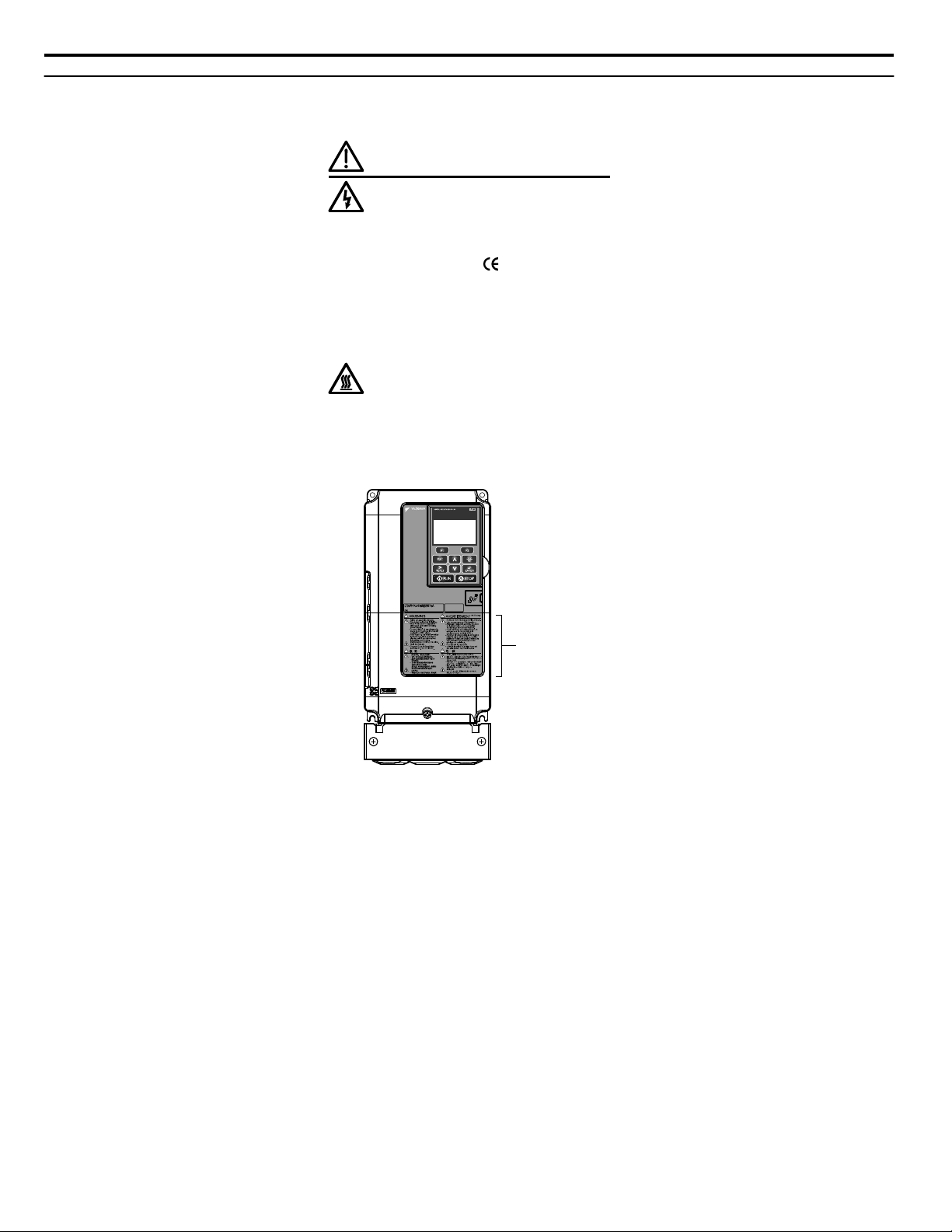
Warning Label
600V 3Phase 5.5kW/3.7kW
i.2 General Safety
u
Drive Label Warning Example
Always heed the warning information listed in Figure i.2 in the position shown in Figure i.3.
WARNING
Risk of electric shock.
●
Read manual before installing.
●
Wait 5 minutes for capacitor
discharge after disconnecting
power supply.
●
To conform to requirements,
make sure to ground the supply
neutral for 400V class.
●
After opening the manual switch
between the drive and motor,
please wait 5 minutes before
inspecting, performing
maintenance or wiring the drive.
Hot surfaces
●
Top and Side surfaces may
become hot. Do not touch.
Figure i.2 Warning Information Example
22
Figure i.3 Warning Information Position
YASKAWA SIEP YAIP1B 01A YASKAWA AC Drive – P1000 Bypass Technical Manual
Page 23
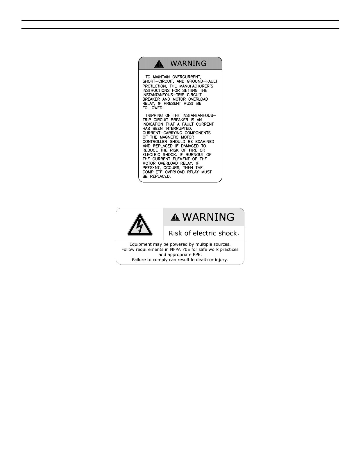
i.2 General Safety
u
Bypass Label Warning Example
Always heed the warning information listed in Figure i.4 and Figure i.5 affixed to the bypass cabinet door.
Figure i.4 Warning Information Example A
Figure i.5 Warning Information Example B
YASKAWA SIEP YAIP1B 01A YASKAWA AC Drive – P1000 Bypass Technical Manual
23
Page 24

i.2 General Safety
u
Warranty Information
Scope of Warranty
n
Inspections
Customers are responsible for periodic inspections of the drive. Upon request, a Yaskawa representative will inspect the drive
for a fee. If the Yaskawa representative finds the drive to be defective due to Yaskawa workmanship or materials and the
defect occurs during the warranty period, this inspection fee will be waived and the problem remedied free of charge.
Repairs
If a Yaskawa product is found to be defective due to Yaskawa workmanship or materials and the defect occurs during the
warranty period, Yaskawa will provide a replacement, repair the defective product, and provide shipping to and from the site
free of charge.
However, if the Yaskawa Authorized Service Center determines that the problem with the drive is not due to defective
workmanship or materials, the customer will be responsible for the cost of any necessary repairs. Some problems that are
outside the scope of this warranty are:
Problems due to improper maintenance or handling, carelessness, or other reasons where the customer is determined to be
responsible.
Problems due to additions or modifications made to a Yaskawa product without Yaskawa’s understanding.
Problems due to the use of a Yaskawa product under conditions that do not meet the recommended specifications.
Problems caused by natural disaster or fire.
After the free warranty period elapses.
Replenishment or replacement of consumables or expendables.
Defective products due to packaging or fumigation.
Other problems not due to defects in Yaskawa workmanship or materials.
Warranty service is only applicable within the country where the product was purchased. However, after-sales service is
available for customers outside of the country where the product was purchased for a reasonable fee.
Contact your local Yaskawa representative for more information.
Exceptions
Any inconvenience to the customer or damage to non-Yaskawa products due to Yaskawa’s defective products whether within
or outside of the warranty period are NOT covered by warranty.
Restrictions
n
The drive is not designed or manufactured for use in devices or systems that may directly affect or threaten human lives or
health.
Customers who intend to use the product described in this manual for devices or systems relating to transportation, health
care, space aviation, atomic power, electric power, or in underwater applications must first contact their Yaskawa
representatives or the nearest Yaskawa sales office.
WARNING! Injury to Personnel. This product has been manufactured under strict quality-control guidelines. However, if this product is to
be installed in any location where failure of this product could involve or result in a life-and-death situation or loss of human life or in a facility
where failure may cause a serious accident or physical injury, safety devices must be installed to minimize the likelihood of any accident.
24
YASKAWA SIEP YAIP1B 01A YASKAWA AC Drive – P1000 Bypass Technical Manual
Page 25

1
Receiving
This chapter explains how to inspect the P1000 Bypass upon receipt, and gives an overview of the
different enclosure types and components.
1.1 SECTION SAFETY.................................................................................................26
1.2 GENERAL DESCRIPTION.....................................................................................27
1.3 MODEL NUMBERS AND NAMEPLATE CHECKS................................................28
1.4 BYPASS COMPONENT DESCRIPTIONS.............................................................32
YASKAWA SIEP YAIP1B 01A YASKAWA AC Drive – P1000 Bypass Technical Manual
25
Page 26

1.1 Section Safety
1.1 Section Safety
NOTICE
Observe proper electrostatic discharge procedures (ESD) when handling the drive and circuit boards.
Failure to comply may result in ESD damage to the drive circuitry.
A motor connected to a PWM drive may operate at a higher temperature than a utility-fed motor and the operating
speed range may reduce motor cooling capacity.
Ensure that the motor is suitable for drive duty and/or the motor service factor is adequate to accommodate the additional
heating with the intended operating conditions.
26
YASKAWA SIEP YAIP1B 01A YASKAWA AC Drive – P1000 Bypass Technical Manual
Page 27

1.2 General Description
u
Control Mode Details
Table 1.1 gives an overview of the various features associated with the P1000 Bypass.
Table 1.1 Control Mode Features
Motor Type Induction Motors Comments
Control Mode V/f –
Basic Description V/f control –
Motor Type IM –
Type of Applications
Control Characteristics
Application-Specific
Multi Motor YES –
Motor data unknown YES –
High Speed Accuracy – –
Speed Control Range 1:40 May fluctuate with characteristics and motor temperature.
Speed Accuracy ±2 to 3%
Speed Response 3 Hz (approx.)
Starting Torque 140% at 3 Hz
Speed Search YES
Energy-Saving Control YES
High Slip Braking YES
Kinetic Energy Buffering YES
Overexcitation Deceleration YES Provides fast deceleration without using a braking resistor.
Overvoltage Suppression YES Prevents overvoltage by increasing speed during regeneration.
Speed deviation when operating at constant speed may fluctuate
with characteristics and motor temperature.
Max. frequency of a speed reference signal that the drive can follow
may fluctuate with characteristics and motor temperature.
Starting torque may fluctuate with characteristics and motor
temperature.
Performance may differ by capacity.
Bi-directional speed detection of a coasting motor to restart it
without stopping.
Saves energy by always operating the motor at its maximum
efficiency.
Increases motor loss to allow for faster deceleration. Effectiveness
may vary based on motor characteristics.
Decelerates the drive to allow it to ride through a momentary power
loss and continue operation.
1.2 General Description
Receiving
1
YASKAWA SIEP YAIP1B 01A YASKAWA AC Drive – P1000 Bypass Technical Manual
27
Page 28
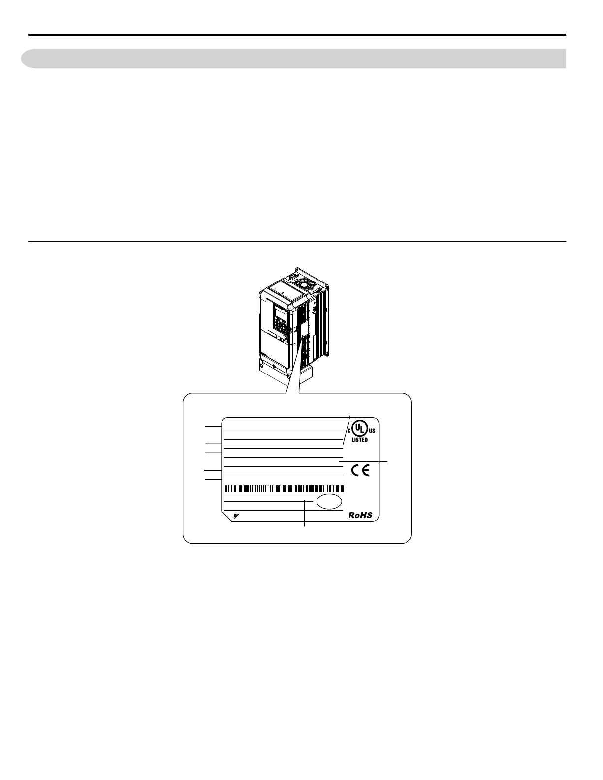
H
G
F
E
D
B
C
A
PRG : 8500
IND.CONT.EQ.
7J48 B
YASKAWA ELECTRIC CORPORATION
Assembled in USA
:
CIMR-PU2A0004FAA
PASS
MODEL
INPUT
OUTPUT
MASS
O / N
S / N
FILE NO
REV : A
: AC3PH 200-240V 50/60Hz 3. 9A
: AC3PH 0-240V 0-400Hz 3. 5A
: 3. 3 kg
:
:
: E131457 IP20
C/C
CIMR-PU2A0004FAA:
6W3050-0-100 VAJ123456
J0073D207410100
1.3 Model Numbers and Nameplate Checks
1.3 Model Numbers and Nameplate Checks
Please perform the following tasks after receiving the P1000 Bypass
• Inspect the P1000 Bypass for damage.
If the P1000 Bypass appears damaged upon receipt, contact the shipper immediately.
• Verify receipt of the correct model by checking the information on the nameplate.
• If you have received the wrong model or the P1000 Bypass does not function properly, contact your supplier.
If you find any irregularities in the above items, contact the shipping company, the distributor or representative you purchased
the P1000 Bypass from or your Yaskawa office immediately. The P1000 Bypass is thoroughly tested at the factory. Any
damages or shortages evident when the equipment is received must be reported immediately to the commercial carrier that
transported the material. Shipping damage is not covered by the Yaskawa warranty. After unpacking and inspecting for damage,
verify that internal wire connections have not come loose during shipment by spot checking wire terminations with a
screwdriver or the appropriate tool. P1000 Bypass storage must be in a clean and dry location. Maintain the factory packaging
and provide covering as needed to protect the P1000 Bypass from construction site dirt, water, debris and traffic prior to and
during construction.
u
Drive Nameplate
A – Normal Duty Amps
B – Software version
C – Enclosure type
D – Serial number
E – Lot number
F – Output specifications
G – Input specifications
H – AC drive model
Figure 1.1 Drive Nameplate Information Example
28
YASKAWA SIEP YAIP1B 01A YASKAWA AC Drive – P1000 Bypass Technical Manual
Page 29
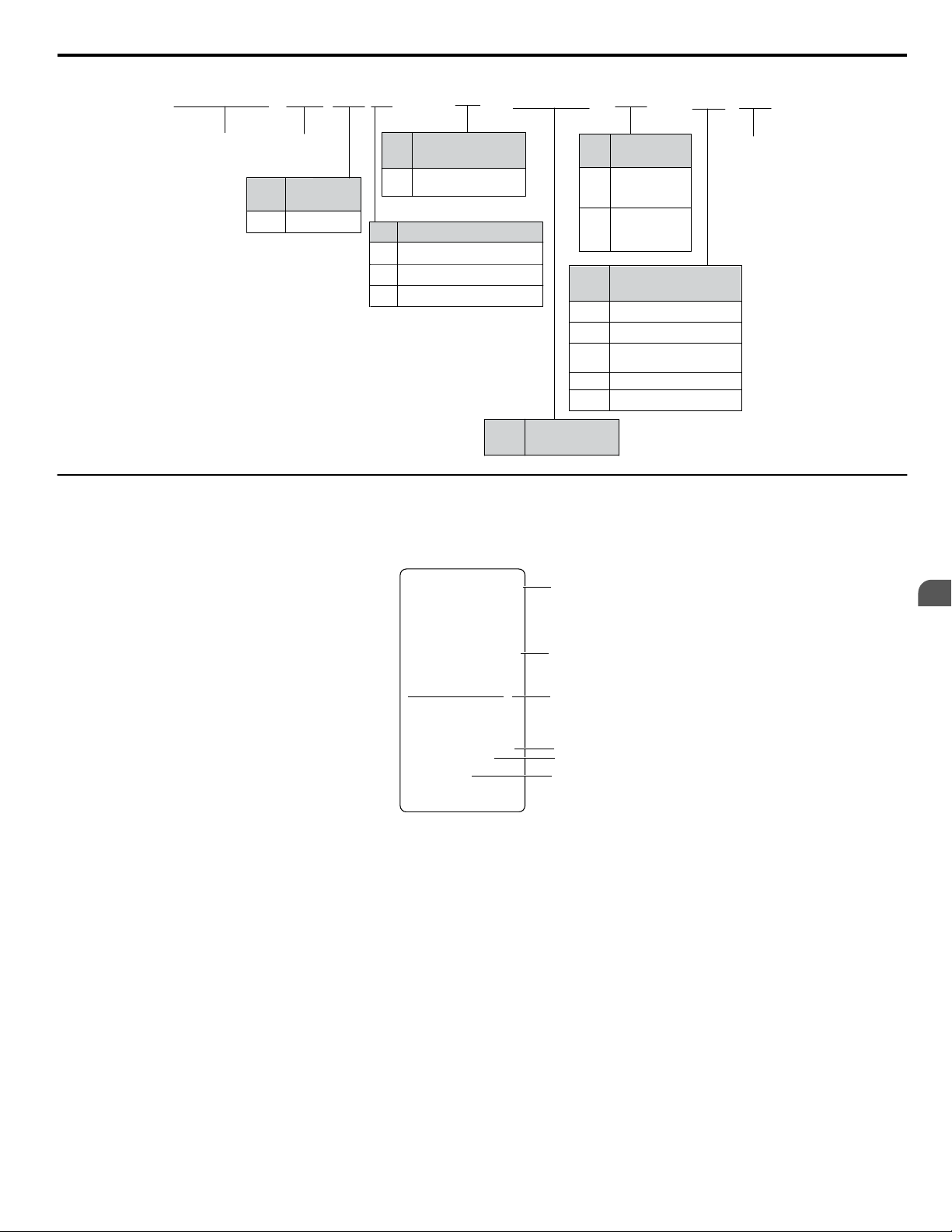
CIMR
-
P U 2 A
0021 F
A A
Drive
P1000
Series
No.
Enclosure
Type
Design
Revision
Order
No.
Customized
Specifications
A Standard model
IP00/Open
Type
F
IP20/NEMA
Type 1
A
No.
Environmental
Specification
K Gas-resistant
A
M
N
S
Standard
Humidity- and
dust-resistant
Oil-resistant
Vibration-resistant
No.
Region
Code
USA
U
No. Voltage Class
3-phase, 380-480 Vac
3-phase, 200-240 Vac
2
4
3-phase, 500-600 Vac 5
No.
Drive Model
Amp Rating
u
A
A.C. INPUT
A.C. OUTPUT
Designator Rating
Serial No.:4W11X2888880001
Model No. :P1B1D002PM
Type: P1000 BYPASS
W.D.: DS.P1B1.01
Inst. Manual:SIEPYAIP1B01,
TOECC71061615
F1,F2 FNQ-R1.5A,600V
Type
Volts: 208
Volts: 0-208
Hz: 50/60
Hz: 0-60
Phase: 3
Phase: 3
SCCR: 100kA rms sym.,208V max.
Amps: 2.9
Amps: 2.4
B
F
C
D
E
Bypass Nameplate
1.3 Model Numbers and Nameplate Checks
The nameplate is located on the inside of the P1000 Bypass enclosure door.
The nameplate shown below is an example for a standard P1000 Bypass.
YASKAWA SIEP YAIP1B 01A YASKAWA AC Drive – P1000 Bypass Technical Manual
A – Input specifications
B – Output specifications
C – Replacement fuse specifications
Figure 1.2 Bypass Nameplate Information Example
D – Serial number
E – Bypass model number
F – Schematic document number
(document included in packaging)
Receiving
1
29
Page 30
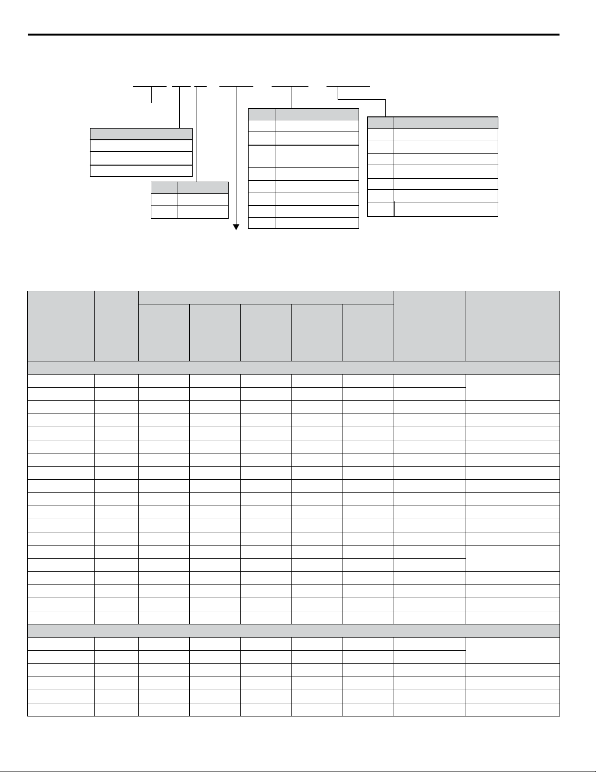
P1B 1 B
P1000
Bypass
No. Voltage
Refer to the following table
D 208 Vac
B 480 Vac
040 P T
A/K/R/X/Y
D/G/H/L/Q
W
M
No. Power Options
M
100 kA Input
Circuit Breaker
K Output Reactor 5%
A Two Motor “AND”
R Input Reactor 3%
N RFI Cap Filter
Y Two Motor “OR”
X DC Bus Reactor 3%
No. Control Options
H Profibus
G DeviceNet
D EtherNet/IP
M Keypad Viewing Window
L LonWorks
Q EtherNet MODBUS TCP/IP
No. Enclosure Type
3 NEMA Type 3R
2 NEMA Type 12
1 NEMA Type 1
3 50 ˚C Ambient
W Custom Nameplate
<1>
<1>
M
N
3
1.3 Model Numbers and Nameplate Checks
<1> Available for NEMA 3R enclosures only.
Bypass Models, Drive Models, and Capacities
n
P1B1
Bypass Model HP
D002 0.5 2.7 2.7 2.7 2.7 4.6 2.4
D003 0.75 3.9 3.9 3.9 4.6 5.8 3.5
D004 1 5.6 5.6 5.6 6.3 7.5 4.6 2A0006
D007 2 8.3 8.3 8.3 9.0 10.2 7.5 2A0008
D010 3 12.3 12.3 12.3 13.0 14.2 10.6 2A0012
D016 5 17.7 17.7 17.7 18.4 19.6 16.7 2A0018
D024 7.5 29.8 30.6 29.8 30.6 31.5 24.2 2A0030
D030 10 40.0 40.8 40.0 40.8 41.7 30.8 2A0040
D046 15 56.1 56.8 56.8 56.8 57.8 46.2 2A0056
D059 20 68.9 69.6 69.6 69.6 70.6 59.4 2A0069
D074 25 89.4 90.1 90.1 90.1 90.3 74.8 2A0081
D088 30 89.5 89.5 89.5 89.5 92.4 88.0 2A0110
D114 40 113.1 113.1 113.1 113.1 116.0 114.0 2A0138
D143 50 140.2 140.2 140.2 140.2 142.4 143.0
D169 60 165.4 165.4 165.4 165.4 167.6 169.0
D211 75 201.4 201.4 201.4 201.4 203.6 211.0 2A0211
D273 100 284.9 284.9 284.9 284.9 287.1 273.0 2A0312
D343 125 376.8 376.8 376.8 376.8 380.2 343.0 2A0360
D396 150 450.9 450.9 450.9 450.9 454.2 396.0 2A0415
B001 0.75 1.6 1.6 1.6 2.3 2.4 1.6
B002 1 2.1 2.1 2.1 2.8 2.9 2.1
B003 2 3.6 3.6 3.6 4.3 4.4 3.4 4A0004
B004 3 5.2 5.2 5.2 6.0 6.1 4.8 4A0005
B007 5 8.1 8.1 8.1 8.8 9.0 7.6 4A0009
B011 7.5 13.9 13.9 13.9 14.6 14.7 11.0 4A0011
30
Models
without
Power
Options
Models
PY Option
P1B1
with
Input (A)
P1B2 and
P1B3
Models
without
Power
P1B2
Models
with
PY Option
Options
208 Vac Bypass Drive
480 Vac Bypass Drive
YASKAWA SIEP YAIP1B 01A YASKAWA AC Drive – P1000 Bypass Technical Manual
P1B3
Models
with
P3 and PY
Options
Output (A) Drive Model
2A0004
2A0169
4A0002
Page 31

1.3 Model Numbers and Nameplate Checks
Input (A)
P1B1
Bypass Model HP
B014 10 16.0 16.7 16.0 16.7 16.7 14.0 4A0018
B021 15 21.9 22.6 21.9 22.6 22.6 21.0 4A0023
B027 20 33.1 33.8 33.8 33.8 33.8 27.0 4A0031
B034 25 39.4 40.1 40.1 40.1 40.1 34.0 4A0038
B040 30 47.3 48.0 48.0 48.0 48.0 40.0 4A0044
B052 40 52.7 52.7 52.7 52.7 54.0 52.0 4A0058
B065 50 65.5 65.5 64.8 64.8 66.5 65.0 4A0072
B077 60 76.7 76.7 76.0 76.7 77.6 77.0 4A0088
B096 75 99.3 99.3 98.6 99.3 100.2 96.0 4A0103
B124 100 128.1 128.1 127.4 128.1 129.1 124.0 4A0139
B156 125 162.2 162.2 162.2 162.2 163.1 156.0 4A0165
B180 150 180.6 180.6 180.6 180.6 181.5 180.0 4A0208
B240 200 239.5 239.5 239.5 239.5 241.0 240.0 4A0250
B302 250 290.1 290.1 290.1 290.1 291.6 302.0
B361 300 346.5 346.5 346.5 347.4 347.9 361.0
B414 350 411.4 411.4 412.4 413.6 412.9 414.0 4A0414
B477 400 433.1 433.1 433.1 434.3 435.2 477.0
B515 450 467.4 467.4 467.4 468.6 469.5 515.0
B590 500 576.7 576.7 576.7 577.9 578.8 590.0 4A0675
u
Bypass Enclosures
Models
without
Power
Options
P1B1
Models
with
PY Option
P1B2 and
P1B3
Models
without
Power
Options
P1B2
Models
with
PY Option
P1B3
Models
with
P3 and PY
Options
Output (A) Drive Model
4A0362
4A0515
Receiving
1
All P1000 Bypass units are intended for non-hazardous locations.
• P1000 Bypass units in NEMA Type 1 enclosures are constructed for indoor use to provide a degree of protection against
incidental contact with the enclosed electrical equipment and falling dust or dirt.
• P1000 Bypass units in NEMA Type 12 enclosures are constructed for indoor use to provide a degree of protection against
incidental contact with the enclosed electrical equipment, falling dust or dirt, circulating dust, dirt, lint, fibers and flyings,
and dripping at light splashing of liquids.
• P1000 Bypass units in NEMA Type 3 enclosures are constructed for indoor or outdoor use to provide a degree of protection
against incidental contact with the enclosed electrical equipment, falling dust or dirt, rain, sleet, snow, and wind-blown dust
or dirt. NEMA Type 3 enclosures will be undamaged by external formation of ice on the enclosure.
u
Bypass Product Options
Refer to Bypass Options on page 233 for details on available bypass product configuration options.
YASKAWA SIEP YAIP1B 01A YASKAWA AC Drive – P1000 Bypass Technical Manual
31
Page 32

Main disconnect handle
(shown in OFF position)
HOA keypad
F2F1
ESC
M M
AUTO OFF
ENTERRESET
ALM
DIGITAL OPERATOR JVOP-183
HAND
Alpha-numeric
LCD display
1.4 Bypass Component Descriptions
1.4 Bypass Component Descriptions
u
Bypass Front Control Panel
The external appearance and component names of the P1000 Bypass are shown in Figure 1.3.
Figure 1.3 P1000 Bypass Control Panel with Keypad Operator Controls
Refer to Using the HOA Keypad on page 59 for details on the HOA keypad.
Input Circuit Breaker
n
Electrically located on the input power side of the bypass, the input circuit breaker and its main disconnect handle provide a
means of disconnecting the bypass from line power for equipment maintenance. The handle must be in the OFF position to
open the bypass enclosure door. The handle can be locked in the OFF position using a padlock.
Contactors
n
The P1000 Bypass is a 3-contactor bypass circuit employing IEC rated contactors in an electrically interlocked arrangement
to allow mutually exclusive operation in Drive or Bypass modes.
The control logic and “soft start” characteristic of the drive limit the drive input and output contactors to motor FLA current
or less. The bypass contactor is exposed to motor inrush current (LRA) when starting the motor across-the-line and therefore
may require a higher current rating than the drive input and output contactors.
Overload Relay
n
The adjustable thermal overload relay (OLR) provides overload protection for the motor in Drive and Bypass operating modes.
The bypass three-phase output power connection to the motor is made to the output terminals of the OLR. The OLR is set up
in the factory to be a manual reset device, requiring operator attention if an overload trip-out is experienced.
Control Power Transformer
n
A Control Power Transformer (CPT) is provided to power the P1000 Bypass 120 Vac control circuit. The VA capacity is
determined by the control circuit and optional functions specified for the unit. The CPT primary is fused in both legs, the
secondary is fused when required by NEC (transformer VA and wire size dependent). One side of the transformer secondary
is grounded to the bypass enclosure.
Electronic Bypass Control Logic
n
Operating elements such as indicating LEDs, selector buttons, and control logic are incorporated into a PCB assembly to
eliminate the potential for loose wires after shipment.
The operating elements are located on PCB A3 and the control logic PCB A2 is mounted to the left-hand side of the enclosure
and contains the control circuit field wiring terminal blocks TB1 through TB3.
32
YASKAWA SIEP YAIP1B 01A YASKAWA AC Drive – P1000 Bypass Technical Manual
Page 33

E(G)
IG R+ R- S+ S-
S1 S2 S3 S4 S5 S6 S7 S8 SN SC SP
V+ AC A1 A2 A3 FM AM AC 24VRP AC
M1 M2 M3 M4
MD ME MF
MA MB MC
H
D
E
F
G
K
J
I
I
K
J
A
H
C
D
E
F
G
2A0012F 2A0110A
B
B
A
E(G)
IG R+ R- S+ S-
S1 S2 S3 S4 S5 S6 S7 S8 SN SC SP
V+ AC A1 A2 A3 FM AM AC 24VRP AC
M1 M2 M3 M4
MD ME MF
MA MB MC
1.4 Bypass Component Descriptions
Drive/Bypass Logic Interlocks
n
The P1000 Bypass 120 Vac logic circuit is interconnected with the drive multi-function digital input terminals and multifunction digital output terminals to allow a single customer interface to control both drive and bypass circuits. These drive
terminals are not available for field connections. All field control connections are connected to terminal blocks TB1 through
TB3 on control logic PCB A2 and drive control PCB A1.
u
Front Views
Receiving
1
A – Jumper S5 (Refer to Terminal FM/
AM Signal Selection on page 52)
B – Jumper S1 (Refer to Terminals A1,
A2, and A3 Input Signal Selection
on page 52)
C – Protective cover to prevent
miswiring
D – Main circuit terminal (Refer to
Wiring the Main Input Circuit on
page 45)
E – Terminal board (Refer to Control
Circuit Wiring on page 46)
F – Ground terminal
Figure 1.4 Front Views of P1000 Drives
G – DIP switch S2
H – Terminal board connector
I – Option card connector (CN5-C)
J – Option card connector (CN5-B)
K – Option card connector (CN5-A)
YASKAWA SIEP YAIP1B 01A YASKAWA AC Drive – P1000 Bypass Technical Manual
33
Page 34

A
B
C
D
E
1.4 Bypass Component Descriptions
A – Option card connector CN5
B – Terminal TB1
C – Terminal TB2
Figure 1.5 Front View of Bypass Control Board
D – Terminal TB3
E – Communications port CN2
34
YASKAWA SIEP YAIP1B 01A YASKAWA AC Drive – P1000 Bypass Technical Manual
Page 35

2
Mechanical Installation
This chapter explains how to properly mount and install the P1000 Bypass.
2.1 SECTION SAFETY.................................................................................................36
2.2 MECHANICAL INSTALLATION.............................................................................38
YASKAWA SIEP YAIP1B 01A YASKAWA AC Drive – P1000 Bypass Technical Manual
35
Page 36

2.1 Section Safety
2.1 Section Safety
WARNING
Crush Hazard
Use a dedicated lifting device when moving or positioning the drive.
Failure to comply may result in serious injury or death from falling equipment.
Use screws to securely affix the drive front cover, terminal blocks, and other drive components prior to vertical
suspension.
Failure to comply may result in serious injury or death from falling equipment.
Do not subject the bypass to vibration or impact greater than 1.96 m/s2 (0.2 G) while it is suspended by the cables.
Failure to comply may result in serious injury or death from falling equipment.
Do not attempt to flip the bypas over or leave the drive unattended while it is suspended by the wires.
Failure to comply may result in serious injury or death from falling equipment.
CAUTION
Crush Hazard
Do not carry the bypass by the front cover or the terminal cover.
Failure to comply may result in minor or moderate injury from the main body of the drive falling.
NOTICE
Equipment Hazard
Prevent foreign matter such as metal shavings or wire clippings from falling into the drive or bypass during drive
installation and project construction.
Failure to comply could result in damage to the drive and bypass. Place a temporary cover over the top during installation.
Be sure to remove the temporary cover before start-up, as the cover will reduce ventilation and cause the unit to overheat.
Observe proper electrostatic discharge (ESD) procedures when handling the bypass and drive.
Failure to comply could result in ESD damage to the drive and bypass circuitry.
Operating the motor in the low-speed range diminishes the cooling effects, increases motor temperature, and may
lead to motor damage by overheating.
Reduce the motor torque in the low-speed range whenever using a standard blower cooled motor. If 100% torque is required
continuously at low speed, consider using a special drive or vector-control motor. Select a motor that is compatible with the
required load torque and operating speed range.
The speed range for continuous operation differs according to the lubrication method and motor manufacturer.
If the motor is to be operated at a speed higher than the rated speed, consult with the manufacturer.
Continuously operating an oil-lubricated motor in the low-speed range may result in burning.
36
YASKAWA SIEP YAIP1B 01A YASKAWA AC Drive – P1000 Bypass Technical Manual
Page 37

2.1 Section Safety
NOTICE
When the input voltage is 480 V or higher or the wiring distance is greater than 100 meters, pay special attention to
the motor insulation voltage or use a drive-rated motor with reinforced insulation.
Failure to comply could lead to motor winding failure.
Motor vibration may increase when operating a machine in variable-speed mode, if that machine previously operated
at a constant speed.
Install vibration-proof rubber on the motor base or use the frequency jump function to skip a frequency resonating the
machine.
The motor may require more acceleration torque with drive operation than with a commercial power supply.
Set a proper V/f pattern by checking the load torque characteristics of the machine to be used with the motor.
The rated input current of submersible motors is higher than the rated input current of standard motors.
Select an appropriate drive according to its rated output current. When the distance between the motor and drive is long, use
a cable thick enough to connect the motor to the drive to prevent motor torque reduction.
The current rating for a motor with variable pole pitches differs from a standard motor.
Check the maximum current of the motor before selecting the drive capacity. Only switch motor poles when the motor is
stopped. Switching between motor during run will trigger overcurrent protection circuitry or result in overvoltage from
regeneration, and the motor will simply coast to stop.
Never lift or move the bypass while the cover is open.
This can damage the bypass components.
Mechanical Installation
2
YASKAWA SIEP YAIP1B 01A YASKAWA AC Drive – P1000 Bypass Technical Manual
37
Page 38

2.2 Mechanical Installation
2.2 Mechanical Installation
This section outlines specifications, procedures, and the environment for proper mechanical installation of the drive.
u
Installation Environment
Install the P1000 Bypass in an environment matching the conditions below to prolong its optimum performance life.
Move the disconnect handle into the OFF position to open the enclosure door for all bypass units. The wall mount units have
two full-turn fasteners, CCW to open, that require a flat blade screwdriver to open the enclosure door.
Wall mount units require a minimum 6 inch clearance above and below and a 3 inch clearance to the left to achieve adequate
heatsink cooling.
Table 2.1 Installation Environment
Environment Conditions
Installation Area Indoors
Ambient Temperature
Humidity 95% RH or less and free of condensation
Storage Temperature -20 to +60 °C
Surrounding Area
Altitude 1000 m or lower, up to 3000 m with derating. Refer to Drive Derating Data on page 231 for details.
Vibration
Orientation Install the bypass vertically to maintain maximum cooling effects.
-10 °C to +40 °C
Drive reliability improves in environments without wide temperature fluctuations.
Install the bypass in an area free from:
• radioactive materials
• combustible materials (e.g., wood)
• harmful gases and liquids
• excessive vibration
• chlorides
10 to 20 Hz at 3.24 m/s2 (10.6 ft/s2)
20 to 55 Hz at 2.16 m/s2 (7.1 ft/s2)
NOTICE: Avoid placing peripheral devices, transformers, or other electronics near the P1000 Bypass as the noise created can lead to
erroneous operation. If such devices must be used in close proximity to the Bypass, take proper steps to shield the bypass from noise.
NOTICE: Prevent foreign matter such as metal shavings and wire clippings from falling into the P1000 Bypass during installation. Failure
to comply could result in damage to the bypass. Place a temporary cover over the top of the drive during installation. Remove the temporary
cover before bypass start-up, as the cover will reduce ventilation and cause the Bypass to overheat.
38
YASKAWA SIEP YAIP1B 01A YASKAWA AC Drive – P1000 Bypass Technical Manual
Page 39

3
Electrical Installation
This chapter explains the proper procedures for wiring the control circuit terminals, motor, and power
supply.
3.1 SECTION SAFETY.................................................................................................40
3.2 STANDARD CONNECTION DIAGRAM.................................................................42
3.3 MAIN CIRCUIT WIRING.........................................................................................43
3.4 CONTROL CIRCUIT WIRING................................................................................46
3.5 BYPASS AND DRIVE CONTROL I/O CONNECTIONS........................................52
3.6 EXTERNAL INTERLOCK.......................................................................................54
YASKAWA SIEP YAIP1B 01A YASKAWA AC Drive – P1000 Bypass Technical Manual
39
Page 40

3.1 Section Safety
3.1 Section Safety
WARNING
Electrical Shock Hazard
Do not connect or disconnect wiring while the power is on.
Failure to comply may result in death or serious injury.
Before servicing, disconnect all power to the equipment. The internal capacitor remains charged even after the power supply
is turned off. The charge indicator LED will extinguish when the DC bus voltage is below 50 Vdc. To prevent electric shock,
wait for at least the time specified on the warning label, once all indicators are OFF, measure for unsafe voltages to confirm
the drive is safe prior to servicing.
Do not operate equipment with covers removed.
Failure to comply could result in death or serious injury.
The diagrams in this section may show drives without covers or safety shields to show details. Be sure to reinstall covers or
shields before operating the drives and run the drives according to the instructions described in this manual.
Make sure the protective earthing conductor complies with technical standards and local safety regulations.
Because the leakage current exceeds 3.5 mA, IEC/EN 61800-5-1 states that either the power supply must be automatically
disconnected in case of discontinuity of the protective earthing conductor or a protective earthing conductor with a crosssection of at least 10 mm2 (Cu) or 16 mm2 (Al) must be used. Failure to comply may result in death or serious injury.
Always use appropriate equipment for Ground Fault Circuit Interrupters (GFCIs).
The drive can cause a residual current with a DC component in the protective earthing conductor. Where a residual current
operated protective or monitoring device is used for protection in case of direct or indirect contact, always use a type B GFCI
according to IEC/EN 60755.
Always ground the motor-side grounding terminal.
Improper equipment grounding could result in death or serious injury by contacting the motor case.
Do not perform work on the drive while wearing loose clothing, jewelry or without eye protection.
Failure to comply could result in death or serious injury.
Remove all metal objects such as watches and rings, secure loose clothing, and wear eye protection before beginning work
on the drive.
Do not remove covers or touch circuit boards while the power is on.
Failure to comply could result in death or serious injury.
Do not allow unqualified personnel to perform work on the drive.
Failure to comply could result in death or serious injury.
Installation, maintenance, inspection, and servicing must be performed only by authorized personnel familiar with
installation, adjustment, and maintenance of AC drives.
Do not touch any terminals before the capacitors have fully discharged.
Failure to comply could result in death or serious injury.
Before servicing, disconnect all power to the equipment. The internal capacitor remains charged even after the power supply
is turned off. The charge indicator LED will extinguish when the DC bus voltage is below 50 Vdc. To prevent electric shock,
wait for at least the time specified on the warning label, once all indicators are OFF, measure for unsafe voltages to confirm
the drive is safe prior to servicing.
Fire Hazard
Tighten all terminal screws to the specified tightening torque.
Loose electrical connections could result in death or serious injury by fire due to overheating of electrical connections.
Do not use improper combustible materials.
Failure to comply could result in death or serious injury by fire.
Do not install the drive to a combustible surface. Never place combustible materials on the drive.
40
YASKAWA SIEP YAIP1B 01A YASKAWA AC Drive – P1000 Bypass Technical Manual
Page 41

3.1 Section Safety
WARNING
Do not use an improper voltage source.
Failure to comply could result in death or serious injury by fire.
Verify that the rated voltage of the drive matches the voltage of the incoming power supply before applying power.
Properly handle the HOA keypad battery.
Improper use of the battery may cause fire by explosion and personal injury.
Correctly install the battery, paying attention to polarity (+/-).
Do not attempt to charge the battery or improperly disassemble the HOA keypad.
NOTICE
Observe proper electrostatic discharge procedures (ESD) when handling the drive and circuit boards.
Failure to comply may result in ESD damage to the drive circuitry.
Never connect or disconnect the motor from the drive while the drive is outputting voltage.
Improper equipment sequencing could result in damage to the drive.
Do not use unshielded cable for control wiring.
Failure to comply may cause electrical interference resulting in poor system performance. Use shielded, twisted-pair wires
and ground the shield to the ground terminal of the drive.
Do not allow unqualified personnel to use the product.
Failure to comply could result in damage to the drive.
Do not modify the or bypass circuitry.
Failure to comply could result in damage to the drive or bypass and will void warranty.
Yaskawa is not responsible for any modification of the product made by the user. This product must not be modified.
Check all the wiring to ensure that all connections are correct after installation.
Failure to comply could result in damage to the drive.
Do not heat or throw the battery into fire.
The battery remains in use even when power to the drive has been shut off. Be sure to also remove the battery in the HOA
keypad when the drive will be shut off for long periods of time.
A dead battery left inside the HOA keypad may leak and damage the keypad and drive. Be sure to replace the battery with
a new one immediately after the expected lifespan has passed or when the “bAT” error is displayed on the HOA keypad.
Be sure to observe the Perchlorate Best Management Practices (BMPs).
BMPs apply to primary lithium (manganese dioxide) coin batteries sold or distributed in California. Perchlorate Materialspecial handling may apply, please refer to: www.dtsc.ca.gov/hazardouswaste/perchlorate.
Electrical Installation
3
YASKAWA SIEP YAIP1B 01A YASKAWA AC Drive – P1000 Bypass Technical Manual
41
Page 42

3.2 Standard Connection Diagram
3.2 Standard Connection Diagram
Connect the bypass and peripheral devices as shown in the schematic diagram shipped with the bypass. It is possible to set
and run the bypass via the HOA keypad without connecting digital I/O wiring. This section does not discuss drive operation;
Refer to Start-Up Programming & Operation on page 57 for instructions on operating the drive.
WARNING! Fire Hazard. Branch Circuit protection is required to be installed according to applicable local codes and the requirements listed
on the P1000 Bypass nameplate. Failure to comply could result in fire and damage to the bypass and drive or injury to personnel. The P1000
Bypass is suitable for use on a circuit capable of delivering not more than 100,000 RMS symmetrical amperes, 208 Vac and 480 Vac with
the circuit breaker option (PM) or when protected by class J or class L fuses as specified on the P1000 Bypass nameplate.
NOTICE: When the input voltage is 440 V or higher or the wiring distance is greater than 100 meters, pay special attention to the motor
insulation voltage or use a drive duty motor. Failure to comply could lead to motor insulation breakdown.
NOTICE: Do not connect AC control circuit ground to drive enclosure. Improper drive grounding can cause control circuit malfunction.
Note: The minimum load for relay outputs DO-7, DO-8, DO-9, DO-10, M1-M2, M3-M4, M5-M6, and MA-MB-MC is 10 mA.
WARNING! Sudden Movement Hazard. Do not close the wiring for the control circuit unless the multifunction input terminal parameters are
properly set. Improper sequencing of run/stop circuitry could result in death or serious injury from moving equipment.
WARNING! Sudden Movement Hazard. Ensure start/stop circuits are wired properly and in the correct state before energizing the drive.
Failure to comply could result in death or serious injury from moving equipment. When programmed for 3-Wire control, a momentary closure
on terminal S1 may cause the drive to start.
WARNING! Sudden Movement Hazard. When using a 3-Wire sequence, set the drive to 3-Wire sequence prior to wiring the control terminals
and set parameter b1-17 to 0 so the drive will not accept a Run command at power up (default). If the drive is wired for a 3-Wire sequence
but set up for a 2-Wire sequence (default), and parameter b1-17 is set to 1 so the drive accepts a Run command at power up, the motor
will rotate in reverse direction at drive power up and may cause injury.
WARNING! Sudden Movement Hazard. Confirm the drive I/O signals and external sequence before executing the application preset
function. Executing the application preset function or setting A1-06 ≠ 0 will change the drive I/O terminal functions and may cause unexpected
equipment operation. Failure to comply may cause death or serious injury.
NOTICE: Route motor leads U/T1, V/T2, and W/T3 separate from all other leads to reduce possible interference-related issues. Failure to
comply may result in abnormal operation of bypass and nearby equipment.
NOTICE: When using the automatic fault restart function with wiring designed to shut off the power supply upon drive fault, make sure the
drive does not trigger a fault output during fault restart (L5-02 = 0, default). Failure to comply will prevent the automatic fault restart function
from working properly.
42
YASKAWA SIEP YAIP1B 01A YASKAWA AC Drive – P1000 Bypass Technical Manual
Page 43

3.3 Main Circuit Wiring
3.3 Main Circuit Wiring
Note: Refer to the documentation packaged with the P1000 Bypass and labels placed in the Bypass enclosure for procedures required to safely
NOTICE: Do not solder the ends of wire connections to the bypass. Soldered wiring connections can loosen over time. Improper wiring
practices could result in malfunction due to loose terminal connections.
NOTICE: Do not switch the bypass input to start or stop the motor. Frequently switching the bypass on and off shortens the life of the DC
bus charge circuit and the DC bus capacitors, and can cause premature bypass failures. For the full performance life, refrain from switching
the bypass on and off more than once every 30 minutes.
u
Factory Recommended Branch Circuit Protection
WARNING! Fire Hazard. Branch Circuit protection is required to be installed according to applicable local codes and the requirements listed
on the P1000 Bypass nameplate. Failure to comply could result in fire and damage to the bypass and drive or injury to personnel. The P1000
Bypass is suitable for use on a circuit capable of delivering not more than 100,000 RMS symmetrical amperes, 208 Vac and 480 Vac with
the circuit breaker option or when protected by class J or class L fuses as specified on the P1000 Bypass nameplate.
Yaskawa recommends installing branch circuit protection according to maintain compliance with UL508C. Semiconductor
protective type fuses are preferred. Alternate branch circuit protection devices are also listed in this manual.
u
Drive Main Circuit Terminal Functions
and properly wire the Bypass main circuit.
Table 3.1 Main Circuit Terminal Functions
Terminal Description Function Page
R/L1
Main circuit power supply input Connects line power to the bypass 42S/L2
T/L3
U/T1
Drive output Connects to the motor 42V/T2
W/T3
For 200 V Class: 100 Ω or less
For 400 V Class: 10 Ω or less
Grounding terminal 44
Electrical Installation
u
Wire Gauge and Tightening Torque Specifications
Note: 1. For 0 to 100 A, use a minimum of 60 °C - 75 °C copper wire.
2. For above 100 A, use a minimum of 75 °C copper wire.
3. Wire gauge recommendations based on drive continuous current ratings using 75 °C 600 Vac vinyl-sheathed wire assuming ambient
temperature within 40 °C and wiring distance less than 100 m.
• Consider the amount of voltage drop when selecting wire gauges. Increase the wire gauge when the voltage drop is greater
than 2% of motor rated voltage. Ensure the wire gauge is suitable for the terminal block. Use the following formula to
calculate the amount of voltage drop:
Line drop voltage (V) = 3 × wire resistance (Ω/km) × wire length (m) × current (A) × 10
-3
•
• Refer to UL Standards Compliance on page 337 for information on UL compliance.
u
Main Input Circuit and Motor Wiring
This section outlines the various steps, precautions, and checkpoints for wiring the main circuit terminals and motor terminals.
WARNING! Electrical Shock Hazard. Do not connect the AC power line to the bypass output terminals. Failure to comply could result in
death or serious injury by fire as a result of bypass damage from line voltage application to output terminals.
NOTICE: When connecting the motor to the output terminals T1, T2, and T3, the phase order for the drive and motor should match. Failure
to comply with proper wiring practices may cause the motor to run in reverse if the phase order is backward.
NOTICE: Do not connect phase-advancing capacitors or LC/RC noise filters to the output circuits. Failure to comply could result in damage
to the drive, phase-advancing capacitors, LC/RC noise filters or ground fault circuit interrupters.
NOTICE: Route motor leads U/T1, V/T2, and W/T3 separate from all other leads to reduce possible interference-related issues. Failure to
comply may result in abnormal operation of bypass and nearby equipment.
3
YASKAWA SIEP YAIP1B 01A YASKAWA AC Drive – P1000 Bypass Technical Manual
43
Page 44

3.3 Main Circuit Wiring
Cable Length Between Bypass and Motor
n
Voltage drop along the motor cable may cause reduced motor torque when the wiring between the bypass and the motor is
too long, especially at low frequency output. This can also be a problem when motors are connected in parallel with a fairly
long motor cable. Bypass output current will increase as the leakage current from the cable increases. An increase in leakage
current may trigger an overcurrent situation and weaken the accuracy of the current detection.
Adjust the carrier frequency according to Table 3.2. If the motor wiring distance exceeds 100 m because of the system
configuration, reduce the ground currents. Refer to C6-02: Carrier Frequency Selection on page 104.
Table 3.2 Cable Length Between Bypass and Motor
Cable Length 50 m or less 100 m or less Greater than 100 m
Carrier Frequency 12.5 kHz or less 5 kHz or less 2 kHz or less
Note: 1. When setting carrier frequency for bypasses running multiple motors, calculate cable length as the total wiring distance to all connected
Ground Wiring
n
motors.
2. Do not use a long distance shielded line if there is an overvoltage problem at start. Either lower the carrier frequency or switch on the
internal EMC filter if the power supply has a neutral ground.
Follow the precautions below when wiring the ground for one bypass or a series of bypasses.
WARNING! Electrical Shock Hazard. Before servicing, disconnect all power to the equipment. The internal capacitor remains charged even
after the power supply is turned off. The charge indicator LED will extinguish when the DC bus voltage is below 50 Vdc. To prevent electric
shock, wait for at least the time specified on the warning label, once all indicators are OFF, measure for unsafe voltages to confirm the drive
is safe prior to servicing.
WARNING! Electrical Shock Hazard. Make sure the protective earthing conductor complies with technical standards and local safety
regulations. Because the leakage current exceeds 3.5 mA, IEC 61800-5-1 states that either the power supply must be automatically
disconnected in case of discontinuity of the protective earthing conductor or a protective earthing conductor with a cross-section of at least
10 mm2 (Cu) or 16 mm2 (Al) must be used. Failure to comply may result in death or serious injury.
WARNING! Electrical Shock Hazard. Always use a ground wire that complies with technical standards on electrical equipment and minimize
the length of the ground wire. Improper equipment grounding may cause dangerous electrical potentials on equipment chassis, which could
result in death or serious injury.
WARNING! Electrical Shock Hazard. Be sure to ground the drive ground terminal (208 Vac bypass drive: ground to 100 Ω or less and 480
Vac bypass drive: ground to 10 Ω or less). Improper equipment grounding could result in death or serious injury by contacting ungrounded
electrical equipment.
NOTICE: Do not share the ground wire with other devices such as welding machines or large-current electrical equipment. Improper
equipment grounding could result in drive or equipment malfunction due to electrical interference.
NOTICE: When using more than one drive, ground multiple drives according to instructions. Improper equipment grounding could result in
abnormal operation of drive or equipment.
Refer to Figure 3.1 when using multiple drives. Do not loop the ground wire.
The drive ground lug (terminal
) is connected to the enclosure. The enclosure ground lug must be connected to earth ground.
The drive has a second ground lug to accept the motor ground lead.
Figure 3.1 Ground Wiring for Multiple Bypass Units
44
YASKAWA SIEP YAIP1B 01A YASKAWA AC Drive – P1000 Bypass Technical Manual
Page 45

3.3 Main Circuit Wiring
u
Wiring the Main Input Circuit
WARNING! Electrical Shock Hazard. Shut off the power supply to the drive before wiring the main circuit terminals. Failure to comply may
result in death or serious injury.
Wire the main circuit terminals after the terminal board has been properly grounded.
Electrical Installation
3
YASKAWA SIEP YAIP1B 01A YASKAWA AC Drive – P1000 Bypass Technical Manual
45
Page 46

12. SHIELD
11. SHIELD
10. IG24
9. IG24
8. DI-8
7. DI-7
6. DI-6
5. DI-5
4. DI-4
3. DI-3
2. DI-2
1. DI-1
TB2
TB3
4. SHIELD
3. TXRX-
2. TXRX+
1. IG5
TB1
12. DO-10 NO
11. DO-10 C
10. DO-10 NC
9. DO-9 NO
8. DO-9 C
7. DO-9 NC
6. DO-8 NO
5. DO-8 C
4. DO-8 NC
3. DO-7 NO
2. DO-7 C
1. DO-7 NC
3.4 Control Circuit Wiring
3.4 Control Circuit Wiring
Note: Refer to the documentation packaged with the P1000 Bypass and labels placed in the bypass enclosure for procedures required to safely
u
Electronic Bypass Control Terminal Board A2
WARNING! Sudden Movement Hazard. Always check the operation and wiring of control circuits after being wired. Operating a P1000
Bypass with untested control circuits could result in death or serious injury.
WARNING! Sudden Movement Hazard. Confirm the drive I/O signals and external sequence before starting test run. Setting parameter
Z1-01 may change the I/O terminal function automatically from the default setting. Refer to Application Selection on page 75. Failure
to comply may result in death or serious injury.
The functions of the control circuit terminals are shown in Table 3.3.
The control circuit terminals are typically located on the interior left side of the bypass enclosure and are arranged as shown
in Figure 3.2.
and properly wire the bypass and drive control circuits.
Type Signal Name Description Specification
Digital Inputs
46
DI-1 Digital Input 1
DI-2 Digital Input 2
DI-3 Digital Input 3
DI-4 Digital Input 4
DI-5 Digital Input 5
DI-6 Digital Input 6
DI-7 Digital Input 7
DI-8 Digital Input 8
IG24 Isolated Ground Digital Input Common
Figure 3.2 Control Circuit Terminal Board A2 Arrangement
Table 3.3 P1000 Bypass Control Circuit Terminal Board A2
YASKAWA SIEP YAIP1B 01A YASKAWA AC Drive – P1000 Bypass Technical Manual
Dry contact rated, photocoupler sinking input to IG, 24 Vdc 8 mA,
ground fault protected
Page 47

E(G)
IG R+ R- S+ S-
S1 S2 S3 S4 S5 S6 S7 S8 SN SC SP
V+ AC A1 A2 A3 FM AM AC 24VRP AC
M1 M2 M3 M4
MD ME MF
MA MB MC
E(G)
IG R+ R- S+ S-
S1 S2 S3 S4 S5 S6 S7 S8 SN SC SP
V+ AC A1 A2 A3 FM AM AC 24VRP AC
M1 M2 M3 M4
MD ME MF
MA MB MC
3.4 Control Circuit Wiring
Type Signal Name Description Specification
DO-1 Digital Output 1
DO-2 Digital Output 2
Digital Outputs
120 Vac
DO-3 Digital Output 3
(Factory use only) 120 Vac, 66 VA sealed, 1650 inrush
DO-4 Digital Output 4
DO-5 Digital Output 5
DO-6 Digital Output 6
Digital Outputs
DO-7 Digital Output 7
DO-8 Digital Output 8
DO-9 Digital Output 9
Relay, dry contact, form C, 30 Vdc or 120 Vac,
DO-6 (factory use only), 3.7 Amp 360 VA,
DO-7 to DO-10 for customer use, 2 Amp
DO-10 Digital Output 10
Table 3.4 lists the available control circuit input terminals on the drive. Text in parenthesis indicates the default setting for
each multi-function input.
The drive control circuit terminals are arranged as shown in Figure 3.3.
Figure 3.3 Drive Control Circuit Terminal Board Arrangement
Table 3.4 Drive Control Circuit Terminal Board A1
Type No. Terminal Name (Function) Function (Signal Level) Default Setting Page
+V Power supply for analog inputs 10.5 Vdc (maximum allowable current 20 mA) 152
• 0 to 10 Vdc/100% (input impedance: 20 kΩ)
• 4 to 20 mA/100%, 0 to 20 mA/100% (input impedance: 250 Ω)
• Voltage or current input must be selected by Jumper S1 and H3-01.
• 0 to 10 Vdc/100% (input impedance: 20 kΩ)
• 4 to 20 mA/100%, 0 to 20 mA/100% (input impedance: 250 Ω)
• Voltage or current input must be selected by Jumper S1 and H3-09.
• -10 to 10 Vdc, 0 to 10 Vdc (input impedance: 20 kΩ)
• 4 to 20 mA, 0 to 20 mA (input impedance: 250 Ω)
• Voltage or current input must be selected by jumper S1 and H3-05.
117
152
119
152
152
152
Frequency
Reference
Inputs
Multi-function analog input 1
A1
(Frequency reference bias)
Multi-function analog input 2
A2
(Frequency reference bias)
Multi-function analog input 3
A3
(Auxiliary frequency reference 1)
AC Frequency reference common 0 V 152
FE Ground for shielded lines and option cards – –
u
Bypass Analog Outputs
There are two analog outputs that can be configured for a signal level of 0 to 10 Vdc or 4 to 20 mA. The signal level is controlled
by the position of jumpers J2 and J3 on Control PCB A2 and by the values set to drive parameters H4-07 and H4-08.
Electrical Installation
3
YASKAWA SIEP YAIP1B 01A YASKAWA AC Drive – P1000 Bypass Technical Manual
47
Page 48

3.4 Control Circuit Wiring
u
Serial Communications
Refer to BACnet Communications on page 287 or Refer to MEMOBUS/Modbus Communications on page 305 for details
depending on the applicable serial communications protocol.
Serial Communication Terminals
n
Table 3.5 Control Circuit Terminals: Serial Communications
Type Name Description Notes
Ground reference for RS-485 signals. This is an isolated ground
IG5 Isolated ground
MEMOBUS/Modbus or
BACnet
Communication
Bypass and Drive Control Circuit Wire Size and Torque Specifications
n
TXRX+ (+) Differential communication signal
TXRX- (-) Differential communication signal
SHIELD Shield tie point Connected to chassis ground
used only for communications and may be used in certain
circumstances to connect to other communication devices floating
ground references.
RS-485 signal levels
Select appropriate wire type and gauges from Table 3.6. For simpler and more reliable wiring, use crimp ferrules on the wire
ends. Refer to Table 3.7 for ferrule terminal types and sizes.
Table 3.6 Wire Gauge and Torque Values: Bypass and Drive Control Circuit
Bare Wire Terminal Ferrule-Type Terminal
Applicable
wire size
mm2 (AWG)
Stranded wire:
0.2 to 1.0
(24 to 16)
Solid wire:
0.2 to 1.5
(24 to 16)
Stranded wire:
0.2 to 1.0
(24 to 16)
Solid wire:
0.2 to 1.5
(24 to 16)
Recomm.
wire size
mm2 (AWG)
0.75 (18)
0.75 (18)
Applicable
wire size
mm2 (AWG)
0.25 to 0.5
(24 to 20)
0.25 to 0.5
(24 to 20)
Recomm.
wire size
mm2 (AWG)
0.5 (20)
0.5 (20)
Wire Type
Shielded wire,
etc.
Shielded wire,
etc.
Terminal
DO-7, DO-8, DO-9,
DO-10
DI-1, DI-2, DI-3, DI-4,
DI-5, DI-6, DI-7, DI-8,
IG24
IG5, TXRX+, TXRX-,
SHIELD
+V, A1, A2, A3, AC
FM, AM, AC
R+, R-, S+, S-, IG
Screw
Size
M3
M3
Tightening
Torque
N•m
(lb. in)
0.5 to 0.6
(4.4 to 5.3)
0.5 to 0.6
(4.4 to 5.3)
Ferrule-Type Wire Terminals
n
Yaskawa recommends using CRIMPFOX 6, a crimping tool manufactured by PHOENIX CONTACT, to prepare wire ends
with insulated sleeves before connecting to the drive. See Table 3.7 for dimensions.
d1
8 mm
L
d2
Figure 3.4 Ferrule Dimensions
Table 3.7 Ferrule Terminal Types and Sizes
48
2
Size mm
(AWG)
0.25 (24) AI 0.25-8YE 12.5 0.8 1.8
0.34 (22) AI 0.34-8TQ 10.5 0.8 1.8
0.5 (20)
Type L (mm) d1 (mm) d2 (mm) Manufacturer
AI 0.5-8WH or
AI 0.5-8OG
14 1.1 2.5
YASKAWA SIEP YAIP1B 01A YASKAWA AC Drive – P1000 Bypass Technical Manual
PHOENIX CONTACT
Page 49

3.4 Control Circuit Wiring
u
Drive Cover Removal
Refer to Table 3.8 and reference the standard P1000 Technical Manual (SIEPYAIP1U01) for detailed procedures on removing
and attaching drive covers.
Table 3.8 P1000 Bypass Models by P1000 Drive Model
Bypass Model Drive Model
208 Vac Bypass Drive
D002
D003
D004 2A0006
D007 2A0008
D010 2A0012
D016 2A0018
D024 2A0030
D030 2A0040
D046 2A0056
D059 2A0069
D074 2A0081
D088 2A0110
D114 2A0138
D143
D169
D211 2A0211
D273 2A0312
D343 2A0360
D396 2A0415
480 Vac Bypass Drive
B001
B002
B003 4A0004
B004 4A0005
B007 4A0009
B011 4A0011
B014 4A0018
B021 4A0023
B027 4A0031
B034 4A0038
B040 4A0044
B052 4A0058
B065 4A0072
B077 4A0088
B096 4A0103
B124 4A0139
B156 4A0165
B180 4A0208
B240 4A0250
B302
B361
B414 4A0414
B477
B515
B590 4A0675
2A0004
2A0169
4A0002
4A0362
4A0515
Electrical Installation
3
YASKAWA SIEP YAIP1B 01A YASKAWA AC Drive – P1000 Bypass Technical Manual
49
Page 50

A
B
C
D
Preparing wire
terminal ends
0.4
2.5
3.4 Control Circuit Wiring
u
Wiring the Drive Control Circuit Terminal
This section describes the proper preparations for wiring the control terminals.
Note: Refer to the P1000 standard Technical Manual (SIEPYAIP1U01) for figures showing correct control circuit wire routing.
WARNING! Electrical Shock Hazard. Do not remove covers or touch the circuit boards while the power is on. Failure to comply could result
in death or serious injury.
NOTICE: Separate control circuit wiring from main circuit wiring (terminals R/L1, S/L2, T/L3, -M, +M, -, +1, +3, U/T1, V/T2, W/T3) and other
high-power lines. Improper wiring practices could result in drive malfunction due to electrical interference.
NOTICE: Route motor leads U/T1, V/T2, and W/T3 separate from all other leads to reduce possible interference-related issues. Failure to
comply may result in abnormal operation of bypass and nearby equipment.
NOTICE: Separate wiring for digital output terminals MA, MB, MC, and M1 to M6 from wiring to other control circuit lines. Improper wiring
practices could result in drive or equipment malfunction or nuisance trips.
NOTICE: Use a class 2 power supply when connecting to the control terminals. Improper application of peripheral devices could result in
drive performance degradation due to improper power supply. Refer to NEC Article 725 Class 1, Class 2, and Class 3 Remote-Control,
Signaling, and Power Limited Circuits for requirements concerning class 2 power supplies.
NOTICE: Insulate shields with tape or shrink tubing to prevent contact with other signal lines and equipment. Improper wiring practices could
result in drive or equipment malfunction due to short circuit.
NOTICE: Connect the shield of shielded cable to the appropriate ground terminal. Improper equipment grounding could result in drive or
equipment malfunction or nuisance trips.
Wire the control circuit only after terminals have been properly grounded and main circuit wiring is complete. Refer to
Terminal Wiring Guide on page 50 for details. Prepare the ends of the control circuit wiring as shown in Figure 3.6.
NOTICE: Do not tighten screws beyond the specified tightening torque. Failure to comply may result in erroneous operation, damage to the
terminal block, or cause a fire.
NOTICE: Use shielded twisted-pair cables as indicated to prevent operating faults. Improper wiring practices could result in drive or
equipment malfunction due to electrical interference.
Connect control wires as shown in Figure 3.5.
Yaskawa recommends Phoenix Contact screwdriver model SZF 0-0.4 x 2.5 or equivalent to wire the terminal block.
A – Loosen screw to insert wire.
B – Single wire or stranded wire
Figure 3.5 Terminal Wiring Guide
C – Avoid fraying wire strands when
stripping insulation from wire. Strip
length 5.5 mm.
D – Blade depth of 0.4 mm or less
Blade width of 2.5 mm or less
Use the cable tie holes and cable hooks when wiring control terminals.
Note: Take proper precautions when wiring the cables so that the front covers will easily fit back onto the drive. Make sure cables are not pinched
between the front covers and the drive when replacing the covers.
When setting the frequency by analog reference from an external potentiometer, use shielded twisted-pair wires, preparing
wire ends as shown in Figure 3.6. Connect the shield to the ground terminal of the drive.
YASKAWA SIEP YAIP1B 01A YASKAWA AC Drive – P1000 Bypass Technical Manual
50
Page 51

A
E
B
C
D
E(G)
IG R+ R- S+ S-
S1 S2 S3 S4 S5 S6 S7 S8 SN SC SP
V+ AC A1 A2 A3 FM AM AC 24VRP AC
M1 M2 M3 M4
MD ME MF
MA MB MC
Selection
V
AM
FM
I
Jumper S5
Terminal AM/FM Signal
DIP Switch S2
RS-422/485 Termination
Resistor
Off On
Jumper S1
A1/A2/A3 Volt/Curr.
Selection
V
I
A1 A2 A3
3.4 Control Circuit Wiring
A – Drive side
B – Connect shield to ground terminal
of drive.
D – Control device side
E – Shield sheath (insulate with tape)
F – Shield
C – Insulation
Figure 3.6 Preparing the Ends of Shielded Cables
NOTICE: The analog signal wiring between the drive and the operator station or peripheral equipment should not exceed 50 meters when
using an analog signal from a remote source to supply the frequency reference. Failure to comply could result in poor system performance.
u
Switches and Jumpers on the Terminal Board
The terminal board is equipped with several switches used to adapt the drive I/Os to the external control signals. Figure 3.7
shows the location of these switches. Refer to Bypass and Drive Control I/O Connections on page 52 for setting instructions.
Figure 3.7 Locations of Jumpers and Switches on the Terminal Board
Electrical Installation
3
YASKAWA SIEP YAIP1B 01A YASKAWA AC Drive – P1000 Bypass Technical Manual
51
Page 52

V
I
A1 A2 A3
Jumper S1
3.5 Bypass and Drive Control I/O Connections
3.5 Bypass and Drive Control I/O Connections
u
Terminals A1, A2, and A3 Input Signal Selection
Terminals A1, A2, and A3 can be used to input either a voltage or a current signal. Select the signal type using jumper S1 as
explained in Table 3.9. Set parameters H3-01, H3-05, and H3-09 accordingly as shown in Table 3.10. Refer to Switches and
Jumpers on the Terminal Board on page 51 for locating jumper S1.
Note: If terminals A1 and A2 are both set for frequency bias (H3-02 = 0 and H3-10 = 0), both input values will be combined to create the frequency
reference.
Figure 3.8 Terminal A2 Set to Current Input; A1 and A3 Set to Voltage Input
Table 3.9 Jumper S1 Settings
Setting Description
V (top position) Voltage input (-10 to +10 V or 0 to 10 V)
I (bottom position) Current input (4 to 20 mA or 0 to 20 mA)
Table 3.10 Voltage/Current Selection Parameter Details
No. Parameter Name Description
Setting
Range
Default
Setting
Selects the signal level for terminal A1.
0: 0 to 10 Vdc
H3-01 Terminal A1 signal level selection
1: 0 to 10 Vdc Bipolar
0 to 3 0
2: 4 to 20 mA
3: 0 to 20 mA
Selects the signal level for terminal A3.
0: 0 to 10 Vdc
H3-05 Terminal A3 signal level selection
1: 0 to 10 Vdc Bipolar
0 to 3 0
2: 4 to 20 mA
3: 0 to 20 mA
Selects the signal level for terminal A2.
0: 0 to 10 Vdc
H3-09 Terminal A2 signal level selection
1: 0 to 10 Vdc Bipolar
0 to 3 2
2: 4 to 20 mA
3: 0 to 20 mA
u
Terminal FM/AM Signal Selection
The signal type for terminals FM and AM can be set to either voltage or current output using jumper S5 on the terminal board
as explained in Table 3.11. When changing the setting of jumper S5, parameters H4-07 and H4-08 must be set accordingly.
The default selection is voltage output for both terminals. Refer to Switches and Jumpers on the Terminal Board on page
51 for locating jumper S5.
Table 3.11 Jumper S5 Settings
Terminal Voltage Output Current Output
52
Terminal FM
Terminal AM
V
I
AMFM
V
I
AMFM
V
I
AMFM
V
I
AMFM
YASKAWA SIEP YAIP1B 01A YASKAWA AC Drive – P1000 Bypass Technical Manual
Page 53

3.5 Bypass and Drive Control I/O Connections
Table 3.12 Parameter H4-07 and H4-08 Details
No. Parameter Name Description
H4-07 Terminal FM signal level selection
H4-08 Terminal AM signal level selection
0: 0 to 10 Vdc
2: 4 to 20 mA
Setting
Range
0, 2 0
Default
Setting
Electrical Installation
3
YASKAWA SIEP YAIP1B 01A YASKAWA AC Drive – P1000 Bypass Technical Manual
53
Page 54

3.6 External Interlock
3.6 External Interlock
Systems that may be affected during drive fault conditions should be interlocked with the drive fault output and ready signal.
u
Annunciation Contact Outputs
Annunciation contacts for customer use are provided at terminal blocks TB1 as indicated in Table 3.13. Annunciation contacts
are used to indicate the status of bypass operation. Contacts are rated for 2 Amps, 24 Vdc/120 Vac +/- 15% maximum.
Table 3.13 Annunciation Contact Details
Function
Motor Run DO-7 TB1 1-2-3 Form C
Hand Mode DO-8 TB1 4-5-6 Form C
Auto Mode DO-9 TB1 7-8-9 Form C
System Fault DO-10 TB1 10-11-12 Form C
<1> Default settings are shown. Set parameters Z2-23 to Z2-26 to choose other functions.
The function of output relays DO-7 through DO-10 may be reprogrammed via bypass parameters Z2-23 through Z2-26. These
form C dry contact relays are for customer use in annunciation to building automation systems (BAS) or other circuits. Each
contact is rated for 2 amps at 120 Vac.
Refer to Z2-01 to Z2-08: Digital Input 1 to 8 Function Select on page 161 for descriptions of the programmable functions
of annunciation contacts.
<1>
Name Terminal Block Terminals Type
u
Building Automation System Run/Stop Circuit
DI-1 (TB2-1 by default setting in Z2-01) is available to connect the normally open (N.O.) Run/Stop contact from a BAS or
other remote controller for auto mode control.
These terminals must have contact closure for the motor to run in AUTO mode.
u
Safety Interlock Circuit
DI-2 (TB2-2 by default setting in Z2-02) is provided to connect safety devices in a normally-closed series circuit, such as:
freeze up thermostats, smoke/fire sensors, high pressure limits, temperature limits or vibration detectors.
The HOA keypad will display the status “Safety Open”, and trigger a Safety Open fault if a N.C. safety circuit is not closed
between DI-2 and IG24 (TB2-10) on PCB A2 at power-up with a Run command in HAND or AUTO mode. An open circuit
between DI-2 and IG24 will prevent bypass operation.
Take one of the following steps to ensure proper operation prior to startup:
Install a N.C. safety circuit between DI-2 and IG24 on PCB A2.
1.
Install a jumper between DI-2 and IG24 (on PCB A2. A normally-closed safety circuit may also be used in place of
2.
this jumper.
u
Building Automation System Interlock Circuit (Drive and Bypass Enable Input)
The HOA keypad will display the status “INTRLOCK OPN” and possibly a “BAS Ilock-open” alarm or “BAS Ilock TO”
fault if a N.C. safety circuit is not closed between DI-3 (TB2-3 by default setting of Z2-03) and IG24 on PCB A2 at powerup with a Run command in HAND or AUTO mode. An open circuit between TB2-3 and IG24 (TB2-10) will prevent bypass
operation.
Take one of the following steps to ensure proper operation prior to startup:
Install a N.C. BAS Interlock Circuit/Damper Interlock between DI-3 and IG24 on PCB A2.
1.
Install a jumper between DI-3 and IG24 on PCB A2. A normally-closed BAS interlock may also be used in place of
2.
this jumper.
54
YASKAWA SIEP YAIP1B 01A YASKAWA AC Drive – P1000 Bypass Technical Manual
Page 55

3.6 External Interlock
u
Remote Transfer to Bypass
Terminal TB2-4 is a programmable input with a default setting of “Remote Transfer to Bypass” operation. The function of
this terminal can be changed using parameter Z2-04.
This function allows a contact closure from a BAS, between terminals TB2-4 and TB2-10, to transfer motor operation from
Drive mode to Bypass mode. An open contact allows operation in Drive mode and a closed contact allows operation in Bypass
mode.
u
Smoke Purge Operation
Terminal TB2-5 is a programmable input with a default setting of “Smoke Purge” operation. The function of this terminal can
be changed using parameter Z2-05.
This function allows a contact closure between terminals TB2-5 and TB2-10 to transfer motor operation to bypass for smoke
purge operation. The motor overload and Safety Interlock circuit are overridden during smoke purge or in emergency fire/
smoke situations to place priority on personnel protection.
Note: Smoke purge overrides all control inputs and bypass selector buttons. Smoke purge operation can only be terminated by opening the contact
u
Spare Multi-Function Digital Inputs
Terminals TB2-6 and TB2-7 are spare programmable inputs. The Bypass +24 V logic circuit is interconnected with the drive
multi-function digital inputs to allow a single customer interface to control both drive and bypass circuits. The function of
these terminals can be set using parameters Z2-06 and Z2-07.
closure at terminal TB2-5 or by opening the disconnect switch.
Electrical Installation
3
YASKAWA SIEP YAIP1B 01A YASKAWA AC Drive – P1000 Bypass Technical Manual
55
Page 56

3.6 External Interlock
This Page Intentionally Blank
56
YASKAWA SIEP YAIP1B 01A YASKAWA AC Drive – P1000 Bypass Technical Manual
Page 57

4
Start-Up Programming & Operation
This chapter explains HOA keypad functions and gives instructions on programming the P1000 Bypass
for initial operation.
4.1 SECTION SAFETY.................................................................................................58
4.2 USING THE HOA KEYPAD....................................................................................59
4.3 THE DRIVE AND PROGRAMMING MODES.........................................................66
4.4 POWERING UP THE DRIVE..................................................................................70
4.5 START-UP PROCEDURE......................................................................................71
4.6 APPLICATION SELECTION..................................................................................75
4.7 AUTO-TUNING.......................................................................................................76
YASKAWA SIEP YAIP1B 01A YASKAWA AC Drive – P1000 Bypass Technical Manual
57
Page 58

4.1 Section Safety
4.1 Section Safety
WARNING
Electrical Shock Hazard
Do not connect or disconnect wiring while the power is on.
Failure to comply could result in death or serious injury.
Before servicing, disconnect all power to the equipment. The internal capacitor remains charged even after the power supply
is turned off. The charge indicator LED will extinguish when the DC bus voltage is below 50 Vdc. To prevent electric shock,
wait for at least the time specified on the warning label, once all indicators are OFF, measure for unsafe voltages to confirm
the drive is safe prior to servicing.
Do not operate equipment with covers removed.
Failure to comply could result in death or serious injury.
The diagrams in this section may include drives without covers or safety shields to illustrate details. Be sure to reinstall
covers or shields before operating the drives and run the drives according to the instructions described in this manual.
Do not remove covers or touch circuit boards while the power is on.
Failure to comply could result in death or serious injury.
58
YASKAWA SIEP YAIP1B 01A YASKAWA AC Drive – P1000 Bypass Technical Manual
Page 59

F2F1
ESC
M M
AUTO OFF
ENTERRESET
ALM
DIGITAL OPERATOR JVOP-183
HAND
12
11
9
8
1
2
3
10
4 5 6 7
AUTO
OFF
HAND
AUTO
HAND
4.2 Using the HOA Keypad
4.2 Using the HOA Keypad
Use the HOA keypad to enter OFF commands, switch AUTO or HAND Mode, change parameters, and display data including
fault and alarm information.
u
HOA Keypad Keys and Displays
Figure 4.1 Description of HOA Keypad Keys and Displays
No. Display Name Function
1
F1
F2
Function Key F1
(Drive Test)
Function Key F2
(Bypass/Drive)
Selects Drive Test Mode
Toggles selection between Bypass Mode and Drive Mode.
• Returns to the previous display.
• Moves the cursor one space to the left.
2
ESC
ESC Key
• In Drive Mode, pressing and holding this button will return to the Frequency Reference display.
• In Bypass Mode, pressing and holding this button will return to the Bypass Main Menu.
• During parameter entry, allows aborting the current edited value and exits the parameter editing
mode.
3 RESET Key
4
AUTO Key Selects AUTO mode.
• Moves the cursor to the right.
• Resets the bypass or drive to clear a fault situation.
5 Up Arrow Key Scrolls up to display the next item, selects parameter numbers, and increments setting values.
6 Down Arrow Key Scrolls down to display the previous item, selects parameter numbers, and decrements setting values.
Selects OFF mode.
7
OFF Key
If the drive was operating the motor, the motor will stop according to the stopping method selected in
b1-03.
If the bypass was operating the motor, the bypass contactor opens and the motor coasts to a stop.
8 ENTER Key
9
HAND Key Selects HAND mode.
• Enters parameter values and settings.
• Selects a menu item to move between displays.
Start-Up Programming
& Operation
4
10
11
AUTO Light Lit while the drive is in AUTO mode. Refer to page 62 for details.
HAND Light Lit while the drive is in HAND mode. Refer to page 62 for details.
12 ALM LED Light Refer to ALARM (ALM) LED Displays on page 62.
YASKAWA SIEP YAIP1B 01A YASKAWA AC Drive – P1000 Bypass Technical Manual
59
Page 60

5
3
1 2
6
]
4
]
7
4.2 Using the HOA Keypad
u
LCD Display
Figure 4.2 LCD Display
Table 4.1 Display and Contents
No. Name Display Content
DRV
1 Bypass/Drive Status Display
(not
blinking)
DRV
(blinking)
BYP
(not
blinking)
BYP
(blinking)
Displayed when In Drive Mode. The bypass will run in Drive Mode when a Run command is present.
Displayed when in Drive Mode, but a condition is making the bypass run in Bypass Mode.
Displayed when in Bypass Mode. The Bypass will run in Bypass Mode when a Run command is
present.
Drive input contactor K1 is open and the drive will be powered down.
Displayed when in Bypass Mode with Drive Test Mode set. The bypass will run in Bypass Mode
when a Run command is present.
Drive input contactor K1 is closed and the drive is powered on.
60
YASKAWA SIEP YAIP1B 01A YASKAWA AC Drive – P1000 Bypass Technical Manual
Page 61

No. Name Display Content
POWERUP Displayed when the bypass is powering up.
OFF Displayed when no Run command is present and the safety circuit is closed.
2 Bypass Status Display
WAIT_FOR
_RUN
SAFETY
OPEN
INTRLOCK
OPN
PRE RUN
DRIVE
RUN
DRIVE
RUN
BYPASS
RMOT
XFER EN
SMOK PRG
BYP
SMOK PRG
DRV
AUTO
XFER EN
ENRGY
SAVEN
MTR
STOPPING
Displayed when Run is requested, the safety circuit is closed, and the bypass is waiting for Run input.
Displayed when the safety circuit input is open.
Displayed when a Run command is present, the safety circuit is closed, but the Interlock input is open.
Displayed when the bypass is running in the Pre-Run State at the programmed frequency for the
programmed time.
Displayed when running in Drive Mode.
Displayed when running in Bypass Mode.
Displayed when running in Remote Transfer.
Displayed when running in Smoke Purge Bypass.
Displayed when running in Smoke Purge Drive.
Displayed when running in Auto Transfer, a fault was detected and switched to Bypass Mode.
Displayed when running in Energy Savings Mode
Displayed when fault is removed but motor is still ramping down.
FAULTED Displayed when a fault has been detected causing motor output contactors to open.
3 Data Display — Displays specific data and operation data.
OPR Displayed when the frequency reference source is the HOA keypad.
Frequency
4
Reference
<1>
Source
COM
OP Displayed when the frequency reference source is an option card connected to the drive.
Displayed when the frequency reference source is the MEMOBUS/Modbus Communication Inputs
of the drive.
AI Displayed when the function reference is assigned to an analog input.
OFF Displayed when HAND mode is OFF.
RSEQ Displayed when the run command is supplied from a remote source.
5
LOCAL/REMOTE
Display
<2>
LSEQ Displayed when the run command is supplied from the operator keypad.
RREF Displayed when the run command is supplied from a remote source.
LREF Displayed when the run command is supplied from the operator keypad.
DATA
6
Function Key 2
(F2)
→
DRV/BYP
HELP
←
HOME
7
Function Key 1
(F1)
ESC
Monitor
RLY
Pressing
Pressing
Pressing
Pressing
Pressing
Pressing
Pressing
Pressing
Pressing
Mode (Open/Close K1).
F2
scrolls to the next display.
F2
scrolls the cursor to the right.
F2
toggles selection between Bypass Mode and Drive Mode.
F1
displays the Help menu.
F1
scrolls the cursor to the left.
F1
returns to the top menu (Frequency Reference).
F1
returns to the previous display.
F1
switches Monitor mode.
F1
selects/deselects Drive Test Mode. Enters and exits Drive Test Mode when in Bypass
<1> Displayed when in Frequency Reference Mode.
<2> Displayed when in Frequency Reference Mode and Monitor Mode.
4.2 Using the HOA Keypad
Start-Up Programming
& Operation
4
YASKAWA SIEP YAIP1B 01A YASKAWA AC Drive – P1000 Bypass Technical Manual
61
Page 62

AUTO
HAND
AUTO
HAND
AUTO
HAND
AUTO
HAND
AUTO
HAND
4.2 Using the HOA Keypad
u
Bypass Control Board LEDs
The bypass control board A2 has six bi-color LEDs.
The operational states of the bypass LEDs after completion of the power-up diagnostic LED sequence are described in Table
4.2. Wait at least 2 seconds for the power-up diagnostic process to complete before verifying LED states.
Table 4.2 Bypass Control Board LED States
Name Description Color Behavior
Red Not used
MS Module Status
NS Network Status
ST1 ST1, Status 1
ST2 ST2, Status 2
ST3 ST3, Status 3
ST4 ST4, Status 4
Green
Red Not used
Green
Red Not used
Green
Red Not used
Green
Red Not used
Green Not used
Red Not used
Green Not used
Turns ON when transmitting
Turns OFF when receiving
Turns ON when transmitting
Turns OFF when receiving
Round status
Toggles ON/OFF every 500 rounds
Scan status
Toggles ON/OFF every 500 scans
u
ALARM (ALM) LED Displays
Table 4.3 ALARM (ALM) LED Status and Contents
State Content Display
Illuminated When the drive detects an alarm or error.
• When an alarm occurs.
Flashing
• When an oPE is detected.
• When a fault or error occurs during Auto-Tuning.
Off Normal operation (no fault or alarm).
u
AUTO LED and HAND LED Indications
Table 4.4 AUTO LED and HAND LED Indications
AUTO LED HAND LED State
Off
Off
OFF mode
HAND mode
Off
On solid
HAND mode when the Frequency Reference is 0 and/or decelerating in HAND mode.
Off
Long blink (50% duty)
On solid
Long blink (50% duty)
62
Off
Off
Running in AUTO mode
Running in AUTO mode when the Frequency Reference is 0 and/or decelerating in AUTO
mode.
YASKAWA SIEP YAIP1B 01A YASKAWA AC Drive – P1000 Bypass Technical Manual
Page 63

AUTO LED HAND LED State
AUTO
HAND
AUTO
HAND
Long blink
(50% dut y)
Double blin k
Short lin k
(15% dut y)
1 s
2 s
ON ON ON
ON ON ON ON ON ON
ON ON
OFF ON Blink OFF Blink OFF
Output Frequency
RUN Command
Frequency
AUTO LED
HAND Mode Selection
AUTO Mode Selection
OFF AUTOOperation Mode
OFFHAND LED
OFF
0 Hz
6 Hz
ON
Short blink
4.2 Using the HOA Keypad
Short blink (15% duty)
Double blink
AUTO mode, Ready, No run command input.
AUTO mode, stopped by a Fast- Stop from a Multi-Function Digital Input.
1 s
ON
ON
ON ON
Flashing
Flashing
quickly
Off
Off
ON ON
Figure 4.3 AUTO LED and OFF LED Status and Meaning
Figure 4.4 LEDs and Drive Operation in AUTO Mode
Figure 4.5 LEDs and Drive Operation in HAND Mode
Start-Up Programming
& Operation
4
YASKAWA SIEP YAIP1B 01A YASKAWA AC Drive – P1000 Bypass Technical Manual
63
Page 64

<3>
<4>
Modified Consts
HELP
HELP
DATA
Quick Setting
DATA
HELP
DRV-OFF
Auto-Tuning
DATA
AUTO
Modified
X Parameters
YASKAWA
P1000
P1000 Bypass
Control
(VST00029 )
Initial Display <5>
<6>
Programming Mode <2> Drive or Bypass Mode <1>
DRV-OFF
U1-01= 0.00Hz
U1-02= 0.00Hz
U1-03= 0.00 A
Freq Ref (AUTO)
LSEQ
LREF
DRV-OFF
U1-01= 0.00Hz
U1-02= 0.00Hz
U1-03= 0.00 A
Monitor Menu
LSEQ
LREF
1
DRV-OFF
U2-01= oC
U1-02= oPr
U1-03= 0.00Hz
Fault Trace
LSEQ
LREF
1
DRV-OFF
U1-02= 0.00Hz
U1-03= 0.00A
U1-04= 0
Output Freq
LSEQ
LREF
1
DRV-OFF
U1-01= 60.00Hz
U1-02= 0.00Hz
U1-03= 0.00A
Frequency Ref
LSEQ
LREF
1
DRV-OFF
U1-01= 0.00Hz
U1-02= 0.00Hz
U1-03= 0.00 A
Monitor Menu
LSEQ
LREF
1
DRV-OFF
DRV-OFF
DRV-OFF
Programming
DATAHELP
RLY
DRV/BYP
RLY
DRV/BYP
RLY
DRV/BYP
RLY
DRV/BYP
RLY
DRV/BYP
RLY
DRV/BYP
AUTO
HAND
0
BYP-OFF
C1-01=
30.0sec
<Drive Off>
Accel Time 1
4.2 Using the HOA Keypad
u
HOA Keypad Menu Structure
Figure 4.6 HOA Keypad Menu and Screen Structure
<1>
Pressing
<2> In Programming Mode, the AUTO and HAND keys are ignored.
<3> Flashing characters are shown with white letters on gray background. (Example:
<4> “X” characters are used as examples in this manual. The HOA keypad will display the actual setting values.
or
will start the motor.
)
<5> The Frequency Reference appears after the initial display that shows the product name.
<6> The information that appears on the display will vary depending on the drive.
u
HOA Keypad Parameter Display (Drive Off)
The display of the drive-specific parameters changes when in bypass mode or when there is no power to the drive.
64
Figure 4.7 Drive-Specific Parameter
YASKAWA SIEP YAIP1B 01A YASKAWA AC Drive – P1000 Bypass Technical Manual
Page 65

BYP-OFF
C1-02=
<Drive Off>
Decel Time 1
BYP-OFF
C1-02= 10.0Hz
(0.0 ~ 60.0)
“10.0Hz”
Hand Fref
BYP-RUN BYPASS
U1 - 01=
U1 - 01=
U1 - 01=
Monitor
RLY
DRV/BYP
FWD
RSEQ
RREF
BYP-RUN BYPASS
UB-01= 10.6A
U1-02= 10000111
U1-03= 01001100
Bypass Monitors
RLY
DRV/BYP
FWD
RSEQ
RREF
4.2 Using the HOA Keypad
Figure 4.7 shows the LCD display with a typical drive-specific parameter displayed and no power to the drive. In this example,
the parameter displayed is stored both in the drive and in the bypass controller, so the present value is shown. The parameter
cannot be changed when there is no power present on the drive. All drive-specific parameter numbers will NOT begin with
the letter “Z”.
Figure 4.8 Drive-Specific Parameter
Figure 4.8 shows the LCD display with a typical drive-specific parameter displayed and no power to the drive. In this example,
the parameter displayed is only stored in the drive so the present value of the parameter is not displayed. This parameter cannot
be changed when there is no power present on the drive. All drive-specific parameter numbers will NOT begin with the letter
“Z”.
Figure 4.9 Bypass-Specific Parameter
Figure 4.9 shows the LCD display with a typical bypass-specific parameter displayed. This value can be changed regardless
if there is power present on the drive or not. All bypass-specific parameter numbers will begin with the letter “Z”.
Figure 4.10 Drive-Specific Monitors
Figure 4.10 shows the LCD display with drive-specific monitors displayed and no power to the drive. With no power to the
drive, the bypass controller cannot retrieve the information from the drive and the present values of the monitor is replaced
with dashes. Drive-specific monitor numbers begin with “U1”, “U2”, “U3”, “U4”, or “U5”.
Figure 4.11 Bypass-Specific Monitors
Figure 4.11 shows the LCD display with bypass-specific monitors displayed. Bypass-specific monitor numbers begin with
“UB”.
Start-Up Programming
& Operation
4
YASKAWA SIEP YAIP1B 01A YASKAWA AC Drive – P1000 Bypass Technical Manual
65
Page 66

DRV-OFF
U1-01= 60.00Hz
U1-02= 0.00Hz
U1-03= 0.00 A
Freq Ref (AUTO)
LSEQ
LREF
RLY
DRV/BYP
DRV-OFF
Programming
DATAHELP
DRV-OFF
Initialize
Bypass Parms
Z1-01= 0
DRV-OFF
Accel Time 1
Basic Setup
C1-01= 30.0sec
DRV-OFF
(0.1-6000.0)
"20.0sec"
Accel Time 1
DRV-OFF
Accel Time 1
Accel/Decel
C1-01= 30.0sec
C1-01= 30.0sec
DRV-OFF
(0.1-6000.0)
"30.0sec"
Decel Time 1
C1-02= 30.0sec
4.3 The Drive and Programming Modes
4.3 The Drive and Programming Modes
The bypass controller has a Drive Mode to operate the motor and a Programming Mode to edit parameter settings..
Drive Mode: In Drive Mode the user can operate the motor and observe U Monitor parameters. Certain parameter settings
cannot be edited or changed when in Drive Mode.
Programming Mode: In Programming Mode the user can edit and verify parameter settings and perform Auto-Tuning. When
the drive is in Programming Mode, the “AUTO” and “HAND” keys are ignored.
Drive Mode Details
n
The following actions are possible in the Drive Mode:
• Run and stop the drive
• Monitor the operation status of the drive (frequency reference, output frequency, output current, output voltage, etc.)
• View information on an alarm
• View a history of alarms that have occurred
Programming Mode Details
n
The following actions are possible in the Programming Mode:
• Parameter Setting Mode: Access and edit all parameter settings.
• Modified Constants: View a list of bypass parameters that have been changed from the default values.
• Quick Setting Group: Access a list of commonly used parameters to simplify setup
• Auto-Tuning Mode: Automatically calculate and set motor parameters to optimize drive performance.
u
Changing Parameter Settings or Values
This example explains changing C1-02 (Deceleration Time 1) from 30.0 seconds (default) to 20.0 seconds.
Step Display/Result
1. Turn on the power to the drive. The initial display appears.
2.
Press or until the Parameter Setting Mode screen appears.
3.
Press to enter the parameter menu tree.
4.
Press or to select the C parameter group.
5.
Press two times.
6.
66
Press or to select parameter C1-02.
YASKAWA SIEP YAIP1B 01A YASKAWA AC Drive – P1000 Bypass Technical Manual
Page 67

Step Display/Result
DRV-OFF
(0.1-6000.0)
"30.0sec"
Decel Time 1
C1-02= 0030.0sec
DRV-OFF
(0.1-6000.0)
"30.0sec"
Decel Time 1
C1-02= 0030.0sec
DRV-OFF
(0.1-6000.0)
"30.0sec"
Decel Time 1
C1-02= 0020.0sec
DRV-OFF
(0.1-6000.0)
"30.0sec"
Decel Time 1
C1-02= 20.0sec
DRV-OFF
U1-01= 60.00Hz
U1-02= 0.00Hz
U1-03= 0.00 A
Freq Ref (AUTO)
LSEQ
LREF
RLY
DRV/BYP
DRV-OFF
U1-01= 60.00Hz
U1-02= 0.00Hz
U1-03= 0.00 A
Freq Ref (AUTO)
LSEQ
LREF
RLY
DRV/BYP
DRV-OFF
Modified
X Parameters
Modified Consts
DRV-OFF
Z1-09= 45.0Hz
(0.0~60.0)
“10.0Hz”
Hand Fref
DRV-OFF
Z1-09= 0045.0Hz
(0.0~60.0)
“10.0 Hz”
Hand Fref
7.
Press to view the current setting value (30.0 s). The leftmost digit flashes.
4.3 The Drive and Programming Modes
8.
Press
9.
Press to change the value to 0020.0.
10.
Press to confirm the change.
F1
F2
,
, or until the desired number is selected. “3” flashes.
Entry Accepted
11. The display automatically returns to the screen shown in Step 4.
12.
Press as many times as necessary to return to the initial display.
u
Verifying Parameter Changes: Modified Constants
The Modified Constants display lists edited bypass parameters from the Programming Mode. The Modified Constants display
helps determine which bypass parameter settings have been changed, and is particularly useful when replacing a P1000 Bypass.
If no bypass parameter settings have been changed, the Modified Constants display will read “None”. The Modified Constants
display also allows users to quickly access and re-edit any parameter settings that have been changed.<1>
To check the list of edited parameters:
Step Display/Result
Start-Up Programming
& Operation
4
<1> The "Modified Constants" menu on the P1000 Bypass will only display changed bypass parameters (Zo-oo parameters).
It will not display changed drive parameters.
YASKAWA SIEP YAIP1B 01A YASKAWA AC Drive – P1000 Bypass Technical Manual
1. Turn on the power to the drive. The initial display appears.
2.
Press or until the display shows "Modified Consts".
Press to enter the list of parameters that have been edited from their original default
3.
settings.
If parameters other than Z1-09 have been changed, use or to view them.
4.
Press to access the setting value. The most significant digit flashes.
67
Page 68

4.3 The Drive and Programming Modes
u
Simplified Setup Using the Quick Setting Group
The Quick Setting Group lists only the basic parameters necessary to set up the P1000 Bypass. This group expedites the startup
process by showing only the most important parameters.
Quick Setting Parameters
n
Table 4.5 lists the parameters in the Quick Setting Group.
Use the Programming Mode to access parameters not displayed in the Quick Setting Group.
Table 4.5 Quick Setting Group Parameters
No. Name Description Values Page
Determines the source of the Frequency Reference sent from the Bypass
Z1-07
(85CC)
Z1-08
(85CD)
Z1-09
(85CE)
Z3-01
(8500)
A1-06
(127)
E1-01
(300)
Speed Reference Select
Spd Ref Sel
Run Command Select
Run Cmd Sel
HAND Mode Drive Speed
Reference
Hand Fref
Serial Communications
Protocol Select
Serial Protocol
Application Preset
Application Sel
Input Voltage Setting
Input Voltage
Controller to the Drive.
0: Operator
1: Analog Input
2: Bypass Serial
3: Option Board (CN5)
Determines the source of the Auto Mode Run command used by the Bypass
Controller.
0: Operator
1: Bypass Controller Digital Input
2: Bypass Serial
3: Option Board (CN5)
This is the speed reference used when the Drive is running in HAND mode.
Units are in Hz.
Selects the bypass serial communications protocol.
0: Modbus
1: N2
2: P1
3: BACnet
0: General-purpose
8: Pump
9: Pump w/PI
10: Fan
11: Fan w/PI
Note: This parameter is not settable. It is used as a monitor only.
This parameter must be set to the power supply voltage.
WARNING! Electrical Shock Hazard. Drive input voltage (not motor
voltage) must be set in E1-01 for the protective features of the drive to
function properly. Failure to do so may result in equipment damage
and/or death or personal injury.
Default: 0
Range: 0 to 3
Default: 1
Range: 0 to 3
Default: 10.0 Hz
<1>
Min.: 0.0
Max.: 120.0
Default: 3
Range: 0, 3
Default: 0
Range: 0; 8 to 11
Default: 460 V
<1>
Min.: 310
Max.: 510
<1>
152
153
154
164
82
109
68
E1-05
(304)
E2-01
(030E)
Z3-02
(8501)
Maximum Voltage
Max Voltage
Motor Rated Current
Motor Rated FLA
Serial Communications
Node Address Select
Node Address
Only applicable when E1-03 is set to F.
Sets the motor nameplate full load current in amps. Automatically set during
Auto-Tuning.
Selects the bypass serial communications node address.
YASKAWA SIEP YAIP1B 01A YASKAWA AC Drive – P1000 Bypass Technical Manual
Default:
Min.: 0.0 V
Max.: 510.0 V
Default:
<3>
<1>
<1>
Min.: 10% of drive
rated current
Max.: 200% of
drive rated current
<2>
Default: 1
Min.: 0
Max.: 127
112
113
164
Page 69

4.3 The Drive and Programming Modes
No. Name Description Values Page
Selects the bypass serial communications speed.
0: 1200
1: 2400
Z3-03
(8502)
Z3-04
(8503)
Z3-05
(8504)
Serial Communications
Baud Rate Select
Baud Rate
Serial Communications
Parity Select
Parity
Serial Communications
Fault Select
Fault Select
2: 4800
3: 9600
4: 19200
5: 38400
6: 57600
7: 76800
8: 115200
Selects the bypass serial communications parity.
0: No Parity
1: Even Parity
2: Odd Parity
Selects the action to take when a serial communications fault is detected.
0: Ignore. A serial communications loss will result in no action being taken.
1: Alarm only.
2: Fault witn EF0. An EF0 will be sent to the drive. If running in Bypass, the
bypass contactor will NOT open and the motor will keep running.
3: Fault with EF0 and Open Contactors. An EF0 fault will be sent to the drive
and the bypass contactor (K3) will be opened.
4: Alarm and run at preset speed set in Z3-10. Display AL14 alarm on Operator
Default: 3
Range: 0 to 8
Default: 0
Range: 0 to 2
Default: 1
Range: 0 to 4
164
164
311
Z3-06
(8505)
Z3-07
(8506)
Z3-08
(8507)
Z3-09
(8508)
Z1-37
(85EA)
Serial Communications
Fault Time Select
Fault Time
Serial Communications
Receive to Transmit Wait
Time
Rx to Tx Wait
BACnet Device Object
Identifier 0
BAC Dev ID0
BACnet Device Object
Identifier 1
BAC Dev ID1
Set Time
Set Time
Sets the time allowed to elapse since receiving serial communications before
triggering a communications fault.
A setting of 0.0 will never time out.
Sets the time to delay a serial communications response to a serial
communications command. This parameter will only appear when
Z3-01 = 0, 1, or 2.
BACnet only.
Sets the least significant word of 22-bit virtual address. This parameter will
appear only when Z3-01 = 3.
BACnet only.
Sets the most significant word of 22-bit virtual address. This parameter will
appear only when Z3-01 = 3.
Changes the LCD display to time setting to set the Real Time Clock.
0: Normal display
1: Displays time and date setting modes
Default: 2.0 s
Min.: 0.0
Max.: 99.9
Default: 5 ms
Min.: 0
Max.: 99 ms
Default: 1
Min.: 0
Max.: FFFF
Default: 0
Min.: 0
Max.: 003F
Default: 0
Range: 0, 1
165
165
165
165
161
<1> Values shown are specific to 480 Vac bypass drives.
<2> The number of decimal places in the parameter value depends on the drive model. Refer to Defaults by Drive Model on page 275 for details.
<3> Default setting is dependent on parameter o2-04, Drive Model Selection.
Start-Up Programming
& Operation
4
YASKAWA SIEP YAIP1B 01A YASKAWA AC Drive – P1000 Bypass Technical Manual
69
Page 70

DIGITAL OPERATOR JVOP-183
ALM
DRV-OFF
U1-01= 00.00Hz
U1-02= 0.00Hz
U1-03= 0.00A
Freq Ref (AUTO)
LSEQ
LREF
RLY
DRV/BYP
DIGITAL OPERATOR JVOP-180
ALM
DRV-FAULTED
FB01
Safety Open
RLY
DRV/BYP
4.4 Powering Up the Drive
4.4 Powering Up the Drive
u
Powering Up the Drive and Operation Status Display
Powering Up the Drive
n
Review the following checklist before turning the power on.
Item to Check Description
208 Vac Bypass Drive: Three-phase 200 to 240 Vac 50/60 Hz
Power supply voltage
Drive output terminals and
motor terminals
Control circuit terminals Check control circuit terminal connections.
Drive control terminal status Open all control circuit terminals (off).
Status of the load and connected
machinery
Status Display
n
Status Name Description
480 Vac Bypass Drive: Three-phase 380 to 480 Vac 50/60 Hz
Properly wire the power supply input terminals (L1, L2, L3).
Check for proper grounding of drive and motor.
Properly wire drive output terminals T1, T2, and T3 with motor terminals U, V, and W.
Decouple the motor from the load.
Normal
Operation
Fault
The data display area displays the frequency reference. is lit.
Data displayed varies by the type of fault. Refer to Fault Displays, Causes, and Possible
Solutions on page 176 for more information. and are lit.
External fault (example)
70
YASKAWA SIEP YAIP1B 01A YASKAWA AC Drive – P1000 Bypass Technical Manual
Page 71

4.5 Start-Up Procedure
Follow the steps and procedures outlined below to help ensure proper start-up of the P1000 Bypass.
u
Bypass Start-Up Preparation
Remove power to the P1000 Bypass and verify using a multimeter. Follow all appropriate lockout/tagout procedures.
1.
WARNING! Electrical Shock Hazard. Do not remove covers or touch circuit boards while the power is on. Failure to comply could
result in death or serious injury.
Record the motor nameplate information and verify that the input voltage matches the P1000 Bypass rating. Verify
2.
that the motor rated FLA does not exceed the rated output rating of the bypass unit, and verify that the motor FLA
falls in the rated range of the thermal overload relay (if present).
The P1000 Bypass provides an input circuit breaker. The adjustable trip level must be set using the two dials located
3.
on the circuit breaker. The dial marked “FLA” sets the breaker to match the motor FLA. Use a small straight-edge
screwdriver and adjust to the appropriate current level. The other dial sets the inrush level. Make sure this dial is set
to “Auto 1” (factory setting).
Verify that three-phase line power is connected to input circuit breaker.
4.
Verify that the grounding terminal of the P1000 Bypass is attached to the appropriate building ground circuit.
5.
Verify that wiring connections are properly terminated and connected to appropriate circuits at PCB A2 using the
6.
P1000 connection diagram. Refer to Standard Connection Diagram on page 42 for details.
Please note the following in regards to the safety circuit (DI-2, terminal TB2-2) and the BAS interlock circuit (DI-3,
terminal TB3-3):
Safety Interlock Circuit
DI-2 (terminal TB2-2) is provided to connect safety devices in a normally-closed series circuit, such as: freeze up
thermostats, smoke/fire sensors, high pressure limits, temperature limits, or vibration detectors.
The HOA keypad will display a Safety Open fault if a N.C. safety circuit is not closed between DI-2 (TB2-2) and IG24
(TB2-10) on PCB A2 at power-up with a Run command in HAND or AUTO mode. An open circuit between DI-2 (TB2-2)
and IG24 (TB2-10) will prevent bypass operation.
Take one of the following steps to ensure proper operation prior to startup:
Install a N.C. safety circuit between DI-2 (TB2-2) and IG24 (TB2-10) on PCB A2.
Install a jumper between DI-2 (TB2-2) and IG24 (TB2-10) on PCB A2.
Building Automation System Interlock Circuit (Drive and Bypass Enable Input)
The HOA keypad will display “INTRLOCK OPN” to indicate a BAS Interlock fault is a N.C. safety circuit is not closed
between DI-3 (TB2-3) and IG24 (TB2-10) on PCB A2 at power-up with a Run command in HAND or AUTO mode. An
open circuit between DI-3 (TB2-3) and IG24 (TB2-10) will prevent bypass operation.
This condition is a fault and will prevent drive and bypass operation.
Take one of the following steps to ensure proper operation prior to startup:
Install a N.C. BAS Interlock Circuit/Damper Interlock between DI-3 (TB2-3) and IG24 (TB2-10) on PCB A2.
Install a jumper between DI-3 (TB2-3) and IG24 (TB2-10) on PCB A2.
Verify that the motor is wired for the application voltage if it is a dual voltage motor.
7.
Connect the motor to the output terminals of the motor overload.
8.
Set the motor overload for the proper FLA of the motor.
9.
Verify that the motor ground is connected to the P1000 Bypass drive ground terminal.
10.
Record all other connections to the P1000 Bypass by terminal number to determine if special programming of any of
11.
the following is required:
Multi-function Digital Inputs – Bypass control board TB2 (A2)
Multi-function Digital Outputs – Bypass control board TB1 (A2)
Analog Inputs – Drive control board (A1)
Analog Outputs – Drive control board (A1)
Differential PI control – Bypass control board (A2)
Serial Communications – Bypass control board TB3 (A2)
4.5 Start-Up Procedure
Start-Up Programming
& Operation
4
YASKAWA SIEP YAIP1B 01A YASKAWA AC Drive – P1000 Bypass Technical Manual
71
Page 72

YASKAWA
P1000
P1000 Bypass
Control
(VST000 )
DRV-OFF
U1-01= 0.00Hz
U1-02= 0.00Hz
U1-03= 0.00 A
Freq Ref (AUTO)
LSEQ
LREF
RLY
DRV/BYP
DRV-OFF
U1-01= 60.00Hz
U1-02= 0.00Hz
U1-03= 0.00 A
Monitor Menu
LSEQ
LREF
RLY
DRV/BYP
DRV-OFF
Quick Setting
DATAHELP
DRV-OFF
Programming
DATAHELP
DRV-OFF
Auto-Tuning
DATAHELP
Auto
DRV-OFF
Quick Setting
DATAHELP
DRV-OFF
Z1-07= 0 *0*
Operator
Spd Ref Sel
DATAHOME
4.5 Start-Up Procedure
Verify that all control wiring is run in separate conduit from motor or line power and route digital output wiring exceeding
12.
24 V in conduit separate from other control wiring.
Verify that the building automation system logic is ready for the start, stop, and speed command functions.
13.
Precautions for Connected Machinery
n
WARNING! Sudden Movement Hazard. Clear all personnel from the drive, motor, and machine area before applying power. System may
start unexpectedly upon application of power, causing death or serious injury.
WARNING! Sudden Movement Hazard. Always check the operation of any fast stop circuits after they are wired. Fast stop circuits are
required to provide safe and quick shutdown of the drive. Prepare to initiate an emergency stop during the test run. Operating a drive with
untested emergency circuits could result in death or serious injury.
• The motor should come to a complete stop without problems.
• Connect the load and machinery to the motor.
• Fasten all installation screws properly and check that the motor and connected machinery are held in place.
u
Bypass Start-Up Procedure
After completing the steps in Bypass Start-Up Preparation, replace all P1000 Bypass and drive covers. Connect one end of
the HOA keypad cable to the Bypass control board A2 and one end to the door-mounted HOA keypad.
Step Display/Result
Remove any power source lockouts on the P1000 Bypass then turn the main input disconnect
handle clockwise to energize the P1000 Bypass. Refer to Input Circuit Breaker on page
32 for details.
1.
Use a multimeter to check all three-phase voltages for proper levels and balance and record
these levels for future reference.
During this sequence, the control logic will briefly (< 3 s) perform a self-test to ensure proper
operation.
The keypad will now display the main startup screen showing that the P1000 Bypass is in
2.
Drive mode and currently OFF. It also shows that the Bypass is in “AUTO” mode while
displaying the frequency reference.
Press one time to display the Monitor Menu.
3.
All available drive and bypass monitors can be viewed from this menu. Refer to Parameter
List on page 235 for a complete list of monitors.
Press one time to display the Quick Settings Menu.
4.
This is a condensed parameter set specifically selected for the initial drive start-up.
Press one time to display the Programming Menu.
5.
All available drive and bypass parameters can be accessed through this menu.
Press one time to display the Auto-Tuning Menu.
The Auto-Tuning function tunes the drive set-up to the characteristics of the motor to which
6.
it is applied. Auto-Tuning is essential if bi-directional Speed Search is required and enabled
for the application.
7.
Press or until the Quick Settings Menu screen is displayed.
Press to access the Quick Settings parameters and adjust each parameter to the
appropriate setting for the application.
8.
Refer to Quick Setting Parameters on page 68 for the list of parameters available in the
Quick Setting Menu.
Checking the motor rotation in Drive and Bypass Modes.
72
YASKAWA SIEP YAIP1B 01A YASKAWA AC Drive – P1000 Bypass Technical Manual
Page 73

HAND
F2F1
ESC
M M
AUTO OFF
ENTERRESET
ALM
DIGITAL OPERATOR JVOP-183
HAND
ENTER
Off On
HANDHAND
DRV-OFF
U1-01= 0.00Hz
U1-02= 0.00Hz
U1-03= 0.00A
Freq Ref (AUTO)
BYPASS
LSEQ
LREF
OFF
F2F1
ESC
M M
AUTO OFF
ENTERRESET
ALM
DIGITAL OPERATOR JVOP-183
HAND
On Off
HANDHAND
DRV-OFF
U1-01= 0.00Hz
U1-02= 0.00Hz
U1-03= 0.00A
Freq Ref (AUTO)
BYPASS
LSEQ
LREF
HAND
DRV-RUN DRIVE
U1-01= 0010.0Hz
(0.0-60.0)
“10.0Hz”
Frequency Ref
OFF
DRV-RUN DRIVE
U1-03= 02.5A
Monitor
U1-04= 0
U1-06= 0.0VAC
LSEQ
LREF
RLY
DRV/BYP
4.5 Start-Up Procedure
Step Display/Result
Motor Rotation in Drive Mode
Press
1.
turn on and the motor will rotate at the value set to parameter Z1-09 (10 Hz default).
to give the drive a Run command from HAND mode. The HAND light will
2. Ensure the motor is rotating in the correct direction and that no faults or alarms occur.
If the direction of motor rotation is incorrect, press
3.
light turns OFF and the motor coasts to stop.
to stop the motor. The HAND
Skip to step 6 If the direction of motor rotation is correct.
Turn off the power to the P1000 Bypass.
WARNING! Electrical Shock Hazard. Do not touch any terminals before the
capacitors have fully discharged. Failure to comply could result in death or serious
injury. Before servicing, disconnect all power to the equipment. The internal
capacitor remains charged even after the power supply is turned off. The charge
4.
indicator LED will extinguish when the DC bus voltage is below 50 Vdc. To prevent
electric shock, wait for at least the time specified on the warning label, once all
indicators are OFF, measure for unsafe voltages to confirm the drive is safe prior
to servicing.
Switch the wires for T1 and T2 on the output terminals of the motor overload relay. Retighten the terminal lugs and reapply power.
5.
Reapply the power, press
Verify that the system is ready to operate at full speed by making sure that the building
6.
automation system logic is ready for the start, stop, and speed command functions.
and re-check the rotation direction.
Motor
– –
– –
– –
Forward
Start-Up Programming
& Operation
4
YASKAWA SIEP YAIP1B 01A YASKAWA AC Drive – P1000 Bypass Technical Manual
Press to increase the frequency reference in increments of 10 Hz, verifying smooth
7.
operation at all speeds. For each frequency, check the drive output current using monitor
U1-03. The current should be well below the motor rated current.
Press
8.
F1
F2
,
, or to navigate the cursor through the numerical positions. Use
and to change the value of the selected numerical place.
Press to confirm the new frequency reference; the drive will begin to accelerate or
9.
decelerate.
Check the motor current using U1-03 then measure the output voltage (Line-to-Line and
Line-to-Ground) using a multimeter and record the values for future reference.
10.
Press
to stop the motor.
– –
– –
73
Page 74

BYP-OFF
U1-01= 00.0Hz
Frequency Ref
U1-02= 0.00Hz
U1-03= 0.0A
LSEQ
LREF
RLY
DRV/BYP
HAND
OFF
OFF
F2F1
ESC
M M
AUTO OFF
ENTERRESET
ALM
DIGITAL OPERATOR JVOP-183
HAND
On Off
HANDHAND
DRV-OFF
U1-01= 0.00Hz
U1-02= 0.00Hz
U1-03= 0.00A
Freq Ref (AUTO)
BYPASS
LSEQ
LREF
HAND
BYP-RUN BYPASS
UB-01= 02.5A
Monitor Menu
UB-02=10000110
UB-03=10000110
LSEQ
LREF
RLY
DRV/BYP
OFF
4.5 Start-Up Procedure
Step Display/Result
Motor Rotation in Bypass Mode
Press
11.
The keypad display should show BYP–OFF if the device is ready for Bypass operation.
Bump the motor by pressing
12.
F2
to toggle to the Bypass Mode.
then quickly pressing
. Ensure the motor is
rotating in the correct direction and that no faults or alarms occur.
If the direction of motor rotation is incorrect, press
13.
light turns OFF and the motor coasts to stop.
to stop the motor. The HAND
Skip to step 15 if the direction of motor rotation is correct.
Turn off the power to the P1000 Bypass.
WARNING! Electrical Shock Hazard. Do not touch any terminals before the
capacitors have fully discharged. Failure to comply could result in death or serious
injury. Before servicing, disconnect all power to the equipment. The internal
capacitor remains charged even after the power supply is turned off. The charge
14.
indicator LED will extinguish when the DC bus voltage is below 50 Vdc. To prevent
electric shock, wait for at least the time specified on the warning label, once all
indicators are OFF, measure for unsafe voltages to confirm the drive is safe prior
to servicing.
Switch the wires for L1 and L2 on the bypass input circuit breaker. Re-tighten the terminal
lugs and reapply power.
Motor
Forward
– –
15.
16.
74
Run the motor in Bypass Mode using
and check the motor current using UB-01.
Then measure the output voltage (Line-to-Line and Line-to-Ground) using a multimeter
and record the values for future reference.
The P1000 Bypass should operate normally. Press
to stop the motor. The HAND
light is OFF and the motor coasts to stop.
YASKAWA SIEP YAIP1B 01A YASKAWA AC Drive – P1000 Bypass Technical Manual
– –
Page 75

4.6 Application Selection
4.6 Application Selection
Several Application Presets are available to facilitate drive setup for commonly used applications. Selecting one of these
Application Presets automatically assigns functions to the input and output terminals, and sets certain parameters to values
appropriate for the application that was selected.
Note: An Application Preset can only be selected if all drive parameters are on at their original default settings. It may be necessary to initialize
the drive by setting Z1-01 to 1 or 3 prior to selecting an Application Preset.
Start-Up Programming
& Operation
4
YASKAWA SIEP YAIP1B 01A YASKAWA AC Drive – P1000 Bypass Technical Manual
75
Page 76

4.7 Auto-Tuning
4.7 Auto-Tuning
u
Types of Auto-Tuning
Refer to the tables below to select the type of Auto-Tuning that bests suits the application.
Auto-Tuning for Induction Motors
n
This feature automatically sets the V/f pattern and motor parameters E1-oo and E2-oo for an induction motor.
Table 4.6 Types of Auto-Tuning for Induction Motors
Type Setting Application Conditions and Benefits
• The drive is used in V/f Control and other Auto-Tuning selections are not
possible.
• Drive and motor capacities differ.
Stationary Auto-Tuning for Lineto-Line Resistance
Rotational Auto-Tuning for V/f
Control
T1-01 = 2
T1-01 = 3
• This setting tunes the drive after the cable between the drive and motor has
been replaced with a cable over 50 m long, assuming that Auto-Tuning has
already been performed.
• This setting should not be used for any vector control modes unless the motor
cable has changed.
• This setting is recommended for applications using Speed Estimation Speed
Search or using the Energy Saving function in V/f Control.
• This setting assumes that the motor can rotate while Auto-Tuning is executed
and it increases accuracy for certain functions like torque compensation, slip
compensation, Energy Saving, and Speed Search.
Control
Mode
V/f
YES
YES
Table 4.7 lists the data that must be entered for Auto-Tuning. Make sure this data is available before starting Auto-Tuning.
The necessary information is usually listed on the motor nameplate or in the motor test report provided by the motor
manufacturer.
Table 4.7 Auto-Tuning Input Data
Tuning Type (T1-01)
Input Value Input Parameter Unit
Line-to-Line Resistance
Motor rated power T1-02 kW YES YES
Motor rated voltage T1-03 Vac – YES
Motor rated current T1-04 A YES YES
Motor rated frequency T1-05 Hz – YES
Number of motor poles T1-06 - – YES
Motor rated Speed T1-07 r/min – YES
Motor iron loss T1-11 W – YES
u
Before Auto-Tuning the Drive
2
3
Rotational for
V/f Control
Check the items below before Auto-Tuning the drive.
Basic Auto-Tuning Preparations
n
• Auto-Tuning requires the user to input data from the motor nameplate or motor test report. Make sure this data is available
before Auto-Tuning the drive.
• For best performance, the drive input supply voltage must be at least equal to or greater than the motor rated voltage.
Note: Better performance is possible when using a motor with a base voltage that is lower than the input supply voltage (20 V for 208 V bypass
drive models and 40 V for 480 V bypass drive models). This is particularly important when operating the motor above 90% of base speed,
where high torque precision is required.
• To cancel Auto-Tuning, press the OFF key on the HOA keypad.
• When using a motor contactor, make sure it is closed throughout the Auto-Tuning process.
76
YASKAWA SIEP YAIP1B 01A YASKAWA AC Drive – P1000 Bypass Technical Manual
Page 77

B
DIGITAL OPERATOR JVOP-180
A
DIGITAL OPERATOR JVOP-180
ALM
ALM
DRV-OFF
X.XX Hz/ X.XXA
Tune Proceeding
<<<<<< >>>>>>
DRV-OFF
Er-03
STOP key
RESET
DRV-OFF
U1-01= 60.00Hz
U1-02= 0.00Hz
U1-03= 0.00 A
Freq Ref (AUTO)
LSEQ
LREF
RLY
DRV/BYP
DRV-OFF
Auto-Tuning
DATAHELP
Auto
DRV-OFF
T1-01= 2 *2*
Line-to-Line
Tuning Mode Sel
DATAESC
DRV-OFF
T1-01= 2 *2*
Line-to-Line
Tuning Mode Sel
DATAESC
“0”
4.7 Auto-Tuning
Table 4.8 Auto-Tuning Input Data
Motor Type Auto-Tuning Type Digital Input Digital Output
Induction
Motor
Notes on Stationary Auto-Tuning
n
Stationary Auto-Tuning for Line-to-Line Resistance
Rotational Auto-Tuning for V/f Control Functions the same as during normal operation
Digital input functions
are disabled.
Maintains the status at the start of Auto-Tuning
Stationary Auto-Tuning modes analyze motor characteristics by injecting current into the motor for approximately one minute.
WARNING! Electrical Shock Hazard. When executing stationary Auto-Tuning, voltage is applied to the motor before the motor rotates. Do
not touch the motor until Auto-Tuning is completed. Failure to comply may result in injury or death from electrical shock.
WARNING! Sudden Movement Hazard. If installed, do not release the mechanical brake during Stationary Auto-Tuning. Inadvertent brake
release may cause damage to equipment or injury to personnel. Ensure that the mechanical brake release circuit is not controlled by the
drive multi-function digital outputs.
Stationary Auto-Tuning for Line-to-Line Resistance
• Perform when entering motor data manually while using motor cables longer than 50 m.
• If the motor cables have been replaced with cables more than 50 m long after Auto-Tuning has already been performed, use
Stationary Auto-Tuning for line-to-line resistance.
u
Auto-Tuning Interruption and Fault Codes
If tuning results are abnormal or the OFF key is pressed before completion, Auto-Tuning will be interrupted and a fault code
will appear on the HOA keypad.
A – During Auto-Tuning
B – Auto-Tuning Aborted
Figure 4.12 Auto-Tuning Aborted Display
u
Auto-Tuning Operation Example
The following example demonstrates Rotational Auto-Tuning for V/f.
Selecting the Type of Auto-Tuning
n
Step Display/Result
1. Turn on the power to the drive. The initial display appears.
2.
Press or until the Auto-Tuning display appears.
3.
Press to begin setting parameters.
4.
Press to display the value for T1-01.
Start-Up Programming
& Operation
4
YASKAWA SIEP YAIP1B 01A YASKAWA AC Drive – P1000 Bypass Technical Manual
77
Page 78

DRV-OFF
T1-01= 3 *3*
V/f Engy Sav Tun
Tuning Mode Sel
DATAESC
DRV-OFF
T1-02= 0.75kW
(0.00 - 650.00)
“0.75kW”
Mtr Rated Power
DATAESC
DRV-OFF
T1-02= 000.75kW
(0.00 - 650.00)
“0.75kW”
Mtr Rated Power
DRV-OFF
T1-02= 000.40kW
(0.00 - 650.00)
“0.75kW”
Mtr Rated Power
DRV-OFF
T1-02= 0.40kW
(0.00 - 650.00)
“0.75kW”
Mtr Rated Power
DATAESC
DRV-OFF
T1-03= 200.0VAC
(0.00 - 255.00)
“200.0VAC”
Rated Voltage
DATAESC
DRV-OFF
T1-10= X.XXHz
(0.00 - 20.00)
“X.XX Hz”
Mtr Rated Slip
DATAESC
4.7 Auto-Tuning
Step Display/Result
5.
Save the setting by pressing .
6. The display automatically returns to the display shown in Step 3.
Enter Data from the Motor Nameplate
n
After selecting the type of Auto-Tuning, enter the data required from the motor nameplate.
Note: These instructions continue from Step 6 in “Selecting the Type of Auto-Tuning”.
Step Display/Result
1.
Press to access the motor output power parameter T1-02.
2.
Press to view the default setting.
F2
3.
Press
kW.
F1
right
left
,
, , , and to enter the motor power nameplate data in
Entry Accepted
4.
5. The display automatically returns to the display in Step 1.
6.
Note: 1. For details on each setting, Refer to T1: Parameter Settings during Induction Motor Auto-Tuning on page 79.
Press to save the setting.
Repeat Steps 1 through 5 to set the following parameters:
• T1-03, Motor Rated Voltage
• T1-04, Motor Rated Current
• T1-05, Motor Base Frequency
• T1-06, Number of Motor Poles
• T1-07, Motor Base Frequency
2. To execute Stationary Auto-Tuning for line-to-line resistance only, set parameters T1-02 and T1-04.
Entry Accepted
78
YASKAWA SIEP YAIP1B 01A YASKAWA AC Drive – P1000 Bypass Technical Manual
Page 79

DRV-OFF
0.00 Hz/ 0.00A
Tuning Ready?
Auto-Tuning
DATAESC
Press HAND Key
HAND
DRV-OFF
0.00 Hz/ 0.00A
Tuning Ready?
Tune Proceeding
Press HAND Key
MODE
Tune Successful
End
RESET
4.7 Auto-Tuning
Starting Auto-Tuning
n
WARNING! Sudden Movement Hazard. The drive and motor may start unexpectedly during Auto-Tuning, which could result in death or
serious injury. Ensure the area surrounding the drive motor and load are clear before proceeding with Auto-Tuning.
WARNING! Electrical Shock Hazard. High voltage will be supplied to the motor when Stationary Auto-Tuning is performed even with the
motor stopped, which could result in death or serious injury. Do not touch the motor until Auto-Tuning has been completed.
NOTICE: Rotational Auto-Tuning will not function properly if the motor cannot spin freely. Failure to comply could result in improper operation
of the drive. Ensure the motor can freely spin before beginning Auto-Tuning.
Enter the required information from the motor nameplate. Press to proceed to the Auto-Tuning start display.
Note: These instructions continue from Step 6 in “Enter Data from the Motor Nameplate”.
Step Display/Result
1.
After entering the data listed on the motor nameplate, press to confirm.
Press
2.
into the motor for about 1 min, and then starts to rotate the motor.
3. Auto-Tuning finishes in approximately one to two minutes.
u
T1: Parameter Settings during Induction Motor Auto-Tuning
to activate Auto-Tuning. flashes. The drive begins by injecting current
The T1-oo parameters set the Auto-Tuning input data for induction motor tuning.
Note: For motors operating in the field weakening range, first perform the Auto-Tuning with the base data. After Auto-Tuning is complete, change
T1-01: Auto-Tuning Mode Selection
n
E1-04, Maximum Output Frequency, to the desired value.
Sets the type of Auto-Tuning to be used. Refer to the User Manual packaged with the drive for details on the different types
of Auto-Tuning.
No. Name Setting Range Default
T1-01 Auto-Tuning Mode Selection 2, 3 (V/f) 2 (V/f)
Setting 2: Stationary Auto-Tuning for Line-to-Line Resistance
Setting 3: Rotational Auto-Tuning for V/f Control Energy Saving
T1-02: Motor Rated Power
n
Sets the motor rated power according to the motor nameplate value.
Note: Use the following formula to convert HP to kW: kW = HP x 0.746.
Start-Up Programming
& Operation
4
No. Name Setting Range Default
T1-02 Motor Rated Power 0.00 to 650.00 kW Determined by o2-04
T1-03: Motor Rated Voltage
n
Sets the motor rated voltage according to the motor nameplate value. Enter the voltage base speed when the motor operates
above base speed. Enter the voltage needed to operate the motor under no-load conditions at rated speed to T1-03.
No. Name Setting Range Default
T1-03 Motor Rated Voltage
<1> Values shown are specific to 200 V Class. Double the value for 400 V Class.
YASKAWA SIEP YAIP1B 01A YASKAWA AC Drive – P1000 Bypass Technical Manual
0.0 to 255.0 V
<1>
200.0 V
<1>
79
Page 80

4.7 Auto-Tuning
T1-04: Motor Rated Current
n
Sets the motor rated current according to the motor nameplate value. Enter the current at the motor base speed.
No. Name Setting Range Default
T1-04 Motor Rated Current
T1-05: Motor Base Frequency
n
Sets the motor rated frequency according to the motor nameplate value. If a motor with an extended speed range is used or
the motor is used in the field weakening area, enter the maximum frequency to E1-04 after Auto-Tuning is complete.
No. Name Setting Range Default
T1-05 Motor Base Frequency 0.0 to 240.0 Hz 60.0 Hz
T1-06: Number of Motor Poles
n
Sets the number of motor poles according to the motor nameplate value.
No. Name Setting Range Default
T1-06 Number of Motor Poles 2 to 48 4
T1-07: Motor Base Speed
n
Sets the motor rated speed according to the motor nameplate value. Enter the speed at base frequency when using a motor
with an extended speed range or if using the motor in the field weakening area.
10.0 to 300.0% of drive rated
current
Determined by
o2-04
No. Name Setting Range Default
T1-07 Motor Base Speed 1750 r/min
T1-11: Motor Iron Loss
n
Provides iron loss information to determine the Energy Saving coefficient. T1-11 will first display the value for the motor iron
loss that the drive automatically calculated when the motor capacity was entered to T1-02. Enter the motor iron loss value
listed to T1-11 if the motor test report is available.
No. Name Setting Range Default
T1-11 Motor Iron Loss 0 to 65535 W 14 W
80
YASKAWA SIEP YAIP1B 01A YASKAWA AC Drive – P1000 Bypass Technical Manual
Page 81

5
Programming
This chapter provides details of drive parameters for advanced configuration. These parameters are
accessible via the drive HOA keypad.
5.1 A: INITIALIZATION................................................................................................82
5.2 B: APPLICATION...................................................................................................83
5.3 C: TUNING............................................................................................................103
5.4 D: REFERENCE SETTINGS................................................................................106
5.5 E: MOTOR PARAMETERS..................................................................................109
5.6 F: OPTIONS.........................................................................................................114
5.7 H: TERMINAL FUNCTIONS.................................................................................115
5.8 L: PROTECTION FUNCTIONS............................................................................126
5.9 N: SPECIAL ADJUSTMENTS..............................................................................139
5.10 O: OPERATOR-RELATED SETTINGS................................................................141
5.11 S: SPECIAL PARAMETERS................................................................................143
5.12 U: MONITOR PARAMETERS..............................................................................150
5.13 Z: BYPASS PARAMETERS.................................................................................151
YASKAWA SIEP YAIP1B 01A YASKAWA AC Drive – P1000 Bypass Technical Manual
81
Page 82

5.1 A: Initialization
5.1 A: Initialization
The initialization group contains parameters associated with initial drive setup, including parameters involving the display
language, access levels, initialization, and password.
u
A1: Initialization
A1-06: Application Preset
n
Several Application Presets are available to facilitate drive setup for commonly used applications. Selecting one of these
Application Presets automatically assigns functions to the input and output terminals and sets a predefined group of parameters
to values appropriate for the selected application.
Refer to Application Selection on page 75 for details on parameter A1-06.
82
YASKAWA SIEP YAIP1B 01A YASKAWA AC Drive – P1000 Bypass Technical Manual
Page 83

5.2 b: Application
5.2 b: Application
u
b1: Operation Mode Selection
b1-03: Stopping Method Selection
n
Selects how the drive stops the motor when the Run command is removed or when a Stop command is entered.
No. Parameter Name Setting Range Default
b1-03 Stopping Method Selection 0 to 3 1
Setting 0: Ramp to Stop
When the Run command is removed, the drive will decelerate the motor to stop. The deceleration rate is determined by the
active deceleration time. The default deceleration time is set to parameter C1-02.
When the output frequency falls below the level set in parameter b2-01, the drive will start DC injection or Short Circuit
Braking depending on the selected control mode.
Setting 1: Coast to Stop
When the Run command is removed, the drive will shut off its output and the motor will coast (uncontrolled deceleration) to
stop. The stopping time is determined by the inertia and the friction in the driven system.
Run
command
ON OFF
Output
frequency
Motor speed
Figure 5.1 Coast to Stop
Note: After a stop is initiated, any subsequent Run command entered will be ignored until the minimum baseblock time (L2-03) has expired. Do
not enter Run command until it has come to a complete stop. Use DC Injection at Start (Refer to b2-03: DC Injection Braking Time at
Start on page 85) or Speed Search (Refer to b3: Speed Search on page 85) to restart the motor before it has completely stopped.
Drive output is shut off
Setting 2: DC Injection Braking to Stop
When the Run command is removed, the drive will enter baseblock (turn off its output) for the minimum baseblock time
(L2-03). When the minimum baseblock time has expired, the drive will inject the amount DC current set in parameter b2-02
<1>
into the motor windings to brake the motor. The stopping time in DC Injection Braking to Stop is significantly faster compared
to Coast to Stop.
<1> Details on this function can be found in the standard P1000 Technical Manual (SIEPYAIP1U01) at www.yaskawa.com.
Run
command
Output
frequency
ON OFF
DC Injection Braking
with the current set in
b2-02
Programming
5
Motor speed
Motor coasts
Minimum Baseblock
Time (
L2-03)
Figure 5.2 DC Injection Braking to Stop
YASKAWA SIEP YAIP1B 01A YASKAWA AC Drive – P1000 Bypass Technical Manual
83
Page 84

DC Injection brake time
(b2-04) x 10 x Output frequency
Max. output frequency (E1-04)
=
5.2 b: Application
DC Injection Braking time is determined by the value set to b2-04 and the output frequency at the time the Run command is
removed. It can be calculated by:
DC Injection braking time
b2-04×10
b2-04
10%
Output frequency when
Stop command was entered
100%
(Maximum output
frequency)
Figure 5.3 DC Injection Braking Time Depending on Output Frequency
Note: If an overcurrent (oC) fault occurs during DC Injection Braking to Stop, lengthen the minimum baseblock time (L2-03) until the fault no
longer occurs.
Setting 3: Coast with Timer
When the Run command is removed, the drive will turn off its output and the motor will coast to stop. The drive will not start
if a Run command is input before the time t (C1-02) has expired. Cycle the Run command that was activated during time t
after t has expired to start the drive.
Run command
Output
frequency
ON ON ONOFF OFF
Drive output shut off
Run wait time t
Figure 5.4 Coast with Timer
The wait time t is determined by the output frequency when the Run command is removed and by the active deceleration time.
Run wait time t
Active deceleration time
Min Baseblock Time (L2-03)
Min output
frequency
Output frequency
when Stop command
was entered
100%
(Max output
frequency)
Figure 5.5 Run Wait Time Depending on Output Frequency
b1-04: Reverse Operation Selection
n
Enables and disables Reverse operation. For some applications, reverse motor rotation is not appropriate and may cause
problems (e.g., air handling units, pumps, etc.).
No. Parameter Name Setting Range Default
b1-04 Reverse Operation Selection 0, 1 1
84
YASKAWA SIEP YAIP1B 01A YASKAWA AC Drive – P1000 Bypass Technical Manual
Page 85

5.2 b: Application
Setting 0: Reverse Enabled
Possible to operate the motor in both forward and reverse directions.
Setting 1: Reverse Disabled
Drive disregards a Reverse run command or a negative frequency reference.
u
b2: DC Injection Braking and Short Circuit Braking
These parameters determine operation of the DC Injection Braking, Zero Speed Control, and Short Circuit Braking features.
b2-01: DC Injection Braking Start Frequency
n
Active when “Ramp to Stop” is selected as the stopping method (b1-03 = 0).
No. Name Setting Range Default
b2-01 DC Injection Braking Start Frequency 0.0 to 10.0 Hz 0.5 Hz
b2-01 sets the starting frequency for DC Injection Braking at Stop. When the output frequency falls below the setting of b2-01,
DC Injection Braking is enabled for the time set in parameter b2-04.
DC Injection
Braking
Time
b2-04
Output
frequency
E1-09 Min. Frequency
b2-01 Zero Speed Level
Figure 5.6 DC Injection Braking at Stop for V/f
Note: If b2-01 is set to a smaller value than parameter E1-09 (minimum frequency), then DC Injection Braking will begin as soon as the frequency
b2-02: DC Injection Braking Current
n
falls to the value set to E1-09.
Sets the DC Injection Braking current as a percentage of the drive rated current. The carrier frequency is automatically reduced
to 1 kHz when this parameter is set to more than 50%.
No. Name Setting Range Default
b2-02 DC Injection Braking Current 0 to 100% 50%
The level of DC Injection Braking current affects the strength of the magnetic field attempting to lock the motor shaft.
Increasing the current level will increase the amount of heat generated by the motor windings. Do not set this parameter higher
than the level necessary to hold the motor shaft.
b2-03: DC Injection Braking Time at Start
n
Sets the time of DC Injection Braking at start. Used to stop a coasting motor before restarting it or to apply braking torque at
start. Disabled when set to 0.00 s.
No. Name Setting Range Default
b2-03 DC Injection Braking Time at Start 0.00 to 10.00 s 0.00 s
Note: Before starting an uncontrolled rotating motor (e.g., a fan motor driven by windmill effect), use DC Injection or Speed Search to stop the
motor or detect motor speed before starting it. Otherwise, motor stalling and other faults can occur.
Programming
5
b2-04: DC Injection Braking Time at Stop
n
Sets the time of DC Injection Braking at stop. Used to completely stop a motor with high inertia load after ramp down. Increase
the value if the motor still coasts by inertia after it should have stopped. Disabled when set to 0.00 s.
No. Name Setting Range Default
b2-04 DC Injection Braking Time at Stop 0.00 to 10.00 s 0.50 s
u
b3: Speed Search
The Speed Search function allows the drive to detect the speed of a rotating motor shaft that is driven by external forces and
start the motor operation directly from the detected speed without first stopping the machine.
YASKAWA SIEP YAIP1B 01A YASKAWA AC Drive – P1000 Bypass Technical Manual
85
Page 86

5.2 b: Application
Example: When a momentary loss of power occurs, the drive output shuts off and the motor coasts. When power returns, the
drive can find the speed of the coasting motor and restart it directly.
For induction motors, the drive offers two types of Speed Search that can be selected by parameter b3-24 (Speed Estimation
and Current Detection). Both methods are explained below and followed by a description of all relevant parameters.
Current Detection Speed Search (b3-24 = 0)
n
Current Detection Speed Search detects the motor speed by looking at motor current in IM motors. When Speed Search is
started it reduces the output frequency starting from either the maximum output frequency or the frequency reference while
increasing the output voltage using the time set in parameter L2-04
<1>
. As long as the current is higher than the level set to
b3-02, the output frequency is lowered using the time constant set to b3-03. If the current falls below b3-02, the drive assumes
that the output frequency and motor speed are the same and accelerates or decelerates to the frequency reference.
<1> Details on this function can be found in the standard P1000 Technical Manual (SIEPYAIP1U01) at www.yaskawa.com.
Be aware that sudden acceleration may occur when using this method of Speed Search with relatively light loads.
Figure 5.7 illustrates Current Detection Speed Search operation after a momentary power loss (L2-01 must be set to 1 or 2):
AC power
supply
Output
frequency
Output
current
Output frequency before
momentary power loss
OFFON
Decel time
set to b3-03
Waits for twice
as long as L2-04
Selected
frequency
reference
Speed Search operation
current set to b3-02
Min. Baseblock Time (L2-03)
b3-05
Figure 5.7 Current Detection Speed Search after Power Loss
Note: After power is restored, the drive waits until the time set to b3-05 has passed before performing Speed Search. Thereby the Speed Search
may start not at the end of L2-03 but even later.
When Speed Search is applied automatically with the Run command, the drive waits for the minimum baseblock time set to
L2-03 before starting Speed Search. If L2-03 is lower than the time set to parameter b3-05, then b3-05 is used as the wait time.
Decel time set
set to b3-03
Run command
Output
frequency
Output current
OFF ON
Max. output frequency
or the specified
frequency reference
Minimum Baseblock Time (L2-03)
Figure 5.8 Current Detection Speed Search at Start or Speed Search Command by Digital Input
Waits for twice
as long as L2-04
Selected
frequency
reference
b3-02
Notes on Using Current Detection Type Speed Search
• Shorten the Speed Search deceleration time set to b3-03 if an oL1 fault occurs while performing Current Detection Speed
Search.
• Increase the minimum baseblock time set to L2-03 if an overcurrent or overvoltage fault occurs when performing Speed
Search after power is restored following a momentary power loss.
86
YASKAWA SIEP YAIP1B 01A YASKAWA AC Drive – P1000 Bypass Technical Manual
Page 87

5.2 b: Application
Speed Estimation Type Speed Search (b3-24 = 1)
n
This method can be used for a single induction motor connected to a drive. Do not use this method if the motor is one or more
frame size smaller than the drive, at motor speeds above 200 Hz, or when using a single drive to operate more than one motor.
Speed Estimation is executed in the two steps described below:
Step 1: Back EMF Voltage Estimation
This method is used by Speed Search after baseblock (e.g., a power loss where the drive CPU continued to run and the Run
command was kept active). Here, the drive estimates the motor speed by analyzing the back EMF voltage and outputs the
estimated frequency and increases the voltage using the time constant set in parameter L2-04
<1>
. After that, the motor is
accelerated or decelerated to the frequency reference starting from the detected speed. If there is not enough residual voltage
in the motor windings to perform the calculations described above, the drive will automatically proceed to step 2.
<1> Details on this function can be found in the standard P1000 Technical Manual (SIEPYAIP1U01) at www.yaskawa.com.
AC power
supply
Output
frequency
Output
current
OFFON
Starts at the speed
that was detected
Several miliseconds
Selected
frequency
reference
Min. Baseblock Time
(L2-03)
b3 -05
<1>
Figure 5.9 Speed Search after Baseblock
<1> After AC power is restored, the drive will wait for at least the time set to b3-05. If the power interruption is longer than
the minimum baseblock time set to L2-03, the drive will wait until the time set to b3-05 has passed after power is restored
before starting Speed Search.
Step 2: Current Injection
Current Injection is performed when there is insufficient residual voltage in the motor after extended power losses, when Speed
Search is applied with the Run command (b3-01 = 1), or when an External search command is used.
This feature injects the amount of DC current set to b3-06 to the motor and detects the speed by measuring the current feedback.
The drive then outputs the detected frequency and increases the voltage using the time constant set to parameter L2-04
<1>
while looking at the motor current.
<1> Details on this function can be found in the standard P1000 Technical Manual (SIEPYAIP1U01) at www.yaskawa.com.
The output frequency is reduced if the current is higher than the level in b3-02. When the current falls below b3-02, the motor
speed is assumed to be found and the drive starts to accelerate or decelerate to the frequency reference.
Run command
Output
frequency
OFF
Starts at the speed
speed that was detected
Decelerates at the Speed
Search decel time set to b3-03
ON
Waits twice as long as L2-04
Frequency reference
set to the drive
b3-02
Programming
5
Output
current
Min. Baseblock Time (L2-03) <1>
1.0 s
Figure 5.10 Speed Search at Start
YASKAWA SIEP YAIP1B 01A YASKAWA AC Drive – P1000 Bypass Technical Manual
87
Page 88

5.2 b: Application
<1> The wait time for Speed Search (b3-05) determines the lower limit.
Notes on Using Speed Estimation Speed Search
• Perform Rotational Auto-Tuning for V/f Control (T1-01 = 3) prior to using Speed Estimation in V/f Control and perform
Stationary Auto-Tuning for Line-to-Line Resistance (T1-01 = 2) again if the there is a change in the cable length between
the drive and motor.
• Use Current Detection to search for speeds beyond 200 Hz if the application is running multiple motors from the same drive
or if the motor is considerably smaller than the capacity of the drive.
• Speed Estimation may have trouble finding the actual speed if the motor cable is very long. Use Current Detection in these
instances.
• Use Current Detection instead of Speed Estimation when operating motors smaller than 1.5 kW because Speed Estimation
might not be able to detect the speed or rotation of these smaller motors, in which case Speed Estimation would stop the
motor.
Speed Search Activation
n
Speed Search can be activated using any of the methods 1 through 5 described below. The Speed Search type must be selected
in parameter b3-24 independent of the activation method.
Method 1. Automatically activate Speed Search with every Run command. External Speed Search commands are ignored.
Method 2. Activate Speed Search using the digital input terminals.
Use the input functions for H1-oo in Table 5.1.
Table 5.1 Speed Search Activation by Digital Inputs
Setting Description b3-24 = 0 b3-24 = 1
61
62
External Search
Command 1
External Search
Command 2
Closed: Activate Current Detection Speed Search from the
maximum output frequency (E1-04).
Closed: Activate Current Detection Speed Search from the
frequency reference.
Activate Speed Estimation
Speed Search
To activate Speed Search by a digital input, the input must be set together with the Run command or the Run command must
be entered after giving the Speed Search command.
Method 3. After automatic fault restart.
When the number of maximum fault restarts in parameter L5-01 is set higher than 0, the drive will automatically perform
Speed Search as specified by b3-24 following a fault.
Method 4. After momentary power loss.
This mode requires that the Power Loss Ride-Thru function is enabled during CPU operation (L2-01 = 1 or 2). Refer to L2-01:
Momentary Power Loss Operation Selection on page 127.
Method 5. After external baseblock is released.
The drive will resume the operation starting with Speed Search if the Run command is present and the output frequency is
above the minimum frequency when the Baseblock command (H1-oo = 8 or 9) is released.
b3-01: Speed Search Selection at Start
n
Determines if Speed Search is automatically performed when a Run command is issued.
No. Parameter Name Setting Range Default
b3-01 Speed Search Selection at Start 0, 1 0
Setting 0: Disabled
This setting starts operating the drive at the minimum output frequency when the Run command is entered. If external Speed
Search 1 or 2 is already enabled by a digital input, the drive will start operating with Speed Search.
Setting 1: Enabled
This setting performs Speed Search when the Run command is entered. The drive begins running the motor once Speed Search
is complete.
b3-02: Speed Search Deactivation Current
n
Sets the operating current for Speed Search as a percentage of the drive rated current. Normally there is no need to change
this setting. Lower this value if the drive has trouble restarting.
88
YASKAWA SIEP YAIP1B 01A YASKAWA AC Drive – P1000 Bypass Technical Manual
Page 89

5.2 b: Application
No. Name Setting Range Default
b3-02 Speed Search Deactivation Current 0 to 200% 120%
b3-03: Speed Search Deceleration Time
n
Sets the output frequency reduction ramp used by Current Detection Speed Search (b3-24 = 0) and by the Current Injection
Method of Speed Estimation (b3-24 = 1). The time entered into b3-03 will be the time to decelerate from maximum frequency
(E1-04) to minimum frequency (E1-09).
No. Name Setting Range Default
b3-03 Speed Search Deceleration Time 0.1 to 10.0 s 2.0 s
b3-04: V/f Gain during Speed Search
n
During Speed Search, the output voltage calculated from the V/f pattern is multiplied with this value. Changing this value can
help reduce the output current during Speed Search.
No. Name Setting Range Default
b3-04 V/f Gain during Speed Search 10 to 100%
b3-05: Speed Search Delay Time
n
Determined by
o2-04
In cases where an output contactor is used between the drive and the motor, the contactor must be closed before Speed Search
can be performed. This parameter can be used to delay the Speed Search operation, giving the contactor enough time to close
completely.
No. Name Setting Range Default
b3-05 Speed Search Delay Time 0.0 to 100.0 s 0.2 s
b3-06: Output Current 1 during Speed Search
n
Sets the current injected to the motor at the beginning of Speed Estimation Speed Search as a factor of the motor rated current
set in E2-01. If the motor speed is relatively slow when the drive starts to perform Speed Search after a long period of baseblock,
it may be helpful to increase the setting value. The output current during Speed Search is automatically limited by the drive
rated current.
No. Name Setting Range Default
b3-06 Output Current 1 during Speed Search 0.0 to 2.0
Note: Use Current Detection Speed Search if Speed Estimation is not working correctly even after adjusting b3-06.
b3-10: Speed Search Detection Compensation Gain
n
Determined by
o2-04
Sets the gain for the detected motor speed of the Speed Estimation Speed Search. Increase the setting only if an overvoltage
fault occurs when the drive restarts the motor.
No. Name Setting Range Default
b3-10 Speed Search Detection Compensation Gain 1.00 to 1.20 1.05
b3-14: Bi-Directional Speed Search Selection
n
Sets how the drive determines the motor rotation direction when performing Speed Estimation Speed Search.
Programming
5
No. Parameter Name Setting Range Default
b3-14 Bi-Directional Speed Search Selection 0, 1 1
Setting 0: Disabled
The drive uses the frequency reference to determine the direction of motor rotation to restart the motor.
Setting 1: Enabled
The drive detects the motor rotation direction to restart the motor.
YASKAWA SIEP YAIP1B 01A YASKAWA AC Drive – P1000 Bypass Technical Manual
89
Page 90

5.2 b: Application
b3-17: Speed Search Restart Current Level
n
Sets the current level at which Speed Estimation is restarted as a percentage of drive rated current to avoid overcurrent and
overvoltage problems since a large current can flow into the drive if the difference between the estimated frequency and the
actual motor speed is too big when performing Speed Estimation.
No. Name Setting Range Default
b3-17 Speed Search Restart Current Level 0 to 200% 150%
b3-18: Speed Search Restart Detection Time
n
Sets the time for which the current must be above the level set in b3-17 before restarting Speed Search.
No. Name Setting Range Default
b3-18 Speed Search Restart Detection Time 0.00 to 1.00 s 0.10 s
b3-19: Number of Speed Search Restarts
n
Sets the number of times the drive should attempt to find the speed and restart the motor. If the number of restart attempts
exceeds the value set to b3-19, the SEr fault will occur and the drive will stop.
No. Name Setting Range Default
b3-19 Number of Speed Search Restarts 0 to 10 3
b3-24: Speed Search Method Selection
n
Sets the Speed Search method.
No. Parameter Name Setting Range Default
b3-24 Speed Search Method Selection 0, 1 0
Setting 0: Current Detection
Setting 1: Speed Estimation
Note: Refer to Current Detection Speed Search (b3-24 = 0) on page 86 and Refer to Speed Estimation Type Speed Search (b3-24 = 1) on page
b3-25: Speed Search Wait Time
n
Sets the wait time between Speed Search restarts. Increase the wait time if problems occur with overcurrent, overvoltage, or
if the SEr fault occurs.
b3-27: Speed Search Start Analog Input
n
Starts Speed Search at 0 or at the given analog input value.
Setting 0: Start from 0
Setting 1: Start Speed
87 for explanations of the Speed Search methods.
No. Name Setting Range Default
b3-25 Speed Search Wait Time 0.0 to 30.0 s 0.5 s
No. Name Setting Range Default
b3-27 Start Speed Search Select 0, 1 0
u
b5: PID Control
The drive has a built-in Proportional + Integral + Derivative (PID) controller that uses the difference between the target value
and the feedback value to adjust the drive output frequency to minimize deviation and provide accurate closed loop control
of system variables such as pressure or temperature.
P Control
n
The output of P control is the product of the deviation and the P gain so that it follows the deviation directly and linearly. With
P control, only an offset between the target and feedback remains.
90
YASKAWA SIEP YAIP1B 01A YASKAWA AC Drive – P1000 Bypass Technical Manual
Page 91

5.2 b: Application
I Control
n
The output of I control is the integral of the deviation. It minimizes the offset between target and feedback value that typically
remains when pure P control is used. The integral time (I time) constant determines how fast the offset is eliminated.
D Control
n
D control predicts the deviation signal by multiplying its derivative (slope of the deviation) with a time constant, then adds
this value to the PID input. This way the D portion of a PID controller provides a braking action to the controller response and
can reduce the tendency to oscillate and overshoot.
D control tends to amplify noise on the deviation signal, which can result in control instability. Only use D control when
absolutely necessary.
PID Operation
n
To better demonstrate PID functionality, Figure 5.11 illustrates how the PID output changes when the PID input (deviation)
jumps from 0 to a constant level.
PID input
Time
PID output
I control
PID Output
D control
P control
Time
Figure 5.11 PID Operation
Using PID Control
n
Applications for PID control are listed in Table 5.2.
Table 5.2 Using PID Control
Application Description Sensors Used
Speed Control
Pressure Maintains constant pressure using pressure feedback. Pressure sensor
Fluid Control Keeps flow at a constant level by feeding back flow data. Flow rate sensor
Temperature
Control
PID Setpoint Input Methods
n
Machinery speed is fed back and adjusted to meet the target value. Synchronous control is
performed using speed data from other machinery as the target value
Maintains a constant temperature by controlling a fan with a thermostat.
Tachometer
Thermocoupler,
Thermistor
The PID setpoint input depends on the PID function setting in parameter b5-01.
If parameter b5-01 is set to 1 or 2, the frequency reference source in b1-01 (or b1-15) or one of the inputs listed in Table 5.3
becomes the PID setpoint.
If b5-01 is set to 3 or 4, then the PID setpoint can be input from one of the sources listed in Table 5.3.
Table 5.3 PID Setpoint Sources
PID Setpoint Source Settings
Analog Input A1 Set H3-02 = C
Analog Input A2 Set H3-10 = C
Analog Input A3 Set H3-06 = C
MEMOBUS/Modbus Register 0006 H Set bit 1 in register 000F H to 1 and input the setpoint to register 0006 H
Pulse Input RP Set H6-01 = 2
Programming
5
YASKAWA SIEP YAIP1B 01A YASKAWA AC Drive – P1000 Bypass Technical Manual
91
Page 92

5.2 b: Application
PID Setpoint Source Settings
Parameter b5-19 Set parameter b5-18 = 1 and input the PID setpoint to b5-19
Note: A duplicate allocation of the PID setpoint input will cause an oPE alarm.
PID Feedback Input Methods
n
Input one feedback signal for normal PID control or input two feedback signals can for controlling a differential process value.
Normal PID Feedback
Input the PID feedback signal from one of the sources listed in Table 5.4:
Table 5.4 PID Feedback Sources
PID Feedback Source Settings
Analog Input A1 Set H3-02 = B
Analog Input A2 Set H3-10 = B
Analog Input A3 Set H3-06 = B
Pulse Input RP Set H6-01 = 1
Note: A duplicate allocation of the PID feedback input will cause an oPE alarm.
Differential Feedback
The second PID feedback signal for differential feedback can come from the sources listed in Table 5.5. The differential
feedback function is automatically enabled when a differential feedback input is assigned.
Table 5.5 PID Differential Feedback Sources
PID Differential Feedback Source Settings
Analog Input A1 Set H3-02 = 16
Analog Input A2 Set H3-10 = 16
Analog Input A3 Set H3-06 = 16
Note: A duplicate allocation of the PID differential feedback input will cause an oPE alarm.
92
YASKAWA SIEP YAIP1B 01A YASKAWA AC Drive – P1000 Bypass Technical Manual
Page 93

PID Block Diagram
-
+
+
+
+
+
+
+
+
+
1
-1
+
+
+
-
Z
-1
+
-
+
+
+
+
+
Z
-1
-1
Z
-1
Frequency Reference 1 to 16
Frequency
Reference
b1-01/15
not 1
Option Card
Serial Comm
Analog Input A1/A2/A3
Pulse Input
Output
Frequency
P
1/s
b5-08
1
2
3
PID Set Point
(U5-04)
Proportional
Gain
b5-02
I-time
b5-03
I - limit
b5-04
PID Output
Upper/Lower
Limit
b5-06 / b5-34
PID Delay
Time
PID disable when:
- b5-01=0
- a JOG Command is Input
- PID Disable by Digital Input Enabled
0
Integral Hold
H1-oo=31
Integral Reset
H1-oo=30
PID Output
Characteristic
b5-09
Enable / Disable Reverse
Operation when PID
Output is Negative
b5-18=1
Reg. 0Fh, bit 1
0
1
0
1
0
1
0
PID Soft
Starter b5-17
PID SFS Cancel DI
H1-oo=34
PID Input
(U5-02)
PID Feedback
(U5-01)
b5-07
b5-10
PID Output
Gain
PID Offset
b5-15
Sleep Level
RUN
On/Off
b5-16
Delay
Timer
Sleep Function
SFS
C1-oo
4
d1-01 to d1-16
H6-01=2
H3-02/10=C
H6-01=1
b5-05
1 or 3
2 or 4
b5-01
Derivative
Time
not B
not C
not 2
b5-05
b5-01
2 or 4
1 or 3
not 1
H3-02/10=B
Analog Input A1/A2/A3
Pulse Input
MEMOBUS Reg. 0006h
b5-19
0
1
Analog Input A1/A2/A3
Pulse Input
0
PID Input
Limit
b5-35
Disabled
Enabled
Analog Input A1/A2/A3
0
not 16
H3-02/10
= 16
PID Differential
Feedback
(U5-05)
Adjusted
PID Feedback
(U5-06)
PID Ouput
(U5-03)
Derivative
Time
Upper Limit
Fmax x109%
Lower Limit
Fmax x109%
Lower Limit 0
b5-11
1
0
Upper Limit
Fmax x109%
Always 1 when
b5-01 = 3/4
On
Off
PID Input
Characteristic
H1-oo=35
PID Mode
b5-01 = 1/2
b5-01 = 3/4
n
5.2 b: Application
Programming
5
Figure 5.12 PID Block Diagram
YASKAWA SIEP YAIP1B 01A YASKAWA AC Drive – P1000 Bypass Technical Manual
93
Page 94

5.2 b: Application
b5-01: PID Mode
n
Enables or disables the PID operation and selects the PID operation mode.
No. Parameter Name Setting Range Default
b5-01 PID Mode 0, 1 0
Setting 0: PID Disabled
Setting 1: Enabled D = Feedback
b5-02: Proportional Gain Setting (P)
n
Sets the P gain applied to the PID input. Larger values will tend to reduce the error but may cause oscillations if set too high,
while lower values may allow too much offset between the setpoint and feedback.
No. Name Setting Range Default
b5-02 Proportional Gain Setting (P) 0.00 to 25.00 1.00
b5-03: Integral Time Setting (I)
n
Sets the time constant used to calculate the integral of the PID input. The shorter the integral time set to b5-03, the faster the
offset will be eliminated. If the integral time is set too short, however, overshoot or oscillation may occur. To turn off the
integral time, set b5-03 to 0.00.
No. Name Setting Range Default
b5-03 Integral Time Setting (I) 0.0 to 360.0 s 1.0 s
b5-04: Integral Limit Setting
n
Sets the maximum output possible from the integral block as a percentage of the maximum frequency (E1-04).
No. Name Setting Range Default
b5-04 Integral Limit Setting 0.0 to 100.0% 100.0%
Note: On some applications, especially those with rapidly varying loads, the output of the PID function may show a fair amount of oscillation.
b5-05: Derivative Time (D)
n
Sets the time the drive predicts the PID input/PID feedback signal based on the derivative of the PID input/PID feedback.
Longer time settings improve the response but can cause vibrations, while shorter time settings reduce the overshoot but reduce
controller responsiveness. D control is disabled by setting b5-05 to zero seconds.
b5-06: PID Output Limit
n
Sets the maximum output possible from the entire PID controller as a percentage of the maximum frequency (E1-04).
b5-07: PID Offset Adjustment
n
Sets the offset added to the PID controller output as a percentage of the maximum frequency (E1-04).
Program b5-04 to apply a limit to the integral output and suppress this oscillation.
No. Name Setting Range Default
b5-05 Derivative Time (D) 0.00 to 10.00 s 0.00 s
No. Name Setting Range Default
b5-06 PID Output Limit 0.0 to 100.0% 100.0%
No. Name Setting Range Default
b5-07 PID Offset Adjustment -100.0 to 100.0% 0.0%
b5-08: PID Primary Delay Time Constant
n
Sets the time constant for the filter applied to the output of the PID controller. Normally, change is not required.
94
YASKAWA SIEP YAIP1B 01A YASKAWA AC Drive – P1000 Bypass Technical Manual
Page 95

5.2 b: Application
No. Name Setting Range Default
b5-08 PID Primary Delay Time Constant 0.00 to 10.00 s 0.00 s
Note: Useful when there is a fair amount of oscillation or when rigidity is low. Set to a value larger than the cycle of the resonant frequency.
b5-09: PID Output Level Selection
n
Increasing this time constant may reduce the responsiveness of the drive.
Reverses the sign of the PID controller output signal. Normally a positive PID input (feedback smaller than setpoint) leads to
positive PID output.
No. Parameter Name Setting Range Default
b5-09 PID Output Level Selection 0, 1 0
Setting 0: Normal Output
A positive PID input causes an increase in the PID output (direct acting).
Setting 1: Reverse Output
A positive PID input causes a decrease in the PID output (reverse acting).
b5-10: PID Output Gain Setting
n
Applies a gain to the PID output and can be helpful when the PID function is used to trim the frequency reference (b5-01 = 3
or 4).
No. Name Setting Range Default
b5-10 PID Output Gain Setting 0.00 to 25.00 1.00
b5-11: PID Output Reverse Selection
n
Determines whether a negative PID output reverses the direction of drive operation. This parameter has no effect when the
PID function trims the frequency reference (b5-01 = 3 or 4) and the PID output will not be limited (same as b5-11 = 1).
Note: When using setting 1, make sure reverse operation is permitted by b1–04.
No. Parameter Name Setting Range Default
b5-11 PID Output Reverse Selection 0, 1 0
Setting 0: Reverse Disabled
Negative PID output will be limited to 0 and the drive output will be stopped.
Setting 1: Reverse Enabled
Negative PID output will cause the drive to run in the opposite direction.
PID Feedback Loss Detection
n
The PID feedback loss detection function detects broken sensors or broken sensor wiring. It should be used when PID control
is enabled to prevent critical machine conditions (e.g., acceleration to max. frequency) caused by a feedback loss.
Feedback loss can be detected in two ways:
• Feedback Low Detection
Detected when the feedback falls below a certain level for longer than the specified time. This function is set up using
parameters b5-12 to b5-14.
• Feedback High Detection
Detected when the feedback rises above a certain level for longer than the specified time. This function is set up using
parameters b5-12, b5-36, and b5-37.
The following figure illustrates the working principle of feedback loss detection when the feedback signal is too low. Feedback
high detection works in the same way.
Programming
5
YASKAWA SIEP YAIP1B 01A YASKAWA AC Drive – P1000 Bypass Technical Manual
95
Page 96

5.2 b: Application
PID feedback value
PID
Feedback
Detection
Loss Level
(b5-13)
time
PID Feedback
Loss Detection Time
(b5-14)
Figure 5.13 PID Feedback Loss Detection
b5-12: PID Feedback Loss Detection Selection
n
no FbL
detection
PID Feedback
Loss Detection Time
(b5-14)
FbL detection
Enables or disables the feedback loss detection and sets the operation when a feedback loss is detected.
No. Parameter Name Setting Range Default
b5-12 PID Feedback Loss Detection Selection 0 to 5 0
Setting 0: Digital Output Only
A digital output set for “PID feedback low” (H2-oo = 3E) will be triggered if the PID feedback value is below the detection
level set to b5-13 for the time set to b5-14 or longer. A digital output set for “PID feedback high” (H2-oo = 3F) will be
triggered if the PID feedback value is beyond the detection level set to b5-36 for longer than the time set to b5-37. Neither a
fault nor an alarm is displayed on the digital operator and the drive will continue operation. The output resets when the feedback
value leaves the loss detection range.
Setting 1: Feedback Loss Alarm
If the PID feedback value falls below the level set to b5-13 for longer than the time set to b5-14, a “FBL - Feedback Low”
alarm will be displayed and a digital output set for “PID feedback low” (H2-oo = 3E) will be triggered. If the PID feedback
value exceeds the level set to b5-36 for longer than the time set to b5-37, a “FBH - Feedback High” alarm will be displayed
and a digital output set for “PID feedback high” (H2-oo = 3F) will be triggered. Both events trigger an alarm output
(H1-oo = 10). The drive will continue operation. The alarm and outputs reset when the feedback value leaves the loss detection
range.
Setting 2: Feedback Loss Fault
If the PID feedback value falls below the level set to b5-13 for longer than the time set to b5-14, a “FbL - Feedback Low”
fault will be displayed. If the PID feedback value exceeds the level set to b5-36 for longer than the time set to b5-37, a “FbH
- Feedback High” fault will be displayed. Both events trigger a fault output (H1-oo = E) and cause the drive to stop the
motor.
Setting 3: Digital Output Only, even if PID Is Disabled by Digital Input
Same as b5-12 = 0. Detection remains active when PID is disabled by a digital input (H1-oo = 19).
Setting 4: Feedback Loss Alarm, even if PID Is Disabled by Digital Input
Same as b5-12 = 1. Detection remains active when PID is disabled by a digital input (H1-oo = 19).
Setting 5: Feedback Loss fault, even if PID Is Disabled by Digital Input
Same as b5-12 = 2. Detection remains active when PID is disabled by a digital input (H1-oo = 19).
b5-13: PID Feedback Low Detection Level
n
Sets the feedback level used for PID feedback low detection. The PID feedback must fall below this level for longer than the
time set to b5-14 before feedback loss is detected.
No. Name Setting Range Default
b5-13 PID Feedback Low Detection Level 0 to 100% 0%
b5-14: PID Feedback Low Detection Time
n
Sets the time that the PID feedback has to fall below b5-13 before feedback loss is detected.
96
YASKAWA SIEP YAIP1B 01A YASKAWA AC Drive – P1000 Bypass Technical Manual
Page 97

5.2 b: Application
No. Name Setting Range Default
b5-14 PID Feedback Loss Detection Time 0.0 to 25.5 s 1.0 s
b5-36: PID Feedback High Detection Level
n
Sets the feedback level used for PID feedback high detection. The PID feedback must exceed this level for longer than the
time set to b5-37 before feedback loss is detected.
No. Name Setting Range Default
b5-36 PID Feedback High Detection Level 0 to 100% 100%
b5-37: PID Feedback High Detection Time
n
Sets the time that the PID feedback must exceed the value set to b5-36 before feedback loss is detected.
No. Name Setting Range Default
b5-37 PID Feedback High Detection Time 0.0 to 25.5 s 1.0 s
PID Sleep
n
The PID Sleep function stops the drive when the PID output or the frequency reference falls below the PID Sleep operation
level for a certain time. The drive will resume operating when the PID output or frequency reference rise above the PID Sleep
operation level for the specified time. An example of PID Sleep operation appears in the figure below.
PID Output
PID Sleep Level ( b5-15)
Sleep Delay Time
Internal Run
command
External Run
command
During Run
b5-16 b5-16
Run
Figure 5.14 PID Sleep Operation
Stop
Continues to output “During Run”
Sleep Delay Time
Run command enabled
Notes on using the PID Sleep function
• The PID Sleep function is active even when PID control is disabled.
• The PID Sleep function stops the motor according to the stopping method set to b1-03.
The parameters necessary to control the PID Sleep function are explained below.
b5-15: PID Sleep Function Start Level
n
Sets the level that triggers PID Sleep.
The drive goes into Sleep mode if the PID output or frequency reference is smaller than b5-15 for longer than the time set to
b5-16. The drive resumes operation when the PID output or frequency reference is above b5-15 for longer than the time set
to b5-16.
No. Name Setting Range Default
b5-15 PID Sleep Function Start Level 0.0 to 400.0 Hz 0.0 Hz
Programming
5
YASKAWA SIEP YAIP1B 01A YASKAWA AC Drive – P1000 Bypass Technical Manual
97
Page 98

U5-99= 30.00%
U5-01= 50.55%
U5-02= -50.55%
PID Setpoint Cmd
- MODE - DRV RDY
LSEQ
RREF
JOG
b5-19= 030.00%
(0.00~100.00)
“0.00%”
PID Setpoint
- MONITR - DRV RDY
→
←
ENTER
ESC
ENTER
5.2 b: Application
b5-16: PID Sleep Delay Time
n
Sets the delay time to activate or deactivate the PID Sleep function.
No. Name Setting Range Default
b5-16 PID Sleep Delay Time 0.0 to 25.5 s 0.0 s
b5-17: PID Accel/Decel Time
n
The PID acceleration/deceleration time is applied on the PID setpoint value.
When the setpoint changes quickly, the normal C1-oo acceleration times reduce the responsiveness of the system as they
are applied after the PID output. The PID accel/decel time helps avoid the hunting and overshoot and undershoot that can
result from the reduced responsiveness.
The PID acceleration/deceleration time can be canceled using a digital input programmed for “PID SFS cancel” (H1-oo =
34).
No. Name Setting Range Default
b5-17 PID Accel/Decel Time 0.0 to 6000.0 s 0.0 s
b5-18: PID Setpoint Selection
n
Enables or disables parameter b5-19 for PID setpoint.
Refer to Figure 5.15 for the digital operator home screen display when PID is enabled and b5-18 is set to 1, enabling PID
Setpoint Selection.
Figure 5.15 PID Setpoint Selection Display
No. Parameter Name Setting Range Default
b5-18 PID Setpoint Selection 0, 1 0
Setting 0: Disabled
Parameter b5-19 is not used as the PID setpoint.
Setting 1: Enabled
Parameter b5-19 is used as PID setpoint.
b5-19: PID Setpoint Value
n
Used as the PID setpoint if parameter b5-18 = 1.
Note: Values set above b5-38 will be internally limited to b5-38.
No. Name Setting Range Default
b5-19 PID Setpoint Value 0.00 to 100.00% 0.00%
b5-20: PID Setpoint Scaling
n
Determines the units for the PID Setpoint Value (b5-19) and monitors U5-01 and U5-04.
No. Parameter Name Setting Range Default
b5-20 PID Setpoint Scaling 0 to 3 1
Setting 0: 0.01 Hz
The setpoint and PID monitors are displayed in Hz with a resolution of 0.01 Hz.
98
YASKAWA SIEP YAIP1B 01A YASKAWA AC Drive – P1000 Bypass Technical Manual
Page 99

5.2 b: Application
Setting 1: 0.01% (100.00%: Maximum Frequency)
The setpoint and PID monitors are displayed as a percentage with a resolution of 0.01%.
Setting 2: r/min (Set the Motor Poles)
The setpoint and PID monitors are displayed in r/min with a resolution of 1 r/min.
Setting 3: User Defined (Determined by b5-38 and b5-39)
Parameters b5-38 and b5-39 determine the units based on b5-46 setting.
b5-34: PID Output Lower Limit
n
Sets the minimum possible PID controller output as a percentage of the maximum output frequency (E1-04). The lower limit
is disabled when set to 0.00%
No. Name Setting Range Default
b5-34 PID Output Lower Limit -100.0 to 100.0% 0.00%
b5-35: PID Input Limit
n
Sets the maximum allowed PID input as a percentage of the maximum output frequency (E1-04). Parameter b5-35 acts as a
bipolar limit.
No. Name Setting Range Default
b5-35 PID Input Limit 0.0 to 1000.0% 1000.0%
b5-38, b5-39: PID Setpoint User Display, PID Setpoint Display Digits
n
When parameter b5-20 is set to 3, parameters b5-38 and b5-39 set a user-defined display for the PID setpoint (b5-19) and PID
feedback monitors (U5-01, U5-04).
Parameter b5-38 determines the display value when the maximum frequency is output and parameter b5-39 determines the
number of digits. The setting value is equal to the number of decimal places.
No. Name Setting Range Default
b5-38 PID Setpoint User Display 1 to 60000 10000
b5-39 PID Setpoint Display Digits 0 to 3 2
Setting 0: No decimal places
Setting 1: One decimal place
Setting 2: Two decimal places
Setting 3: Three decimal places
b5-40: Frequency Reference Monitor Content During PID
n
Sets the content of the frequency reference monitor display (U1-01) when PID control is active.
No. Name Setting Range Default
b5-40 Frequency Reference Monitor Content During PID 0, 1 0
Setting 0: Frequency Reference after PID
Monitor U1-01 displays the frequency reference increased or reduced for the PID output.
Setting 1: Frequency Reference
Monitor U1-01 displays the frequency reference value.
Programming
5
YASKAWA SIEP YAIP1B 01A YASKAWA AC Drive – P1000 Bypass Technical Manual
99
Page 100

5.2 b: Application
b5-46: PID Setpoint Monitor Unit Selection
n
Sets the digital operator display units in U5-01 and U5-04 when b5-20 is set to 3.
No. Name Setting Range Default
b5-46 PID Setpoint Monitor Unit Selection 0 to 15; 25 0
Setting 0: WC (Inch of Water)
Setting 1: PSI (Pounds per Square Inch)
Setting 2: GPM (Gallons per Minute)
Setting 3: F (Degrees Fahrenheit)
Setting 4: CFM (Cubic Feet per Minute)
Setting 5: CMH (Cubic Meters per Hour)
Setting 6: LPH (Liters per Hour)
Setting 7: LPS (Liters per Second)
Setting 8: Bar (Bar)
Setting 9: Pa (Pascal)
Setting 10: C (Degrees Celsius)
Setting 11: Mtr (Meters)
Setting 12: Ft (Feet)
Setting 13: LPN (Liters per Minute)
Setting 14: CMM (Cubic Meters per Minute)
Setting 15: “Hg (Inches of Mercury)
Setting 25: No unit
b5-47: PID Output Reverse Selection 2
n
Determines whether a negative PID output reverses the direction of drive operation. When the PID function is used to trim
the frequency reference (b5-01 = 3 or 4), this parameter has no effect and the PID output will not be limited
(same as b5-11 = 1).
No. Name Setting Range Default
b5-47 PID Output Reverse Selection 2 0, 1 1
Setting 0: Reverse Disabled
Negative PID output will be limited to 0 and the drive output will be stopped.
Setting 1: Reverse Enabled
Negative PID output will cause the drive to run in the opposite direction.
Fine-Tuning PID
n
Follow the directions below to fine tune PID control parameters:
100
YASKAWA SIEP YAIP1B 01A YASKAWA AC Drive – P1000 Bypass Technical Manual
 Loading...