

Yaskawa P1000 Catalog
P1000
240V Class: ¾ to 175 HP
480V Class: 1 to 1000 HP
600V Class: 2 to 250 HP
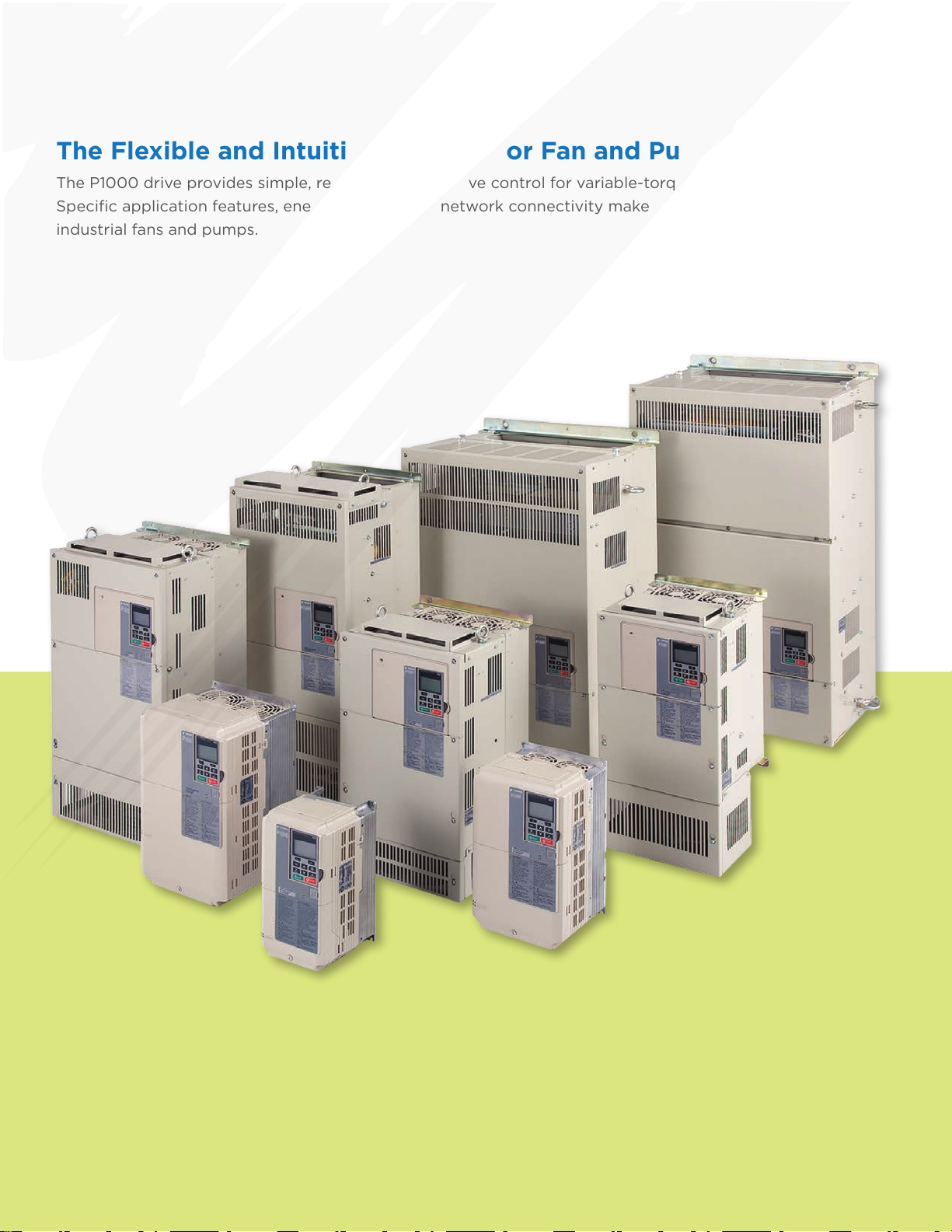
The Flexible and Intuitive Solution for Fan and Pump Applications.
The P1000 drive provides simple, reliable, cost-effective control for variable-torque loads through 1000 HP.
Specic application features, energy savings, and network connectivity make the P1000 a great choice for
industrial fans and pumps.
2
Contents
Features, Benets, and Specications 4
Drives and Accessories Selection 16
Mechanical Installation Planning 34
Electrical Installation Planning 39
Yaskawa Industrial Drives Family 42
Global Service Network
44
3
Features and Benets
Exceptional Quality
Enjoy peace of mind by knowing that you are considering a product from Yaskawa, the factory automation
controls company with the highest reputation for quality and reliability. Historically, Yaskawa drives have
demonstrated extremely high reliability with an average MTBF (mean time between failure) of 28 years or
more. The new 1000 series products take reliability to the next level with a calculated design life that is twice
as long as previous generations.
Highly Integrated Design results in fewer parts and interconnections,
reducing the number of failure points.
Component Derating extends the life of any single part by selecting higher
specications (e.g., voltage, current) than what a circuit requires for normal
operation.
Latest Generation IGBT Power Modules, capable of four times more thermal
cycles than previous designs.
Enhanced Short Circuit Detection and Self Diagnostics provide additional
protection against severe catastrophic conditions.
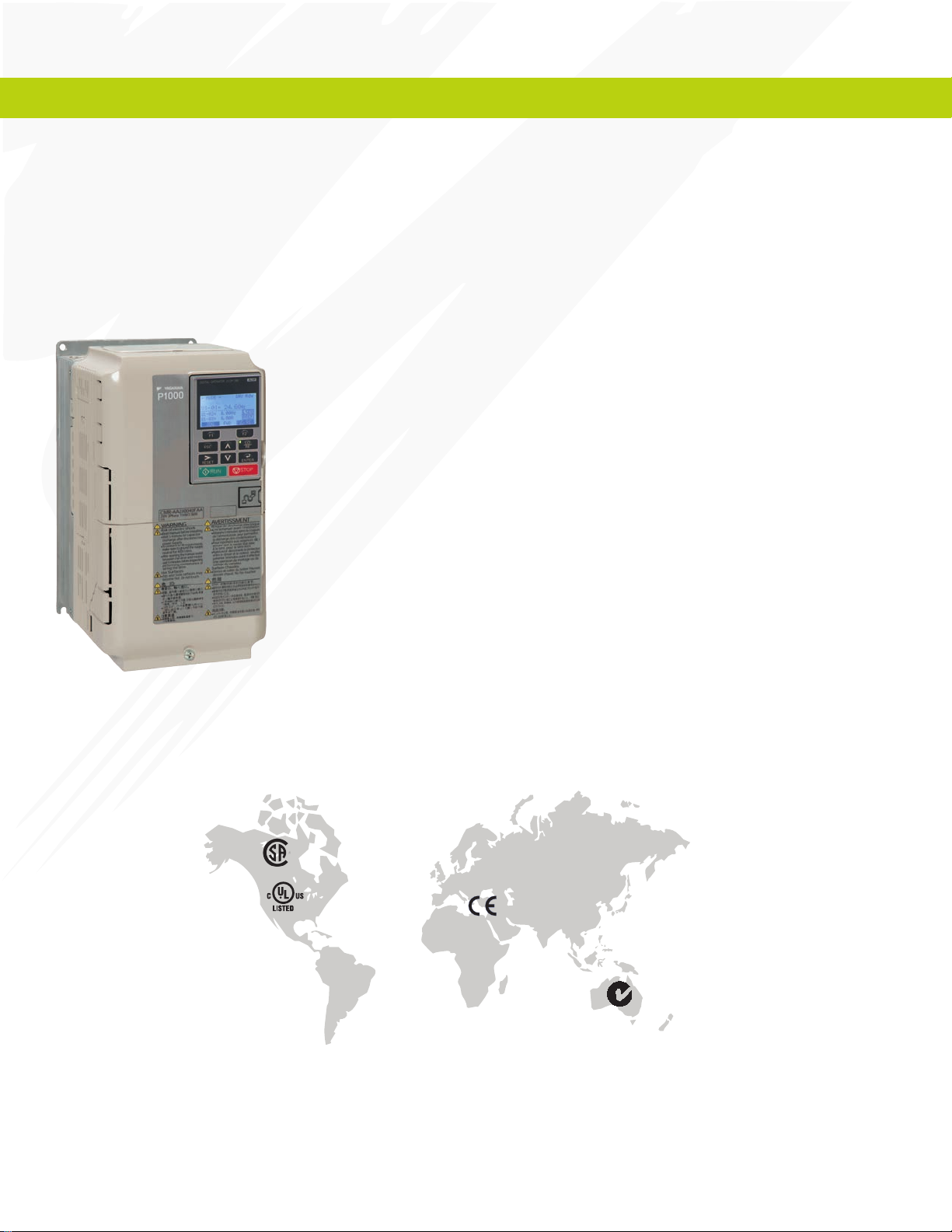
In addition, the P1000 is designed for use around the world, and carries agency certications for all
major geographical regions
4
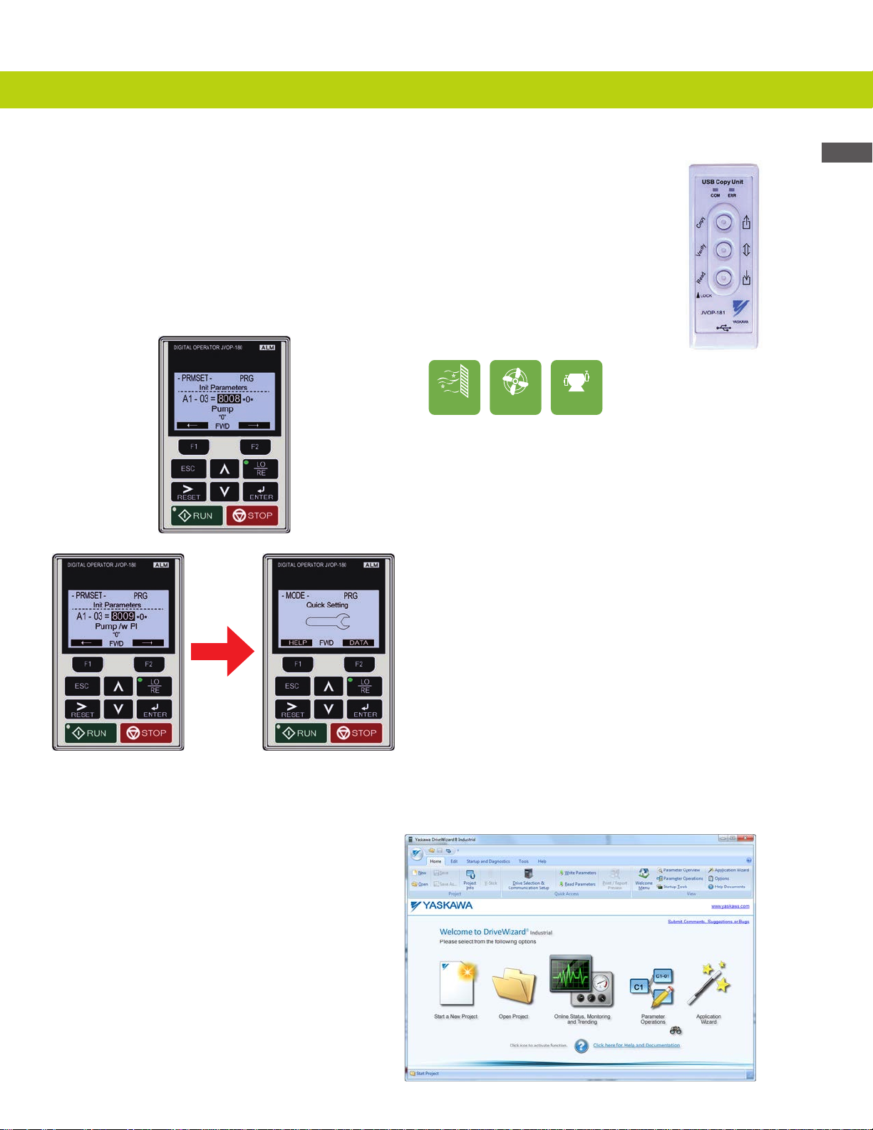
Easy to Apply and Maintain
The P1000 is supported by user-friendly conguration tools. For local eld access,
the keypad interface features a multi-language LCD display, parameter storage, and
application presets to make programming a simple task. It also has built-in memory for
backup purposes. In addition, a USB Copy Unit can be loaded with a drive’s program for
convenient portable transfer of conguration between an ofce environment and the
factory oor.
USB Copy Unit
HVAC
Fan
Pump
Fan and Pump Application
Presets
Start-up time has been reduced with
preprogrammed application presets
that allow for simple and easy start-up
by answering simple motor and
application information.
Application Presets: General Purpose;
Pump & Pump with PI Feedback Control;
Fan & Fan with PI Feedback Control
DriveWizard® computer software delivers conguration, monitoring, and trending functions enhanced
by direct connectivity through the P1000’s standard USB port.
Features, Benets, and Specications
• Online and Ofine Editing
• Application Wizard
• Monitoring and Diagnostic Panels
• Trend Recorder and Playback
• Network Congurator
• Multidrive Support
• Drive Flash Support
• Project Converter
• Report and Export Generation
• Search Engine
55
Features and Benets
Easy to Apply and Maintain
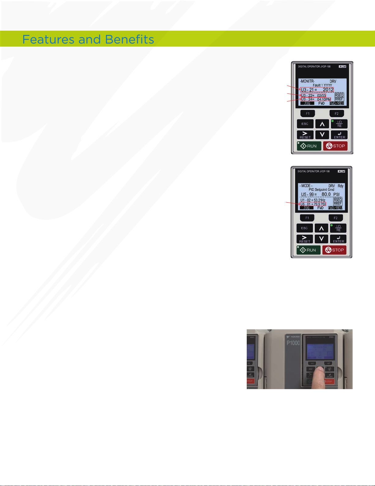
Real Time Clock (RTC)
Take advantage of the battery-backed clock that’s built into
the P1000’s keypad display. With this feature, the P1000 can
be controlled based on time of day, and can also provide timestamped event information.
PI Process Control
Two separate process control loops are embedded in the
P1000. One modies drive speed based on setpoint and sensor
feedback. A second control loop (with its own setpoint and
feedback inputs) can be output to control something completely
independent of the drive. Additionally, the P1000 provides a
24VDC, 150mA supply for applying power to sensors.
U3-21 = Year
U3-22 = Month/Date
U3-24 = Time of Fault
U5-01 = Transducer
Feedback
Selectable and User-Customizable Engineering Units
Allow for easy conguration of keypad display to match process
and feedback devices such as PSI, GPM, Feet.
Preventative Maintenance Monitors
Maximize production and intelligently schedule your
maintenance by making use of the P1000’s special monitors that
provide alarm information when a drive requires attention. Use
this information to trigger discrete outputs or send the status
across a network for upper level decision making.
• Cooling Fan Remaining Life
• IGBT (Power Module) Remaining Life
• Bus Capacitor Remaining Life
• Precharge Relay
• Drive (Heatsink) Temperature
6
6
Easy to Apply and Maintain
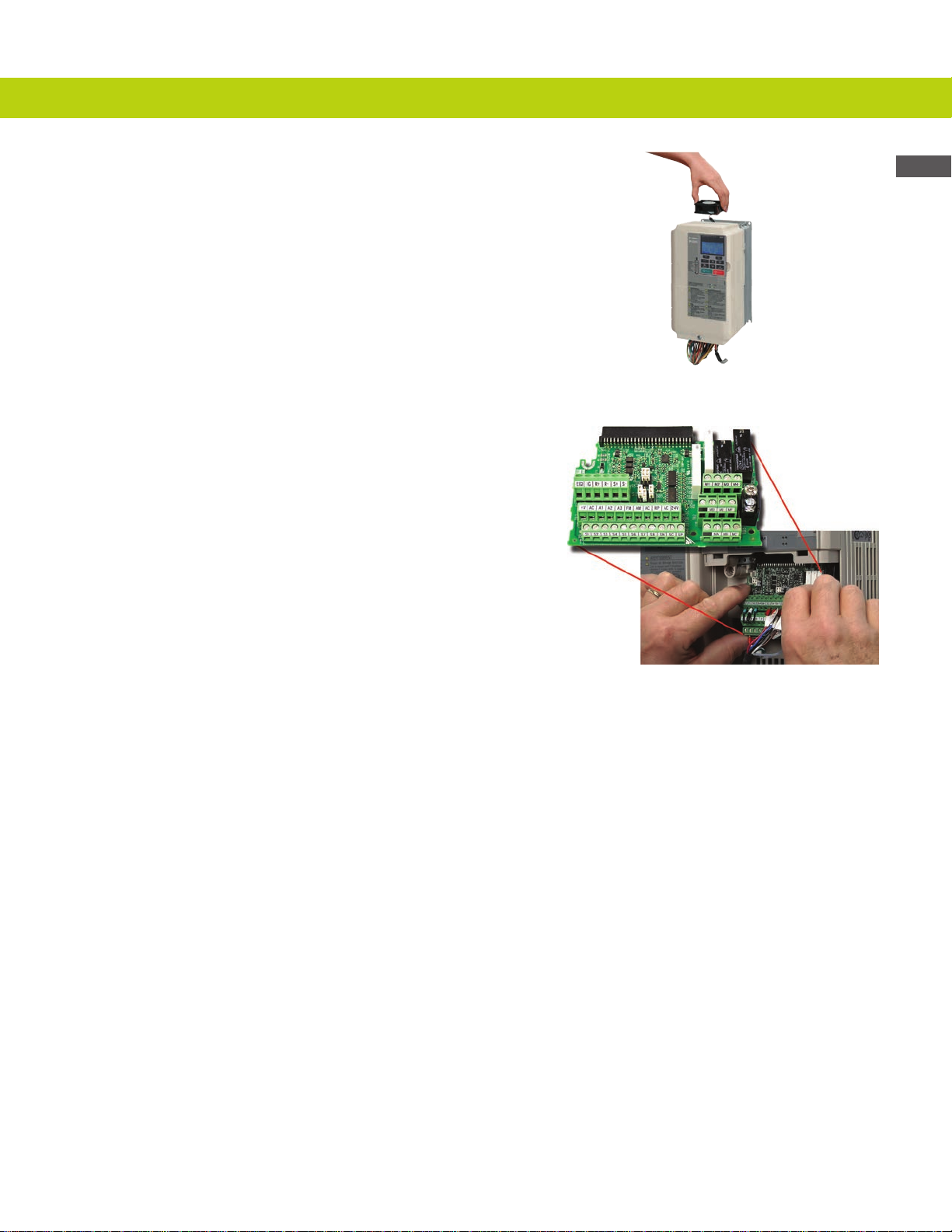
Highly Reliable and Easily Replaceable
Cooling Fans
• Improved location for convenient access, even when
mounted with heatsink external
• No tools required
• All ratings are 24Vdc powered
Removeable I/O Terminal Board with Drive
Backup Memory
• All parameter changes automatically saved to both main
control board and I/O board
• Leave I/O connected when replacing a drive
• Conguration is downloaded to replacement drive
• Reduces MTTR (Mean Time To Repair)
Features, Benets, and Specications
Underload Detection
Monitors the load and will stop the system in the event of a fan
belt or pump shaft failure.
Dynamic Noise Control
Monitors the load at all times and reduces the output voltage
automatically, reducing motor audible noise.
7
7
Features and Benets
Maximum Flexibility
Enjoy a signicant amount of standard control points. The P1000 can also expand to support popular
communication networks.
Standard I/O and Communications
• Digital Inputs (8)
• Analog Inputs (3)
• Pulse Inputs (1)
• Digital Outputs (4)
• 2 Form C Relays
• 2 Form A Relays
• Analog Outputs (2)
• RS485 Modbus RTU Communication
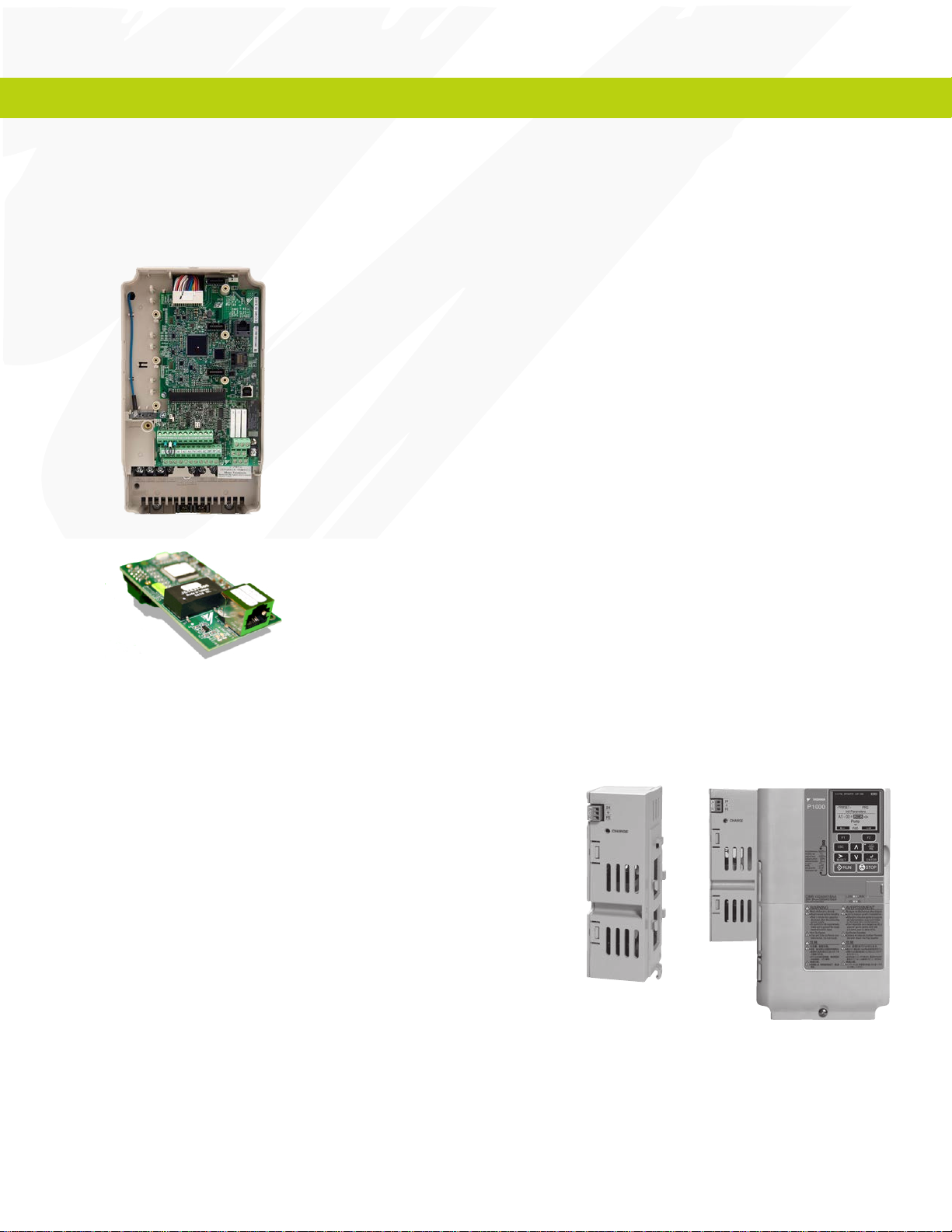
Expansion Capability
• Analog Output Module
(3 additional outputs)
• DeviceNet
• EtherNet/IP
• Modbus TCP/IP
• PROFIBUS-DP
• PROFINET
• BACnet
• Lonworks
• Metasys (N2)
• Apogee (P1)
Auxiliary Control Power Input
Keep your drives communicating over the network, even
while main power is removed. The Auxiliary Control Power
Input uses facility supplied 24Vdc to keep the drive’s control
and communication intact. Service your drive cabinets with
the benet of live control and communications without the
need for main power and associated Arc Flash protection.
8
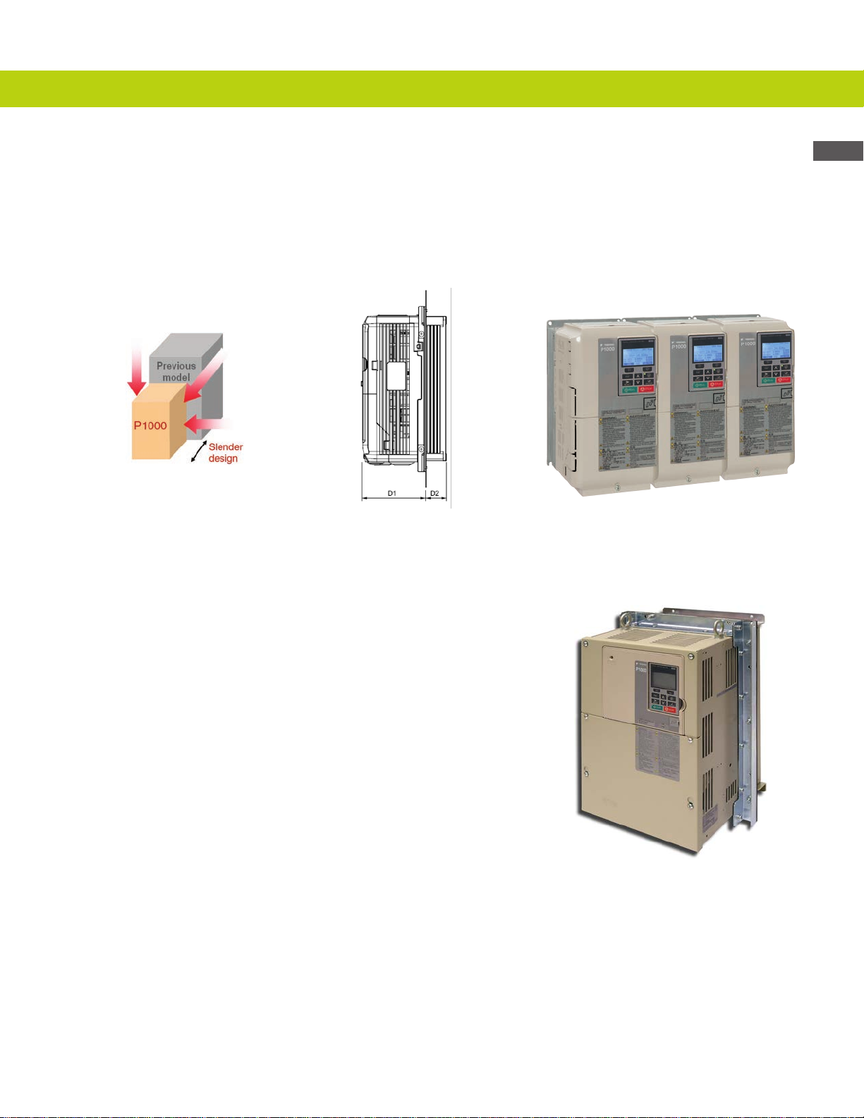
Maximum Flexibility
Space Saving Features
The P1000 offers world class power density resulting in an average size reduction of 30% as compared to
previous generations (see individual rating dimensions). In addition, even more cabinet space can be saved
by taking advantage of External Heatsink Mounting and Zero Side Clearance capability.
Features, Benets, and Specications
Physical Size Reduction External Heatsink Solution
(Side View)
Type 12 Flange Configuration
P1000 is available in all ratings as a Type 12 Flange conguration
that allows for mounting the drive with its heatsink out the back
of any Type 12 enclosure. This allows for the majority of the
drive’s heat to dissipate on the external side, while keeping the
enclosure small and sealed with Type 12 integrity.
Zero Side Clearance
(40°C max ambient)
9
Features and Benets
Power
supply
voltage
Motor
speed
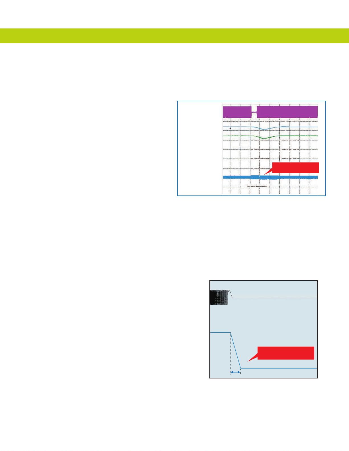
Trip-free Operation
Keep your applications running with features designed to avoid interruptions that are typical with
demanding load conditions.
• Optimal Decel automatically extends the
programmed deceleration time based on
the load condition and drive capability.
• Overvoltage Suppression limits the
DC bus voltage by modulating output
frequency to keep the drive out of the
regenerative region.
• Overload Fault Prevention responds
to heavy load conditions by adjusting
output frequency and voltage to keep the
drive’s current within operating limits.
• Momentary Power Loss Ride-Thru
puts the drive in standby mode
during transient power losses and
then automatically restarts, avoiding
potentially costly power related shut
down conditions.
• Bi-directional speed search allows the
drive to start into a rotating load by
quickly sensing the speed and direction
of the motor and then seamlessly
matching the drive’s output.
• For applications that can dissipate losses
in the motor, Over-Excitation Braking
and High Slip Braking are goodperforming, money-saving alternatives
to dynamic braking.
• In the event of a power loss, Kinetic
Energy Braking uses energy stored in the
rotating load to keep the drive powered
and bring the process to a controlled stop.
Power supply
voltage
Motor speed
Output frequency
Output current
1750 r/min
Speed Search
Uses regenerative energy to
keep the application running
Motor decelerates quickly to
protect the application
Controlled ramp to stop
Kinetic Energy Braking
10
Environmental
Reduce your energy bill and contribute towards a cleaner
environment with sustainable features designed into the
P1000.
Energy Savings Benefits of Variable Speed
Using variable speed on pumps and fans results is very
large energy savings as compared to other uid or air
control methods (valves, guide vanes, dampers, etc.).
Additionally, the P1000 provides even greater savings
with its Energy Saving Control that reduces unnecessary
magnetizing current at reduced speeds.
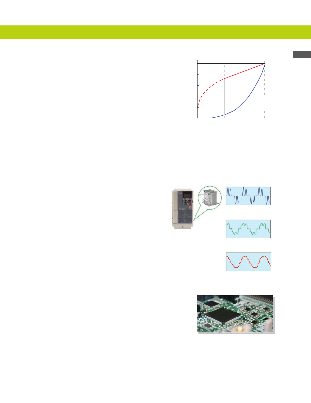
Power Quality Conscious
Built-in DC reactors (30 HP and larger) provide
input harmonics benet, and protection from input
disturbances.
100%
80&
60%
40%
POWER (%)
20%
0
Comparison of Power Requirements for
Variable Speed and Throttling method
BYPASS METHOD
THROTTLING
METHOD
POWER
SAVINGS
40 60 80 100
FLOW (%)
6-Pulse Drive without Reactor
(Approximately 88% THD)
6 Pulse Drive with Reactor
(Approximately 40% THD)
ADJUSTABLE
SPEED
METHOD
Features, Benets, and Specications
To further reduce harmonics reected back to the
utility power line, the P1000 is available with an
integrated 12-pulse diode bridge from 40 to 1000
HP @ 480VAC (also requires the use of an external
phase-shifting transformer).
Product Life Cycle Responsibility
The future of our environment and the earth’s natural
resources is very important to Yaskawa. The P1000
has been designed to minimize the use of harmful
materials (e.g. lead, mercury, cadmium, etc.) and
meets the requirements of RoHS (Restriction of
Hazardous Substances)
12 Pulse Drive
(Less than 15% THD)
11
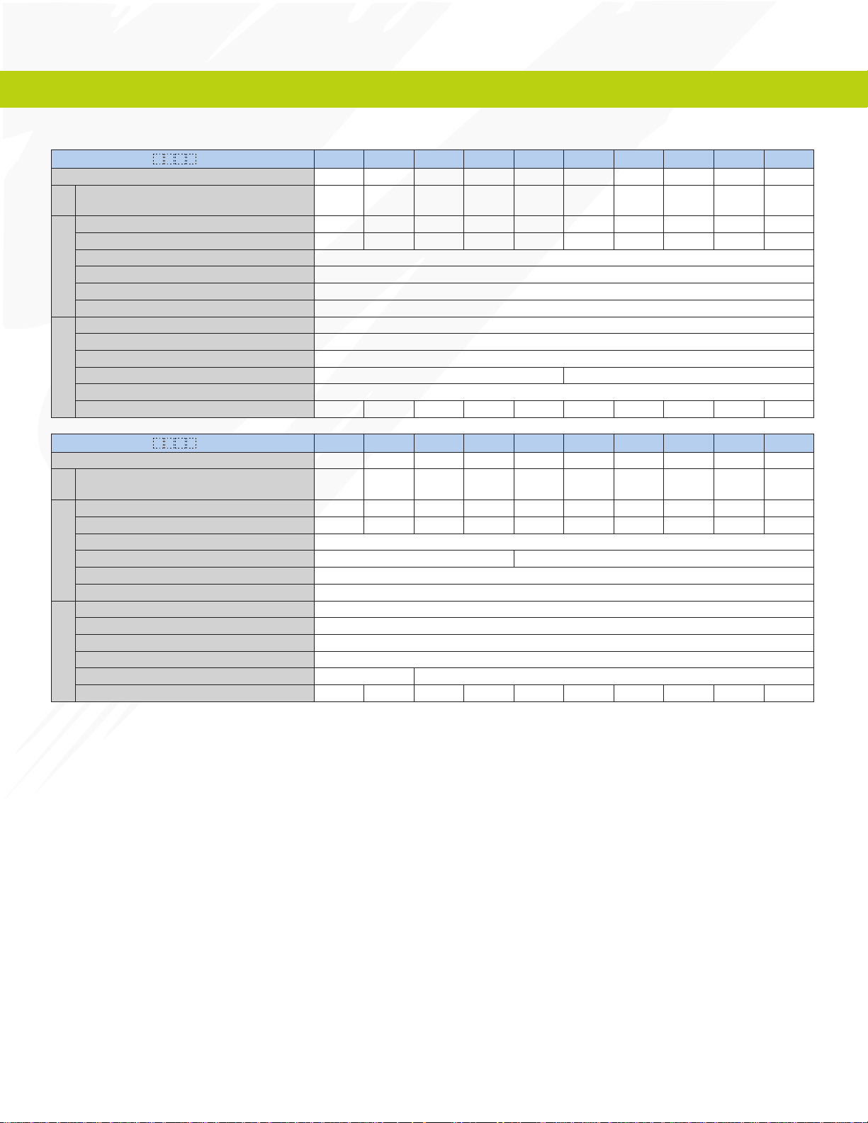
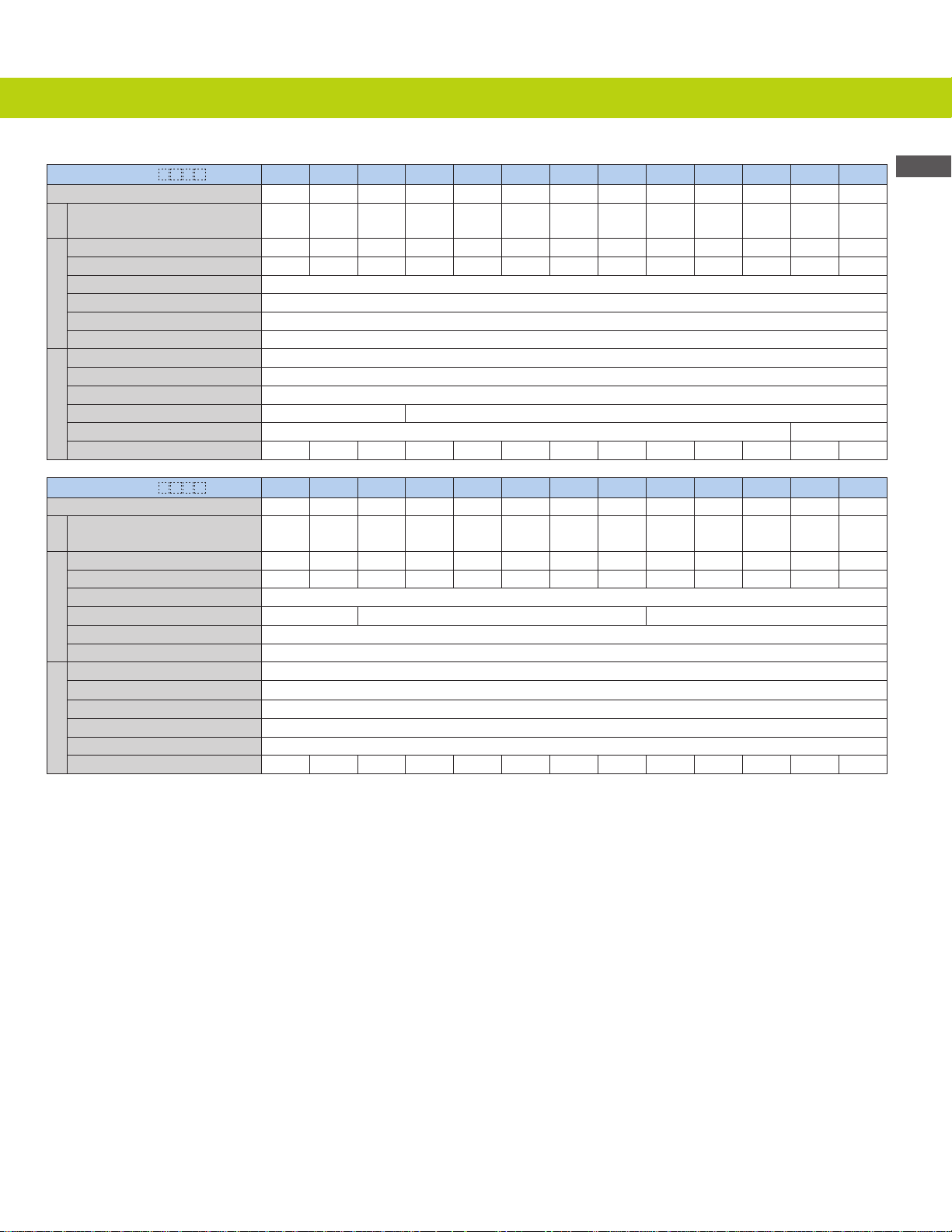
Specications
240V Class
Model CIMR-PU2A
*1
Max. Applicable Motor Capacity
Rated Input Current*2 A
Input
Rated Output Capacity
Rated Output Current
HP
*4,*5
kVA
*5
A
Overload Tolerance 120% of rated output current for 60 sec.
Carrier Frequency (User Adjustable) 2 to 15 kHz
Output
Max. Output Voltage Three-phase 200 to 240 V (relative to input voltage)
Max. Output Frequency 400 Hz
Rated Voltage/Rated Frequency Three-phase 200 to 240 Vac 50/60 Hz 270 to 340 Vdc
Allowable Voltage Fluctuation
Allowable Frequency Fluctuation ±5%
Fan No fan With fan
Power
DC Link Choke External Option
Power Supply kVA
0004 0006 0008 0010 0012 0018 0021 0030 0040 0056
0.75 1.5 2 3 3 5 7.5 10 15 20
3.9 7.3 8.8 10.8 13.9 18.5 24 37 52 68
1.3 2.3 3 3.7 4.6 6.7 8 11.4 15.2 21
3.5 6 8 9.6 12 17.5 21 30 40 56
-
15% to +10%
2.2 3.1 4.1 5.8 7.8 9.5 14 18 27 36
*3
Model CIMR-PU2A
*1
Max. Applicable Motor Capacity
Rated Input Current*2 A
Input
Rated Output Capacity
Rated Output Current
HP
*4,*5
kVA
*5
A
0069 0081 0110 0138 0169 0211 0250 0312 0360 0415
25 30 40 50 60 75 100 125 150 175
80 96 111 136 164 200 271 324 394 471
26 31 42 53 64 80 95 119 137 158
69 81 110 138 169 211 250 312 360 415
Overload Tolerance 120% of rated output current for 60 sec.
Carrier Frequency (User Adjustable) 2 to 15 kHz 2 to 10 kHz
Output
Max. Output Voltage Three-phase 200 to 240 V (relative to input voltage)
Max. Output Frequency 400 Hz (user-set)
Rated Voltage/Rated Frequency Three-phase 200 to 240 Vac 50/60 Hz 270 to 340 Vdc
Allowable Voltage Fluctuation
-
15% to +10%
*3
Allowable Frequency Fluctuation ±5%
Fan With fan
Power
DC Link Choke External Option Included
Power Supply kVA
44 52 51 62 75 91 124 148 180 215
*1. The motor capacity (HP) refers to a NEC rated 4-pole motor. The rated output current of the drive output amps should be equal to or greater than the
motor current. Select the appropriate capacity drive if operating the motor continuously above motor nameplate current.
*2. Assumes operation at the rated output current. Input current rating varies depending on the power supply transformer, input reactor, wiring
connections, and power supply impedance.
*3. Direct application of DC power is not presently supported by the P1000’s UL listing.
*4. Rated motor capacity is calculated with a rated output voltage of 230V.
*5. Carrier frequency is set to 2 kHz. Current derating is required in order to raise the carrier frequency.
12
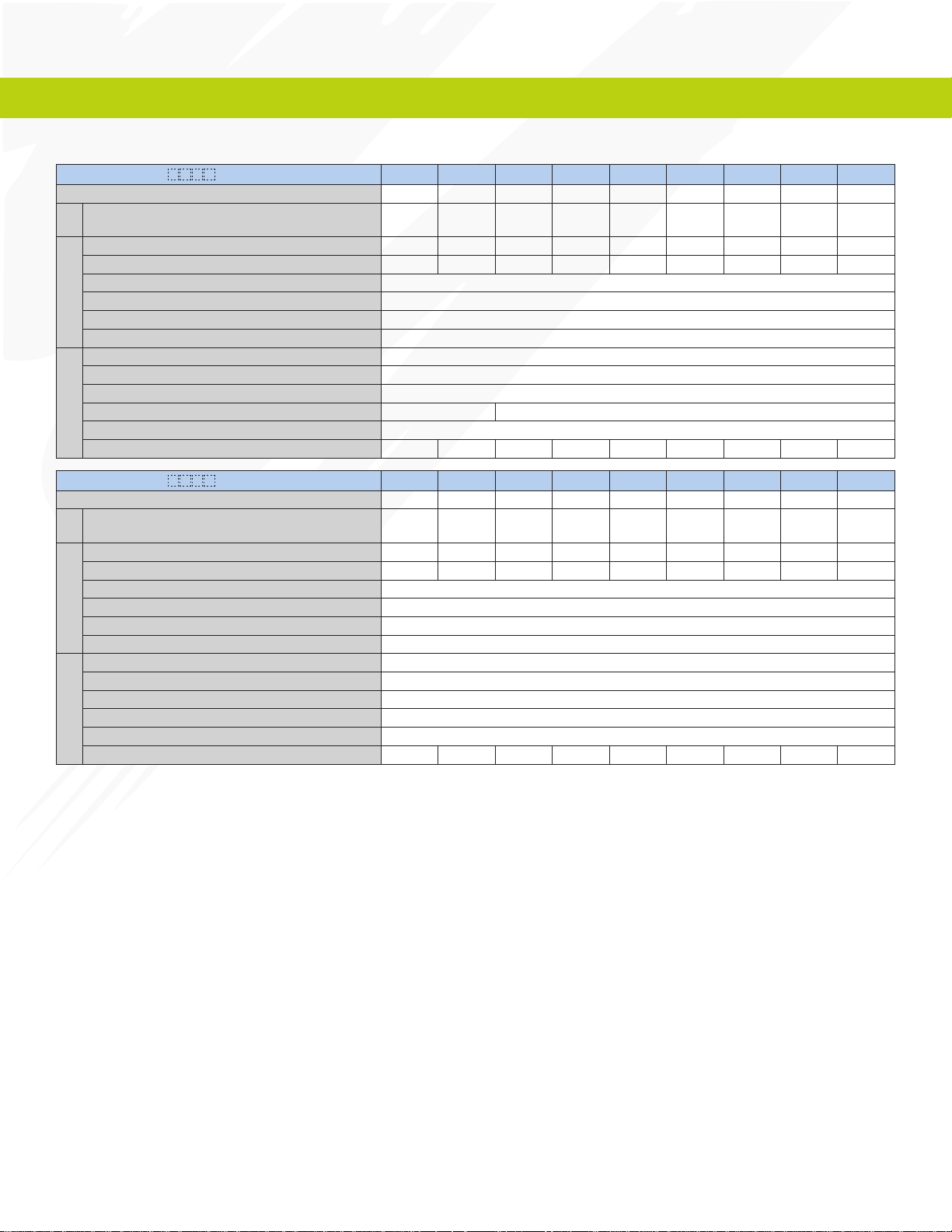
480V Class
Model CIMR-PU4A
Max. Applicable Motor Capacity
*1
HP
0002 0004 0005 0007 0009 0011 0018 0023 0031 0038 0044 0058 0072
1 2 3 3 5 7.5 10 15 20 25 30 40 50
Rated Input Current*2 A
Input
Rated Output Capacity
Rated Output Current
*4,*5
kVA
*5
A
2.1 4.3 5.9 8.1 9.4 14 20 24 38 51 60 58 71
1.6 3.1 4.1 5.3 6.7 8.5 13.3 17.5 24 29 34 44 55
2.1 4.1 5.4 6.9 8.8 11.1 17.5 23 31 38 44 58 72
Overload Tolerance 120% of rated output current for 60 sec.
Carrier Frequency (User Adjustable) 2 to 15 kHz
Output
Max. Output Voltage Three-phase 380 to 480 V (relative to input voltage)
Max. Output Frequency 400 Hz
Rated Voltage/Rated Frequency Three-phase 380 to 480 Vac 50/60 Hz 510 to 680 Vdc
Allowable Voltage Fluctuation
-
15% to +10%
*3
Allowable Frequency Fluctuation ±5%
Fan No fan With fan
Power
DC Link Choke External Option Included
Power Supply kVA
Model CIMR-PU4A
*1
Max. Applicable Motor Capacity
Rated Input Current*2 A
Input
Rated Output Capacity
Rated Output Current
HP
*4,*5
kVA
*5
A
2.3 4.3 6.1 8.1 10 14.5 19.4 28.4 37.5 46.6 54.9 53 64.9
0088 0103 0139 0165 0208 0250 0296 0362 0414 0515 0675 0930 1200
60 75 100 125 150 200 250 300 350 450 600 800 1000
86 105 142 170 207 248 300 346 410 465 657 922 1158
67 78 106 126 159 191 226 276 316 392 514 709 915
88 103 139 165 208 250 296 362 414 515 675 930 1200
Overload Tolerance 120% of rated output current for 60 sec.
Carrier Frequency (User Adjustable) 2 to 15 kHz 2 to 10 kHz 2 to 5 kHz
Output
Max. Output Voltage Three-phase 380 to 480 V (relative to input voltage)
Max. Output Frequency 400 Hz (user-set)
Rated Voltage/Rated Frequency Three-phase 380 to 480 Vac 50/60 Hz 510 to 680 Vdc
Allowable Voltage Fluctuation
-
15% to +10%
*3
Allowable Frequency Fluctuation ±5%
Fan With fan
Power
DC Link Choke Included
Power Supply kVA
78.6 96 130 156 189 227 274 316 375 425 601 843 601
*1. The motor capacity (HP) refers to a NEC rated 4-pole motor. The rated output current of the drive output amps should be equal to or greater than the
motor current. Select the appropriate capacity drive if operating the motor continuously above motor nameplate current.
*2. Assumes operation at the rated output current. Input current rating varies depending on the power supply transformer, input reactor, wiring
connections, and power supply impedance.
*3. Direct application of DC power is not presently supported by the P1000’s UL listing.
*4. Rated motor capacity is calculated with a rated output voltage of 460V.
*5. Carrier frequency is set to 2 kHz. Current derating is required in order to raise the carrier frequency.
Features, Benets, and Specications
13
Specications
600V Class
Model CIMR-PU5A
Max. Applicable Motor Capacity
Rated Input Current*2 A
Input
Rated Output Capacity
Rated Output Current
Overload Tolerance 120% of rated output current for 60 sec.
Carrier Frequency 2 to 15 kHz
Output
Max. Output Voltage Three-phase: 500 to 600 V (proportional to input voltage)
Max. Output Frequency 400 Hz
Rated Voltage/Rated Frequency Three-phase 500 to 600 Vac 50/60 Hz
Allowable Voltage Fluctuation
Allowable Frequency Fluctuation ±5%
Fan No fan With fan
Power
DC Link Choke External option
Power Supply kVA
*1
HP
*3,*4
kVA
*4
A
0003 0004 0006 0009 0011 0017 0022 0027 0032
2 3 5 7.5 10 15 20 25 30
3.6 5.1 8.3 12 16 23 31 38 45
2.7 3.9 6.1 9 11 17 22 27 32
2.7 3.9 6.1 9 11 17 22 27 32
-10 (-15) to +10%
4.1 5.8 9.5 14 18 26 35 43 51
Model CIMR-PU5A
Max. Applicable Motor Capacity
Rated Input Current*2 A
Input
Rated Output Capacity
Rated Output Current
Overload Tolerance 120% of rated output current for 60 sec.
Carrier Frequency 2 to 15 kHz
Output
Max. Output Voltage Three-phase: 500 to 600 V (proportional to input voltage)
Max. Output Frequency 400 Hz (user-set)
Rated Voltage/Rated Frequency Three-phase 500 to 600 Vac 50/60 Hz
Allowable Voltage Fluctuation
Allowable Frequency Fluctuation ±5%
Fan With fan
Power
DC Link Choke Included
Power Supply kVA
*1. The motor capacity (HP) refers to a NEC rated 4-pole motor. The rated output current of the drive output amps should be equal to or greater than the
motor current. Select the appropriate capacity drive if operating the motor continuously above motor nameplate current.
*2. Assumes operation at the rated output current. Input current rating varies depending on the power supply transformer, input reactor, wiring
connections, and power supply impedance.
*3. Rated motor capacity is calculated with a rated output voltage of 575V.
*4. Carrier frequency is set to 2 kHz. Current derating is required to raise the carrier frequency.
*1
HP
*3,*4
kVA
*4
A
0041 0052 0062 0077 0099 0125 0145 0192 0242
40 50 60 75 100 125 150 200 250
41 52 62 77 99 129 158 228 263
41 52 62 77 99 124 144 191 241
41 52 62 77 99 125 145 192 242
-10 (-15) to +10%
50 62 75 91 123
14

Common Specifications
Item Specications
Control Methods V/f Control (V/f)
Frequency Control Range
Frequency Accuracy
(Temperature Fluctuation)
Frequency Setting Resolution
Output Frequency Resolution
Frequency Setting Methods
Starting Torque
Speed Control Range
Accel/Decel Time 0.0 to 6000.0 s (4 selectable combinations of independent acceleration and deceleration settings)
Control Characteristics
<1>
<1>
V/f Characteristics User-selected programs and V/f preset patterns possible
Main Control Functions
Motor Protection Electronic thermal overload relay
Momentary Overcurrent Protection
Overload Protection Drive stops after 60 seconds at 120% of rated output current
Overvoltage Protection
Undervoltage Protection
Momentary Power Loss Ride-Thru
Heatsink Overheat Protection
Protection Function
Stall Prevention Stall Prevention is available during acceleration, deceleration, and during run.
Ground Fault Protection
Charge LED Remains lit until DC bus voltage falls below 50 V
Area of Use Indoors
Ambient Temperature
Humidity 95% RH or less (no condensation)
Storage Temperature
Altitude Up to 1000 meters without derating, up to 3000 m with output current and voltage derating
Operating Environment
Shock
Standards and Certications UL 508C, CSA C22.2, EN 61800-5-1
Protection Design IP00 enclosure, IP20/NEMA Type 1 enclosure
<1> The accuracy of these values depends on motor characteristics, ambient conditions, and drive settings. Specications may vary with different motorsand with changing motor
temperature. Contact Yaskawa for consultation.
<2> Overload protection may be triggered when operating with 150% of the rated output current if the output frequency is less than 6 Hz.
<3> May be shorter due to load conditions and motor speed.
<4> A separate Momentary Power Loss Ride-Thru Unit is required for models 2A0004 to 2A0056, 4A0002 to 4A0031, and 5A0003 to 5A0032 if the application needs to continue
running for up to 2 seconds during a momentary power loss.
<5> Ground protection cannot be provided when the impedance of the ground fault path is too low, or when the drive is powered up while a ground fault is present at the output.
<6> Removing the top protective cover or bottom conduit bracket from an IP20/NEMA Type 1 enclosure drive voids NEMA Type 1 protection while maintaining IP20 conformity.
This is applicable to models 2A0004 to 2A0211, 4A0002 to 4A0165, and 5A0003 to 5A0032.
0.01 to 400 Hz
Digital input: within ±0.01% of the max output frequency (-10 to +40 °C)
Analog input: within ±0.1% of the max output frequency (25 °C ±10 °C)
Digital inputs: 0.01 Hz
Analog inputs: 1/2048 of the maximum output frequency setting (11 bit plus sign)
0.001 Hz
0 to +10 V, 4 to 20 mA, Pulse Train Input, Network Communications, Keypad
V/f: 150% at 3 Hz
V/f: 1:40
Momentary Power Loss Ride-Thru, Speed Search, Overtorque/Undertorque Detection, 17 Step Speed (max), Accel/decel Switch, S-curve Accel/decel, 3-wire
Sequence, Auto-tuning (rotational, stationary tuning), Dwell, Cooling Fan on/off Switch, Slip Compensation, Torque Compensation, Frequency Jump, Upper/
lower Limits for Frequency Reference, DC Injection Braking at Start and Stop, Overexcitation Braking, High Slip Braking, PID Control (with sleep function),
Energy Saving Control, Modbus Comm. (RS-422/485 max, 115.2 kbps), Fault Restart, Application Presets, Removable Terminal Block with Parameter Backup
Function, Dynamic Noise Control.
Drive stops when output exceeds 170%
<2>
240V class: Faults when DC bus voltage exceeds approx. 410 V; 480V class: Faults when DC bus voltage exceeds approx. 820 V;
600V class: Faults when DC bus voltage exceeds approx. 1040 V.
240V class: Faults when DC bus voltage falls below approx. 190 V; 480V class: Faults when DC bus voltage falls below approx. 380 V;
600V class: Faults when DC bus voltage falls below approx. 475 V.
Stops modulating after 15 ms or longer power loss
<3> .
Resumes operation if power loss is less than 2 s (standard)
<4>
Thermistor
Electronic circuit protection
-10 to +50°C (Chassis Installation)
-10 to +40°C (Chassis with zero side clearance, or Type 1)
-
20 to +60˚C (short-term temperature during transportation)
10 to 20 Hz: 9.8 m/s
2.0 m/s
<5>
2
20 to 55 Hz: 5.9 m/s2 (2A0004 to 2A0211, 4A0002 to 4A0165, and 5A0003 to 5A0032)
2
(2A0250 to 2A0415 and 4A0208 to 4A0675)
<6>
Features, Benets, and Specications
15
 Loading...