

Page 1

NX100 OPTIONS
1/210
INSTRUCTIONS
FOR INDEPENDENT/COORDINATED CONTROL FUNCTION
Upon receipt of the product and prior to initial operation, read these instructions thoroughly, and retain
for future reference.
MOTOMAN INSTRUCTIONS
MOTOMAN- INSTRUCTIONS
NX100 INSTRUCTIONS
NX100 OPERATOR’S MANUAL
NX100 MAINTENANCE MANUAL
The NX100 operator’s manuals above correspond to specific usage.
Be sure to use the appropriate manual.
Part Number: 149648-1CD
Revision: 4
MANUAL NO. RE-CKI-A443
4
Page 2

MANDATORY
CAUTION
2/210
• This manual explains the independent/coordinated control function of
the NX100 system and general operations. Read this manual carefully
and be sure to understand its contents before handling the NX100.
• General items related to safety are listed in Chapter 1: Safety of the
NX100 Instructions. To ensure correct and safe operation, carefully
read the NX100 Instructions before reading this manual.
• Some drawings in this manual are shown with the protective covers or
shields removed for clarity. Be sure all covers and shields are replaced
before operating this product.
• The drawings and photos in this manual are representative examples
and differences may exist between them and the delivered product.
• Y ASKAWA may modify this model without notice when necessary due to
product improvements, modifications, or changes in specifications. If
such modification is made, the manual number will also be revised.
• If your copy of the manual is damaged or lost, contact a YASKAWA representative to order a new copy. The representatives are listed on the
back cover. Be sure to tell the representative the manual number listed
on the front cover.
• YASK A WA is not responsible for incidents arising from unauthorized
modification of its products. Unauthorized modification voids your product’s warranty.
ii
Page 3

Notes for Safe Operation
WARNING
CAUTION
MANDATORY
PROHIBITED
NOTE
3/210
Read this manual carefully before installation, operation, maintenance, or inspection of the
NX100.
In this manual, the Notes for Safe Operation are classified as “WARNING,” “CAUTION,”
“MANDATORY,” or ”PROHIBITED.”
Indicates a potentially hazardous situation which, if not avoided,
could result in death or serious injury to personnel.
Indicates a potentially hazardous situation which, if not avoided,
could result in minor or moderate injury to personnel and damage to equipment. It may also be used to alert against unsafe
practices.
Always be sure to follow explicitly the items listed under this
heading.
Must never be performed.
Even items described as “CAUTION” may result in a serious accident in some situations. At
any rate, be sure to follow these important items.
To ensure safe and efficient operation at all times, be sure to follow all instructions, even if
not designated as “CAUTION” and “WARNING.”
iii
Page 4
WARNING
TURN
4/210
• Before operating the manipulator, check tha t servo power is turned OFF
when the emergency stop buttons on the front door of the NX100 and
programming pendant are pressed.
When the servo power is turned OFF, the SERVO ON LED on the programming pendant is turned OFF.
Injury or damage to machinery may result if the emergency stop circuit cannot stop the
manipulator during an emergency. The manipulator should not be used if the emergency
stop buttons do not function.
Emergency Stop Button
• Once the emergency stop button is released, clear the cell of all items
which could interfere with the operation of the manipulator. Then turn
the servo power ON.
Injury may result from unintentional or unexpected manipulator motion.
Release of Emergency Stop
• Observe the following precautions when performing teaching operations
within the P-point maximum envelope of the manipulator :
- View the manipulator from the front whenever possible.
- Always follow the predetermined oper ating procedure.
- Ensure that you have a safe place to retreat in case of emergency.
Improper or unintended manipulator operation may result in injury.
• Confirm that no persons are present in the P-point maximum envelope of
the manipulator and that you are in a safe location before:
- Turning ON the NX100 power
- Moving the manipulator with the programming pendant
- Running the system in the check mode
- Performing automatic operations
Injury may result if anyone enters the P-point maximum envelope of the manipulator during operation. Always press an emergency stop button immediately if there are problems.The emergency stop buttons are located on the right of the front door of the NX100
and the programming pendant.
iv
Page 5
• Perform the following inspection procedures prior to conducting manip-
CAUTION
5/210
ulator teaching. If problems are found, repair them immediately, and be
sure that all other necessary processing has been performed.
-Check for problems in manipulator movement.
-Check for damage to insulation and sheathing of external wires.
• Always return the programming pendant to the hook on the NX100 cabinet after use.
The programming pendant can be damaged if it is left in the P-point maximum envelope
of the manipulator, on the floor, or near fixtures.
• Read and understand the Explanation of Warning Labels in the NX100
Instructions before operating the manipulator.
Definition of Terms Used Often in Th is Manual
The MOTOMAN manipulator is the YASKAWA industrial robot product.
The manipulator usually consists of the controller, the programming pendant, and supply
cables.
In this manual, the equipment is designated as follows:
Equipment Manual Designation
NX100 Controller NX100
NX100 Programming Pendant Programming Pendant
v
Page 6
PAGE
GO BACK
6/210
Descriptions of the programming pendant keys, buttons, and displays are shown as follows:
Equipment Manual Designation
Programming
Pendant
Character Keys The keys which have characters printed on them are
denoted with [ ].
ex. [ENTER]
Symbol Keys The keys which have a symbol printed on them are
not denoted with [ ] but depicted with a small picture.
ex. page key
The cursor key is an exception, and a picture is not
shown.
Axis Keys
Numeric Keys
Keys pressed
simultaneously
Displays The menu displayed in the programming pendant is
“Axis Keys” and “Numeric Keys” are generic names
for the keys for axis operation and number input.
When two keys are to be pressed simultaneously,
the keys are shown with a “+” sign between them,
ex. [SHIFT]+[COORD]
denoted with { }.
ex. {JOB}
Description of the Operation Procedure
In the explanation of the operation procedure, the expression "Select • • • " means that the
cursor is moved to the object item and the SELECT key is pressed, or that the item is directly
selected by touching the screen.
Registered Trademark
In this manual, names of companies, corporations, or products are trademarks, registered
trademarks, or brand names for each company or corporation. The indications of (R) and TM
are omitted.
vi
Page 7

1 Independent/Coordinated Control Function
7/210
1.1 Coordinated Control
1.2 Independent Control
. . . . . . . . . . . . . . . . . . . . . . . . . . . . . . . .1-1
. . . . . . . . . . . . . . . . . . . . . . . . . . . . . . . .1-2
2 Coordinated Positioner System
2.1 Outline
2.2 Function Keys
2.2.1 Arc Welding Application. . . . . . . . . . . . . . . . . . . . . . . . . . . . . . .2-2
2.2.2 General Application . . . . . . . . . . . . . . . . . . . . . . . . . . . . . . . . . .2-4
2.3 Example of Job Teaching
2.4 System Setup
2.4.1 Registering Group Combination . . . . . . . . . . . . . . . . . . . . . . . .2-7
2.4.2 Calibration between Manipulator and Station . . . . . . . . . . . . .2-10
2.5 JOB CONTENT Window
. . . . . . . . . . . . . . . . . . . . . . . . . . . . . . . . . . . . . . . . . . . . .2-1
. . . . . . . . . . . . . . . . . . . . . . . . . . . . . . . . . . . . . .2-2
. . . . . . . . . . . . . . . . . . . . . . . . . . . . . . . . . . . . . .2-7
Calibration Tool Setting . . . . . . . . . . . . . . . . . . . . . . . . . . . .2-10
Teaching Positions for Calibration. . . . . . . . . . . . . . . . . . . .2-11
Calibration . . . . . . . . . . . . . . . . . . . . . . . . . . . . . . . . . . . . . .2-14
. . . . . . . . . . . . . . . . . . . . . . . . . . .2-17
. . . . . . . . . . . . . . . . . . . . . . . . . . .2-6
2.6 Synchronized/Single
2.6.1 Synchronized. . . . . . . . . . . . . . . . . . . . . . . . . . . . . . . . . . . . . .2-18
2.6.2 Single. . . . . . . . . . . . . . . . . . . . . . . . . . . . . . . . . . . . . . . . . . . .2-19
2.7 Selecting Axis to be Handled
2.7.1 When There is an Edit Job . . . . . . . . . . . . . . . . . . . . . . . . . . .2-20
2.7.2 When There is No Edit Job . . . . . . . . . . . . . . . . . . . . . . . . . . .2-20
2.8 Registering Job
2.9 Registering Move Instruction (S)MOV+MOVJ
2.9.1 Operating Master Side (Station) . . . . . . . . . . . . . . . . . . . . . . .2-22
2.9.2 Operating Slave Side (Manipulator) . . . . . . . . . . . . . . . . . . . .2-23
2.10 Registering Reference Point Instruction
(SREFP)
3 Jigless System
3.1 Outline
3.2 Specific Keys
. . . . . . . . . . . . . . . . . . . . . . . . . . . . . . .2-18
. . . . . . . . . . . . . . . . . . . . . .2-20
. . . . . . . . . . . . . . . . . . . . . . . . . . . . . . . . . . . .2-21
. . . .2-22
. . . . . . . . . . . . . . . . . . . . . . . . . . . . . . . . . . . . . . . . .2-24
. . . . . . . . . . . . . . . . . . . . . . . . . . . . . . . . . . . . . . . . . . . . .3-1
. . . . . . . . . . . . . . . . . . . . . . . . . . . . . . . . . . . . . . .3-2
3.3 Opening and Closing Handling Tool
3.4 Example of Teaching Job
3.5 System Setup
3.5.1 Registering Group Combination . . . . . . . . . . . . . . . . . . . . . . . .3-6
3.5.2 Calibration between Manipulators . . . . . . . . . . . . . . . . . . . . . . .3-8
. . . . . . . . . . . . . . . . . . . . . . . . . . . . . . . . . . . . . .3-6
vii
. . . . . . . . . . . . . . . . . . . . . . . . . . .3-5
. . . . . . . . . . . . . . . .3-4
Page 8

8/210
Calibration Tool Setting . . . . . . . . . . . . . . . . . . . . . . . . . . . . 3-8
Teaching Position for Calibration . . . . . . . . . . . . . . . . . . . . . 3-9
Calibration. . . . . . . . . . . . . . . . . . . . . . . . . . . . . . . . . . . . . . 3-10
3.6 Job Content Display
3.7 Synchronized/Single
3.7.1 Synchronized . . . . . . . . . . . . . . . . . . . . . . . . . . . . . . . . . . . . . 3-14
3.7.2 Single . . . . . . . . . . . . . . . . . . . . . . . . . . . . . . . . . . . . . . . . . . . 3-15
3.8 Selecting Axis to be Handled
3.8.1 When There is an Edit Job . . . . . . . . . . . . . . . . . . . . . . . . . . . 3-16
3.8.2 When There is No Edit Job . . . . . . . . . . . . . . . . . . . . . . . . . . . 3-16
3.9 Registering Job
. . . . . . . . . . . . . . . . . . . . . . . . . . . . . . . 3-13
. . . . . . . . . . . . . . . . . . . . . . . . . . . . . . 3-14
. . . . . . . . . . . . . . . . . . . . . 3-16
. . . . . . . . . . . . . . . . . . . . . . . . . . . . . . . . . . . 3-17
3.10 Registering Move Instruction (S)MOV+MOV
3.10.1 Operating Master Side (Workpiece) . . . . . . . . . . . . . . . . . . . 3-18
3.10.2 Operating Slave Side (Torch) . . . . . . . . . . . . . . . . . . . . . . . . 3-19
3.11 Registering Reference Point Instruction
(SREFP)
3.12 Registering Handling Instructions
3.13 Other Convenient Features
3.13.1 Example of Movement . . . . . . . . . . . . . . . . . . . . . . . . . . . . . 3-22
3.13.2 Operation Method. . . . . . . . . . . . . . . . . . . . . . . . . . . . . . . . . 3-23
3.13.3 Manipulator Movement . . . . . . . . . . . . . . . . . . . . . . . . . . . . . 3-24
Basic axes . . . . . . . . . . . . . . . . . . . . . . . . . . . . . . . . . . . . . 3-24
Wrist axes . . . . . . . . . . . . . . . . . . . . . . . . . . . . . . . . . . . . . . 3-25
Synchronized/Single . . . . . . . . . . . . . . . . . . . . . . . . . . . . . . 3-25
. . . . . . . . . . . . . . . . . . . . . . . . . . . . . . . . . . . . . . . . 3-20
. . . . . . . . . . . . . . . . 3-21
. . . . . . . . . . . . . . . . . . . . . . 3-22
.3-18
4 Twin Synchronous System
4.1 Outline
4.2 Function Keys
4.2.1 Arc Welding Application . . . . . . . . . . . . . . . . . . . . . . . . . . . . . . 4-3
4.2.2 General Application . . . . . . . . . . . . . . . . . . . . . . . . . . . . . . . . . 4-5
4.3 Job Configuration
4.4 Leader and Follower
4.5 Synchronizing with TSYNC
4.6 Job Example
4.7 JOB CONTENT Window
4.8 Synchronized/Single
4.8.1 Synchronized/Single Movement Between Station
4.8.2 Job Synchronized Mode for Subtask 1 and 2 . . . . . . . . . . . . . 4-15
. . . . . . . . . . . . . . . . . . . . . . . . . . . . . . . . . . . . . . . . . . . . . 4-1
. . . . . . . . . . . . . . . . . . . . . . . . . . . . . . . . . . . . . . 4-3
. . . . . . . . . . . . . . . . . . . . . . . . . . . . . . . . . . 4-6
. . . . . . . . . . . . . . . . . . . . . . . . . . . . . . . . . . . . . . 4-11
and Manipulator . . . . . . . . . . . . . . . . . . . . . . . . . . . . . . . . . . . 4-13
Synchronized . . . . . . . . . . . . . . . . . . . . . . . . . . . . . . . . . . . 4-13
Single . . . . . . . . . . . . . . . . . . . . . . . . . . . . . . . . . . . . . . . . . 4-14
. . . . . . . . . . . . . . . . . . . . . . . . . . . . . . . 4-7
. . . . . . . . . . . . . . . . . . . . . . . . . 4-8
. . . . . . . . . . . . . . . . . . . . . . . . . . 4-12
. . . . . . . . . . . . . . . . . . . . . . . . . . . . . . 4-13
viii
Page 9

9/210
4.9 Selecting Axis to be Handled
4.9.1 When There is an Edit Job . . . . . . . . . . . . . . . . . . . . . . . . . . .4-17
4.9.2 When There is No Edit Job . . . . . . . . . . . . . . . . . . . . . . . . . . .4-17
4.10 Registering Job
. . . . . . . . . . . . . . . . . . . . . . . . . . . . . . . . . .4-18
. . . . . . . . . . . . . . . . . . . . . .4-17
4.11 Registering Move Instruction (S)MOV+MOVJ
4.11.1 Operating Master Side (Station) . . . . . . . . . . . . . . . . . . . . . .4-19
4.11.2 Operating Slave Side (Manipulator) . . . . . . . . . . . . . . . . . . .4-20
4.12 Registering Reference Point Instruction
(SREFP)
4.13 Switching Tasks
4.14 Creating a Job in a Subtask - Method 1 and 2
. . . . . . . . . . . . . . . . . . . . . . . . . . . . . . . . . . . . . . . . .4-21
. . . . . . . . . . . . . . . . . . . . . . . . . . . . . . . . .4-22
. . . .4-23
4.15 Method 1: Copy One Subtask Job and
Create Another Job
4.15.1 Procedure . . . . . . . . . . . . . . . . . . . . . . . . . . . . . . . . . . . . . . .4-24
4.15.2 Teaching and Mirror Shift . . . . . . . . . . . . . . . . . . . . . . . . . . .4-25
Converting . . . . . . . . . . . . . . . . . . . . . . . . . . . . . . . . . . . . . .4-25
Jobs Not to be Converted . . . . . . . . . . . . . . . . . . . . . . . . . .4-27
Group Axes for Conversion . . . . . . . . . . . . . . . . . . . . . . . . .4-27
Position Type Variables. . . . . . . . . . . . . . . . . . . . . . . . . . . .4-27
Parameter . . . . . . . . . . . . . . . . . . . . . . . . . . . . . . . . . . . . . .4-27
4.15.3 Correcting Positional Dislocation . . . . . . . . . . . . . . . . . . . . .4-28
Setting the Items for Conversion . . . . . . . . . . . . . . . . . . . . .4-28
Setting the Shift Value. . . . . . . . . . . . . . . . . . . . . . . . . . . . .4-29
Executing Conversion . . . . . . . . . . . . . . . . . . . . . . . . . . . . .4-32
. . . . . . . . . . . . . . . . . . . . . . . . . . . . . .4-24
. .4-19
4.16 Method 2: Perform Teaching for
Each Manipulator
4.16.1 Procedure . . . . . . . . . . . . . . . . . . . . . . . . . . . . . . . . . . . . . . .4-33
4.16.2 Teaching using Master Task . . . . . . . . . . . . . . . . . . . . . . . . .4-34
4.16.3 Teaching using SUPERVISORY Window. . . . . . . . . . . . . . .4-36
4.17 Job in Master Task
4.18 Confirming Operation
4.18.1 Procedure . . . . . . . . . . . . . . . . . . . . . . . . . . . . . . . . . . . . . . .4-41
4.18.2 Precautions for Confirming Operation. . . . . . . . . . . . . . . . . .4-42
Stops during Operation . . . . . . . . . . . . . . . . . . . . . . . . . . . .4-42
When “Multi-job operation mode” is Set
in the TEACHING CONDITION Window . . . . . . . . . . . . . . .4-43
4.19 Playback
4.19.1 Start. . . . . . . . . . . . . . . . . . . . . . . . . . . . . . . . . . . . . . . . . . . .4-44
4.19.2 Automatic Correction of Shift Value . . . . . . . . . . . . . . . . . . .4-45
. . . . . . . . . . . . . . . . . . . . . . . . . . . . . . . . . . . . . . . . .4-44
. . . . . . . . . . . . . . . . . . . . . . . . . . . . . . . .4-33
. . . . . . . . . . . . . . . . . . . . . . . . . . . . . . .4-39
. . . . . . . . . . . . . . . . . . . . . . . . . . . .4-41
ix
Page 10

10/210
5 Triple Synchronous System
5.1 Outline
5.2 Function Keys
5.2.1 Arc Welding Application . . . . . . . . . . . . . . . . . . . . . . . . . . . . . . 5-3
5.2.2 General Application . . . . . . . . . . . . . . . . . . . . . . . . . . . . . . . . . 5-5
5.3 Job Configuration
5.4 Leader and Follower
5.5 Synchronizing with TSYNC
5.6 Job Example
5.7 JOB CONTENT Window
5.8 Synchronized/Single
5.8.1 Synchronized/Single Movement Between Station and
5.8.2 Job Synchronized Mode for Subtask 1, 2, and 3 . . . . . . . . . . 5-16
5.9 Selecting Axis to be Handled
5.9.1 When There is an Edit Job . . . . . . . . . . . . . . . . . . . . . . . . . . . 5-18
5.9.2 When There is No Edit Job . . . . . . . . . . . . . . . . . . . . . . . . . . . 5-18
. . . . . . . . . . . . . . . . . . . . . . . . . . . . . . . . . . . . . . . . . . . . . 5-1
. . . . . . . . . . . . . . . . . . . . . . . . . . . . . . . . . . . . . . 5-3
. . . . . . . . . . . . . . . . . . . . . . . . . . . . . . . . . . 5-7
. . . . . . . . . . . . . . . . . . . . . . . . . . . . . . . 5-8
. . . . . . . . . . . . . . . . . . . . . . . . . 5-8
. . . . . . . . . . . . . . . . . . . . . . . . . . . . . . . . . . . . . . 5-12
. . . . . . . . . . . . . . . . . . . . . . . . . . 5-13
. . . . . . . . . . . . . . . . . . . . . . . . . . . . . . 5-14
Manipulator . . . . . . . . . . . . . . . . . . . . . . . . . . . . . . . . . . . . . . 5-14
Synchronized . . . . . . . . . . . . . . . . . . . . . . . . . . . . . . . . . . . 5-14
Single . . . . . . . . . . . . . . . . . . . . . . . . . . . . . . . . . . . . . . . . . 5-15
. . . . . . . . . . . . . . . . . . . . . 5-18
5.10 Registering Job
5.11 Registering Move Instruction (S)MOV+MOVJ
5.11.1 Operating Master Side (Station). . . . . . . . . . . . . . . . . . . . . . 5-20
5.11.2 Operating Slave Side (Manipulator) . . . . . . . . . . . . . . . . . . . 5-21
. . . . . . . . . . . . . . . . . . . . . . . . . . . . . . . . . . 5-19
. . 5-20
5.12 Registering Reference Point Instruction
(SREFP)
5.13 Changing Tasks
5.14 Creating a Job in a Subtask - Method 1 and 2
. . . . . . . . . . . . . . . . . . . . . . . . . . . . . . . . . . . . . . . . 5-22
. . . . . . . . . . . . . . . . . . . . . . . . . . . . . . . . . 5-23
. . . . 5-23
5.15 Method 1: Copy One Subtask Job and
Create Other Two Jobs
5.15.1 Procedure. . . . . . . . . . . . . . . . . . . . . . . . . . . . . . . . . . . . . . . 5-25
5.15.2 Teaching and Mirror Shift . . . . . . . . . . . . . . . . . . . . . . . . . . . 5-26
Converting . . . . . . . . . . . . . . . . . . . . . . . . . . . . . . . . . . . . . 5-26
Jobs Not to be Converted . . . . . . . . . . . . . . . . . . . . . . . . . . 5-28
Group Axes for Conversion . . . . . . . . . . . . . . . . . . . . . . . . 5-28
Position Type Variables . . . . . . . . . . . . . . . . . . . . . . . . . . . 5-28
Parameter . . . . . . . . . . . . . . . . . . . . . . . . . . . . . . . . . . . . . . 5-28
5.15.3 Correcting Positional Dislocation . . . . . . . . . . . . . . . . . . . . . 5-29
Setting the Items for Conversion . . . . . . . . . . . . . . . . . . . . 5-29
Setting the Shift Value . . . . . . . . . . . . . . . . . . . . . . . . . . . . 5-30
Executing Conversion. . . . . . . . . . . . . . . . . . . . . . . . . . . . . 5-33
. . . . . . . . . . . . . . . . . . . . . . . . . . 5-25
5.16 Method 2: Perform Teaching for
Each Manipulator
. . . . . . . . . . . . . . . . . . . . . . . . . . . . . . . . 5-34
x
Page 11

5.16.1 Procedure . . . . . . . . . . . . . . . . . . . . . . . . . . . . . . . . . . . . . . .5-34
11/210
5.16.2 Teaching using Master Task . . . . . . . . . . . . . . . . . . . . . . . . .5-34
5.16.3 Teaching using SUPERVISORY Window. . . . . . . . . . . . . . .5-37
5.17 Job in Master Task
5.18 Confirming Operation
5.18.1 Procedure . . . . . . . . . . . . . . . . . . . . . . . . . . . . . . . . . . . . . . .5-42
5.18.2 Precautions for Confirming Operation. . . . . . . . . . . . . . . . . .5-43
Stops during Operation . . . . . . . . . . . . . . . . . . . . . . . . . . . .5-43
When “Multi-job operation mode” is Set in the
TEACHING CONDITION Window. . . . . . . . . . . . . . . . . . . .5-44
5.19 Playback
5.19.1 Start. . . . . . . . . . . . . . . . . . . . . . . . . . . . . . . . . . . . . . . . . . . .5-45
5.19.2 Automatic Correction of Shift Value . . . . . . . . . . . . . . . . . . .5-46
. . . . . . . . . . . . . . . . . . . . . . . . . . . . . . . . . . . . . . . . .5-45
6 Coordinated Control
6.1 Outline
6.2 Group Combination
6.3 Coordinated and Individual Interpolations
6.3.1 Coordinated Interpolation . . . . . . . . . . . . . . . . . . . . . . . . . . . . .6-2
6.3.2 Individual Interpolation. . . . . . . . . . . . . . . . . . . . . . . . . . . . . . . .6-3
6.3.3 Changing Interpolation Mode . . . . . . . . . . . . . . . . . . . . . . . . . .6-3
. . . . . . . . . . . . . . . . . . . . . . . . . . . . . . . . . . . . . . . . . . . . .6-1
. . . . . . . . . . . . . . . . . . . . . . . . . . . . . . .5-40
. . . . . . . . . . . . . . . . . . . . . . . . . . . .5-42
. . . . . . . . . . . . . . . . . . . . . . . . . . . . . . . . .6-2
. . . . . . . . . . .6-2
6.4 Restriction
. . . . . . . . . . . . . . . . . . . . . . . . . . . . . . . . . . . . . . . . .6-3
7 Independent Control
7.1 Independent Control
7.2 Startup Method
7.2.1 Starting a Job always Fixed (Master Job) . . . . . . . . . . . . . . . . .7-3
7.2.2 Starting Various Jobs . . . . . . . . . . . . . . . . . . . . . . . . . . . . . . . .7-5
7.3 Switching Task Window
7.4 Registering Instructions
7.4.1 PSTART Instruction . . . . . . . . . . . . . . . . . . . . . . . . . . . . . . . . . .7-7
7.4.2 PWAIT Instruction . . . . . . . . . . . . . . . . . . . . . . . . . . . . . . . . . .7-10
7.4.3 TSYNC Instruction . . . . . . . . . . . . . . . . . . . . . . . . . . . . . . . . . .7-11
7.5 Registering Job
7.5.1 Robot Job . . . . . . . . . . . . . . . . . . . . . . . . . . . . . . . . . . . . . . . .7-14
7.5.2 Concurrent Job . . . . . . . . . . . . . . . . . . . . . . . . . . . . . . . . . . . .7-15
7.6 Job Examples
7.6.1 Non-Synchronous Operation . . . . . . . . . . . . . . . . . . . . . . . . . .7-16
7.6.2 Synchronous Operation. . . . . . . . . . . . . . . . . . . . . . . . . . . . . .7-17
. . . . . . . . . . . . . . . . . . . . . . . . . . . . . . . .7-1
. . . . . . . . . . . . . . . . . . . . . . . . . . . . . . . . . . . . .7-3
. . . . . . . . . . . . . . . . . . . . . . . . . . . .7-6
. . . . . . . . . . . . . . . . . . . . . . . . . . . . .7-6
. . . . . . . . . . . . . . . . . . . . . . . . . . . . . . . . . . . .7-14
. . . . . . . . . . . . . . . . . . . . . . . . . . . . . . . . . . . . .7-16
7.7 Confirming Operation
xi
. . . . . . . . . . . . . . . . . . . . . . . . . . . . . .7-18
Page 12

12/210
7.7.1 FWD/BWD Operation and Test Run . . . . . . . . . . . . . . . . . . . . 7-18
Confirming the Operation of the Task being Displayed . . . 7-18
Confirming the Operation of All Tasks . . . . . . . . . . . . . . . . 7-18
7.7.2 Switching Operating Method. . . . . . . . . . . . . . . . . . . . . . . . . . 7-18
Switching by [SHIFT]+[SMOV] . . . . . . . . . . . . . . . . . . . . . . 7-18
Switching on TEACHING CONDITION Window . . . . . . . . . 7-19
7.7.3 BWD Operation of Concurrent Job . . . . . . . . . . . . . . . . . . . . . 7-19
7.8 Playback
7.8.1 Procedure . . . . . . . . . . . . . . . . . . . . . . . . . . . . . . . . . . . . . . . . 7-20
7.8.2 Registering Master Job . . . . . . . . . . . . . . . . . . . . . . . . . . . . . . 7-21
Registering . . . . . . . . . . . . . . . . . . . . . . . . . . . . . . . . . . . . . 7-21
Cancelling Registration . . . . . . . . . . . . . . . . . . . . . . . . . . . . 7-23
7.8.3 Calling Master Job . . . . . . . . . . . . . . . . . . . . . . . . . . . . . . . . . 7-24
When the Master Job in the Master Task is Called . . . . . . 7-24
When the Master Job in a Subtask 1/2/3 is Called . . . . . . . 7-25
7.8.4 Registration of Root (startup) Job. . . . . . . . . . . . . . . . . . . . . . 7-26
Registrering . . . . . . . . . . . . . . . . . . . . . . . . . . . . . . . . . . . . 7-27
Cancelling Registration . . . . . . . . . . . . . . . . . . . . . . . . . . . . 7-29
7.8.5 Confirming Operating Status (SUPERVISORY
Window) . . . . . . . . . . . . . . . . . . . . . . . . . . . . . . . . . . . . . . . . . 7-30
7.8.6 Precautions. . . . . . . . . . . . . . . . . . . . . . . . . . . . . . . . . . . . . . . 7-31
Stopping . . . . . . . . . . . . . . . . . . . . . . . . . . . . . . . . . . . . . . . 7-31
Restarting . . . . . . . . . . . . . . . . . . . . . . . . . . . . . . . . . . . . . . 7-31
Stopping and Restarting a Subtask Alone . . . . . . . . . . . . . 7-31
. . . . . . . . . . . . . . . . . . . . . . . . . . . . . . . . . . . . . . . . . . 7-20
8 Servo Power Supply Individual Control Function
8.1 Outline
. . . . . . . . . . . . . . . . . . . . . . . . . . . . . . . . . . . . . . . . . . . . . 8-1
8.2 Connection of Signals for Servo Power Supply
Individual Control
8.3 Confirming Connection
8.4 Application Examples
8.4.1 Turning ON Only the Servo Power Supply for
the Selected Control Group at Teaching . . . . . . . . . . . . . . . . . 8-4
8.4.2 Turning OFF Only the Servo Power Supply for
the Selected Control Group at Playback . . . . . . . . . . . . . . . . . 8-4
8.5 System Output Signals
8.5.1 Servo Power ON Status Signal for Each Control Group. . . . . . 8-6
8.5.2 “During Servo ON” Signal . . . . . . . . . . . . . . . . . . . . . . . . . . . . . 8-6
. . . . . . . . . . . . . . . . . . . . . . . . . . . . . . . . . 8-2
. . . . . . . . . . . . . . . . . . . . . . . . . . . . . 8-3
. . . . . . . . . . . . . . . . . . . . . . . . . . . . . . 8-4
. . . . . . . . . . . . . . . . . . . . . . . . . . . . . 8-6
8.6 Operation of Job Without Control Group
Specification
. . . . . . . . . . . . . . . . . . . . . . . . . . . . . . . . . . . . . 8-7
xii
Page 13

9 Robot Language (INFORM II) Instructions
13/210
9.1 Coordinated Motion Instructions
9.2 Independent Control Instructions
. . . . . . . . . . . . . . . . . . . .9-1
. . . . . . . . . . . . . . . . . . .9-5
10 CONVSFT Instruction ( Coordinate System
Conversion Instruction of the Shift Value)
10.1 Outline
10.2 CONVSFT Instruction
10.2.1 Explanation of CONVSFT . . . . . . . . . . . . . . . . . . . . . . . . . . .10-2
Instructed Operation . . . . . . . . . . . . . . . . . . . . . . . . . . . . . .10-2
Converted Shift Value . . . . . . . . . . . . . . . . . . . . . . . . . . . . .10-2
Base Point Shift Value. . . . . . . . . . . . . . . . . . . . . . . . . . . . .10-2
Master Robot (Station) Position . . . . . . . . . . . . . . . . . . . . .10-3
Coordinate System to be Converted . . . . . . . . . . . . . . . . . .10-3
10.3 Example of Conversion
10.4 Alarm
4499 UNDEFINED POSITION VARIABLE . . . . . . . . . . . . .10-6
4495 UNDEFINED ROBOT CARIBRATION . . . . . . . . . . . .10-6
4500 UNDEFINED USER FRAME . . . . . . . . . . . . . . . . . . .10-6
. . . . . . . . . . . . . . . . . . . . . . . . . . . . . . . . . . . . . . . . . . .10-1
. . . . . . . . . . . . . . . . . . . . . . . . . . . .10-2
. . . . . . . . . . . . . . . . . . . . . . . . . .10-4
. . . . . . . . . . . . . . . . . . . . . . . . . . . . . . . . . . . . . . . . . . . .10-6
10.5 Supplementary Note
About the need to make parallel shift on the master tool
coordinate system. . . . . . . . . . . . . . . . . . . . . . . . . . . . . . . .10-7
. . . . . . . . . . . . . . . . . . . . . . . . . . . . .10-7
xiii
Page 14

1.1 Coordinated Control
NOP
SMOVL
+MOVL
Job
14/210
1 Independent/Coordinated Control
Function
With the NX100, a system can be configured to control multiple manipulators or stations
simultaneously with a single controller.
With the independent / coordinated control function, manipulators and/or stations can be operated together or individually. Operation can be optimized for the jobs.
1.1 Coordinated Control
With this function, manipulators or stations execute jobs in a coordinated motion.
<Example>
Using two coordinated manipulators to execute a job.
1-1
Page 15

1.2 Independent Control
NOP
Job
(Work job)
NOP
SMOVL
+MOVJ
MOVJ
Job
(Home position return job)
15/210
1.2 Independent Control
With this function, manipulators and/or stations execute jobs independently without synchronization.
<Example>
While executing a work job at one station, the other station executes a job to return to the
home position for the next job.
1-2
Page 16

2.1 Outline
Manipulator
Station
Slave
MOVL
+MOVJ
SMOVL
+MOVJ
Master
16/210
2 Coordinated Positioner System
2.1 Outline
The coordinated positioner system is a system which coordinates a job where a positioner
(hereinafter called “station”) holds a workpiece while a manipulator holds a tool.
In order to operate a station and a manipulator simultaneously, a coordinated job is needed.
In the coordinated job, there are two operations: a coordinated interpolation where a station
and a manipulator perform a reciprocal movement as master and slave, and an individual
interpolation where a station and a manipulator move individually.
The move instruction in a coordinated job displays two lines: The first line is for the slave side
(manipulator), and the second line is for the master side (station).
2-1
Page 17

2.2 Function Keys
89
56
13
0-
REFP
CUR/VOL
RETRACT
FEED
CUR/VOL
ARCON
ARCOFF
TIMER
GAS
7
SYNCRO
SINGLE
4
SMOV
HOLDSTART
PLAY
TEACH
REMOTE
!?
2
.
1
TIMER
0
REFP
17/210
2.2 Function Keys
The function keys for the coordinated positioner system are assigned to the Numeric keys as
shown in the figures below.
2.2.1 Arc Welding Application
Registers a timer instruction “TIMER” in a job.
Registers a reference point “REFP” in a job, or modifies the registered reference point.
[REFP] + [FWD]
Moves the manipulator to the registered reference point.
2-2
Page 18

2.2 Function Keys
8
ARCON
5
ARCOFF
GAS
INTER
LOCK
+
5
ARCOFF
GAS
9
FEED
6
RETRACT
3
CUR/VOL
-
CUR/VOL
7
SYNCRO
SINGLE
4
SMOV
SUPPLE-
MENT
NO TE
18/210
Registers a welding start instruction “ARCON.”
Registers a welding end instruction “ARCOF.”
(These keys are for future use and disabled in the current version.)
Used for the gas flow control.
Pressing [INTERLOCK] + [GAS ARCOFF] once opens the gas valve for 20
seconds, and then the valve automatically closes.
Pressing [INTERLOCK] + [GAS ARCOFF] again within the 20 seconds,
the gas valve can be manually closed.
Used for wire inching. Press [FEED] to feed the wire, and press
[RETRACT] to retract the wire.
While these keys are pressed, the wire feed motor operates.
When the following are pressed simultaneously, wire inching is performed
in the high speed mode.
[HIGH SPEED] + [FEED]
[HIGH SPEED] + [RETRACT]
Modifies the welding current/voltage while welding during the play mode.
Press [3/CUR/VOL] to increase the current/voltage value, and press
[/CUR/VOL] to decrease the current/voltage value.
(Refer to “11.6 Changing Welding Conditions During Playback” in the
Operator’s Manual.)
Changes the type of movement for the manipulator when teaching a coordinated job. Each time this key is pressed, the movement type changes.
SYNCRO: The mark for “synchronized” appears in the status display area.
When the master side is moved, the slave side will follow the
movement of the master.
SINGLE: Only the selected group axis moves.
Selects either a coordinated or an individual interpolation when teaching a
coordinated job. Each time this key is pressed, the operation type
changes.
Coordinated: All the move instructions that are registered in this mode
become coordinated instructions.
Individual: The master-slave relationship is cancelled. Each manipulator
and station moves independently.
Wire retraction, high-speed inching, or high-speed retraction cannot be performed depending on the Power Source.
[7:SYNCRO/SINGLE] and [4: SMOV] keys are available only when "FUNCTION" setting
for each key is specified to "MAKER" in both KEY ALLOCATION(EACH) screen and KEY
ALLOCATION(SIM) screen.
2-3
Page 19

2.2.2 General Application
789
456
123
0.-
TOOLON
TOOLON
JOB
SYNCRO
SINGLE
SMOV
TOOLOF
TOOLOF
JOB
HOLDSTART
PLAY
TEACH
REMOTE
!?
2
TOOLON
.
TOOLOF
3
TOOLON
JOB
-
TOOLOF
JOB
19/210
2.2 Function Keys
Registers the TOOLON instruction.
If [INTERLOCK] is pressed simultaneously, the TOOLON operation is executed.
Registers the TOOLOF instruction.
If [INTERLOCK] is pressed simultaneously, the TOOLOFF operation is executed.
Registers the CALL instruction for the reserved job TOOLONxx.
Registers the CALL instruction for the reserved job TOOLOFxx.
2-4
Page 20

2.2 Function Keys
7
SYNCRO
SINGLE
4
SMOV
NO TE
20/210
[7:SYNCRO/SINGLE] and [4: SMOV] keys are available only when "FUNCTION" setting
for each key is specified to "MAKER" in both KEY ALLOCATION(EACH) screen and KEY
ALLOCATION(SIM) screen.
Changes the type of movement for the manipulator when teaching a coordinated job. Each time this key is pressed, the movement type changes.
SYNCRO: The mark for “synchronized” appears in the status display area.
When the master side is moved, the slave side will follow the
movement of the master.
SINGLE: Only the selected group axis moves.
Selects either a coordinated or an individual interpolation when teaching a
coordinated job. Each time this key is pressed, the operation type changes.
Coordinated: All the move instructions that are registered in this mode
become coordinated instructions.
Individual: The master-slave relationship is cancelled. Each manipulator and
station moves independently.
2-5
Page 21

2.3 Example of Job Teaching
Stand-by
Starting
Ending
Separate from the workpiece
Step Instruction
001 MOVJ VJ=50.00
+MOVJ
002 SMOVL V=200
+MOVJ
SWVON WEV#(1)
ARCON ASF#(1)
003 SMOVL V=200
+MOVJ
004 SMOVL V=200
+MOVJ
005 SMOVL V=200
+MOVJ
ARCOF AEF#(1)
SWVOF
006 MOVJ VJ=50.00
+MOVJ
007 MOVJ VJ=50.00
+MOVJ
The torch moves to the cleaner. The workpiece is unloaded.
Coordinated operation
21/210
2.3 Example of Job Teaching
2-6
Page 22

2.4 System Setup
EDIT
DISPLAY UTILITY
DATA
Short Cut
Main Menu
GROUP COMBINATION
GROUP AXIS MASTER
R1
S1
ADD GROUP
MODIFY GROUP
DELETE GROUP
EDIT
DISPLAY UTILITYDATA
Short Cut
Main Menu
GROUP COMBINATION
GROUP AXIS MASTER
22/210
2.4 System Setup
2.4.1 Registering Group Combination
Register a combination of a station and a manipulator.
Operation Explanation
1 Select {SETUP} under the
main menu.
2 Select {GRP COMBINATION}. The GROUP COMBINATION window appears.
3 Press [SELECT]. The selection dialog box appears.
2-7
Page 23

Operation Explanation
GROUP COMBI SET
NO.1 CONTROL GROUP
NO.2 CONTROL GROUP
MASTER
CANCEL
EXECUTE
EDIT
DISPLAY UTILITY
DATA
Short Cut
Main Menu
GROUP COMBI SET
NO.1 CONTROL GROUP
NO.2 CONTROL GROUP
MASTER
R1: ROBOT1
S1: STATION1
CANCELEXECUTE
EDIT
DISPLAY
UTILITY
DATA
Short Cut
Main Menu
R1
S1
S1
GROUP COMBI SET
NO.1 CONTROL GROUP
NO.2 CONTROL GROUP
MASTER
CANCELEXECUTE
EDIT
DISPLAY
UTILITY
DATA
Short Cut
Main Menu
23/210
4 Select “ADD GROUP.” The GROUP COMBI SET window appears.
5 Press [SELECT]. The selection dialog box appears.
2.4 System Setup
6 Select a group axis to be set. Set a station as “MASTER.”
2-8
Page 24

2.4 System Setup
GROUP COMBINATION
GROUP AXIS MASTER
R1
S1
R1+R2 R2
EDIT
DISPLAY
UTILITY
DATA
Short Cut
Main Menu
24/210
Operation Explanation
7 Select “EXECUTE.” The GROUP COMBINATION window reappears.
2-9
Page 25

2.4 System Setup
TOOL
TOOL NO. : 0 / 1
NAME
X
Y
Z
W
Xg
Yg
Zg
0.000
0.000
0.000
STANDARD TOOL
mm
mm
mm
0.000 kg
0.000
0.000
0.000
mm
mm
mm
Rx
Ry
Rz
Ix
Iy
Iz
0.000
0.000
deg.
deg.
deg.
0.000
0.000
0.000
kg m2
0.000
kg m2
kg m2
EDIT
DISPLAY
UTILITY
DATA
Short Cut
Main Menu
25/210
2.4.2 Calibration between Manipulator and Station
For a coordinated motion between a manipulator and a station, prior registration of the settings for mutual positioning is required. This relationship is set by calibration between the
manipulator and the station.
Calibration Tool Setting
Operation Explanation
1 Mount a tool for calibration on
Use a tool whose exact dimensions are known.
the manipulator.
2 Select {ROBOT} under the
main menu.
3 Select {TOOL}. The TOOL window appears.
4 Enter the tool dimensions.
5 Press [ENTER].
2-10
Page 26
2.4 System Setup
C1
Point P
C2
Turn
C3
Turn
NOTE
26/210
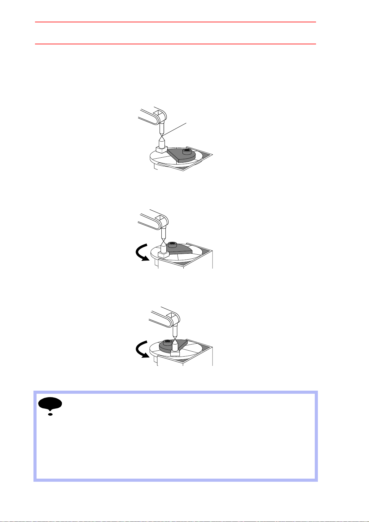
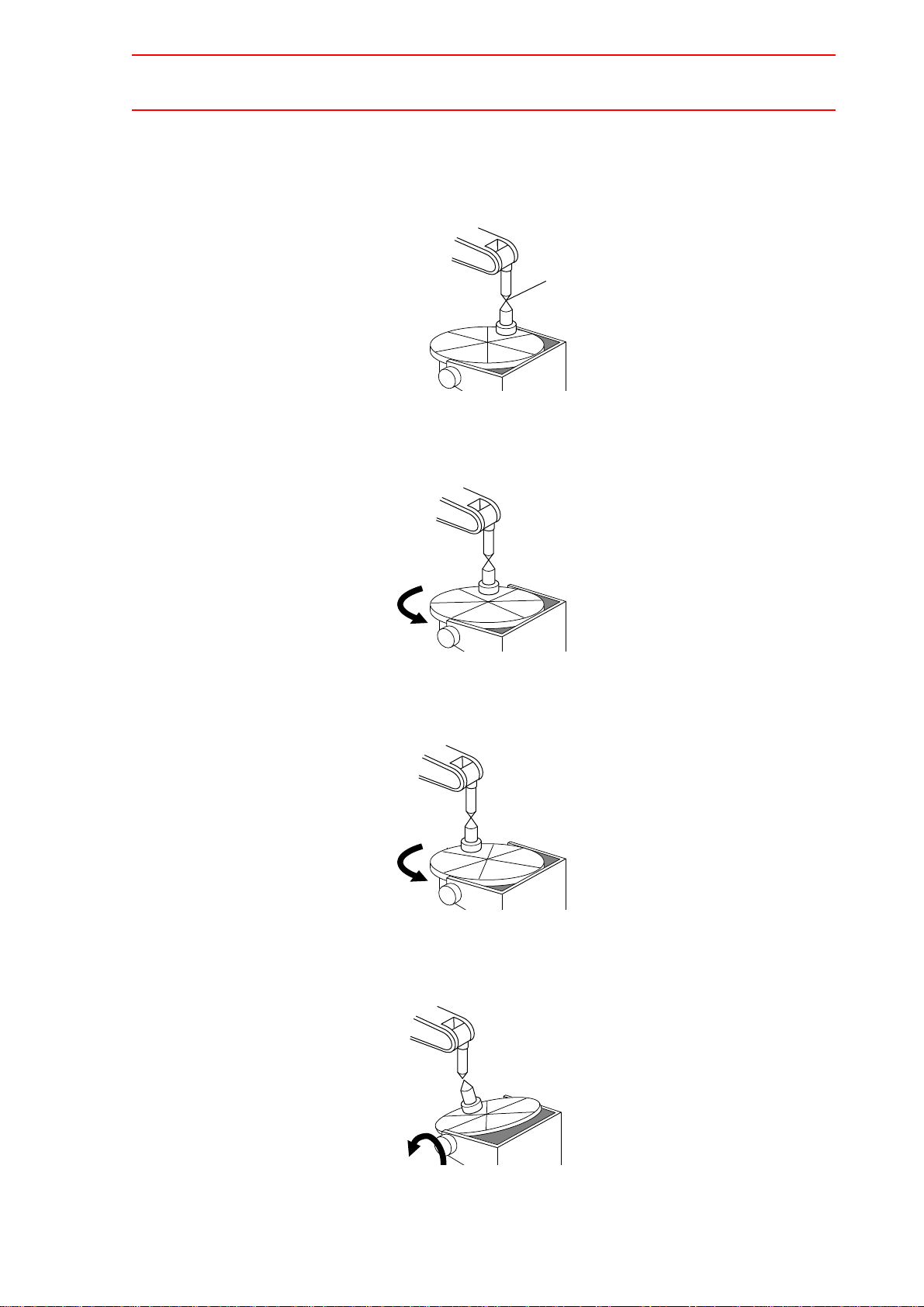
Teaching Positions for Calibration
For a station with one rotating axis
1. Determine an arbitrary point (point P) on the turntable of the station axis. Point P
should be as far as possible from the turntable rotation center. Align the TCP of the
manipulator with point P, and register it as C1.
2. Turn the station axis. The amount of turning is not limited but should be 30or more. It
does not matter if the rotational direction is positive or negative. Then, align the TCP of
the manipulator to point P, and register it as C2.
3. Turn the station axis further in the same direction as in step 2. Then, align the TCP of
the manipulator to point P, and register it as C3.
• To minimize teaching error, attach a tool with a pointed end tool on the station axis as
shown in the figure above, and use this pointed end as an arbitrary point (point P) when
teaching.
• When registering C2 and C3, the manipulator tool should keep as much as possible the
same orientation as when C1 was registered.
• The manipulator at teaching should have its L-axis at a 90 angle to the ground and its Uaxis parallel to the ground.
• Do not teach with the L-axis and U-axis fully extended or tightly contracted. Otherwise,
inaccurate calibration will result.
2-11
Page 27
2.4 System Setup
C1
Point P
C2
Turn
C3
Turn
C4
Turn
27/210
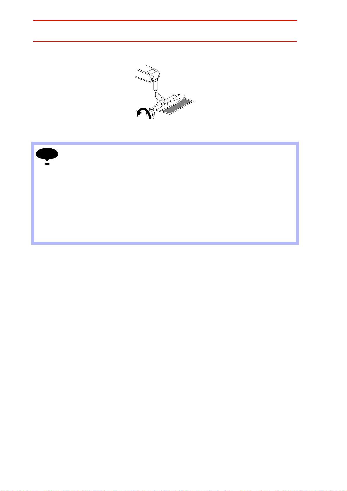
For a station with two rotating axes
1. Determine an arbitrary point (point P) on the turntable. Point P should be as far as
possible from the rotation center of the turntable. With the 1st station axis parallel to
the ground, align the TCP of the manipulator to point P, and register it as C1.
2. Turn the 2nd station axis about 30. Align the TCP of the manipulator to point P, and
register it as C2.
3. Turn the 2nd station axis again for about 30. Align the TCP of the manipulator to point
P, and register it as C3.
4. Turn the 1st station axis about 30. Align the TCP of the manipulator to point P, and
register it as C4.
2-12
Page 28
2.4 System Setup
C5
Turn
NOTE
28/210
5. Turn the 1st station axis again for about 30. Align the TCP of the manipulator to point
P, and register it as C5.
• To minimize teaching error, attach a tool with a pointed end tool on the station axis as
shown in the figure above, and use this pointed end as an arbitrary point (point P) when
teaching.
• When registering C2 to C5, the manipulator tool should keep as much as possible the
same orientation as when C1 was registered.
• The manipulator at teaching should have its L-axis at a 90 angle to the ground and its Uaxis parallel to the ground.
• Do not teach with the L-axis and U-axis fully extended or tightly contracted. Otherwise,
inaccurate calibration will result.
• For C1, C2, and C3, the position of the 1st station axis must be the same.
• The position of the 2nd station axis for C4 and C5 must be the same as that for C3.
2-13
Page 29
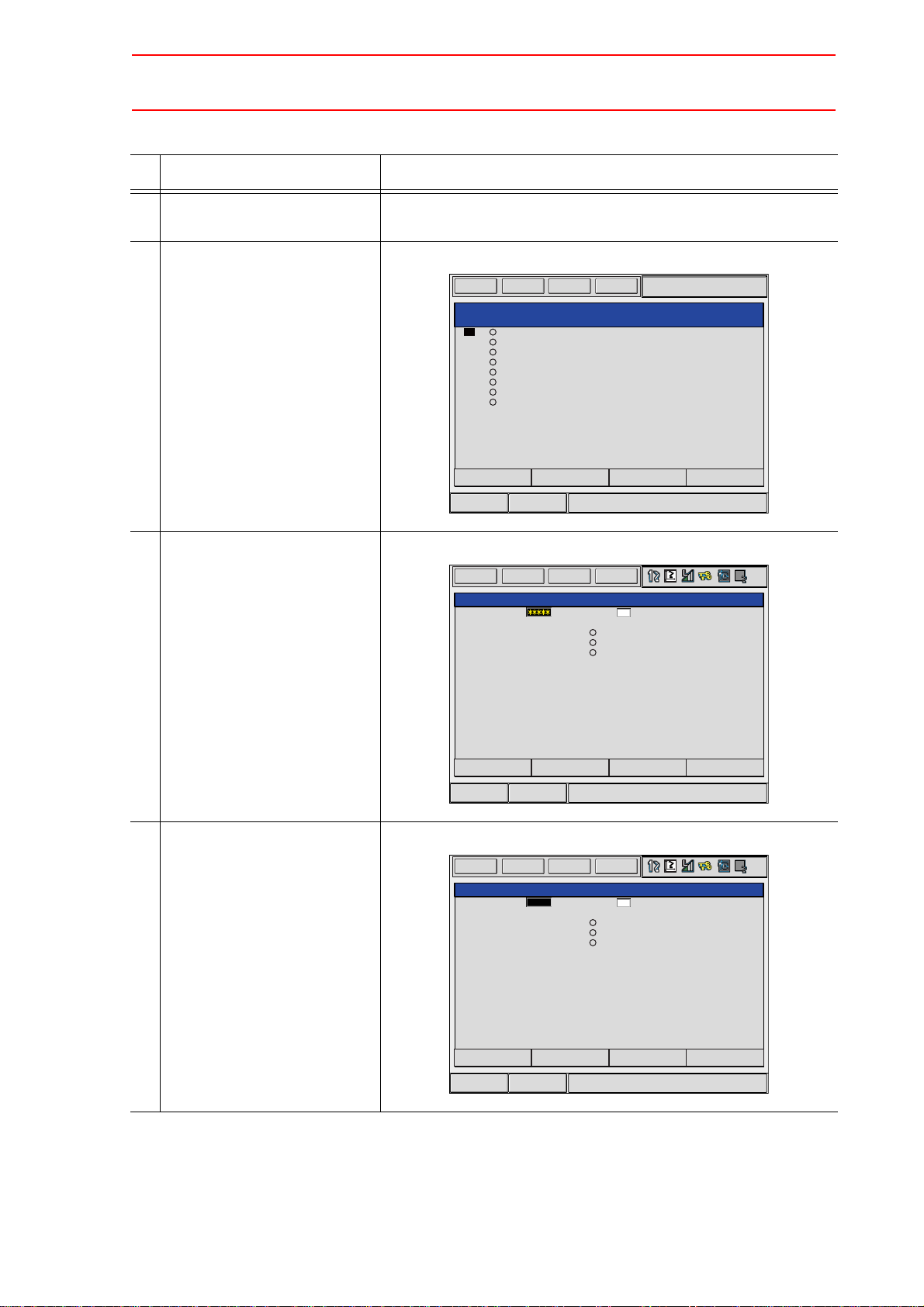
Calibration
ROBOT CALIBRATION
NO. SET ROBOT
01
02
03
04
05
06
07
08
EDIT
DISPLAY
UTILITY
DATA
Short Cut
Main Menu
ROBOT CALIBRATION
NO. :01 ROBOT
C1:
C2:
C3:
POSITION
C1
<STATUS>
CANCELCOMPLETE
EDIT
DISPLAY
UTILITY
DATA
Short Cut
Main Menu
ROBOT CALIBRAION
NO. :01 ROBOT
C1:
C2:
C3:
POSITION
C1
<STATUS>
R1+S1
CANCELCOMPLETE
EDIT
DISPLAY
UTILITY
DATA
Short Cut
Main Menu
29/210
Operation Explanation
1 Select {ROBOT} under the
main menu.
2 Select {ROBOT CALIB}. The ROBOT CALIBRATION list window appears.
2.4 System Setup
3 Select a robot calibration No. The ROBOT CALIBRATION window for teaching appears.
4 Select “ROBOT.” The selection dialog box appears.
2-14
Page 30
2.4 System Setup
ROBOT CALIBRATION
NO. :01 ROBOT
C1:
C2:
C3:
POSITION
C1
<STATUS>
R1:S
L
U
R
B
T
R1+S1
TOOL:00
CANCELCOMPLETE PAGE
EDIT
DISPLAY
UTILITY
DATA
Short Cut
Main Menu
C1:
C2:
C3:
C1
R1:S
L
U
R
B
T
R1+S1
C1
C2
C3
ROBOT CALIBRATION
NO. :01 ROBOT
POSITION
<STATUS>
TOOL:00
CANCELCOMPLETE PAGE
EDIT
DISPLAY
UTILITY
DATA
Short Cut
Main Menu
PAGE
GO BACK
C1:
C2:
C3:
C1
R1:S
L
U
R
B
T
R1+S1
12345
1025
10230
1010
521
2340
ROBOT CALIBRATION
NO. :01 ROBOT
POSITION
<STATUS>
TOOL:00
CANCELCOMPLETE PAGE
EDIT
DISPLAY
UTILITY
DATA
Short Cut
Main Menu
30/210
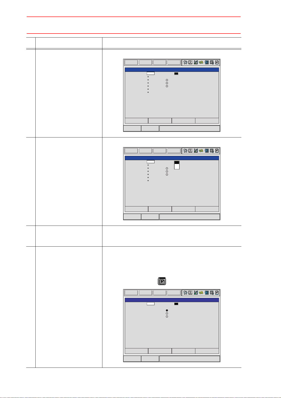
Operation Explanation
5 Select a group axis combina-
The teaching positions are displayed.
tion for calibration.
6 Select “POSITION.” The selection dialog box appears.
7 Press the axis key to move the
manipulator to the desired
position.
8 Press [MODIFY] and
[ENTER].
The positions for calibration are registered.
Repeat Operations 7 and 8 to teach set positions C1 to C3.
On the window, “” indicates that the teaching is completed while
“” indicates that the teaching is not completed.
The calibration positions appear according to the selected group
axis. Press the page key to change the window.
2-15
Page 31

2.4 System Setup
01
02
03
04
05
06
07
08
ROBOT CALIBRATION
NO. SET ROBOT
EDIT
DISPLAY
UTILITY
DATA
Short Cut
Main Menu
31/210
Operation Explanation
9 Select “COMPLETE.” The robots are calibrated. When the calibration is completed, the
ROBOT CALIBRATION list window reappears.
2-16
Page 32

2.5 JOB CONTENT Window
JOB CONTENT
JOB NAME: TEST
CONTROL GROUP: R1+S1:S1
STEP NO.: 002
TOOL: 00
0001
0002
0003
SMOVL V=138
+MOVJ
MOVL V=138
+MOVJ VJ=3.12
END
SMOVL V=138
+MOVJ
Instructions
Synchronized/Single
Group axis being handled
Coordinated interpolation/
Independent interpolation
EDIT
DISPLAY
UTILITY
JOB
Short Cut
Main Menu
32/210
2.5 JOB CONTENT Window
An example of the contents of a coordinated job is shown below.
Instructions
For a coordinated job, the move instruction is displayed in two lines: The first line is the
instruction to the slave side; the second line is the instruction to the master side.
SMOVL V=138 Slave, a manipulator
+MOVJ Master, a station
Synchronized/Single
Synchronized/single are the types of movement available for the manipulator during axis
operation. This mark appears when synchronized movement is selected.
Switch between movements by pressing [SYNCRO/SINGLE].
Group axis being handled
Displays the group axis being handled.
Pressing [ROBOT] selects the manipulator.
Pressing [EX. AXIS] selects the station.
Coordinated interpolation/Individual interpolation
Switch between coordinated interpolation and individual interpolation by pressing [SMOV].
2-17
Page 33

2.6 Synchronized/Single
UTILITY
UTILITY
When "Single" is selected, nothing appears here.
33/210
2.6 Synchronized/Single
There are two ways to handle axes when teaching: “Synchronized” and “Single.”
Switch between movements by pressing [SYNCRO/SINGLE].
2.6.1 Synchronized
If the axes are handled in the “Synchronized” mode, the slave (manipulator) follows the master (station) when the master moves. This feature is used to keep the position of the manipulator relative to the station.
However, the master does not move when the slave is moved.
• A master axis is moved:
2-18
Page 34

2.6 Synchronized/Single
NOTE
34/210
2.6.2 Single
If an axis is handled in “Single” mode, the manipulator or the station whose axis has been
handled, moves.
This feature is used where a manipulator and a station each execute an individual job.
• A slave axis is moved:
• A master axis is moved:
• The selected mode, Synchronized or Single, is maintained until the next selection is
made.
• When an edit job is changed, “Single” is automatically selected.
2-19
Page 35

2.7 Selecting Axis to be Handled
35/210
2.7 Se le ct ing Ax is to be Ha nd led
In a coordinated system with multiple numbers of group axes, select a group axis to be handled in the following manner.
2.7.1 When There is an Edit Job
When the edit job is displayed, the group axes registered in the displayed job is the one to be
handled.
Pressing [ROBOT] selects a manipulator for axis handling.
Pressing [EX. AXIS] selects a station for axis handling.
2.7.2 When There is No Edit Job
When there is no edit job, move a manipulator in the following manner.
1. Press [SHIFT]+[ROBOT] to change the manipulator for axis handling. The LED of
[ROBOT] flashes.
Press [SHIFT]+[EX. AXIS] to change the station for axis handling. The LED of [EX.
AXIS] flashes.
2. Select the group axes to be moved, and then move it by pressing the axis key.
3. Press [ROBOT] or [EX. AXIS] to return to the original window.
2-20
Page 36

2.8 Registering Job
NEW JOB CREATE
JOB NAME
COMM.
GROUP SET R1
CANCELEXECUTE
EDIT
DISPLAY
UTILITY
JOB
Short Cut
Main Menu
36/210
2.8 Registering Job
Operation Explanation
1 Select {JOB} under the main
menu.
2 Select {CREATE NEW JOB}. The NEW JOB CREATE window appears.
3 Enter a job name. Select “JOB NAME,” and then enter a job name by entering the
characters. Refer to “1.2.7 Character Input” of the Operator’s
Manual.
4 Press [ENTER].
5 Select “GROUP SET.”
6 Select a group combination.
7 Select “EXECUTE.” The job name is registered in the memory of NX100, and the JOB
CONTENT window appears.
2-21
Page 37

2.9 Registering Move Instruction (S)MOV+MOVJ
UTILITY
UTILITY
UTILITY
When "Single" is selected, nothing appears here.
37/210
2.9 Registering Move Instruction (S)MOV+MOVJ
Register a move instruction in the following manner.
2.9.1 Operating Master Side (Station)
Operation Explanation
1 Call the JOB CONTENT win-
dow in teach mode.
2 Press [EX. AXIS]. The master side (station) is selected for axis handling.
3 Select either “synchronized” or
“single.”
4 Press the axis key to move to
the desired position.
Press [SYNCRO/SINGLE] to select either “synchronized” or “single.”
When “synchronized” is selected, the mark in the window below
appears.
When the slave side is supposed to follow the master side
motion, select “synchronized.”
2-22
Page 38

2.9 Registering Move Instruction (S)MOV+MOVJ
Short CutMain Menu
SMOVL V=138
+MOVJ
SMOVC V=138
+MOVJ
Short CutMain Menu
0003 SMOVC V=138
+MOVJ
NOTE
38/210
2.9.2 Operating Slave Side (Manipulator)
Operation Explanation
1 Press [EX. AXIS]. The slave side (manipulator) is selected for axis handling.
2 Press the axis key to move to
the desired position.
3 Select either a coordinated
Press [SMOV] to select either interpolation.
interpolation or an independent interpolation.
4 Select an interpolation type. Press [MOTION TYPE] to select an interpolation type.
5 Confirm the speed.
6 Press [ENTER]. The registration is completed as follows.
• When joint interpolation is set for the slave side (manipulator), teaching cannot be done
during a coordinated operation.
• When “JOINT” is selected, the interpolation type will not change to a coordinated interpolation, even if [SMOV] is pressed.
• When “JOINT” is selected during coordinated interpolation, a coordinated move instruction such as “SMOVL” in the input buffer line changes to “MOVJ,” and the interpolation
type becomes individual interpolation.
Parameter Contents and Set Value
S2C164 Specifies whether the speed inputting for move instructions of the
master side robot in a coordinated job is permitted or not.
<Example> 0: Not Provided 1: Provided
SMOVL
+MOVJ Master
V=100 SMOVL V=100
+MOVJ VJ=10.00
side
Speed specification not
provided
Master
side
Speed specification
provided
Initial
Value
0
2-23
Page 39

2.10 Registering Reference Point Instruction (SREFP)
0003
0004
0005
0006
0007
SMOVL V=558
+MOVJ
CALL JOB: TEST
SMOVL V=138
+MOVJ
Immediately before
the line where the
reference point
instruction is to
be registered
SREFP 1
SREFP 2
Ref-point_no.=
SREFP
0003
0004
0005
0006
0007
0008
SMOVL V=558
+MOVJ
CALL JOB:TEST
SREFP 1
SMOVL V=138
+MOVJ
The reference point
instruction is registered.
39/210
2.10 Registering Reference Point Instruction (SREFP)
Register a reference point instruction (SPEFP) for a coordinated interpolation in the following
manner.
Operation Explanation
1 Select {JOB} under the main
menu.
2 Select {JOB}.
3 Move the cursor. Move the cursor to the line immediately before the line where the
reference point instruction is to be registered.
4 Grasp the Enable switch.
5 Press the axis key. Turn ON the servo power with the Enable switch. Move the
manipulator to the position which will be a reference point.
6 Select the coordinated interpo-
Press [SMOV] to select a coordinated operation.
lation.
7 Press [REF PNT]. The reference point instruction appears in the input buffer line.
8 Change the reference point
number.
Move the cursor to the reference point number,
[SHIFT] +
the cursor key
to change the reference point number.
and press
If you use the Numeric keys to change the reference point number, press [SELECT] when the cursor is on the reference point
number. Input the number and press [ENTER].
9 Press [INSERT]. The [INSERT] key lamp lights up.
When registering immediately before the END instruction, pressing [INSERT] is not needed.
10 Press [ENTER]. The REFP instruction is registered.
2-24
Page 40

3.1 Outline
To NX100
Coordinated operation
Individual operation
Slave
MOVL
+MOVL
SMOVL
+MOVL
Master
40/210
3 Jigless System
3.1 Outline
A jigless system is a system that welds by coordinating two manipulators; one holding the
workpiece while the other holds the torch.
To coordinate the movements of the two manipulators, a coordinated job is needed.
In a coordinated job, there is a coordinated operation where two manipulators, master and
slave, perform a reciprocal movement, and an individual operation where each of the two
manipulators performs an independent movement.
A move instruction in coordinated jobs displays two lines. The first line is for the slave side
(torch); the second line is for the master side (workpiece).
3-1
Page 41

3.2 Specific Keys
1
TIMER
0
REFP
8
ARCON
41/210
3.2 Specific Keys
The specific keys for the jigless system are allocated to the number keys as shown in the figure below.
Registers a timer instruction “TIMER” in a job.
Registers a reference point “REFP” in a job, or modifies the registered reference point.
[REFP] + [FWD]
Moves the manipulator to the registered reference point.
Registers a welding start instruction “ARCON” in a job.
3-2
Page 42

3.2 Specific Keys
5
ARCOFF
GAS
INTER
LOCK
+
5
ARCOFF
GAS
9
FEED
6
RETRACT
7
SYNCRO
SINGLE
4
SMOV
SUPPLE-
MENT
NO TE
42/210
Registers a welding end instruction “ARCOF” in a job.
(These keys are for future use and disabled in the current version.)
Used for the gas flow control.
Pressing [INTERLOCK] + [GAS ARCOFF] once opens the gas valve for 20
seconds, and then the valve automatically closes.
Pressing [INTERLOCK] + [GAS ARCOFF] again within the 20 seconds,
the gas valve can be manually closed.
Used for wire inching. Press [FEED] to feed the wire, and press
[RETRACT] to retract the wire.
While these keys are pressed, the wire feed motor operates.
When the following are pressed simultaneously, wire inching is performed
in the high speed mode.
[HIGH SPEED] + [FEED]
[HIGH SPEED] + [RETRACT]
Changes the type of movement for the manipulator when teaching a coordinated job. Each time this key is pressed, the movement type changes.
SYNCRO: The mark for “synchronized” appears in the status display area.
When the master side is moved, the slave side will follow the
movement of the master.
SINGLE: Only the selected group axis moves.
Selects either a coordinated or an individual interpolation when teaching a
coordinated job. Each time this key is pressed, the operation type
changes.
Coordinated: All the move instructions that are registered in this mode
become coordinated instructions.
Individual: The master-slave relationship is cancelled. Each manipulator
and station moves independently.
Wire retraction, high-speed inching, or high-speed retraction cannot be performed depending on the Power Source.
[7:SYNCRO/SINGLE] and [4: SMOV] keys are available only when "FUNCTION" setting
for each key is specified to "MAKER" in both KEY ALLOCATION(EACH) screen and KEY
ALLOCATION(SIM) screen.
3-3
Page 43

3.3 Opening and Closing Handling Tool
NOTE
INTER
LOCK
+
2
TOOLON
INTER
LOCK
+
.
TOOLOF
INTER
LOCK
+
3
TOOLON
JOB
INTER
LOCK
+
-
TOOLOF
JOB
43/210
3.3 Opening and Closing Handling Tool
This section explains how to open and close a handling tool by teaching. It is unrelated to the
content of the job being taught. To close and open a handling tool by pressing the specific
keys, the general output signals #17 to 20 are used.
The general output signal No. can be changed by the parameter A1P.
A1P026 Tool1 ON general output No. (Initial value: 17)
A1P027 Tool1 OFF general output No. (Initial value: 18)
A1P028 Tool 2 ON general output No. (Initial value: 19)
A1P029 Tool 2 OFF general output No. (Initial value: 20)
Sends an open instruction to Tool 1.
Only while the keys are pressed, general output signal #17 is ON.
Sends a close instruction to Tool 1.
Only while the keys are pressed, general output signal #18 is ON.
Sends an open instruction to Tool 2.
Only while the keys are pressed, general output signal #19 is ON.
Sends a close instruction to Tool 2.
Only while the keys are pressed, general output signal #20 is ON.
3-4
Page 44

3.4 Example of Teaching Job
Stand-by
Starting
During an operation
The torch moves to the cleaner. The workpiece is uncloaded.
Ending
Separate from the workpiece
Step Instruction
001 MOVJ VJ=50.00
+MOVJ
002 SMOVL V=200
+MOVL
SWVON WEV#(1)
ARCON ASF#(1)
003 SMOVL V=200
+MOVL
004 SMOVL V=200
+MOVL
ARCOF AEF#(1)
SWVOF
005 MOVJ VJ=50.00
+MOVJ
006 MOVJ VJ=50.00
+MOVJ
Coordinated operation
44/210
3.4 Example of Teaching Job
3-5
Page 45

3.5 System Setup
EDIT
DISPLAY UTILITY
DATA
Short Cut
Main Menu
GROUP COMBINATION
GROUP AXIS MASTER
R1
R2
ADD GROUP
MODIFY GROUP
DELETE GROUP
EDIT
DISPLAY UTILITYDATA
GROUP COMBINATION
GROUP AXIS MASTER
GROUP COMBI SET
NO.1 CONTROL GROUP
NO.2 CONTROL GROUP
MASTER
CANCEL
EXECUTE
EDIT
DISPLAY UTILITY
DATA
Short Cut
Main Menu
45/210
3.5.1 Registering Group Combination
Register a combination of two manipulators.
Operation Explanation
1 Select {SETUP} under the
main menu.
2 Select {GRP COMBINATION}. The GROUP COMBINATION window appears.
3.5 System Setup
3 Press [SELECT]. The selection dialog box appears.
4 Select “ADD GROUP.” The GROUP COMBI SET window appears.
3-6
Page 46

3.5 System Setup
GROUP COMBI SET
NO.1 CONTROL GROUP
NO.2 CONTROL GROUP
MASTER
R1: ROBOT1
R2: ROBOT2
CANCELEXECUTE
EDIT
DISPLAY
UTILITY
DATA
Short Cut
Main Menu
R1
R2
R1
GROUP COMBI SET
NO.1 CONTROL GROUP
NO.2 CONTROL GROUP
MASTER
CANCELEXECUTE
EDIT
DISPLAY
UTILITY
DATA
Short Cut
Main Menu
GROUP COMBINATION
GROUP AXIS MASTER
R1
S1
R1+R2 R2
EDIT
DISPLAY
UTILITY
DATA
Short Cut
Main Menu
46/210
Operation Explanation
5 Press [SELECT]. The selection dialog box appears.
6 Select a group axis to be set. Set R2: ROBOT2 as “MASTER.”
7 Select “EXECUTE.” The GROUP COMBINATION window reappears.
3-7
Page 47

3.5 System Setup
Tool for calibration
TOOL
TOOL NO. : 0 / 1
NAME
X
Y
Z
W
Xg
Yg
Zg
0.000
0.000
0.000
STANDARD TOOL
mm
mm
mm
0.000 kg
0.000
0.000
0.000
mm
mm
mm
Rx
Ry
Rz
Ix
Iy
Iz
0.000
0.000
deg.
deg.
deg.
0.000
0.000
0.000
kg m2
0.000
kg m2
kg m2
EDIT
DISPLAY
UTILITY
DATA
Short Cut
Main Menu
47/210
3.5.2 Calibration between Manipulators
For a coordinated operation between manipulators, prior registration of the settings for mutual
positioning is required. This relationship is set by calibration between manipulators.
Calibration Tool Setting
Operation Explanation
1 Mount a tool for calibration on
Use a tool whose exact dimensions are known.
the manipulator.
2 Select {ROBOT} under the
main menu.
3 Select {TOOL}. The TOOL window appears.
4 Enter the tool dimensions.
5 Press [ENTER].
3-8
Page 48

3.5 System Setup
C1
C2
C3
NOTE
48/210
Teaching Position for Calibration
Calibrate the control point for two manipulators at three arbitrary points (C1 to C3) in the
space between the manipulators.
1. Move a manipulator to an arbitrary position. Align the tool center point of the other
manipulator or to the tool center point of the first manipulator by handling the axis.
Register it as C1.
2. Register C2 and C3 in the same manner as C1.
• When registering C2 and C3, the manipulator tool should keep as much as possible the
same orientation as when C1 was registered.
• The standard distance between C-1and C-2, C2 and C3, and C3 and C1 should be 1 m or
more.
• Teach C1, C2, and C3 so that a triangle, not a straight line, is formed.
• Do not teach with the LU axis fully extended or tightly contracted. Otherwise, inaccurate
calibration will result.
3-9
Page 49

Calibration
ROBOT CALIBRATION
NO. SET ROBOT
01
02
03
04
05
06
07
08
EDIT
DISPLAY
UTILITY
DATA
Short Cut
Main Menu
ROBOT CALIBRATION
NO. :01 ROBOT
C1:
C2:
C3:
POSITION
C1
<STATUS>
CANCELCOMPLETE
EDIT
DISPLAY
UTILITY
DATA
Short Cut
Main Menu
ROBOT CALIBRAION
NO. :01 ROBOT
C1:
C2:
C3:
POSITION
C1
<STATUS>
R1+R2
CANCELCOMPLETE
EDIT
DISPLAY
UTILITY
DATA
Short Cut
Main Menu
49/210
Operation Explanation
1 Select {ROBOT} under the
main menu.
2 Select {ROBOT CALIB}. The ROBOT CALIBRATION list window appears.
3.5 System Setup
3 Select a robot calibration No. The ROBOT CALIBRATION window for teaching appears.
4 Select “ROBOT.” The selection dialog box appears. Select a control group for cali-
bration.
3-10
Page 50

3.5 System Setup
ROBOT CALIBRATION
NO. :01 ROBOT
C1:
C2:
C3:
POSITION
C1
<STATUS>
R1:S
L
U
R
B
T
R1+R2
TOOL:00
CANCELCOMPLETE PAGE
EDIT
DISPLAY
UTILITY
DATA
Short Cut
Main Menu
C1:
C2:
C3:
C1
R1:S
L
U
R
B
T
R1+R2
C1
C2
C3
ROBOT CALIBRATION
NO. :01 ROBOT
POSITION
<STATUS>
TOOL:00
CANCELCOMPLETE PAGE
EDIT
DISPLAY
UTILITY
DATA
Short Cut
Main Menu
PAGE
GO BACK
C1:
C2:
C3:
C1
R1:S
L
U
R
B
T
R1+R2
12345
1025
10230
1010
521
2340
ROBOT CALIBRATION
NO. :01 ROBOT
POSITION
<STATUS>
TOOL:00
CANCELCOMPLETE PAGE
EDIT
DISPLAY
UTILITY
DATA
Short Cut
Main Menu
50/210
Operation Explanation
5 Select a group axis combina-
The teaching positions are displayed.
tion for calibration.
6 Select “POSITION.” The selection dialog box appears. Select a position to be taught.
7 Press the axis key to move the
manipulator to the desired
position.
8 Press [MODIFY] and
[ENTER].
The positions for calibration are registered.
Repeat Operations 7 and 8 to teach set positions C1 to C3.
On the window, “” indicates that the teaching is completed while
“” indicates that the teaching is not completed.
The calibration positions appear according to the selected group
axis. Press the page key to change the window.
3-11
Page 51

3.5 System Setup
01
02
03
04
05
06
07
08
ROBOT CALIBRATION
NO. SET ROBOT
EDIT
DISPLAY
UTILITY
DATA
Short Cut
Main Menu
R1+R2
51/210
Operation Explanation
9 Select “COMPLETE.” The robots are calibrated. When the calibration is completed, the
ROBOT CALIBRATION list window reappears.
3-12
Page 52

3.6 Job Content Display
JOB CONTENT
JOB NAME: TEST
CONTROL GROUP: R1+R2:R1
STEP NO.: 001
TOOL: 00+01
0000
0001
0002
0003
NOP
SMOVL V=138
+MOVL
MOVL V=138
+MOVL V=138
END
MOVL V=138
+MOVL V=138
Instructions
Synchronized/Single
Group axis being handled
Coordinated interpolation/
Independent interpolation
EDIT
DISPLAY
UTILITY
JOB
Short Cut
Main Menu
52/210
3.6 Job Content Display
The contents of a coordinated job are displayed as shown below.
Instructions
For coordinated jobs, the move instruction, the weaving instruction, the shift instruction, and
others are displayed in two lines. The first line is the instruction to the slave side; the second line is the instruction to the master side.
SMOVL V=138 Slave, the manipulator holding a torch
+MOVL Master, the manipulator holding a workpiece
Synchronized/Single
Synchronized/single are the types of movement available for the manipulator during axis
operation. This mark appears when synchronized movement is selected.
Switch between movements by pressing [SYNCRO/SINGLE].
Group axis being handled
Displays the group axis being handled.
Press [ROBOT] to change the group axis to be handled.
Coordinated operation/Individual operation
Switch between coordinated operation and individual operation by pressing [SMOV].
3-13
Page 53

3.7 Synchronized/Single
UTILITY
UTILITY
When "Single" is selected, nothing appears here.
53/210
3.7 Synchronized/Single
There are two ways to handle axes when teaching: “Synchronized” and “Single”.
Switch between movements by pressing [SYNCRO/SINGLE].
3.7.1 Synchronized
If the axes are handled in the “Synchronized” mode, the slave (torch) follows the master
(workpiece) when the master moves. This feature is used to keep the position of the manipulator relative to the other manipulator.
However, the master does not move when the slave is moved.
3-14
Page 54

3.7 Synchronized/Single
Only the manipulator whose
axis is handled moves.
NOTE
54/210
3.7.2 Single
If an axis is handled in “Single” mode, only the manipulator whose axis is being handled
moves.
This feature is used where each of the two manipulators executes an individual job.
• The selected mode, Synchronized or Single, is maintained until the next selection is
made.
• When an edit job is changed, “Single” is automatically selected.
3-15
Page 55

3.8 Selecting Axis to be Handled
UTILITY
UTILITY
2
55/210
3.8 Se le ct ing Ax is to be Ha nd led
This section explains the methods to select a manipulator to be handled in teach mode.
3.8.1 When There is an Edit Job
Each time [ROBOT] is pressed, a manipulator to be handled changes.
3.8.2 When There is No Edit Job
When there is no edit job, move the manipulator in the following manner.
1. Press [SHIFT]+[ROBOT] to change the manipulator to be handled. The LED of
[ROBOT] flashes.
2. Select the group axes to be moved, and then move it by pressing the axis key.
3. Press [ROBOT] to return to the original display.
3-16
Page 56

3.9 Registering Job
NEW JOB CREATE
JOB NAME
COMM.
GROUP SET R1
CANCELEXECUTE
EDIT
DISPLAY
UTILITY
JOB
Short Cut
Main Menu
56/210
3.9 Registering Job
Operation Explanation
1 Select {JOB} under the main
menu.
2 Select {CREATE NEW JOB}. The NEW JOB CREATE window appears.
3 Enter a job name. Select “JOB NAME,” and then enter a job name by entering the
characters. Refer to “1.2.7 Character Input” of the Operator’s
Manual.
4 Press [ENTER].
5 Select “GROUP SET.”
6 Select a group combination.
7 Select “EXECUTE.” The job name is registered in the memory of NX100, and the JOB
CONTENT window appears.
3-17
Page 57

3.10 Registering Move Instruction (S)MOV+MOV
UTILITY
UTILITY
UTILITY
When "Single" is selected, nothing appears here.
SMOVL V=138
+MOVJ
Short CutMain Menu
57/210
3.10 Registering Move Instruction (S)MOV+MOV
Register a move instruction in the following manner.
3.10.1 Operating Master Side (Workpiece)
Operation Explanation
1 Call the JOB CONTENT win-
dow in teach mode.
2 Press [EX. AXIS]. The master side (station) is selected for axis handling.
3 Select either “synchronized” or
“single.”
4 Press the axis key to move to
the desired position.
5 Select an interpolation type. Press [MOTION TYPE] to select an interpolation type.
Press [SYNCRO/SINGLE] to select either “synchronized” or “single.”
When “synchronized” is selected, the mark in the window below
appears.
When the slave side is supposed to follow the master side
motion, select “synchronized.”
3-18
Page 58

3.10 Registering Move Instruction (S)MOV+MOV
2
Short CutMain Menu
SMOVL V=138
+MOVL
SMOVC V=138
+MOVL
Short CutMain Menu
0003 SMOVC V=138
+MOVL
NOTE
58/210
3.10.2 Operating Slave Side (Torch)
Operation Explanation
1 Press [EX. AXIS]. The slave side (manipulator) is selected for axis handling.
2 Press the axis key to move to
the desired position.
3 Select either a coordinated
Press [SMOV] to select either interpolation.
interpolation or an independent interpolation.
4 Select an interpolation type. Press [MOTION TYPE] to select an interpolation type.
5 Confirm the speed.
6 Press [ENTER]. The registration is completed as follows.
• When joint motion is set for the slave side (torch), teaching cannot be done during a coordinated operation.
• When “JOINT” is selected, the interpolation type will not change to a coordinated operation, even if [SMOV] is pressed.
• When “JOINT” is selected during coordinated interpolation, a coordinated move instruction such as “SMOVL” in the input buffer line changes to “MOVJ”, and the interpolation
type becomes individual interpolation.
3-19
Page 59

3.11 Registering Reference Point Instruction (SREFP)
0003
0004
0005
0006
0007
SMOVL V=558
+MOVL
CALL JOB: TEST
SMOVL V=138
+MOVL
Immediately before
the line where the
reference point
instruction is to
be registered
SREFP 1
SREFP 2
Ref-point_no.=
SREFP
0003
0004
0005
0006
0007
0008
SMOVL V=558
+MOVL
CALL JOB:TEST
SREFP 1
SMOVL V=138
+MOVL
The reference
point instruction
is registered.
59/210
3.11 Registering Reference Point Instruction (SREFP)
Register a reference point instruction (SPEFP) for a coordinated operation in the following
manner.
Operation Explanation
1 Select {JOB} under the main
menu.
2 Select {JOB}.
3 Move the cursor. Move the cursor to the line immediately before the line where the
reference point instruction is to be registered.
4 Grasp the Enable switch.
5 Press the axis key. Turn ON the servo power with the Enable switch. Move the
manipulator to the position which will be a reference point.
6 Select the coordinated interpo-
Press [SMOV] to select either interpolation.
lation.
7 Press [REF PNT]. The reference point instruction appears in the input buffer line.
8 Change the reference point
number.
Move the cursor to the reference point number,
[SHIFT] +
the cursor key
to change the reference point number.
and press
If you use the Numeric keys to change the reference point number, press [SELECT] when the cursor is on the reference point
number. Enter the number and press [ENTER].
9 Press [INSERT]. The [INSERT] key lamp lights up.
When registering immediately before the END instruction, pressing [INSERT] is not needed.
10 Press [ENTER]. The REFP instruction is registered.
3-20
Page 60

3.12 Registering Handling Instructions
2
TOOLON
.
TOOLOF
3
TOOLON
JOB
-
TOOLOF
JOB
60/210
3.12 Registering Handling Instructions
To register handling instructions, the specific keys [TOOL1 ON], [TOOL1 OFF], [TOOL2 ON],
and [TOOL2 OFF] are used. When these keys are pressed, the instructions shown in the following table are registered. The general output signals #17 to 20 and the general input signals #17 to 20 are used for handling.
To o l 1
To o l 2
General Output
Tool
Open #17 #17 CALL JOB : H1OPEN
Close #18 #18 CALL JOB : H1CLOSE
Open #19 #19 CALL JOB : H2OPEN
Close #20 #20 CALL JOB : H2CLOSE
Specific
key
Signal No.
(Instruction
Output)
General Input
Signal No.
(Confirmation
Input)
Instruction to be Registered
Also by registering a CALL instruction from the instruction list dialog, the instructions in the
above table can be registered.
The H1OPEN, H1CLOSE, H2OPEN, and H2CLOSE are reserved jobs. The job contents
must have been registered beforehand. Register a handling instruction according to the application.
An example of H1OPEN registration is shown.
<Example>
The OPEN and CLOSE instructions are of pulse outputs.
After the OPEN or CLOSE instruction, the manipulator waits for a confirmation of the movement.
NOP
PULSE OT#1
WAIT IN#17
H1OPEN instruction 0.3 second pulse output
Waits for confirmation of H1OPEN
RET
3-21
Page 61

3.13 Other Convenient Features
Manipulator R1
(Master side)
Manipulator R2
(Slave side)
X-axis
Z-axis
Y-axis
Tool center
point of R2
Tool coordinates
61/210
3.13 Other Convenient Features
In a jigless system, the control point of slave side manipulator can be set as a reference point
so that the master side manipulator can be moved.
3.13.1 Example of Movement
3-22
Page 62

3.13 Other Convenient Features
EDIT
DISPLAY UTILITY
DATA
Short Cut
Main Menu
Turn on servo power
SWITCH TO TOOL COORD
ROBOT: R1
CONTROL POINT:
R1 TOOL 00
R2 TOOL 01
62/210
3.13.2 Operation Method
Operation Explanation
1 Select the tool coordinate sys-
Press [COORD] and select a tool coordinate system.
tem.
2 Press [SHIFT] + [COORD]. The switch to tool coordination display is shown.
3 Select a operation tool coordi-
nate.
Select a manipulator with whose tool center point the manipulator
is moved. At turning ON the power supply, the tool center point of
the currently selected manipulator is shown.
3-23
Page 63

3.13 Other Convenient Features
T-
Z-
T+
Z+
B+
Y+
R+
X+
B-
Y-
R-
X-
Tool coordinates
on slave side
X+
S+
Y+
L+
Tool center point of the slave side
X-axis
Y-axis
Parallel movement
63/210
3.13.3 Manipulator Movement
The operation by the axis keys is the same as that on normal tool coordinate system.
Axis
Name
Basic axes
Wrist
axes
Axis Key Movement
Moves in parallel to X, Y, and Z-axis of tool coordinates
of the selected manipulator.
With the tool center point of the selected manipulator as
a reference point, TCP fixed operation is executed.
Basic axes
3-24
Page 64

3.13 Other Convenient Features
Slave side tool center point
TCP fixed operation
The slave moves
The master moves
The slave does not move.
The master moves.
64/210
Wrist axes
Executing a TCP fixed operation by wrist axes, can change only the wrist orientation without
changing its position, with the tool center point of the slave side manipulator as a reference
point.
Synchronized/Single
When “synchronized” is selected: The master moves with the tool center point of the slave as a
reference point.
The slave follows the master.
.
When “single” is selected: The master moves with the tool center point of the slave as a reference
point.
The slave remains stationary.
3-25
Page 65

4.1 Outline
Station
S1
Subtask 1
R1+S1
Subtask 2
R2+S1
Start
Start
Master task
such as calculation, I/O control
65/210
4 Twin Synchronous System
4.1 Outline
The twin synchronous system is a system where two manipulators operate in coordination for
one station.
In this system, two coordinated jobs are done at the same time.
A concurrent job or a robot job without control groups starts these two jobs and implements
I/O control. The master task job uses the independent control function to start the robot jobs
of subtasks 1 and 2.
Two robot jobs can be created by the following two methods.
• A coordinated job for one manipulator and the station (R1+S1)
• A coordinated job for the other manipulator and the station (R2+S1)
4-1
Page 66

4.1 Outline
Teaching
Mirror shift
Teaching
(Leader)
Teaching
(Follower)
HOLDSTART
PLAY
TEACH
REMOTE
!?
HOLDSTART
PLAY
TEACH
REMOTE
!?
66/210
Method 1: Copy one subtask job to create another subtask job.
This method is useful when two movement paths are symmetrical. Use the mirror shift function to convert a job path and copy it. The same teaching operation does not have to be
repeated.
Method 2: Perform teaching for each manipulator.
Where there are not many similarities in the paths and movements of the two manipulators,
create jobs in Method 2.
4-2
Page 67

4.2 Function Keys
89
56
13
0-
REFP
CUR/VOL
RETRACT
FEED
CUR/VOL
ARCON
ARCOFF
TIMER
GAS
7
SYNCRO
SINGLE
4
SMOV
2
.
1
TIMER
0
REFP
67/210
4.2 Function Keys
The function keys for the twin synchronous system are assigned to the Numeric keys as
shown in the figures below.
4.2.1 Arc Welding Application
Registers a timer instruction “TIMER” in a job.
Registers a reference point “REFP” in a job, or modifies the registered reference point.
[REFP] + [FWD]
Moves the manipulator to the registered reference point.
4-3
Page 68

4.2 Function Keys
8
ARCON
5
ARCOFF
GAS
INTER
LOCK
+
5
ARCOFF
GAS
9
FEED
6
RETRACT
3
CUR/VOL
-
CUR/VOL
7
SYNCRO
SINGLE
4
SMOV
SUPPLE-
MENT
NO TE
68/210
Registers a welding start instruction “ARCON.”
Registers a welding end instruction “ARCOF.”
(These keys are for future use and disabled in the current version.)
Used for the gas flow control.
Pressing [INTERLOCK] + [GAS ARCOFF] once opens the gas valve for 20
seconds, and then the valve automatically closes.
Pressing [INTERLOCK] + [GAS ARCOFF] again within the 20 seconds,
the gas valve can be manually closed.
Used for wire inching. Press [FEED] to feed the wire, and press
[RETRACT] to retract the wire.
While these keys are pressed, the wire feed motor operates.
When the following are pressed simultaneously, wire inching is performed
in the high speed mode.
[HIGH SPEED] + [FEED]
[HIGH SPEED] + [RETRACT]
Modifies the welding current/voltage while welding during the play mode.
Press [3/CUR/VOL] to increase the current/voltage value, and press
[/CUR/VOL] to decrease the current/voltage value.
(Refer to “11.6 Changing Welding Conditions During Playback” in the
Operator’s Manual.)
Changes the type of movement for the manipulator when teaching a coordinated job. Each time this key is pressed, the movement type changes.
SYNCRO: The mark for “synchronized” appears in the status display area.
When the master side is moved, the slave side will follow the
movement of the master.
SINGLE: Only the selected group axis moves.
Selects either a coordinated or an individual interpolation when teaching a
coordinated job. Each time this key is pressed, the operation type
changes.
Coordinated: All the move instructions that are registered in this mode
become coordinated instructions.
Individual: The master-slave relationship is cancelled. Each manipulator
and station moves independently.
Wire retraction, high-speed inching, or high-speed retraction cannot be performed depending on the Power Source.
[7:SYNCRO/SINGLE] and [4: SMOV] keys are available only when "FUNCTION" setting
for each key is specified to "MAKER" in both KEY ALLOCATION(EACH) screen and KEY
ALLOCATION(SIM) screen.
4-4
Page 69

4.2.2 General Application
789
456
123
0.-
TOOLON
TOOLON
JOB
SYNCRO
SINGLE
SMOV
TOOLOF
TOOLOF
JOB
2
TOOLON
.
TOOLOF
3
TOOLON
JOB
-
TOOLOF
JOB
69/210
4.2 Function Keys
Registers the TOOLON instruction.
If [INTERLOCK] is pressed simultaneously, the TOOLON operation is executed.
Registers the TOOLOF instruction.
If [INTERLOCK] is pressed simultaneously, the TOOLOFF operation is executed.
Registers the CALL instruction for the reserved job TOOLONxx.
Registers the CALL instruction for the reserved job TOOLOFxx.
4-5
Page 70

4.3 Job Configuration
7
SYNCRO
SINGLE
4
SMOV
NO TE
70/210
[7:SYNCRO/SINGLE] and [4: SMOV] keys are available only when "FUNCTION" setting
for each key is specified to "MAKER" in both KEY ALLOCATION(EACH) screen and KEY
ALLOCATION(SIM) screen.
Changes the type of movement for the manipulator when teaching a coordinated job. Each time this key is pressed, the movement type changes.
SYNCRO: The mark for “synchronized” appears in the status display area.
When the master side is moved, the slave side will follow the
movement of the master.
SINGLE: Only the selected group axis moves.
Selects either a coordinated or an individual interpolation when teaching a
coordinated job. Each time this key is pressed, the operation type changes.
Coordinated: All the move instructions that are registered in this mode
become coordinated instructions.
Individual: The master-slave relationship is cancelled. Each manipulator and
station moves independently.
4.3 Job Configuration
Using the independent control function, configure jobs so that the concurrent job or robot job
without control groups of master task operates the robot jobs in subtask 1 and 2.
Master task: Concurrent job (or robot job without control groups)
Starts subtasks 1 and 2, and controls I/Os.
Subtask 1: Robot job
A coordinated job for one manipulator + the station
Subtask 2: Robot job
A coordinated job for the other manipulator + the station
4-6
Page 71

4.4 Leader and Follower
Subtask 2
Subtask 1
Starts
Starts
Jobs
Master task
Shows the
connection among
relative jobs.
0004
0005
PSTART JOB:JOB-1 SUB1 SYNC SUB2
PSTART JOB:JOB-2 SUB2
Subtask 1 (follower)
Subtask 2 (leader)
In this case, the manipulator of subtask 1
synchronizes with the leader subtask 2.
Master task job
NOTE
71/210
Subtasks 1 and 2 are determined as leader or follower with a tag SYNC in PSTART instruction.
4.4 Leader and Follower
Set either the subtask 1 or the subtask 2 as the follower. To set a follower, add a tag SYNC
and the leader subtask to the PSTART instruction of the master task. The subtask to which a
tag SYNC is added is follower while the subtask without a tag is leader.
The station axis is controlled by the leader job, and the follower job follows the movement of
station axis.
Register a PSTART instruction so that the follower job starts first.
4-7
Page 72

4.5 Synchronizing with TSYNC
TSYNC
Synchronization
No. 1 to 32
Number of
synchronized
tasks 2 or 4
IN/OUT
CONTROL
DEVICE
MOTION
ARITH
SHIFT
OTHER
SAME
PRIOR
JUMP
CALL
TIMER
LABEL
COMMENT
RET
PSTART
TSYNC
PWAIT
TSYNC 1
72/210
4.5 Synchronizing with TSYNC
During the execution of the jobs, a deviation between the movements of the two manipulators
may occur. In the steps where the movements of the two manipulators should be exactly the
same, execute a TSYNC instruction immediately before these steps.
When a TSYNC instruction is executed in one of the robot jobs, the manipulator waits until the
same synchronized signal, TSYNC, is executed in the other robot job. Set the number of synchronized tasks. When setting “SYNCHRO NUM” to “UNUSED,” the number of tasks is the
same as when “SNUM=2.”
Format
Operation Explanation
1 Move the cursor to the line just
above the line where TSYNC
instruction is to be registered.
2 Press [INFORM LIST]. The instruction list appears.
3 Select “TSYNC.” A TSYNC instruction is displayed in the input buffer line.
4 Change additional items. <To register items as displayed in the input buffer line>
Proceed to Operation 5
.
4-8
Page 73

Operation Explanation
TSYNC 2
TSYNC
Synchronization_no.=
EDIT DISPLAY UTILITYJOB
Short CutMain Menu
DETAIL EDIT
TSYNC
SYNCHRO NO.
SYNCHRO NUM
1
UNUSED
TSYNC 1
TSYNC
TSYNC 2
EDIT DISPLAY UTILITYJOB
Short CutMain Menu
DETAIL EDIT
SYNCHRO NO.
SYNCHRO NUM
2
UNUSED
73/210
4 (cont’d) <To change the numerical data>
Move the cursor to the numerical data. Press [SHIFT] and the
cursor key simultaneously to increment or decrement the number.
To enter a number by pressing the Numeric keys, press
[SELECT] to display the input line.
Enter a number and press [ENTER], then the number in the input
buffer line is changed.
After having changed the numerical data, press [ENTER]. The
DETAIL EDIT window is closed and the the JOB CONTENT window reappears.
<To edit additional items>
To edit additional items, move the cursor to the instruction in the
input buffer line, then press [SELECT]. The DETAIL EDIT window appears.
4.5 Synchronizing with TSYNC
To change the synchronization number, select “1” of “SYNCHRO
NO.” When the number input status enters, enter the synchronization number, “SYNCHRO NO.” by pressing the Numeric keys,
and press [ENTER].
4-9
Page 74

4.5 Synchronizing with TSYNC
TSYNC
2
SNUM= 2
TSYNC 2 SNUM=2
EDIT DISPLAY UTILITYJOB
Short CutMain Menu
DETAIL EDIT
SYNCHRO NO.
SYNCHRO NUM
Synchronizes at
the start of job.
NOP
TSYNC 1
MOVJ
+MOVJ
SMOVL
+MOVJ
TSYNC 2
ARCON
ARCOF
SMOVL
+MOVJ
TSYNC 3
DOUT OT#(1)=OFF
MOVJ
+MOVJ
END
NOP
TSYNC 1
MOVJ
+MOVJ
SMOVL
+MOVJ
TSYNC 2
ARCON
ARCOF
SMOVL
+MOVJ
TSYNC 3
DOUT OT#(2)=OFF
MOVJ
+MOVJ
END
Synchronizes just
before the start of
work (in this case,
welding)
Synchronizes just
after the end of
work.
74/210
Operation Explanation
4 (cont’d) To add the number of synchronized tasks, select “UNUSED” of
“SYNCHRO NUM.” The selection dialog box appears. Select
“SNUM=.”
After changed or added the additional items, press [ENTER]. The
DETAIL EDIT window is closed, and the JOB CONTENT window
appears.
5 Press [INSERT] and [ENTER]. The instruction displayed in the input buffer line is registered.
<Example>
4-10
Page 75

4.6 Job Example
NOP
*G
'RESET
DOUT OG#(1) 0
DOUT OG#(2) 0
DOUT OG#(4) 0
DOUT OG#(8) 0
'RETURN TO HOME 1
PSTART JOB:R1 HOME 1 SUB1 (R1+S1)
PSTART JOB:R2 HOME 1 SUB2 (R2)
PWAIT SUB1
PWAIT SUB2
'WAITING FOR THE FIRST START
WAIT IN#(1)=ON
PSTART JOB:R1 W AIT SUB1 (R1)
PSTART JOB:R2 W AIT SUB2 (R2)
PWAIT SUB1
PWAIT SUB2
'TIP REPLACEMENT
JUMP *A IF IN#(2)=OFF
PSTART JOB:R1 TIP SUB1 IF IN#(2)=ON (R1)
PSTART JOB:R2 TIP SUB2 IF IN#(2)=ON (R2)
PWAIT SUB1
PWAIT SUB2
JUMP *G
*A
'WAITING FOR THE SECOND START
WAIT IN#(10)=ON
'RETURN TO HOME 1
JUMP *B IF IG#(3)<>99
PSTART JOB:R1 HOME 1 SUB1 (R1+S1)
PSTART JOB:R2 HOME 1 SUB2 (R2)
PWAIT SUB1
PWAIT SUB2
JUMP *G
*B
'WORK JOB
JUMP *C IF IG#(3)=0
'WORK 1
JUMP *E IF IG#(3)<>1
PSTART JOB:TES11-R1 SUB1 SYNC SUB2 (R1+S1)
PSTART JOB:TES11-R2 SUB2 (R2+S1)
PWAIT SUB1
PWAIT SUB2
*E
'WORK 2
JUMP *F IF IG#(3)<>2
PSTART JOB:TES12-R1 SUB1 SYNC SUB2 (R1+S1)
PSTART JOB:TES12-R2 SUB2 (R2+S1)
PWAIT SUB1
PWAIT SUB2
*F
JUMP *H IF IN#(2)=OFF
PSTART JOB:R1 CHIP SUB1 (R1)
PSTART JOB:R2 CHIP SUB2 (R2)
PWAIT SUB1
PWAIT SUB2
*C
DOUT OG#(4) 15
JUMP *C
END
Master task
(Concurrent job or robot job witout control groups)
R1 WAIT (R1)
R1 HOME1 (R1+S1)
R2 HOME2 (R2)
R2 WAIT (R2)
R1 TIP (R1)
R2 TIP (R2)
Home position return
job
Waiting JOB
Tip replacement JOB
Work JOB (coordinated job)
NOP
TSYNC 1
MOVJ+MOVJ
SMOVL+MOVJ
TSYNC 2
ARCON
ARCOF
SMOVL+MOVJ
TSYNC 3
DOUT OT#(1)=OFF
MOVJ+MOVJ
END
NOP
TSYNC 1
MOVJ+MOVJ
SMOVL+MOVJ
TSYNC 2
ARCON
ARCOF
SMOVL+MOVJ
TSYNC 3
DOUT OT#(2)=OFF
MOVJ+MOVJ
END
TES11-R2(R2+S1)
TES11-R1(R1+S1)
(omitted)
Jobs in subtasks 1 and 2
75/210
4.6 Job Example
4-11
Page 76

4.7 JOB CONTENT Window
JOB CONTENT: MASTER
JOB NAME: TEST
CONTROL GROUP: R1+S1:S1
STEP NO: 005
TOOL: 00+
0005
0006
SMOVL V=138
+MOVL
MOVL V=138
+MOVJ
MOVL V=138
+MOVJ
Instructions
Synchronized/Single
Group axis being handled
Coordinated interpolation/
Individual interpolation
EDIT DISPLAY UTILITYJOB
Short CutMain Menu
76/210
4.7 JOB CONTENT Window
The contents of coordinated job are displayed as shown below.
Instructions
For coordinated jobs, the move instruction is displayed in two lines. The first line is the
instruction to the slave side; the second line is the instruction to the master side.
SMOVL V=138 Slave, a manipulator
+MOVJ Master, a station
Synchronized/Single
Synchronized/single are the types of movement available for the manipulator during axis
operation. This mark appears when synchronized movement is selected.
Switch between movements by pressing [SYNCRO/SINGLE].
Group axis being handled
Displays the group axis being handled.
Pressing [ROBOT] selects the manipulator.
Pressing [EX. AXIS] selects the station.
Coordinated interpolation/Individual interpolation
Changes between coordinated interpolation and individual interpolation by pressing
[SMOV].
4-12
Page 77

4.8 Synchronized/Single
UTILITY
UTILITY
When "Single" is selected, nothing appears here.
Moves
The slave follows
the motion of
the master.
Moves
77/210
4.8 Synchronized/Single
4.8.1 Synchronized/Single Movement Between Station and
Manipulator
There are two ways to handle axes when teaching: “Synchronized” and “Single.”
Switch between movements by pressing [SYNCRO/SINGLE].
Synchronized
If the axes are handled in the “Synchronized” mode, the slave (manipulator) follows the master (station) when the master moves. This feature is used to keep the position of the manipulator relative to the station.
However, the master does not move when the slave is moved.
• A master axis is moved:
4-13
Page 78

4.8 Synchronized/Single
Does not move
Moves
Does not move
Moves
NOTE
78/210
Single
If an axis is handled in “Single” mode, the manipulator or the station whose axis has been
handled, moves.
This feature is used where a manipulator and a station each executes an individual job.
• A slave axis is moved:
• A master axis is moved:
• The selected mode, Synchronized or Single, is maintained until the next selection is
made.
• When an edit job is changed, “Single” is automatically selected.
4-14
Page 79

4.8 Synchronized/Single
Follower
Leader in FWD operation.
Leader in FWD operation,
using job synchronized mode.
Leader
Follower
Leader
Short CutMain Menu
Twin coordinated mode ON
Short CutMain Menu
Twin coordinated mode OFF
79/210
4.8.2 Job Synchronized Mode for Subtask 1 and 2
When moving only the leader manipulator in FWD/BWD operation, the follower manipulator in
stop status may interfere with a workpiece. To prevent this, using “job synchronized mode”
can move the follower synchronizing the motion of the leader. The follower manipulator
moves, keeping the relative position to the station.
Pressing [SHIFT] + [SYNCRO/SINGLE] changes the job synchronized mode.
4-15
Page 80

4.8 Synchronized/Single
EDIT DISPLAY UTILITYDATA
Short CutMain Menu
TEACHING CONDITION
RECT/CYLINDRICAL
LANGUAGE LEVEL
INSTRUCTION INPUT LEARNING
MOVE INSTRUCTION SET
STEP ONLY CHANGING
STEP/TEST RUN OPERATION MODE
BWD OPERATION NO GROUP AXIS
BWD OPERATION CONCURRENT JOB
TWIN COORDINATED MODE
RECT
SUBSET
VALID
STEP
PROHIBIT
SINGLE
PERMIT
PROHIBIT
INVALID
Twin coordinated mode OFF
EDIT DISPLAY UTILITYDATA
Short CutMain Menu
TEACHING CONDITION
RECT/CYLINDRICAL
LANGUAGE LEVEL
INSTRUCTION INPUT LEARNING
MOVE INSTRUCTION SET
STEP ONLY CHANGING
STEP/TEST RUN OPERATION MODE
BWD OPERATION NO GROUP AXIS
BWD OPERATION CONCURRENT JOB
TWIN COORDINATED MODE
RECT
SUBSET
VALID
STEP
PROHIBIT
SINGLE
PERMIT
PROHIBIT
INVALID
NOTE
80/210
Also in the TEACHING CONDITION window, the job synchronized mode can be set and confirmed.
Operation Explanation
1 Select {SETUP} under the
main menu.
2 Select {TEACHING COND}. The TEACHING CONDITION window appears.
3 Select “TWIN COORDINATED
MODE.”
The job synchronized mode is enabled only when “SINGLE” is selected in “STEP/TEST
RUN OPERATION MODE” for the follower manipulator.
Each time [SELECT] is pressed, “VALID” and “INVALID” is
selected alternately.
4-16
Page 81

4.9 Selecting Axis to be Handled
81/210
4.9 Se le ct ing Ax is to be Ha nd led
In a coordinated system with multiple numbers of group axes, select a group axis to be handled in the following manner.
4.9.1 When There is an Edit Job
When the edit job is displayed, the group axes registered in the displayed job is the one to be
handled.
Pressing [ROBOT] selects a manipulator for axis handling.
Pressing [EX. AXIS] selects a station for axis handling.
4.9.2 When There is No Edit Job
When there is no edit job, move a manipulator in the following manner.
1. Press [SHIFT] + [ROBOT] to change the manipulator for axis handling. The LED of
[ROBOT] flashes.
Press [SHIFT] + [EX. AXIS] to change the station for axis handling. The LED of [EX.
AXIS] flashes.
2. Select the group axes to be moved, and then move it by pressing the axis key.
3. Press [ROBOT] or [EX. AXIS] to return to the original window.
4-17
Page 82

4.10 Registering Job
EDIT DISPLAY UTILITYJOB
Short CutMain Menu
NEW JOB CREATE
JOB NAME
COMM.
GROUP SET
JOB TYPE
R1+S1:S1
ROBOT JOB
CANCELEXECUTE
82/210
4.10 Registering Job
Operation Explanation
1 Select {JOB} under the main
menu.
2 Select {CREATE NEW JOB}. The NEW JOB CREATE window appears.
3 Enter a job name. Select “JOB NAME,” and then enter a job name by entering the
characters. Refer to “1.2.7 Character Input” of the Operator’s
Manual.
4 Press [ENTER].
5 Select “GROUP SET.”
6 Select a group combination.
7 Select “EXECUTE.” The job name is registered in the memory of NX100, and the JOB
CONTENT window appears.
4-18
Page 83

4.11 Registering Move Instruction (S)MOV+MOVJ
UTILITY
UTILITY
When "Single" is selected, nothing appears here.
83/210
4.11 Registering Move Instruction (S)MOV+MOVJ
Register a move instruction in the following manner.
4.11.1 Operating Master Side (Station)
Operation Explanation
1 Call the JOB CONTENT
window in teach mode.
2 Press [EX. AXIS]. The master side (station) is selected for axis handling.
3 Select either “synchronized” or
“single.”
4 Press the axis key to move to
the desired position.
Press [SYNCRO/SINGLE] to select either “synchronized” or “single.”
When “synchronized” is selected, the mark in the window below
appears.
When the slave side is supposed to follow the master side
motion, select “synchronized.”
4-19
Page 84

4.11 Registering Move Instruction (S)MOV+MOVJ
TILITY
Short CutMain Menu
SMOVL V=138
+MOVJ
Short CutMain Menu
SMOVC V=138
+MOVJ
0003 SMOVC V=138
+MOVJ
NOTE
84/210
4.11.2 Operating Slave Side (Manipulator)
Operation Explanation
1 Press [EX. AXIS]. The slave side (manipulator) is selected for axis handling.
2 Press the axis key to move to
the desired position.
3 Select either a coordinated
Press [SMOV] to select either interpolation.
interpolation or an independent interpolation.
4 Select an interpolation type. Press [MOTION TYPE] to select an interpolation type.
5 Confirm the speed.
6 Press [ENTER]. The registration is completed as follows.
• When joint motion is set for the slave side (manipulator), teaching cannot be done during
a coordinated interpolation.
• When “JOINT” is selected, the interpolation type will not change to a coordinated interpolation, even if [SMOV] is pressed.
• When “JOINT” is selected during coordinated interpolation, a coordinated move instruction such as “SMOVL” in the input buffer line changes to “MOVJ,” and the interpolation
type becomes individual interpolation.
Parameter Contents and Set Value
S2C164 Specifies whether the speed inputting for move instructions of the
master side robot in a coordinated job is permitted or not.
<Example> 0: Not Provided 1: Provided
SMOVL
+MOVJ Master
V=100 SMOVL V=100
+MOVJ VJ=10.00
side
Speed specification not
provided
Master
side
Speed specification
provided
Initial
Value
0
4-20
Page 85

4.12 Registering Reference Point Instruction (SREFP)
0003
0004
0005
0006
0007
SMOVL V=558
+MOVJ
CALL JOB:TEST
SMOVL V=138
+MOVJ
Immediately before
the line where the
registration point
instruction is to be
registered
SREFP 1
SREFP 2
SREFP
Ref-point no.=
0003
0004
0005
0006
0007
0008
SMOVL V=558
+MOVJ
CALL JOB:TEST
SREFP1
SMOVL V=138
+MOVJ
The reference
point instruction
is registered.
85/210
4.12 Registering Reference Point Instruction (SREFP)
Register a reference point instruction (SPEFP) for a coordinated interpolation in the following
manner.
Operation Explanation
1 Select {JOB} under the main
menu.
2 Select {JOB}.
3 Move the cursor. Move the cursor to the line immediately before the line where the
reference point instruction is to be registered.
4 Grasp the Enable switch.
5 Press the axis key. Turn ON the servo power with the Enable switch. Move the
manipulator to the position which will be a reference point.
6 Select the coordinated interpo-
Press [SMOV] to select a coordinated operation.
lation.
7 Press [REF PNT]. The reference point instruction appears in the input buffer line.
8 Change the reference point
number.
Move the cursor to the reference point number,
[SHIFT] +
the cursor key
to change the reference point number.
and press
If you use the Numeric keys to change the reference point number, press [SELECT] when the cursor is on the reference point
number. Input the number and press [ENTER].
9 Press [INSERT]. The [INSERT] key lamp lights up.
When registering immediately before the END instruction, pressing [INSERT] is not needed.
10 Press [ENTER]. The REFP instruction is registered.
4-21
Page 86

4.13 Switching Tasks
PAGE
GO BACK
PAGE
GO BACK
86/210
4.13 Switching Tasks
To call the JOB CONTENT window for master task, subtask 1 or subtask 2, proceed the following operation.
Operation Explanation
1 Select {JOB} under the main
menu.
2Select {JOB}.
3
Press the page key . Each time the page key is pressed, the contents of the JOB
CONTENT window change in order of master task, subtask 1 and
subtask 2.
When there is no job in a task, the JOB CONTENT window for
this task is not displayed.
4-22
Page 87

4.14 Creating a Job in a Subtask - Method 1 and 2
Teaching
Mirror shift
Teaching
(Leader)
Teaching
(Follower)
HOLDSTART
PLAY
TEACH
REMOTE
!?
HOLDSTART
PLAY
TEACH
REMOTE
!?
87/210
4.14 Creating a Job in a Subtask - Method 1 and 2
Subtasks 1 and 2 are robot jobs.
Subtask 1: Job of one manipulator + the station
Subtask 2: Job of the other manipulator + the station
There are two methods to create a robot job for a subtask.
Method 1: Copy one subtask job to create another subtask.
This method is useful when two movement paths are symmetrical. Use the mirror shift function to convert a job path and copy it. The same teaching operation does not have to be
repeated.
Method 2: Perform teaching for each manipulator.
Where there are not many similarities in the paths and movements of the two manipulators,
create jobs in Method 2.
4-23
Page 88

4.15 Method 1: Copy One Subtask Job and Create Another Job
Mirror shift
Correct positional dislocation as necessary.
Teaching
Original job
New job created by mirror shift
Mirror shift
88/210
4.15 Method 1: Copy One Subtask Job and Create
Another Job
4.15.1 Procedure
When two movement paths are symmetrical, one subtask job can be created by using the job
taught by the other manipulator.
Perform teaching for either R1 + S1 or R2 + S1. Use the mirror shift to create a job for the
other manipulator.
The mirror shift is a function for copying jobs, which creates a job by reversing the signs of the
position data for the S-axis, R-axis, and T-axis.
4-24
Page 89

4.15 Method 1: Copy One Subtask Job and Create Another Job
Teaching and confirming
movements.
89/210
4.15.2 Teaching and Mirror Shift
Teach the job for one manipulator + the station, and confirm the movement.
After having completed the teaching, perform mirror shift the job.
Converting
Call the JOB CONTENT window for the job to be converted.
For the job currently selected
Operation Explanation
1 Select {JOB} under the main
menu.
2 Select {JOB}.
To call another job
Operation Explanation
1 Select {JOB} under the main
menu.
2 Select {SELECT JOB}. The JOB LIST window appears.
3 Select a job to be displayed.
Execute conversion
Operation Explanation
1 Display the JOB CONTENT
window of the job to be converted.
2 Select {UTILITY} under the
menu.
3 Select {MIRROR SHIFT}. The MIRROR SHIFT window appears.
4-25
Page 90

4.15 Method 1: Copy One Subtask Job and Create Another Job
90/210
Operation Explanation
4 Set items as required.
SOURCE JOB
Selects the conversion source job.
To select another job to be converted, move the cursor
to the name and press [SELECT] to call up the list of
jobs. Select the desired job and press [SELECT].
SOURCE CTRL GROUP
Displays the control group of the conversion source job.
STEP SELECTION
Specifies the steps to be converted. From the first step
to the last step of the selected job are specified as initial
value.
DESTINATION JOB
Specifies the converted job name. To enter the name,
move the cursor to the name and press [SELECT]. The
name of the conversion source job is displayed in the
input line as initial value. When "***" is displayed, the
name for the converted job is to be the same as that of
the conversion source job.
DEST CTRL GROUP
Selects the control group for the converted job. When
the destination job name is entered, the same control
group as the conversion source job is automatically set.
To change it, move the cursor to the control group and
press [SELECT] to call up the selection dialog box.
COORDINATES
Specifies the coordinates used for conversion. "PULSE,"
"ROBOT," or "USER" can be selected. The initial value
is "PULSE."
"PULSE": Executes the pulse mirror-shift conversion.
"ROBOT": Executes the mirror-shift conversion on the
basis of the cartesian coordinates.
"USER": Executes the mirror-shift conversion on the
basis of the specified user coordinates.
4-26
Page 91

4.15 Method 1: Copy One Subtask Job and Create Another Job
1st axis (0: Not reversed, 1: Reversed)
6th axis
T B R L SU
91/210
Operation Explanation
4 (cont’d)
5 Select "EXECUTE."
USER COORD NO.
Specifies the user coordinates number when "USER" is
selected in
when the "USER" is selected in
This item cannot be set when "PULSE" or "ROBOT" is
selected in
TARGET
Specifies the coordinate where conversion is to be done
when "ROBOT" or "USER" is selected in
or "YZ" can be selected. The "XZ" is automatically set as
initial value when "ROBOT" or "USER" is selected in
Always specify "XZ" for "ROBOT."
EXECUTE
Executes the conversion. When the conversion destination job name is entered, the converted job is created
with that name as a new job. When the conversion destination job name is not entered, the conversion source
job is converted and overwritten.
. "01" is automatically set as initial value
.
.
. "XY," "XZ,"
.
Jobs Not to be Converted
The jobs and relative jobs without group axes cannot be converted.
Group Axes for Conversion
When the group axes for the SOURCE JOB in the multiple group axes system, the axis configuration, etc. of each group axes for SOURCE JOB and DESTINATION JOB must be the
same.
• Robot axis: Same type
• Base axis: Same axis configuration
• Station axis: Same axis configuration
Position Type Variables
The position type variables are not for mirror-shift.
Parameter
Which axis is to be shifted (reverse the sign) is specified by the following parameter.
S1CG065: Mirror shift sign reversed axis specification
4-27
Page 92

4.15 Method 1: Copy One Subtask Job and Create Another Job
PARALLEL SHIFT JOB
SOURCE JOB
STEP SECTION
DESTINATION JOB
COORDINATES
BASE POINT
<SHIFT VALUE>
R1:S
L
U
R
B
T
0
0
0
0
0
0
EDIT DISPLAY UTILITYDATA
Short CutMain Menu
CANCELEXECUTE
92/210
4.15.3 Correcting Positional Dislocation
In the job after mirror shift, a position may be dislocated due to the installation error. In this
case, all steps should be corrected by the same shift amount. For this operation, the parallel
shift job conversion function is used.
Setting the Items for Conversion
Operation Explanation
1 Select {JOB} under the main
menu.
2 Select {JOB}. The JOB CONTENT window appears.
3 Select {UTILITY} under the
pull-down menu.
4 Select {PARALLEL SHIFT
The PARALLEL SHIFT JOB window appears.
JOB}.
5 Specify the conversion items. Specify the following items.
SOURCE JOB
Selects the job before conversion. The job which is shown in
the JOB CONTENT window is set initially. To change the job,
perform the following procedure.
Move the cursor to the job name and press [SELECT]. The
JOB LIST window appears. Select the desired job.
STEP SECTION (Start Step End Step)
Specifies the step section of the source job. All the steps are
set initially. If there is no steps in the source job, “***” is displayed. To change the section, perform the following procedure.
Move the cursor to the step section indication and press
[SELECT]. The input buffer line appears. Input the step number
and press [ENTER].
4-28
Page 93

4.15 Method 1: Copy One Subtask Job and Create Another Job
R1:X
Y
Z
0.000
0.000
0.000
PARALLEL SHIFT JOB
SOURCE JOB
STEP SECTION
DESTINATION JOB
COORDINATES
BASE POINT
<SHIFT VALUE>
EDIT DISPLAY UTILITYDATA
Short CutMain Menu
CANCELEXECUTE
93/210
Operation Explanation
5 (cont’d)
DESTINATION JOB
Specifies the converted job. If this is not specified( “********” is
displayed), the source job is specified. To change the job, perform the following procedure.
Move the cursor to the converted job name indication and
press [SELECT]. The character input line appears. The source
job name is displayed in the input line. To enter job name without using the source job name, press [CANCEL] and then input
a job name.
COORDINATES
Selects the conversion coordinates. Move the cursor to the
coordinates name and press [SELECT]. The selection dialog
box appears. Select the desired coordinates.
When the user coordinates are selected, the input buffer line
appears. Input the desired user coordinate number and press
[ENTER].
Setting the Shift Value
There are two methods for specifying the shift value.
• Directly input the shift value by numerical value.
• Calculate the shift value by teaching the original base point and converted base point.
Numerical Va lue Input
Operation Explanation
1 Display the PARALLEL SHIFT
JOB window.
2 Select the shift value to be set. The number can now be entered.
3 Type the shift value using the
Numeric keys.
4-29
Page 94

4.15 Method 1: Copy One Subtask Job and Create Another Job
R1:X
Y
Z
200.000
0.000
0.000
PARALLEL SHIFT JOB
SOURCE JOB
STEP SECTION
DESTINATION JOB
COORDINATES
BASE POINT
<SHIFT VALUE>
EDIT DISPLAY UTILITYDATA
Short CutMain Menu
CANCELEXECUTE
R1:X
Y
Z
0.000
0.000
0.000
R1:X
Y
Z
0.000
0.000
0.000
PARALLEL SHIFT JOB
EDIT DISPLAY UTILITYDATA
Short CutMain Menu
CANCELEXECUTE
94/210
Operation Explanation
4 Press [ENTER]. The shift value is set.
Calculation by Teaching
Operation Explanation
1 Display the PARALLEL SHIFT
JOB window.
2 Select “TEACH SETTING” in
the item of “BASE POINT.”
3 Select “BASE POINT(SRC).”
4 Move the manipulator to the
original base point by the axis
keys.
4-30
Page 95

4.15 Method 1: Copy One Subtask Job and Create Another Job
R1:X
Y
Z
230.000
40.000
40.000
R1:X
Y
Z
0.000
0.000
0.000
PARALLEL SHIFT JOB
EDIT DISPLAY UTILITYDATA
Short CutMain Menu
CANCELEXECUTE
R1:X
Y
Z
230.000
40.000
20.000
R1:X
Y
Z
460.000
60.000
100.000
PARALLEL SHIFT JOB
EDIT DISPLAY UTILITYDATA
Short CutMain Menu
CANCELEXECUTE
R1:X
Y
Z
230.000
20.000
80.000
PARALLEL SHIFT JOB
SOURCE JOB
STEP SECTION
DESTINATION JOB
COORDINATES
BASE POINT
<SHIFT VALUE>
EDIT DISPLAY UTILITYDATA
Short CutMain Menu
CANCELEXECUTE
95/210
Operation Explanation
5 Press [MODIFY] and
[ENTER].
6 Select “BASE POINT(DEST).”
7 Move the manipulator to the
converted base point by the
axis keys.
8 Press [MODIFY] and
[ENTER].
The original base point is set.
The conversion base point is set.
9 Select “EXECUTE.” The difference is calculated by the two teaching points and set as
a shift value.
4-31
Page 96

4.15 Method 1: Copy One Subtask Job and Create Another Job
R1:X
Y
Z
200.000
0.000
0.000
Overwrite?
YES NO
PARALLEL SHIFT JOB
SOURCE JOB
STEP SECTION
DESTINATION JOB
COORDINATES
BASE POINT
<SHIFT VALUE>
EDIT DISPLAY UTILITYDATA
Short CutMain Menu
CANCELEXECUTE
If an alarm occurs during conversion, conversion is
suspended.
SUPPLE-
MENT
0000
0001
0002
0003
0004
0005
MOVJ VJ=100.0
At step outside the
P-point maximum
envelope, "/OV"is
displayed after the
move instruction.
Step exceeding operation range is made
JOB CONTENT: MASTER
JOB NAME: TEST
CONTROL GROUP: R1
STEP NO: 000
TOOL: 00
NOP
’TEST JOB
JUMP JOB:JOB-01
MOVJ VJ=50.00
MOVJ /0V VJ=50.00
MOVJ VJ=50.00
EDIT DISPLAY UTILITYJOB
Short CutMain Menu
96/210
Executing Conversion
Operation Explanation
1 Display the PARALLEL SHIFT
JOB window.
2 Select “EXECUTE.” The confirmation dialog box appears when the converted job is
not specified. Select “YES” then the conversion is executed. The
JOB CONTENT window appears when the conversion is completed.
4-32
Page 97

4.16 Method 2: Perform Teaching for Each Manipulator
Teaching
(Leader)
Teaching
(Follower)
HOLDSTART
PLAY
TEACH
REMOTE
!?
HOLDSTART
PLAY
TEACH
REMOTE
!?
97/210
4.16 Method 2: Perform Teaching for Each Manipulator
4.16.1 Procedure
First, perform teaching a job for the combination of leader manipulator and station.
Next, perform teaching a job for the combination of follower manipulator and station. For this
operation, perform teaching so that the follower manipulator follows the motion of station by
FWD operation of the leader job.
For Method 2, there are two ways of teaching depending on whether the master task is used
or not.
4-33
Page 98

4.16 Method 2: Perform Teaching for Each Manipulator
Leader
Teaching
completed
Follower
New job
registration
Call master task
and FWD
operation
Follower
teaching
Teaching and confirming
movements.
New job registration
98/210
4.16.2 Teaching using Master Task
Using the master task can omit the operation to register a job name in the SUPERVISORY
window.
Operation Explanation
1 Teach the coordinated job of
leader subtask.
2 New job registration for the
coordinated job of follower
subtask.
Teach all the steps of coordinated job for one manipulator + the
station.
Register as a new job the coordinated job for the other manipulator + the station.
For new job registration, refer to " 4.10 Registering Job. "
3 New job registration of master
task.
Newly register the master task as concurrent job.
For concurent job, refer to " 7.5.2 Concurrent Job. "
4-34
Page 99

4.16 Method 2: Perform Teaching for Each Manipulator
EDIT DISPLAY UTILITYJOB
Short CutMain Menu
JOB CONTENT: MASTER
JOB NAME: M-TASK
CONTROL GROUP: NON GROUP
STEP NO: 000
TOOL:
0000
0001
0002
0003
0004
NOP
’JOB FOR MASTER TASK
PSTART JOB:JOB-R1 SUB1 SYNC SUB2
PSTART JOB:JOB-R2 SUB2
END
Follower
Leader
PAGE
GO BACK
PAGE
GO BACK
PAGE
GO BACK
PAGE
GO BACK
0000
0001
NOP
SMOVL V=276
+MOVJ
99/210
Operation Explanation
4 Register PSTART instruction. Register a PSTART instruction to start the job newly registered at
Operation 2. To specify this subtask as the follower, add a tag
SYNC and the leader subtask.
Then, register a PSTART instcution to start the job taught at
Operation 1.
5 Set to “Single job operation
mode.”
Set the operation mode at FWD operation to “Single job operation
mode.”
Pressing [SHIFT] + [SMOV] switches the operation mode.
6 Move the cursor to the first
PSTART instruction.
7 Press [INTERLOCK] + [FWD]. Starts the follower subtask.
8 Move the cursor to the second
PSTART instruction.
9
Press [INTERLOCK] + [FWD].
Starts the leader subtask.
10
Press the page key to
change to the leader subtask.
Each time the page key is pressed, the contents of the JOB
CONTENT window change in order of master task, subtask 1,
and subtask 2.
11 Move the cursor to the step 1.
12 Press [FWD].
13
Press the page key to
switch to the follower subtask.
Each time the page key is pressed, the contents of the JOB
CONTENT window change in order of master task, subtask 1,
and subtask 2.
14 Register the step 1 of the fol-
lower subtask.
After the FWD operation of step 1 of leader, switch to the follower
and register the position of the follower manipulator relative to the
station current position.
4-35
Page 100

4.16 Method 2: Perform Teaching for Each Manipulator
0000
0001
0002
NOP
SMOVL V=276
+MOVJ
SMOVL V=276
+MOVJ
Leader
Teaching
completed
Follower
New job
registration
Register a startup
(root) job in the
SUPERVISORY
window
Follower
teaching
Teaching and confirming
movements.
100/210
Operation Explanation
15 Register the step 2 and
onward of the follower subtask.
Change to the leader’s JOB CONTENT window, and perform a
FWD operation to the next step.
To maintain the follower manipulator position relative to the station, press [SHIFT] + [SYNCRO/SINGLE] to set the job synchronized mode.
Change to the follower’s JOB CONTENT window, and register
the follower manipulator position relative to the station current
position.
Teach the follower job by repeating the above operations
.
and
4.16.3 Teaching using SUPERVISORY Window
When teaching without master task, it is necessary to register the startup job (ROOT JOB) in
the SUPERVISORY window.
Operation Explanation
1 Teach a coordinated job of
leader subtask.
Teach all the steps of the coordinated job of one manipulator +
the station.
4-36
 Loading...