

Page 1
Subject: Technical Note Product: NS300/NS500 Doc#: EM.MCD.05.106
Title: NS300/500 Master Ladder Example
Technical Note
NS300/500 Master Ladder Example
NS300 and NS500 Application Modules
Doc#: Copyright Yaskawa Electric America ©2004 May 9, 2007 Page 1 of 16
Page 2

Subject: Technical Note Product: NS300/NS500 Doc#: EM.MCD.05.106
Title: NS300/500 Master Ladder Example
Summary
This document describes the example ladder program for implementing control of the NS300 and NS500
application modules in a master PLC. This example code demonstrates how to control motion and how to use the
set/read commands. Example ladder files are available in .pdf and .mal formats as a guide for implementing the
code into any type of ladder language. Please see document eng.MCD.05.105 for the example ladder files.
Demonstrated Features
Motion commands: Feed Command, Step Command, Point Table Command, Station Command, Zero
Point Return, Simple Positioning, External Positioning, Notch Output Positioning,
Multi-Speed Positioning
Set/Read commands: Read Parameter, Write Parameter, Set Current Position, Set Zero Point, Read Alarm,
Reset Module
Development Setup
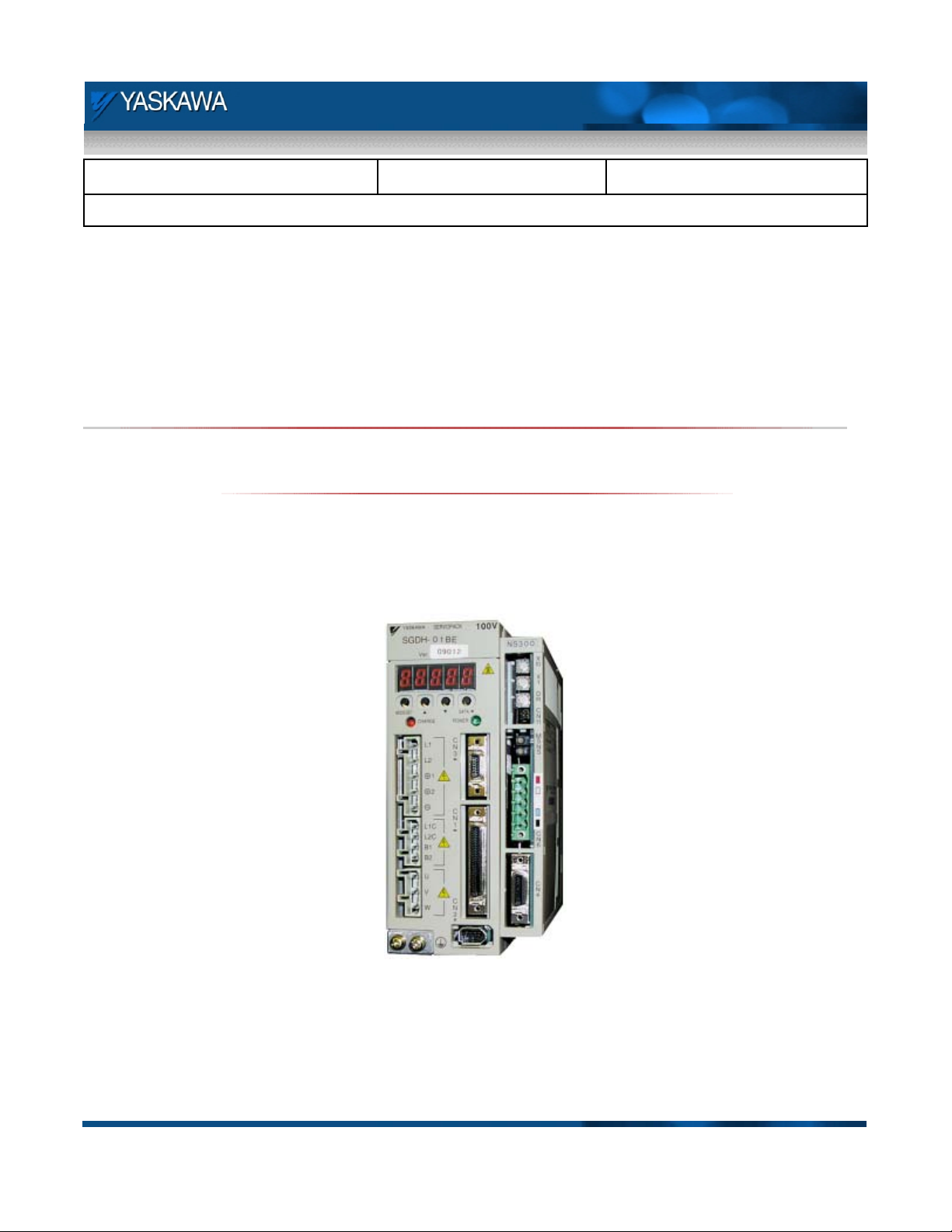
The setup used to write and test the example ladder is shown below. An MP940D was used as the DeviceNet
master, and NS300 demo was used as the test unit. Note that operation is identical on the NS500, except that
the PROFIBUS protocol is used instead of DeviceNet. Ladder code was written in the MPE720 MotionWorks
software environment, and local I/O of the MP940 was used to simulate PLC signals.
MP940D
Local I/O
NS300
Module
MP940D
Controller
Fig 1. Setup for Writing Example Master Ladder
Doc#: Copyright Yaskawa Electric America ©2004 May 9, 2007 Page 2 of 16
Page 3

Subject: Technical Note Product: NS300/NS500 Doc#: EM.MCD.05.106
Title: NS300/500 Master Ladder Example
Before Programming
Before beginning programming for the NS300/500 master ladder, be sure to do the following:
Configure communications in the PLC. Follow the setup procedure provided with the PLC for adding a
device to the scan list of the selected network. The NS300/500 requires 8 bytes in/out. It is
recommended to configure the second four bytes as data type long (or double-word) for convenience. If
using a PLC that requires a setup file, the DeviceNet and PROFIBUS files can be found as shown below:
Table 1. Network Configuration Files
Category NS300 NS500
Setup File
NS300(rotary).eds
NS300(linear).eds
NS500.gsd
Location www.yaskawa.com - search FAQ www.yaskawa.com - search FAQ
Configure communications in the NS300/500. This entails setting the DIP switches properly for
communications baud rate and network address. See the NS300/500 manual for proper settings.
Verify the functionality of E-stop, POT, and NOT on CN4 of the NS300/500. If using the hardware E-
stop, monitor the status of this bit using the NSxxx software to ensure that it is working as intended.
Disable this input if not being used by setting Pn81B, bit 0 = 0. Verify POT and NOT are connected
properly to the SGDH by monitoring these with the NSxxx software. If not using either of these signals,
they can be masked off by setting Pn50A.3 = 8, and Pn50B.0 = 8.
Test communications between the PLC and NS300/500. Make sure the two devices are
communicating by opening a watch window in the PLC software. Test the E-stop bit from the PLC (be
sure the E-stop bit at CN4 of the NS300/500 is set) and verify that a response is being received from the
NS300/500 as the bit is toggled. Spin the motor by hand and monitor motor position by observing bytes 4
thru 7 of the response message.
Doc#: Copyright Yaskawa Electric America ©2004 May 9, 2007 Page 3 of 16
Page 4

Subject: Technical Note Product: NS300/NS500 Doc#: EM.MCD.05.106
Title: NS300/500 Master Ladder Example
Register Summary
The chart below shows the assignment of the global and I/O registers used in the example program. Local
registers are used throughout the program, but are not listed in this chart. This chart contains the registers
accessed directly by the user.
Table 2. Example Master Ladder Register Addressing
MP940D Local I/O Inputs
User inputs to simulate PLC signals
Input Function Input Bit Bit Symbol Functionality
Input 0 IB00000 MB00000 PLC_ESTP N.C. E-stop
Input 1 IB00001 MB00001 PLC_SVON Enables Servo
Input 2 Alarm Reset IB00002 M B00002 PLC_ALARM_RESET Clears NSxxx Alarm
Input 3 Start IB00003 MB00003 PLC_COMMAND_START Starts motion command
Input 4 Direction IB00004 MB00004 PLC_DIR Selects forward/reverse
Input 5 Inc/Abs IB00005 MB00005 PLC_ABS_INC Incremental or absolute
Input 6 Hold IB00006 MB00006 PLC_HOLD Pauses motion command
Input 7 Cancel IB00007 MB00007 PLC_CANCEL Cancels motion command
/E-Stop
Servo On
PLC Co mm a n d B its
Bits to be controlled by PLC program
PLC Co mm a n d R e g is te r s
Command data loaded into these registers
Symbol
PLC_COMMAND_SELECT
PLC_RESPONSE_CO DE
PLC_FEED_SPEED
PLC_STEP_NUMBER ML00006 3
PLC_STATION_NUMBER ML00008 4
PLC_POINT_TABLE_ROW ML00010 5
PLC_TARGET_POSITION ML00012 6
PLC_PARAMETER_N UM BER
PLC_PARAMETER_D ATA
PLC_CURRENT_POSITION_SET ML00018 9
Register
MW00002 0
MW00003 1
ML00004 2
MW00014
ML00016
PLC_C O M M AND_ S ELE CT Se ttin g s
Value to be loaded for type of motion command
PLC_RESPONSE_CODE Settings
Determines meaning of response message
Follow response code settings as listed in user's manual.
Setting
10 Read Parameter
11 Write Parameter
12 Set Current Position
13 Set Zero Point
14 Read Alarm
15 Reset Module
Description
No operation
Feed
Step
Station
Point Table
Zero Point Return
Positioning
7
External Positioning
8
Notch Output Positioning
Multi-Speed Positioning
Doc#: Copyright Yaskawa Electric America ©2004 May 9, 2007 Page 4 of 16
Page 5

Subject: Technical Note Product: NS300/NS500 Doc#: EM.MCD.05.106
Title: NS300/500 Master Ladder Example
Programming the NS300/500 Master Ladder
Properly programming the network master controller of the NS300/500 is essential for success when
implementing one of these application modules. Most application issues identified in the field are the result of an
application program that does not adhere to the NS300/500 timing diagrams. This technical note is intended to
explain how the example master ladder program operates, and how it effectively eliminates common
programming mistakes. Following the principles described in this tech note will greatly reduce troubleshooting by
eliminating the majority of application issues. Three main issues are addressed; general program flow, best
practices programming, and proper command bit sequencing and interlocking. After addressing these issues,
specific highlights of the program are also discussed.
Doc#: Copyright Yaskawa Electric America ©2004 May 9, 2007 Page 5 of 16
Page 6

Subject: Technical Note Product: NS300/NS500 Doc#: EM.MCD.05.106
Title: NS300/500 Master Ladder Example
Program Flow
The first topic is general program flow. This program has been arranged so that it mimics the structure of the
command message. Three distinct sections of the program have been identified in the table below:
Table 3. Program Sections
Command Message Description Program Lines
Bytes 0-1 General Commands Lines 0-31
Bytes 2-3 Motion Command Bits/
Set/Read Parameter No.
Bytes 4-7 Command Data Lines 49-57
Organizing the program in this manner makes the ladder easy to navigate and easy to identify what is being
accomplished at any given line. In addition, an easy to navigate program makes troubleshooting at later dates
much easier. The table below identifies the main tasks to be completed in each section of the program.
Table 4. Program Section Tasks
Program Section Tasks
Lines 00-31
Bytes 0-1
General interlocking – emergency stop, alarm reset, servo
enable
Command identification – set/read (MOD)
Determining and loading the command and response
codes
Lines 32-48
Bytes 2-3
These two bytes are formatted differently for a motion
command versus a set/read command.
Motion command bit sequencing
Setting the proper motion command bit (FEED, HOME,
etc.)
Loading parameter number data for set/read commands
requiring parameter information
Lines 49-57
Bytes 4-7
Load the command data properly for the selected
command (motion or set/read)
Lines 32-48
Doc#: Copyright Yaskawa Electric America ©2004 May 9, 2007 Page 6 of 16
Page 7

Subject: Technical Note Product: NS300/NS500 Doc#: EM.MCD.05.106
Title: NS300/500 Master Ladder Example
Incorporating Best Practices
The second main topic is incorporating best practices programming into the ladder code. It is strongly
recommended to follow best practice programming recommendations, as these have been developed through a
wealth of application experience. Three main best practices are recommended for this program:
1. Write to each register/bit only one time in the program. Writing to registers in multiple locations is
highly discouraged. Use the waterfall technique to load registers with the proper values.
2. Avoid using set/reset coils. Set and reset coils can be hard to identify what has caused the current
state of the bit, making diagnosis very difficult. Instead, use latching circuits to latch and unlatch bits.
3. Force non-utilized command bits off. By forcing command bits that are not being used off, interference
between commands cannot occur. With proper interlocking, no two commands will be set together.
Each of these practices have been demonstrated in the example program. The first best practice is writing to a
register or bit only once. Errors can occur when registers are accessed multiple times, as improper data can
accidentally be loaded. When using the waterfall technique, data is loaded into the accumulator, the accumulator
is manipulated based upon logic conditions and required math operations, and then moved to the selected
register at the end of the section once all operations have been performed.
Load accumulator
with starting value
(i.e. zero, current
register value,
etc.)
Manipulate data
based on program
Actual register is
only loaded once
Manipulations only
Manipulated data
loaded into
selected register
logic
occur in
accumulator
Fig 2. Waterfall Technique
Doc#: Copyright Yaskawa Electric America ©2004 May 9, 2007 Page 7 of 16
Page 8

Subject: Technical Note Product: NS300/NS500 Doc#: EM.MCD.05.106
Title: NS300/500 Master Ladder Example
This technique is easily visible in the last section of code. Starting in line 49, the long accumulator is loaded with
zero. The starting value of the accumulator is recommended to either be the current value of the selected register
(load the accumulator with the register value), or the desired register value if no data manipulation occurs. Lines
50 thru 56 perform the manipulation by loading the accumulator based on the selected command, as well as
range check and limit functions for certain command types. Lastly, the actual output register to the NS300/500 is
then loaded in line 51.
Another added feature of using the waterfall technique is that important registers are updated each scan. In this
example, the output register is loaded with zero on the first scan after the user sets the command to no operation.
This is very useful as it eliminates any residual data that may otherwise cause command errors if the residual
data is out-of-range or improperly formatted for the ensuing command.
The second recommended best practice is to avoid using set/reset coils. Set/reset coils are never recommended;
these coils are extremely difficult to troubleshoot since identifying the condition that caused a set or reset may not
be visible. For this reason, latch circuits are always recommended. Latch circuits are recommended as they can
be used to easily identify the cause of the current state of the coil. An example of a latch circuit is the command
bit circuit shown on line 33 of the example master ladder.
Fig 3. Command Bit Sequencing Circuit
The coil is set on the rising edge of the PLC_COMMAND_START bit as long as the COMMAND_OVERRIDE and
READY contacts are satisfied. COMMAND_BIT latches itself in the middle and last rungs. In the middle rung,
the circuit will stay latched until the PRGS_FALL or SET_READ_COMMAND contacts open. In the last rung, the
circuit will stay latched as long as the PLC_COMMAND_START and SET_READ_COMMAND contacts remain
closed. If the command bit is set unexpectedly, monitoring this circuit will indicate exactly what is causing the coil
to remain on as the coil status is updated every scan.
Doc#: Copyright Yaskawa Electric America ©2004 May 9, 2007 Page 8 of 16
Page 9

Subject: Technical Note Product: NS300/NS500 Doc#: EM.MCD.05.106
Title: NS300/500 Master Ladder Example
The last recommended programming practice is to force off any non-utilized command bits. Two bits are provided
in order to modify the motion command by indicating a direction, using the DIR bit, or indicating that the move
should be absolute or incremental, using the INC bit. These bits are only valid for selected commands, and
otherwise have no significance. When a command is selected that renders these specific bits inactive, they
should be set off. This is shown below in line 41, which controls the DIR bit.
Fig 4. DIR Bit Circuit
The PLC_DIR bit commands the DIR coil. However, the DIR coil is only valid during feed, step, station, or point
table commands. If the PLC_DIR is set, but the current command is not of the commands that can utilize the DIR
command, then this bit is left off and properly follows the recommended practice.
Doc#: Copyright Yaskawa Electric America ©2004 May 9, 2007 Page 9 of 16
Page 10

Subject: Technical Note Product: NS300/NS500 Doc#: EM.MCD.05.106
Title: NS300/500 Master Ladder Example
Command Bit Sequencing
The last main topic is proper command bit sequencing and interlocking. One command bit circuit is used in this
program for all commands. The coil of the command bit circuit is then interlocked with the selected command to
set the appropriate command bit of the output message. The command bit circuit is shown below.
Fig 5. Command Bit Sequencing Circuit
As previously described, the COMMAND_BIT coil is set on the rising edge of the PLC_COMMAND_START bit as
long as the COMMAND_OVERRIDE bit remains low and the READY bit remains high. READY is an input from
the NS300/500 indicating that a command can be executed, and COMMAND_OVERRIDE is a coil in the program
that is used to lockout any commands from being executed under certain conditions. The
COMMAND_OVERRIDE circuit in line 32 is shown below.
Fig 6. Command Override Circuit
Doc#: Copyright Yaskawa Electric America ©2004 May 9, 2007 Page 10 of 16
Page 11

Subject: Technical Note Product: NS300/NS500 Doc#: EM.MCD.05.106
Title: NS300/500 Master Ladder Example
The COMMAND_OVERRIDE coil is set in any one of four conditions. The first occurs if the servo is disabled as
reported by the SVON_R response bit from the NS300/500. A normally closed contact of
SET_READ_COMMAND is also included in this first rung. During set/read commands, the NS300/500 allows the
servo to be disabled. The second and third conditions for setting the command override occur in an over-travel
condition. It may be beneficial to the user to add an additional interlock to this circuit in order to jog back across
the over-travel sensor.
The last condition occurs after the command has actually been activated. Completed motion commands are
identified on the falling edge of the PRGS bit. Some conditions occur in which the PRGS bit never cycles,
eliminating a falling edge of the PRGS bit from occurring. This last rung of logic is used to clear the command bit
in cases where the PRGS bit never cycles. If the NS300/500 reports that the motor is in position (INPOS and
NEAR), and the PRGS bit is low (meaning a falling edge cannot occur), then the motor is in position. If this
occurs while COMMAND_BIT is still high, a timer checks for 50ms and then sets COMMAND_OVERRIDE in
order to clear the latched COMMAND_BIT. This can occur in the following two conditions:
1. Commanding the servo to move to its current position. PRGS bit never goes high because the servo is
already in position and no move is required.
2. The move distance is short, so the timing of the PRGS bit is less than one transmission cycle.
Once COMMAND_BIT is set, the coil must be latched in order for the coil to remain active. The bottom two rungs
of the COMMAND_BIT circuit are shown above (also from line 33). The middle rung is selected as the latch
circuit for motion commands (non set/read) and the bottom rung is selected as the latch circuit for set/read
commands.
Fig 7. Command Bit Latch Circuits
Doc#: Copyright Yaskawa Electric America ©2004 May 9, 2007 Page 11 of 16
Page 12

Subject: Technical Note Product: NS300/NS500 Doc#: EM.MCD.05.106
Title: NS300/500 Master Ladder Example
When a set/read command is active (bottom rung), the coil will remain latched as long the
PLC_COMMAND_START bit is held on. When a motion command is active (middle rung), the circuit will remain
latched until the PRGS_FALL bit is set, opening up the normally closed contact. The PRGS_FALL bit is the oneshot falling edge of the PRGS response bit, shown in line 34 below. The falling edge of the PRGS bit indicates
the NS300/500 has completed the motion profile, and COMMAND_BIT can be removed.
Fig 8. PRGS Falling Edge Circuit
Once COMMAND_BIT is set, ANDing COMMAND_BIT with the selected command sets the specific command
bit. An example of this is shown below. Command bits for feed, step, and station are shown in lines 35 thru 37
(this operation occurs on lines 35 thru 40). When the selected command and COMMAND_BIT are both active,
the coil will be set. This allows one command bit circuit to control all of the commands as well as preventing
multiple commands from being active together. Note that for feed, PLC_COMMAND_START must be active to
set the output. This has been added to provide jog functionality by stopping motion whenever the command is
removed.
Fig 9. Setting Individual Command Bits
Doc#: Copyright Yaskawa Electric America ©2004 May 9, 2007 Page 12 of 16
Page 13

Subject: Technical Note Product: NS300/NS500 Doc#: EM.MCD.05.106
Title: NS300/500 Master Ladder Example
Additional Topics
In addition to the three main topics described above, a handful of specifics in the program are worth noting. Here
is a list of these items:
Servo-on latch circuit
Bit/byte manipulation for response/command codes in output bytes 0-1
Working registers and selecting the proper data to place in output bytes 2-3
Using MOD_R to load data with set/read commands
Servo on latch circuit
The servo on latch circuit is shown below. SVON can be enabled when the NS300/500 is not indicating an
emergency stop, the PLC_ESTP bit is set, and main power is applied to the servo amplifier. The coil is set on the
rising edge of the PLC_SVON bit. Note that the READY bit response from the NS300/500 must be active on the
rising edge of the PLC_SVON bit. The READY bit is only included in setting the coil, but does not participate in
latching the SVON coil. This setup is required as the READY bit changes state during the execution of the SVON
command. Once the coil is set, it is unlatched either by clearing the PLC_SVON command, by an emergency
stop occurring in either the PLC or the NS300/500, or if main power is removed from the servo.
Fig 10. Servo On Latch Circuit
Bit/byte manipulation for response/command codes in output bytes 0-1
Bit and byte manipulation is required when loading the response and command codes into output bytes 0-1. This
is necessary as the controller used in the example works in bit or word data types, and output bytes 0-1 use bit
and nibble data types for the associated commands. The flowchart on the following page describes this process.
Included with the flowchart are contents of the registers as the code is executed. Note: the first step of the
flowchart, loading the response code to MW00003, is completed by the user in other portions of the PLC code.
Doc#: Copyright Yaskawa Electric America ©2004 May 9, 2007 Page 13 of 16
Page 14

Register Legend
Byte 0, Upper Nibble Byte 0, Lower Nibble
Byte 1, Upper Nibble Byte 1, Lower Nibble
Response code
loaded to
MW00003
Response/Command Code
Lines 20-31
Lines 20-21
Accumulator_W (DW00026)
0 Response Code
0 0
Accumulator_W (DW00026)
Response Code 0
0 0
Accumulator_W (DW00026)
Response Code Command Code
0 0
Response_Command_Code
(DW00012)
Response Code Command Code
0 0
Set/Read
Yes
command?
No
Load response
code to
accumulator
Shift response
code to upper
nibble of byte 0
Load command
code to lower
nibble of byte 0,
using OR
command
Store data to
Response_Command_Code
Line 22
Lines 26-27
Load zero for
response code to
accumulator
Command co de
loaded to
NS300_Command
Properly modi fy
NS300_Command
based on type of
command
Lines 23-25
Accumulator_W (DW00026)
MOD, ALRST, ESTP SVON, C_STRT
Current Response
Code
Current Command
Code
Accumulator_W (DW00026)
MOD, ALRST, ESTP SVON, C_STRT
0 0
Load current
output to bytes 0-1
into accumulator
Mask off current
response and
command codes
Line 28
Line 29
using AND
Accumulator_W (DW00026)
MOD, ALRST, ESTP SVON, C_STRT
Response Code Command Code
Load response and
command codes to
accumulator using OR
NS300_BytesOut_0_1 (OW00030)
MOD, ALRST, ESTP SVON, C_STRT
Response Code Command Code
Page 14 of 16
Fig 11. Process for Loading Response and Command Codes
Load accumulator
to output bytes 0-1
Line 30
Line 31
Perform byte swap on
Response_Command_Code to
get data to byte 1 of register
Response_Command_Code
(DW00012)
0 0
Response Code Command Code
Page 15

Subject: Technical Note Product: NS300/NS500 Doc#: eng.MCD.05.106
Title: NS300/500 Master Ladder Example
Working registers and selecting the proper data to place in output bytes 2-3
Loading the proper data into output bytes 2-3 requires the use of an accumulator. For motion commands, output
bytes 2-3 are bit settings, but for set/read commands, output bytes 2-3 combine to become a word type register.
If the command is a set/read command and, more specifically, a parameter read or parameter write command,
the parameter value from MW00014 is loaded to the accumulator once the MOD_R response bit from the
NS300/500 is acknowledged. If the command is any other set/read command, the accumulator is loaded with
zero. Motion command bits are set in a working register, DW00016, and then loaded to the accumulator for
motion commands.
Motion command bits set in
NS_Bytes_2_3_Working
DW00016
Accumulator loaded with
NS_Bytes_2_3_Working
Accumulator
loaded with zero
Set/Read
No Yes
command?
Line 46
Parameter
Read/Write?
No
No change to
accumulator
(still zero)
Parameter number for Set/
Read commands loaded to
MW00014
Yes
MOD_R
active?
Accumulator
loaded with
parameter number
Line 47
Line 48
Accumulator loaded into
NS300_BytesOut_2_3
Fig 12. Output Bytes 2-3 Data Selection Process
May 9, 2007 Page 15 of 16
Page 16

Subject: Technical Note Product: NS300/NS500 Doc#: eng.MCD.05.106
Title: NS300/500 Master Ladder Example
Using MOD_R to load data with set/read commands
When using either the parameter read or parameter write set/read commands, output bytes 2-3 should not be
loaded with parameter data until the NS300/500 has acknowledged a set/read command is to be performed via
the MOD_R response bit. The MOD bit of the command message indicates a set/read command, and the
response is sent by the NS300/500 through MOD_R. This interlocking is shown for both output bytes 2-3 as well
as output bytes 4-7. Line 47 demonstrates this interlock for output bytes 2-3, and lines 55 and 56 show this for
parameter read/write commands, in addition to the set current position command.
Fig 13. MOD_R Interlocking for Output Bytes 2-3
Fig 14. MOD_R Interlocking for Output Bytes 4-7
May 9, 2007 Page 16 of 16
 Loading...