

Page 1

‘ymSjÿÿS¥
|;
p.Wÿ?
INSTRUCTIONS
umW
(TAS9CAWA
,A
•m&e
S&
•
TOE-C843-8
30
ASBgBmBBSBBBi
.
YASNAC
\
Efil/$\/2n
i
sa
#>
:-
f/iOfougftfy
tor
flefo/e
read
future
/rt/f/a/
fftese
and
reference
operaf/on
/nsf/ucfcons
re/a/n
J&&&SWX&BaS&
j
jP.
This
manual
display
acter
YASNAC
For
operation
optional),
31)
separately
This
of
tures
dagger.
a
with
MX2,
refer
MX2
refer
YASNAC
primarily
is
(basic)
programming,
of
14”
the
to
provided.
manual
to
For
the
applies
MX2.
machine
intended
to
give
CRT
instruction
to
The
specifications
the
tool
operators
operation
character
manual
the
basic
optional
builder’s
with
9”
instructions
and
display
(TOE-C843-8
and
features
your
of
manual
CRT
char¬
for
maintenance.
(ACGC,
optional
are
fea¬
marked
YASNAC
w
:
’
C
0/000
50/0
V’
000(30
00
SK
L
YASNAC
9"
with
*,
P:»V
MX2
CRT
Q
Operator’s
Character
r
V
.
n
Display
N
O
x
V
I
J
M
S
E
L
Station
B
I
G
I
z
K
|
T
I
/
I
C
A
w
V
u
p
R
Q
H
F
D
e
9
7
s
4
e
1
3
2
0
273
681
'/>OSJTlbMCUNJV£*S*L>
r
;
Y
;
7
Z
vM9.:704
;ÿ5
Page 2

PREFACE
reading
When
information
possible
the
operation.
this
manual
control.
functions
The
determined
control.
NC
the
machine
over
ority
The
illustration
be
used
function.
names,
and
.
1
2.
2.1
2.2
2.3
2.4
2.5
2.6
2.7
2.8
2.
2.10
2.11
3.
3.1
3.2
3.3
3.4
4.
CHARACTER
4.1
4.2
4.3
4.4
4.5
4.6
4.7
4.8
5.
5.1
5.2
5.3
this
contained
contingency
Any
should
and
performance
combination
a
by
For
operation
builder's
tool
this
manual.
of
for
For
your
refer
reference
detailed
to
INTRODUCTION
PROGRAMMING
Format
Input
Program
Coordinate
Traverse
Spindle-Speed
Tool
Tool
Miscellaneous
9
Preparatory
User
user
PART
Tape
Programming
Part
Part
NC
Pushbuttons,
Power
Display
Tape
Loading
Edit
Supplement
Tape
TAPE
Tape
Tape
Portable
Number
Function
Compensation
Message
Macro
PROGRAM
Code
Program
Program
OPERATOR'S
On
and
Jnput/Output
Part
149
/
Verifying
READER
Reader
Reels’ÿ
manual
herein
which
operation
be
not
machine
array
machine
1
/
Word
and
Feed
Function
(T-
Functions
Function
Display*
(C65
121
/
121
/
Tape
Tape
DISPLAY
Lamps
Operation
/Off
Writing
programs
to
Data
Compartment
160
/
Reader
Tape
keep
does
might
attempted
of
of
your
manual
control
m
of
tool
1
/
1
/
Sequence
and
6
/
Functions
Function)
15
/
(c-Function)
C66)
and
TAPE
Punching
Handling
STATION
/
and
Operation
Operations
Input/Output
156
/
159
/
in
mind
cover
not
be
met
described
not
with
NC
machine
as
machine
NC
shall
station
and
machine,
take
understanding
operator'ÿ
builder's
TABLE
Number
10
/
(S-Function)
14
f
(M-Function)
93
/
94
/
CODING
124
/
124
/
WITH
125
125
Keys
/
130
/
J31
/
of
NC
Into
Memory
Interface
159
/
163
Unit*/
that
every
during
the
the
pri¬
should
devices
manual.
13
/
/
16
22
/
121
/
9”
DATA/
146
/
the
Unless
ples
m
are
the
OF
CONTENTS
6.
1
6.
6.2
6
f
7.
7.1
2
7.
7.3
7.4
Compensation
5
7.
7.6
7.7
Operation
7.8
7.9
Operation
7.10
7.11
8.
CRT
8.1
8.2
8.3
8.4
8.5
8.6
143
APPENDIX-1
APPENDIX-2
151
/
APPENDIX-3
COMPENSATION
APPENDIX-4
OUTPUT
APPENDIX-5
otherwise
the
to
apply
shown
•
Absolute
•
Reference
(Return
matic
•
Dimensions:
MACHINE
Switching
Operation
OPERATION
Inspection
Turning
Manual
Preparation
Preparation
Operation
Manual
Automatic
MDI
Preparation
Turning
to
return)
on
Operation
and
Operation
188
/
Operation
189
/
off
MAINTENANCE
Routine
Battery
Power
Thermal
Molded-case
Trouble
Inspection
Replacement
Circuit
Overload
Causes
SIGNALS
specified,
description
this
in
Point:
Zero
Zero
reference
:
in
CONTROL
on
Units
Procedure
PROCEDURE
Before
Power
for
Stored
Stored
Automatic
for
in
Tape
Interrupting
Operation
Interrupting
for
Turning
Power
/
Breaker
circuit
and
LIST
OF
LIST
OF
STORED
226
/
OF
LIST
/
LIST
OF
of
manual.
Point
zero
MM
STATION
the
Control
176
/
Turning
186
/
186
/
Leadscrew
Stroke
Operation
and
Memory
in
MDI
off
189
/
19J
Schedule
194
/
and
of
Relay
Breakers
Remedies
SETTINC
PARAMETER
LEADSCREW
STANDARD
230
ALARM
the
programming
by
Station
186
/
Power
on
Limit*
Mode
Automatic
Mode
Automatic
Power
191
/
Fuses
Servo
(MCCB)
/
“N
CODES
following
manual
166
/
/
Error
187
/
/
/
188
/
189
/
195
/
Unit
198
NUMBERS
NUMBERS
ERROR
INPUT/
/
186
187
188
/
166
197
/
/
198
240
rules
exam¬
and
/
/
auto¬
200
206
APPENDIX-6
LIST
OF
ADDRESS
CHARACTERS
252
/
Page 3

INDEX
APPENDIX
.
APPENDIX
....
C
•
Chapter
.
.4.
••
•
•
2
2
2
4
4
8
2
2
2
2
2
6
7
2
6
6
8
8
4
2
4
2
3
2
8
8
2
2
4
2
4
2
8
2
2
4
4
4
6
4
4
4
2
2
4
6
6
2
I
Subject
A
Absolute
Absolute
Address
ADDRESS
ADDRESS
Address
Alarm
Alarm
ALARM
Alarm
Alarm
Argument
Automatic
Automatic
Automatic
AUTOMATIC
Automatic
Automatic
AXIS
B
Battery
BATTERY
Breakpoint
Buffer
C
Cable
Canned
Cautions
Circle
Circuit
Circuit
Circular
Circular
(M97/M96)
Command
Considerations
Constant
Control
Control
Coordinate
COORDINATE
CRT
Current
CURSOR
CYCLE
D
DATA
Data
Input
DATA
Decimal
Display
DISPLAY
DISPLAY
DRY
RUN
Dwell
Zero
/Incremental
and
CHARACTERS
Keys
Search
Code
Display
Codes
CODES,
Message
Number
Designation
Acceleration
Centering
Coordinate
Return
Tool
INTERLOCK
REPLACEMENT
Function
Register'*’
Connector
Cycles
in
Programming
Cutting
Breaker
Breaker
Interpolation
Path
t
Data
Display
Commands
Panel
Word
Character
Position,
Keys
START
INPUT
/Output
Keys
Point
and
Write
AND
LOCK
Switch
(G04)
(G92)
Point
Programming
Function
and
Display
of
OPERATION,
length
(G73,
(G12,
Mode
Display
and
•
WORD
Display
Pushbutton
/OUTPUT
Programming
WRITING
/MACHINE
Characters
Remedies
OF
LIST
Macros
User
Function
System
to
Reference
Measurement
Input
Specifications
G74,
G13)+
for
Servo
of
Composite
(G02,
On/Off
Remarks
•
*
Displaying
INTERFACE,
Interface
of
Local
,
Programming
,
OF
LIST
#8000
by
and
Deceleration
(G36,
Settingt
PREPARATION
Point
•
*
G77,
G76,
....
•
•
Control
Control
G03)
Tool
on
User
for
and
and
Lamp
to
be
Variables
OPERATION
LOCK
Switch
(G90,
Command
G37)T
....
(G28)t
+
G80
Power
Radius
Macros
Resetting
SUPPLEMENT
used
and
•
of
*
G91)
•
•
•••
•
FOR
G89,
to
Supply
Compensation
* *
*
•
•
Setting
Common
G98,
Unit
TO
•
of
Variables
G99)+
Section
2.9.30
2.9.29
6
.
2.1.1
*
.
4.1.4
4.3.10
4.3.12
5
2.10.1
2.11.10
2.11.2
2.4,6
2.9.18
6.2.2
7.5
2.9.14
6.2.3
8.6.2
• •
6.1.29
8.1.4
8.2
4.3.11
2.1.5
4.7.4
2.9.28
3.2.3
2.9.9
8.3.5
8.3.1
2.9.4
2.8.6
4.3.2
2.11.9
4.3.1
2.11.6
8.1.2
2.3.1
2.3
4.1.2
4.3.4
4.1.8
6.1.2
4.7
4.7.2
4.1.5
2.1.3
11.8
2.
4.3
6.1.21
6.1.20
2.9,6
Page
85
85
3
252
.....
127
141
142
198
240
93
116
96
----
13
----
40
177
187
37
178
174
----
193
194
142
5
153
....
74
123
29
196
195
25
20
132
••'•113
131
no
192
7
6
126
135
128
166
151
151
127
5
113
131
171
171
28
i
ii
Page 4

Subject
E
EDIT
EDIT
Keys
EDIT
LOCK
Editing
El
/ISO
A
EMERGENCY
Stop
Exact
Exercises
EXTERNAL
F
FI-Digit
FEED
HOLD
Feedrate
Feedrate
FEEDRATE
FEEDRATE
Axis
5th
4th
Axis
5th
Axis
Axis
4th
FUNCTION
Fuse
Blowing
for
Fuse
of
Fuses
FusesofPower
G
Codes
C
G06)
(GOO,
(G01)
Linear
G03)
(G02,
(G02,
GQ3)
(G04)
Dwell
(G09,
G61,
(G10)
Tool
(G12,
G13)
(G17,
G18,
G21)'''
(G20,
(G22,
G23)
(G25)+
(G27)+Reference
(G28)yAutomatic
(G29)‘
Return
(G
2nd,
30)ÿ
31)
<G
SkipÿF
‘
(G36,
G
(G38)+Z-Axis
(G40,
G41,
(G43,
G44,
(G45
to
(G50,
G5
(G52
to
(G52
to
(G60)‘
Unidirectional
(G70f
G71,
(G73,
G74,
(G80,
G81
(G90/G91)
(G92)
Programming
(G100
through
Switch*
Operation,
Auto-
STOP
(G09,
User
of
DECELERATION
Programming
Pushbutton
Function)
(F-
1/10
OVERRIDE
OVERRIDE
Controit
Control
Neglect
Neglect
Keys
(Alarm
Servo
Composite
and
Groups,
Positioning
Interpolation
Circular
Helical
+
G64)
Offset
+
Circle
G19)
Inch
+
Stored
Program
from
3rd
unction
37)ÿ
Automatic
Reference
G42)+Tool
G49)*Tool
G48)
Tool
DÿScahng
G59)TWork
G59JÿWork
G72)
G76,
)*
Output
Absolute
102)+
Select
G61,
Macro
.....
+
Input
Input
Control
Input
Exact
Value
Cutting
Plane
/Metric
Copy
Point
Return
Reference
and
Position
Function
Coordinate
Hole
G80
for
/Incremental
of
Summary
Pushbutton
G64)
....
+
and
CANCEL
Switch
331
No.
Power
Control
Unit
of
Last
Interpolation
Interpolation
Stop
Designation
Designation
Designation
Stroke
Coordinate
High-Speed
Limit
Check
Reference
to
Reference
4th
Centering
Surface
Radius
Length
Offset
Approach
Pattern
G89,
to
External
Absolute
of
Signals
Input
Lamp
Switch
*
- - -
...
335)*
to
Unit
Power
Supply
.
...
*
Zero
Function
Offset
Compensation
Compensation
System
System
Cycles
G99)
G98,
Motion
Programming
Zero
Cutting
.
*
by
Point
Point
Setting
Setting
Point
INDEX
+
...
Unit
G
Code
....
Return
C
A*
Canned
Feature
.
* *
* *
*
B.
Cycles
•
*•*
Chapter
4
4
6
4
3
6
2
2
6
2
6
2
2
6
6
2
2
6
6
4
8
8
8
8
2
2
2
2
2
.
.
•
*
*
*
•
•
*
•
-
•
•
2
2
2
2
2
2
2
2
2
2
2
2
2
2
2
2
2
2
2
2
2
2
•
2
2
-
2
*
«
2
*
2
*
2
Section
•
.
•
*
•
•
•
.
.
.
.
-
*
-
•
.
.
-
-
-
•
-
.
-
-
-
•
*
•
•
•
*
.
*
2.9.17
2.9.20
2.9.
2.
2,
2.9.
2.9.24B
2.9.25
2.
2.
2.9.27
2.9.29
2.9.30
2.9.
6
4.
4.1.10
6.1.28
4.8.4
3.1.2
6.1.4
2.9.7
2.
11.
6.
30
1.
2.4.4
6.1.3
2.4.2
2.4.3
6.1.13
6.
1.12A
2.3.6--
2.3.5*-
6.1.22C
6.1.22B
4.1.3
8.4.1
8.3.4
8.3.2
8.3.3
2.9.1
2.9.2
2.9.3
2.9.4
2.9.5
2.9.6
2.9.7
2.9-8
2.9.9
2.9.10
2.9.11
2.9.12A
2.9.12B
2.9.13
2.9.14
2.9.15
2.9.16
2.9.18
19
2.9.
21
9.22
23
9.
24A
9.
26
9.
28
31
Page
•
*
*
149
128
174
.
158
•
121
.
166
11
.
.
.
.
.
.
.
.
.
••
.
.
.
.
28
116
174
11
•
166
11
12
-
170
168
9
8
172
172
126
197
196
195
196
22
-
24
24
25
27
28
28
-
29
-
29
32
32
33
34
36
37
38
39
39
40
42
42
56
58
63
65
67
70
71
74
73
85
85
86
iii
Page 5
INDEX
..
.
Chapter
2
6
6
6
2
2
2
2
2
2
4
8
4
4
7
4
4
1
-
6
6
6
3
2
2
2
4
4
2
2
2
2
2
2
2
2
2
2
6
6
8
8
6
7
7
6
6
6
2
2
7
7
.
4
6
2
2
2
6
Subject
Codes)
and
H
H-
HANDLE
HANDLE
HANDLE
Helical
High-Speed
Hole
I
Inch/Metric
Input
INPUT
Inputting
D-function
AXIS
Dial+
Dials
Interpolation
Pattern
Format
FORMAT
Setting
Input/Output
Input
/Output
Inputting
INSPECTION
Interface,
Internal
INTRODUCTION
J
JOG
JOG
JOG
Keeping
K
L
Label
Least
Linear
LOADING
Loading
(MOO,
f
M
(M90
(M91/M90)t
(M93/M92)t
(M95/M94)
(M97/M96)t
Compensation
(M98/M99)
M
Codes
M
Codes
Codes
M
M-FUNCTION
MACHINE
Maintenance
Tool
Type
Toggle
FEEDRATE
FEEDRATE
Pushbuttons
NC
Skip
Function
Input
Increment
Interpolation
PART
Part
M01,
M02,
M199)
to
Program
Multi-Active
Mirror
Circular
Subroutine
for
for
,
Other
CONTROL
(H,
Select
(Manual
Simultaneous
for
Cutting
Cycles
Designation
Data
Signals
Signals,
Offsets
BEFORE
and
Switches
OVERRIDE
Switch
Tape
*
PROGRAMS
Program
M30)
Codes
M
Image
C
Internal
(MOO,
Stop
LOCK
Before
Call,
D
witch
S
Pulse
(G02,
Feature
G71,
(G70.
by
and
Displaying
from
TURNING
Functions
‘
*
and
Least
(G01)
Tape
Codes
M
for
Internal
Interruption
Registers
On/Off
Mode
Path
Program
Processing
M01,
Switch
STATION
t
Generator)
G03)t
(G100
G
Parameter
SWITCH
into
M02,
(Auxiliary
*•* *
Control
G72)t
Code
-
Tape
ON
of
Output
INTO
for
On
On
(M90
• •
*
through
(G20,
On
/Off
.....
POWER
MEMORY
Memory
Stop
Processing
/Off
On
/Off
on
/Off
to
M30)
Function
of
up
0102)*
G21)t
Data
of
• •
Increment
Tool
99)
Ml
to
•
•
.
....
Radius
Lock)
Three
•
•
-
* *
•-•
Axes!*
‘
MAINTENANCE
MANUAL
MANUAL
MANUAL
TION
MANUAL
MANUAL
Manual
Maximum
Message
MDI
MDI
MEM
MIRROR
Mirror
Miscellaneous
ABSOLUTE
OPERATION
OPERATION
PULSE
REFERENCE
Return
Programmable
Display
MODE,
AUTOMATIC
OPERATION
(Memory
DATA
IMAGE
On/Off
Image
MISCELLANEOUS
SELECT
MODE
Switch
INTERRUPTING
MULTIPLY
POINT
Reference
to
Control-Out
by
INTERRUPTING
Data)
SELECTOR
AXIS
Function
(M95/M94)
FUNCTIONS
Switch
Select
RETURN
Point
Dimensions
OPERATION
Keys
(B-Function)
AUTOMATIC
Switch
*
Switch
and
Control-In
...
IN
AUTOMATIC
Switch
(M-FUNCTION)
.
,
t
2Nd
OPERA¬
t
OPERATION
.
*
’
Section
2.7.3
6.1.6
6.1.5
6.1.8
2.9.5
2.9.31
2.9.26
2.9.11
2.1.1
2.1
4.4.2
8.6.3
4.3.13
4.4.1
7.1
4.7.1
4.3.8
6.1
6.1.10
6.1.9
3.4.2
2.
1.4
2.3.7
2.9.3
4.5
4.5,1
2.8.1
2.8,2
2.8.
2.8.4
2.8.5
2.8.6
2.8.7
2.8.2
2.8.1
2.8.
6.1.23
8.6.4
6.1.24
7.2
7.7
6.1.7
6.1.15
6.2.1
2,3.8
10.2
2.
7.8
7.9
4.1.11
6.1.25
2.8.5
2.8.9
2.8
6.1.1
.
.
12B
3
8
—
..
•
Page
15
167
-
•
167
168
*
27
86
71
•
32
144
I
1
198
143
143
.
186
•
151
141
•
1
170
-•
168
168
124
5
9
24
146
146
16
17
17
17
17
20
20
17
16
21
173
166
199
191
173
186
188
167
170
176
10
93
188
189
1
128
173
17
*
21
16
166
iv
Page 6
INDEX
Subject
MOLDED-CASE
M
Multi-
Active
Multi-
Active
H
NC
OPERATOR'S
NC
Tape
NC
Tape,
Tape
NC
NEXT
Key
O
On-Line
Operation
OPERATION
OPERATION
Operations
Operation
Optional
OPTIONAL
OPTIONAL
ORG
(Origin)
Output
Overload
Overview
P
PAGE
Keys
Paper
Tape
PARAMETER
Parameters,
Part
Program,
Part
Program
Part
Program
Part
Program
Part
Program
Part
Program
PART
PROGRAM
PART
PROGRAM
PROGRAM
PART
Part
Program
PART
PROGRAM
Part
Program
Part
Program
Part
Program,
PART
PROGRAMS
Plane
Designation
Playback
Portable
Positioning
POWER
POWER
Power
On
PREPARATION
PREPARATORY
Process
Program
Program
Program
PROGRAM
PROGRAMMING
PROGRAMMING
Registerst
Registers
Check
Keeping
Punch
Diagnostics
Commands
PROCEDURE
PROCEDURE
using
Time
Block
BLOCK
STOP
Keys
for
External
(Alarm
of
User
Select
NUMBERS
Displaying
Block,
Block,
by
Display
Form,
Tape
Tape,
to
Function‘d
Reader
Tape
(GOO,
CIRCUIT
ON
/OFF
Pushbuttons
/Off
Sheet
CopyT(G25)
Interruption
Number
NUMBER
CIRCUIT
STATION
Data
Display
(/l-/9)
Skip
SKIP
Switch
Motion
No.
351
Macro
,
Adding
Deleting
Modifying
,
MDI
Loading
General
TAPE
TAPE
TAPE
into
TAPE
Verifying
Paper
Tape,
Making
Addition
INTO
(G17,G18,G19)
Unit'd
GQ6)
BREAKER
OPERATION
TURNING
FOR
FUNCTION
On
AND
BREAKERS
/Off
WITH
/Output
(M93/M92)+
CRT
9"
*
Interface
On
Input
+
Switch
081)ÿ
(G80,
355)
to
Body
OF
LIST
Writing
and
...
PUNCHING
CODING
HANDLING
Memory,
PUNCHING
MEMORY,LOADING
/Off
SEQUENCE
Loading
.....
Outputting
to
FUSES
AND
POWER
OFF
(C-FUNCTION)
(M91/M90)
NUMBER
(MCCB)
•
-
CHARACTER
•
*
....
....
•*•
*•*
+
Chapter
8
.
2
•
2
DISPLAY
•
*
•
*
.
-
•
4
3
3
3
4
8
2
6
7
•
4
*
4
2
6
6
4
2
8
2
4
3
APPENDIX
4
4
4
4
4
4
3
*
3
3
3
4
3
4
4
4
4
2
6
5
2
8
4
4
7
2
3
2
*
2
2
2
3
2
2
•
•
*
•
*
•
• •
* *
*
•
•
•
•
•
Section
•
8.5
.
2.1.6
2.8.4
*3.3.3
*
3.4.2
*3.3.2
*
4.1.6
•
8.6.1
2,11.5
*
•
6.2
•
4.7.5
*
4.3.9
*
2.2.3
6.1.19
•
6.1.18
•
4.1.9
*2.9,28
*
8.4.2
*
2.11.3
*
4.1.7
*
3.3.1
*
4.3.7
*
4.6.4
•
4.6.2
•
4.6.3
*4.5.3
4.6.1
•
3.2.2
*
3.3
3.4
*
4.5.1
‘3.3
•
4.8.3
•
4.4.
•
4.5.2
•4.5
•
2.9.10
•
6.2.5
5.3
•
•
2.9.2
*
8.3
•
4
•
4.1.1
•
7
*
2.9
*
3.2.1
.
2.9.12B
*
2.8.3
*2.2.1
*
2.
*
3.2
Page
198
5
17
125
.....
124
124
124
127
198
••••108
176
186
155
141
6
171
••••170
----
128
73
197
----
97
128
124
206
.....
139
150
*
•••149
150
*••ÿ148
149
123
.....
124
121
124
146
124
5
2
10
2
156
144
147
----
•
146
32
183
163
24
195
130
126
.....
189
22
121
34
17
----
6
6
121
1
v
Page 7

INDEX
APPENDIX
....
APPENDIX
*
APPENDIX
Chapter
.
.
«
-
•
*
.
•
.
.
.
6
4
2
6
2
6
2
2
4
4
4
2
8
2
2
2
2
8
4
4
4
4
4
2
2
2
6
2
6
2
3
6
7
2
2
6
2
2
5
7
3
3
4
4
5
8
5
5
5
5
5
4
Subject
P
Program
PUSHBUTTONS,
R
Rapid
Traverse
RAPID
Reference
REFERENCE
Reference
Registration
Registered
Remote
RESET
Return
ROUTINE
S
S2-Digit
S5-Digit
Scaling
Sequence
Servomotor
Setting
Setting
Setting
Setting
SETTING
Setting
Simultaneously
Simultaneously
Simultaneously
SINGLE
Skip
Function
SPINDLE
SPINDLE-SPEED
Splicing
STANDARD
START
STORED
STORED
STORED
Stored
Subroutine
SWITCHING
T
T2-Digit
T4-Digit
Feed
Tape
TAPE
AND
Code
Tape
T
CODE
APE
TAPE
FEED
TAPE
INPUT
Tape
Reader
Reader
Tape
TAPE
READER
TAPE
READER
Reels,
Tape
Reels,
Tape
REELS
TAPE
Restart
TRAVERSE
Power
Key
from
Programming
Programmingt
Function
and
Data
Data
Data,
+
LAMPS
Rate
Check
Point
POINT
Return
Point
of
User
Program
On
/Off
Reference
INSPECTION
Number
(G50,
andDCMotor
Parameter
and
Parameter
and
Parameter
Displaying
NUMBERS.
of
Baud
Rate
Controllable
Controllable
Controllable
BLOCK
NC
LOCK
Stroke
Switch
(031)
SPEED
OVERRIDE
FUNCTION
Tape
INPUT
Input
LEADSCREW
LEADSCREW
STROKE
Limit
Program
UNITS
UMIT
Programming
Programmingÿ
Switch
and
MEMORY
.
*
and
SYSTEM
/OUTPUT
. .
COMPARTMENT
Handling
Handling
+
AND
OVERRIDE
RATE
(G2?)
Lamps+
(G30)+
Macros
Number,
Pushbuttons
Zero
SCHEDULE
G51)+
Tape
UST
and
+
/OUTPUT
(or
Switch)
ERROR
ERROR
,
+
(G22,
(M98,
ON
THE
System
MODE,
No.
OPERATIONS
.
inch
8-
6-inch
KEYS
+
.2nd,
Display
(G29)+
Spindle
for
Verifying
Data,
Inputting
to
Data
and
OF
Others
Axes
Axes
Axes
Switch+
Paper
Writing
of
Serial
of
Four-
of
Three-
of
(S-FUNCTION)
SIGNALS,
+
COMPENSATION
COMPENSATION
PREPARATION
G23)+
M99)
CONTROL
No.
Switch
OPERATION
Switches
.
.
.
.
.
Switch
3rd
of
•
•
• •
•
•
Five-
UST
STATION
NC
OF
and
* *
«
•
• •
*
Tape,
Interface
axis
axis
axis
FOR
IN
....
DATA
•
*
•
4th
........
Outputting
Control
Controlÿ
Control
.
•
OF
.
AND
•
.
.
•
*
•
.....
Section
6.
2.
4
4.1
2.4.1
6.1.11
2.9.13
6.1.16
2.9.16
2.11.7
4.5.4
4.2.3
1.12
4.
2.
9.15
-•••
8.1
2.5.1
2.5.2
2.
23
9.
2.2.2
8.1.3
4.8.1
4.4.2
4.4.4
1
4
3
4.3.6
4.7.3
2.3.4
2.3.3
2.3.2
6.1.17
2.9.17
6.1.14
2.5
-
3.4.1
6,1.27
•
7.4
2.9.I2A
2.8.7
6.1
2.6.1
2.6.2
5
1.1
7.6
3.1.1
••
3.1
4.1.13
4.4
5.1.2
1,1
8.
5.1
..
5.2,3
5.2.2
..
5.2
•
*
-
*
•
•
•
•
«
*
•
«
-
•
•
•••
-
•
Page
180
125
10
168
170
112
148
131
129
191
192
156
144
144
138
200
152
170
170
124
230
174
226
187
166
159
188
121
121
129
143
159
192
159
159
161
160
160
36
39
38
13
14
63
39
13
33
20
14
14
6
8
7
7
\
vi
Page 8

INDEX
Subject
T
Tape
TAPE
Error
TG
THERMAL
Third
TOOL
Tool
TOOL
Tool
TOOL
Tool
Tool
Tool
Tool
Tool
Tool
Tool
Tool
Tool
TRAVERSE
TROUBLE
TURNING
Turning
TURNING
Turning
Check
TV
U
Unidirectional
USER
User
USER
V
Variables
W
Work
Work
Writing
Z
Z-AXIS
Z-Axis
.
Tumble
Box
VERIFYING
(Alarm
OVERLOAD
Fifth
to
Stored
COMPENSATION
Compensation,
FUNCTION
Length
Life
Offset
Offset
Offset
Offset
Offsets
Offsets
Position
Radius
Macro
Coordinate
Compensation
LENGTH
Control
Data,
Memory
Value
Value
from
to
Compensation
AND
CAUSES
OFF
off
Power
ON
Power
on
(Tape
MACRO
Call
MESSAGE
Coordinate
in
Blocks
FEED
Reference
MEASUREMENT
Paper
Offset
FEED
POWER
POWER
Vertical
Approach
(G65
Commands
DISPLAY*
System
System
NEGLECT
No,
391
to
RELAY
Stroke
Outline
(T-FUNCTION)
(G122,
G123)
Displaying
Designation
Tape
Verifying
Tape,
Inputting
Tape,
(G45
to
FUNCTIONS
REMEDIES
AND
.
Parity
(G60)*
G66)
AND
Setting
Displaying
Surface
Setting
Switch
Offset
and
395)
OF
Liimtr
of
(G43,
and
(G10)
Outputting
G48)
(G40,
C
•
Pushbutton
G41,
.
(G52
(G52
.
•
-
•
G49)
.
*
•
-
*
UNIT
*
•
G42)1
•
to
to
by
...
SERVO
....
G44,
Writing
Check)
.
•
A
B
Contents
•••••••-
(G38)
*
and
•
•
•
G59)*
G59)*
MDI
• •
• •
Lamp*
Chapter
5
4
8
-
•
8
•
6
2
2
2
2
-
6
•
*
*
2
-
•
4
•
2
•
2
4
•
•
4
•
4
•
2
•
2
•
2
•
8
•
7
•
4
*
7
•
4
3
•
•
2
2
•
2
2
•
2
2
•
.
2
•
4
6
2
•
•
•
•
•
•
•
•8.4
•
-2.7.1
Section
5.1.3
4.8
--
8.4.3
6.1.31
2.7
2.6
2.9.21
6.1.26
2.9.32-
4.3.5
2.7.2
2.9.8
4.8.2
4.4.1
4.4.3
2.9.22
20
2.9.
2.4
8.6
7.11
4.2.2
•••
7.2
4.2.1
3.2.4
2.
9.25
2.11
2.11.1
2.10
2.11.4
24A
2.
9.
2.9.24B-
4.
3.
3
6.1.22A
2.9.19
•
•
••
••
••
•
Page
160
156
197
197
175
15
15
14
56
174
89
•
137
•
•
15
29
156
•
143
•
144
58
42
10
198
189
130
186
•
130
•
124
70
94
94
93
97
65
67
134
•
•
171
•
42
vii
Page 9

1.
INTRODUCTION
i
The
YASNAC
simultaneously
center,
ing
machining,
feedback
gauging
MX2
is
controlling
with
emphasis
unattended
control.
a
high-performance
4
3
or
placed
automatic
axes
on
operation,
CNC
a
of
machin¬
high-speed
or
for
interfaces
now
is
modes
new
long-distance
The
the
With
cessors
corporates
NC
and
a
capabilities.
semi-permanent
combination
in
used
advantage.
mum
The
data
concept,
INPUT
INPUT
used
is
input-output
FORMAT
block
ed
in
2.
1
2.1.1
A
variable
6313
logic
various
compact
The
and
and,
FORMAT
format
for
YASNAC
incorporating
LSIs,
the
design
memory
comprises
programmable
utilize
to
interface
addition
in
conforming
MX2.
16-bit
YASNAC
with
each
has
to
micropro¬
MX2
wide
permanent,
software
to
one
been
range
maxi¬
expand¬
a
conventional
2.
JISÿB
to
in¬
of
storage
edited
PROGRMMING
Table
following
machine
indicate
available
YASNAC
interface,
easily
2.1
the
the
such
of
shows
programmable
FACIT
as
accommodate
to
operations
transmission.
data
incorporate
can
and
the
from
the
address
the
NC
input
characters
RS
and
as
such
a
logic
operator's
format.
number
,
232C
requirements
RS
high-speed,
programmable
diagram
can
station.
Numerals
in
Table
of
2.1
digits.
422
for
be
EXAMPLE
3
T
m
a
program
DECIMAL
be
not
programmed.
block)
by
(EIA
instead
code
semicolon
a
code)
of
actual
pro¬
including
POINT
ad¬
all
for
programmed,
a
pro¬
in
(;)
or
LF/NL
the
semi¬
Down
Five
Sign
Address
.
to
digits
•
•
Notes:
•
third
of
integer
character:
Metric
N
4
04
Inch
input
N
4
04
represents
"a"
,
,
P
Q
because
decimal
input
G3
G3
R
and
they
place
X
format
+43
a
format
a+34
L
are
X,
are
F5
F31
Y,
used
S2
S2
Z,
omitted
for
mm
in
or
inches
T2
T2
J
I,
in
various
M3
M3
or
the
D(H)2
D(H)2
K.
above
meanings.
B3;
B3;
format
be
make
to
be
must
(end
used
Standard
5
omitted
2.1.3
5.
suppressed
need
be
of
CR
X
Note:
A
decimal
gramming,
decimal
points,
PROGRAMMING
The
leading
codes.
dress
all
but
In
gram
In
(ISO
colon
f
#
minus
manual,
the
example
actual
code)
)
(
;
.
Japanese
programming,
point
when
zeros
Plus
signs
is
should
Industrial
should
you
refer
on
page
can
signs
EOB
represented
be
1
Page 10

2.1.1
INPUT
FORMAT
(CONT'D)
No.
1
2
3
4
5
6
7
8
9
Program
Sequence
G
function
Cordinate
Word
Feed/min
Feed/min
function
S-
T-function
M-
function
Address
No.
No.
Linear
Rotary
1/10
axis
axis
Table
Metric
a
b
Metric
Input
+
+
F40
F41
43
43
2.
04
N4
G3
S2
S5
T2
T4
M3
1
Input
Output
Inch
b
a
Input
+
+
F31
F32
Format
34
43
Metric
a
b
Inch
Input
+
+
F50
F51
53
43
Input
04
N4
G3
S2
S5
T
T4
M3
Inch
2
a
b
Input
+
+
F31
F32
34
43
B:
O
:
Basic
Optional
B
B
B
B
O
B
B
B
O
B
0
B
10
11
12
13
14
15
Tool
Offset
B-
function
Dwell
Program
Sequence
of
No.
repititions
No.
No.
No.
designation
designation
H2
or
B3
P53
P4
P4
L8
D2
H2
or
B3
P53
P4
P4
L8
2
D
B
O
B
B
B
B
2
Page 11
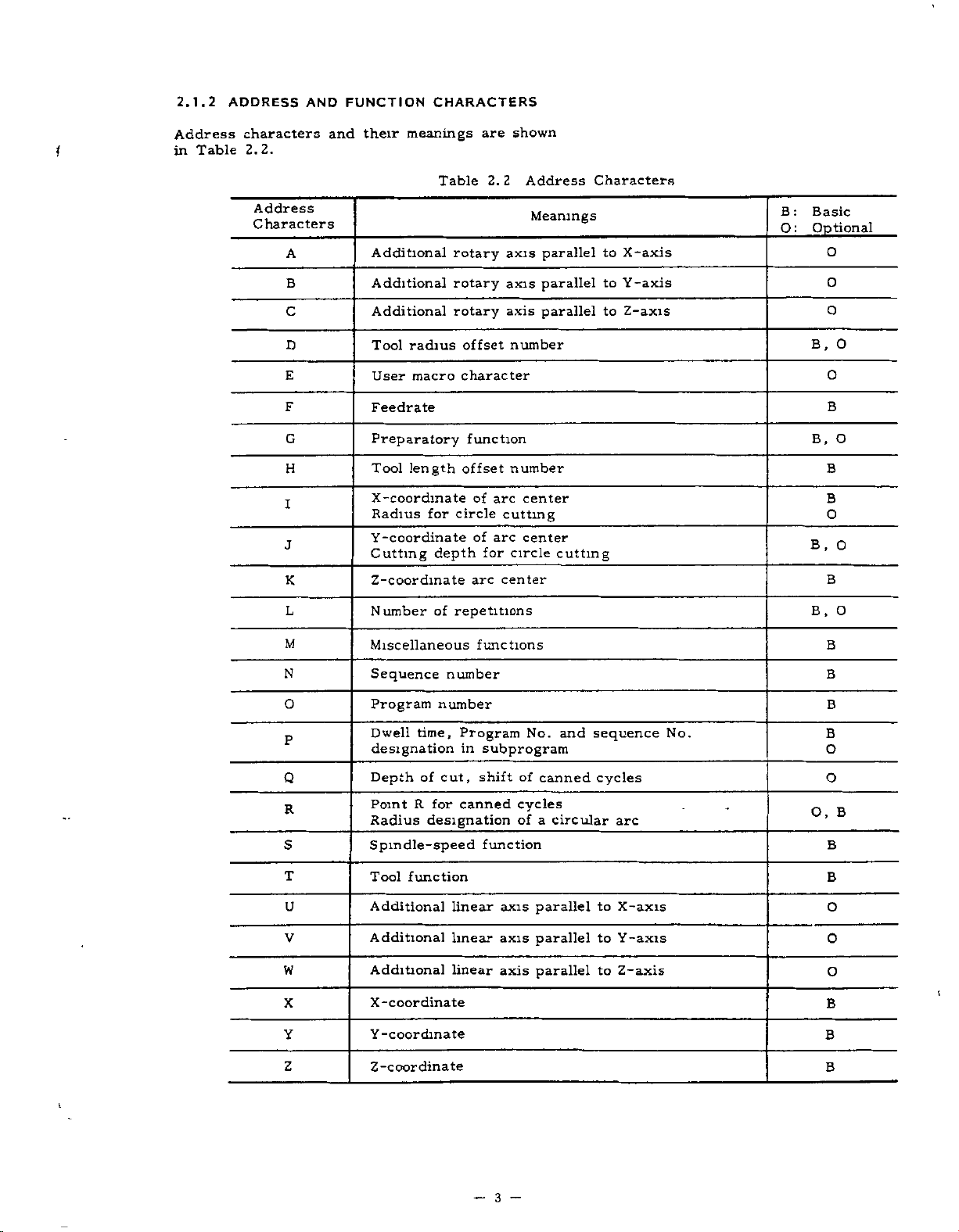
FUNCTION
AND
and
their
CHARACTERS
meanings
are
shown
Table
ADDRESS
characters
2.2.
2.1.2
Address
1
in
Address
Characters
A
B
C
D
E
F
G
H
I
J
K
L
Additional
Additional
Additional
Tool
radius
macro
User
Feedrate
Preparatory
Tool
length
X-coordinate
Radius
for
Y-coordinate
Cutting
depth
Z-coordinate
Number
of
Table
rotary
rotary
rotary
offset
character
function
offset
circle
repetitions
of
of
arc
2.2
for
axis
axis
axis
number
number
arc
cutting
arc
circle
center
Address
Meanings
parallel
parallel
parallel
center
center
cutting
Characters
to
X-axis
Y-axis
to
Z-axis
to
B:
O:
Basic
Optional
O
O
O
B,
0
O
B
B,
O
B
B
O
O
B.
B
O
B.
M
N
O
P
Q
R
S
T
U
V
W
X
Y
Z
Miscellaneous
Sequence
Program
Dwell
time,
designation
Depth
Point
Radius
of
R
designation
Spindle-speed
Tool
function
Additional
Additional
Additional
X-coordinate
Y-coordinate
Z-coordinate
number
number
Program
in
cut,
canned
for
linear
linear
linear
functions
No.
subprogram
shift
of
cycles
of
function
axis
axis
axis
and
canned
a
circular
parallel
parallel
parallel
sequence
cycles
arc
to
X-axis
Y-axis
to
to
Z-axis
No.
O,
B
B
B
B
O
O
B
B
B
O
O
O
B
B
B
1
l
3
-
Page 12

2.1.2
ADDRESS
AND
FUNCTION
CHARACTERS
(CONT
'D)
EIA
Code
Blank
BS
Tab
CR
SP
ER-
UC
LC
2-4-5
bits
2-4-7
bits
+ +
ISO
LF/NL
Nul
BS
HT
CR
SP
Code
%
(
)
Table
Error
2.3
in
Disregarded
Disregarded
Disregarded
End
of
Block
Disregarded
Space
Rewind
Upper
Lower
Control
Control
stop
shift
shift
out
in
Disregarded,
Function
Meanings
significant
in
ISO
(EOB)-
(Comment
(Comment
User
Characters
data
start)
end)
macro
area
in
operator
Remarks
EIA
EIA:
Special
code
0
to
9
z
to
a
/
Del
Parameter
setting
* *
[
]
O
$
@
0
A
DEL
Minus
to
9
to
Z
/
Numerals
Address
Optional
sign,
characters,
block
Disregarded
Decimal
#
Sharp
Astnsk
Equal
[
]
:
$
Left
Right
User
User
User
point
(Variable)
(Multiplication
mark
bracket
bracket
macro
macro
macro
operator
operator
User
skip
(Including
operator
macro
operator
User
All
operator)
macro
Mark)
operator
EIA:
Special
code
Notes:
1.
2.
3.
?
Characters
Information
code
Tape
?
other
between
(EIA
or
than
ISO)
User
the
Control
can
macro
above
Out
be
operator
cause
and
switched
error
Control
by
m
significant
In
setting.
4
is
ignored
area.
data
as
insignificant
data.
Page 13

2.1.3
DECIMAL
Numerals
the
as
dimensional
coordinates
Decimal
dress
points
words.
Coordinate
V,
W,
word:
rate
U,
Time
Feed
EXAMPLE
X15.
containing
(distance),
can
words
Q,
R
P
word:
X15.
POINT
data
be
•
X,
F
mm]
[
000
PROGRAMMING
a
decimal
of
addresses
and
time
used
in
I,
Y,
Z,
mm
or
point
speed.
the
following
K,
J,
[
inch
X15.0000
may
related
A,
be
B,
]
inches
used
to
ad¬
C,
2.1.5
During
read
made
blocks
in
for
contain
2.1.6
For
between
BUFFER
normal
advance
in
the
for
the
In
of
advance
next
the
up
MULTI-ACTIVE
portion
the
M93
follow-on
tool
data
and
operation
to
and
readmadvance.
REGISTER
operation,
and
compensation
radius
or
up
to
compensation
compensation
characters
128
of
part
M92,
of
block
one
computing
operation
.
C+
4
blocks
data
of
computing
is
executed.
One
including
REGISTERS’1-
4
blocks
sandwiched
programs
to
up
data
mode,
are
required
block
EOB.
of
data
is
is
two
read
can
in
are
5
Y20.
(G94)F25.6
G04P1.
Normally,
inputted,
(or
0.0001
parameter
regard
to
parameter
the
LABEL
cases
2.1.4
In
becomes
CRT.
When
When
-
While
the
on
the
punched
neglected.
MEM
the
dicates
of
end
the
—
when
the
inches,
setting,
as
"1"
named
effective,
power
the
RESET
the
label
When
(memory)
the
presence
part
Y
20.
F25.0
(for
Dwell
data
control
1
mm
#601
SKIP
skip
tape
program
500
mm/min
F4.
1.000
without
regards
0.001
or
the
(or
9d6)
•
FUNCTION
below,
and
supply
key
function
up
is
LSK
or
EDIT
of
mm
0)
sec
control
1
inch
the
LSK
is
is
pushed.
to
displayed
pointer
a
.
Y20.5000
or
F25.6
or
(for
a
decimal
"l"
deg.),
may
or
label
displayed
is
turned
effective,
is
the
first
(editing)
as
1
at
F3.1)
but
be
deg.).
skip
on.
EOB
on
the
inches
inches/min
point
0.001
mm
with
made
to
Refer
function
the
on
all
code
CRT
the
mode,
it
leading
is
a
data
are
in¬
M
code
M92
M93
Note:
reset,
marked
When
the
with
Inter-block
of
of
is
always
mode.
is
advance
data.
reading
program
time
processing
blocks
NOTE-
Advance
but
M93
In
Multi-active
Multi-active
power
control
stoppage
made
so
reading
timeofadvance
is
ready
is
that
not
to
is
in
can
be
Meaning
applied
the
be
the
4
of
reading
made
made
register
register
or
the
state
eliminated
automatic
blocks
for
every
to
up
off
on
of
M
operation
is
longer
of
next
4
control
code
when
4
blocks
blocks
is
the
than
4
in
I
5
Page 14

2.2
2.2.1
PROGRAM
PROGRAM
NUMBER
NUMBER
AND
SEQUENCE
NUMBER
When
to
search
hand.
searching
or
for
specify
sequence
program
numbers,
numbers
be
sure
before¬
Program
for
the
to
Up
character
program
trol,
employing
One
program
ends
with
placed
placed
%
<
PROGRAM
PROGRAM
(or
ER
the
top
NOTES:.
•
The
/M02;,
of
programs.
•
make
To
effective
succeeding
program
change.
2.2.2
Integers
ten
following
numbers
Sequence
blocks,
meaning
Therefore,
tial,
and
any
sequence
sequential
numbers.
numbers
purpose
4
digits
11
0"
numbers
and
up
an
M02,
the
at
the
at
010;
.....
ISO
%
at
and
blocks
/M30;,/M99;
the
as
ends
may
of
program
be
may
as
program
can
to
199or999
option.
begins
ends
ends
WITH
NO.
end
for
with
M30
or
of
of
M02; M99;
10
code)
the
of
optional
reading
a
program
(EIA)
ER
is
possible
(#6021po>
an
NUMBER
of
address
SEQUENCE
consisting
.
numbers
and
do.
and
they
duplicated
numbers
are
not
have
sequence
may
number
be
numbers,
are
be
prefixed
identification.
written
numbers.
be
registered
can
a
program
M99.
main
M02
programs,
subprograms.
01234;
77-
PROGRAM
PROGRAM
is
punched
program.
block
are
of
or
up
character
reference
any
of
sequential,
is
also
convenient
regarded
not
M02,
M30,
end,
and
(ISO)
%
with
4
to
digits
influence
machining
and
possible.
to
after
be
registered
number,
and
WITH
NO.
on
such
skip
and
to
as
a
parameter
may
N
numbers
processes.
non-sequen-
also
as
programs
address
an
to
Up
in
the
M30
are
and
M99
1234
the
tape
as
as
M99
the
make
a
sign
be
as
sequence
for
the
on
not
using
Generally,
sequence
99
con¬
and
%
ends
in¬
of
writ¬
NOTES:
•
•
•
is
2.2.3
Those
ed
block,
switch
EXAMPLE
at
When
neglected,
blockisread
With
NOTES-
•
•
While
•
The
5
When
number,
trailing
When
two
number,
no
more
Blocks
searched
contained
OPTIONAL
blocks
are
neglected
when
for
/2
N
the
N
"1",
The
optional
while
the
ter.
If
switching
reading
function
optional
more
or
only
end
or
only
searching
without
for
in
in
the
that
1234
switch
and
as
1234
"1"
may
blocks
the
blocks
on
is
ineffective.
digits
the
effective.
are
more
one
sequence
with
the
BLOCK
which
between
external
number
G01
for
when
if
G01
be
block
is
ineffective
or
block
are
digits
blocks
is
retrieved
performed.
is
respect
blocks.
n/n"
"n"
X100
is
12
the
X100,.
omitted.
skipping
are
read
have
punching
skip
written
up
have
numbers
to
SKIP
(n
In
and
optional
is
13
on,
switch
into
been
to
out
2
/
-
the
to
the
and
the
(/I
1
=
on.
Y200;
the
for
process
the
read,
skip
programs,
/9
as
4th
same
can
address
-
9)
-
the
block
entire
13
buffer
the
is
an
a
sequence
from
sequence
read,
and
also
data
+
/9)
includ¬
is
end
that
of
skip
block
on,
is
executed
is
resis-
subsequent
blocks.
this
option
the
be
is
this
function.
2.3
COORDINATE
Generally,
tions
and
are
tems
words
axes
consist
and
commands
called
numerals
WORD
commands
coordinate
of
address
for
movements
for
setting
words,
characters
representing
in
coordinate
coordinate
and
for
dimensions
axis
sys¬
desired
direc¬
of
directions.
6
-
Page 15

2.3.1
COORDINATE
WORD
Table
2.4
Coordinate
Words
!
Main
4th
axesL
Circular
interpolation
auxiliary
data
2.3.2
OF
Table
axes
SIMULTANEOUS
THREE-AXIS
5
2.
.
Table
2.5
shows
Simultaneously
Three-axis
Address
axes
and
5th
CONTROL
CONTROLLABLE
simultaneously
Control
Y,
X.
B,
A,
or
V,
U,
Q
R
I,
J,
controllable
Controllable
the
B
V
and
and
or
coordinate
directions
C
W
arc
GI3)
Z
C
W
Position
direction.
These
in
A,
U,
Circular
(
G1Z
Generally,
K
Generally,
center
AXES
(in
2.3.3
OF
Table
axes
of
Axes
Simultaneously
axes
axes
XY,
(see
X
and
direction.
control
axes
or
YZ
Note.
Y
and
HELICAL
.
of
ZX
)
linear
Positioning
Linear
tion
Circular
polation
Circular
G12,
Helical
tion
X,Y
Manual
controllable
,
Y
X
Y
X,
Two
Two
Circle
feed
Refer
INTERPOLATION
Simultaneous
and
interpola¬
inter¬
G02,
cutting4'
interpola¬
G02,
G03
control
GOO
G03
Positioning
i
Linear
tion
Circular
G01
polation
Circle
,
G13
G
12
Helical
tionÿ
Manual
and
and
axes
axes:
in
in
to
Z
Z
Z
:
XY-plane
Z-axis
2.9.5
Description
distance
words
of
used
are
used
are
increment
_
radius
distances
X,
and
Y
SIMULTANEOUSLY
FOUR-AXIS
2.
.
interpola¬
G01
G13
interpola¬
t
G02
2.6
control
Table
,
in
X
are
the
4th
for
rotary
parallel
for
in
values
6
of
from
Z
components).
shows
Simultaneously
GOO
inter¬
G02,
GO
cutting?
,
3
GO
treated
and
coordinate
5Th
motion,
motion.
cutting
YorZ
circle
circles.
start
point
CONTROL+
simultaneously
Four-axis
3
X,
Y
Y,
X,
Two
Xa1’
Two
axes:
Three
plane
direction.
axis
2.9.5
LATION
One
Control
controllable
,
axes
Yaa|
and
axis,
commands
as
axes.
and
arc
to
CONTROLLABLE
controllable
Controllable
Simultaneously
axes
,
Z
Z,
axes:
HELICAL
aa>
and
coaxes
and
mp}
,
XY,
ZaaJ
or
and
X
circle
linear
on
page
X,
Y,
axes
YZ,
feed
Refer
INTERPO¬
27.
Z,
Y
Axes
ZX,
in
in
or
AXES
of
XY-
Z-
tc
of1!
Note:
Circular
currently
(G17
to
details,
For
POLATION
arc
effective
G19)
plane
refer
(G02,
determined
is
codes
G
2.9.4
to
G03)
on
for
plane
CIRCULAR
24.
page
according
designation.
INTER¬
(I)The
U,
the
to
(2)
Circular
the
nation
on
(3)
For
linear
2.9.4
axis
d
or
V
currently
(G17
CIRCULAR
page
circular
axes
represents
W,
selected
arc
plane
to
24.
interpolation
U,
any
as
is
effective
G19)
determined
G
For
.
INTERPOLATION
andWshould
V,
oneofaxes
the
4th
codes
details,
axis
for
a,
be
axis.
according
plane
refer
any
designated.
(G02,
one
A,
B,
desig¬
to
G03)
of
C,
to
i
7
—
Page 16
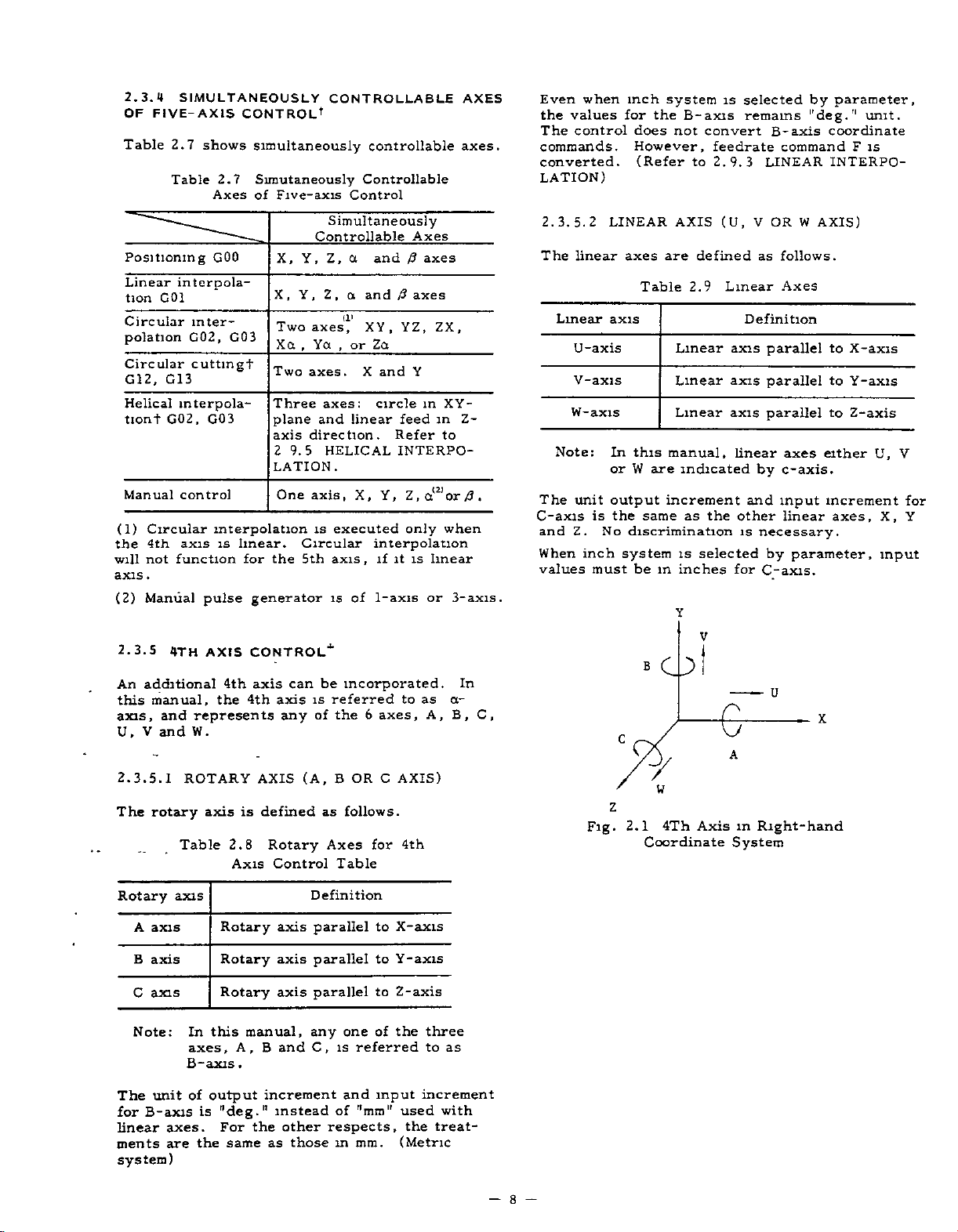
2.3.4
OF
FIVE-AXIS
Table
Positioning
Linear
tion
Circular
polation
Circular
G12,
Helical
tiont
Manual
(1)
Circular
4th
the
not
will
.
axis
(2)
Manual
SIMULTANEOUSLY
CONTROL1
2.7
shows
2.7
Table
Axes
GOO
interpola¬
G01
inter¬
G03
G02,
cuttingf
G13
mterpola-
G02,
G03
control
interpolation
is
pulse
linear.
for
axis
function
CONTROLLABLE
simultaneously
Simutaneously
of
Five-axis
Simultaneously
Controllable
X,
Y,
Z,
X,
Y,
Z,
Two
axes,
Xa,Ya
Two
axes.
Three
plane
axis
2
LATION.
the
generator
9.5
One
axes:
and
direction.
HELICAL
axis,
is
Circular
5th
axis
is
controllable
Controllable
Control
a
and
and
a
(!'
XY,
,
Za
or
X
circle
linear
X,
executed
interpolation
,
if
1-axis
of
Axes
/?
axes
J3
YZ,
and
Y
feed
Refer
INTERPO¬
Z,a(2,or/J.
Y,
only
is
it
axes
in
linear
or
ZX,
XY-
in
to
when
AXES
axes.
Z-
3-axis.
when
Even
the
values
The
control
commands.
converted.
LATION)
2.
The
3.
2
5.
linear
Linear
U-axis
V-axis
W-axis
Note:
The
unit
C-axis
and
When
values
is
Z.
inch
must
inch
for
does
However,
(Refer
LINEAR
axes
Table
axis
this
In
or
W
output
the
same
No
discrimination
system
be
system
the
B-axis
not
AXIS
are
2.9
Linear
Linear
Linear
manual,
are
indicated
increment
as
is
in
inches
is
convert
feedrate
to
2.9.3
(U,
defined
Linear
the
selected
selected
remains
LINEAR
V
as
Definition
axis
axis
axis
linear
by
and
other
is
necessary.
for
C-axis.
B-axis
command
OR
W
follows.
Axes
parallel
parallel
parallel
axes
c-axis.
input
linear
by
parameter,
by
parameter,
"deg."
coordinate
INTERPO¬
AXIS)
to
to
to
either
increment
axes,
unit.
F
is
X-axis
Y-axis
Z-axis
U,
X,
input
V
for
Y
2.3.5
An
this
axis,
V
U,
2.3.5.
The
Rotary
A
B
C
Note:
4TH
additional
manual,
and
represents
W.
and
ROTARY
1
rotary
Table
axis
axis
axis
axis
In
axes,
B-axis
AXIS
the
axis
Rotary
Rotary
Rotary
this
4th
is
2.8
Axis
A,
.
CONTROL''
be
can
axis
4th
AXIS
defined
manual,
B
axis
any
Rotary
Control
axis
axis
axis
and
is
of
(A,
as
Definition
parallel
parallel
parallel
any
C,
incorporated.
referred
the
B
OR
6
axes,
C
follows.
for
Axes
Table
to
to
to
of
one
referred
is
as
to
AXIS)
4th
X-axis
Y-axis
Z-axis
the
A,
three
to
V
»
In
a-
C,
B,
O
U
c
W
e
A
X
z
Axis
4Th
2.1
Fig.
Coordinate
as
in
Right-hand
System
The
unit
for
B-axis
linear
ments
system)
axes.
are
of
output
is
the
"deg."
For
same
increment
instead
other
the
as
those
and
of
"mm"
respects,
m
mm.
input
increment
used
the
(Metric
with
treat¬
—
8
Page 17

2.3.6
f
An
this
axis,
U,
5TH
additional
manual,
represents
and
W.
and
V
the
5th
axis
5th
can
axis
any
be
incorporated.
is
referred
the
of
6
to
axes.
as
In
0-
C,
B,
A,
CONTROLÿ
AXIS
The
C-axis
and
When
values
unit
Z.
inch
output
the
is
No
discrimination
system
must
increment
as
same
is
beininches
selected
the
and
other
necessary.
is
for
C-axis.
input
linear
by
increment
axes,
parameter,
X,
input
for
Y
2.3.6.
The
1
rotary
Rotary
axis
A
axis
B
C
axis
Note:
unit
The
b-axis
for
linear
ments
axes.
are
system)
Even
when
the
values
The
control
commands.
converted.
LATION
ROTARY
axis
Table
axis
this
In
,
axes
b-axis.
of
output
Mdeg.''
is
For
same
the
inch
for
does
However,
(Refer
page
on
is
2.10
5th
Rotary
Rotary
Rotary
manual,
A,B
system
the
not
AXIS
defined
Axis
and
increment
instead
the
other
as
b-axis
convert
to
24.)
(A,
B
as
Rotary
Control
Definition
axis
axis
axis
any
,
C
respects,
in
those
selected
is
remains
feedrate
3
9.
2.
OR
follows.
Axes
parallel
parallel
parallel
one
referred
is
and
of
"mm"
mm.
b-axis
command
LINEAR
C
of
input
by
"deg."
AXIS)
for
the
used
(Metric
to
X-axis
Y-axis
to
to
Z-axis
three
to
as
increment
with
the
treat¬
parameter,
unit.
coordinate
is
F
INTERPO¬
2.3.7
OUTPUT
2.
7.1
3.
The
minimum
punched
by
2.12.
Metric
c
z
Fig.
LEAST
INCREMENT
LEAST
Table
input
B
o
W
2.2
Coordinate
INPUT
INPUT
input
tape
2.12
(#6006D5
5ThAxis
INCREMENT
units
MDI
or
Least
Linear
0.
001
U
e
A
in
Right-hand
System
INCREMENT
that
can
shown
are
=
mm
Increment
“O.")
Axis
Input
X
-
AND
be
commanded
Table
in
Rotary
0.
001
LEAST
Axis-*-
deg
2.
The
3.
6.
linear
Linear
U-axis
V-axis
W-axis
Note:
2
LINEAR
axes
Table
axis
this
In
W
or
AXIS
are
2.11
5th
Linear
Linear
Linear
manual,
are
(U,
defined
Linear
Axis
Control
Definition
axis
axis
axis
indicated
V
as
parallel
parallel
linear
by
OR
follows.
Axes
parallel
axes
c-axis.
W
AXIS)
for
to
to
to
either
X-axis
Y-axis
Z-axis
U,
0.
001
be
001
0.
0.001
set
deg
by
Axisÿ
deg
deg
by
Inch
Least
setting
Metric
Inch
Metric
setting
input
input
parameter
input
input
input
#6001D0.
increment
Input
(#6006D5
inch
and
0.0001
times
#6006D5
Increment
=
Linear
0.
001
0.001
input
Axis
mm
in.
in
at
"1.")
can
ten
"1."
x
can
10
be
Rotary
selected
V
9
—
Page 18

2.3.
7.1
Notes
:
•
Selection
made
•
Selection
eter
setting
Tool
offset
(or
mm
is
possible
In
0.01
eration
Programming
•
Write
•
Programming
•
Program
LEAST
of
by
setting
of
value
0.0001
in
mm
increment
must
operation
editing
INPUT
metric
x
1
(#6006D5).
must
inch,
these
be
made
for
in
for
INCREMENT
system
(#6001D0).
10
or
x
always
0.001
or
units.
system,
in
the
operation
MDI
operation
operation
is
unit
mode.
in
inch
or
made
be
degt
the
in
MEMORY
in
EDT
by
written
following
of
TAPE
(CONT'D)
system
param¬
in
)
,
and
0.01
mm.
mode.
modet.
mode"1'.
is
0.001
offset
op¬
incremental
In
not
exceed
absolute
In
must
axis
value
Note:
move
a
value
mable
dresses
mand
The
accumulative
accumulative
mum
the
programming,
not
.
machine
The
command
is
given.
values
J,
I,
addresses
Table
programming,
maximum
exceed
over
The
also
K,
R,
X,
2.15
Linear
the
may
the
above
apply
value
to
in
Q
Z,
Y,
must
values
Maximum
input
programmable
move
amount
maximum
not
maximum
maximum
programmable
function
distance
addition
a.
shown
not
to
exceed
below.
Cumlative
axis
values
must
value.
of
each
properly
programmable
program¬
command
move
the
ad¬
com¬
maxi¬
Values
Rotary
axis'!"
if
NOTES:
•
NC
If
or
to
increment,
the
•
the
If
contents
machine
the
When
-
tape-1-,
stored"
ment
3.
2.
7.
Least
motion.
by
parameter
Metric
Inch
2.3.8
Maximum
are
mand
Table
programmed
tape
stored
in
the
intended
increment
of
NC
move
will
commanded
the
stored
the
stored
regardless
system.
2
LEAST
output
increment
Selection
(#60Q7D3)
Table
output
MAXIMUM
2.13
output
programmable
shown
Maximum
2.14
an
equipment
machine
will
dimensions.
by
by
are
is
stored
ten
system
tape
dimensions.
program
figures
of
switching
OUTPUT
of
Least
Linear
PROGRAMMABLE
metric
0.001
0.
0001
INCREMENT
the
is
setting.
Output
axis
mm
in.
dimensions
below.
Programmable
0.001
set
move
switched
times
punched
is
are
minimum
or
inch
Increment
is
mm
0.01
by
times
ten
when
in
memory,
one
or
out
punched
of
the
unit
output
Rotary
001
0.
0.
001
DIMENSIONS
of
move
Dimensions
fed
tenth
out
incre¬
is
axis'!-
deg
deg
com¬
mm
the
on
of
in¬
the
of
the
"as
tool
made
Metric
Inch
input
Listed
inch
output
2.4
TRAVERSE
2.4.1
1
2.4.1.
The
rapid
for
the
the
Manual
erse
rates
dependent
determined
rapid
traverse
set
are
axes.
in
motions
of
two
each
or
different
motion
For
and
paths
override
100%
available.
parameter
2.4.1.2
RATE
input
input
AND
RAPID
RAPID
traverse
Positioning
Rapid
differ
on
by
by
parameters
the
When
three
in
these
other,
times
are
rapid
of
the
Fo
(#6231).
SETTING
±
99999.999
±
9999.9999
values
system.
FEED
TRAVERSE
TRAVERSE
motion
(GOO)
Traverse
among
the
machine
the
machine
rates
tool
axial
axial
and
the
among
normally
traverse
basic
a
is
constant
RANGE
mm
in.
do
not
depend
FUNCTIONS
RATE
RATE
is
and
(RAPID).
the
axes
specification
tool
determined
in
advance
is
moved
directions
directions
end
points
these
motions.
not
rates,
rapid
traverse
feed
OF
±
99999.999
±
99999.999
on
used
for
the
for
motion
since
builders.
the
by
for
in
individual
rapid
simultaneously,
are
independent
are
reached
Therefore,
straight.
Fo,
rates,
rate
set
RAPID
TRAVERSE
metric/
the
motion
The
they
and
The
machine
traverse
25%,
by
deg
deg
for
trav¬
are
are
at
50%
are
a
Metric
output
Inch
output
Metric
Inch
Metric
Inch
input
input
input
input
Linear
±8388.
axis
607
±330.2601
±21307.062
8607
±838.
mm
in.
mm
in.
Rotary
±8388.607
±8388.607
±8388.607
±8388.
607
axis+
deg
deg
deg
deg
—
10
For
each
at
some
min)
.
The
24,000
is
tools
Refer
builder.
-
suitable
maximum
have
to
axis,
programmable
mm/min.
their
the
manual
rapid
multiple
own
traverse
However,
optimum
provided
of
rates
7.5
mm/min
rapid
respective
rapid
by
can
traverse
traverse
the
be
(or
machine
machine
set
deg/
rate
rates.
tool
Page 19

2.4.2
five
With
feedrates
tool
med.
The
programmable
FEEDRATE
digits
per
FUNCTION)
(F
following
minute
range
address
an
(mm/tnin)
of
feedrates
character
are
program¬
as
is
F,
follows
G03
With
F
=
(mm/min)
X
this
200
Y
----
command,
----
=7fX2
+
I
F200
;
----
FY2
Table
Metric
output
Inch
output
The
ance
When
machine
mable
a
parameter
above
feedrate
commands
F
involving
{
two
tion
EXAMPLE
maximum
the
of
the
feedrate
the
axial
tangential
G01
this
With
500
F
=
(mm
/
2.16
Metric
Inch
Metric
Inch
servo
maximum
system
(#6228),
set
is
clamped
for
motions
directions
G91
X40.
command,
=
J
min)
feedrate
maximum
Programmable
Format
input
input
input
input
is
given
linear
to
(incremental)
Y30.
3002
F40
F31
F50
F31
system
feedrate
below
above
and
at
and
simultaneously
in
specify
motion
the
+
4002
is
the
limit
the
F500
subject
and
Range
Feedrate
FI.-
F0.1
FI.-
F0.1
set
maximum
,
the
whenever
are
set
circular
feedrates
path.
;
Y
component
of
(Feed/mm)
F8100.
F313.0
-
F20574.
810.0
-
the
to
the
machine
the
by
former
feedrates
commanded,
maximum
interpolations
controlled
X
component
Feedrate
mm/min
in.
/min
mm/min
min
in.
/
perform¬
system.
servo
program¬
set
is
value.
the
in
range
or
by
the
direc¬
commands
F
motions
directions
tangential
EXAMPLE
With
F
=
(mm
CENTER
fX
for
in
simultaneously
specify
the
to
X-*-
G01
400
=
,/fX2
/min)
/
/
t
linear
motion
+Y
START
POINT
200
I
z
+
Fig.
interpolations
feedrates
Y...
+
f
END
—
mm/mm
2.4
controlled
path.
Z---
2
Y
POINT
V7
\
fz
also
+
fz2
400nrai/min
(«
in
F400
+X
involving
three
the
direction
;
axial
y
+z
Fig.
300
mm/
X
+
400
mm/min
2.2
Fig.
t
mm
commands
F
motions
directions
tangential
(mm/min)
F
11
—
-
for
in
simultaneously
specify
the
to
linear
feedrates
motion
=
2.5
interpolations
controlled
also
path.
+
+
fY2
in
fz2
involving
four
direction
the
+
fa2
axial
Page 20

2.4.2
NOTES:
•
FO
If
error.
•
Do
not
otherwise
EXAMPLE
F-250
2.4.3
feedrate
The
converted
as
ting
When
•
the
Metric
output
Inch
output
•
When
feedrate
the
2.4.4
(1)
Specification
selects
F
FEEDRATE
is
programmed,
(alarm
program
correct
;
FEEDRATE
programmed
to
1
follows.
parameter
feedrates
Table
F
2.17
Metric
Inch
Metnc
Inch
input
parameter
1-DIGIT
the
corresponding
input
(F
FUNCTION
is
it
code
F
commands
operation
"030)
regarded
wrong
1/10
F
/10-th
#6020
range
by
with
value
or
DO
becomesasshown
Programmable
1/10
Feedrate
Format
input
input
#6020
range
F41
F32
F51
F32
returns
Feedrate
F1.0-F8100.0
F0.01
F1.0-
01
F0.
DO
or
to
PROCRAMMINCT
of
a
value
1
preset
){
CONT'D)
minus
with
is
not
commands
a
parameter
is
D1
Range
(Feed/nun)
mm
-
313.00
F
F20574.0
F810.
-
D1
is
normal.
to
9
that
feedrate.
as
data
a
numerals,
guaranteed.
can
set
"1,"
to
below.
of
range
/mm
in.
/min
mm/min
00
/nun
in.
set
"0,"
to
follows
be
set¬
Table
F
Setting
Table
command
F
2.18(a)
command
FI
F2
F3
4
F
F5
F6
F7
F8
F9
"l"
2.18(b)
Parameter
FI
F2
F3
F4
F5
F6
F7
F8
F9
Setting
=0.1
F
Parameter
Fl-digit
F
Command
No.
Setting
Fl-digit
mm/nun
Command
No.
#6141
#6142
#6143
#6144
#6145
#6146
#6147
#6148
#6149
No.
#6561
#6562
#6563
#6564
#6565
#6566
#6567
#6568
#6569
No.
multiply
and
for
speed
and
for
(2)
Set
setting
(3)
By
when
Fl-DIGIT
command
digit
creased
crement
parameters
result
As
a
setting
changed.
(4)
Upper
the
Set
to
the
the
than
#6228)
of
of
#6228.
the
number
operating
or
decreased.
value
listed
of
number
Limit
maximum
following
usual
is
feedrate
shown
switch
currently
per
in
this
of
of
feedrate
parameter.
maximum
set,
it
of
in
the
manual
is
Set
pulse
Table
operation
the
Fl-digit
Feedrate
is
governed
each
of
Table
pulse
the
on,
specified
the
(Fl-digit
2.18(b).
,
the
of
Fl-digit
If
feedrate
to
FI
2.18(a).
generator
feedrate
may
increment
multiply)
contents
feedrate
a
value
(the
the
by
to
F9
the
of
axe
in¬
or
FI¬
de¬
to
the
of
be
designation
greater
contents
contents
the
—
12
—
Setting
Table
Parameter
#6226
#6227
NOTES:
a.
When
9
to
I
lowed.
usually
b.
If
c.
When
run
is
d.
For
ride
feature
The
e.
after
the
"l"
2.18(c)
Maximum
No.
this
mm/mm
Specifying
.
F0
is
DRY
assumed.
Fl-digit
feedrate
power
0.1
=
Max
Max
feature
the
by
specified,
RUN
specification,
invalid.
is
stored
is
/nun
nun
Parameter
Feedrate
Meaning
speed
speed
installed,
is
usual
10
mm/roin
error
switch
in
off.
turned
/pulse
of
FI
of
F5
F
function
or
"030"
on,
is
the
memory
No.
F4
to
to
F9
the
more
will
the
feedrate
is
for
specifying
is
not
allowed
is
be
caused.
of
rate
retained
al¬
dry
over¬
Page 21

2.4.5
AUTOMATIC
DECELERATION
Acceleration
cutting
and
5.1
2.4.
OF
RAPID
the
In
matic
•
Positioning
Manual
-
•
Manual
•
Manual
feed
ACCELERATION
TRAVERSE
following
acceleration
rapid
continuous
HANDLE
and
deceleration
are
operation,
(GOO)
traverse
ACCELERATION
for
automatically
AND
MANUAL
AND
the
deceleration
and
(RAPID)
feeding
feeding
(JOG)
(HANDLE)
AND
rapid
traverse
performed.
DECELERATION
FEED
of
pattern
is
auto¬
linear.
SPINDLE-SPEED
2.5
2.5.1
The
lowing
For
speed
S
spindle
the
each
(rpm)
manual.
a
a
block,
move
When
in
together
completion
builder
tool
manual
.
2-DICIT
speed
address
code
S
,
command
whether
with
of
FUNCTION
PROGRAMMING
is
S
and
refer
to
the
the
move
move
tool
Refer
to
(S-FUNCTION)
specified
(S00
to
its
corresponding
the
machine
and
an
S
command
command
depends
the
machine
by
S99).
S
code
or
on
two
tool
is
after
the
tool
digits
spindle
builder's
are
issued
executed
the
machine
builder's
fol¬
V
coo
i
e
t—
•
§
>
TIME
2.
to
3)
and
are
6
acceleration
can
rate
#6301)
/DECELERATION
deceleration
and
the
in
Fig.
rapid
(#6280
acceleration
(G01
F,
rate
-
traverse
GO
Rapid
constant
traverse
of
parameter.
2
ACCELERATION
5.
{
2.4.
FEEDRATE
•
Automatic
motion
V
t
/deceleration
be
set
exponential
by
of
OF
feed
mode.
EXAMPLE
GOO
Sll
X
Z
G01
GOO
X---
X-Y
Z
1
GO
S2Z
X.
NOTE
machine
M03
.
•
S
command
Spindle
Y
F
Y
F
.
Y
The
two-digit
whenSand
z-
Z
Z
F
CW
M05
M03
:
BCD
two-digit
Sll
,
•
,
Sll
S22
!
output
command
Effective
Spindle
Effective
Effective
is
sent
is
stop
to
issued
the
E
O
•
Feedrate
vals
by
Note*
The
eters
spective
unless
>
2.7
Fig.
time
feedrate
and
parameters.
automatic
are
set
machines.
this
is
Exponential
deceleration
constants
(#6092,
acceleration
to
the
optimum
Do
required
TIME
bias
/deceleration
not
for
special
are
set
is
#6093)
values
change
acceleration
set
at
for
the
purposes.
4
at
2kpps
param¬
re¬
the
setting
t
msec
intervals
inter¬
i
13
-
-
Page 22
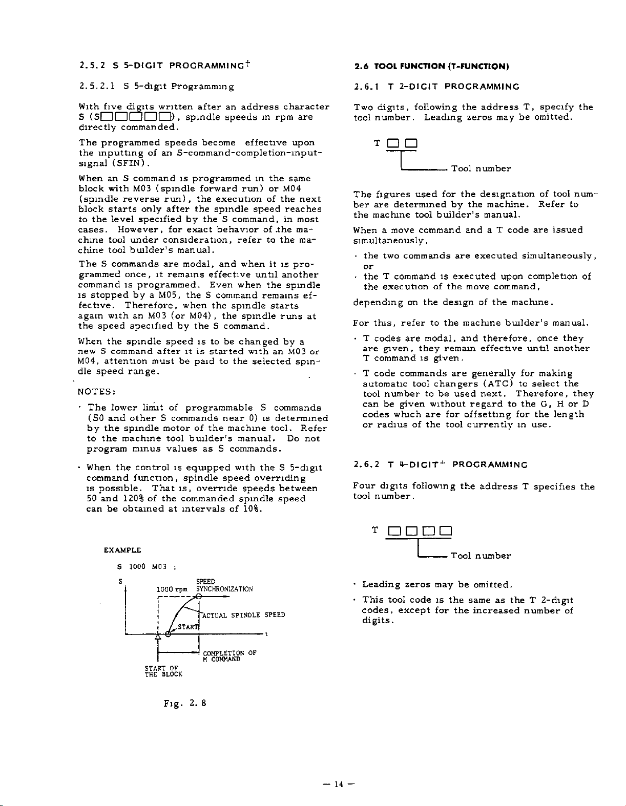
2.5.2
S
5-DIGIT
PROGRAMMING*
2.6
TOOL
FUNCTION
(T-FUNCTSON)
5.
2.1
2.
five
With
(
S
S
I
directly
The
programmed
the
inputting
signal
When
block
(spindle
block
the
to
cases.
chine
chine
The
S
grammed
command
is
stopped
fective.
again
the
speed
the
When
S
new
M04,
attention
dle
speed
NOTES:
•
The
(SO
the
by
the
to
program
•
When
command
is
possible.
50
and
be
can
S
5-digit
digits
111
written
1
1
1 1
1
commanded.
of
(SFIN)
S
an
with
reverse
starts
level
However,
tool
tool
under
builder's
an
.
command
M03
(spindle
only
specified
commands
once,
is
Therefore,
with
it
programmed.
a
M05,
by
M03
an
specified
spindle
command
after
must
range.
lower
and
limit
otherScommands
spindle
motor
machine
minus
the
control
function,
That
the
of
120%
obtained
Programming
I)
.
spindle
speeds
after
become
address
an
speeds
effective
in
S-command-completion-input-
is
programmed
forward
run)
,
the
the
after
the
by
for
exact
consideration,
execution
spindle
S
behavior
in
run)
speed
command,
of
refer
or
of
to
manual.
modal,
are
remains
theScommand
when
(or
by
speed
it
be
of
programmable
tool
values
equipped
is
spindle
is,
commanded
intervals
at
effective
Even
the
M04)
,
the
S
to
is
is
started
paid
the
of
builder's
as
override
and
when
when
spindle
the
spindle
command.
be
changed
the
to
near
machine
manual.
S
commands.
with
speed
speeds
spindle
of
10%.
it
until
the
remains
with
selected
S
0)
is
the
overriding
character
are
rpm
upon
the
same
M04
the
next
reaches
most
in
.the
ma¬
the
ma¬
is
pro¬
another
spindle
ef¬
starts
runs
by
a
MQ3
an
spin¬
commands
determined
tool.
Refer
Do
S
5-digit
between
speed
at
not
2.6.1
Two
tool
T
digits,
number.
2-DICIT
following
Leading
PROCRAMMING
the
address
zeros
may
T,
be
specify
omitted.
the
T
Tool
The
ber
the
When
figures
determined
are
machine
move
a
for
used
builder's
tool
command
-
by
number
the
designation
the
and
machine.
manual.
T
code
a
of
Refer
are
tool
to
issued
num¬
simultaneously,
•
the
or
•
the
the
depending
For
•
T
or
are
T
•
T
automatic
tool
can
codes
or
2.6.2
Four
tool
commands
two
T
commandisexecuted
execution
the
on
this,
refer
codes
given
command
code
modal,
are
,
they
is
commands
tool
number
be
given
which
T
4-DICIT"
of
following
radius
digits
number.
of
the
design
the
to
remain
given.
are
changers
be
used
to
without
for
are
the
tool
PROCRAMMINC
are
executed
move
of
machine
and
generally
regard
offsetting
currently
the
upon
command,
the
builder's
therefore,
effective
(ATC)
next.
address
simultaneously,
completion
machine.
once
until
for
making
select
to
Therefore,
G,
the
to
the
for
use.
in
T
specifies
manual.
they
another
the
they
or
H
length
of
D
the
EXAMPLE
1000
S
s
MO
1000
t
START
THE
3
rpm
A.
OF
BLOCK
Fig
SPEED
SYNCHRONIZATION
'ACTUAL
START
COMPLETION
COMMAND
M
2.8
.
SPINDLE
OF
SPEED
—
14
•
•
—
T
Leading
This
codes,
digits.
tool
zeros
code
except
may
is
for
Tool
the
the
number
be
omitted.
same
increased
as
the
T
2-digit
number
of
Page 23
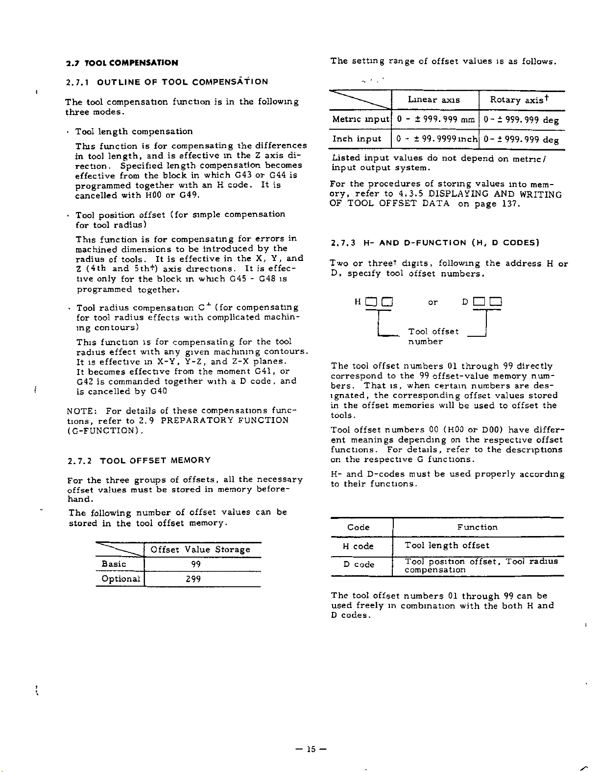
2.7
COMPENSATION
TOOL
The
setting
range
of
offset
values
as
is
follows.
OF
2.7.1
The
three
•
OUTLINE
tool
modes.
length
Tool
This
in
tool
rection.
effective
compensation
compensation
function
length,
Specified
from
programmed
position
tool
function
of
only
with
radius)
dimensions
tools.
and
for
cancelled
Tool
for
This
machined
radius
(4th
Z
tive
programmed
Tool
for
ing
This
radius
is
It
becomes
It
G42
cancelled
is
the
following
radius
radius
tool
contours)
function
effect
effective
is
commanded
For
refer
TOOL
three
values
the
in
effective
details
to
OFFSET
must
•
i
NOTE:
tions,
(G-FUNCTION)
2.7.2
For
offset
hand.
The
stored
TOOL
for
is
and
block
the
together
H00
offset
is
for
It
5th+)
the
block
together.
compensation
effects
for
is
with
X-Y,
in
G40
by
of
PREPARATORY
2.9
.
groups
be
number
tool
offset
COMPENSATION
function
compensating
is
effective
length
compensation
in
an
with
G49.
or
(for
simple
compensating
be
to
effective
is
directions.
axis
in
which
C1
with
compensating
any
given
Y-Z,
the
from
together
these
compensations
MEMORY
offsets,
of
stored
offset
of
memory.
the
is
in
the
the
in
H
G43
code.
which
compensation
for
introduced
the
in
G45-G48
(for
compensating
complicated
for
machining
Z-X
and
moment
D
a
with
FUNCTION
the
all
in
memory
values
following
differences
Z
axis
becomes
or
It
errors
by
X,
is
It
machin¬
the
contours.
planes.
G41,
code,
necessary
before¬
can
G44
is
the
Y,
effec¬
is
tool
or
and
func¬
be
di¬
is
in
and
Metric
Inch
input
Listed
input
For
ory,
OF
2.7.3
Two
D,
The
input
output
the
refer
TOOL
H-
or
specify
H
tool
correspond
bers.
That
ignated,
offset
the
in
tools.
Tool
offset
ent
meanings
functions.
the
on
H-
to
respective
and
their
Code
input
0
0
values
system.
procedures
to
OFFSET
AND
threet
tool
offset
to
is,
the
corresponding
memories
numbers
depending
For
D-codes
functions.
Linear
±
-
999.
±
99.
-
of
4.3.5
DATA
D-FUNCTI
digits,
offset
Tool
number
numbers
the
99
when
details,
G
must
axis
999
mm
inch
9999
do
not
depend
storing
DISPLAYING
on
page
(H,
ON
following
numbers.
or
D
offset
01
through
offset-value
certain
numbers
offset
be
on
refer
used
or
the
to
00
will
(H00
functions.
used
be
properly
Function
Rotary
00-
values
AND
D
the
memory
values
D00)
respective
the
axis"*"
±
999.999
±
999.999
on
metric/
into
WRITING
137.
CODES)
address
99
directly
are
stored
offset
to
have
descriptions
according
deg
deg
mem¬
num¬
des¬
the
differ¬
offset
or
H
•>
Basic
Optional
Offset
Value
99
299
Storage
Tool
H
code
D
code
The
tool
offset
used
freely
D
codes.
-
15
-
in
length
Tool
position
compensation
numbers
combination
01
offset
offset.
through
with
the
Tool
99
both
can
radius
be
and
H
Page 24

2.7.3
H-
AND
D-FUNCT1
ON
(H,
D
CODES)
(CONT'D)
However,
for
edtodivide
code
D
part.
Tool
Tool
Tool
tion
(Intersection
puting
2.8
MISCELLANEOUS
The
miscellaneous
M
M
machine
M
of
M
CODES
(Program
code,
stops
and
code
codes
with
address
each
of
machine,
the
the
to
tion
concerned
2.8.1
•
MOO
This
mode,
commandsmthe
been
completed
program
CYCLE
•
M01
M01
stop
is
the
•
M02
M02
in
on.
automatic
may
START
(Optional
performs
MOO
whenever
When
M01
code
(End-
is
used
of-
programming
the
numbers
Offset
length
position
dia.
compensa¬
C
system)
FUNCTIONS
function
maximum
(MOO
tool
except
the
FOR
for
builder's
control.
STOP
except
Stop)
when
given
the
automatic
block
and
be
continued
button.
Stop)
the
same
the
the
OPTIONAL
is
disregarded.
Program)
end
the
at
operation
method
offset
offset
com¬
three
to
several
for
m
containing
MOO
R
function
OPTIONAL
of
mode,
it
ease,
intoHcode
Table
(M-FUNCTION)
is
specified
digits.
M89)
determined
is
codes.
M
manual
the
following
(MOO,
M01
automatic
operation
signal
by
is
pressing
as
STOP
program.
this
recommend¬
is
part
H
2.19
code
G
G43
G44
G49
G45
G46
G47
G48
G40
G41
G42
with
The
for
the
M
M02,
,
operation
after
have
MOO
fed.
the
program
STOP
switch
When
code
stops
and
D
or
the
function
by
Refer
func¬
codes
M30)
the
The
switch
off,
is
given
Code
H
H
D
or
nrjjT}
[T][T]
NOTES:
•
Refer
H
D
and
D
code
the
the
Although
the
fer
M30
M30
automatic
automatic
block
addition,
and
details
the
to
When
vents
block
fed
is
M
codes.
Whether
dle
refer
Whether
rewinds
by
the
(a)
(b)
codes:
codes:
Offset
HOI
D31
Number
Offset
No
01
02
03
04
\
96
97
98
99
automatic
block
containing
the
details
to
the
are
machine
(End-of-Tape)
is
given
at
operation
operation
containing
most
in
rewinds
are
the
determined
machine
M01,
MOO,
the
control
of
information.
addition
in
MOO,
coolant
stop,
the
to
the
the
machine
control
tape
following
Input
reset
Input
input)
to
the
signal
input)
signal
wired
is
machine
H30
to
to
D99
value
.
Offset
operation
control
determined
tool
the
end
after
M30
cases,
tape
builder's
tool
M02
from
to
M01,
M02
off
(or
state.
the
of
wired
is
of
the
for
tool
memory
value
after
M02
have
reset
is
by
builder’s
of
tape.
mode,
the
been
have
the
(or
memory).
the
by
M30
or
reading
The
the
or
is
single
2-digit
M30
or
some
tool
builder's
automatically
memory
control
for
control
"ON"
builder's
the
been
in
most
the
manual.
this
code
commands
completed.
control
machine,
manual.
is
given,
ahead
BCD
executes
other
)
,
is
"EOP"
"ON"
"RWD"
or
not.
manual.
commands
completed.
cases,
machine.
When
given
stops
in
reset
is
Since
refer
it
pre¬
the
decoded
output
spin¬
executions,
manual.
reset
determined
(internal
not.
or
(rewind
in
Re¬
in
the
the
In
the
next
signal
for
or
16
-
—
Page 25

2.8.2
(M90
M90
cessing.
M
TO
through
external
is
sent.
M90+:
M91+:
M92+:
M93+:
M94:
M95:
M96+:
M97+:
M98:
M99:
M100
to
2.8.3
(M91,M90)
The
interruption
PROCRAM
following
CODES
99)
Ml
M199
Even
when
output
Program
Program
signal
Multi-active
Multi-active
Mirror
Mirror
Tool
image
image
radius
circular
radius
Tool
intersection
Subroutine
Subroutine
199:
Used
+
codes
M
function.
INTERNAL
FOR
used
are
they
(BCD
are
interrupt
interrupt
register
register
off
on
compensation
mode
path
compensation
computing
program
program
enhansed
for
INTERRUPTION
used
are
PROCESSING
for
only
programmed,
decoded
and
off
on
off
on
mode
call
end
ON/OFF
for
internal
C
:
C
:
codes
the
V
program
pro¬
no
output)
2.8.4
(M93,
Note:
reset,
marked
M93:
During
control
mode.
in
the
of
processing
blocks
•
M92:
This
mode
NOTE:
blocks
two
cluding
MULTI-ACTIVE
M92)
+
M
code
M92
”
M93
When
the
with
the
assumes
Namely,
advance
Inter-block
program
advance
of
data.
command
.
In
tool
without
blocks)
the
.
two
Multi-active
Multi-
power
control
.
time
the
for
so
is
reading
time
cancels
radius
move
Under
blocks,
REGISTERS
Meaning
register
active
is
isinthe
from
the
to
up
following
stoppage
made
of
advance
of
command
this
register
state
command
blocks
can
that
blocks
or
operation.
be
the
applied
this
4
blocks-advance-reading
4
4
reading
4
blocks-advance-reading
compensation
can
condition,
be
may
read
ON/OFF
OFF
ON
the
of
M
to
of
data
eliminated
operation
is
longer
of
C
contained(
be
6
blocks,
in
control
code
M92,
are
next
mode,
advance.
read
time
than
is
the
when
4
the
in¬
up
to
M
code
M90
M91
Note:
reset
marked
•
M91
During
command,
signal
tion
is
it
madetothe
is
written
•
M90
With
tion
When
,
the
with"ÿ.
P
is
interrupted
is
stopped
:
this
is
Program
Program
power
control
the
time
whenever
received,
after
after
the
command,
cancelled.
is
isinthe
;
from
the
(if
deceleration)
program
P
.
Meaning
interrupt
interrupt
applied
this
a
program
program
the
the
the
program
function
function
the
or
of
state
command
interruption
machine
,
number
control
M
to
under
is
and
of
interrupt
code
an
m
the
which
OFF
ON
is
M90
execu¬
motion,
a
func¬
jump
is
2.8.5
•
•
MIRROR
M
M94
M95
Note
reset
marked
With
be
started
the
program.
made
M94
and
turned
is
The
ed
is
mirror
this
procedure,
AXIS
code
:
When
,
the
with~ÿ.
these
on
a
M95
axis
on
specified
image
SELECT
IMACE-ON/OFF
Mirror
Mirror
power
control
is
is
codes,mirror
and
stopped
These
single
on,
are
M94
which
by
axis
block.
modal.
(OFF)
mirror
setting
designation
refer
SWITCH
OR
Meaning
image
image
applied
state
the
in
image
at
any
commands
When
in
is
image
#6000d0
6.1.25
to
on
(M95,
OFF
ON
the
or
of
operation
desired
must
the
effect.
istobe
switch.)
MIRROR
page
M94)
control
M
always
power
to
p
173.
code
point
effect¬
3
For
is
can
in
be
supply
(or
IMAGE
i
-17-
Page 26

2.8.5
(CONT'D)
•
When
control
that
direction
MIRROR
M95
the
movements
is,
will
IMAGE
is
given,
machine
be
*ON
the
mirror-image
in
in
the
reversed.
(M95,
/OFF
subsequent
specified
94)
M
blocks
fashion
coordinate
will
,
NOTES:
•
When
ending
cel
mirror
If
or
•
The
offset
offset
the
G29
mirror
G28
or
machining
mirror
image
is
given,
image
movement
function.
G29
image
effect
is
used
processes,
effect
is
an
error
effect
resulting
to
not
"058"
is
change
make
means
by
cancelled
not
from
tools
sure
shown.
is
effective
the
tool
of
when
or
to
can¬
M94.
on
length
for
G28
the
With
commands,
obtained.
constitutes
•
When
cancelled
image
the
at
Y
PROGRAMMED
COMMAND
the
absolute
both
the
The
the
is
M94
on
given,
the
operation
same
position.
\
\
/A
M95
Fig.
same
mirror
block
including
mirror
mirror
subsequent
must
be
2.
and
point.
started
X
IMAGE
9
increment
image
image
AXIS
M95
blocks.
and
MIRROR
ON
effect
command
effect
Mirror
cancelled
move
will
will
be
be
•
Do
axis
•
Displayed
ror
tool.
med
•
Program
operation
the
If
not
cancelling
difference
•
When
mode
switch
not
during
image
Displayed
commands.
must
starts
start
the
same,
the
operation
.
the
operations
current
fashion
be
position
movements
mirror
between
designation
position
indicates
data
by
made
and
stops
and
image
both
is
reset,
under
by
the
COM
so
that
at
the
of
the
will
be
positions.
it
of
M95
POS
key
mirror
the
stop
shifted
will
mirror
(ON)
key
actual
show
same
position
machine
be
image
mode.
in
motion
program¬
image
position.
after
by
in
M94
mir¬
of
are
the
—
18
—
Page 27

2.8.5
MIRROR
EXAMPLE
IMAGE.
ON
/OFF
(M95,
M94)
(CONT*D)
+Y
-120
N01
N02
N03
X
AXIS
G92
G90
MIRROR
f
-80
\
XQ
M95
G01
IMAGE
1
i
A;
/\
/
\
-40
\
\
PATH
BY
ERRONEOUS
CANCELLING
YO
;
;
X40.
ON
100
40
\
-20
STAR!
POINT
—MO-40
40.
Y
-ÿ
Mirror
F300
PROGRAMMED
A
20
40
/
CORRECT
•;
PATH
image
COMMAND
60
on.
120
+X
N04
N05
N06
N
07
N08
N09
N
10
Nil
's
X120.
Y100.
X40.
Y40.
XO
M94
X20.
X60.
YQ
;
;
;
Y-40.
;
<s=
Fig.
nM94
If
the
Correct
tool
2.10
11
;
moves
mirror
programmed
is
on
image
the
dotted
off.
here.
line.
19
-
—
Page 28

2.8.6
RADIUS
M
code
M96
M97
Note:
reset,
marked
•
In
the
mode,
circular
a
180°
of
does
corner,
straight
tersecting
contour
CIRCULAR
COMPENSATION
Tool
radius
ON.
path
Tool
radius
OFF.
path
(Execution
When
power
the
control
G41
or
but
lines
by
or
path
larger.
move
point
.
G42
M96
around
along
moves
intersecting
tool
the
with-ÿ
when
not
PATH
is
is
in
cutter
is
given,
In
along
shifted
radius.
of
applied
a
MODE
C
ON/OFF
(M97,
Meaning
compensation
compensation
intersection
or
the
the
state
radius
the
tool
corner
a
the
circular
from
M97
two
at
mode,
path
intersecting
calculated
a
the
M96)f
ON
circular
circular
point)
control
of
M
code
compensation
moves
an
with
the
the
at
programmed
TOOL
is
along
angle
tool
in¬
2.8.7
With
which
made
is
•
The
M
M99
•
Call
M98
With
gram
and
L.
routine
Subroutine
times.
SUBROUTINE
this
function
been
have
and
following
code
M98
of
subroutine
P---
L-.-
command,
this
with
the
executed
is
When
no
is
executed
,
numbered
executed
codes
M
Call
of
Subroutine
;
number
number
L
code
programs
PROCRAM
call
of
as
are
Meaning
subroutine
program
call
specified
is
programmed,
once.
can
(M98,
subroutine
stored
and
times
many
used
program
(M98)
the
of
of
times
be
nested
M99)
programs
in
as
for
this
program
end
subroutine
P
after
specified
the
up
advance
desired.
function.
pro¬
is
made
after
sub¬
to
4
CIRCULAR
PATH
/
and
M96
turned
M96
and
move
G01
(G01)
X-
G01
(or
M96
(G01)
M96
MODE
PROGRAMMED
CONTOUR
M97
on,
M97
command
Y...
Xv
X-
•
•
Y.
•
•
M97)
X..-
INTERSECTION
Fig.
are
modal.
M96
takes
effective
are
blocks.
••
Y-
M96
•
F
•
;
;
Y...
•
2.11
effect.
:
/
!
When
on
Effective
the
these
Effective
the
these
M97
the
the
MODE
power
following
comer
blocks
2
comer
blocks
2
from
of
from
of
written
in
(M99)
the
in
part
the
follow¬
program
Format
Subroutine
format,
ing
memory
subroutine
of
in
advance.
programs
and
are
program
are
stored
•o
•
•
0
M99
is
•
Automatic
:
:
return
command
—
from
Program
Subroutine
program
subroutine
No.
end.
pro¬
gram
;
M99
end
the
At
written
commanded
been
has
main
program
block
of
subroutine
block
a
m
in
the
called
is
immediately
of
its
subroutine
M98,
by
automatically
following
programs,
own.
program
the
execution
restarted
the
When
M98
M99
M99
which
of
block.
is
is
the
the
at
20
-
—
Page 29

SUBROUTINE
2.8.7
EXAMPLE
Call
of
made
are
subroutine
the
m
PROCRAM
program
sequence
(M
and
shown
98,
M
execution
below.
99)
(CON
’D)
T
it
of
•
Special
P---
M99
this
With
return
executing
the
to
thePcode
NOTES:
•
the
If
not
is
-
While
number
the
displayed.
AND
This
grams
The
main
NC
from
•
When
attempted
caused.
Commanding
*
the
execution
main
program
2.8.8
For
above,
OTHER
using
ual.
use
;
command,
the
to
the
block
.
program
found,
subroutine
a
WRITING
function
stored
are
program
tape
the
nesting
more
M
codes,
refer
0100
N001
N002
N003
N
004
N005
M99
of
block
subroutine
with
number
this
of
remaining
details,
For
OPERATION.
is
usable
or
than
M99;
the
of
and
control
M
CODES
the
to
Mam
program
;
GOO
----
M98
P200
;
----
M98
P200
;
----
the
main
following
a
is
program
in
can
the
of
in
program
other
machine
program,
sequence
specified
regarded
repetitions
refer
when
the
part
either
program
part
subroutine
times,
4
main
program
endless
than
to
tool
;
L3
;
program
M98
the
specified
No.
by
as
an
is
repeated
4.3
to
subroutine
program
be
commanded
programs
error
an
the
head
operation.
those
builder's
;
does
block
but
returns
P
the
error
L
be
may
DISPLAY
pro¬
memory.
memory.
state
will
return
of
mentioned
man-
not
after
by
code
"041."
times
is
is
the
1
<y
E
<u
C
O
,
Subroutine
0200
i
1
N001
N002
I
N050
<D
C
-
<u
u
-G
h
Table
M
code
M03
M04
M05
M08
M09
When
with
executed
move
machine.
man
2.8.9
(B-FUNCTION)
B-function
used
Three
table
Spindle
runmn
Spindle
running
Spindle
Coolant
Coolant
theseMcodes
move
simultaneously
command,
Refer
ual.
2ND
simultaneously.
digits
positions.
program
,
*
*
;
M99
2.20
Typical
M
Codes
Meanings
for
forward
g
reverse
stop
on
off
are
command,
MISCELLANEOUS
and
following
are
to
T
4-digit*
whether
determined
the
the
Examples
Machine
given
after
or
machine
commands
address
of
Remarks
M03
and
not
switchable.
M05
(stop)
be
intermediated.
in
block
a
the
M
completion
the
by
tool
FUNCTION
B
M04
are
must
together
commands
of
of
type
builder's
cannot
give
be
index
are
:
—
21
Page 30

2.8.9
(B-FUNCTION
The
respective
2ND
actual
builder.
machine
the
the
•
the
B
the
together
B
command
move
command
move
given
depending
this
refer
tool
are
.
For
chine
B
codes
remains
it
given
NOTES:
•
B
function
output.
•
With
MDI
specify
control
the
control
axis
MISCELLANEOUS
)
(CONT'D)
t
index
B
For
codes
this,
tool
positions
builder.
with
is
depend
refer
a
executed
command,
is
executed
command,
on
the
design
the
to
builder.
modal.
effective
When
until
standard
operation
address
has
cannot
for
B-function,
FUNCTION
corresponding
on
the
the
to
When
command
move
simultaneously
or
after
the
of
specifications
B
one
another
interface
NC
on
B
panel,
codes.
the
added.
be
machine
specifications
B-function
a
the
machine
code
one
in
execution
tool.
the
of
is
given
B-command
is
in
3-digit
"B"
4th
is
and
Therefore,
to
tool
ma¬
used
5th
the
of
is
block,
with
of
,
is
BCD
when
•
The
may
block.
same
ing
•
The
be
must
own
•
When
manded
G77
canceled
comes
•
When
execution
or
G40
mands
•
G43,
to
the
same
to
codes
G
be
programmed
However,
group
code
G
G
codes
programmed
be
programmed
.
a
G
during
G81
and
and
G80.
the
RESET
a
canned
G80
or
.
G44,
the
group
*
following
block
G43,
G44,G49
belonging
are
programmed,
is
effective.
belonging
twice
code
belonging
a
through
these
a
of
tool
cycle,they
which
G49
and
can
G
codes
.
to
twice
when
to
or
only
canned
G89)
codes
is
key
compensation
cancels
G45
through
be
programmed
in
Combination
GOO,
G01,G60
groups
more
or
different
the
the
*
in
more
once
to
cycle
,
in
in
the
(G73,
the
the
depressed
become
the
programmed
the
01
01
through
in
the
codes
G
last
appear¬
a
block.
block
a
group
can
G74,
group
01
canned
group
09
during
(G41,
C
respectively
G48
belonging
together
group
in
code
G
same
in
They
of
JS
cycle
be¬
the
or
the
15
the
not
its
com¬
G76,
is
G42)
com¬
with
PREPARATORY
2.9
2.9.1
An
ing
Ordinary
LIST
address
it
specify
marked
groups
the
to
division
cifications
•
The
G
15
are
commanded
group
The
G
effective
are
commanded.
are
G
with
01
through
.
codes
modal,
will
codes
FUNCTION
OF
C
character
the
codes
modal
or
*
are
B
belonging
remaining
until
be
commanded.
m
the
only
(G-FUNCTION)
CODES
operation
are
15.
AND
and
G
of
either
G
codes
non-modal
ThoseGcodes
included
to
groups
effective
otherGcodes
group
*
block
the
for
CROUPS
to
up
the
belonging
in
are
3
digits
block.
G
belonging
basic
the
01
through
when
the
in
non-modal,
in
which
codes
once
same
follow¬
to
spe¬
and
they
G45
.
The
can
The
.
can
after
(
#6005DO
Group
01
03
05
08
.
codes
G
changed
setting.
.
During
selectively
G48
-
transition
be
changed
G
codes
be
specified
the
in
to
the
state
by
belonging
application
as
D4)
-
Initial
GOO
G01
or
G90orG91
G94orG95
G43,
G44
the
01
GOO
(#6005D6)
execution
be
group
or
made.
GOO,
of
setting
to
state
or
kept
,
G01
the
following
of
to
the
the
state
of
supply
G49
may
unchanged
of
G92,
(#6005D5).
G03,
G02,
parameters.
following
immediately
power.
Parameter
#600502
#6005DO
#6005D1
#6005D3,
selectively
after
Display
G
may
G60
codes
groups
D4
be
re¬
22
-
Page 31

LIST
OF
9.1
2.
CODES
G
AND
CROUPS
(CONT'D)
and
Shift-
ON
OFF
to
sur¬
ma-
to
system
Table
i
G
code
GCKr
G01
G02
G03
G04
G06
G09
G
10
G12
G13
Gl7ÿ
G18
G19
G20
GTT
G23
G25
G27
G28
C29
30
G
31
G
G36
37
G
G38
G40
G41
G42
G43
G44
G49
G45
G46
G47
G48
G50ÿ
C5T
G52
G53
Group
01
*
02
06
04
*
*
*
07
08
*
15
12
*
Positioning
Linear
Circular
CW,
tion
Circular
CCW,
tion
Dwell
Positioning
detect
Exact
Tool
work
value
Circle
Circle
XY
ZX
YZ
Inch
Metric
Stored
Stored
Program
Reference
Automatic
reference
Return
point
Return
4th
Skip
Automatic
Automatic
Z-axis
face
Tool
tion
Tool
tion,
Tool
tion,
Tool
tion,
Tool
tion,
Tool
tion,
Tool
extension
Tool
retraction
Tool
double
Tool
double
Scaling
Scaling
Return
nate
Temporary
chme
Function Function
interpolation
interpolation
Helical
CW
interpola¬
interpolation
Helical
interpola¬
ccw
error
m
off
mode
stop
offset
value
coordinate,
modification
cutting
cutting
plane
plane
plane
input
input
stroke
stroke
reference
function
reference
offset
radius
cancel
radius
left
radius
nght
length
plus
length
minus
length
cancel
position
position
position
extension
position
retraction
to
system
coordinate
designation
designation
designation
designation
copy
point
return
point
from
2nd,
to
centering
centering
compensa-
_
compensa-
_
compensa-
_
compensa-
direction
compensa-
direction
compensa-
_
_
OFF
ON"
base
shift
CW
CCW
designation
limit
limit
check
reference
3rd,
point
_
offset,
offset,
offset,
offset,
coordi-
B
O;
Basic
.
Optional
B,
B,
B,
2.21
B
B
0
O
B
B
B
O
0
O
B
B
B
O
O
O
0
O
0
O
O
O
O
O
0
O
0
O
O
B
B
B
B
B
B
B
O
O
O
0
List
of
G
code
G54
G55
G56
G57
G58
G59
GEO
GoT
GS4
G65
Goo
G67
G70
G71
G72
G73
G74
GT6
G77
CSF'
G8I
G82
GS3
G84
G85
G86
G87
Goo
G89
G90
G91
G92
G98
G99
cTocr
G
101
1
G
G
122
123
G
G
124
02
codes
G
Group
16
17
12
TH
IS
13
Exact
Non-modal
*
macro
Modal
14
Modal
Bolt
*
Line-at-angle
Canned
Canned
Canned
Canned
Canned
09
Canned
Canned
Canned
Canned
Canned
Canned
09
Canned
Canned
Canned
Absolute
designation
03
Incremental
designation
Programming
*
zero
Return
for
10
Return
canned
High-speed
High-speed
sequential
mode
High-speed
processing
Tool
start
Tool
end
*
cancel
Shift
system
Shift
system
Shift
system
Shift
system
Shift
system
Shift
system
work
to
1
work
to
_
2
work
to
3
to
work
4
work
to
5
work
to
6
Unidirectional
act
x
stop
stop
call
call
cancel
Arc
for
hole
cycle
cycle
cycle
cycle
cycle
cycle
external
cycle
cycle
cycle
cycle
cycle
cycle
circle
cycle~8
cycle
command
point
to
canned
to
cycles
ON
register
register
register
_
coordinate
coordinate
coordinate
coordinate
coordinate
coordinate
approach
mode
mode
call
of
user
user
of
10
T
I
2
1
13
cancel
1,
motion
2
3
4
S'
b
7
9
command
_
of
initial
cycles
point
cutting
cutting
processing
cutting
mode
cancel"
of
user
macro
macro
Output
absolute
point
_
for
R
cancel
in
in
ON
Tool
control
life
B
0.
*
Basic
Optional
O
O
O
0
O
0
O
B
B
0
0
0
O
O
0
0
a
O
O
O
O
O
O
0
0
O
O
B
B
B
O
O
O
0
O
O
o
O
Notes
non-modal,
are
group
in
only
or
more
only
marked
on
the
*
for
They
a
in
onceina
with
or
reset.
the
cannot
block.
block
be
They
block
automatically
is
which
in
pro¬
must
of
own.
its
codes
The
l.
and
t
they
grammed
be
2.
selected
G
effective
are
commanded.
are
twice
programmed
The
codes
at
power
—
23
-
Page 32

2.9.2
GOO
X-
(
w
here
this
With
fied
position
3
axes
coordinate
does
not
The
rapid
inherent
are
machine
POSITIONING
•
•
Y-
•
and
/J
-
=
a
command,
in
rapid
axes’)
(5
positions
move
along
traverse
the
to
builder's
tool
(COO,
(at
•
•
Z-
B,
,
A
the
C,
tool
traverse
U,
simultaneously
not
is
that
rate
specified,
coordinate
for
machine
manual.
C06)
./?)
-
is
the
tool.
;
orW)
V,
sent
motions
If
respective
Refer
to
any
axis
the
along
the
speci¬
the
of
machine
axes
the
to
the
NOTE
•
GOO
commands
DETECT
gram
servo
missible
trol
of
the
•
With
G06,
by
immediately
bution
ON
advances
pulses
lag
level,
With
workpiece
ERROR
the
the
position
mode,
and
this
program
after
the
which
the
to
are
next
decreased
thisisdetected
command,
is
machined
DETECT
advances
completion
the
m
tool
means
block
below
therefore
sharp.
OFF
mode
to
the
that
only
by
the
commanded
the
of
pulse
ERROR
the
pro¬
after
the
per¬
the
corner
next
distri¬
the
con¬
block
Motions
dependent
tool
ant
programming
care
to
interference
EXAMPLE
X40.
G01
Z
GOO
is
a
in
the
respective
other,
each
not
is
path
tool
the
positioning
possibility
avoid
.
40.
Y
Y
40
0
Y.
Fig.
modalGcode
axis
and
necessarily
Z40.
Rapid
X
axis:
Y
axis
axis:
Z
2.12
belonging
directions
therefore,
straight.
commands,
of
tool
40.
traverse
8
8
4
to
and
m/min
m/min
/mm
m
the
are
result¬
the
When
take
workpiece
X
rate
01
group.
in¬
2.9.3
G01
where
With
ously
ing
missing
m
Feedrate
m
led
ified
The
solute
G90
LINEAR
X--.
a
this
in
a
in
in
the
axial
the
component
that
feedrate.
F
=
(where
directions
end
coordinates
or
G91
Y--.
and
£
command,
the
three
linear
command,
the
direction
is
specified
resultant
the
Fx,
)
.
can
point
respectively.
INTERPOLATION
=
motion.
Fy
Absolute/Incremental
code
no
F
If
or
G01
an
error
EXAMPLE
G01
in
preceding
"030
X40.
is
given
"
A
Y
Z...
,
(
axial
+
.
be
or
40.
B,
the
five
Fy2
blocks,
(at.
C,
U,
V,
tool
is
the
an
axial
F
moved
a
tool
axis.
code
of
by
+)
When
that
directions
feedrate
+
FZ2
feedrate
are
programmed
in
incremental
(Refer
Programming
the
in
block
the
Z40,
F100
(C01)
.)
orW
directions
certain
does
the
are
becomes
+
Fa2
in
either
values
to
2
(G90,
containing
block
F...
simultane¬
result¬
axis
move
not
feedrate
control¬
so
the
*
X,
the
in
9.31
G91)).
constitutes
;
;
is
spec¬
Y---
ab¬
with
the
Error
X---
G06
With
this
are
initiated
following
After
with
next
(Note).
is
rounded.
G06
group,
which
detect
the
G06
block
a
IS
it
OFF
Y--
command,
as
with
exceptions.
completion
block,
the
in
Therefore,
non
modal
therefore,
and
is
programmed.
positioning
(at-
Z---
the
same
GOO
a
of
the
program
ERROR
the
code
G
it
(G06)
••/?...)
positioning
command,
the
positioning
advances
DETECT
tool
path
belonging
effective
is
OFF
at
:
with
the
only
motions
motion
to
to
the
the
mode
corner
the
in
100
40
mm/min
RESULTANT
FEEDRATE
(TANGENTIAL
FEEDRATE)
0
40.
X
40.
Z
*
Fig.
2.13
Where
axis
(X,
-
24
-
the
(A,
feedrates
and
Y
indicated.
as
optional
B
or
in
Z),
C)
the
,
basic
and
for
4th
the
or
the
three
5th
same
rotary
axis
axis
is
F
code,
directions
axis
a
rotary
the
feedrate
are
Page 33

2.9.3
LINEAR
INTERPOLATION
(C01)
(CONT'D)
Minimum
F40
F31
F50
F31
the
J
1003/
2.22
axis
4th
tool
pathes
G02
Feedrate
three
1
0.1
0.
as
(C02,
control¬
is
on
\
X--
1
1
mm
in.
mm
m.
C03)
the
of
linear
circular
G17
Table
i
F-function
input
input
input
input
INTERPOLATION
commands,
plane
XY
2.9.4
With
led
Metric
output
Inch
output
Note:
CIRCULAR
the
along
Metric
Inch
Metric
Inch
Feedrate
following
the
specified
the
F
Command
minimumFcommand
In
basic
of
axes
/min
min
/
/min
/min
same
as
ZX,
Y
XY,
•
by
R.
{
•
I-
Feedrate
that
or
the
.
•
J-
of
F
•
YZ
.}
Unit
2.
0.3937
basic
plane,
code.
r...
of
54
1
I
unit
rotary
deg
deg
deg
deg
three
at
axes
/min
/mm
/min
/mm
axes.
a
tangential
speed
specified
The
is
moving
as
follows,
G02:
G03:
ZX
plane
plane
YZ
direction
Clockwise
Counter-clockwise
of
Y
GI8
G19
the
G03
XY
(
G17)
tool
,G02
plane
X
G02
f
G03
l
{SSI}
along
Z--.
f
*ÿ
the
X
circle
GO
3
ZX
X-
G18)
{
Fig.
G02
plane
2.14
.
.
I
•
K-
}
Z
G03
r-
:
G02
z
plane
YZ
(G19)
25
-
-
Page 34

2.9.4
(CONT'D)
When
CIRCULAR
circular
programmed,
should
be
G19.
G17
G18
G19
interpolation
usually,
specified
XY
ZX
YZ
INTERPOLATION
(G02,
the
in
plane
plane
plane
plane
advance
or
or
or
X4
Z4
Y4
planet
G03)
of
interpolation
G17,
with
plane+
planet
(C02,
is
to
G18
C03)
be
G42)
XY
.
plane
after
of
the
circular
respectively
However,
irrespective
If
no
(G17)
the
the
in
incremental
selection
IS
switching
arc
in
absolute
center
of
selected
may
or
G90
is
be
or
the
of
values
G91.
made
auto¬
of
the
specified
incre¬
circle
from
to
immediately
supply.
end
point
values.
programmed
point,
(G41,
pensation
the
contrary,
matically
power
or
The
G90orG91
by
mental
always
is
start
the
In
addition
theseGcodes
EXAMPLE
G17
(a)
G03
G90
Absolute
40.
r,
the
to
specify
X15.
command
END
POINT
CENTER
15.
plane
Y40.
planes
1-30.
with
G03
-30.
of
circular
for
J-10.
(G90)
55.
interpolation,
tool
FI50
START
POINT
T
-10.
i
radius
;
x
com-
Fig.
2.15
G17
(b)
G03
G91
Incremental
Y
40.
20.
X-40.
command
END
CENTER,,
Y20.
-40.
POINT
0=
G03
-30.
1-30.
55.
J-10.
20.
-10.
F150;
-
X
Instead
center
specified
circular
.
mode
G17
the
the
with
coordinates
circle,
an
of
of
interpolation
G02
X--.
the
R
command.
Y-..
with
I,
radius
radius
Ri-..
J,
and
can
This
R
F---
the
K
of
directly
be
called
is
designation
;
180®
OR
r
i
,
-R
START
OVER
+R
Fig.
END
i
\
i
er
POINT
2.16
26
-
In
POINT
-
this
when
gle
when
gle
180*
case
R
less
R
larger
OR
,
0,
>
than
0,
<
than
BELOW
circular
a
180°,
circular
a
180°
and
are
arc
with
with
arc
specified.
the
the
center
center
an¬
an¬
Page 35

G17
With
repeated
are
the
interpolation
G02(G03)
this
command
n
I---
,
times.
is
J...
complete
Without
executed
F-..
circular
only
an
Ln
L
once.
;
interpolations
designation,
linear
a
When
interpolation
planes
Ya
planes
(where
in
4th
is
possible
addition
a
used,
axis
option
to
V,
U,
=
is
the
the
or
Xa
XY,
W)
in
,
YX,
Za
circular
,
and
and
ZY
NOTE:
•
G17
Where
missing
is
automatically
cannot
rotary
Circular
be
can
plete
EXAMPLE
XO
GOO
XO
G02
X
2
Y
X---
G02
address
the
as
in
be
performed
axis.
4th
pathes
programmed
closed
YO
YO
circle
;
110.
plane
a
a
plane
a
plane
|
characters
above
selected.
covering
in
can
JO
on
a
also
F100
G17
G18
G19
single
.
{ÿ}x'
iG02
IG03
/
G02
LG03
}
j
the
for
command,
Circular
the
axes
two
or
block.
be
programmed.
,
.
.
complete
)
£
Z-
J
1
J
F...
axis
4th
the
interpolation
including
more
quadrants
A
circle
••
XY
a-
•
a-
a-
•
is
plane
com¬
•
{?:.'•
•
*
J-
K
//
When
ed
ed,
Especially
coordinate
must
*
•
\
areas
but
be
}
}
o
—
the
F...
;
-ÿ
o—
CENTER
end
point
tool
when
values
above,
will
tool
shown
the
programmed
j
.
2.
Fig
is
programmed
no
keep
compensation
the
of
point
accurately.
The
represented
18
alarm
on
rotating.
and
end
state
point
in
is
the
by
hatch¬
the
creat¬
is
applied,
center
is
II
o
2
GO
2.17
as
20.
of
below.
end
the
on
point.
end
the
errors,
point
correct
etc.,
(See
of
10.
Fig.
the
path
0
below.)
are
coordinate
path
due
made
is
commanded
When
a
circular
circular
correction
Points
figure
i
is
values
not
exactly
to
calculation
shown
as
the
2.9.5
A
circular
linear
a
that
in
tion
helical
HELICAL
interpolation
interpolation
plane
,
this
and
interpolation.
INTERPOLATION
along
be
can
executed
combined
on
a
an
interpolation
certain
axis
in
synchroniza¬
(C02,
plane,
not
is
C03)
and
included
called
+
-27-
Page 36

2.9.5
HELICAL
(CONT'D)
INTERPOLATION
(C02,
C03)*
Command
(a)
For
(b)
For
(c)
For
(d)
For
(e)
For
(f)
For
Where
W.
and
and
EXAMPLE
a
If
(f)
(c).
no
,
format
XY
ZX
YZ
Xa
Z
a
Ya
is
4th
they
plane
plane
plane
plane
plane
plane
one
90
axis
are
Z
of
G17
G18
G19
G17
G18
G19
the
linear
is
programmed
regarded
G02
f
G03
1
G°2
f
LG03J
rG02l
IG03/
G02
r
G03
1
G02
f
IG03J
G021
S
G03J
1
4th
as
equal
POINT
END
"I
/
1
j
1
axes
in
X...
2...
Y--
X---
Z-
Y
(d),
to
•
U,
Y-
X--
Z-
a-
••
a
a
•
V,
(e)
(a),(b)
..
••
..
..
or
,
/*•••
•
J.
•
\
{?:.v
fR'--
IK-..
fR---
••
J.
l
2.9.6
G04
This
time
Dwell
The
nated
Format
.
i-
-}
K-
,...}
K.
DWELL
P-..
command
designated
is
programmed
maximum
with
Dwell
Z(a)
Y(a)
(a)
X
Z-
Y-
X.-.
(C04)
;
interrupts
length
address
•
by
time
•
•
F.-.
•
••
•
••
F-
•
•
F
F-..
the
as
of
P
is
(P
;
•
F
•
•
;
•
•
feed
address
an
time
as
;
for
independent
which
follows.
F---
••
programmable
P.
the
can
length
block.
be
range)
of
desig¬
100v
A
'
G17
G03
NOTES:
The
circular
As
•
long
start
•
The
feedrate
the
plane
fore,
interpolation
F'
F
=
•
Tool
radius
only
to
cular
\R
NNSTART
and
the
x
interpolation.
POINT
XO
Y100.
arc
as
above
end
F
circular
of
speed
is
(Length
compensation
circular
the
Fig.
should
note
points
means
(F1
as
covered
(Length
R100.
)
follows.
path
100
10
=
F
Z90.
2.19
within
be
(a)
is
satisfied,
be
can
the
taken
tangential
interpolation.
the
by
of
C+
on
direction
linear
circular
can
the
in
F10.
360°.
at
speed
There¬
of
interpolation)
path)
be
applied
plane
any
of
;
the
linear
cir¬
time.
on
P53
The
value
metric
or
EXAMPLE
P2500
G04
Dwell
time:
Two
types
when
Dwell
before
block
pulses
distribution
2.9.7
•
of
EXACT
Exact
When
program
pleting
(Note
corners
effective
tained.
0
-
/inch
of
servo,
stop
a
block
advances
a
a).
are
99999.999
does
not
output.
;
2.5
sec.
dwell
the
specified
the
dwell
or
.
STOP
(G09)
containing
block
This
desired.
in
only
depend
can
dwell
(C09,
to
m
the
function
the
sec
be
value
block
the
Error
G09
block
on
selected
is
on
completion
C61
G09
next
used
is
is
in
metric
by
the
in
identified
C64)
,
is
executed,
block
Detect
when
non-modal,
which
/inch
parameter:
command
by
of
pulse
after
mode
On
sharp
and
it
con¬
is
mput
lag
the
com¬
is
—
28
—
Page 37

•
Exact
/
blocks
On
When
stop
once
mode
will
before
mode
G61
is
be
completed
(G6l)
commanded,
proceeding
all
the
next
following
Detect
block.
in
the
Error
the
to
(where
offset
a
work
Q2
value
coordinate
corresponds
set
to
be
is
used
designation
to
up.)
the
to
discriminate
system.
work
and
means
a
Pm
coordinate
(m
from
1
=
system
tool
set
to
up
6)
to
m
•
Exact
This
G61.
NOTES:
In
ceeds
of
ed
plete
command
•
In
ceeds
complete
linear
fore,
are
"Error
•
For
Off
and
2.9.8
With
values
follows.
as
stop
G
command
the
Error
to
servo
below
distribution
G09
the
to
and
because
rounded
Detect
rapid
modes
not
TOOL
G10
a
and
mode
Detect
the
next
delay
a
permissible
pulses.
and
the
next
distribution
circular
of
at
Off"
traverse,
controlled
are
the
by
OFFSET
command,
work
for
On
is
(G64)
cancelling
mode,
only
found
cancel
is
block
pulses
limit
of
circular
modes,
off
G61
block
immediately
of
the
interpolations,
servo
the
the
corner.
mode.
the
Error
only
aboveGcodes.
VALUE
correction
coordinate
system
the
the
program
the
after
have
to
following
interpolation
the
program
after
pulses
of
and
delay,
This
DESIGNATION
mode
Detect
by
of
tool
tool
GOO
can
effect
number
decreas¬
the
com¬
ordinary
there¬
pathes
called
is
and
On
and
offset
be
made
of
pro¬
pro¬
the
G06,
(C10)
P1--
For
P2-
For
P6'--
For
the
With
coordinate
work
(b)
For
specification,
cooordidnate
Jn
X
..
The
J6.
mentioned
2.9.9
This
series
single
CIRCLE
is
of
block.
Format
G12(G13)
a
.
above
the
.Y...Z
meaning
in
canned
movements
I--.
G54
G55
G59
command,
work
change
system
(a,
...
(a).)
CUTTINC
cycle
It
includes
D-..
corresponds.
system
can
coordinate
the
specifying
by
Q2
and
(GU,
of
which
for
machining
the
F...
data
be
system
setting
.
Pm
includes
following
of
any
changed.
(Jn
specifies
is
C13)
a
setting
of
G10
the
+
a
circle
desired
the
work
Pm
Q2
J1
same
complete
in
functions.
B
to
as
a
(
I)
Designation
Normally,
MDI.
.
.
p.
R
and
offset
value
When
regarded
When
regarded
(2)
Changing
(a)
Corresponding
work
in
data
G10
of
tool
On
the
..
tool
=
values
;
R.
.
G10
is
as
G10
is
as
work
coordinate
advance
Pn
Q2
tool
offset
offset
other
(where
,
can
value)
be
offset
commanded
an
absolute
values
hand,
P
replaced
in
value
with
tool
=
,
any
the
value.
commandedinthe
incremental
an
coordinate
to
systems
G54
value.
system"ÿ
through
are
.
X---
Y--
Z-
(CIO)
are
written
a
program
offset
number
programmed
byadesignated
mode,
G90
mode,
G91
G59,
separate
(ot-
up
•ÿ/?..ÿ)
as
setting
set
Y-AXIS
in
by
G10
R
R
;
A
is
TAR
©>
x§>_
INT
is
•
Designation
(G13)
G12
this
With
shown
as
character
of
..
I-
command,
below.
R
specifies
Fig.
rapid
R.
Numerals
1
(D)
I—
traverse
•
•
circular
a
rapid
I
2.20
D.
/
(D
•
following
traverse
TOOL
X-AXIS
section
••
F-
bore
R
,
machined
is
an
sections.
address
—
29
—
Page 38

2.9.9
CIRCLE
CUTTINC
(C12,
C13)+
(CONT'D)
•
Automatic
G12(G13)
With
mental)
address
rapid
can
contact
ly.
this
traverse
move
J
is
START
POINT
Z
2
z
z
START
POINT
calculation
I-.-
command,
is
designated
character
section
at
rapid
the
with
programmed
Y-AXIS
7f
©
j.
stock
J:
i
I
Fig.
z
of
.
.
D.
when
by
J
in
within
traverse
is
without
CUT
(D)
2.22
Y
/
/©
f
0
<A-(P)
I-(D)
rapid
place
FINISH
traverse
•
F-
depth
numerals
of
which
rate
calculated
a
TOOL
X-AXIS
RAPID
AUTOMATICALLY
CALCULATED
1/
©
1
;
•
•
of
cut
following
R,
the
the
without
automatical¬
or
plus
TRAVERSE
/
/
/
/
/
_
z
z
section
(incre¬
tool
tool
making
minus
Tool
Fig.
an
X
sign.
Tool
G12:
G13:
(D)
compensation
G12:
G
1
R:
D:
F:
2.
21
•
Commanding
G12(
With
can
•
Commanding
G12(
With
spiral
as
the
radius
programmed
/
path
—
0
-
0
represents
Clockwise
3:
Counterclockwise
I:
Radius
(incremental
Rapid
(incremental
Tool
radius
Cutting
G13)
this
be
executed
G13)
this
before
shown
diagram
(D=0).
5
<D~
<5)
-
set
a
.
(CW)
finished
of
traverse
feed
repeated
••
•
I
command,
spiral
I--.
command,
finally
below.
shows
without
/
A
—
-CD
-
value
(CCW)
circle
with
section
with
circle
•
•
L-
the
circular
circle
K-..
the
toolismoved
finishing
the
the
tool
(radius
sign.
0
*0
value
value
compensation
rate
D-
L
times.
D-.-
For
Q
G12:
2,
—
<D
-
tool
of
sign)
sign)
No.
designation
•F• •
Q,
K
Q...
a
sake
path
increment)
/
/
<D
<D
radius
<D
—
<T)
--
bore
surface
F-..
circular
of
simplification,
with
Q:
X
;
along
hole,
a
zero
must
RADIUS
INCREMENT
a
be
NOTES:
Tool
(n
=
circle
rapid
0,
of
1,
circle
traverse
...
2
10)
bore
section
pitch
.
for
can
be
a
returning
set
at
-yg-.i
semi¬
30
—
—
I
Fig.
2.23
K
-
RADIUS
FINISHED
OF
CIRCLE
Page 39

Y
Tool
path
Combined
•
tion,
Rapid
nation
combination
G12(G13)
NOTES:
Circle
•
•
•
The
set
by
With
tool
out
sation)
radius
the
In
direction
+
use
the
in
respect
2.24,
ever,
sible.
tool
is
the
of
Tool
/
/
[D)
designation
repeated
traverse
and
spiral
as
I...
Q...
cutting
speed
parameter
circle
a
offset
of
use
When
.
compensation
explanation
of
signs
direction
-
Y-axis)
to
of
signs
cutting
r<5>
/
circle
section,
shown
D
is
in
cutting
for
G41
using
X-axis
for
I,
I,
in
©
y
R-(D)
I-(D)
I
and
circle
.
R.
L---
possible
the
#6225.
command
its
radius
or
with
above,
J,
of
X-axis
can
and
R
Y-axis
the
h
©/
of
rapid
spiral
repeated
can
below.
(or
.
.
F-..
only
rapid
(tool
G42
G12
or
G40.
only
considered.
is
and
K
commanded.
be
(D)
START
POINT
©
traverse
circle.
circle
commanded
be
.)
K..
J.
.
the
on
traverse
(G12,
compensation
G13,
D
(symmetrical
are
direction
section
G13)
radius
cancel
motions
With
codes,
minus.
is
sec¬
desig¬
in
.
XY
plane.
,
with¬
compen¬
tool
the
in
proper
motions
with
In
Fig.
How¬
impos¬
Fig.
the
@
G12:
G13:
(D)
compensation
x
is
2.24
•
G12:
G13:
If
also
When
tool
not
compensation
EXAMPLE
GOO
G12
GOO
-
©—
represents
Clockwise
Counterclockwise
Radius
I:
(incremental
R:
Rapid
(incremental
:
Tool
D
R-d
and
regarded
programming
radius
specified,
2-40.
ISO.
Z40.
(a)
KD
—
KD
<£)
<
-
<4>
a
set
.
(CW)
finished
of
value
traverse
radius
I-d
compensation
have
as
the
an
compensation
G12(G13)
tool
.
;
R40.
DIO
;
START
POINT
—
-
value
section
value
different
error.
moves
F300
S’
/
i
0
<3)
-
of
(CCW)
circle
with
with
,
number
,
<D
—
0
tool
sign)
sign)
value
signs,
always
D.
without
DIO
I
-
-
radius
this
specify
If
radius
10.0mm
=
<6)
0
this
is
a
is
I,
•
•
i
K,
J,
are
mand
.
them
radius
The
traverse
restriction.
the
with
regarded
R,
andLcodes
Q
effective
of
I
section
When
restriction
as
an
|
d
R
-
only
finished
R
are
values
are
error.
|<|
in
the
in
circle
subject
not
programmed,
|
I
d
-
circle
block
and
the
to
in
conformity
cutting
containing
the
rapid
following
this
is
com¬
31
—
—
+-Y
30
2.25
R
I
50
-
+X
Fig.
Page 40

CIRCLE
2.9.9
(CONT'D)
.
GOO
13
G
GOO
Z-
1-50.
Z40.
I
40.
J7.
;
CUTTINC
;
D15
F300;
8.0
(C12,
D15=-8.0
TOOL
7.0
C13)
RADIUS
DEPTH
OF
mm
CUT
The
XY
turned
is
2.9.11
(C20,
of
Unit
following
plane
(G17)
on.
INCH/METRIC
C21)f
data
input
codes
G
G
code
G20
G21
is
selected
DESIGNATION
are
selectively
between
metric
Input
Inch
Metric
when
specified
and
unit
the
BY
inch.
power
C
CODE
by
the
i
J.
42
50
2.9.10
The
tool
PLANE
plane
radius
G17/G18/G19.
the
following
4th
When
the
/
'
Fig.
DESIGNATION
for
making
compensation
G17:
G18.
G19:
XY
ZX
YZ
axis'*"
planes
AUTOMATICALLY
RAPID
TRAVERSE
2.26
{
circular
interpolation
is
designated
plane
plane
plane
of
linear
are
axis
newly
COMPUTED
1
7,
C
is
added.
SECTION
G18,
by
selected,
C19)
and
G
codes
TheseGcodes
of
a
commanded,
are
changed
•
•
•
•
of
block
subsequent
offset
tool
of
part
of
part
displays
NOTES.
G20
or
When
inch/metric
state
DO.
of
depends
the
plication
#6.001
EXAMPLE
ER
CR
01234
G20
;
;
are
programmed
own.
its
the
units
afterwards.
programs
values
setting
manual
G21
is
selection
G20/G21
one
If
of
all
parameters
movements
commanded,
is
changed.
the
at
the
on
of
the
time
setting
input
the
at
these
following
the
Therefore,
of
power
by
designation
leading
G
codes
motions
setting
ap¬
parameter
end
are
of
a
The
med
means
U
move
regardless
G18/G19.
For
example,
is
designated,
The
plane
command
G17,
compensation
rotary
G41
G18orG19.
axis.
G17
G18
G19
,
or
V
command
of
if
Z...
G17
motion
for
making
G42
or
plane
XY
ZX
YZ
W
in
the
It
including
plane
plane
plane
axis
each
plane
;
is
tool
is
is
Xa
or
Z
or
or
Ya
.
axis
designation
Z
axis
on
radius
univocally
not
possible
the
plane
a
plane
plane
be
can
compensation
determined
to
fourth
program¬
by
G17/
by
designate
of
axis
by
—
32
•
When
program,
hand.
A.
B.
—
G20/G21
When
used,
is
tem
.
Cancel
(
G41
take
work
all
to
coordinate
return
tool
G48)
selection
the
following
it
to
compensation
is
commanded
procedure
system
base
coordinate
in
(G54
command.
the
before¬
G59)
to
sys¬
Page 41

•
Take
of
A.
B.
The
*
ly
G20/G21
the
Stored
values
set
the
G20/G21
Program
before
In
principle,
tion
when
nal)
is
tool
the
in
must
tool
offset
off¬
following
selection.
absolute
move
used.
offset
G20
mode
Processing
G20
procedure
command.
make
current
values
be
commanded
values.
(Inch)
and
zero
the
position
processed
are
the
m
after
point
display
G21
after
the
all
for
reset
display
different¬
mode.
modifying
Processing
(Metric)
G21
command
axes
opera¬
(exter¬
in
2nd
prohibited
boundary
The
specified
inside
The
selectively
of
parameter
X-
G22
this
With
prohibited
the
check
by
or
be
.
Y-
C
point
Upper
command,
area
function
area
the
of
a
parameter
the
made
setting.
•
•Z-••
limit
is
(Stored
2nd
outside
a
prohibited
I-
the
started,
cleared.
is
prohibited
setting
of
.
J-
-
D
point
Lower
checking
and
stroke
the
•
-
limit
or
boundary
area
•
K-
*
of
with
limit
area
by
the
G23
by
2)
is
G22.
can
means
2nd
;,
15000
2.9.12A
function
This
position
for
entry
parameters
hibited
an
error
•
1st
prohibited
The
area
eter
is
be
used
function.
point
STORED
during
into
area,
sign
a
as
are
Bi
1.5000
STROKE
for
is
manual
the
prohibited
by
G22.
or
machine
is
displayed.
area
outside
prohibited
a
substitute
Upper
specified
1ST
PROHIBITED
checking
or
If
operation
(stored
the
area
area.
limit
point
by
LIMIT
the
automatic
area
the
tool
is
stroke
specified
Generally,
of
overtravel
A
i
parameters.
AREA
15.000
(C22,
current
operation
specified
enters
stopped
limit
by
and
lower
(Xa,
Ai
mm
+
C23)
tool
by
a
pro¬
and
1)
a
param¬
can
this
checking
limit
Ya,
Za)
Bi
Bi(I,
2ND
(I.J.K)
PROHIBITED
K)
J,
Where
area
is
/lift
PROHIBITED
Where
area
is
AREA
2nd
prohibited
outside.
2nd
inside.
Ai
prohibited
A2(X,
(X,
Z)
Y,
Z)
Y,
2.28
Z
Y
Yb,
Zb)
Fig.
2.
27
X
33
-
-
(Xb
,
Bi
Fig.
Page 42

2.9.12A
(CONT'D)
STORED
STROKE
LIMIT
(C22,
C23)
•
The
the
follows.
•
The
also
setting
NOTES:
•
The
specified
•
Boundary
areas
All
manual
a
reference
to
the
•
the
If
when
this
this
the
rewrite
prohibited
parameters
outside
#600
"0"
it
2nd
be
turned
number.
#6
00
"0"
rt
i
ii
and
1st
.
the
prohibited
power
tool
the
immediately
is
case,
setting
the
1st
prohib¬
ited
2nd
ited
Note:
coordinate
of
the
7
DO
11
2
prohibited
on
ID
1
the
overlapping
are
lines
return
point
supply.
in
the
is
prohibited
off
turn
the
of
or
data
manually.
area
Table
area
prohib¬
area
Point
for
specifying
2nd
Inside
Outside
area
and
2nd
prohibited
check;
2nd
prohibited
check,
2nd
prohibited
included
areas
to
reference
by
prohibited
area
regarded
the
setting
move
2.23
Point
Point
Point
Point
A
sets
system
prohibited
Meaning
prohibition
checking
with
off
Meaning
off
on
other.
each
become
G28
after
becomes
prohibited
2nd
number,
the
Setting
Ai
Bi
A2
B2
plus
and
the
area
prohibition
function
the
area
area
area
in
the
effective
point
turning
area
effective,
an
error.
as
and
tool
out
of
#6600
#6606
#6510
#6513
value
B
point
inside
and
are
following
can
be
prohibited
after
or
a
return
on
the
at
area
either
of
the
Stored
X
of
sets
as
can
time
In
by
Strocke
#6601
#6607
#6511
#6514
boundary
minus
•
•
2.9.
(1)
.
.
sequence
program
G25:
P:
Q:
Each
leading
L:
(2)
tape,
cessary
memory.
the
(3)
in
multiple
to
"042"
GH
0
Y
line
value.
an
If
tool
into
only
in
stored
No
.
axis
The
stored
selectively
lock
operation
ID
#600
12B
The
,
.
;
.
Program
First
pi;
First
p2;
Last
ql;
Last
q2;
will
zeroes
Number
Although
MDI
first
The
the
program
a
maximum
will
,
—
L««*J
Limit
#6602
#6608
#6512
#6515
on
the
alarm
the
the
stroke
be
5.
PROGRAM
command
executes
of
p2
ql.
O
sequence
0
sequence
be
commanded
of
the
or
to
store
When
sequence
G25
command
program
occur
on—.
l»t
Uvtl
for
Each
z
machine
state
is
prohibited
returning
limit
used
by
G25P
L
program
number
(pl=ql)
p2
G25
memory
the
number
being
copying
of
four
if
four
limit
the
COPY?
times
G
and
program
stroke
copy
of
repetitions
sequence
Axis
Division
Parameter
Setting
created
area,
direction.
can
checking
or
disused
setting
•
y
any
to
pi
code
number
with
q2
(One
command
operation,
numbers
will
may
also
copied.
and
levels.
levels
GI»—
i
2nd
Uvil
by
the
be
set
of
(G25)
-y
program
sequence
(N)
four
cannot
time
can
to
be
become
be
This
is
However,
are
the
entry
tool
to
the
function
during
the
setting
•
Q
y
digits.
be
if
be
it
will
copied
are
emphasized,
effective.
used
is
possible
exceeded.
GM-...
L*v*l
of
can
4th
a
machine
*qy
from
q2
The
omitted.
omitted)
given
be
m
again
called
error
move
may
L
of
up
*th
the
by
ne¬
the
L*v*i
—
34
—
Page 43

i
(4)
Program
cycle
(5)
Simple
the
program
the
is
It
in
the
NOTES:
(a)
Error
of
levels
when
(b)
If
(G&5,
(c)
Since
and
p2
each
of
duplicate
the
first
(d)
In
L
Error
Error
Error
(e)
If
reset
execution
called
(G70
same
main
"042"
called
used
G25
G66)
the
q2
program,
the
sequence
command
the
"041"
"041"
"040"
a
reset
occurs
will
program
copying
G72,
to
jump
being
program.
a
in
is
used
,
up
sequence
be
will
sequence
following
when
when
when
operation
when
return
of
can
G73,
command
copied
as
the
M99
occur
will
G25
by
subprogram.
during
four
to
searched
care
number
G25
P(pl)
errors
cannot
pi
cannot
p2
and
pi
executing
to
the
OL
be
commanded
G76,
"M99"
by
function
if
and
a
separate
number
from
be
will
numbers.
will
(p2)
will
be
be
ql
for
errors
the
beginning
level.
G81
can
the
G25
total
the
M98
user
levels
specified
the
required
If
become
Q
occur.
searched
searched
not
are
or
command
in
G89).
to
be
used
command.
commanded
number
exceeds
macro
are
by
first
not
duplicated,
effective.
(ql)
(q2)
the
an
M30/M02
G25,
of
the
a
fixed
in
four
call
possible.
address
number
to
same
(f)
If
will
it
the
(g)
can
Q
more,
the
(h)
error
(1)
Since
block
G25,
of
the
M99
(j)
The
omitted.
be
considered
be
the
of
(k)
cannot
fixed
error
or
P
a
be
program
The
leading
omitted.
be
the
sequence
If
M98
"040"
M99
(End
command
the
program
the
in
0
(ql)
command.
P
A
program
commanded
be
cycle
"021"
command
Q
considered
sequence
zeros
lower
four
number.
or
block
will
M99
will
is
occur.
have
of
being
block
specified
the
at
When
be
to
copy
command.
will
occur.
is
a
sequence
number
in
However,
digits
commanded
priority
G25)
return
will
executed.
end
omitted,
the
same
command
the
in
commanded,
If
less
both
will
specified
by
of
the
it
than
number
be
will
commnads
for
five
be
considered
the
in
it
if
the
to
Do
not
q2.
command
Q
will
automatically
as
the
a
fixed
in
block
same
four
digits,
and
searched.
P
digits
G25
block,
is
in
by
q2
beginning
command
leading
cycle
with
G
code
and
or
the
of
can
0
the
TAPE
OR
OOOOl
N01
10
N
G2S
!
0
Program
MEMORY
;
G92-
P100
(Note)
Level
No.
150;
Q
OOOOl
:
SIMPLE
JUMP
MEMORY
N100-
i
\
i
110
N
i
i
N120
G25
\
N140-
i
N150-
Program
Note:
Always
command
Example:
P200
1st
M99
PK10.
0
Level
OOOOl
No.
use
when
N10G25
Reset
calls
of
:
250;
;
:
the
RESET
program
commanding
P.0101Q0
operation
the
memory.
the
from
Q1550;
beginning
N200-
N220
N250'
2nd
Program
number
a
Program
M98
Level
No.
tape.
P400;
in
;
000001
the
number
;
P
N300-
N380
3rd
Program
M99;
Level
No.
;
00400
35
-
-
Page 44

2.9.12B
TAPE
PROGRAM
MEMORY
OR
COPY
(C25)
(CONT'D)
MEMORY
r
Rest
calls
program
operation
the
beginning
No.
set
of
at
Level
0.
001
N
N010
0
Program
G25
Q0
Level
P010100
10150;
No.
0050
Note:
1.
M98
G25.
when
2.
Care
different
become
Program
can
Four
using
should
endless
N
100
N120
G25
Q00110250.
1st
be
levels
G25
L
level
P00110200
Level
No.
0001
used
in
may
with
taken
be
with
no
with
a
not
M98.
M99
means
program
be
when
since
of
N200
N225
N250
2nd
Program
copied
exceeded
jumping
execution
escape.
I
I
I
l
I
I
M98
t
i
I
i
l
l
I
P65;
Level
No.
even
to
will
with
0011
a
N300
N400
3rd
program
M99;
Level
No.
0065
2.9.13
This
of
a
which
the
G27
With
specified
function
the
cycle
reference
X---
this
REFERENCE
tooltothe
of
operation
starts
command,
position
simultaneously
the
for
of
does
in
at
the
the
not
that
arrival
ed
any
tool
made
is
for
reference
the
at
point.
Y-..
Z--
but
specified
conformity
axes
is
move
axis
.
POINT
checking
in
point
accordance
reference
{a1".-.)
tool
the
the
along
independently,
point,
the
to
omitted
in
that
in
axis
CHECK
the
point
;
moves
three
the
reference
command,
the
and
(C27)
correct
after
with
and
towards
axes
and
point
no
+
return
performing
a
program
ends
the
(4
axes
after
the
is
check¬
point.
the
is
check
is
the
If
point,
If
at
all
the
the
point
the
tool
axes,
further,
even
point
(alarm
error
matic
operation
goes
)
If
lamp
G27
If
tool
offset
is
return
mode
in
reference
is
correctly
automatic
but
the
if
in
one
241-244
is
)
off.
commanded
is
point
when
conformity
point
tool
axis,
interrupted.
m
also
commanding
return
in
the
operation
not
is
this
is
display)
the
tool
offset.
with
the
reference
is
the
in
regarded
,
and
(Cycle
offset
Cancel
G27.
reference
lights.
lamp
performed
reference
the
start
mode,
point
as
auto¬
the
in
an
the
tool
—
36
—
Page 45

tool
Reference
relative
by
by
Refer
the
G28
to
manual
automatic
to
RETURN
function
avoid
To
image
mode
commanding
2.9.14
POINT
G28
With
AUTOMATIC
(C28)
X.
••
this
reference
specified
stops
cally
tool
The
moves
axes+).
direction
struction
EXAMPLE
X--.
G28
as
point
the
meant
machine
reference
reference
6.1.15
SWITCH
can
be
MANUAL
on
applied
non-conformity
with
M94
G27.
+
Z-..
Y-..
command,
point.
points
at
However,
of
is
Y---
The
in
rapid
reference
the
simultaneously
the
the
axis
omitted.
Z-
to
page
(Mirror
RETURN
(a+..
the
tool
tool
for
•
here
is
which
return
point
point
REFERENCE
170.
the
to
errors,
image
TO
•/?...)
is
tool
sent
moves
traverse,
point.
in
will
which
a
fixed
a
tool
the
motion
return
The
mirror
command.
G27
clear
REFERENCE
;
back
towards
and
to
up
move
not
coordinate
point
returns
motion.
POINT
the
off)
to
the
automati¬
3
axes
in
or
image
mirror
before
the
(
the
in¬
4
The
led
commanding
position
succeeding
low.
A.
B.
C.
•
When
for
supply,
Refer
ENCE
Return
addition
In
Reference
Reference
the
Z
POINT
REFERENCE
ZERO
control.
quence
•
After
,
B
point
POSITIONING
VH<1
A
START
Z
POINT
Y
_
K\
AXIS
Y
)
RETURN
ZERO
INTERIM
POSITIONING
DECELERATION
AXIS
Z
DECELERATION
REFERENCE
TO
POINT
LS
&
2.29
Fig.
same
return
radius
canned
Image
error
the
to
"024."
refer¬
compen¬
cycle,
mode
"058."
"Return
series
ence
of
point.
reference
to
motions
as
point"
the
involves
manual
NOTES:
tool
the
as
in
G42)
an
in
orina
input
the
an
error
Mirror
input
•
G28
If
sation
this
If
G28
(M95)
i
V.
is
mode
regarded
is
is
,
this
commanded
(G41,
commanded
constitutes
LS
shorter
reference
all
•
With
Point,"
the
•
The
becomes
returned
axes
the
•
Rapid
fective
are
•
Where
given
when
ence
moves
erse
axis
turns
return
the
position
G28.
by
offset
Care
the
When
incremental
moves
Tool
from
value
offset
When
the
absolute
Tool
moves
fied
by
When
G29
G28.
G29
By
interim
set
ceeding
A
item
returning
first
the
pay
6.2.1
to
POINT*.
reference
to
to
Point,"
Point"
is
as
positioning
the
tool
rapid
in
than
axes.
the
rapid
by
traverse
a
for
the
point
to
return
is
included
to
mode,
axes
in
"Rapid
point
possible
once
manual
only
changed
4th
the
tool
the
the
have
the
reference
turning
not
4
Make
G28.
mode
program
should
succeeding
the
not
is
succeeding
mode:
absolute
is
command,
positioning
motion
and
B
time
attention
MANUAL
the
function
With
follows.
directly
traverse.
that
which
B
point
traverse
to
on
of
return
with
axis
4th
has
in
the
reference
mode.
reference
unless
been
offset
it
If
,
becomes
be
mode:
by
the
reference
effective.
the
to
given
is
.
the
tool
after
point
above
"Rapid
this
an
at
moves
with
deceleration
Traverse
not
may
return
return
only
the
operation
the
G28.
it.
by
used,
is
axis
been
Y,
X,
If
the
in
the
completed.
command
a
point
G28
is
the
tool
taken.
program
amount
program
position
and
value
immediately
tool
the
point
made
according
the
to
turning
the
to
RETURN
in
rapid
Automatic
"
Traverse
may
function,
interim
to
The
the
ordinary
Return
necessarily
possible
to
after
reference
or
power
to
reference
Manual
when
a
in
G28
returned
and
point
a
command
command
point
return
is
cancel
to
given
motion
as
described
of
incremental
point
which
tool
moves
and
reference
on
position.
tool
traverse
Return
be
incorporated
the
positioning
the
reference
returning
LSs
reference
the
tool
point
G28,
by
supply.
return
'no
command,
to
Z
axes,
in
the
for
,
the
in
the
motions
not
cancel¬
it
in
the
by
is
madeinthe
.
The
is
made
is
speci¬
offset
after
to
the
to
the
power
TO
REFER¬
Return
motion
return
are
Reference
to
be
within
area.
point
has
in
following
point
motions
command
refer¬
the
the
rapid
the
tool
ordinary
before
tool
the
be¬
tool
in
value.
the
the
suc¬
the
point
to
to
se¬
point
time
used
been
the
all
is
and
tool
trav¬
4th
re¬
all
in
the
off¬
in
is
to
m
ef¬
is
37
-
-
Page 46

2.9.15
RETURN
FROM
REFERENCE
ZERO
(C29)‘!‘
EXAMPLE
2
This
code
position
matic
after
return
path.
G28
Y---
Point
Y-
•
G29
cr"’
D
When
consider
the
instruction
ing
reference
to
Movement
id
traverse
•
Point
A
G29
the
program.
to
tool
6
is
of
(simultaneously
an
omitted,
If
nal
creates
for
axis
the
G28
is
programmed
coordinates
is
effective
is
used
to
return
reference
to
Z...
B
;
Z-
••
D
(REFERENCE
J
I
RETURN
(INTERIM
B
POINT)
/
/
/
programmed,
distance
Particularly
is
used,
the
original
zero.
-*ÿ
C
B
rate
simultaneously
five
which
tool
a
will
of
point
return
to
reference
Point
Point
POSITIONING
2.
Fig-
between
is
this
position,
and
of
axesÿ)
coordinate
not
move.
a
number
B
the
for
the
zero,
A
(Reference
C
POINT)
ZERO
TO
REFERENCE
30
not
it
is
point
when
effective
D
B
along
G29.
by
instruction
of
which
move
tool
zero
along
B
B
necessary
an
incremental
after
is
times,
the
of
G29.
to
its
by
the
-*ÿ
C
zero
-*ÿ
D
ZERO
and
B
for
return¬
returning
made
three
However,
last
original
auto¬
same
point)
C
at
axes
was
the
G28
to
m
rap¬
fi¬
G91
G28
G28
M06
G29
/
/
/
20
;
Z--
40.
X20.
;
X40.
B
'
Y
Y-40.
(REFERENCE
V
+Y
\
\
\
ZERO)
+x
40
31
2.
.
Fig
o
'T
N31
N
N
N
N
32
33
34
35
A
<f-
NOTES:
•
An
input
medintool
G42)
or
during
G77,
,
G76
•
An
input
without
turned
•
In
ming
in
offset
point
point
execution
on
principle,
G28orG29.
also
is
will
B
B'
.
error
G81
error
radius
cancel
effective,
also
''024"
compensation
canned
G89)
to
"059"
of
tool
If
offset,
be
occurs
cycle
.
occurs
G28
they
after
offset
are
interim
and
if
G29
is
mode
(G73,
mode
G29
the
is
control
if
before
programmed
positioning
the
tool
program¬
(G41,
G74,
given
is
program¬
when
passes
EXAMPLE
G90
N21
G28
N22
N23
G28
N24
G29
1
;
Z10.
X30.
X-
Equal
the
blocks
(In
40.
two
the
case
Y20.
;
Y-50.
to
=
;
GOO
GOO
absolute
of
Interim
coordinates
X
(0,
—
(30.
X
30.
X-40.
Y
20.
,
Y20.
input)
point
,
20.
Y-50.
10.
(REFERENCE
/
/
Z
)
)
,
10.
D'
O—
"
/
6
/
//
B'
/
OFFSET
(INTERIM
POINT)
AMOUNT
POSITIONING
ZERO
POINT)
A’
2,32
Fig.
38
—
—
Page 47

•
An
ing
The
be
G28
(1)
(2)
(3)
input
mirror
following
taken
does
The
G28
Setup
•
•
Machine
•
Manual
G28
following
cancels
from
G28
operation
error
image
command
because
not
meet
following
and
G29
of
and
G29
mirror
the
starting
and
G29
"058”
(M95)
interim
with
operations
commands.
absolute
lock
operation
are
the
block
image
are
Manual
at
occurs
if
.
or
operation
positioning
of
that
zero
Manual
at
commanded
containing
the
at
of
point
commanded
Absolute
G29
G29.
are
(G92,
mirror
is
must
point
made
ORG
Absolute
the
in
M94
different
after
Off.
given
not
between
blocks
which
image.
manual
B
key)
point
dur¬
of
Off
2.9.17
X---
G31
this
With
commanded.
is
under
skip
rupted
to
signal
to
0.5
the
signal
the
next
is
process
sec.
m
EXAMPLE
N100
G90
N200
G01
SKIP
FUNCTION
Y-..
command,
During
command
inputted,
is
immediately,
block.
inputted
the
signal,
G31
G31
X80.
Z...
a
of
and
From
to
non-modal.
is
X100.
15,
Y
(
a+
special
the
this
the
delay
;
(C31)f
/?ÿ••)
•
•
linear
interpolation
program,
the
interpolation
the
program
the
moment
the
time
time
;
Y50.
F...
interpolation
whenever
advances
that
control
is
less
;
movement
inter¬
is
a
skip
start
than
a
2.9.16
RETURN
Pn
G30
(where
this
With
terim
2nd,
P2:
P3:
P4:
any
If
ted
in
the
in
reference
Each
eters
EXAMPLE
P3
G30
NOTES:
•
Three
2.9.14
POINT
same
When
•
moves
of
interim
However
ed
on
2ND,
(G30)
X---
Pn
P2,
=
command,
positioning
2nd
3rd
4th
axis
the
4th
or
reference
reference
reference
of
command,
3rd
direction
(#6612
to
X30.
items
AUTOMATIC
(G28)+
manner.
is
G29
the
to
positioning
the
axis
the
AND
3RD
+
Y---
the
point
X50.
except
commanded
designated
interim
Z---
P4)
P3,
the
point,
reference
point
point
point
coordinate
the
that
of
is
#6629)
on
;
page
before
•••
the
positioning
designated
RETURN
REFERENCE
4TH
(<*+••ÿ/?...)
first
tool
then,
and
point.
,
instruction
tool
remains
axis.
specified
hand.
The
3rd
reference
moving
directions
one
last
37,
apply
after
point
designated
point
by
moves
When
the
the
point.
by
tool
in
in
TO
G30,
by
G30.
i
to
tool
2nd
P
is
moves
reference
is
to
omitted,
moves
motionless
the
param¬
returns
point
X
the
.
NOTES
REFERENCE
G30
to
the
tool
G29
by
by
is
point
POINT
an
in¬
the
to
omit¬
the
to
and
of
in
way
G30.
renew¬
Y
the
SKIP
SIGNAL
INPUTTED
(50.,
G31
When
inputted,
being
block,
the
Feedrate
tively
specified
•
be
To
grams.
•
be
To
When
a
values
parameter
HERE
20.)
of
one
by
by
specified
set
skip
at
the
IS
block
and
the
of
parameter
in
signal
moment
data.
Fig.
executed
is
the
the
alarm
tool
the
by
advance
is
(80.,
2.
machine
code
is
set
following
#6019D4.
F
similar
by
inputted,
are
(100.,
50)
/
_
_
'
/
/
/
o
150
33
without
stops
G31
for
two
parameter
automatically
"087"
to
ordinary
the
PATH
MOTION
SKIP
a
the
at
is
blocks
methods
#6232.
coordinate
ACTUAL
___
MOTION
WITHOUT
SIGNAL
signal
skip
end
displayed.
selec¬
as
pro¬
stored
of
as
1
—39—
Page 48

2.9.17
#6552
#6553
#6554
#6555
#6556
These
user
When
cution
moves
2.9.18
(C36.
SKIP
•••
—
•
•••
.
.
data
macros
a
skip
G31
of
on
to
AUTOMATIC
C37)
FUNCTI0N{G31)
storing
storing
•
storing
•
storing
.
storing
be
can
treated
.
by
is
setting
next
signal
the
t
X
coordinate
Y
coordinate
Z
coordinate
4th
coordinate
5th
coordinate
as
not
given
(
#6004D0)
block
automatically.
CENTERING
(CONT'D)
value
value
value
coordinate
in
spite
,
the
FUNCTION
value
value
data
in
the
exe¬
program
where
contact
3
X
X
X
L
x
X
3
b
=
distance
point.
I'(J')
¥
G37
a-b
r
c
~T
between
I
T
CENTER
G37
a
G36
t(J)
start
J
2
X
X
X
point
x
X
WORKPIECE
X
X
to
With
the
sensor
•
G36
With
(or
sensor
gives
the
with
returns
G37
With
(or
sensor
gives
turns
D
this
center
.
I-
this
Y)
start
the
I'
this
Y
=
function,
line
(or
•
•
command,
direction
makes
a
contact
point
function
to
.
.
-
command,
)
direction
makes
contact
a
the
to
a
2
the
(orJ1
b
of
J--.)
contact
to
start
•••
contact
signal.
start
the
the
F---
at
signal.
the
of
)
at
point
spindle
machined
;
the
spindle
speed
with
The
contact
G37.
point
F-
•
spindle
the
speed
with
Then,
in
F
until
the
Then,
in
;
F
the
rapid
until
is
aligned
bore,
moves
the
workpiece
distance
point
the
rapid
moves
the
workpiece
the
traverse
with
m
touch
"a"
stored
is
spindle
traverse
in
touch
spindle
with
a
the
and
the
and
.
touch
from
.
re¬
(I,
NOTES:
•
X
When
movement
distances
tutes
•
When
block
•
When
radius
cycle,
X
I1,
J.
no
contact
through
(or
I
an
error.
I
J
and
G36
of
or
G36
compensation
this
command
J'
are
or
G37
=
Fig.
signal
J)
G37,
Incremental
2.34
is
the
specified
I1
and
programmed
this
is
commanded
C
mode
treated
is
value)
obtained
(or
J1),
constitutes
or
during
incremental
this
together
in
the
in
canned
a
as
an
consti¬
in
and
tool
error
the
a
error.
"024."
—
40
-
Page 49

EXAMPLE
A:
Automatic
bore
centering
EXAMPLE
B:
Automatic
outer
diameter
©
(D
(3)
©
©
M06
GOO
Z...
G91
G36
X-2r
G37
Xr
Yr
G36
Y-2r
G37
Yr
G92
Ii
I-i
;
;
;
T10
X---
;
Xr
;
Jj
;
J-j;
X0
;
Y--
;
.
.
;
F-
,
;
;
Z0
Selection
Positioning
to
virtual
in
axes
Motion
measurable
X
direction
through
r
through
Motion
radius
Automatic
in
Motion
diameter-2r
tion
Automatic
direction
in
X
Completion
direction
X
in
Similar
ing
Setting
obtained
the
automatic
Y
m
the
coordinate
touch
of
in
X
2
direction
position
X
direction
in
centering
X
in
centering
of
centering
direction
automatically
center
and
center
virtual
virtual
direc¬
center¬
point
(0,0)
sensor
Y
to
(1)
(2)
as
point
(D
(D
©
©
(D
©
©
©
©
M06
GOO
G01
Z-z
G36
Zz
X-2r
Z-z
G37
Zz
Xr
Yr
Yr
;
;
;
;
;
T10
X
Xr
;
I-i
;
Ii
;
•
•Y•
•
;
F--.
;
of
in
virtual
through
m
X
r
2
direction
in
position
centering
in
through
in
2r
direction
Z
in
position
centering
in
of
automatic
direction
Y
touch
;
•
•
;
-
Selection
Positioning
to
axes
Motion
radius
Motion
measurable
;
Automatic
direction
X
in
Retraction
Motion
diameter-
tion
Motion
measurable
Automatic
in
X
direction
Retraction
Completion
direction
X
in
Similar
in
mg
'
sensor
X
and
center
virtual
direction
2
direction
virtual
direc¬
X
Z
direction
centering
eenter-
Y
to
(1)
to
(2)
automatically
G92
X0
Y0
,
Setting
obtained
the
the
center
coordinate
point
(0,0)
as
point
/
.R
CENTER
Z
©;
Note:
T-T
i®
i
i
0)
r
/
'
WORKPIECE
/T/
R
is
<
<3>
<D
2
%
WORKPIECE
/
the
is
R
Note:
>
r
i
assumed
Fig.
in
2.35
program.
—6
/
/
'
,
/
.
assumed
Fig.
/
'
/
in
2.36
/
XY
<D
7
/
TABLE
the
©
-TT
712J*
program.
—
41
—
Page 50

2.9.19
(C38)
+
Z-AXIS
REFERENCE
SURFACE
OFFSET
With
rection
sion
sensor.
G38
•
With
Z
touch
d
through
value
the
this
automatically
relative
K-
this
direction
sensor
k
=
-
specified
start
Z
function,
a
to
.
•
F---
command,
at
gives
is
calculated,
g
d
g
-
point
g
k
d
INCREMENTAL
k:
tool
the
out
is
obtaining
surface,
spindle
F,
and
a
contact
the
for
reference
;
a
speed
and
in
by
to
rapid
K
the
START
POINT
traverse,
and
contact
?
i
i
g
77777777777;
DISTANCE
offset
the
is
point.
moves
stops
spindle
the
m
the
accurate
with
when
signal.
where
distance
d
g-d
a
in
Z
di¬
dimen¬
touch
the
the
Then,
returns
is
k
from
?
®i
d
5
I
iG)
i
d//'
1
Fig.
RADIUS
+
specify
value
by
of
©
WORKPIECE
2.38
COMPENSATION
the
tool
path
(tool
advance
D
code
radius
in
number
a
compensation
radius
offset
correspond
of
by
value)
MDI
by
in
the
direction
C
the
tool
this
in
,
and
to
program.
and
value.
the
pro¬
the
and
C
the
value
the
D
TOOL
41
k
C42)
,
to
automatic
offset
memory
tool
offset
value
code
a
2.9.20
(C
40,
It
is
possible
cause
to
Store
offset
gram
tool
radius
1.
Designation
of
NOTES:
no
If
el
through
an
error
•
When
mode,
C
as
an
EXAMPLE
M06
)
(
G91
T
G38
(D
;
Zz
(D
G92
should
.
g
smaller
contact
G38
error
Til
GOO
K-k
Z0
;
than
signal
the
"087"
is
commanded
or
in
"024."
;
—
Z-z
F---
be
larger
d,
Fig.
specified
caused.
is
canned
a
;
;
it
2.37
is
received
incremental
the
in
cycle,
Selection
Approach
point
ing
Z
reference
compensation
Return
position
direction
Setting
origin
than
d.
causes
an
at
If
tool
this
of
in
to
in
of
this
g
alarm
during
to
the
Z
the
distance
compensation
is
regarded
touch
the
measur¬
Z
direction
surface
offset
Z
the
coordinate
point
is
equal
"088."
trav¬
sensor
to
Tool
radius
G41,
with
and
G41
offset
k,
ment.
Table
G
code
G40
G41
G42
Note:
When
effective
that
Note
(right,
when
the
offset
ative.
the
or
ing
will
block
block.
be
G42
G42
with
respect
2.24
Group
07
07
07
the
.
the
left)
sign
memory
Make
containing
If
regarded
compensation
and
is
indicate
codes
G
Compensation
Cancellation
compensation
Tool
C,
Tool
C,
power
is
directions
indicated
of
the
designated
sure
to
D00
is
as
C
cancelled
the
directions
the
to
direction
of
Tool
C
Meaning
radius
left
radius
right
turned
of
compensation
above
tool
radius
by
designate
G41,
G42
commanded,
"0."
is
programmed
G40.
by
of
of
Radius
of
tool
C
compensation
radius
compensation
on,
G40
are
reversed
value
D
a
code
a
D
code
or
in
a
tool
tool
move¬
is
the
in
neg¬
is
in
preced¬
radius
42
-
—
Page 51

(LEFT)
TOOL
G41
D
i
EXAMPLE
(a)
G17
G01
G41(G42)
A
D--.
;
X--.
Y---
F---
PROGRAMMING
Switching
the
in
given
2.
Designation
The
is
made
They
(G17)
.
on
Table
code
G
G17
G18
between
compensation
item
in
in
plane
is
designated
codes
G
are
in
effect
is
2.25
Fig.
2.39
5
below
of
compensating
which
of
at
G
Coodes
of
Planes
Group
02
02
G41
mode.
.
tool
02
the.
G42
and
by
(RIGHT)
Details
radius
G17,
group.
time
for
can
G42
will
plane
compensation
G18,
The
power
Designation
Meaning
plane
XY
ZX
plane
be
G19.
XY
is
made
be
plane
turned
(b)
Y
G17
G41(G42)
G02
X-
G4
G01
X--.
• •
TOOL,
VS
F-.-
D---
Y--.
G40
G41
PROGRAMMED
X
;
Y
••
X.
;
J---
PATH
;
•
•
the
effective.
to
designate
in
a
preceding
be
possible
a
plane
entry
position
at
after
is
programmed
,
movement
Because
it
G
a
code
GOO,
02
power
the
same
made
to
apply
including
into
is
programmed,
with
offset
The
the
start
G41(G42).
is
necessary
in
code
"026)
G01
is
YZ
turned
is
a
code
G
block
block.
in
as
Plane
a
compensation
tool
radius
fourth
the
compensation
distance
the
position
of
point
If
in
the
made
group
by
program
to
A.
is
G41(G42)
occurs
programmed.
plane
on,
G17
for
plane
of
that
G41,
desig¬
compen¬
axis+.
mode
moves
tool
the
no
accompanies
if
is
the
block
coordinate
block
the
offset
An
a
G
equal
on
input
code
the
of
GOO
mode.
G4
w
TOOL,
Fig.
G40
G41
v::
V
CENTER
2.40
G19
Note:
When
is
Make
sure
V.
designation
G42
nation
It
sation
3.
Method
When
to
to
normal
is
an
the
in
or
cannot
not
in
of
G41(G42)
offset
radius.
line
immediately
instruction
G41(G42)
value
only.
movement,
a
G01
or
l
error
other
for
(alarm
than
—
43
—
Page 52

2.9.20
TOOL
RADIUS
COMPENSATION
C
(C40,
C41,
42)
(CONT
+
C
‘D)
EXAMPLE
(c)
G17
G41(G42)
G02
B
G01
X...
X---
F---
D---
Y
Y---
TOOL,
G42
;
•
G40
\
:
J---
\
G41
\
\
CENTER
(d)
\
TOOL,
X
G17
G41
G02
G41
(
G42)
G01
X---
G42
F
•
D.
Y-
t'-'/
.
.
;
J.
••
/
\
•
G41
\
CENTER
2.41
Fig-
Pay
on
mined
start
above.
sation
after
ahead
block.
can
Input
compensation
more
When
the
independently
point.
fere
Movement
4.
When
programmed
the
given
attention
the
normal
by
point
When
plane
G41(G42),
and
The
be
programmed
error
than
compensation
mode,
GOO
Take
the
with
in
after
offset
.
the
to
line
the
block
m
all
of
the
is
not
the
the
compensation
blocks
occurs
plane
blocks.
three
positioning
by
care
workpiece.
compensation
tool
the
G41,
by
until
path
that
fact
the
to
movement
after
the
program
G41(G42)
examples
programmed
next
one
without
continuously
if
move
are
not
is
entry
each
axis
to
make
not
radius
G42,
the
the
instruction
offset
line
(a)
the
on
in
compen¬
the
block
with
start
command
move
up
commands
programmed
programmed
movement
the
the
offset
tool
to
mode
compensation
tool
moves
at
is
is
the
to
block
read
to
on
is
G40
made
deter¬
(d)
the
two.
the
in
m
made
inter¬
is
along
is
As
made
shape
tool
on
A
Inside
Intersection
calculation
the
by
of
the
is
path
the
angle
corner
G01
the
of
control,
workpiece
controlled
between
(180°
computing
«.s
Fig.
2.42
path
designate
in
as
blocks.
less)
or
type
is
automatically
the
program.
follows
•
G01
the
only
depending
The
—
44
—
Page 53

B.
Outside
Circular
corner
path
(over
type
180°):
(in
the
CIRCULAR
—
/
ARC
case
in
each
Care
GOO
mode
GOO
axis
should
positions
toward
be
the
taken
tools
on
independ¬
final
offset
the
cutter
Movement
M96)
of
C.
The
instruction
ently
position.
along
path.
GO!
G01
\
Fig.
2.43
case,
in
can
on
PATH
•
movement
the
the
the
.
Tool
path
Tool
path
former
be
used
intersection
work.
MODE
radius
ON
radius
OFF
In
this
included
M97
Code
corner
by
pending
CULAR
COMPENSATION
DIUS
details
for
20
:
M96
•
M97
computation
Normally,
however,
n
overcut”
M96,
M97
M96
when
in
should
is
there
cutting
be
used
used.
circular
of
block.
machine
to
computation,
Refer
/OFF
ON
(M97,
C
compensation
compensation
(execution
)
this
for
a
is
possibility
special
shapes
the
2.8.6
to
ON
TOOL
M96)
of
operation,
is
path
outside
de¬
CIR¬
RA¬
on
page
circular
circular
intersection
of
an
the
with
GOO
/
(In
Fig.
!/
;oo
M96
2.44
GOO
G01
mode)
G01
GOO
OR
OR
t
-
-
45
Page 54

2.9.20
TOOL
RADIUS
COMPENSATION
C
(C40,
C41,
C42)t
(CONT'D)
D.
Shape
Do
not
accute
requiring
program
angle.
Q-
care
a
wedge
M97
intersection
The
located
shape
-V
at
Increase
angle."
the
M96
\
a
far
having
,
*
is
point
M97
M97
an
G42
1
!
G42
i
_
j
r
t
L
1
G41
M97
(a)
Where
enter
the
intersection
located
is
.
side
(b)
Program
the
entry
Wrong
the
the
Correct
a
tool
wedge
on
path
of
the
cannot
shape,
point
the
allowing
tool.
opposite
I
i
t
G41
I
t
J
t
t
5.
Command
sation
The
blocks
and
these
such
block
mode
control
computes
blocks
as
further
involving
during
G04
normally
tool
the
give
(dwell),
ahead
no
reads
radius
tool
no
coordinate
and
movement
compensation
path.
the
control
makes
m
advance
If
compen¬
in
either
instructions
reads
computing.
Fig.
two
mode
of
the
2.45
blocks
The
can
be
processed
blocks.
missing
When
in
compensation
tool
a
program
that,
movement
path
after
cannot
no
with
coordinate
three
becomes
where
them,
command
coordinate
continuously
or
more
impossible
be
obtained.
G41
or
or
three
plane
instructions
up
instructions
blocks,
Therefore,
G42
is
more
not
will
tool
and
used,
blocks
follow.
to
two
are
radius
accurate
in
ensure
without
—46—
Page 55

EXAMPLE
G17
G01
y...
x...
y...
X...
G41
X---
;
Y-..
D---
F---
;
•
no
movement
If
three
continuous
immediate
line
the
at
compensation
P1000
G04
y.
X-.-
•Y••
X-
•
•
z-
z...
y...
X...
.
X-
Y
G40
X-..
before
end
point.
plane
EXAMPLE
;
;
•
•
;
}
•
•
;
Y---
instruction
blocks,
themismadeonthe
cannot
offset
Where
be
is
programmed
movement
programmed
Blocks
in
(When
two,
in
block
the
in
normal
the
in
in
without
compensation
these
blocks
machining
three
in
the
the
block
movement
plane.
is
or
third
normal
can
are
made
more
line
be
within
smoothly.)
continuous
or
axis
not
is
inserted
blocks
the
like,
satisfactory,
I,
by
J
and
or
retracting
for
offsetting
a
dummy
K.
on
N001
N
NOIO
N011
N012
N019
r
N020
!
N029
NO
002
30
G17
X---
x-
I
Z.-.
Z...
X--.
X"-
G40
G01 G41
-
J---
•
•
;
;
X---
y...
y...
Y---
Y---
,
If
Y--.
.
axis
D-
plane
)
plane
.
•
F-
Dummy
I
I
I
i
i
I
i
J
•
•
block
N012
N010.
Fig.
i
I
i
1
'N019
LI
J
2.46
020
(X,
Y)
I
X
-
.
•
•
X-
Y.
XY
1
Z
3
blocks
or
above
n
XY
;
-47-
Page 56

2.9.20
(C40,
The
dummy
movement
tool
for
the
example
that
is
restarted
ment
and
I
of
this
X,
to
them
EXAMPLE
TOOL
,
G
41
but
radius
the
movement
of
Z
axis
I,
J.
dummy
Z
Y,
accordance
in
RADIUS
C42)+
block
it
only
compensation
indicated
same
as
is
J
and
instruction,
axes
respectively.
COMPENSATION
(CONT'D)
not
is
programmed
provides
above,
the
first
of
the
programmed
K
are
used
the
with
data
computation.
an
instruction
block
XY
plane
a
as
the
as
and
they
Suitably
plane
C
for
actual
required
In
(N020)
dummy
after
of
move¬
by
addresses
correspond
use
designation.
I:
J:
K:
X
If
the
verting
Note:
Dummy
command
Dummy
command
Dummy
command
.
Y
-
above
into
Make
object
interpolation
X
for
for
Y
Z
for
•
of
•
N020
•
example,
incremental
a
dummy
the
of
axis
axis
axis
.
is
give
block
dummy
Programmed
incremental
values
m
absolute
an
instruction
values.
as
block
follows
is
values
by
if
circular
in
in
con¬
the
N050
N051
N052
N053
N059
N060
N061
This
the
the
shown
of
the
shape
the
by
next
G01
G01
Z---
Z
Z...
G03
G01
is,
insert
tangential
circular
above.
dummy
the
of
dummy
circular
X---
1(b)
Y
J(-a)
•
:
;
;
X---
X--.
a
Z
Y-..
Y--.
linear
direction
interpolation
Exercise
block
data
circle.
block
The
in
command.
••
;
axis
1(a)
dummy
the
at
program
care
depending
tool
preparation
J(b)
start
with
stops
block
;
point
block
the
on
at
for
Dummy
that
as
sign
the
point
the
block
Circular
interpolation
Fig.
gives
of
A
2.47
6.
Y
Switching
mode
tion
In
this
between
cancellation
ing
EXAMPLE
10
N
G17
G41(G42)
Nil
N050
between
compensation
and
G41
with
G01
F---
D---
N052i
G41
G42
I
:
I
1ÿ-"
I
and
mode,
is
possible
G40.
;
;
N059
\
b
N060
N051:
G42
direct
CENTER
~
DUMMY
in
compensa¬
switching
without
(LINEAR)
mak¬
BLOCK
VrV
Fig.
\
*
\
l
1
,
0
2.48
-
N051
DUMMY
BLOCK
48
—
-
N20
N
21
N22
G01
G42(
X---
G41)
x...
Y-..
X---
:
F-.-
Y--.
;
~
-
Block
switching
of
/
/
/
Y
X
Page 57

G4l
/
(a)
/
N20
vOr
/
/Cf
G41
(M96
\
\
v
\
\
-ÿ
G42
mode)
!
N22
0
G42
Fig.
2.49
N20
(b)
G42
/
G42
N21
-
G41
N22
G41
Note:
7.
Change
mode
New
mode
commanded
8.
Method
G40
compensation
ing
In
normal
mediately
The
above
split
D
is
is
the
this
movement
is
into
G42
of
tool
code
effective
of
cancellation
the
command
tool
case,
line
before
identical
obtained
also
two
blocks
(G41)
•
•
X-
radius
commanded
in
block.
C
and
to
at
just
the
the
programmed
tool
end
the
;
Y
the
for
for
moves
block
•
value
of
point
to
what
when
follows.
as
in
compensation
in
the
block
compensation
next
compensation
cancelling
positioning
a
to
of
the
containing
block
tool
end
point
shown
is
N21
to
or
point.
block
G40.
the
radius
feed¬
on
im¬
is
the
•w0dl
'
/
/
d
Fig.
BLOCK
CHANGE
RADIUS
2.50
READ
OF
VALUE
AFTER
TOOL
Therefore,
even
programmed.
celling
G01
mode
occurs
X
49
-
-
when
movement,
like
if
group
no
portion
a
cancellation
Because
G41,
A
will
G40
program
G42.
other
be
left
with
sharp
accompanies
it
in
An
input
GOO,
than
unmachined
angle
GOO
the
error
is
G02
is
can¬
or
"027"
used.
Page 58

2.9.20
TOOL
RADIUS
COMPENSATION
C
(C40,
C41,
C42)+
(CONT'D)
EXAMPLE
(a)
G41
G01
G40
A
(G42)
X--.
X-..
G41
G42
F...
Y
(b)
••
;
TOOL
'//
G
40
Y,
/•
'//
7
/
1
/
G41
G02
G01
(G42)
X---
G40
S
s'
s
G41
Y-..
X---
J---
;
;
G40
•
I
•
•
Y--
TOOL
r/
/
-J
/
*"
/G42
6
CENTER
2.51
Fig.
EXAMPLE
(c)
G41
G02
G01
G40
all
cases
In
tool
the
B
(G42)
X--.
X---
;
s
/
/
reaches
G4X
(a)
Y...
Y---
/
/
_..x
CENTER
through
the
programmed
I.
/
’
142
••
/
/
(d)
•••
J
040
/
described
end
above,
point
via
Fig.
2.52
(d)
the
point
G41
G02
G01
offset
of
G41
position
the
(G42)
X--.
G40
/
/
/
block
Y---
;
s
/
G42
I---
CENTER
the
normal
on
immediately
J---
G40
before
line
at
G40.
the
end
50
-
-
Page 59

9.
Cautions
sation
radius
tool
remarks
and
C
in
compen¬
(Refer
Maximum
A.
Table
radius
Programmed
B.
errors
Input
ing
(1)
r
<
programmable
3.6.1)
2.
compensation
error
programmed
When
programming
compensation,
Programmed
TOOL
d
is
shapes
”045"
if
arc
£
tool
shapes.
not
C
that
occurs
an
radius
radius
value
changed
.
produce
with
inside
+
r
d
even
the
arc
5
l
\
i
1
i
(a)
Inside
error
compensation
r;
d
r
d
r
<
?
J
(b)
Outside
is
correctly
even
Inside
error
when
to
tool
in
input
follow¬
tool
with
r
<
d
compensation
compensation
made
d
r
<
INTERSECTION
NO
(3)
When
to
reversing
M97
Off)
B
(a)
a
(b)
No-intersection
error
radius
tool
large
relative
the
programmed
Fig.
reversing
(Outside
mode.
\
\\
c
Reversing
Case
command
-
C
Command
to
reversing
Fig.
I
\S
A
occurs
2.54
command
command
Corner
A
command
linear
of
<
6
A
close
2.55
/
\
\
y
—
when
is
too
to
shape.
or
is
programmed
Circular
B
11.7°
Note
circular
mand,
0
alone
cient
\
/
J!
—
I
*
an
Arc
:
With
tangent
is
.
angle
Point
C
L
arc
TOOL
close
in
\
B
9
the
com¬
angle
insuffi-
Fig.
(2)
When
locus
intersection
no
of
the
offset
2.53
tool
point
center.
exists
on
the
M96
In
correctly
mode,
all
compensated,
the
above
shapes
of
are
t
51
—
—
Page 60

2.9.20
C.
TOOL
Input
codes
tion
errors
are
mode
RADIUS
occur
programmed
.
COMPENSATION
the
when
in
Prohibited
the
following
compensa¬
G
C
codes
(C40,
G
C41,
C42)+
(CONT'D)
COMPLETING
OF
PULSE
TION
COMPENSATION
OUT
POSITION
DISTRIBU¬
OF
THE
PLANE.
G
codes
input
a
If
*
compensation
celled
D.
Tool
the
offset
in
C
for
When
E.
or
med
block.
An
F.
G19
compensation
compensation
producing
errors
"reset
and
operation"
G40
radius
movement
tool
and
principle,
to
the
path
compensation
programming
G01
and
the
in
input
of
same
error
plane
G12,
G28,
G73,
G81
G92
mode,
compensation
remains.
path
position
avoid
using
compensation
offset
applying
of
G41,
code
an
F
block
occurs
designation
is
plane
.
G13
G29
G74,
G89
to
performed
is
C
by
offset.
tool
position
radius.
tool
G42
should
in
or
a
if
G
for
programmed
(
G
17
to
G76,
G77
m
can¬
is
is
applied
tool
length
However,
compensation
offset
G40,
and
be
program¬
a
preceding
code,
G17
changing
during
G19)
the
to
GOO
to
the
K.
Input
terpolation
designated
Offset
L.
by
dresses
N
N
N102
COMPENSATION
PLANE
"046"
error
is
by
position
programming
,
,
I
J
(G42)
100
101
G01
X-
I.
X-
X
/
/
\
M97
2.56
Fig.
occurs
programmed
G17,
G18or
be
may
a
dummy
.
K
•
•
Y
•
.
.
.
.
J.
.
;
•
when
of
out
C-19.
temporarily
block
M96
circular
the
modified
using
V
in¬
plane
ad¬
G.
Program
canned
cancel
cutting
ing
"024"
the
Tool
H.
on
ignation
I.
Subprogram
med
J.
Compensation
to
G17,
ment
is
G89)
to
functions
occurs
compensation
radius
circular
in
the
compensation
G18
along
programmed
circle
cycles
the
m
mode.
incorporate
compensation
interpolation
.
(M98,
the
compensation
G19
or
three
cutting
(G73,
tool
Circle
themselves.
in
when
mode.
is
applied
when
axes
in
compensation
(G12,
G74,
radius
cutting
tool
radius
are
they
M99)
can
to
plane
simultaneous
(five
G13)
G76,
G77,
compensation
and
compensat¬
Input
programmed
C
also
is
radius
by
be
the
program¬
projection
mode.
designated
axes'
mode.
,
and
G80
helical
error
possible
R
des¬
by
move¬
maximum)
N102
in
N100
Y
KÿSN
r'L
/
/
*
/
DUMMY
I,
X
Fig.
h
2.57
CODES:
J
V
BLOCK
USING
N101
-
52
-
Page 61

M.
Advance
when
given
rupted.
sation
in
a
dummy
M01
to
reading
MOO,
,
and
Continuation
secured
is
avoid
(G41)
of
(M02,
M01
compensation
by
block
immediately
interruption.
blocks
M30)
is
of
correct
programming
is
prohibited
commands
usually
compen¬
I,
before
are
inter¬
J,
MOO,
AX
K
AY
\
B
\
MOVEMENT
OF
TOOL
200
N
N
201
202
N
N203
N.
Up
offset
compensation,
other
a
D
of
(or
O.
Overcut
med
M96
undersize
is
G01
to
99
memory
compensation.
code.
tool
radius
±99.9999
on
a
mode.
better
S
f
I
X---
I...
MOO
X-
radius
The
inch)
occurs
step
Keep
cut
than
•
Y
..
J.
;
.
Y-
•
•
-
values
m
total
can
for
together
Make
maximum
compensation
.
if
compensation
than
less
this
occurs
overcut
in
with
with
Command
movement
data
usin
stored
be
tool
the
the
with
values
designation
programmable
is
±999.
is
tool
the
the
radius
Although
G97
M96
the
mind.
N203
,
J
I
g
the
in
radius
for
by
value
mm
999
program¬
in
mode,
it
mode
T
---
10.
Intervention
Intervention
11.
mode
MDI
operation
pensation
mode
data
The
the
compensation
procedures
after
tion,
switch
lecting
to
mode.
given
suspend
the
AX
i
n
4Y
Y
y:
MDI
of
can
active
to
below
identical
turning
RAPID
PROGRAMMING
'
Y
,
Set
value
parameter
X
Fig.
2.59
operation
be
not
intervened
buffer
can
of
to
JOG
G41
those
the
block,
mode
on
the
or
of
#6230
in
m
be
programmed
or
of
SINGLE
and
mode
compensation
in
com¬
compensation
G42
with
MDI
opera¬
BLOCK
then,
se¬
in
Programmable
F,
Programmable
In
(a)
M96
mode
OVERCUT
(b)
M97
UNDERSIZE
CUT
mode
of
2.58
Fig.
When
P.
Even
toward
both
if
value
this
(#6230).
in
as
case
M96
point
AX
shown
is
mode,
and
the
B
the
without
are
AY
below.
value
tool
making
smaller
The
set
moves
fixed
by
directly
circular
than
value
parameter
a
path,
fixed
in
the
the
signals
Automatic
CYCLE
original
Note:
items,
M00,
(
-
53
—
S,
M,
addition
the
active
the
CYCLE
RAPID
instructions
such
START
automatic
In
the
the
M01,
T
and
to
buffer
or
JOG
BCD
as
operation
is
operation
following
M02
data:
block:
the
START
mode
are
made
operation
M30,
,
block
can
M
codes
instructions
of
executed
just
button
after
immediately
be
resumed
are
output
after
mode.
described
codes
M90
cannot
to
pushed
is
programming,
executed
sent
out.
when
returning
these
in
be
M199
and
the
to
written.
in
Page 62

2.9.20
(C40,
EXAMPLE
041,
TOOL
A
RADIUS
042)+
COMPENSATION
(CONT'D)
©
DUMMY
BLOCK
G41
z+
iWj
i
i
I
©
I
®1
I
J
i
<Di
©/
/
®r
C
/
i
j
/
30.
40.
s'//
o
S'
/
/
SO.
©
r
77
r
1
/
&
\
\
\
\
\
i
\
\©
30,
i
c
©
s
Cj)
I
©
i
rs
7
L'
+Y
F150
G01
;
(G
D21
(7)G91
(T)G17
©G41
@Y140.
Y-
Y
X100.
X30.
100.
0)x3O.
0GQ2
©G01
©)
©X-40.
(©G03
(u)G01
X-80.
X-70.
01)
2-25.
;
;
40.
;
;
F300
;
150.
Y-40.
R50.
;
;
-
-
,
.
;--R
3QJ
/
/
START
POINT
Z-
Incremental
lowering
plane
XY
command
feed
radius
Tool
command
start
No.
offset
to
Offset
normal
line
block.
this
of
Cutting
Outer
designation
arc
40.
Outside
G41
,
Z
axis
designation,
compensation
with
21
a
point
start
of
circular
Inside
40.
cutting
G42
80.
cutting
-
*
block
Two
without
ment
designated
plane
of
lowering
a
to
point
of
line
block
elevation
(for
position)
blocks
on
direction
(left
on
end
cancel
modi¬
move¬
the
-*ÿ
right)
the
point
of
(G01)
F2000
X80.
Y-30.
(GOi)
;
;
,
130
X
FI50
F300
.
,
140.
,
;
,
;
X-60.
;
©
©
tool
the
on
point
©
©
©
©
©
©
©
©
@
©
@
©
J-20.
Z25.
M01
C42
Y90.
Z-25.
Y-40.
X-60*
Y30.
G02
G01
X-60.
Y30.
Z25.
G40
120.F2000
Y
-
-
-
.
;
—
;
;
Dummy
fying
offset
axis
Z
elevation
Optional
stop
Switching
compensation
axis
Z
Cutting
Inner
Offset
normal
this
of
axis
Z
Compensation
command
The
are
same
not
effect
made.
is
They
obtained
are
even
entered
Fig.
when
for
2.
ease
60
-
commands
the
understanding.
of
54
—
in
parentheses
Page 63

J
EXAMPLE
B
1
\
/
/
/
/
/
/
/
/
i
i
J
i
©!
6
CO
®
i
I
(
G40)
G91
40.
GO
r—y
1
&
\v
V
x__
20.
Z-25.
START
3
20.
F150
\
\
POINT
O'
—
40.
;
\
\
\
\
i
I
l
J
+Y
6
tD
Cl
I
l
i
i
-+x
F300
©
©
G17
G42
G02
G01
©
©
©
G02
G01
©
G40
G02
G01
©
©
©
the
With
cutting
varies
with
cutter
t
inner
allowance
with
zero
radius
the
double
is
cutting
tool
cutting
shown
20
D
X-20.
X-
Y30.
X80
Y-30.
X-40.
X-20.
X20.
Z25.
at
radius.
X20.
40.
.
in
the
in
Fig.
;
Y-20.
:
140.
;
Y20.
;
EXAMPLE
cutting
An
allowance
EXAMPLE
2.
61
1-20.
J20.
A,
start
inner
regardless
B.
;
the
and
cutting
double
cutting
of
end
case
the
55
-
-
Page 64

2.9.21
(C43,
The
ing
the
to
the
in
tool
•
G
TOOL
44,
C
tool
length
or
subtracting
Z-axis
purpose
length.
codes
G
code
LENCTH
99)
C
coordinate
of
tool
for
COMPENSATION
compensation
the
stored
instruction
compensating
length
Group
function
offset
tool
the
for
compensation
Meaning
for
is
values
values
deviations
for
add¬
B.
C.
(G01)
G44)
G43(
this
With
distance
the
G43(G44)
H
•
•
the
With
the
by
tool
offset
.
value
;
Z-..
H...
command,
specified
Z---
....
command
difference
value
;
the
H-..
(2)
(2),
between
and
the
by
tool
the
the
new
tool
the
is
shifted
code
G
is
previous
tool
by
shifted
offset
•
G43
effective
tion
•
G49
H00
•
The
grammed
A.
G43
G44
G49
and
G44
when
G49.
by
cancels
also
cancels
length
tool
in
(G01)
G43(G44)
this
With
Z
the
the
value
tool
coordinate
sum
and
point
Z-coordinate
ified
by
08
08
08
are
modal
once
tool
length
tool
compensation
the
following
Z.-
command,
(or
of
difference
theZvalue.
displaced
is
position
the
H
code.
+)
(
(-)
cancel
functions,
commanded
compensation
length
compensation
format.
•
H-
tool
the
position
As
from
by
direction
direction
until
function
moves
which
between)
the
the
the
distance
remaining
cancella¬
effects.
is
pro¬
towards
is
the
result,
specified
effects.
H
the
spec¬
•
When
the
GOO,
this
•
Direction
The
sign
H
G43
G44
G43,
accompanying
G01
is
regarded
direction
of
tool
code
and
Plus
Minus
G44
or
of
offset
by
Positive
G60.
shift
direction
and
G49
01
When
an
as
tool
of
value
theGcode
of
Sign
direction
group
error.
shift
tool
are
to
G
codes
G02
or
is
determined
as
programmed
used.
offset
Minus
Plus
be
commanded,
G03
is
value
Negative
direction
direction
must
used,
by
in
be
the
the
—
56
—
Page 65

EXAMPLE
H10
H
11
N101
N102
103
N
104
N
N105
N201
N202
N203
N204
G92
G90
G43
G01
GOO
GOO
G44
G01
GOO
Offset
Offset
Z0
GOO
Z-20.
Z-30
Z0
X-2.0
Z-30.
Z-40.
ZO
;
XI.
.
H00
HOO
value:
value:
0
H10
F1000
;
Y-2.0
Hll
F1000
;
Y2.0
.
;
-3.0
4.0
CRT
(Z
display
direction
including
only)
offset
0.000
;
0.000
-23.000
;
-33.000
0.000
;
-34.000
;
-44.000
0
000
value
ACTUAL
TOOL
POSITION
PROGRAMMED
TOOL
ACTUAL
TOOL
POSITION
PROGRAM
TOOL
POSITION
-L/"
POSITION
777777?),
_
_
*
-20.000
7
-23.000
777
y
x.
-30.000
-33.000
-30.000
-34.000
-*777
*
-40.000
-40.000
NOTES:
When
MDI
mode
from
•
The
radius
the
length
•
G43,
ned
regarded
the
tool
function
in
is
the
block
tool
position
compensation
which
tool
compensation
and
G44
cycles.
as
offset
while
execution,
containing
offset
is
already
G49
If
they
an
input
value
programs
the
function
function.
be
can
are
error.
changed
is
change
D
function
offset
in
code.
is
the
is
or
effective
by
programmed
programmed,
by
offset
effective
tool
the
the
tool
in
this
the
on
can¬
is
•
a
When
during
given
tool
length
compensation
is
G92
length
celed.
•
During
the
tool
of
the
number)
code
fer
to
G92
command
the
compensation
is
be
to
programmed,
compensation
the
automatic
length
effective
can
4.3.2
DISPLAY
involving
execution
canceled.
mode
execution
compensation
tool
compensation
be
displayed.
OF
of
a
mode,
In
principle,
the
existing
should
mode,
COMMAND
Z
the
program
tool
the
first
of
a
the
memory
For
axis
length
when
tool
be
program
number
this,
DATA.
is
in
can¬
(H
the
m
re¬
I
-
57
-
Page 66

2.9.22
Tool
position
the
ing
the
by
mainly
square
required
(tool
G42
G
1.
G
G45toG48
2.
value
tion
TOOL
movement
values
used
patterns.
with
radius
codes
code
G45
G46
G47
G48
programmed
of
movement
POSITION
offset
in
for
controls
of
Group
*
*
*
*
extend
tool
A
for
is
value
designated
the
tool
tool
radius
Therefore,
equipped
compensation
position
Extension
Reduc
Expansion
Reduction
and
in
by
the
OFFSET
extending
offset
memory,
compensation
this
C).
offset
Meaning
tion
by
by
reduce
block,
the
tool
(C45
in
function
with
double
double
the
in
offset
C48)
TO
or
reduc¬
the
program
and
for
G40,
movement
the
direc¬
value.
is
is
G41,
not
3.
4.
Extension
block
and
movements
Therefore,
ed.
duced
an
extension
direction
Make
program
signation
above
given
and
sion
of
tion
the
end
command
and
reduction
movement
become
When
programming
offset
tool
with
axis
modal,
code
is
the
tool
or
reduction
which
in
values
must
(G91)
operation
absolute
by
reduction
movement
point
target
amount.
complicated.
number
designation.
they
may
used.
offset
G45
in
other
to
to
the
or
reduction
be
programmed
command
for
clear.
designation
to
the
of
point.
madetothe
are
by
be
Store
value
is
G48
to
blocks
restore
original
by
the
sake
When
made
are
the
movement
preceding
That
The
programming
G45
to
a
D
Because
omitted
the
memory.
made
are
extended
program
the
in
incremental
of
the
along
is,
G48,
code
the
if
tool
radius
m
only
programmed
are
the
unaffect¬
or
re¬
values,
opposite
eventually.
making
(G90),
de¬
the
command
exten¬
the
direc¬
value
block,
incremental
to
extension
may
designate
simultaneously
D
codes
D
same
value
is
from
the
the
are
in
EXAMPLE
G91
GOO
©
(D
G01
(D
©
©
GOO
©
G46
G47
G47
G47
G47
G46
X
Y...
X---
Y---
X--.
X-.-
••
Y---
(D01)
(D01)
(D01)
(D01)
Y---
Y
D01
F...
.
;
;
(D01)
0
,
©
;
;
r;
Reduction
Extension
Extension
Extension
Extension
Reduction
0
©
PROGRAMMING
double
by
by
double
by
double
double
by
©
j
X
2.62
Fig.
—58—
Page 67

5.
6.
A.
Extension
Extension
sign
D
Values
of
the
in
code
G45
G46
G47
G48
Note:
addition
Extension
Reduction
Extension
double
Reduction
double
In
be
of
extension
Programmed
extended
GOO
60.
values
(COMMAND)
offset
G91
reduction
and
reduction
or
tool
offset
Sign
Positive
_
general,
"positive."
incremental
reduced
or
or
G47
1
-
to
of
by
by
by
X60.
o-
value
the
tool
tool
and
by
twice
40.
—
is
determined
designated
code.
G
offset
Negative
Reduction
Extension
Reduction
double
Extension
double
offset
reduction
move
the
designated
their
DIO
(EXTENSION
value
_
value
values
values.
DIO
by
by
by
should
are
20.
=
DOUBLE)
BY
by
the
tool
,
X10.
G46
a
DIO
DIO
10.
20.
POINT
START
(TOOL
Fig.
applies
be
also
circular
to
programmed
extension
the
in
tool
1/4
MOVEMENT)
2.65
X
to
programmed
interpolation
or
same
radius
circle,
The
7.
to
the
8.
Application
If
G45
respectively
Z.
possible
END
above
G48
same
J,
I,
to
Therefore,
POINT
may
manner.
K
G48,
with
are
20.
=
(COMMAND)
3
axes,
Y
and
the
in
reduction
directions
compensation
3/4
or
to
full
Z
block
is
as
circle.
but
axis
G45
with
made
X,
is
in
Y,
G91
G45
G02
X50.
Y50.
150.
DIO
D10
,
20.
=
i
B
START
POINT
Where
.
an
point
ment
bove,
offset
With
axis
has
value
an
100.
extension
the
m
already
is
the
but
start
point.
instruction
Fig.
or
preceding
been
identical
distance
2.63
above:
(COMMAND)
60.
100.
START
POINT
by
Offset
Note:
value
Where
than
the
versed
is
applied
Fig.
the
programmed
the
direction
when
.
2.64
tool
3
END
POINT
(TOOL
reduction
block
offset,
to
is
as
same
40.
--
1
POINT
END
(TOOL
preceding
offset
of
movement
extension
MOVEMENT)
is
applied
and
the
described
that
measured
that
described
(EXTENSION
-m-O
MOVEMENT)
block
value
movement
may
reduction
or
the
total
from
is
start
move¬
BY
larger
value,
be
to
a-
the
DOUBLE)
re¬
MOVEMENT
TOOL
PROGRAMMING
L
$m
X
In
practice,
circular
in
G91
G46
G45
G45
the
G01
X--.
Y--.
G02
arc
preceding
F---
X---
G01
X
;
/
50.
50.
correct
is
Y...
••
,
/
/
Fig.
made
OF
-r
(X)
(I)
block.
:
DIO
Y
;
>*
O
LT)
2.66
radius
if
I
•
EXTENSION
20.
offset
an
,
>
•
EXTENSION
20.
EXTENSION
20.
compensation
is
applied
OF
Y:
OF
X:
OF
I:
of
59
—
-
Page 68

2.9.22
(CONT'D)
TOOL
POSITION
OFFSET
(C45
TO
C48)
9.
When
01
block.
is
given
programming
group
An
can
with
input
be
other
given
error
G45
G
G48,
to
together
occurs
codes.
the
in
if
instruction
G
the
code
same
of
TOOL
Note
G45
MOVEMENT
START
.
POINT
When
circle,
y
y
(a)
UNDERSIZE
CUT
(b)
y
/
/
i
l
1
i
i
it
is
necessary
assemble
Fig.
2.67
OVERCUT
y
y
/
2.68
Fig.
(X,
i
CENTER
PROGRAMMING
to
them
using
y
V
y
y
y
G45
i
T
J
A
Y)
program
1/4
1/2
circle.
10.
When
mental
gram
G91
G91
is
It
NOTES:
•
When
G45
taneous
extension
Overcut
applied
when
Even
the
offset
not
will
to
G45
•
This
tool
dition
Mirror
That
set.
rical
cutting
•
Tool
position
(G17/G18/G19)
•
G45
to
ned
cycles
this
is
If
G92
gramming
offset
the
axes
.
the
ing
programming
opposite
During
each
in
tool
position
4.
3.
3
2.
COMMAND
only
movement
designation
"0”
G01
as
G45
the
Movement
direction
the
by
G46
GOO
Movement
direction
value
set
meaningless
to
G48
movement
or
reduction
or
undersize
to
cutting.
the
offset
instruction
be
affected.
G48
are
programmed
position
the
to
image
tool
can
it
is,
is
with
offset
of
can
G48
not
mode.
programmed.
is
programmed
of
absolute
valueiscanceled
In
principle,
offset
value
extension
direction.
automatic
from
axis
offset
DISPLAY
(OFFSET)
by
(G91)
axis
X0
Y0
is
along
offset
Dll
X0
is
along
with
to
give
are
programmed
instruction
is
cut
Keep
value
previously
It
offset
length
be
applied
possible
this
offset
is
independent
plane
be
programmed
An
input
in
zero
program
to
the
operation,
the
programmed
be
can
TOOL
OF
.
offset
is
DIO
made
required,
F--.
m
movement
both
value
with
;
madeinthe
X
axis
Dll.
a
sign
along
made
in
occur
will
this
in
is
changed
becomes
thereafter.
can
be
applied
offset.
tool
to
to
perform
applied.
designation.
error
offset
the
point
from
G92
original
reduction
or
the
displayed
OFFSET
in
the
incre¬
instruction.
;
the
positive
X
and
Y
DIO.
negative
the
by
"0."
to
the
as
two
the
two
this
if
mind.
(Fig
by
programmed
operable
in
position
symmet¬
of
codes
G
m
the
will
occur
mode,
is
made
the
designated
after
return-
value
the
in
end
distance
point
offset
Refer
STATE:
pro¬
axis
off¬
simul¬
axes,
axes.
is
2.9.23.7
MDI
when
ad¬
can¬
pro¬
after
by
,
off¬
if
by
to
—
60
—
Page 69

EXAMPLE
I
A
30-
30.
50.
I
©
I
I
8
o
©/
d
I
f
l
l
OR
3
I©
I
i
O
I
'
1
;
70.
1
I
I
©
1
©
LO
o
SO
I
i
i
re)
40R
©
6
©
/POINT
40.
©
140.
I
+Y
+X
G01
G46
G45
G02
G01
G48
G47
G47
G46
G03
G01
G47
G46
Z-25.
40
X
Y70.
X30.
30.
X
Y-50.
X50.
Y50.
X70.
Y-60.
X0
X-40.
Y0
X-140
X-40-
Z25.
Fig.
.
:
;
F150
Y
;
Y30.
;
;
2.69
G91
©
©
G45
©
G45
©
©
©
©
©
©
G46
©
G46
©
©
©
©
i
40.
;
;
Y-40-
Y-40.
;
DIO
130.
J-40.
F300
;
;
—61—
Page 70

2.9.22
(CONT'D)
TOOL
POSITION
OFFSET
(C45
TO
C48)
EXAMPLE
©
m
d
00
o
<r
B
/
l
/
/
START
POINT
s
/
/
©
CD
©
©
©
©
©
©
©
©
©
©
©
©
50.
r.40*
A.
1
i
i
i
i
©I
i
i
I
[
\
SB
©
/©
c/
30.
G91
G45
G45
G46
G45
G46
G46
C01
G46
G45
G03
G03
G01
G45
G03
G01
50.
©
70-
300
F
30.
X
70-
X
X40.
X-40.
X-20-
50
Y
X-50.
X-50.
Y0
X50.
80
Y-
X-30.
•
;
•
20.
~1
!
2)
i
I
I
I
&
--
,
40.
Y
Y40.
40•1-40.
Y
Y-50
;
Y-40.
uO*
—
D15
J40
•
.
J-50
>0)
\
\
/
,
*
\
\
\
j
/
i
/
+X
Fig.
2.70
-62-
Page 71

C
this
the
of
is
executed
the
mode.
can
)
51
+
program¬
or
function.
control
code
G
scale
of
scaling
be
reduced
is
on
se¬
Example
Where
setting
Multiplication
Multiplication
reducing
and
J,
I,
When
mand,
scaling
X-axis,
!•••
Scabng
,
J
will
K
.
or
Example
1100
C51
With
this
and
and
the
K
coordinate
.
Y-axis
Where
J,
between
center
Example
should
range.
or
J---
work
P0.8
JO
command,
not
work
the
in
400.—
#6500
factor
programmed
is
K
functions
Y-axis,
only
scaling
Z-axis
on
coordinate
G51
block
system
N1
N2
N
3,
=
not
3
#6501
=
exceed
on
the
on
designates
92
G
GOO
G51
=
3
JQQ—
in
axis
the
K-..
axis
work
will
system
zero
point
X0
G90
1200.
100
0.03
=
the
enlarging
the
designated:
Z-axis.
selected
is
Y0
X200.
J200.
times
G51
com¬
by
X-
on
specified,
distance
the
and
scaling
;
Y100.
,
and
I,
I
,
;
programs
scale
codes
G
Group
15
15
power
control
.
J-
reduced
or
by
I,
J,
cancels
and
the
FUNCTION
workpiece
can
•
are
is
is
K-
•
•P.••
the
P,
and
and
reducing
following
2.9.23
I
With
med
at
The
this
by
any
following
G
code
G50
SCALINC
function,
part
desired
~
G51
Note:
reset
marked
•
G51
With
an
ratio
specified
G50;
•
The
lected
When
,
the
•
I-
•
this
enalrged
specified
command
enlarging
within
with-ÿ.
command,
by
be
used
Scaling
Scaling
applied
m
the
program
scale
the
K.
the
(C50,
contours
enlarged
for
Meaning
OFF
ON
or
state
;
with
center
scaling
scales
range.
N2
when
off
on
N
1
N
N
the
is
at
work
400.
2
3
200.
400.
Fig.
x
after
executed
SCALING
CENTER
600.
G54
GOO
G90
G51
1200.
400.
600.
2.71
approaching
retraction
Turning
will
axes
two
circular
according
800.
X200.
J200.
SCALING
CENTER
600.
800.
off
form
not
on
a
on
command
to
Y100.
;
T
for
on
an£f
the
machin¬
single
be¬
circular
;
X
Enlarging
When
the
tive
Command
When
bers
digit
Example
P0.
P2.0
P2
V
When
multiplication
#6501.
and
no
scale
set
ratio
the
as
unit
P
command
after
numbers
scale
decimal
999999
P
(designating
Multiplication
reducing
ratio
by
parameter
ratio.
P
for
includes
.
0.999999
2
times
0.
is
determined
range
is
specified
is
1
=
decimal
are
point
time
000002
time
multiplication)
#6500
=
#6501
0.000001-99
in
#6500
becomes
0.000001.
regarded
by
setting
the
program,
number,
is
omitted,
effec¬
as
six-
#6500
999999
num¬
and
Work
Coordinate
System
Amount
Shift
100)
(200,
NOTES
Scaling
•
usual
completion
on
correct
•
Scaling
ing
axis,
cause
200-
4
200.-
•
is
machining
scaling
is
plane.
an
scaling
N2
G
92
00.-
turned
of
during
contour.
executed
If
alarm
x
200.
G54
400.-
200.-
200.
on
and
approaching.
machining
scaling
occurs
cannot
command.
—
63
—
Page 72

2.9.23
(CONT'D)
•
•
Block
and
If
block,
When
med,
SCALING
G50
X,
the
exceed
•
Scale
ratio
manded,
•
Scaling
Canned
•
commanded
ed
on
an
alarm
•
When
operation
M02,
M30
•
Display
values
finished.
•
The
during
occur.
following
commands
,
should
Y
and
an
alarm
scale
the
resultant
the
maximum.
0
an
alarm
is
not
cycles
on
Z-axis
will
command)
command
of
command
of
scaling.
FUNCTION
G51
be
Z
commands
will
ratio
cannot
effective
cannot
Z-axis.
during
occur.
reset
is
Geodes
If
I
•
•
•
programmed
occur.
one
of
command
commanded.
be
occur.
will
on
executed
be
If
canned
(reset
,
scaling
position
and
and
position
cannot
commanded,
(C50,
J...
C51)
K
..
independently.
more
value
cycle
in
should
with
is
execution,
coincide
or
compensation
scaling
pushbutton,
turned
is
will
after
commanded
be
an
P...
same
the
is
program¬
not
If
com¬
value.
scaling
command¬
off.
show
scaling
will
alarm
the
C28,
G29,
G30,
G31,
G36,
G37,
G38,
G53,
G92
radius
codes
Table
Code
G50
(G51)
compensation
2.26
should
as
a
mode
command
for
scaling
Alarm
G50
and
commanded
.
Multiplication
.
Unusable
during
.
Scaling
Z-axis
.
Scaling
during
always
Commanding
pair.
is
ignored.
cannot
C.
are
listed
Codes
Causes
G51
blocks
independently.
G
code
scaling
function
during
(G51)
compensation
be
commanded
be
given
below.
for
Scaling
not
factor
set
commanded
working
canned
commanded
C.
G51
during
as
cycle.
by
G51
during
0.
on
•
Scaling
tool
;
•
Alarm
Alarm
050
051
Scaling
is
and
scaling
64
—
—
Page 73

2.9.24A
(C52
Six
types
to
ing
able
There
•
follows.
A.
G59)
to
six
for
selective
Basic
This
set
the
tion
until
tool
treated
point
WORK
+
work
of
codes,
G
three
are
coordinate
the
is
by
up
automatic
When
.
any
position
as
.
COORDINATE
coordinate
G54
use.
types
system
basic
G92,
coordinate
by
coordinate
the
power
of
these
actions
the
at
the
temporary
through
of
coordinate
the
ORIGIN
supply
time
SYSTEM
systems
G59,
system
system
will
of
turning
coordinate
SETTINC
correspond¬
are
systems
to
or
key,
setting
is
turned
made
be
on
origin
avail¬
be
by
,
is
as
func¬
,
on
the
B
A
.
C.
coordinate
Work
any
When
commanded,
is
origin
ting
is
by
numbers
set
these
shifted
up.
coordinate
coordinate
controlled
work
for
coordinate
Machine
This
is
machine,
the
to
returned
is
coordinate
reference
the
of
the
by
corresponding
The
codes
G
systems,
system
to
it.
coordinate
systems
coordinate
coordinate
a
to
system
point.
system
G
codes
a
coordinate
the
coordinate
are
and
is
Since
systems,
can
system
system
and
is
the
reference
has
amount
referred
when
set
up,
there
be
set
its
G54
system
systems
used.
which
up
(0,
through
set
that
to
to
once
the
are
up
when
point.
0,
by
as
tool
six
to
0)
with
set
is
point
the
G
work
a
six
fixed
the
This
G59
code
work
will
G
the
set¬
up
be
codes
work
tool
at
•
The
setting
G
for
i
•
Setting
G59)
(
GS4
G55
this
When
the
tool
nate
system.
•
Returning
;
G52
this
With
coordinate
work
basic
coordinate
•
Temporary
nate
system
(G90)
this
With
position
system
G
i.
code.
codes
G
up
,
will
command,
G53
command,
(X,
only
number
from
code
G54
G55
G56
G57
G58
G59
work
,
56
G
ommand
be
basic
to
shift
GOO
Y,
this
in
for
to
G54
Work
Work
Work
Work
Work
Work
coordinate
G57,
G58
is
given,
controlled
coordinate
the
system
system
to
positions
X--.
the
Z)
the
on
block.
setting
G59
Coordinate
coordinate
coordinate
coordinate
coordinate
coordinate
coordinate
currently
is
becomes
Y---
tool
are
Table
systems
G59)
or
from
the
by
system
cancelled,
on
Z---
shifted
is
machine
is
G53
the
as
2.27
system
;
that
work
effective
effective
machine
coordinate
a
amounts
shift
follows.
Work
system
system
system
system
system
system
(G54
to
time
coordi¬
(G52)
and
the
again.
coordi¬
;
the
to
non-modal
Coordinate
1
2
3
4
5
6
on,
System
X
#6516
#6522
#6528
#6534
#6540
#6546
EXAMPLE
N
1
G90
2
N
G54
N3
X100.
4
N
X300.
5
N
G52
N6
X0
400.
300.
N1
200.
100.*
'Hi.
100.
#6523
#6535
#6541
#6547
X100.
;
;
Y0
301
201
[2
101
200.
Setting
Y
#6517
#6529
Y300.
Y200.
;
100.
N3
1
300.
Y
200.
;
,
200.
400.
A
Z
#6518
#6524
30
#65
#6536
#6542
#6548
,
14,
300.
500.
N5
400.
600.
a
#6519
#6525
#6531
#6537
#6543
#6549
SHIFT
COORDINATE
(200..
500.
600.
700.
800.
AMOUNT
100.)
FOR
SYSTEM
WORK
SYSTEM
BASIC
SYSTEM
WORX
1
COORDINATE
(1)
COORDINATE
72
2.
.
Fig
65
-
—
Page 74

2.
(G52
9.24
A
WORK
CS9)
to
EXAMPLE
1
N
G92
3
G54
N
4
N
G53
N5
X
N6
G52
XO
N7
COORDINATE
(CONT'D)
(Reference
X200.
90
G
X300.
300.
YO
;
YO
;
Y100.
XIOO.
Y100.
;
SYSTEM
program)
,
Y200-
;
;
SETTINC
A
Yo
YW
0
G52/
G54
\
ABSOLUTE
TO
,,-1/
G53
G59
ZERO
<
Fig.
Y,M
Xy
/
G53
REFERENCE
WORK
COORDINATE
BASIC
„
COORDINATE
XQ
SYSTEM
2.73
ZERO
MACHINE
COORDINATE
SYSTEM
SYSTEM
NOTES:
shift
The
be
can
mands,
details,
DESIGNATION
•
Work
coordinate
G59
are
basic
coordinate
When
set
G59,
once
up
the
-
changed
amounts
specified
addition
in
refer
canceled
a
by
any
selected
even
800.
700.
600-
500.
400.
300.
200.
100.
N6
to
work
of
when
for
by
2.9.8
(G10)
systems
by
system
coordinate
the
shift
100.
100.
work
programs
the
to
TOOL
.
the
becomes
commands
amounts
they
700.r
600.-
500.-
400.-
-
300.
200.
N1
200.
coordinate
MDI
set
G52
are
500j
40Q
300,
'
200.
10Q
100.
i
200.
300.
400.
G10
with
writing.
OFFSET
by
G54
up
command,
effective
system
G54
can
rewritten.
N3
i
300.
J.
500.
systems
com¬
For
VALUE
through
and
has
been
through
be
not
SHIFT
COORDINATE
(300.,
N4
,
N5
ZOQÿyJOO.
N3
1
400.
600.
2.74
Fig.
the
again.
AMOUNT
SYSTEM
)
300
500.
400-
1
500.
600.
700-800-
The
tive
mand
•
G5
3
following
not
errors.
(1)
(2)
(3)
OF
WORK
1
600.
700.
800.
900.1000.1100.
rewritten
when
a
is
executed.
commands
conditions.
satisfied,
The
mirror
canned
No
pensation
01
a
If
G01
group
G60
or
700-
I
new
the
C
1
800.
900.
shift
work
should
commands
image
cycle
is
G
and
WORK
COORDINATE
SYSTEM
MACHINE
COORDINATE
SYSTEM
BASIC
COORDINATE
SYSTEM
amounts
coordinate
only
If
function
is
m
use.
in
code
nothing
be
these
use
is
1
will
given
conditions
are
is
and
used,
else.
become
system
under
regarded
used.
not
tool
no
is
it
effec¬
com¬
the
sire
as
com¬
GOO,
—
66
—
Page 75

SETTING
system-setting
systems
work
coordinate
by
as
the
by
set
X,Y,Z
G54
#6700
since
same.
be
set
be
cannot
work
Setting
a
#6519
#6525
#6531
#6537
#6543
#6549
be
will
will
G54(Jl)to
of
can
using
can
set.
coor¬
6520
#
#6526
#6532
#6538
#6544
#6550
dis¬
B
to
G54
In
B
0
be
to
Outline
to
set
The
G59
set
Setting
J2
J3
4
J
J5
Ji)
J2
J3
J4
J5
J2
J3
J4
J5
Jl)
J2
J3
J4
J5
J2
J3
J
4
J5
J2
J3
J4
J5
Setting
this
9(
1)
J
WORK
C59)t
30
with
The
five
and
but
system
2.28
I)
function
as
if
is
•
G53
a
If
function
lock
changes
corresponding
will
state
function
ecution
be
not
However,
ed
with
positioning
when
the
and
off
•
G53
commands
If
they
values
•
When
work
any
with
program
dinate
the
and
the
in
G53
a
If
compensation
,
the
on
rarily.
tool
the
offset
•
When
any
is
given,
tool
position
sation
of
the
offset
remains
the
commands
tool
command
G43
G54
G90
54
shift:
G
Offset:
If
G92
is
coordinate
G54
through
is
be
shifted
a
be
tem
to
not
command
on,
sequentially
be
displayed.
is
switched
of
G53
achieved.
when
the
machine
is
achieved
machine
before
are
given
are
regarded
coordinate
of
the
should
system
basic
coordinate
mode.
G90
command
or
tool
offset
Generally,
length
commands
the
of
while
offset
length
Z0
H01
;
Z1000
;
Z
HOI
given
system
G59
so
shifted
in
used
executed
is
the
current
until
the
to
machine
on
blocks,
complete
a
lock
lock
block.
that
should
will
in
G54
be
is
tool
the
as
through
written
be
given
position
be
set
value
when
compensation
should
commands
tool
the
command
effective.
through
G54
compensation
should
•
.
1300.
Z
300.
=
100.
=
during
set
up
or
the
that
the
position
G54
to
G59
the
with
value
the
command
lock
machine
during
positioning
block
is
m
the
mode,
values,
are
commands,
G59
that
the
will
the
function
off,
switched
to
the
If
and
correct
G53
function
as
programmed,
function
given
G91
G90
systems
so
up
system
while
off
mode
in
offset
is
deleted
giving
be
length
aG53
and
tool
canceledinadvance.
G54
through
compensation
on,
is
Generally,
G59
is
tool
or
be
canceled
Z100.
COM
Z1100.
COM
in
incremental
execution
G54
by
basic
current
G92,
by
modes
in
on
through
coordinate
position
G92
in
machine
displayed
value
lock
the
execut¬
is
correct
even
G90
the
command
changed
be
a
new
G90
mode
be
reset
tool
length
function
tempo¬
command,
position
G59
the
compen¬
when
to
be
position
advance.
shift
the
work
should
general.
off
ex¬
can
on
mode.
the
coor¬
is
or
any
given,
G59,
sys¬
is
2.9.24B
(G52
(1)
expansion
Up
be
systems
commands
G59.
-#6771.
to
commands
be
(2)
dinate
Table
G54(J
G55(
G56(J1)
G57(
G58(J1)
C59U1)
(3)
(
If
played
possible
5
G
of
types
the
of
specification
to
J1
expanded
axes
G54J1
J2
to
the
numbers
shift
Work
X
#6516
#6700
#6718
#6736
#6754
#6522
#6703
#6721
#6739
#6757
#6528
#6706
#6724
#6742
*6760
#6534
#6709
#6727
#6745
#6763
#6540
#6712
#6730
#6748
#6766
#6546
#6715
#6733
#6751
#6769
comment
shown
the
provided.
COORDINATE
work
of
coordinate
work
expansion
J5atthe
area
to
only
and
,<*,
G59J1
X,Y,Z
J5,
4th
for
Coordinate
Y
#6517
#6701
#6719
#6737
6755
#
#6523
#
6704
6722
#
6740
#
#6758
#6529
#6707
#6725
#6743
#6761
#6535
#6710
#6728
#6746
#6764
#6541
#6713
#6731
#6749
#6767
#6547
#6716
#6734
#6752
#6770
display
added,
is
below.
axis
4th
SYSTEM
coordinate
of
the
(6
A
same
be
will
j3
can
three
5th
axes
specifying
Z
#6518
#6702
#6720
#6738
6756
#
#6524
05
#67
#672
#6741
#6759
#6530
#
6708
#6726
6744
#
#6762
6536
#
#6711
6729
#
#6747
#6765
#6542
#6714
#6732
#6750
#6768
#6548
#6717
#6735
#6753
#6771
comments
This
5th
or
types)
time
are
axes
System
3
display
axis
-
-
67
Page 76

2.9.25B
(C25
to
Setting
SETTING
#6520
#6521
#6522
#6523
#6524
#6525
#6526
#6527
#6528
#6529
Selection
of
B,
A.
(4)
Work
(a)
G54
this
With
the
cause
system.
(b)
The
equivalent.
(c)
If
100.
300.
N7
N1
N2
N3
N4
N5
N6
N7
Y
"129"
During
shift
basic
.
Returning
G52;
this
currently
52
G
100.
C92
G90
G54J2;
X200.
X400.
G52;
X0
alarm
(d)
of
the
again
(5)
(a)
With
the
return
(b)
200
100.
WORK
C59)
Comment
of
C,
coordinate
Jn;
command,
tool
G54
G54;
a
command
the
the
on
coordinate
command
the
to
is
a
100.
20<
100
-
300.
200.
X0
GOO
Y300;
Y
Y0;
COORDINATE
(CONT’D)
-12345678
12345678
4th
V,
U,
(n=l,
move
to
to
G59
command
will
result.
J2
4th
the
to
selected
basic
modal
200.
00.
400.
YO;
XI00.
100;
Display
0
0
0
0
0
0
0
0
5th
or
or
W
system
3,
2,
subsequent
along
are
numerical
a
is
J5
to
and
system
basic
it
will
work
command.
SHIFT
WORK
(200,
100.
400
600.
500.
Y200.:
SYSTEM
01234N1234
(G54
(G55
(G55
(G55
(G55
(G55
(G56
(G56
LSK
axis
displays
.
axis
setting
5)
4,
the
modal
and
5th
commands.
G54
commands,
axes
will
coordinate
be
possible
work
coordinate
coordinate
AMOUNT
COORDINATE
100)
NS
N6
(>00.
500.
700.
800.
Work
/
/
'
programs
work
Jl;
command
value
the
will
become
system.
FOR
SYSTEM
WORK
G54J2
BASIC
X
Coordinate
#6700
#6701
SETT
0)
X)
Y)
Z)
/«)'',
0)
;
•,
X)
/
Y)
RDY
any
coordinate
above
amount
be0and
effective
system
cancel
to
and
COORDINATE
COORDINATE
INC
one
will
are
J6,
(G52)
System
B
Shift
200.
100.
(7)
Temporary
system
Similar
temporary
the
with
code
.
Example:
(8)
Changing
(a)
Similar
corrects
program.
G10
Q2
command
This
dinate
the
by
Pm
Jn
Example:
(b)
Omission
considered
(c)
Error
value
(d)
Error
are
axes
J2
to
(9)
Work
(a)
The
external
read
be
element
(b)
The
above
(c)
The
and
the
listed
as
Z
the
the
B
the
as
Jl)
to
SYSTEM
SYSTEM
Amount
(G53)
to
Specification
on
shift
G53
command.
G53(G90)G00
work
to
Specification
work
the
Jn
Pm
system
X.
corrects
to
combination
selects
shift
G54
PI
=
to
to
P6
G59
=
selects
P2J3
P4J2
of
equivalent
"038"
is
specified
038"
"
commanded
J5.
coordinate
amount
coordinate
work
by
using
an
arithmetic
of
values
system
variable
correspondence
amount
the
in
#2700's,
of
axes
of
axes
X
only
axis.
#2900's
Command
the
in
the
coordinate
coordinate
..
.Y
.
corrected
be
Pm
G55J3
G57J2
J
or
occur
will
for
will
system
work
of
a
system
be
can
work
of
following
case
on
the
machine
A,
G53
machine
G53
is
X...Y...Z...
...(«•...
.Z
the
specified
Jn.
commands
of
any
JI
specification
Jl.
to
if
m
n.
or
result
when
executing
shifting
coordinate
system
variable
expression.
changed
the
as
between
coordinate
table.
a
the
the
have
G54
the
of
can
coordinate
non
a
systems
G10
A,
system
0)
can
from
J5.
to
a
wrong
the
if
corrections)
by
element.
left
the
Y
of
axes
same
to
G59
a
and
coordinate
command
system
-modal
(or.
../?...);
with
command
from
;
work
be
specified
G54
to
of
JO
will
numerical
and
4th
commands
in
user
shifting
the
for
using
system
will
shift
of
axes
#2800's
corresponden
(equivalent
axes.
0
a
G
G10
the
coor¬
G59.
be
5th
macro
(and
can
right
the
variable
appei
#2600's
and
—
68
-
Page 77

System
Vabiables
#2500
#2501
#2506
#2511
Table
2.29(a)
Work
System
Amount
External
Coordinate
correction
G54
G59'(J1)
G54
Coordinate
Shift
Work
system
amount
Jl)
_{
J2
Axis
System
Variables
#2700
#2701
#2706
#2711
Table
2.29(c)
Work
Shift
System
_
External
Coordinate
correction
G54
G59
G54
Coordinate
Amount
_
Work
system
amount
(Jl)
(Jl)
32
Axis
#2516
#2521
#2526
#2531
#2536
#2541
#2546
System
Variables
#2600
#2601
#2606
#2611
G59
G54
G59
G54
G54
G54
G59
Table
2.29(b)
Work
System
Amount
External
Coordinate
correction
G54
G59
G54
J2
J3
J
3
J4
J
4
J5
J5
Coordinate
Shift
Work
system
amount
(Jl)
(Jl)
J2
X
Axis
#2716
#2721
#2726
#2731
#2736
#2741
#2746
System
Variables
#2800
#2801
#2806
G59
G54
G59
G54
G59
54
G
G59
Table
2.29(d)
Work
Shift
System
External
Coordinate
correction
G54
G59
J2
J3
J3
J4
J
4
J5
J5
Coordinate
Amount
Work
system
amount
(Jl)
(Jl)
Z
Axis
a
Work
#2616
#2621
#2626
#2631
#2636
#2641
#2646
I
G59
G54
G59
G54
G54
G54
G59
J2
J3
33
J4
J5
J5
J5
Y
69
—
—
System
Variables
#2900
#2901
#2906
External
Coordinate
correction
System
Amount
G54
G59
Coordinate
Shift
Work
system
amount
(Jl)
(Jl)
Axis
P
Page 78

2.9.24B
(C25
to
(d)
Program
(i)
#116
Command
coordinate
mmon
(li)
#2511=#4
Command
coordinate
the
contents
(10)
Correction
shift
by
(a)
The
be
can
(b)
signal.
The
inputting
outside
input
by
the
values
For
the
X
all
fsor
(11)
Notes
(a)
The
to
Specification
(b)
Use
G01
or
in
any
WORK
59)
C
#2501;
=
G54(J1)
system
variable
G54
system
an
external
amount
corrected
new
G54(J1)
from
example,
axis
commands
and
notes
G54J2
the
mode.
other
COORDINATE
(CONT'D)
examples
assigns
shift
#116.
J2
cancels
shift
of
local
of
the
work
of
by
amount
the
amount
and
adding
inputting
correct
will
from
remarks
Specification
in
B.
to
Alarm
mode.
of
of
variable
work
input
means
of
to
G59
G54(J1)
J5;
"129"
SYSTEM
amount
the
X
the
the
amount
the
X
#4.
coordinate
coordinate
of
an
can
shift
of
axis
this
to
J5.
the
amount
X
axis
A
commands
will
axis
axis
system
external
be
correction
of
all
shift
to
G59
also
are
in
result
SETTING
of
the
as
of
and
system
obtained
the
of
shift
amounts
J5.
applicable
the
if
used
work
work
sets
shift
data
from
shift
GOO
co¬
for
B
2.9.25
This
high
G60
With
the
the
the
position
(#6062
specified
UNIDIRECTIONAL
function
is
effective
accuracy.
..
X
this
specified
stop
parameter
O
command,
position
by
#6065)
-
position
Y.
position
(#6014)
the
Z---
in
amount
once,
to
--
(at-.-/?)
the
tool
If
the
,
it
specified
and
stop.
—
OVER-
TRAVEL
APPROACH
to
position
moves
tool
the
direction
overtravels
then
DIRECTION
PARAMETER
1
the
.
and
approaches
specified
by
returns
(C60)
+
tool
stops
the
stop
parameters
to
SET
BY
at
at
by
the
o
STOP
POSITION
Note:
the
celled.
canned
cycle.
When
canned
If
cycle
cycle
G60
G60
is
mode,
of
01
group
mode,
the
commanded
it
effective
is
is
programmed
canned
before
cycle
programming
in
the
in
can¬
is
canned
Fig.
2.76
70
-
-
Page 79

2.9.26
With
angle
gular
matically
positions.
with
G73,
bolt
angle
the
in
rapid
•
Bolt
G70
With
cessively
cle
I,
J
X,Y:
is
I
grammed
med
crement.
is
J
grammed
0
positive
is
L
ence.
For
tive
versa.
EXAMPLE
6
G81
G70
G80
HOLE
this
are
coordinate
one
G74,
hole
cycle
position
traverse
hole
X--.
this
with
starting
degree
Coordinates
fined
radius
the
with
the
001
degree.
number
the
the
numbers
G98
X90.
GOO
PATTERN
function,
specified,
when
the
positions
and
the
tool
function
This
of
cycle,
canned
the
G76
and
are
programmed.
the
G77.
arc
specified
(GOO).
(G70)
cycle
Y--.
I...
command,
at
equally
the
center
point
a
at
the
with
X
of
the
of
a
positive
accuracy
position
degrees
CCW
in
either
in
an
angular
in
.
division
of
counter-clockwise
G90
Y
30.
X0
3,
4
Z-50.
140.
Y0
are
;
programmed,
J20.
CYCLES
radius
a
corresponding
are
is
brought
used
is
cycles
With
cycle,
radius
a
by
J---
tool
the
spaced
,
Y
at
X
located
axis.
the
bolt
or
G90
hole
bolt
number
of
'the
the
of
an
with
direction
of
2
J=20°
30)
(90,
5
R-20.
L6
(C70,
and
computed
to
in
through
G81
function,
this
the
and
tool
The
and
L---
is
positioned
L
points
the
and
on
a
In
the
hole
G91
circle,
and
least
first
accuracy
is
regarded
circumfer¬
the
sequence,
and
F20
L0
;
C72)
C71,
center
a
rectan¬
auto¬
the
required
conjunction
line
moves
an
angle
;
a
on
radius
forming
line
command,
cycle,
mode.
pro¬
program¬
input
hole,
of
posi¬
vice
POINT
END
;
G89,
at
suc¬
cir¬
de¬
in¬
pro¬
the
to
of
+
•
cycle
Arc
this
With
is
given;
points
L
located
ter
center
a
at
the
point
at
axis
G71
X,
Y:
r
J:
K:
L.
EXAMPLE
START
POINT
o-
G81
G71
G80
(G71)
function,
the
located
at
angle
lying
J
degrees.
Y-
X-
•
Coordinates
either
Radius
accuracy
increment,
Angular
grammed
values
clockwise
Angular
of
racy
used
are
direction
Number
numbers.
END
POINT
X-70MM
G
G98
X70.
Y
X0
GOO
when
tool
is
successively
on
a
Y
of
on
a
•I-•
circular
and
K
line
•J-•
X,
•
of
G90
in
or
the
of
arc
the
of
and
position
in
0.001
usedtocommand
are
direction.
spacing
0.001
degrees.
to
command
.
holes,
of
K/K
Y-30
90
Z-50.
30.
1110.
;
Y0
Fig.
the
following
arc
the
with
degrees,
intersecting
K-
•
the
arc
center,
mode
G91
programmed
least
programmable
in
positive
the
of
degrees.
in
degrees
Positive
counter-clockwise
be
to
set
6
A
i-no
J°20°
MM
R-20.
J20.
F20
K15-2
2.78
positioned
with
radius
starting
L
numbers
first
Positive
counter¬
with
in
positive
,2
LO
L7
command
the
the
•
•
•
defind
with
hole,
an
values
1
;
;
of
from
to
cen-
I,
X
an
pro¬
accu¬
2.77
Fig.
I
-
71
Page 80

2.9.26
(C70.
*
Line
When
positioned
is
line
a
uniform
a
G72
X,
Y:
I:
J:
L:
HOLE
C71,
at
the
X-..
EXAMPLES
X-70MM
PATTERN
C72)
angle
following
successively
forming
interval
Y---
Coordinates
in
G90orG91
Interval
an
accuracy
ment.
be
will
direction.
tive
Angles
001
degrees.
0.
Positive
Number
numbers
1=25
(CONT'D)
(G72)
cycle
command
J
degrees
I,
of
•
•
•
I
of
mode
programmed
is
of
I
When
located
is
on
programmed
values
of
holes
.
MM
1
CYCLES
is
L
at
the
with
starting
J---
L--.
the
starting
the
least
negative,
line
the
with
used
are
programmed
4
3
J-15.5”
given,
points
X
at
in
degrees,
input
in
an
for
5
the
lying
axis,
X,Y.
;
point,
incre¬
the
holes
the
accuracy
CCW
in
positive
6
tool
on
with
either
at
nega¬
of
direction.
END
POINT
•
The
machining
with
the
tool
mode
mental)
plicated
.
Immediately
process
ing
canned
the
be
taken
Make
G80
.
•
G70,
If
radius
ALARM
•
G70,
•
Give
cle
mode
gramming
will
he
the
drilling
the
to
is
more
mode,
calculations.
after
as
cycle
in
programming
a
it
point
G71orG72
compensaion
code
G71
and
G71
G70,
only.
any
displayed.
control
of
the
next
position,
convenient
because
the
commanded
still
is
cancel
to
command
mode
be
will
G72
or
If
canned
displayed.
are
G72
they
G70,
of
last
the
completion
effective,
G71orG72
hole,
and
G90
the
the
than
latter
by
the
the
(G41orG42)
G91
involves
of
G70,
subsequent
canned
is
given
(absolute)
the
G71
and
cycle
in
non-modalGcodes.
command
are
given
cycle,
the
a
in
without
ALARM
canned
ends
to
move
(incre¬
com¬
machin¬
or
G72,
care
block.
by
the
,
the
pro¬
code
must
tool
cy¬
6
G81
G?2
G80
NOTES:
•
When
med
ned
should
ing
executed,
G70,
•
block
However
can
K
in
used,
should
Y-30MM
G98
X70.
GOO
the
with
cycle
be
block.
G71
with
not
the
same
either
be
Z-50.
G90
30.
Y
YO
X0
hole
pattern
G70,
G71
G74,
G73,
programmed
Since
its
but
G72
or
G73
be
may
canned
a
and
programmed
block.
is
Q
programmed
125.
;
Fig.
or
L
=
mode
G83
When
to
R-20.
J15.5
2.79
cycles
G72,
G76,
with
0,
the
becomes
be
programmed
cycle
which
G73
be
used
the
in
in
G77,
L
G
with
canned
code.
involve
or
L0
F20.
;
L6
to
are
principle,
G81
0
in
-
effective.
G70,
G83
or
J,
I,
preceding
be
program¬
G89
to
the
cycle
m
I,
G71
is
and
;
can¬
a
preced¬
is
the
and
J,
or
be
to
K
block.
not
same
G72
72
-
-
Page 81

2.9.27
(C80,
G81
With
motion
ing.
OUTPUT
C81)+
X-.-
this
signals
Y--.
command,
to
EXAMPLE
G81
GOO
G91
X10.
FOR
L---
the
the
;
X10.
X10.
EXTERNAL
;
control
machine
Y20
;
after
;
MOTION
outputs
each
external
position¬
number
L
The
positioning
remains
may
G81
canned
setting
of
External
motions.
effective
used
be
cycle
the
specifies
until
either
command
parameter
motion
number
the
G81
a
is
cancellation
this
for
code,
#6018dO-
function
of
modal
G
with
purpose
depending
,
on
repeated
code,
G80.
or
as
the
on
and
a
X10.
Y10.
X10.
X10.
X10.
G80
Fig.
2.80
—
External
External
motion
motion
signal,
function,
output
off
(
73
—
—
Page 82

2.9.28
TO
C80
Canned
G98,
specific
CANNED
G89,
cycles
G99)
movements
are
G
98,
C
(G73,
simplified
code
CYCLES
99)
C
G74,
over
(73.
+
G76,
programs
number
a
Plunging
C74,
G77,
that
of
C76,
G80
blocks
At
Oil.
to
contain
hole
G89,
m
Table
bottom
2.30
one
G80
block.
code
Retraction
14
types
is
commanded
of
cycles
for
Application
are
cancelling
available,
them.
and
G73
G74
G76
G77
G80
G81
G32
G83
G84
Wood
feed
Feed
Feed
Spindle
ing
-*
rapid
shift
start
Feed
Feed
Wood
feed
Feed
pecker
index¬
shift
traverse
spindle
-*ÿ
feed
pecker
Spindle
running
dwell
Spindle
-*ÿ
ing
Dwell
Dwell
Spindle
after
ing
forward
after
index¬
shift
revers¬
dwell
Rapid
Spindle
after
Rapid
shift,
-*
start
Rapid
spindle
-*ÿ
shift
traverse
shift,
start
Rapid
Rapid
Rapid
Spindle
running
feed
traverse
reversing
feed
traverse
spindle
traverse
indexing
-*ÿ
-*•
spindle
traverse
traverse
traverse
forward
after
rapid
•*
High
hole
Reverse
Boring
Back
Cancel
Drilling
Spot,
Deep
drillin
Tapping
speed
drilling
boring
facing
hole
g
deep
tapping
G85
G86
G87
G88
G89
Feed
Feed
Feed
Feed
eed
F
Spindle
Spindle
Spindle
after
Dwell
stop
stop
dwell
stop
Feed
Rapid
Spindle
•*
Manual
Spindle
Manual
Spindle
Feed
traverse
start
retraction
start
retraction
start
Boring
Boring
Boring
Boring
Boring
-
74
-
Page 83

Command
format.
code
G
G---
t
X*...
Y±.
Drilling
Qÿo?
START
POINT
d
©
of
i©
canned
••
Point
position
cycle
Z±
••
Point
Z
coordinate
X,
INITIAL
•
POSITION
POSITION
(HOLE
BOTTOM)
.
.
R.
POSITION
Dwell
R
Y
coordinate
R
Z
P
coordinate
...
Q
Drilling
Shift
hole
at
command
.
•
•
L
•
Number
pitch
amount
bottom
command
command
F
•
Cutting
of
for
of
Number
Where
L.
is
regarded
0
is
If
made.
is
be
can
the
by
axis
Z
cycle
•
•
;
feedrate
repeats
G73,
G76,
of
given
Shift
made
parameter.
returning
be
can
G
code
G83
G77
repeats
not
L
is
"1."
as
for
at
designated
is
given,
L,
only
direction
the
(#6019D0)
position
Meaning
specified
number
positioning
of
intended
at
by
shift
the
the
the
by
of
of
angle
end
following
address
repeats
(X,
to
G76,
specified
canned
of
G77
G
Y)
code.
Note:
reset,
marked
Where
direction
The
direction
Directiol
G98
G99
When
the
parameter
X(+)
X(-)
(
Y
Y(-)
parameter
Operations
cycle
one
Positioning
CD
(D
Rapid
Drilling
CD
Return
©
with
(T)
the
traverse
to
to
Fig.
through
commands
drilling
the
to
Z
point
R
point
2.81
R
or
©)
point
to
are
shown
position
initial
executed
above.
(X.Y)
point
in
Where
direction
shifting
deg)
.
;
Initial
Position
power
control
with"~ÿ.
made
is
is
Bit
+)
is
made
is
angle
#601
set
#601
at
set
is
m
level
is
in
as
9Dq
by
R
level
applied
the
9D0
the
listed
D2
0
0
1
1
the
setting
return
return
or
state
is
set
specified
below.
is
set
intended
the
of
0,
to
1,
to
angle.
#6506
control
code
G
shift
the
direction.
D1
0
1
0
1
shift
the
(1
=
is
The
0.001
75
-
-
Page 84

2.9.28
C80
TO
CANNED
C89,
C
CYCLES
98,
C99)+
(73,
C74,
(CONT'D)
C76,
C77
73
G
(Fixed
pitch)
High
speed
deep
hole
drilling
G73
(Varia¬
ble)
High
speed
deep
hole
drilling
73
G
:
6
G73
With
X
Q
Setting
X
Q.
I-2J
Table
(return
G99
Z
Y
Y)
(X,
-
?
I
--
Q
q
Q
data(
Y
(X,
?I:
I
j
--
I
i
I-J
1
#6212)0—
Z
Y)
Initial
Reducing
J:
Final
X:
5
i
Ft5
I
6
to
R
R
2.31
•5
Canned
R)
Q
T
*—z
I
value
r
value
value
L
J
Cycle
ith
5:
G98
F
Q
Setting
K
Q-
I-J
I-2J
(X,
Q
Q
Q
L
(X,
I
(return
Y)
?
Y)
?
A-
in
tri
data
F
*
I
initial
to
i
i6
—
!
f
6
L
I
&
point)
INITIAL
POINT
R
INITIAL
POINT
R
G74
Reverse
tapping
6:
G7A
K
Setting
..
X.
Q
SPINDLE
AFTER
11,
(#6211)
data
Z
Y
Y)
(X,
?
---
u
FORWARD
DWELL
P
R
SPINDLE
REVERSE
R
Z
76
—
-
6:
F
SPINDLE
AFTER
K
Setting
Q
,
J
.
/
6-L
INITIAL
POINT
SPINDLE
REVERSE
R
Z
data
Y)
(X,
-
?
I
--
FORWARD
DWELL
2
Page 85

Table
2.31
Canned
Cycle
(continued)
G76
Boring
G77
Back
boring
With
X.
G76
Q
SPINDLE
INDEXING
X.
G77
(return
G99
Z
Y
..
Y;
(X,
?
/
STOP
.
.
USED
/
6<=
A
_
Z.
--
#6210
DWELL
.
.
Y.
NOT
R
SPINDLE
START
r*
H
•
S
1/
S/J
«=C>4
-
J
Q
.
.R..
to
SHIFT
SPEED
#6223
Z
.
R)
Q
Q.
(return
G98
With
L
F
I
#6210
DWELLÿ
SPINDLE
INDEXING
STOP
.
L
.
F
Q(X.
>==£>e
Y).
SHIFT1
DWELL
initial
to
SPINDLE
START
r~
H
x
Q
-
Yl
—
£-
point)
INITIAL
POINT
R
SHIFT
SPEED
#6223
z
INITIAL
POINT
Z
u
Q
?
i
R
INITIAL
“POINT
T
R
G80
Cancel
G8I
Drilling
G80
G81
;
X.
.
.
Q
Y.
..
—
.
Z.
<
iÿY>
i
R.
..
SPINDLE
ORIENTATION
L.
.
.F..
SPINDLE
.
;
START
Q
R
n
z
i
z
—
77
—
Page 86

2.9.28
C80
TO
CANNED
C89,
98,
C
CYCLES
C99)+
(
C74,
73,
(CONT’D)
Table
C76,
2.31
C77
Canned
Cycle
(continued)
C82
Spot
facing
G83
(Fixed
pitch)
Deep
hole
drilling
C82
G83
(X,
G99
Y
Y
?
i
Y)
i
(return
Z
(X,
n
Z
R.
Y)
I
i
i
_
J
DWELL
R
With
X
Q
X
Q
---
Q
Q
Q
x
*
ii
1
r*
i
T
I
t
1
i
i
i
!
I
R)
to
.
.
..
P.
R
With
L
F
z
(P)
L
Q
F
a
•R
5
G98
Q
;
Q
Q
gt
(return
(X,
(X,
f
i
Y)
TT
t
t
t
T
I
i
to
Y)
?
r
DWELL
T
initial
T
INITIAL
POINT
R
z
(P)
T
point)
INITIAL
POINT
R
5
6
6
G83
(Variable
piccn)
Deep
hole
drilling
<5:
G83
5:
Setting
X.
Q
I-J
I-2J
Setting
I
value
value
T
—
Z
value
R
6
6
5
Z
78
J
—
6:
Q
5
:
K
I-J
I-2J
K
Se
Setting
L.
(X
—
i
tting
data
.
.
F
Y)
r~
l
rrnrT
rt
1
data
I
L
(#6213)
data
.
.
(X,
i
K
Y
i
j
data
Y)
i
Z
I:
Initial
J:
Reducing
K:
Final
T
HT
rt
i
t
(#6213)
R
i
i
i
I
I
z
INITIAL
POINT
R
a
6
6
z
Page 87

Table
2.31
Canned
Cycle
(continued)
G84
Tapping
C85
Boring
With
X.
G84
SPINDLE
AFTER
G85
X...
(return
G99
(X,
Z
.
Y)
?
..Y..
Q
---
to
R...
SPINDLE
FORWARD
/
/
REVERSE
DWELL
Y...
Q
(X,
Z...
Y)
R...
R
R)
P...
R
Z
L...
With
F
G98
Q
(return
(X,
initial
to
Y)
.SPINDLE
'
/
point)
INITIAL
POINT
FORWARD
R
Z
/
SPINDLE
AFTER
L
9
0.
REVERSE
DWELL
(X,
r~i
i
Y)
INITIAL
i
i
POINT
R
Z
G86
Boring
!
G86
SPINDLE
X...
Y...
(X,
n
/
STOP
Z
Y)
I
R...
SPINDLE
START
L...
F
;
Y)
Q
R
z
(X,
?
I
1
H
/
SPINDLE
STOP
Z
SPINDLE
START
INITIAL
f
I
i
i
i
i
POINT
R
z
79
—
—
Page 88

2.9.28
80
C
TO
CANNED
89,C98,
G
CYCLES
C99)x
(73,
C74,
(CONT'D)
C76,
C77,
G87
Boring
C88
Boring
With
X.
G87
SPINDLE
X.
G88
SPINDLE
AFTER
Table
G99
.
.
Y
CL
STOP
.
.
Y
(X,
Sid?
DWELL
2.31
(return
(X,
/
Canned
Z
Y)
I
1
1
f~~
1
l
i
u
Z
R.
Y)
i
I
I
-ÿRETRACTION
(P)
Cycle
R)
to
R
Q
SPINDLE
START
R
MANUAL
RETRACTION
Z
.
P
.
SPINDLE
START
MANUAL
Z
(continued)
With
F
SPINDLE
F
SPINDLE
AFTER
G98
(return
>
STOP
STOP
DWELL
to
initial
I
*
l
i
i
point)
SPINDLE
START
INITIAL
POINT
R
MANUAL
RETRACTION
Z
/
SPINDLE
START
i
INITIAL
POINT
R
MANUAL
RETRACTION
i
Z
/
(P)
G89
Boring
G89
X...Y
Q
DWELL
(X,
,
Z
Y)
l
6-
P
R...
R R
Z
/
(P)
80
—
—
.
L.
F
f
CL~,
(X,
I
6
Y)
INITIAL
POINT
T
I
Z
/
DWELL
(P)
Page 89

EXAMPLE
G98
A.
G99
B.
-40
-70
G90
G91
y
-Z
G81
G81
X---
X-..
I
J
I
l
I
I
i
Y--
Y--.
INITIAL
POINT
POINT
R
POINT
Z
Z-70.
Z-70.
.
.
Return
Return
F.
F-
to
to
initial
•
point
point,
;
R,
absolute
incremental
R-40.
• •
R-40.
•
• •
<D
Q.
-40
\
POINT
R
rr-
-70
__Z
Cr
POINT
2.82
Fig.
I
1
N
C.
N2
N3
G91
N
4
N5
G99
6
N
G80
Newly
programmed
including
G90toG91
above
blocks
case.
dresses,
are
X0
G92
G98
£20
Z-50.
X20.
Z-50.
Z-40.
GOO
case
the
such
As
the
positions
maintained.
Y0
G81
R-20.
Z50.
addresses
where
N2
as
for
;
Z0
X10.
;
F100
R-
30.
;
R-50.
;
only
switching
+
N3
the
indicated
non-programmed
programmed
Y10.
are
is
in
changed
made
the
in
ad¬
earlier
the
from
Absolute
Z
-50.
-*»
Tool
Note
-50.
-80.
-90.
:
position
=
moves
to
Since
address
modal
in
commanded,
canned
the
R
-20.
-30.
-30.
-50.
Z
canned
=
=
cycle
0
they
P,
Canned
Chan
Change
Change
Canned
Q,
cycle
are
cancelled.
is
Remarks
ge
I,
J
mode,
effective
cycle
in
m
in
cycle
and
X,R
Z
R,Z
K
if
start
cancel
are
once
until
i
5.
81
—
—
Page 90

2.9.28
TO
G80
•
Variable
the
In
variable
addresses
gramming
CANNED
C89,
pitch
deep
drilling
I,
a
constant
98,
C
command
hole
J,
CYCLES
C99)T
drilling
pitch
K
instead
(73,
(CONT'D)
(G73,
cycles
can
drilling
C74,
C83)
of
be
programmed
of
address
pitch.
C76,
G73
C77
I
Initial
Reducing
G83,
and
with
for
pro¬
Q
J.
and
K.
Final
value
value
subsequent
value
in
2nd
plunges
f
Command
given
signs
is
without
The
value
G73,
#6213
NOTES:
•
Q,
I,
J,
and
are
must
I,
effective
Specify
cycle
with
G
code
J,
be
celled.
Variable
-
dressQinstead
structions
drilling
pitch
Q0
modal
with
EXAMPLE
I-J
I-2J
(n-lXJ
I-
of
&
is
given
G83).
for
K
are
modal
during
until
them
pitch
Q,
Q
I.
is
as
of
I.
K
J,
executed
the
initial
also
can
commandedinthe
before
and
programming
K.
i
I
4
i
KT
K':
Final
1
K
(a)
With
by
setting
canned
the
canned
without
be
programmed
Furthermore,
are
given
with
value.
POINT
6
b
nz
I
1.
plunge
<
K
G73
(#6211
cycle
cycle
signs.
when
simultaneously,
variable
including
block
variable
J
I
to
is
by
drilling
R
point
Fig.
for
modes
can¬
ad¬
in¬
pitch
I-
POINT
2.83
1-J
I-2J
(n-l)J
ZK-
Z
Drilling
1st
2nd
3rd
4th
5th
6th
7th
8th
9th
Total
i
K
K
(b)
plunge
plunge
plunge
plunge
plunge
plunge
plunge
plunge
plunge
i
I
JTTT}
1
i
With
pitch
POINT
6
6
POINT
<p
O
R
Z
110.
K4.
K
Z-55.
1
11
I
!
!
!
!
!
!
i
t
'
ir
I
I
i
i
l
I
i
r
L
083
mm
10
mm
9
8
mm
7
mm
6
mm
5
mm
4
mm
4
mm
2
mm
55
00
mm
G91
G73
X---
Y--.
Jl.
30.
K4
Z-55-
.
T-
F---
HO
82
-
Page 91

NOTES:
•
When
on
ing
is
stop
FEED
the
(1)
After
(2)
After
(3)
After
command
The
single
canned
does
lamp
•
Be
sure
programming
ned
cycle
ed
when
•
When
data
changed,
lowing
not
will
canned
the
the
SINGLE
made
HOLD
positioning
positioning
termination
block
cycles
not
to
designate
mode.
canned
executing
address
be
executed
cycles
in
an
lamp
has
been
stop
is
normal,
light
and
R
R
cycles
canned
the
commands.
are
BLOCK
switch,
intermediate
lights
point
to
to
point
each
of
given.
after
and
up.
the
R
before
Z
and
point
are
cancelled.
cycles
block
requires
The
otherwise.
executed
position,
up.
(X,
R
cycle,
the
completion
the
point
entering
Z
point
with
canned
a
FEED
and
the
any
turn¬
by
temporary
and
Y)
if
L
HOLD
Z
point
the
are
address
the
of
cycles
of
can¬
clear¬
fol¬
by
Execution
.
mode
be
can
canned
the
gram.
block
stroys
designation
to
subprogram,
•
Note
Programming
cycle
canned
ecution
mand
•
Address
subprograms
of
below
retained
EXAMPLE
of
In
a
canned
programmed
cycle
The
address
of
subprogram)
temporary
of
mode
is
cycle
no
to
from
punched
for
L
is
special
a
temporarily.
subprogram
cycle
to
continued
is
P
the
contents
time,
dwell
it
resumes
consideration
the
same
modes,
than
more
tape
designation
is
nonmodal.
case
(M98)
mode
call
up
(program
M98
with
but
the
of
those
as
(e.g.
four
and
of
the
that
in
canned
,
M98
subprogram
in
the
No.
command
of
address
after
contents.
M98
in
of
other
Restriction
levels,
like.)
the
repetition
But
described
address
P
subpro¬
of
the
the
jumping
the
of
M98
number
L
cycle
L-
•
and
first
de¬
P
for
canned
than
ex¬
com¬
is
,
When
cycle,
ned
positioning
should
•
program
An
following
the
canned
G
G
G
When
sure
Cancellation
is
programmed
•
An
independent
programmed
mode.
An
•
program
cycles
pensation
•
Start
M04)
tion
commands
Do
not
switching
verse
X,
Y,
S,
M,
T
M,
in
be
commanded
error
mode.
cycle
of
codes
,
G71
,
of
70
codes
programming
cancel
to
of
should
Dwell
are
programmed
C
spindle
enter
is
m
is
error
mode
be
into
the
.
Z,
Bÿ
or
T
S,
the
codes
G
group
*
and
07
group
the
made
during
block
the
executed
forward
executed
before
canned
spindle
4,
R
code
signals
block.
in
"021."
are
except
G72
(G41,
G92, G27,
canned
when
canned
of
middle
”024."
m
(G41,
G42).
entering
cycles
between
is
given
are
sent
general,
In
their
own
occurs
programmed
for
G42)
G28
cycles
code
G
a
cycles.
(G04)
dwell
the
of
properly.
occurs
the
tool
reverse
or
by
automatic
canned
after
forward
in
at
block.
when
G04
etc.
advance.
m
of
canned
when
radius
(MO
the
can¬
the
M,
S,
any
the
in
,
make
01
group
be
can
cycle
canned
com¬
3
or
opera¬
cycles.
manually
and
first
of
re¬
F100
not
or
is
the
canned
Z
mode,
new
;
executed
R
is
executed
L3.
L3
during
R
Point
-10.0
-12.0
-10.0
-15.0
not
is
cycle
Z
point.
the
be¬
Z
The
R-20.
canned
G91 G81
L3
.
X10.
•
••
because
T
designated
TheL3is
X20.
••
The
3
canned
times
After
erased
mentioned
As
retained
is
•
Changing
When
execution
comes
Care
G
92
G
91
Z-10.0F
•
X-
•
X-
-
R-4.0Z-11.0
should
XO
X.-.
R-7.0
Z-3.0
above,
until
of
commanded
is
R
of
incremental
be
Y0
Y---
;
;
actually
R
point
canned
taken.
ZO
;
;
X,
using
the
.
address
value
R-5.0
Z-30.
cycle
Y,
this
m
retained.
cycle
the
execution,
executed.
Z
and
instead
cycle
from
Point
-5.0
-7.0
-7.0
-4.0
Z,
L
point
in
R
is
4
block.
G81
retained
in
of
G91
the
\
-
83
-
Page 92

2.9.28
C80
TO
CANNED
C89,
CYCLES
C99)f
C98,
EXAMPLE
(73,
C74,
(CONT'D)
+Y
C76,
C77,
N
10
Nil
N
12
N13
N
14
N15
G92
G90
G81
GOO
XO
G98
X30
M98
X0
T05
YO
.
Y0
,
Y
P100
,
ZO
40
;
/
/
START
.
.
R-20.
;
I
o—
30.
POINT
—
40
Z-30
O-
Fig.
zr
2.84
Return
,
F200
Jump
Tapper
—
t
40.
initial
to
to
subprogram
selection
O
I
a
O
point,
Drilling
+X
Absolute
cycle
N
16
N
17
N18
N
19
0400
N100
101
N
N
102
N103
104
N
105
N
N
106
G84
GOO
G91X40.
G90G80
M06
X30.
M98
XO
Y
30
X-
30
Y
X40
M99
40
Y0
.
.
.
,
Y
P400
L3
•
L3
;
.
;
L3
40.
Tool
change
Jump
for
—
,
to
subprogram
drilling
Tapping
cycle
(Note)
Subprogram
1
position
Z-30.
—
F2000
pattern.
84
R-20.
;
.
,
Page 93

2.9.29
(C90.
These
movement
absolute
•
G90
the
In
quent
addresses
absolute
G90
ABSOLUTE
)
91
C
codes
G
data
value
...
block
blocks,
values.
GOO
/INCREMENTAL
are
for
following
or
incremental
Absolute
including
the
Y,
X,
X---
Z,
Y-..
designating
the
designation
G90
movement
Z---
...
PROGRAMMING
address
axis
value.
in
and
data
ft)
are
Absolute
whether
subse¬
the
which
regarded
designation
the
are
follow
as
11
If
to
point
on
#6005d0)
0"
II
program
movement
is
determined,
is
programmed
the
programmed
Parameter!
in
2.9.30
POINT
It
before
absolute
coordinate
movement
move
PROGRAMMING
(C92)
necessary
is
programming
zero
the
system
commands
tool
Initial
OF
ABSOLUTE
absolute
the
command.
programmed,
state
G90
C91
ZERO
zero
one
absolute
and
all
thereafter
coordinate.
point
When
absolute
will
an
•
G91
In
quent
incremental
G91
G91
:
G90;
•••
the
block
blocks,
G01
X...
Incremental
Absolute
Incremental
including
data
said
values.
Y-..
•••
*3
f
2
_
designation
G91
area
Z-..
Incremental
+Y
*6
*5
and
is
X4
xi
the
in
regarded
X?
Xl
subse¬
as
designation
X6
•+x
•
G92
With
tool
coordinate
gram
absolute
to
the
command
"absolute
EXAMPLE
G92
X-.-
command,
this
programmed
is
the
point
distance
coordinate
current
is
zero
X500.
+z
Y--
position.
for
point."
Y300
f-
I
i
400.
Z-.-
current
the
the
in
(X
,
Y,Z
(with
zero
designating
.
Z400.
+Y
pa
_
300.
/
<3
control
ft)
,
al
sign)
position
other
In
the
S
I
i
i
..)
position
as
That
.
from
(0,
position
7!
I
I
f
500.
'
P
'
;
absolute
the
0,
words,
of
is,
pro¬
desired
0,
G92
of
,+X
the
0+)
the
G90,
both
If
•
same
last
is
NOTE:
•
initial
The
er
is
#6005DQ.
G91
G90
block,
valid.
turned
are
and
the
state
on
Fig.
modal
G91
G
of
can
G
are
code
these
be
2.85
codes
03
of
programmed
which
was
codes
G
designated
group.
the
in
programmed
the
when
by
parameter
pow¬
—
85
—
G92
valid
possible
T,
NOTES:
In
all
•
When
tion
0,0,0+).
ordinate
tic
is
a
only
B+
codes
principle,
tool
offset
the
the
of
operation.
code
G
in
program
to
power
tool
Make
by
of
the
in
the
program
modes
is
is
sure
G92
2.86
Fig.
non-modal
programmed
other
same
G92
cancelled.
are
turned
as
set
to
before
reprogram
executing
group
block.
codes,
G
block.
the
in
on,
absolute
the
which
It
F,
state
current
zero
absolute
the
is
is
not
S,
M,
where
posi¬
point
automa¬
(0,
co¬
Page 94

2.9.30
POINT
The
fected
following
zero
1.
2.
3.
PROGRAMMING
(C92)
programmed
point.
Use
Write
and
Turn
by
operations
ORG
then
(CONT'D)
reset
92
G
the
key
execute.
power
absolute
operation.
(see
X0
Y0
OF
for
Z0
off
ABSOLUTE
zero
Perform
resetting
4.1.9).
0
at
and
ZERO
2.9.31.1
Processing
point
any
the
,
in
0
£
on
again.
the
of
absolute
MDI
mode,
af¬
not
is
G
G100
Every
cessing
performed.
the
registered
used
the
number
G100
and
The
part
to
1/2
High-Speed
;
10
1
;
time
the
data
and
repeatedly
as
of
;
is
program
shown
Mode
above
The
data.
blocks
limited
(
C
1
is
registration
automatic
The
m
one
in
as
memory
in
the
Cutting
)
0
1
specified,
operation
above
part
a
program
shown
capacity
same
in
this
of
command
program.
the
in
table.
Sequential
the
data
division
followed
is
However,
between
table
also
is
pro¬
may
G101;
below.
limited
are
by
be
2.9.31
(C
00
1
THROUCH
this
In
designated
of
the
designated
entering
feature,
stoppage
providing
short-distance
if
processing
G
fied.
which
codes
G
code
G100
G101
102
G
This
may
HICH-SPEED
feature,
a
by
the
automatic
therefore,
time
due
uninterrupted
an
feature
mode"
selected
be
shown
below:
High
High-speed
High-speed
cessing
High-speed
cessing
Cioa)"1"
division
a
code
G
division
eliminates
to
blocks
is
and
Speed
mode
mode
CUTTING
a
in
the
and
is
performed
operation
compensation
machining,
consecutively
are
of
two
types,
"memory
by
specifying
Cutting
Meaning
ON
ON
cancel
in
in
cutting
cutting
cutting
FEATURE
part
data
mode.
the
interblock
calculation,
processing
codes
G
sequential
memory
program
processing
before
This
operation
"sequential
of
one
pro¬
pro¬
is
speci¬
mode,"
the
No.
1
2
3
4
2.9.31.2
cessing
102
G
G100
the
By
registration
matic
operation
ed
data.
given,
formed
designate
be
to
registered
registration
(P0
through
P0000
ted,
the
registration
cutting
Part
Pro¬
gram
Capaci
Usual
in
Operation
40
80
150
320
High-Speed
Mode
-•
P
,
above
are
Thereafter,
the
automatic
using
the
number
P9999).
is
programs.
Part
ty
Memory
Capacity
m
m
m
m
(C102)
.
REGISTRATION
HIGH
PROGRAM
command,
first
performed
is
performed
the
registration
assumed.
operation
registered
in
memory
is
maximum
of
a
High-Speed
Function
Program
20
m
40
m
m
90
150
m
Cutting
SPEED
data
the
when
number
processing
of
a
maximum
When
P
This
Cutting
ON
No.
ble
Blocks
High-Speed
Cutting
480
672
1504
4064
in
NO.
CUTTING
processing
then
the
using
same
is
immediately
data.
In
of
designation
P
designation
20
of
high-speed
of
Allowa¬
blocks
blocks
blocks
blocks
Memory
OF
and
the
register¬
command
address
the
program
mode.
of
4
for
auto¬
digits
is
allows
Pro¬
data
per¬
P,
The
omit¬
Note-
tion
ber"
number
operation.
was
displayed
blocks
G100
capacity
The
registered
not
-
86
-
The
has
by
"registration
no
relationship
O
designation.
not
is
subjected
The
data-processed
on
the
in
one
the
are
number
part
limits
as
and
total
high-speed
exceed
the
contents
CRT
shown
of
value
and
screen.
program
to
the
in
blocks
cutting
allowed
number"
the
with
Hence,
to
the
the
of
registered
between
part
Table
the
in
programs
in
by
"program
the
registration
address
program
cannot
The
number
G102
program
2.9.32.2.
maximum
Table
P
designa¬
num¬
search
which
be
,
memory
should
2.9.33.2.
of
and
of
20
Page 95

2.9.31.3
Feature
(1)
valid
memory
Table
(2)
G100
low:
a.
The
follows
/(slash),
O,
M,
L,
The
b.
The
follow
GOO,
G44,
If
any
program
The
c.
follows:
M90
any
If
gram
When
by
parameter
capacity
7.1.1
The
program
,
should
addresses
:
F
4th-axis
G
s
:
,
G01
G45
through
code
G
error
M
through
code
M
error
Restrictions
the
high-speed
is
and
between
follow
N,
G,
address
codes
that
G02,
G03,
G48,
other
"142"
code
that
M99
other
"142"
will
on
setting
decreased
the
restrictions
that
can
X,
Y,
cannot
can
G09,
G49, G90,
than
be
will
be
can
than
above
be
caused.
High-Speed
cutting
the
,
part
to
G101
be
specified
Z,I.J,
be
specified.
be
specified
G40
through
is
above
caused.
specified
is
'
feature
program
about
(or
G102)
shown
K,
G91
specified,
are
specified,
Cutting
is
1/2
;
are
R,
D,
as
are
G42,
as
made
(see
and
be¬
as
pro¬
H,
G43,
(2)
The
offset
tion
through
valid.
(3)
The
thereafter,
and
registered
following
The
a.
the
same
To
change
registered
the
first
b.
If
absolute
mode,
before
position
Otherwise,
ed
as
specified
program
(4)
Specifying
a
N
M98
N
tool
there
the
G102
as
.
100
102
tool
features
G102
execution
needs
points
offset
that
as
the
data
time
is
value
absolute
P-
that
the
G102
P10
L10
C100
length
are
commands
of
the
in
the
should
amount
used
offset
tool
and
a
in
para.
single
a
program
execute
(see
coordinate
;
command
•
used
correct
the
by
a
subprogram
,
P2
,'
,
compensation
not
and
G102
use
first
be
in
affected
therefore
P
-
of
the
execution,
taken
be
to
first
the
amount,
the
(8)
on
coordinate
of
the
position
absolute
must
first
010
M99
in
and
•
;
•
command,
data
into
used
execution.
reset
command
page
command
memory
value
be
execution.
cannot
command
(M98)
,
,
tool
by
posi¬
G100
always
processed
so
that
account-
should
the
again
88).
of
processing
immediately
in
the
same
be
obtain¬
the
in
as
is
follows.
the
be
for
Considerations
(1)
(G101
C
sation
will
being
ed.
cutting
sation
error
Do
mode
be
However,
not
or
being
mode.
C
caused.
on,
by
C
by
"024"
I
enter
G102)
the
G100
G40
will
51
N
G4!
G40
105
N
and
Remarks
the
with
Cancel
on.
Otherwise,
With
compensation
before
command,
;
command.
caused.
be
102
P10
G
.
-
;
-
G100
:
high-speed
tool
the
(by
the
high-speed
canceling
Otherwise,
;
-
cutting
radius
program
C
cancel
compensation
G40)
the
error
can
mode
the
high-speed
the
RADIUS
TOOL
COMPENSATION
FUNCTIONS
CORRECTLY.
compen¬
cutting
be
compen¬
program
mode
"024"
enter¬
mode
C
b
(5)
These
(6)
G100
the
to
block
mands.
(7)
of
the
the
on
tion
play
At
this
cept
M98
;
G101
p.
G101
;
G100
commands
The
blocks
;
are
single
stop
During
high-speed
CRT
keys
are
mode,
time,
for
RESET
P20
L5
;
••
between
handled
block
feature
the
data
screen
automatically
displaying
the
are
;
should
as
switch.
is
cutting
is
NC
disabled.
be
specified
G101
a
single
disabled
processing
program,
as
shown
put
the
screen
operator's
020
Nl
105
N
M99
(or
block
That
between
in
,
G102
G100
_
G102
is,
and
below.
the
shown
station
P3
registration
the
;
,
independently.
P)
;
and
regard
with
single
the
these
com¬
display
func¬
The
dis¬
COM
below.
ex¬
keys
87
-
-
Page 96

2.9.31.3
Feature
Restrictions
(Cont'd)
on
High-Speed
Cutting
Parameter
Number
COMMAND
Note:
is
displayed
*
With
G101
pletion
operation
mand,
of
registration
erased
When
a
being
registered
is
provided.
ed
or
a
the
.data
label
skip
(8)
The
is
erased
a.
NEXT
pressed
Address
b.
mode.
EDIT
Some
c.
stored
the
cutting
Note:
processing
data
to
key
case
the
sequential
processing
time,
eliminating
key.
(9)
The
the
date
this
When
memory
gram
During
;
of
registration,
mode
remains
*
.
reset
mode
being
state
processed
by
key
.
edit
part
program.
To
change
erase
the
of
processing
and
following
high-speed
feature
(REG)
PROGRAM
REG
data
the
to
command,
entered.
is
displayed
until
operation
is
If
FEED
switching
registered
is
provided.
of
any
on
NC
search
operation
program
the
and
the
registered
high-speed
registration
the
parameter
is
be
may
See
/
01234
*
REG
processing
of
left
is
*
upon
the
registered
is
performed,
erased
HOLD
operation
is
and
registered
following
the
operator's
was
performed
was
or
tool
offset
registration,
mode,
need
cutting
invalidated,
used
NOTE
N0018
RDY
and
the
program
erased
which
With
after
the
and
button
erased
station
performed
the
on
amount
program
cutting
however,
are
performed
for
depressing
setting
feature
its
to
registration,
after
the
P
G102
the
completion
program
the
reset
is
depress¬
is
performed,
and
program
operations:
MEM
in
either
high-speed
depress
data.
(G101)
the
may
temporarily.
the
part
full
capacity
number.
the
com¬
automatic
;
com¬
is
data
state
the
data
was
or
after
NEXT
In
in
data
each
NEXT
invali¬
pro¬
on
#6008
1
D7
=
0
D7
=
However,
capacity,
PROG)
from
part
for
to
I
programs
specified
be
caused.
(10)
The
in
which
following
only
Setting
Number
#6004
1
D5
=
D5
=0
This
setting
programs
#6004D5
Set
a.
b.
Select
RIDEorDRY
c.
Cycle-start
ing
G102
The
that
some
stopped
operation,
has
d.
e.
f.
through
the
P
usual
the
tool
cases,
for
been
Set
#6004
Set
the
Cycle-start
G100
registered
•ÿÿDisables
••
Enables
to
change
key
in
both
•
•
The
norm
The
changes
Hence,
are
#6008
data
0.
when
•••
•
executed
the
performed.
command,
performed
matic
may
follows.
as
to
low-speed
RUN
the
;
through
automatic
path
the
checking.
the
processed
registered
D5
to
feedrate
the
;
are
data.
high-speed
high-speed
the
part
,
9,9,
0
either
in
erased.
D7
setting
registration
high-speed
ally.
high-speed
for
usual
automatic
only
during
operation.
be
used
0.
feed
switch.
program
G100
operation
can
be
program
m
1.
the
to
same
program
immediately
9,9,
of
"1,"
=
may
GI01
For
for
by
,
checked
Upon
data
the
original
D7
If
to
may
cutting
cutting
program
ERASE
from
mode,
or
G101
error
provide
performed.
is
cutting
cutting
,
command
operation
P
G102
data
registration
the
usual
the
checking
FEEDRATE
be
tested
commands.
is
performed,
be
termination
to
up
machine.
value.
G102
executed
function
function
memory
EDIT,
(by
and
0
to
1
the
all
is
G102
will
"147"
mode
the
is
executed
not
is
but
is
••
;
auto¬
of
OVER¬
includ¬
so
visually.
single-block-
of
G100;
command
,
P
using
is
In
the
88
-
—
Page 97

I
1
2.9.32
2.9.32.1
tools
The
life
(usage
set
is
for
commands
and
to
which
fixed
(1)
..
can
If
tool
(2)
and
per
Maximum
Maximum
The
is
Note:
each
(3)
The
the
etc.
the
part
be
has
life
Maximum
256
be
code
T
numbers
Number
the
group.
maximum
256.
Different
group
Setting
tool
tool
of
operator's
program.
displayed
TOOL
2.9.33.2
With
the
as
data
Rjfsl
switch
display.
(1)
List
Pages
shows
information
the
desire
you
TOOL
Life
Tool
are
time,
each
for
tool
select
the
been
expires.
number
the
Of
tool
registered
commands
from
of
number
number
number
controllable
such
and
numbers
compensation
each
tool
with
LIFE
001
002
012
014
032
031
066
051
074
075
084
084
091
092
104
103
REGISTERED
Tool
function
shown
once
again.
offset
for
tool
of
and
1
list
of
to
a
LIFE
CONTROL
Control
classified
total
group.
groups
next
sequentially
numbers
as
are
T01
groups
of
tools
of
groups
of
tools
number
12
as
displaying
used
can
panel
The
tool
the
CONTROL
004
003
015
017
033
034
067
068
077
078
085
086
085
093
105
111
Control
Life
set
below
The
display
life
the
of
2
registered
these
on
index.
usages
This
tool
tools
of
tools
given
to
that
that
per
number
of
in
group
in
number,
be
or
can
life
S[
!OF
005
018
035
069
079
087
099
122
GROUP
to
will
be
control
tool
into
is
from
in
arranged,
from
for
T99
tools
tool
each
entered
control
function.
007
022
042
070
080
088
100
128
Data
[pfÿl
possible
and
tool
pages
(C122,
groups
or
usage
a
function
the
the
to
T01
tool
with
only
can
can
group
1,8
life
life,
be
01234
009
025
043
072
081
089
101
NO.
,
key
group
life
part
same
be
controlled...
to
life
two
can
be
be
128
tools,
of
can
be
m
control
tool
total
directly
input
data
N1234
010
030
048
073
082
090
102
*
RDY
Display
tool
by
is
tool
registrations
control
groups.
for
C123)
and
distance)
to
give
program
group,
when
T9998,
control.
digits,
be
used.
registered
registered
16
however
set
group
data:
group
usages,
from
also
can
*
life
control
pressing
two
a
life
control
display
Check
group
any
tool
the
for
2.
and
from
the
stage
256
,
(2)
Tool
3
Page
control
display.
data
display
be
convenient
Operating
<
(a)
Press
control
(b)
Press
control
life
(c)
Key-in
(d)
Press
the
object
TOOL
T-NO
T0001
T0011
T0024
T9001
T0005
T1278
4
05
TO
_
L
-
TOOL
NO
TOOL
COMPENSATION
NO.
2.9.32.3
(1)
Setting
Writing
be
can
(a)
Sequence
(i)
Press
control
(ii)
Use
search
(in)
Since
move
I
(IV)
(v)
position
(b)
If
and
be
will
STS
between
the
CURSORl
Key-in
Press
Write
the
cursor
a
new
initialized
be
will
control
life
and
subsequent
dispaly
Each
are
tool
screen.
to
sequence
[oFsl
the
display.
the
IPAGEI
data
numerical
the
the
ICURSORl
group
GROUP
LIFE
CO
N(TROL
GROUP
H-NO
001
Oil
100
212
023
099
LENGTH
and
123-1
D-NO
002
012
101
214
022
*
*
TOOL
COMPENSATION/
NO.
Life
Tool
key
by
correcting
performed
of
[p?s1
the
display.
[PAGE
the
the
group
cursor
the
cursor
key.
the
|
WR
the
will
then
T-NO
of
is
placed
T-NO
and
unregistered
blank.
be
0
-
9998
data
the
group
Using
display
of
key
key
display.
then
will
NO.
MINUTES
*
100
RADIUS
TOOL
Control
input
from
operation
key
key
I
to
be
will
to
the
(The
cursor
numerical
[
key.
rewritten.
be
under
entered,
is
LIFE
=
(*
Key-m
the
for
dispaly
pages
life
tool
composes
"group
desired
the
"group
and
page
and
of
value
key.
appear.
CLASSIFICATION
LIFE
/oi234
LIFE
300
400
500
1000
N1234
USED
302
400
153
9000
500
200
of
the
rewritten.
*
]
TOTAL
USAGES
LIFE
Data
tool
operator's
page
and
or
group
at
be
T-NO
moves
value.
The
a
/*
life
data
registered
the
9999,
mark),
H-NO
a
T=NO.
the
of
control
a
search"
page.
search"
the
to
page
the
object
Data
display
STS
OVR
OVR
SKP
25
00
0
/°
ZJL
UNREGISTERED
I
MARK
/
TOOL
LIFE
OVR-L1FE
SKIPPED
SKP-
Setting
control
to
search
first
the
by
pressing
horizontally.)
the
at
other
and
USED
and
numerical
tool
2-page
>
tool
the
to
EXPIRED
panel.
the
T-NO,
cursor
data
D-NO
life
data
group.
of
TOOL
data
tool
and
T-NO
=
value
will
life
tool
life
the
will
0
—
89
—
Page 98

2.9.32.3
(CONT'D)
Tool
Life
Control
Date
Setting
(c)
Writing
(i)
Whenacommand
the
from
stored
(li)
in
As
H-NO
here
long
unregistered
<m)
Unregistered
Although
cancelled,
state,
(iv)
H-NO
(d)
(i)
written
(n)
1
(e)
(i)
the
written.
(ii)
Key-in
Writing
The
Key-in
and
Writing
When
numerical
In
an
and
numerical
when
9999.
T-NO
general,
H-NO
part
and
H-NO
if
error
D-NO.
LIFE
LIFE
USED
and
program,
will
be
as
nothing
D-NO,
(*
mark).
and
0
=
H(D)999
will
numerical
value
T-NO
with
written
is
value
start
D-NO
such
the
searched.
in
they
H-NO
D-NO
and
executed
is
occur.
values
9999
is
written.
numerical
a
0
will
USED
as
H999
corrected
particular
will
=
=
will
the
as
also
from
or
be
0
are
0
are
in
from
be
value
value
be
automatically
0.
is
D999
is
given
numbers
written
considered
different.
corrections
unregistered
0
to
299
automatically
between
USED,
of
for
(f)
Writing
(i)
Press
initial
the
to
The
cursor
position.
Key-inl
(n)
change
to
Kev-infTjand
COUNTS.
to
tion
will
(iii)
Writing
for
the
two
pages,
classification
(iv)
For
values
(g)
Data
A
table
list
"0"
Data
can
of
below
life
classification
[PAGE
the
T-NO
will
0
land
MINUTES.
iWRland
Key-inl~2land|WRl
change
group
life
erasure
be
data
to
of
life
written.
both
either
so
classification,
to
"2".
erased
erasure
.
position
move
(WRl
life
METERS
classification
pages
by
key
to
and
to
the
and
life
classification
or
Although
display
page
key-m
using
methods
move
press
life
classification
classification
life
and
FEET.
is
one
the
can
be
the
|
the
ORG
is
the
cursor
ICURSORl
will
change
classifica¬
effective
group
same
in
written.
numerical
key.
I
shown
in
|
will
has
life
the
(h)
NOTE:
(i)
There
LIFE,
of
When
cleared,
is
(u)
Data
when
only
automatic
(iii)
If
life
classification
initialized
LIFE
one
mutual
are
USED
USED,
<
USED
correction
the
operation.
group
MINUTES.
to
and
edit
Erasure
Erasure
STS
OVR
will
or
of
Erasure
Erasure
groups
Erasure
one
group
T-NO
relations
STS.
also
possible
is
lock
all
groups
the
Type
of
of
of
of
is
generally
become
is
groups
ail
data
in
by
"open"
are
concerned
Table
2.32
Page
All
pages
All
pages
3
Page
subsequent
pages
3
Page
subsequent
pages
modification
If
lit.
"0."
key
operation
and
erased,
not
will
and
and
STS
the
Data
in
be
Erasure
Cursor
Possible
place.
Possible
place.
T-NO
data.
STS
with
(2)
Tool
a
below.
(a)
commands
G122;
G123;
Give
the
Position
at
at
with
data
Setting
life
program
Tool
commands
section
Method
Key-in
(G)
any
[G~l
any
Group
be
[T]
I]
with
control
with
regeistration
are
of
H9I9
xxx
erased.
fORGl
[ORGl
the
the
given
,
Starts
.
Ends
on
G122;
Data
|ORG|
number
part
data
format
in
tool
’G123;.
—
[9I9IIORG]
to
program
can
be
shown
G
codes
the
following
tool
registration
tool
registration
information
set
by
in
(GI22/G123)
form.
to
executing
the
be
set
table
in
-
90
-
Page 99
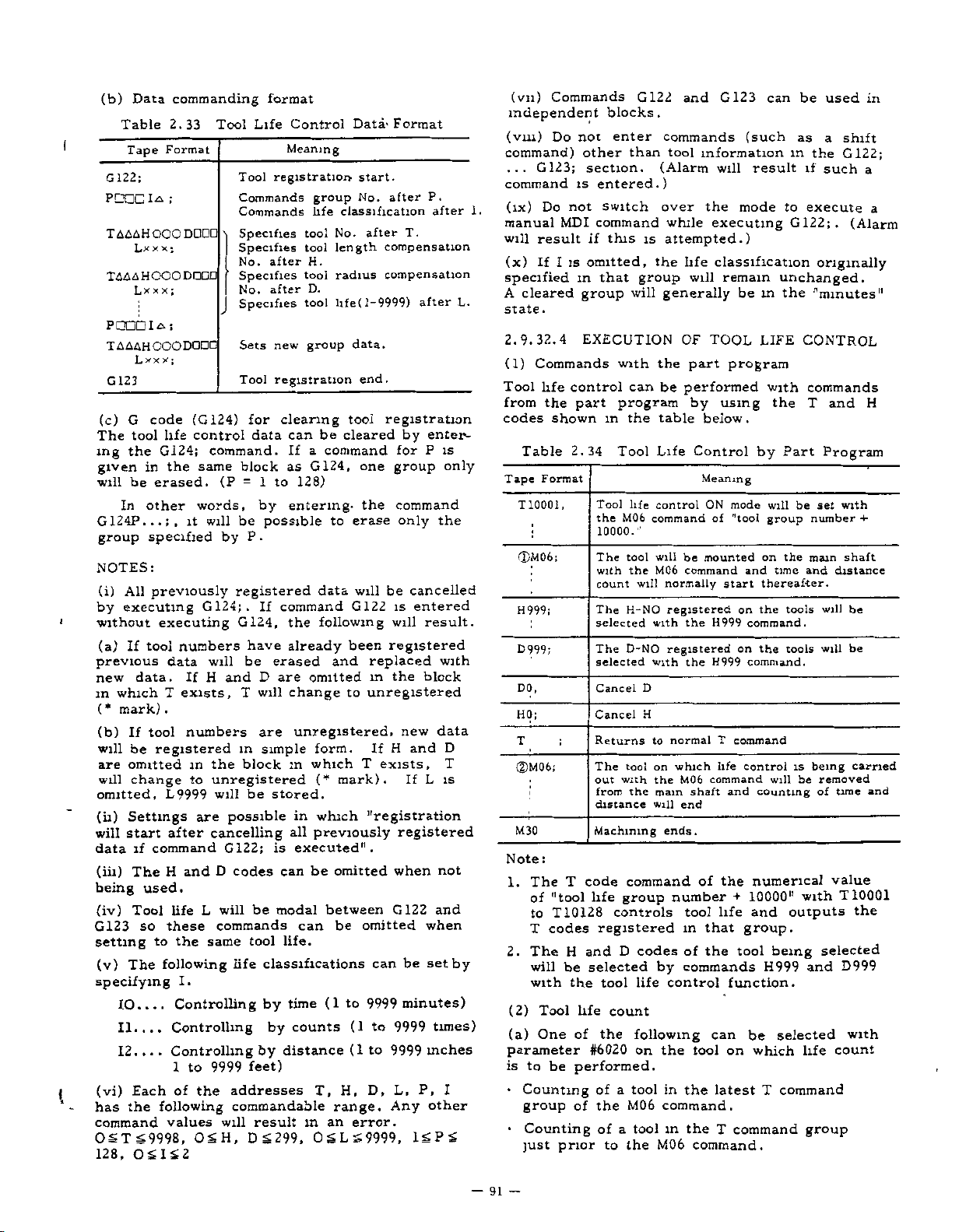
I
1
(b)
Data
Table
Tape
122;
G
I
PCEC
TAAAHOOO
Lxxx;
TAAAHOOO
Lxx
POODIai
TAAAHOOO
G
(c)
The
ing
given
will
G124P...;,
group
123
G
tool
the
be
In
x
x
L
code
in
other
specified
NOTES:
(i)
All
previously
by
executing
without
(a)
previous
new
m
(*
(b)
will
are
will
omitted,
(ii)
will
data
(iii)
being
(iv)
G123
setting
(v)
tool
If
data.
which
mark)
tool
If
be
omitted
change
Settings
start
if
The
used.
Tool
so
The
command
to
specifying
10....
II....
12.
..
(vi)
Each
the
has
command
OSTS9998,
128,
OSIS2
commanding
2.33
Format
;
DODO
DODD
x
;
DODD
y
;
(G124)
life
control
G124;
the
same
erased.
words,
it
will
G124;.
executing
numbers
data
H
If
exists,
T
.
numbers
registered
in
to
L9999
are
after
and
H
L
life
these
same
the
following
I.
Controlling
Controlling
Controlling
.
to
1
the
of
following
values
OSH,
format
Tool
Life
Tool
registration
Commands
Commands
Specifies
Specifies
after
No.
Specifies
after
No.
Specifies
Sets
Tool
for
data
command.
block
(P
1
=
by
be
possible
.
P
by
registered
If
G124,
have
be
T
m
block
erased
D
will
are
simple
will
and
the
unregistered
be
will
stored.
possible
cancelling
G122;
D
codes
will
be
commands
tool
life
classifications
by
by
by
feet)
9999
addresses
commandable
will
result
DS299,
Control
Meaning
group
life
tool
tool
H.
tool
D.
tool
group
new
registration
clearing
can
be
command
a
If
G124,
as
128)
to
entering-
data
command
following
the
already
omitted
are
change
unregistered,
form.
in
which
(*
which
in
previously
all
executed".
is
be
can
modal
between
can
life.
(1
time
counts
distance
T,
an
m
OSLS9999,
Data-
start.
No.
classification
No.
after
data.
end.
tool
1
—
compensation
compensation
9999)
registration
length
radius
life(
cleared
one
the
erase
to
be
will
G122
been
and
replaced
in
to
unregistered
If
exists,
T
mark).
"registration
omitted
omitted
be
can
9999
to
(1
to
(1
to
H,
D,
range.
error.
Format
after
P.
after
T.
after
enter¬
by
is
P
for
group
command
the
only
cancelled
is
entered
will
result.
registered
with
block
the
data
new
and
H
If
IS
L
registered
when
not
and
G122
when
set
be
minutes)
times)
9999
inches
9999
P,
L,
I
other
Any
ISPS
L.
only
D
T
by
1.
(vn)
Commands
independent
(vm)
command)
...
Do
G123;
command
(IX)
Do
not
manual
will
(x)
result
If
I
MDI
is
specified
A
cleared
.
state
2.9.32.4
(1)
Commands
life
Tool
from
codes
control
the
shown
Table
Format
Tape
T1Q001,
(DM06;
H999;
D999;
DO,
HO;
;
T
©M06;
M30
:
Note
T
The
1.
"tool
of
T10128
to
codes
T
2.
(2)
(a)
parameter
is
•
H
The
will
be
with
Tool
One
to
be
Counting
the
group
•
Counting
just
prior
blocks
enter
not
than
other
section.
entered.)
is
switch
command
this
if
omitted,
in
that
group
EXECUTION
with
can
program
part
2.34
in
Tool
Tool
the
10000."
The
with
count
The
selected
The
selected
Cancel
Cancel
Returns
The
out
from
distance
Machining
code
life
the
life
M06
tool
the
H-NO
D-NO
tool
with
the
command
group
controls
registered
D
and
selected
tool
life
count
the
of
#6020
performed.
of
a
the
of
to
M06
a
the
of
G122
and
.
commands
tool
information
(Alarm
over
while
is
attempted.)
life
the
group
will
will
D
H
codes
life
following
on
tool
tool
will
generally
OF
the
part
be
performed
by
table
Life
Control
control
commandof"tool
be
will
M06
command
normally
registered
the
with
registered
the
with
normalTcommand
to
which
on
the
M06
shaft
main
will
end
ends.
of
number
tool
m
of
by
commands
control
the
tool
in
the
command.
in
the
M06
command.
G123
(such
result
will
mode
the
executing
classification
remain
be
TOOL
program
using
below.
by
Meaning
ON
mode
mounted
and
start
on
command.
H999
on
command.
H999
control
life
command
and
the
numerical
10000"
+
and
life
that
group.
the
tool
function.
can
be
on
which
latest
T
command
can
in
to
G122;.
unchanged.
the
in
LIFE
with
the
Part
be
will
group
the
on
time
thereafter.
the
tools
tools
the
is
will
counting
outputs
being
H999
selected
command
T
be
used
as
a
shift
the
G122;
if
such
execute
(Alarm
originally
'’minutes"
CONTROL
commands
T
and
Program
set
wtth
number
shaft
main
and
distance
be
will
be
will
carried
being
removed
be
of
time
value
10001
T
with
selected
D999
and
with
count
life
group
in
a
a
H
+-
and
the
—
91
—
Page 100

2.9.32.3
(CONT'D)
(b)
Tool
distance
regard
(c)
When
The
control
tool
is
(D
of
mode.
one
time
required
and
feed
(d)
When
The
cutting
(every
be
will
exceeds
(e)
When
The
count
T9999Lÿaa;
the
table
omitted,
(f)
The
during
count
T9999Lÿ-ÿ£>
Selection
M02/M30
(g)
The
count
2.9.32.5
Control
(1)
Settings
(D6)
#6004
Clears
command
Does
0:
#6204
Specifies
change.
D5
#6020
(2)
Parameters
D7
#6020
Specifies
(TLSKP)
0:
Currently
1:
External
D6
#6020
Selection
command.
Latest
0:
Immediately
1:
Tool
life
or
input"
tool
actually
the
table
Life
minute
for
dual
tool
second)
increased
1
inch
tool
will
in
LI
count
the
cannot
of
roust
maximum
not
will
Parameters
data
life
not
group
However,
is
group
of
T
Life
count
counts
is
in
life
will
count
used
in
count
is
single
operation
life
distance
outlined
by
or
life
increase
the
in
section
be
will
can
M02/M30
increased
be
M02/M30
and
whether
made
be
value
above
go
registered
clear
number
"0,"
Setting
number
specified
signal
command
T
a
command
Prior
Control
not
will
when
ON
state.
is
set
every
the
in
para.
be
will
exceeded.
block
set
is
is
calculated
in
"1"
1
foot.
set
is
by
section
(1)
equivalent.
be
increased
command.
to
count
with
for
9999.
and
when
is
this
1
for
group
(TL1
to
T
command
Data
be
the
"tool
time
by
second
section
(1)
and,
increased
stop,
will
not
distance
by
para.(c)
each
count
by
"L"
between
executed.
is
by
the
in
parameter
USED
Settings
prior
Clears
1:
resetting
only
128
to
tool
TL64)
group
Setting
performed
life
in
between
in
However,
feed
be
counted.
by
and
time
when
the
(I)
by
However,
incorporating
same
with
T9999Laaa
is
9999
for
to
effective
change
during
count
which
the
by
hold,
the
interval
life
the
command
and
If
"1"
program.
#6020.
so
Tool
G122;
the
for
skipping
an
time,
by
dis¬
and
0
cutting
1
each
the
time
fast
count
distance
(2)
of
is
L
only
the
the
Life
tool
when
M06
the
or
Setting
/M
Counts
Counts
D5
number
D4
selection
#6020
Group
(TLRST)
0:
#6020
T
0:
1:
2.9.32.6
(1)
Format
(a)
A
the
(b)
was
(c)
IS2,
different
G122
P
command
made
A
numerical
ST
0
OSD
(d)
Intervened
(2)
Alarm
This
execution
(a)
(b)
in
(3)
This
T9999
(a)
object
(b)
is
A
A
one
Alarm
is
When
The
an
command
command
group.
command
group
although
M02/M30.
(c)
The
was
Alarm
is
H(D)
All
T5
Tool
999.
Do
Even
If
320
will
If
display
not
of
digit
not
will
the
m,
OVR
it
(4)
This
the
(a)
the
(b)
unregistered
H(D)
NOTE:
(1)
executing
(2)
control
commands
(3)
or
This
capacity
(4)
will
#6204
with
with
Alarm
errors
or
in
£
was
126:
error
of
127:
an
error
a
T5
T9999L
the
T9999L
a
life
128:
an
error
999
command
the
command
numbers
rewrite
life
M06
if
not
T1QQ01
part
use
then
that
by
and
SKP
command
when
T9999L
M02/M30
Code
address
G123
block.
was
G122.
value
9998,
commanded
in
when
life
a
was
was
m
function
digit
was
not
parameter
A-AA
control
in
groups
(*
mark)
control.
is
be
through
program
m
13
reduce
amount.
SKP
on
1:
External
tool
Details
of
alarm
neglected
other
0
<L<
G122
there
control
entered
entered
a
T5
command
registered.
command
the
fuction.
were
was
H-NO
when
the
executed
executed.
memory
the
as
the
occur
a
priority
for
tool
input
life
control
on
Tool
125:
G122/G123/G124
command
and
than
9999,
0£H<
G122.
in
a
with
was
data
digit
is
an
for
for
was
was
for
was
manual
command.
257
17
command
classification
T5
digit
m
SKP
executed.
and
D-NO
executing
life
control
manual
in
Do
T10I28
capacity
life
tool
program
part
the
at
same
basis.
change
(TL1
is
Life
was
made
T
command
ISP
299,
MDI.
overflow
or
more
or
more
executed,
executed
a
count
executed
count.
command
status
were
command
data
MDI,
not
in
manual
control
time,
reset
to
by
count
Control
£128,
and
during
and
with
although
when
found
when
execute
150
is
data.
memory
T-NO
TL64‘
in
0£
tools.
tools
a
the
and
life
MDI.
m
92
-
—
 Loading...