

Page 1
mtsr
xJMW
SnSsSM?
pr
m
1
a
fU
'v~v
tr
gw
thoroughly,
W
tor
Before
read
future
these
/r?rt/e/
/nsfrucf/ons
and
reference.
opera
retain
ffon
T0E-CQ43-7.30C
INSTRUCTIONS
$8ÿ
g
fÿM
Wm
YASN.
_
tt&
Hi
m
give
and
N
Y
J
s
E
operators
opera¬
optional
features
tool
G
A
Z
U
P
K
T
F
MJ*»
/
•
A
I
7
C
B
V
W
Q
H
0
8
I
I
R
I
9
5
6
4
3
1
2
0
m
to
programming,
basic
optional
specifications
the
the
machine
0
X
I
%
M
L
JB
MX1.
refer
intended
MX1
to
the
The
For
to
f
IJSL
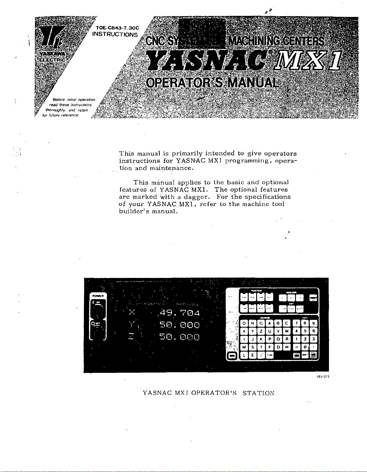
This
instructions
are
of
builder's
tion
This
features
marked
your
manual
and
•f
X
0,2?
\
/
y
V
1
h.
is
for
maintenance.
manual
YASNAC
of
with
YASNAC
manual.
:
•
\»*i
"*
,49.
50.
50.
primarily
YASNAC
applies
a
dagger.
MX1,
704
000
000
YASNAC
MX
1
OPERATOR'S
*81-273
STATION
Page 2
PREFACE
Read
this
mation
possible
The
operations
should
functions
The
determined
NC
control.
the
machine
over
ority
1.
2.
2.1
2.
2.3
2.
2.
2.6
2.
2.
2.
2.
2.1
3.
3.1
3.2
3.3
3.4
4.
CHARACTER
4.1
4.2
4.
4.4
4.5
4.6
4.7
4.8
5.
5.1
5.
manual
contained
contingency
not
not
be
attended
and
combination
a
by
For
builder's
tool
this
manual.
INTRODUCTION
PROGRAMMING
Format
Input
2
Program
Coordinate
4
Traverse
5
Spindle-Speed
Function
Tool
7
Tool
Compensation
8
Miscellaneous
9
Preparatory
10
user
Message
User
PART
Tape
Macro
PROGRAM
Code
1
Programming
NC
Tape
NC
Tape
NC
OPERATOR'S
Pushbuttons,
Power
On
3
Display
Tape
Input/Output
Loading
138
Edit
Input
Data
Verifying
Tape
READER
TAPE
Reader
Tape
T
2
ape
Reels
keeping
herein
to
described
performance
operation
Number
Word
and
Feed
Function
(T-Functton)
Functions
Function
Displayÿ
(C65
110
Punching
113
DISPLAY
Lamps
Operation
/Off
Writing
and
programs
Part
/Output
Compartment
’
149
in
does
be
with
manual
1
and
and
110
145
148
mind
not
met
with
in
the
as
of
machine
of
your
I
1
Sequence
6
Functions
(S-Function)
14
(M-
(C-Function)
C66)
TAPE
113
STATION
114
and
Operation
Operations
Into
Interface
that
cover
the
this
control.
NC
NC
shall
TABLE
13
Function)
83
84
CODINC
Keys
119
of
Memory
148
the
every
manual
machine
machine,
take
Number
9
WITH
114
120
NC
140
infor¬
operation.
the
and
pri¬
OF
13
15
21
110
CRT
DATA
135
Unless
apply
ples
•
Least
•
are
Feed
*
Absolute
•
Reference
(Return
matic
•
Dimensions:
CONTENTS
6.
MACHINE
6.
1
Switching
6.
2
Operation
6
132
OPERATION
7.
7.1
Inspection
7.2
Turning
Manual
7.3
7.4
Preparation
Compensation
7.5
Preparation
7.6
Operation
7.7
Manual
Operation
7.8
Automatic
7.9
MDI
Operation
7.10
Preparation
7.11
Turning
MAINTENANCE
8.
8.
1
Routine
8.2
Battery
8.3
Power
4
8.
Thermal
8.
5
Others
8.6
Trouble
APPENDIX-1
APPENDIX-
APPENDIX-3
COMPENSATION
APPEND!
OUTPUT
otherwise
the
to
shown
Input
Function
return)
Operation
and
Operation
175
Operation
1
76
Off
Inspection
Replacement
Circuit
Overload
Causes
2
4
X-
SIGNALS
description
in
this
Increment:
Zero
Zero
reference
to
CONTROL
Units
Procedure
PROCEDURE
Before
on
Power
for
Stored
for
in
Tape
Operation
Interrupting
for
Power
Breaker
155
LIST
LIST
STORED
LIST
specified,
manual.
Selection:
Point:
Point
:
Qk
MM
in
on
the
Turning
173
173
Stored
Stroke
Automatic
and
Interrupting
in
Turning
176
178
Schedule
Relay
and
Remedies
OF
SETTING
OF
PARAMETER
LEADSCREW
209
OF
STANDARD
213
of
zero
STATION
Control
163
on
Leadscrew
Limit4ÿ
Operation
Memory
Mode
MDI
Automatic
Off
Power
181
Fuses
and
of
Servo
the
following
programming
0.01
mm
(mm
G94
manual
by
155
Station
/
73
Power
Error
173
Mode
Automatic
175
176
178
182
Unit
185
NUMBERS
NUMBERS
ERROR
INPUT/
173
173
175
/min.)
1
55
184
rules
exam¬
and
auto¬
187
192
APPENDIX
APPENDIX-
5
LIST
OF
ALARM
6
LIST
OF
ADDRESS
COOES
CHARACTERS
222
234
Page 3
INDEX
Subject
Absolute
A
Absolute
Address
ADDRESS
ADDRESS
Address
Alarm
Alarm
ALARM
Alarm
Alarm
Argument
Automatic
Automatic
Automatic
AUTOMATIC
Automatic
Automatic
Axis
AXIS
B
Battery
BATTERY
Breakpoint
Buffer
C
Cable
Canned
Cautions
Circle
Circuit
Circuit
Circular
Circular
(M97/M96)
Command
Considerations
Constant
Control
Control
Coordinate
COORDINATE
CRT
Current
CURSOR
CYCLE
D
DATA
Data
Setting
DATA
Decimal
Display
DISPLAY
DISPLAY
DRY
Dwell
Zero
/Incremental
and
Function
CHARACTERS,
Keys
Search
Code
Display
Codes
and
CODES,
Message
Number
Designation
Acceleration
Centering
Coordinate
OPERATION,
Return
Tool
Control,
INTERLOCK
REPLACEMENT
Function
Storaget
Connector
Cycles
in
Programming
Cutting
Breaker
Breaker
Interpolation
Path
t
Data
Display
Commands
Panel
Word
Character
Position,
Keys
START
INPUT
Input
/Output
of
Keys
Point
and
Write
AND
LOCK
RUN
Switch
(G04)
(G92)
Point
Programming
Remedies
OF
LIST
Display
User
of
Function
System
to
Reference
length
4Th
Input
•
Specifications
(G73,
G74,
G13)+
(G12,
for
Servo
of
Composite
Mode
On/Off
Display
and
Remarks
•
* *
WORD
Display
Displaying
Pushbutton
/OUTPUT
Interface
Programming
of
Local
WRITING
/MACHINE
,
Programming
Characters
LIST
by
#8000
Macro
*
*
and
Deceleration
(G36,
Settingf
PREPARATION
Measurement
*
(G02,
INTERFACE,
Point
•
G76,
....
•
Control
Control
G03)
Tool
on
for
and
and
to
Variables
OPERATION
LOCK
(G90,
OF
Command
4
-
•
G3?)+
(G28)
+
G77,
•
Power
Radius
User
Resetting
Lamp
SUPPLEMENT
be
used
and
Switch
of
G91)
•
*
•
G80
Macros
* *
and
Common
•
•
FOR
+
G98,
G89,
to
Supply
Compensation
Rate,
Baud
Variable
TO
Unit
G99)+
*
C
•
Chapter
2
2
2
APPENDIX
4
4
*
*
4
•
8
APPENDIX
2
2
*
2
•
2
2
6
7
2
6
• •
2
6
8
8
•
4
2
4
2
••
3
2
*
8
.
8
•
-
2
2
4
*
•
2
4
2
•
8
2
2
4
4
4
6
4
4
4
2
•
•
2
4
6
6
2
Section
2,9.31
2.9.30
2.1.1
*
6
5
4.1.4
4.3.10
4.3.10
8.6.2
*
•
2.10.1
2.11,10
2.11.2
2.4.6
2.9.19
6.2.2
7.5
2.9.14
6.2.3
2.3.4
6.1.29
8.1.4
2
8.
4.3.11
2.1.5
4.7.4
2.9.29
3.2.3
2.9.9
8.3.5
8.3.1
2.9.4
2.8.6
4.3.2
2.
11.9
4.3.1
2.11.6
8.1.2
2.3.1
2.3
4.1.2
4.3.4
4.1.8
6.1.2
4.7
4.7,2
4.1.5
2.1.3
2.11.8
4.3
1.21
6.
6.1.20
2.9.6
Page
79
79
3
234
116
.....
130
.....
130
185
222
83
----
105
86
----
12
----
37
-
444
•
164
173
.....
.....
.....
.....
......
......
......
.....
......
......
34
164
444
*
•
8
•••ÿ
162
180
181
131
5
114
68
112
28
183
182
24
19
121
102
----
120
99
179
7
6
115
124
117
155
140
140
116
5
102
120
160
160
27
ii
Page 4
Subject
EDIT
£
EDIT
EDIT
Editing
Keys
LOCK
E1A/ISO
EMERGENCY
Stop
Exact
Exercises
EXTERNAL
FI-Digit
F
Feed
Function
FEED
HOLD
Feed
Per
Feedrate
Feedrate
FEEDRATE
FEEDRATE
FUNCTION
Fuse
Blowing
for
Fuse
of
Fuses
of
Fuses
Codes
G
G
G06)
(GOO,
(G01)
Linear
G03)
(G02,
G03)+
(G02,
(G04)
Dwell
(G09,
G61,
(G10)
Tool
Gl3)t
(G12,
(G17,
G18,
G21)ÿ
(G20,
(G22,
G
(G27)
Reference
(G28)ÿAutomatic
(G29)ÿReturn
(G30)ÿReference
(G31)ÿSkip
1
(G33)
Threadcutting
G37)T
(G36,
(G38)ÿZ-Axis
(G40,
G41,
G44,
(G43,
(G45
to
(G5Q,
G51)rScaling
(G52
to
4-
(G60)1
Unidirectional
(G70,
G71,
(G73
G74,
,
(G80,
G81)ÿOutput
(G90/G91)
(C92)
Programming
G95)1
(G94,
(G100
through
Switch
Operation,
Auto-Recognition
STOP
(G09,
G61
User
of
Macro
DECELERATION
Programmingt
Designation
Pushbutton
Revolution+
(F-Function)
.........
1/10
OVERRIDE
OVERRIDE
Keys
(Alarm
Control
Servo
Composite
Input
Power
Groups
and
Positioning
Interpolation
Circular
Helical
G64)
Exact
Value
Offset
Circle
G19)
Plane
Inch/Metric
23)
+
Stored
Point
Return
from
Point
Function
Automatic
Reference
G42)+Tool
G49)"*’Tool
G48)
Tool
Position
G59)tWork
G72)
Hole
G76,
G80
Absolute
Feed
Function
102)
Summary
Pushbutton
G64)
,
and
CANCEL
Switch
331,
No.
Power
Control
Unit
,
of
List
Interpolation
Interpolation
Stop
Designation
Cutting
Designation
Designation
Stroke
Limit
Check
to
Reference
Return
Centering
Surface
Radius
Length
Offset
Function
Coordinate
Approach
Pattern
G89,
to
External
for
/Incremental
of
Absolute
Designation
High-Speed
of
•
Input
G95)t
(G94,
Lamp
Switch
332)
Unit
Power
Supply
Reference
Zero
Function
Offset
Compensation
Compensation
System
Cycles
G98,
Motion
Programming
Zero
Cutting
INDEX
*
*
+
s
Signal
•
*
*
•
...
.
•
*
-
-
Unit
....
G
by
Code
.
Point
•
Setting
.
G99rCanned
Point
•
Feature
* *
*
*
ion
•
*
•
Sect
4.
6
4.1.
6.1.28
4.8.4
3.1.2
6.1.4
2.9.7
2.
ii.
6.
1.30
2.4.4
2.9.32
6.1.3
2.4.5
2.4.2
2.4.3
6.1.13
6.1.12
4.1.3
8.4.1
8.3.4
8.3.2
8.3.3
2.9.1
2.9.2
2.9.3
2.9.4
2.9.5
2.9.6
2.9.7
2.9.8
2.9.9
2.9.
2.9.
2.9.12
2.
9.13
2.9.14
2.9.
2.9.16
2.9.
2.
9.
2.9.19
2.
9.
2.9.21
2.9-
2.9.23
2.9.24
2.9.
2.9.26
2.9.27
2.9.29
2.9.
2.9-30
2.9.31
2.9.32
2.9.33
Page
10
138
117
162
146
-
•
110
.
155
.
n
27
105
162
.
.
.
.
.
11
80
155
12
10
11
159
157
.
115
.
184
183
182
183
21
23
23
24
26
27
27
28
-
10
11
15
28
31
31
32
33
34
35
36
17
18
20
22
36
37
37
39
39
53
55
60
25
62
64
65
68
28
67
79
79
80
80
Chapter
4
4
6
4
3
6
2
2
6
2
2
6
2
2
2
6
6
4
8
8
8
8
2
2
2
2
2
2
2
2
2
2
2
2
*
2
2
2
2
2
2
*
C
2
2
2
2
2
2
2
2
2
Cycles
•
•
-
2
2
2
2
2
2
iii
Page 5
INDEX
Subject
H
andD-function
H-
HANDLE
HANDLE
HANDLE
Helical
AXIS
Dial”!'
Dials
Interpolation
High-Speed
Pattern
Hole
l
Inch/Metric
Input
Format
INPUT
Input
FORMAT
/Output
Input/Output
INSPECTION
Interface,
Internal
Toggle
INTRODUCTION
JOG
J
L
M
FEEDRATE
JOG
Pushbuttons
Skip
Label
Input
Least
Linear
Interpolation
(MOO,
M01
(M90
(M91/M90)t
(M93/M92)+
(M95/M94)
(M97/M96)+
Compensation
(M98,M99)
M
M
M
Codes
Codes
Codes,
to
M199)
for
for
M-FUNCTION
MACHINE
Maintenance
MAINTENANCE
MANUAL
MANUAL
MANUAL
TION
MANUAL
MANUAL
Manual
Maximum
Message
MDI
MDl
MEM
MIRROR
Mirror
Miscellaneous
MISCELLANEOUS
MODE
Return
Display
MODE,
OPERATION
DATA
IMAGE
Image
SKI,
(H,
Select
(Manual
for
Simultaneous
Cutting
Cycles
Designation
Signals
Signals,
3EFORE
and
Type
Switches
Switch
Function
Increment
,
M02,
M30)
M
Codes
Program
Active
Multi-
Mirror
Image
Circular
C
Subroutine
Internal
(MOO,
Stop
Call,
*
LOCK
Before
Other
CONTROL
ABSOLUTE
OPERATION
OPERATION
MULTIPLY
PULSE
REFERENCE
to
Reference
Programmable
by
AUTOMATIC
INTERRUPTING
(Memory
AXIS
On
/Off
Function
EOT
FUNCTION
Switches
Codes)
D
Switchÿ*
(G02,
Feature
(G70,
Generator)
Pulse
G03)
(G100
G71,
G
by
Displaying
TURNING
Functions
........
•
and
Least
(G01)
Codes
M
Internal
for
Interruption
Registers
On
/Off
Mode
Path
Program
Processing
,
M01
Switch
(Auxiliary
STATION
Switch
INTERRUPTING
Select
POINT
Point
Dimensions
Control-Out
OPERATION
Data)
Keys
SELECTOR
(M95/M94)
(B-Function)
• • •
*
*
Control
*
of
•
+
through
G72)+
(G20,
Code
On/Off
POWER
ON
* *
of
Output
Stop
for
Processing
On
/Off
On/Off
On
M02,
RETURN
(M-FUNCTION)
on
/Off
(M90
to
M30)
Function
AUTOMATIC
Switch+
Switcht
Control-In
and
IN
AUTOMATIC
Switch
,
2Nd
+
up
G102)
....
G21)t
of
*
•
Increment
Tool
99)
Ml
...
to
Three
*
* *
Radius
. . .
*
*
Lock)
OPERA¬
OPERATION
Axes*
*
.
Chapter
**
.
.
•
Section
2
6
6
6
2
2
2
2
2
2
8
4
7
4
4
1
6
r
6
2
2
2
2
2
2
2
2
2
2
2
2
2
6
2.7.3
6.
1.6
6.
1.5
6.
1.8
2.9.5
2.9.33
2.9.27
2.9.11
2.1.1
2.1
8.6.3
4.3.13
7.1
4.7.1
4.3.8
6.1.10
6.
1.9
2.
1.4
2.3.5
2.9.
2.8.1
2.8.2
2.8.3
2.8.
2.8.5
2.8.6
2.8.7
2.
8.
2.8.
2.8.8
6.
1.23
6
8
8
6
7
7
6
6
6
2
2
7
7
4
6
2
2
2
6
•
8.6.4
6.
7.2
7.7
6.1.7
6.1.
6.2.
2.3.6
2.
7.
7.9
4.
6.
2.8.5
2.8.9
2.8
6.1.1
1.24
10.
8
1.11
1.25
3
4
2
L
•••
15
1
••
2
Page
14
156
156
157
26
80
65
31
-
1
1
185
132
173
140
•
130
1
157
157
5
8
23
15
16
16
6
1
16
19
19
16
15
20
160
155
186
178
160
173
175
156
159
163
9
83
175
176
117
160
16
•
•
20
15
•
155
;
iv
Page 6
Subject
.Multi-
M
N
O
P
Active
Multi’
Active
OPERATOR'S
NC
NC
TAPE
NC
Tape
NC
Tape,
NC
Tape
NC
TAPE
NEXT
Key
On-Line
Operation
OPERATION
OPERATION
Operations
Operation
Optional
OPTIONAL
OPTIONAL
(Origin)
ORG
OTHERS
Output
Overload
Overview
Keys
PAGE
Paper
Tape
PARAMETER
Parameters,
Part
Program,
Part
Program
Part
Program
Part
Program
Part
Program
Part
Program
PART
PROGRAM
Program
Part
Part
Program
Part
Program
Part
Program,
PROGRAMS
PART
Plane
Designation
Playback
Positioning
POWER
POWER
Power
On/Off
PREPARATION
PREPARATORY
Process
Program
Program
PROGRAM
PROGRAMMING
PROGRAMMING
Registers'
Registers
*
Check.
Keeping
Punch
PUNCHING
...
Diagnostics
Commands
PROCEDURE
PROCEDURE
using
Time
Block
BLOCK
STOP
for
External
(Alarm
of
User
Select
NUMBERS,
Displaying
Display
Form,
Tape
Tape
to
Function
(GOO,
CIRCUIT
/OFF
ON
Sheet
Interruption
Number
NUMBER
STATION
*
*
Data
Display
(/l-/9)
Skip
SKIP
Switch
Key
Motion
No.
Macro
Adding
Block,
Block,
MDI
by
General
TAPE
into
Verifying
Paper
Making
INTO
(GI7,
G06)
BREAKER
OPERATION
Pushbuttons
TURNING
FOR
FUNCTION
AND
On
/On
Input
Switch
352)
,
351
Body
LIST
and
......
Deleting
Modifying
,
Loading
.
-
CODING
Memory,
Tape,
Addition
MEMORY,
G18,
On/Off
SEQUENCE
CRT
WITH
/Output
•
•
+
(G80,
G81)T
*'*
OF
Writing
-
*
Loading
Outputting
*
to
LOADING
9)
1
G
FUSES
AND
POWER
OFF
(G-FUNCTION)
(M91/M90)t
INDEX
•
CHARACTER
Interface
*
*
*
•
* *
*
*
*
•
•
-
NUMBER
DISPLAY
V
huptc'f
••
4
3
3
3
3
3
4
8
2
6
7
4
4
2
6
6
4
8
2
8
2
4
3
APPENDIX
4
4
4
4
4
4
3
3
4
4
4
4
4
2
6
2
8
4
4
7
2
3
2
2
2
3
2
\
St'-.
lv'<
1
.
t
2.
S.
4
3.
3.3.3
3.4.2
3.3.2
3.3
4.1.6
8.6.
2.11.5
6.2
4.7.5
4.
3.9
2.2.3
6.1.19
6.
1.
4.
1.9
8.5
2.
9.
8.4.
2.11.3
1,7
4.
3.3.1
•
2
4.3.7
4.6.
4.6.2
4.6.3
5.
4.
4.6.
3.2.2
*
5,
4.
•
4.8.3
*
4.4,
*
4.
5.
4.5
•
2.
9.
*
6.2.5
•
2.9.2
•
8.3
•
4.2
*
4.
1.
7.
10
*
2.9
•
2.
3.
2,8.3
-
-
2.2.1
•
2.2
*
3.2
P.-'sjV
t-
1
114
l
13
----
113
113
113
113
116
1
18
28
2
4
3
1
1
5
2
10
1
I
185
99
163
----
173
144
----
130
6
159
...
159
----
117
185
67
184
----
87
----
117
113
.....
192
128
139
138
139
137
138
112
110
135
145
133
.....
136
135
31
.....
170
23
182
119
115
176
21
1
10
16
6
6
10
1
1
v
Page 7
INDEX
Subject
Program
P
PUSHBUTTONS,
Rapid
R
RAPID
Reference
REFERENCE
Reference
Registration
Registered
Remote
RESET
Return
ROUTINE
S
S2-Digit
5-Digit
S
Scaling
Sequence
Servomotor
Setting
Setting
Setting
Setting
SETTING
Setting
Simultaneously
Simultaneously
SINGLE
Function
Skip
SPINDLE
SPINDLE-SPEED
Splicing
STANDARD
START
STORED
STORED
STORED
Stored
Subroutine
SWITCHING
T
T2-Digit
T4-Digit
Feed
Tape
TAPE
Code
Tape
TAPE
TAPE
TAPE
Reader
Tape
Tape
Reader
TAPE
TAPE
Tape
Reels,
Reels,
Tape
TAPE
Restart
Traverse
TRAVERSE
Point
POINT
Point
of
Program
On
Power
Key
from
Reference
INSPECTION
Programming
Programming
Function
Number
and
Parameter
and
and
Data
and
Data
Data,
Displaying
NUMBERS,
of
Baud
BLOCK
(G3I)+
SPEED
Tape
NC
INPUT
Input
LOCK
LEADSCREW
LEADSCREW
STROKE
Stroke
AND
CODE
FEED
INPUT
READER
READER
Limit
Program
UNITS
Programming
Programming*
Switch
MEMORY
and
/OUTPUT
•
Handling
Handling
REELS’*"
RATE
(G27)+
Lamps+
Macros
Number,
Pushbuttons
Zero
SCHEDULE
t
(G50,
G51)t
.......
•
Motor
Tape
Parameter
Parameter
LIST
and
/OUTPUT
(or
ERROR
ERROR
LIMIT*,
(G22,
(M98,
THE
ON
AND
OVERRIDE
(G30)t
.
*
for
Verifying
Data,
Data
and
OF
Others
Axes
Axes
Switch*
Switch)
PREPARATION
G23)*
M99)
LAMPS
Rate
Check
Return
User
/Off
DC
Rate
Controllable
Controllable
Switch
OVERRIDE
FUNCTION
...
and
System
MODE,
SYSTEM
-
-
COMPARTMENT
OPERATION
No.
OPERATIONS
i
8-inch
6-inch
KEYS
Switch
.....
•
.
*
No.
•
.
.
Inputting
to
Paper
of
Serial
of
Four-axis
of
Three-
Switch
of
•
«
*
LIST
STATION
IN
OF
NC
Display
(G29)ÿ
Spindle
Writing
(S-FUNCTION)
SIGNALS,
COMPENSATION
COMPENSATION
CONTROL
Switches
*
*
•
*
-
Tape,
Ingerface
axis
•
OF
FOR
....
DATA
Outputting
Controlt
Control
•
AND
•
•
*
•
.
•
:
•
Chapter
6
4
2
6
2
6
2
2
.
.
4
.
.
4
.
.
4
2
8
2
2
2
2
8
4
4
•
4
•
4
APPENDIX
4
2
2
6
2
6
2
3
APPENDIX
6
APPENDIX
7
2
2
6
2
2
5
7
3
3
4
4
5
8
5
5
5
5
5
Section
6,2.4
...
4.1
2.4.1
6.1.11
2.9.13
6.1.16
16
2.9.
2.11.7
4.5.4
4.2.3
4.1.12
2.9.15
8.1
2.5.1
2.5.2
2.9.24
2.2.2
8.1.3
4.8.1
4.4.2
4.4.4
1
«
•
-
-
4.3.6
4.7.3
2.3.3
2.3.2
6.1.17
2.9.17
1.
14
6.
2.5
1
3.4.
4
6.1.27
3
7.4
2.9.12
2.8.7
6.
1
2.6.1
2.6.2
5.
1.
I
7.6
3.
1.
1
•••
3.1
4.1.13
4
4.
5.
1.2
8.1.1
5.1
5.2.2
5.2.1
5.2
Page
•
167
114
----
••
•*
.....
.....
••
•••
.....
......
......
9
157
33
159
36
101
137
120
118
35
178
----
13
13
60
6
179
145
133
133
127
187
141
•
7
7
159
36
159
13
113
213
162
209
----
173
32
----
19
155
14
14
148
175
U0
*
*
•
10
1
118
132
148
----
1.
179
148
148
149
149
149
vi
Page 8
Subject
T
Tape
TAPE
TG
THERMAL
Threadcutting
TOOL
Tool
TOOL
Tool
TOOL
Tool
Tool
Tool
Tool
Tool
Tool
Tool
Tool
TRAVERSE
TROUBLE
TURNING
Turning
TURNING
Turning
TV
Unidirectional
U
USER
User
USER
V
Variables
W
Work
Writing
Z
Z-AXIS
Z-Axis
Tumble
Box
VERIFYING
Error
'Alarm
OVERLOAD
COMPENSATION
Compensation,
FUNCTION
Length
Offset
Offset
Offset
Offset
Offsets
Offsets
Position
Radius
Compensation
LENGTH
Data,
Memory
Value
Value
from
to
Offset
Compensation
AND
CAUSES
OFF
off
Power
ON
POWER
Power
on
(Tape
Check
Approach
Call
in
Blocks
FEED
Reference
(G65,
NEGLECT
MACRO
Macro
MESSAGE
Coordinate
392)
391,
No.
RELAY
~
{
33)
G
Outline
(T-FUNCTION)
MEASUREMENT
Displaying
Designation
Tape
Tape,
Paper
FEED
POWER
Vertical
Commands
DISPLAY
System
and
Surface
*
*
Verifying
Inputting
Tape,
(G45
FUNCTIONS
REMEDIES
AND
(060)+
G66)
Setting
Displaying
Switch
(G43,
to
C
Parity
Offset
SERVO
OF
of
G44,
Pushbutton
and
Writing
(G10)
Outputting
'
G48)
(G40,
Check)
•
(G52
Contents
(G38)i‘
*
*
G41
«
*
*
*
/
to
INDEX
UNIT
G49)
*
and
•
*
•
G42)t
,
G59)ÿ
by
*
Lampt
MDI
tion
•
•
•
•
•
*
• •
*
*
*
•
*
•
•
•
.
•
*
•
•
•
-
•
•
•
-
*
-
-
.
-
•
*
•
*
i>i*v
5.1.3
4.8
8.4.3
8.4
2.9.
2.7
2.
7.1
2.6
2.9.22
6.
1.
4.3.5
2.7.2
2.9.8
4.8.2
4.4.]
4.4.3
2.9.23
2.9.21
2.4
8.6
7.
11
4.2.2
7.2
2.
4.
3.2.4
2.9.
2.11
2.11.1
10
2.
2.
11.4
2.9.25
4.3.3
6.
1.22
2.9.20
l\UJC>
...
-
18
26
1
26
148
145
184
----
184
37
14
14
13
53
162
126
14
28
145
132
133
55
39
9
185
176
119
173
119
113
64
84
84
83
84
62
•••
123
160
39
Chapter
5
.
4
S
2
2
2
2
•
•'
-
2
6
4
.
.
2
•
2
4
4
.
4
•
2
•
•
2
2
8
7
4
7
•
-
-
•
4
•
•
3
2
2
.
•
2
-
2
2
*
*
*
*
•
2
•
4
•
-
6
2
vii
Page 9
INTRODUCTION
1.
YASNAC
The
simultaneously
center,
ing
machining,
feedback
With
cessors
the
gauging
NC
and
corporates
capabilities.
semi-permanent
used
mum
The
ed
2.1
2.1.1
A
6313
in
advantage.
data
in
concept,
INPUT
variable
is
combination
input-output
FORMAT
INPUT
used
MX1
controlling
with
emphasis
unattended
logic
various
compact
a
The
and
and,
FORMAT
block
format
YASNAC
for
is
a
high-performance
automatic
control.
incorporating
LSIs,
design
memory
comprises
programmable
utilize
to
interface
addition
in
conforming
MX1.
or
3
4
placed
axes
operation,
16-bit
YASNAC
the
withawide
each
has
to
CNC
a
of
on
high-speed
micropro¬
MX!
range
permanent,
software
to
been
maxi¬
expand¬
one
conventional
2.
JISÿB
to
for
machin¬
or
in¬
of
interfaces
now
is
modes
new
long-distance
YASNAC
The
machine
edited
storage
PROGRMMING
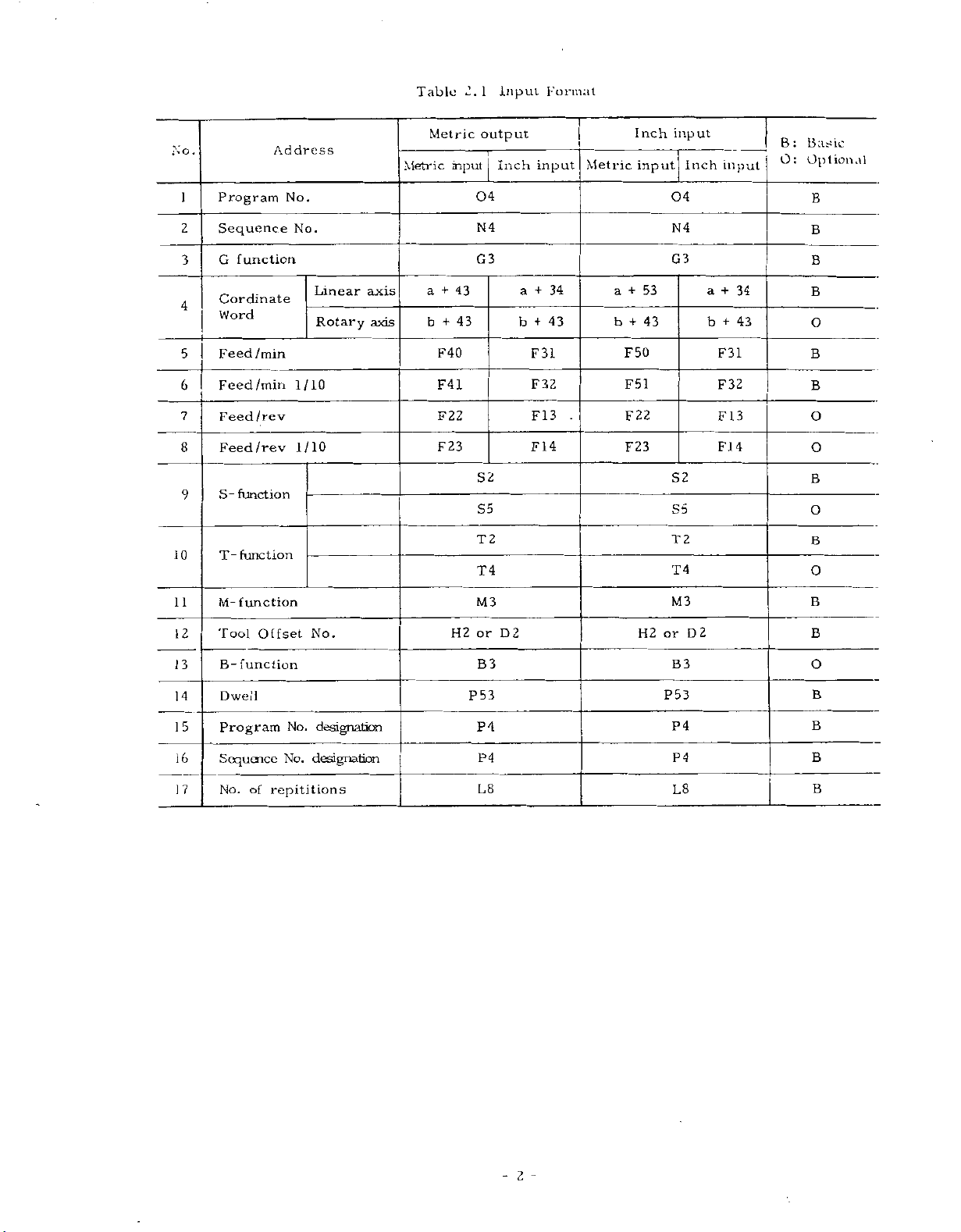
Table
following
indicate
2.
such
available
of
interface,
easily
shows
1
the
the
FACIT
as
accommodate
to
operations
transmission.
data
can
incorporate
and
the
from
input
the
address
programmable
and
such
the
NC
operator's
characters
number
RS
as
a
logic
format.
232C,
requirements
high-speed,
RS
programmable
diagram
in
of
can
station.
Numerals
Table
digits.
422
for
be
2.
1
EXAMPLE
X
Note:
A
decimal
gramming
decimal
point
when
points,
PROGRAMMING.
The
dress
but
In
gram
In
(ISO
colon
leading
codes.
all
the
example
actual
code)
(
zeros
minus
manual
programming,
should
)
;
.
should
you
refer
Plus
signs
FOP
.
is
rcpie.-.eiited
can
signs
must
be
make
to
be
(end
used
5
be
omitted
a
program
2.1.3
suppressed
need
be
of
OR
instead
3
I
in
DECIMAL
be
not
programmed.
block!
(E1A
by
code
.semicolon
a
code)
of
actual
pro¬
including
POINT
for
all
ad¬
programmed,
in
a
(:).
or
Ll'/NL
the
semi¬
pro¬
Down
Five
Sign
Address
to
digits
-
Notes:
#
third
of
character:
Metric
04
N
Inch
input
N
04
represents
"a'1
Q,
F.
because
Japanese
decimal
integer
input
G3
4
4
G3
R
and
they
place
X
format
a+43
format
a+34
X,
are
L
are
Industrial
F5
F31
used
|
/
S2
S2
Y,
omitted
Standard
Z,
for
in
mm
or
inches
T2
T2
I,
in
various
D(H)2
M3
D(H)2
M3
J
K.
or
the
above
meanings.
B3;
B3;
format
1
-
Page 10
No.
Address
Table
Metric
Metric
input
2.
InpuL
1
output
Inch
Format
input
Metric
Inch
input
input
Inch
input
B:
O:
Bathe
Optional
10
11
12
2
3
4
5
6
7
8
9
Program
Sequence
G
function
Cordinate
Word
Feed
/min
Feed
/min
Feed/rev
Feed
/rev
S-
function
function
T-
M-
function
Tool
Offset
No.
No.
1/10
1
Linear
Rotary
0
1
/
No.
axis
axis
+
+
F50
F51
F22
F23
53
H2
43
04
B
B
G3
+
34
a
+
43
b
F31
F32
FI3
F14
S2
S5
T2
T4
M3
2
or
D
B
B
O
B
B
O
O
B
0
B
O
B
B
04
N4 N4
G3
+
a
43
43
+
b
F40
F41
F22
F23
+
34
a
b
43
+
a
b
F31
F32
.
F13
F14
S2
S5
2
T
T4
M3
H2
or
D2
13
14
15
16
17
B-
function
Dwell
Program
Sequence
of
No.
No.
No.
designation
repititions
designation
B3
P53
P4
P4
L8
B3
P53
P4
P4
L8
O
B
B
B
B
-
2
Page 11
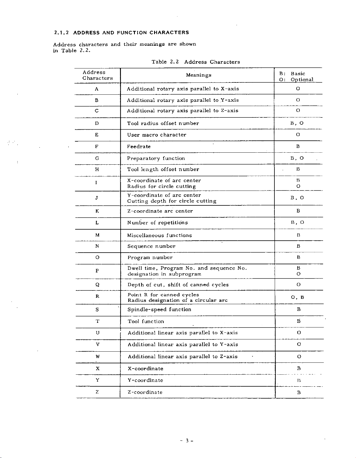
2.1.2
Address
Table
in
ADDRESS
characters
2.2.
AND
FUNCTION
their
and
CHARACTERS
meanings
are
shown
Address
Characters
A
B
C
D
E
F
G
H
I
J
K
L
Additional
Additional
Additional
Tool
radius
User
macro
Feedrate
Preparatory
Tool
length
X
-coordinate
Radius
Y
for
-coordinate
Cutting
Z-coordinate
Number
Table
rotary
rotary
rotary
offset
character
offset
circle
depth
of
repetitions
2.2
function
of
arc
of
arc
for
center
arc
Address
axis
axis
axis
number
number
center
cutting
center
circle
Meanings
parallel
parallel
parallel
cutting
Characters
to
X-axis
Y-axis
to
to
Z-axis
B:
Basic
Q:
Optional
O
O
O
B,
0
O
B
O
B.
B
B
O
,
O
B
B
,
O
B
M
N
O
P
Q
R
S
T
U
V
W
X
Y
Z
Miscellaneous
Sequence
Program
Dwell
number
time,
designation
cut,
Depth
Point
Radius
of
R
for
designation
Spindle-speed
function
Tool
Additional
Additional
Additional
X-coordinate
Y-coordinate
Z
-coordinate
functions
number
Program
in
canned
linear
linear
linear
subprogram
No.
of
shift
cycles
of
function
axis
axis
axis
and
canned
circular
a
parallel
parallel
parallel
sequence
cycles
arc
to
X-axis
to
Y-axis
to
Z-axis
No.
B
B
B
B
O
0
O,
B
B
B
0
O
O
B
I’.
B
-
3
-
Page 12
2.1.2
ADDRESS
AND
FUNCTION
CHARACTE
RS
(CONT
'D)
EIA
Blank
2-4-5
2-4-7
BS
Tab
CR
SP
ER
UC
LC
Code
bits
bits
+
ISO
LF/NL
.
Nul
BS
HT
CR
SP
Code
%
(
)
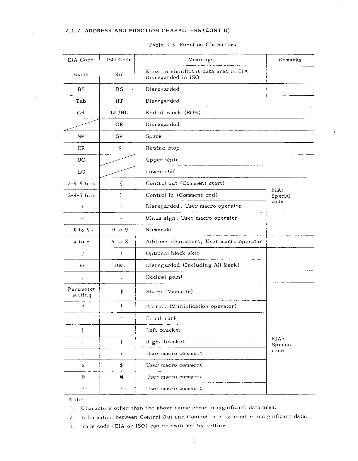
Table
Error
2.3
in
Disregarded
Disregarded
Disregarded
End
of
Block
Disregarded
Space
Rewind
Upper
Lower
shift
shift
Control
Control
Disregarded,
Function
significant
in
(EOB)
stop
(Comment
out
(Comment
in
Meanings
ISO
User
Characters
data
start)
end)
macro
area
operator
Remarks
in
EIA
;
EIA:
Special
code
to
0
9
z
to
a
l
Del
Parameter
setting
*
I
$ $
macro
Minus
•
0
A
to
to
DEL
9
Z
/
Optional
Disregarded
umerals
N
Address
sign,
Decimal
#
*
—
Sharp
Astrisk
Equal
Left
Right
User
User
User
mark
bracket
bracket
macro
macro
macro
User
characters,
skip
block
(Including
point
(Variable)
(Multiplication
comment
comment
comment
operator
User
All
operator)
macro
Mark)
operator
EIA:
Special
code
Notes
1.
Z.
3.
?
:
Characters
Information
code
Tape
other
between
(EIA
User
the
macro
above
can
?
than
Control
ISO)
or
Out
be
comment
cause
and
switched
error
Control
by
4
-
in
In
setting.
significant
is
ignored
data
as
insignificant
area.
data.
Page 13
2.1.3
Numerals
as
the
DECIMAL
dimensional
coordinates
Decimal
dress
words.
Coordinate
U,
Time
Feed
EXAMPLE
V,
W,
word:
rate
X15.
5
Y20.
(G94)F25.6
containing
(distance),
points
words:
Q,
R
P
word:
—
POINT
can
[
X15.
Y20.
F25.0
(for
data
be
X,
F
mm]
000
500
F4.0)
PROGRAMMING
decimal
a
of
addresses
and
time
in
used
Y,
mm
mm
mm/min
the
Z,I,J,
or
or
or
may
point
speed.
following
K,
[
inch
X15.0000
Y
20.
F25.6
(for
be
related
B,
A,
]
inches
inches
5000
inches/min
F3.1)
used
to
ad¬
C,
2.1.5
,
During
read
made
blocks
in
for
contain
2,1.6
For
between
read
BUFFER
normal
advance
in
for
the
the
In
data
of
advance
next
the
up
MULTI-ACTIVE
the
portion
M93
in
advance.
M
code
M92
operation,
follow-on
tool
radius
or
and
compensation
operation
128
to
and
REGISTER
and
compensation
compensation
up
to
is
characters
part
of
M92,
Multi-active
block
one
operation.
4
blocks
computing
executed.
including
REGISTERS
programs
blocks
5
up
to
Meaning
register
of
data
computing
C+mode,
of
data!
One
EOB
t
sandwiched
of
off
is
read
are
required
block
.
data
is
two
can
in
are
G95F.2+
G04P1.
Normally,
inputted,
(or
0.0001
parameter
regard
to
2.1.4
In
becomes
CRT.
•
•
While
on
neglected.
the
dicates
end
"l"
parameter
LABEL
the
cases
When
When
the
the
punched
MEM
of
the
-
when
the
inches,
setting,
as
named
effective,
power
the
the
RESET
label
When
(memory)
the
presence
part
F0.20
(
for
Dwell
data
control
mm
1
#601
SKIP
skip
tape
program.
mm/rev
F2.
,
1
000
without
regards
0.001
or
the
(or
9q6)
•
FUNCTION
below,
and
supply
key
function
up
LSK
EDIT
or
of
2)
control
inch
1
LSK
is
is
to
is
displayed
a
pointer
or
sec
a
decimal
"1"
deg.),
may
or
label
the
is
displayed
turned
pushed.
effective,
is
the
first
(editing)
F0.200
(for
as
but
be
1
deg.).
on
at
inches/rev
3)
FI.
point
0.001
with
made
skip
on.
EOB
the
mode,
the
mm
to
Refer
function
on
the
all
code
CRT
it
leading
is
a
data
are
in¬
power
control
stoppage
made
so
time
ready
Multi-active
is
is
in
can
that
reading
of
advance
not
is
to
be
M93
Note;
reset,
marked
When
the
with
Inter-block
of
is
advance
program
time
processing
blocks
NOTE:
Advance
but
M93
in
of
is
always
mode.
data.
reading
applied
the
be
the
5
of
reading
made
made
register
or
state
eliminated
automatic
blocks
for
up
the
every
to
of
is
of
on
control
M
code
when
operation
longer
next
blocks
5
5
blocks
is
the
than
5
in
-
5
-
Page 14
7.1
2.2.1
PROGRAM
PROGRAM
NUMBER
NUMBER
AND
SEQUENCE
NUMBER
When
search
to
hand
searching
.
or
for
specify
sequence
program
numbers,
numbers
be
sure
before¬
Program
the
for
Up
to
character
program
trol,
and
employing
One
program
with
ends
placed
placed
%
PROGRAM
PROGRAM
(or
ER
the
top
NOTES:
•
The
/M02;
programs.
of
•
To
make
effective
succeeding
program
change.
2.2.2
Integers
following
ten
n
umbers
Sequence
blocks,
meaning
Therefore,
and
tial.
sequence
any
sequential
numbers
numbers
purpose
4
at
at
010;
%
and
blocks
,
digits
may
"0"
as
numbers
to
up
an
option.
begins
M02,
M30
the
ends
ends
the
.....
WITH
NO.
ISO
at
end
for
/M30;
,
the
reading
as
a
ER
ends
(#6021pQ)
SEQUENCE
consisting
an
.
numbers
do
sequence
they
duplicated
number
numbers
not
and
and
.
may
of
program
be
program
can
or
199
with
or
of
of
M02;
r-#r
10
code)
the
of
optional
/M99;
program
(EIA)
possible
is
NUMBER
of
address
are
have
may
numbers,
are
be
prefixed
identification.
written
numbers.
be
registered
can
999
a
program
M99.
main
subprograms.
is
M02
programs,
01234;
PROGRAM
PROGRAM
punched
program.
block
not
are
M02,
of
end,
(ISO)
or
%
with
4
to
up
character
reference
influence
any
machining
of
be
sequential,
is
possible.
also
convenient
to
programs
an
after
be
and
.....
on
skip
regarded
M30,
and
a
digits
numbers
address
Up
in
the
registered
number,
M30
and
M99;
WITH
1234
NO.
the
such
and
make
to
a
as
sign
parameter
may
sequence
N
as
on
to
are
M99
tape
as
as
M99
be
for
the
processes.
non-sequen-
not
also
and
as
Generally,
sequence
99
con¬
and
%
ends
in¬
the
of
writ¬
using
is
<
at
NOTES:
When
number,
trailing
•
When
number,
more
no
•
Blocks
searched
contained
2.2.3
Those
ed
block,
switch
EXAMPLE
blocks
are
OPTIONAL
neglected
when
for
12
When
the
neglected,
is
block
N
"1",
With
NOTES:
•
The
optional
while
ter.
switching
•
While
function
The
optional
function
2.3
COORDINATE
Generally,
and
tions
are
tems
words
axes
directions
consist
and
5
or
only
end
two
only
searching
without
that
N
1234
switch
and
read
1234
"1"
the
If
the
reading
is
.
commands
commands
called
numerals
.
more
the
are
more
or
one
with
for
the
in
which
in
the
number
G01
when
as
if
G01
may
block
blocks
blocks
on
is
or
ineffective.
block
WORD
coordinate
of
digits
digits
effective.
blocks
is
is
sequence
respect
blocks.
BLOCK
between
external
X100/3
/
for
the
X100;
omitted.
be
skipping
are
have
ineffective
punching
skip
for
address
representing
arc
retrieved
performed.
SKIP
11
In"
In
optional
"n"
2
on,
is
switch
.
read
/
movements
for
setting
characters
written
up
to
have
numbers
to
(n
and
is
on.
Y200;
the
process
into
been
to
out
2
words,
as
the
4th
the
same
and
can
the
address
(/1
-
9)
-
1
=
the
block
entire
/
for
the
buffer
read,
skip
programs,
is
an
/9
in
coordinate
and
dimensions
sequence
a
from,
sequence
read,
also
+
/9)
is
includ¬
end
of
skip
block
on,
is
3
executed
is
subsequent
the
blocks.
option
axis
coordinate
for
desired
the
and
be
data
that
is
this
resis¬
this
direc¬
sys¬
of
-
6
-
Page 15
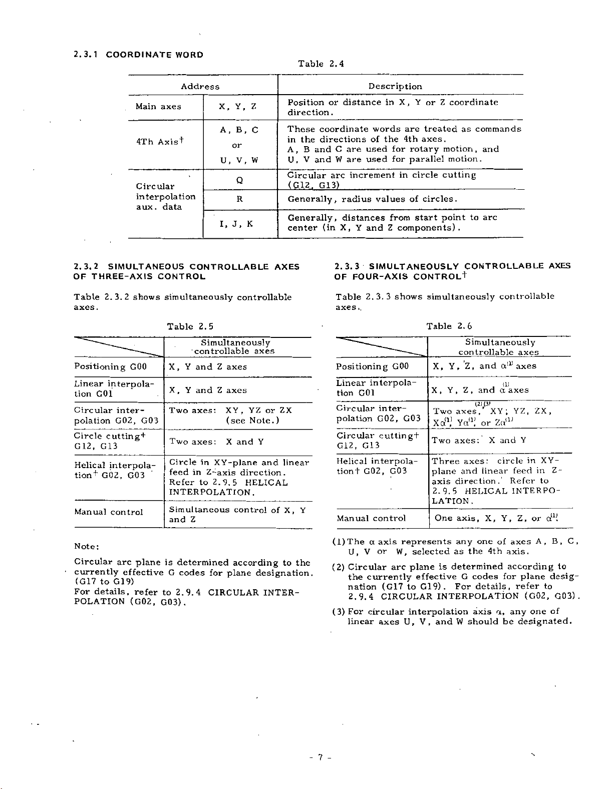
2.3.1
COORDINATE
WORD
Table
2.4
2.3.2
OF
Table
axes
SIMULTANEOUS
THREE-AXIS
2.3.2
.
Positioning
Linear
G01
tion
Circular
polation
Circle
G
Helical
tion'’'
Manual
12,
cutting
G13
G02,
Main
4Th
Circular
interpolation
aux.
shows
GOO
interpola¬
intei
—
G02,
interpola¬
G03
control
Address
axes
Axis’’’
data
CONTROL
simultaneously
Table
X,
,
X
Two
G03
+
Two
Circle
feed
Refer
INTERPOLATION.
Simultaneous
and
Y,
X,
B,
A,
or
V,
U,
Q
R
I,
J.
CONTROLLABLE
controllable
2.5
Simultaneously
controllable
Y
Y
and
and
axes:
axes:
in
to
Z
in
XY-plane
Z-axis
2.9.5
Z
Z
axes
axes
XY
(see
X
control
and
,
direction.
Z
C
W
K
AXES
axes
YZorZX
)
Note.
Y
and
HELICAL
of
Position
direction.
These
the
in
B
A,
U,
V
Circular
(
G12
Generally,
Generally,
center
linear
X,Y
or
coordinate
directions
C
and
and
arc
G13)
,
(in
2.3.3
OF
Description
distance
are
used
W
are
used
increment
radius
distances
X,
Y
and
SIMULTANEOUSLY
FOUR-AXIS
tion
2.
interpola¬
G01
Table
axes
Positioning
Linear
Circular
polation
Circular
G12,
G13
Helical
G02,
tiont
Manual
in
words
of
the
for
for
_
values
from
Z
components).
3.
shows
3
GOO
inter¬
G02,
cuttingf
interpola-
G03
control
X,
Y
or
are
treated
axes.
4th
rotary
parallel
circle
in
circles.
of
start
CONTROL+
simultaneously
Table
X,
X
Two
G03
Xcx1,1
Two
Three
plane
axis
2.9.5
LATION.
One
Z
coordinate
commands
as
motion,
motion.
cutting
to
point
CONTROLLABLE
2.6
Simultaneously
controllable
Z,
Y,
,
Y,Z
axes,
,
and
(21,(3)
Yet11,’
axes:
axes
and
direction.’
HELICAL
,X,Y,
axis
and
arc
and
XY;
or
X
:
linear
controllable
axes
axes
a111
(l)
axes
a
YZ,
Z«a'
Y
and
in
circle
feed
Refer
INTERPO¬
,
Z
or
ZX,
in
to
AXES
XY-
Z-
a11!
:
Note
Circular
currently
(G17
to
details,
For
POLATION
arc
effective
9)
G1
plane
refer
(G02,
is
determined
G
codes
to
2.9.4
G03)
.
according
for
plane
CIRCULAR
to
designation.
INTER¬
the
-7-
(l)The
(2)
(3)
a
V
U,
Circular
currently
the
nation
2.9.4
For
circular
linear
represents
axis
or
W,
selected
plane
arc
(G17
to
CIRCULAR
interpolation
U,
axes
any
as
determined
is
effective
G19).
G
For
INTERPOLATION
V,
and
W
one
the
codes
details,
axis
should
4th
a,
axes
of
axis.
according
for
any
be
A,
plane
to
refer
(G02,
one
designated.
B,
to
desig¬
G03)
of
C,
.
Page 16
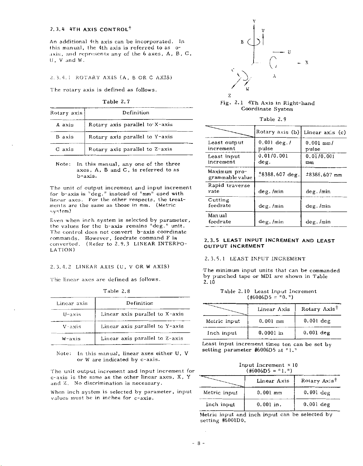
2.3.4
An
this
axis,
U
2.
The
Rotary
The
for
linear
ments
additional
manual,
and
V
and
r
3.
4.
rotary
axis
A
axis
B
C
axis
Note
unit
b-axis
4TH
i
:
axes.
are
system)
when
Even
values
the
control
The
commands.
verted
con
LATION
4.
3.
linear
Linear
2
2.
The
U-axis
-
V
axis
W-axis
Note
:
unit
The
c-axis
and
When
values
is
Z.
inch
AXIS
represents
.
W
ROTARY
axis
axis
In
axes,
b-axis.
of
is
the
inch
for
.
)
LINEAR
axes
axis
In
or
output
the
No
discrimination
system
must
4th
the
is
Rotary
Rotary
Rotary
this
A,
output
Tldeg.,T
For
same
system
the
does
However,
(Refer
are
this
W
are
increment
same
be
in
CONTROL
can
axis
axis
4th
any
AXIS
defined
Table
axis
axis
axis
manual,
and
B
increment
instead
the
other
as
those
b-axis
convert
not
feedrate
2,9.3
to
AXIS
defined
Table
Linear
Linear
Linear
manual,
indicated
the
as
selected
is
inches
+
be
is
of
(A,
as
2.7
Definition
parallel
parallel
parallel
any
C,
selected
is
remains
(U,
2.8
Definition
axis
axis
axis
linear
and
other
is
for
incorporated.
referred
6
the
OR
B
follows.
to1
to
to
one
of
referred
is
and
of
’'mm"
respects,
in
mm.
b-axis
command
LINEAR
W
OR
V
as
follows.
parallel
parallel
parallel
axes
c-axis.
by
input
linear
necessary.
parameter,
by
c-axis.
axes,
C
X-axis
Y-axis
Z-axis
the
input
by
"deg."
AXIS)
to
as
A,
AXIS)
three
to
increment
with
used
treat¬
the
(Metric
parameter,
unit.
coordinate
F
is
INTERPO-
to
X-axis
to
Y-axis
to
Z-axis
either
increment
axes,
as
In
a-
B,
U,
X,
input
B
O
C,
U
X
0
\
0
7
w
Z
2.1
Fig.
Least
output
increment
Least
input
increment
Maximum
grammable
Rapid
rate
Cutting
feedrate
traverse
Manual
feedrate
3.5.
punched
10
Metric
Inch
LEAST
1
LEAST
minimum
Table
input
input
input
parameter
input
input
input
#6001D0.
INCREMENT
2.3.5
OUTPUT
2.
•The
by
2.
Least
setting
V
for
Y
Metric
Inch
Metric
setting
4Th
Coordinate
pro¬
value
INPUT
input
tape
2.
10
(#6006D5
increment
Input
(#6006D5
and
inch
INPUT
or
Least
#6006D5
A
Axis
System
Table
Rotary
0.001
pulse
0.01/0.001
deg.
/min
deg.
/min
deg.
/min
deg.
INCREMENT
INCREMENT
units
are
MDI
Input
-
Linear
0.
001
0.0001
times
Increment
=
Linear
0.
mm
001
0.001
in.
input
in
Right-hand
2.
9
axis
deg.
607
that
shown
"O.”)
Axis
mm
in
ten
11
at
"l.")
Axis
can
(b)
/
deg.
AND
can
be
Increment
Rotary
can
l.!l
x
10
Rotary
be
selected
Linear
0
.
001
mm
pulse
0.01/0.001
mm
±8388.607
deg.
min
/
/min
deg.
/min
deg.
LEAST
commanded
in
Table
0.001
deg
0.
001
deg
set
be
Axis*!*
0.
001
deg
0.001
deg
axis
/
Axisÿ
by
by
(c)
mm
-
8
Page 17
:
Notes
Selection
made
Selection
eter
setting
offset
Tool
(or
mm
is
possible
0.01
In
eration
•
Programming
Write
•
Programming
•
Program
NOTES:
•
NC
If
or
to
increment,
the
intended
•
the
If
contents
machine
the
commanded
•
When
taped,
stored"
ment
of
by
setting
of
value
0.0001
in
mm
increment
must
operation
editing
tape
stored
increment
of
will
the
stored
the
regardless
system.
(#6001D0).
or
1
system
x
metric
x
(#6006D5).
must
inch,
or
units,
these
be
made
for
operation
MDI
in
for
operation
operation
programmed
in
an
equipment
the
machine
dimensions.
system
NC
tape
by
move
dimensions.
program
stored
figures
10
always
0.001
system,
in
the
mode.
are
ten
of
switching
is
by
will
is
stored
times
is
or
inch
made
be
deg+.),
the
unit
TAPE
in
MEMORY
in
EDT
in
0.001
set
move
switched
punched
are
system
param¬
by
written
and
following
0.01
of
modet.
mm
by
ten
in
memory,
or
one
punched
of
the
in
mm.
mode.
is
0.01
times
when
tenth
out
incre¬
is
0.001
offset
op¬
modet.
fed
mm
the
on
out
in¬
the
"as
of
the
incremental
In
exceed
not
In
absolute
axis
value
Note:
a
move
value
mable
dresses
mand
accumulative
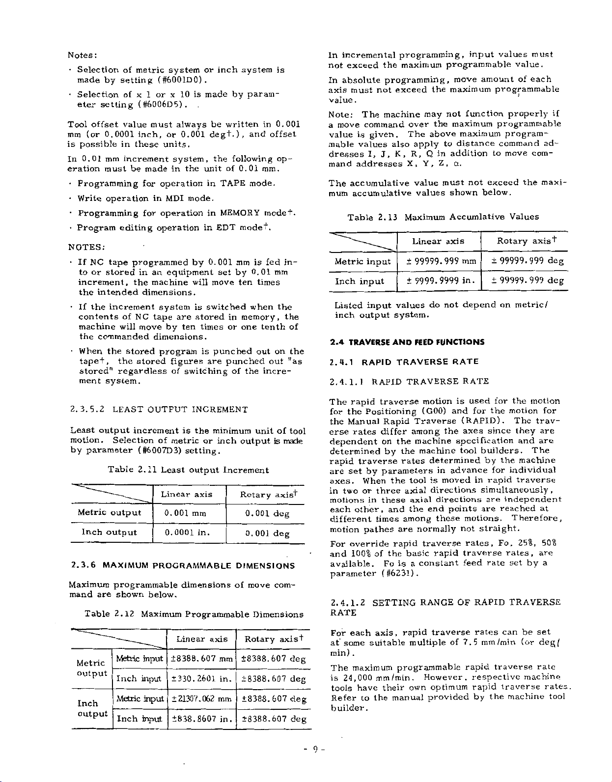
The
mum
Table
Metric
Inch
Listed
inch
2.4
TRAVERSE
2.4.1
2.4.1.1
the
programming,
not
must
.
machine
The
command
is
given.
J,
I,
2.13
input
input
RAPID
also
values
addresses
accumulative
input
output
RAPID
programming,
maximum
exceed
the
may
the
over
above
The
apply
Q
R,
K,
Y,
X,
value
values
Maximum
Linear
99999.
±
9999.9999
±
values
do
system.
FEED
AND
TRAVERSE
TRAVERSE
input
programmable
move
maximum
function
not
maximum
maximum
distance
to
addition
in
Z,
a.
not
must
shown
Accumlative
axis
mm
999
in.
depend
not
FUNCTIONS
RATE
RATE
values
amount
programmable
properly
programmable
program¬
command
to
move
exceed
below.
Values
Rotary
99999.999
±
99999.999
±
on
must
value.
of
each
com¬
the
axist
metric/
if
ad¬
maxi¬
deg
deg
3.
5.
2.
Least
output
motion.
parameter
by
Metric
Inch
2.3.6
Maximum
mand
are
Table
Metric
output
Inch
output
2
LEAST
increment
Selection
Table
output
output
MAXIMUM
programmable
shown
2,12
Metric
Inch
Metric
Inch
OUTPUT
is
of
(S6007D3)
2.11
metric
setting.
Least
Linear
0.001
0.0001
PROGRAMMABLE
dimensions
below.
Maximum
input
input
input
input
Programmable
Linear
±8388.
±330.2601
±21307.062
±838.8607
INCREMENT
the
minimum
or
inch
output
Increment
axis
mm
in.
axis
607
mm
in.
mm
in.
unit
output
Rotary
DIMENSIONS
of
001
0.
0.
001
move
Dimensions
is
axis'!"
deg
deg
com¬
Rotary
±8388.607
±8388.607
±8388.607
±8388.607
of
axis
tool
made
deg
deg
deg
deg
for
the
since
by
for
rapid
are
rate
the
the
reached
Fo,
/min
traverse
the
motion
motion
.
The
they
and
The
machine
individual
traverse
independent
Therefore,
25%,
rates,
set
by
TRAVERSE
be
can
(or
machine
traverse
machine
for
trav¬
are
are
at
50%
are
a
set
deg/
rate
rates.
tool
used
The
rapid
the
for
the
Manual
erse
dependent
determined
rapid
are
set
axes.
two
in
motions
each
different
motion
override
For
100%
and
available.
parameter
2.
4.
1.
RATE
each
+
For
at
min)
The
is
some
24,000
tools
Refer
traverse
Positioning
differ
rates
on
traverse
parameters
by
When
three
or
these
in
other,
times
pathes
of
(#6231).
2
SETTING
axis,
suitable
.
maximum
mm
have
the
to
Rapid
by
the
and
rapid
the
Fo
/min.
their
manual
motion
(GOO)
Traverse
among
machine
the
machine
the
rates
tool
axial
axial
the
among
normally
are
traverse
basic
constant
a
is
RANGE
rapid
multiple
programmable
However,
own
is
and
the
specification
determined
advance
in
moved
is
directions
directions
points
end
these
rapid
OF
traverse
of
optimum
provided
for
(RAPID)
axes
builders.
tool
in
simultaneously,
are
motions.
not
straight.
rates,
traverse
feed
RAPID
rates
7.5
mm
rapid
respective
rapid
by
builder.
-
9
-
Page 18

2.4.2
With
feedrates
tool
med
.
The
programmable
FEEDRATE
digits
five
following
per
FUNCTION)
(F
minute
range
an
(mm
of
address
/min)
feedrates
character
are
program¬
is
as
F,
follows.
G03
Willi
F
(mm
=
X
this
200
/
Y
----
min)
----
command
,
+
I
F200
;
----
2
FY
Metric
output
Inch
output
The
maximum
of
ance
When
the
machine
mable
a
above
feedrate
F
involving
two
tion
EXAMPLE
feedrate
parameter
the
commands
axial
tangential
G01
With
F
=
(mm/min)
Metric
Inch
Metric
Inch
the
maximum
system
set
is
motions
directions
X4000
this
500
input
input
input
input
feedrate
servo
given
(#6228),
maximum
clamped
for
to
G91
command,
3002
J
=
Table
Format
F40
F31
F50
F31
is
system
feedrate
is
below
above,
and
at
the
linear
(incremental)
Y3000
and
in
simultaneously
specify
the
motion
F500
+
4002
2.14
Feedrate
FI.-
F0.1-F313.0
FI.-
F0.
subject
and
set
the
whenever
are
limit
set
circular
feedrates
Y
component
F8100.
F
-
810.0
1
to
the
machine
by
maximum
the
former
commanded,
maximum
path.
;
component
X
(Feed/rrrin)
mm/min
in.
20574.
mm/min
in.
the
perform¬
servo
program¬
is
feedrates
value.
in
the
system.
set
the
interpolations
controlled
min
/
/min
the
direc¬
range
or
by
commands
F
motions
directions
tangential
EXAMPLE
With
F
=
(mm
x
+
for
in
simultaneously
specify
to
the
G01
400
y/fx2
=
min)
/
/
t
CENTER
f\
linear
feedrates
motion
X---
+Y
/
START
POINT
mm/ntin
200
\
fi
z
+
2.3
Fig.
interpolations
controlled
also
path.
Y--.
Z-.-
2
+
Y
f
END
+
POINT
"“V/i
/
y
u
1
involving
three
the
in
;
400
F
fz2
400nun/min
+X
axial
direction
+z
2.4
linear
feedrates
motion
=
Fig.
interpolations
controlled
also
path.
+
fY2
involving
four
axial
the
+
direction
fa2
in
+
fz2
JOG
mm/
min
400
mm/min
2.
I
commands
F
motions
directions
tangential
(mm/min)
F
for
in
simultaneously
specify
to
the
2
10
-
X
+
Fig.
Page 19
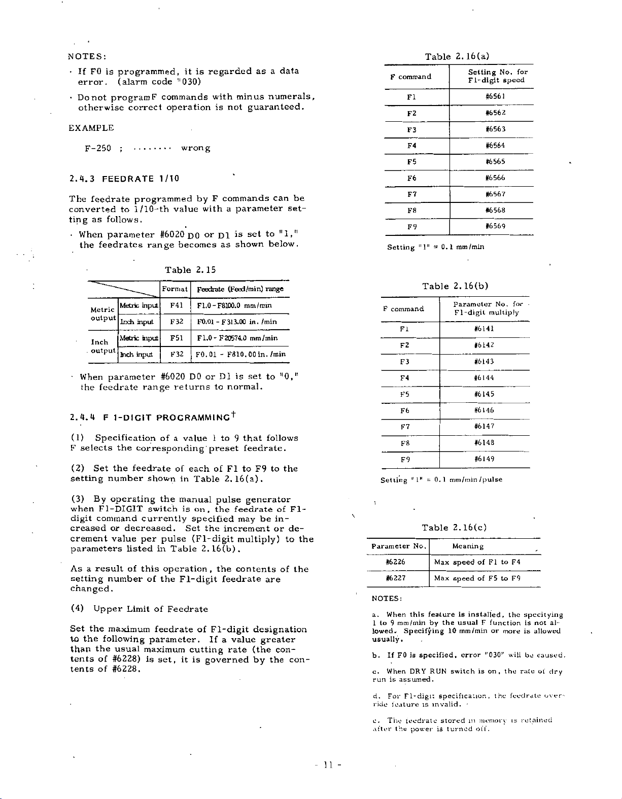
NOTES:
•
FO
If
.
error
•
Do
not
otherwise
EXAMPLE
F-250
2.4.3
The
FEEDRATE
feedrate
converted
as
ting
•
When
feedrates
the
Metric
output
Inch
.
output
When
feedrate
the
2.4.4
(1)
F
(2)
F
Specification
selects
Set
setting
programmed,
is
(alarm
program
correct
;
programmed
1
to
follows.
parameter
Metric
Inch
Metric
Inch
parameter
1-DIGIT
the
the
feedrate
number
regarded
is
it
11
commands
F
operation
030)
with
is
code
wrong
1/10
commands
F
by
with
range
range
value
#6020
becomes
Table
Format
F41
F32
F51
F32
#6020
returns
or
D1
DO
2.
15
Feedrate
FLO-F81DO.O
-
F0.01
FLO
F
-
F0.
01
-
DO
or
D1
to
as
F
20574.0
/10-th
input
input
input
input
PROGRAMMING1*
of
a
corresponding
of
shown
value
each
in
Table
to
1
preset
of
2.16(a).
minus
guaranteed.
not
parameter
a
set
is
shown
(Feed/min)
mm
3.00
in.
31
mm
F810,
00
set
is
normal.
that
9
feedrate.
to
FI
as
/min
in.
F9
to
range
min
/
/min
to
follows
data
a
numerals,
be
can
set¬
11
below.
/min
11
0,"
to
the
F
Setting
command
F
Setting
command
FI
F2
F3
F4
F5
F6
F7
F8
F9
11
FI
F2
F3
F4
F5
F6
F7
F8
F9
1M
"
Table
11
1
=
Table
=0.1
0.1
2.
Parameter
mm/min
2.
mm
F
1-digit
16(a)
Setting
1-digit
F
/min
16(b)
#6561
#6562
#6563
#6564
#6565
#6566
#6567
#6568
#6569
#6141
#6142
#6143
#6144
#6145
#6146
#6147
#6148
#6149
/pulse
No.
speed
No.
multiply
for
•
for
(3)
By
when
FI-DIGIT
digit
command
creased
crement
parameters
As
result
a
setting
changed.
(4)
Upper
the
Set
the
to
the
than
of
tents
of
tents
operating
or
decreased.
value
listed
of
number
Limit
maximum
following
usual
#6228)
#6228.
the
switch
currently
per
pulse
in
this
operation
of
the
of
feedrate
parameter.
maximum
set,
is
manual
is
Set
Table
F
1-digit
Feedrate
cutting
it
on,
the
specified
the
(FI-
digit
2.16(b).
,
of
Fl-digit
If
is
governed
pulse
feedrate
increment
the
contents
feedrate
a
value
rate
generator
be
may
multiply)
are
designation
greater
(the
by
in¬
or
con¬
the
of
Fl-
de¬
to
the
the
of
con¬
11
-
\
\
16(c)
Max
Max
feature
by
the
10
RUN
specification
invalid.
stored
is
turned
2.
Meanin
g
of
speed
speed
is
usualFfunction
switch
of
installed,
mm/min
error
is
•
in
off.
FI
F5
or
,r
0
on,
,
memory
30:r
the
to
to
more
the
F4
F9
the
will
rate
feedrate
retained
is
specitying
not
is
allowed
is
caused.
be
of
over¬
al¬
dry
Parameter
#6226
#6227
NOTES:
a.
When
to
9
1
lowed*
usually.
If
b.
When
c.
run
is
d.
For
ride
feature
e.
The
after
this
mm/min
Specifying
is
F0
DRY
assumed.
Fl-digi;
feedrate
the
power
Table
No.
specified,
is
Page 20
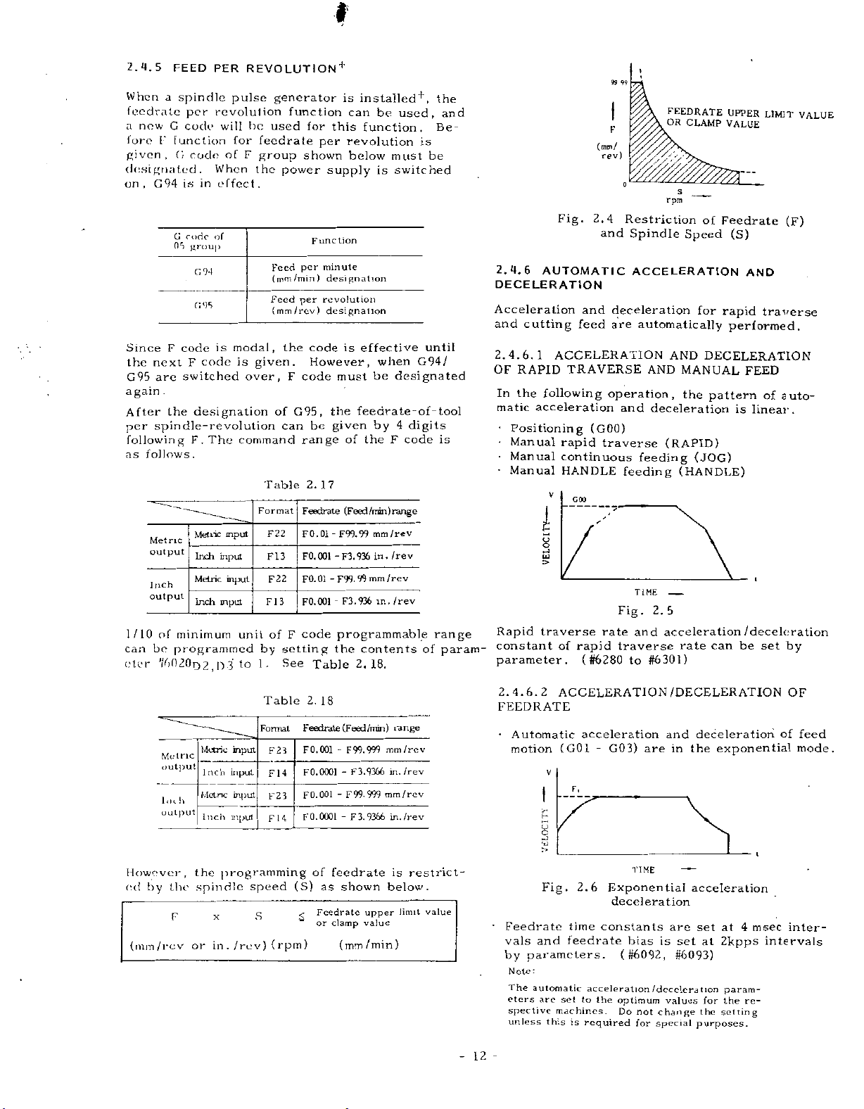
i
I
/
2.4.5
When
FEED
a
feedrate
new
a
fore
given,
G
l*
function
G
designated.
,
G94
on
G
nri
Since
again
F
the
next
G95
are
.
the
After
spindle-revolution
per
following
follows.
as
Metric
output
Inch
output
1/10
of
minimum
bo
can
dor
programmed
W)20D2fD3
spindle
per
code
code
is
in
rode
group
G94
G9S
code
code
F
switched
designation
F.The
Metric
Inch
Metric
Inch
REVOLUTIONÿ
PER
pulse
revolution
be
will
for
of
F
group
the
When
.
effect
of
modal,
is
is
given.
over,
command
Format
input
input
input
input
unit
1.
to
generator
function
used
feedrate
power
Feed
(mm/min)
Feed
(mm/rev)
the
F
of
can
Table
22
F
3
FI
22
F
3
1
F
of
F
by
setting
See
for
shown
per
per
code
However,
code
G95,
be
range
2.
Feedrate
F0.01
FO.
F0.01
F0.001
code
is
can
this
per
revolution
below
supply
unction
F
minute
designation
revolution
designation
is
must
the
given
of
17
(Feed
F99.99
-
001
-F3.936
-
F99.
-
F3.936
programmable
the
Table
installed*,
used,
be
function.
is
be
must
is
switched
effective
when
be
feedrate-of-tool
by4digits
theFcode
/min)
mm/rev
in.
mm/rev
99
in.
contents
2.18.
until
G94/
designated
range
rev
/
/rev
of
the
and
Be¬
is
range
param-
Fig.
2.4.6
AUTOMATIC
DECELERATION
Acceleration
and
cutting
6,1
2.
4.
OF
RAPID
In
the
matic
acceleration
*
Positioning
•
Manual
Manual
•
Manual
Rapid
constant
parameter.
and
feed
ACCELERATION
TRAVERSE
following
rapid
continuous
HANDLE
v
GOO
i
cj
w
>
traverse
rapid
of
(#6280
99
99
i
F
(mm/
rev)
o
2.4
Restriction
and
Spindle
ACCELERATION
deceleration
are
operation
and
(GOO)
traverse
feeding
TIME
Fig.
rate
and
traverse
to
>
FEEDRATE
OR
CLAMP
V,
s
rpm
Speed
for
automatically
AND
AND
MANUAL
,
the
deceleration
(RAPID)
feeding
(JOG)
(HANDLE)
-
2.5
acceleration
rate
#6301)
UPPER
LIMIT
VALUE
of
Feedrate
(F)
(S)
AND
rapid
traverse
performed.
DECELERATION
FEED
pattern
is
of
linear.
auto¬
/deceleration
set
be
can
by
VALUE
However,
ed
by
(mirt/rev
Metric
output
Inch
output
the
F
Metric
Inch
Metnc
Inch
the
spindle
or
x
in
Table
Format
input
F23
input
F
1
input
F23
input
14
F
programming
speed
S
(rpm)
/rev)
.
4
(S)
2.
18
Feedrate
0.001
F
0.0001
F
001
F0.
F0.0OO1
of
as
Feedrate
<
“
or
(Feed
-
F
99.
3.
F
-
99-
F
-
3,
-
F
feedrate
shown
clamp
(mm/min)
/min)
999
9366
999
9366
upper
value
range
mm/rev
/rev
in.
mm/rev
in.
/rev
restrict¬
is
below.
limit
value
2.
FEEDRATE
•
'
-
12
4.6.
Automatic
motion
Feedrate
vals
and
by
parameters.
:
Note
The
automatic
are
eters
spective
unless
2
ACCELERATION
acceleration
(GO
V
r>
Fig.
F.
2.6
time
G03)
-
l
Exponential
constants
feedrate
acceleration
set
to
the
machines.
this
is
required
are
TIME
deceleration
bias
is
(#6092,
/deceleration
optimum
Do
not
change
for
special
/DECELERATION
deceleration
and
the
in
exponential
-
acceleration
at
the
at
for
4
2kpps
param¬
the
setting
msec
re¬
are
set
#6093)
values
set
purposes.
OF
of
feed
mode.
inter¬
intervals
Page 21
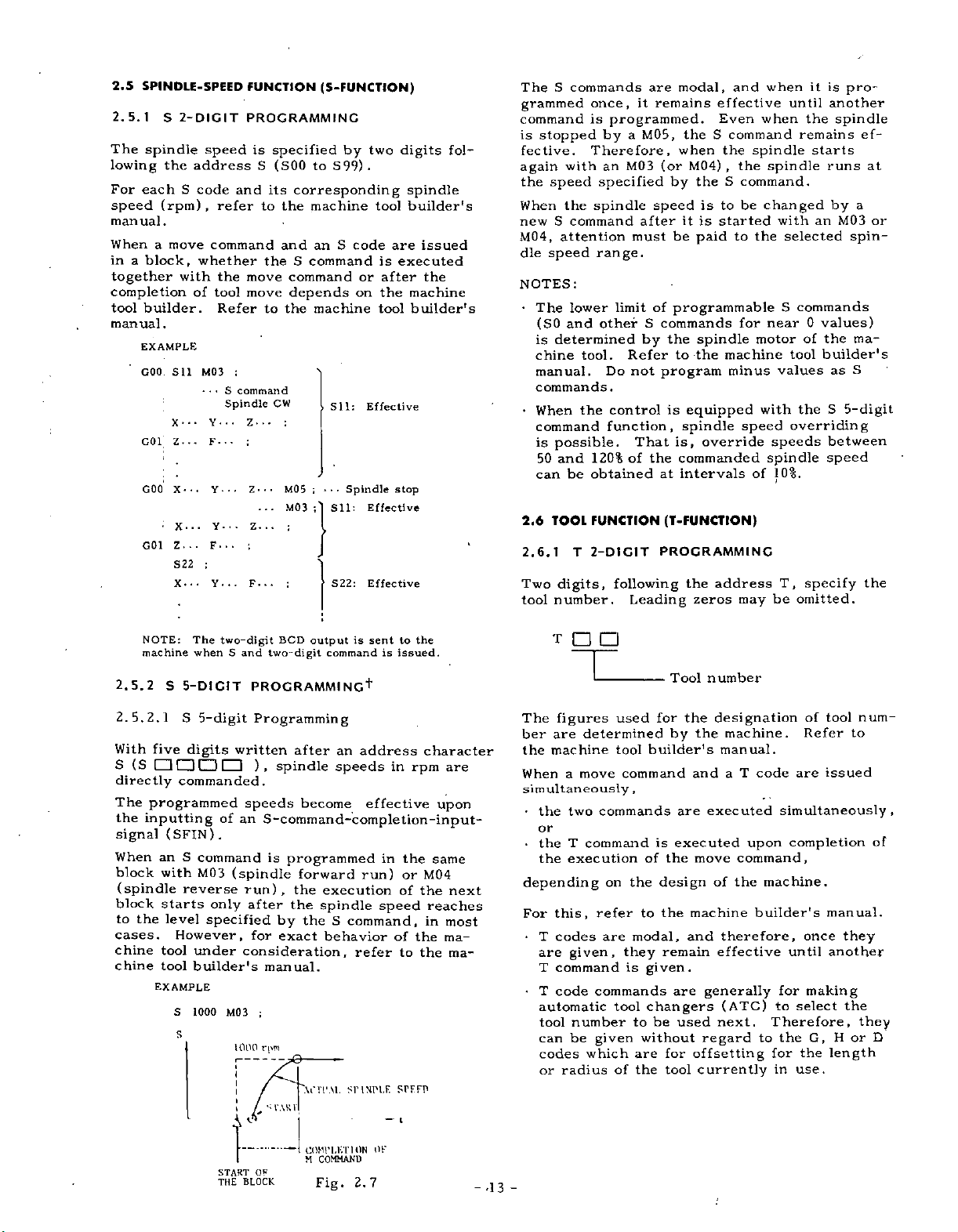
2.5
SPINDLE-SPEED
2.5.1
The
lowing
For
speed
S
spindle
the
each
(rpm)
manual.
When
in
a
a
block,
move
together
completion
tool
builder.
manual.
EXAMPLE
GOO
Sll
X-
G01
Z-
GOO
X-..
X-
Z...
G01
S22
X.
2-DIGIT
speed
address
S
code
,
refer
command
whether
with
the
of
tool
Refer
M03
«
•
•
•
Y
F-
•
-
Y
Y-
•
F...
;
Y-
•
FUNCTION
PROGRAMMING
is
specified
(S00
S
and
its
to
the
and
theScommand
move
move
to
the
;
S
command
Spindle
-
• •
•
CW
..
•
Z
:
;
MO
•
•
Z
•
M03
.
.
z.
:
;
.
.
.
;
F.
•
(S-FUNCTION)
by
S99)
to
corresponding
machine
S
code
an
command
depends
machine
Sll:
;
•
Spindle
*
*
5
Sll:
0
S22:
two
.
tool
is
or
on
tool
Effective
Effective
Effective
are
executed
after
the
stop
digits
spindle
builder's
issued
the
machine
builder's
fol¬
S
The
grammed
command
stopped
is
fective.
again
the
speed
When
S
new
M04,
attention
dle
speed
NOTES:
•
The
(SO
determined
is
chine
manual.
commands.
•
When
command
possible.
is
and
50
can
TOOL
2.6
2.6.1
Two
digits,
tool
number.
commands
once,
is
by
Therefore,
with
an
specified
the
spindle
command
range.
lower
and
other
tool.
Do
the
function,
120%
be
obtained
FUNCTION
2-DICIT
T
are
remains
it
programmed.
M05,
a
(or
M03
by
speed
after
be
must
of
limit
programmable
S
commands
the
by
Refer
not
program
control
is
That
of
the
at
(T-FUNCTION)
PROGRAMMING
following
Leading
modal,
and
effective
Even
theScommand
when
M04)
the
,
spindle
the
theScommand.
to
be
is
started
is
it
paid
to
for
spindle
to
the
machine
minus
equipped
spindle
is,
speed
override
commanded
intervals
the
zeros
of
address
may
when
when
spindle
changed
with
the
S
near
motor
values
with
speeds
spindle
10%.
T,
be
it
until
the
remains
starts
an
selected
commands
values)
0
of
the
builder's
tool
the
overriding
specify
omitted.
pro¬
is
another
spindle
runs
by
a
M03
spin¬
ma¬
S
as
S
5-digit
between
speed
ef¬
at
or
the
NOTE:
machine
2.5.2
2.
5.
2.1
With
(S
S
directly
The
the
inputting
signal
When
block
(spindle
block
to
the
cases.
chine
chine
The
whenSand
S
5-DICIT
S
5-digit
five
digits
commanded.
programmed
(SPIN)
S
an
command
with
M03
reverse
starts
level
specified
However,
tool
under
tool
builder's
EXAMPLE
S
1000M03
s
two-digit
PROCRAMMING
Programming
written
),
speeds
of
an
S-command-completion-input-
.
(spindle
run)
only
after
for
consideration,
manual.
;
1000
rpm
I
i
t
/
V
OF
START
BLOCK
THE
BCD
two-digit
after
spindle
become
is
programmed
forward
,
the
the
by
the
exact
VITAL
V
l‘AK
COMPLETION
M
sent
is
output
commandisissued.
+
an
address
speeds
effective
in
run)
execution
spindle
S
command,
speed
behavior
refer
SIMPLE
—
COMMAND
Fig.
OF
2.7
to
in
or
of
of
to
SPFFD
t
the
character
rpm
the
M04
the
the
the
are
upon
same
next
reaches
in
most
ma¬
rna-
T
number
Tool
num¬
tool
The
figures
are
machine
the
determined
move
a
two
ber
the
When
simultaneously
•
used
tool
command
,
commands
for
the
by
builder's
are
designation
the
manual.
and
executed
machine.
code
T
a
of
to
Refer
issued
are
simultaneously
,
or
manual.
they
another
the
they
or
H
length
of
D
upon
executed
tool
of
the
modal,
they
is
to
are
the
is
the
of
design
the
to
remain
given.
are
changers
be
without
for
tool
move
machine
and
generally
used
regard
offsetting
currently
command,
of
the
therefore,
effective
(ATC)
next.
T
command
the
•
execution
the
depending
this,
For
•
codes
T
are
command
T
•
T
code
on
refer
are
given,
commands
automatic
tool
number
be
can
codes
or
-
-
-13
given
which
radius
completion
machine.
builder's
until
for
to
Therefore,
the
to
for
in
once
making
select
G,
the
use.
Page 22
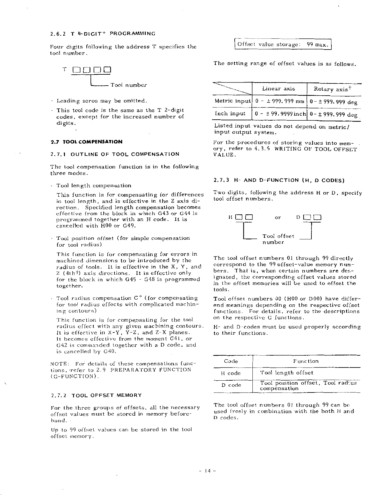
2.6.2
Four
tool
T
digits
number.
-r
n
4-DIGIT
following
n
+
PROGRAMMING
the
address
Tool
number
T
specifies
the
The
("offset
setting
value
range
of
Linear
storage:
offset
axis
99
values
max.
is
as
Rotary
follows.
axisÿ
•
Leading
•
This
tool
codes,
except
digits.
COMPENSATION
TOOL
7.7
tool
modes.
Tool
This
in
tool
rection.
effective
OUTLINE
compensation
length
function
length,
2.7.1
The
three
-
programmed
cancelled
•
Tool
position
tool
for
This
function
machined
radius
Z
for
together.
•
Tool
for
ing
This
radius
It
It
G42
is
NOTE:
tions,
(C-FUNCTION)
2.7.2
For
offset
of
"I)
(4th
the
radius
tool
contours)
function
effect
effective
is
becomes
commanded
is
cancelled
For
-refer
TOOL
three
the
values
hand.
99
to
Up
offset
offset
memory
zeros
code
compensation
Specified
from
with
radius)
dimensions
tools.
axis
block
compensation
radius
effective
by
details
to
OFFSET
groups
must
.
may
is
the
for
the
TOOL
OF
for
is
and
the
block
together
H00
offset
is
for
It
directions.
which
in
effects
is
for
with
any
X-Y,
in
together
G40.
of
PREPARATORY
2.9
.
be
values
be
omitted.
same
increased
COMPENSATION
function
compensating
is
effective
length
or
is
compensation
in
with
G49.
(for
simple
compensating
to
be
effective
G45-G48
C+
with
compensating
given
Y-Z,
the
from
these
compensations
MEMORY
offsets,
of
stored
be
can
the
as
number
is
in
in
which
code.
H
an
compensation
introduced
in
effective
is
It
(for
complicated
machining
and
moment
with
a
all
memory
in
stored
T
2-digit
of
the
following
differences
for
Z
axis
the
for
the
becomes
G44
or
It
errors
by
X,
G43
only
is
programmed
compensating
machin¬
the
for
contours.
Z-X
planes.
G41,
code,
D
FUNCTION
necessary
the
before¬
in
the
is
the
Y,
tool
or
func
tool
and
di¬
is
in
and
Metric
Inch
input
Listed
input
output
For
the
ory,
refer
VALUE.
2.7.3
Two
digits,
offset
tool
H
The
tool
correspond
bers.
ignated,
in
the
.
tools
Tool
offset
end
meanings
functions.
the
on
and
H-
their
to
Code
H
code
D
code
tool
The
freely
used
D
codes.
input
input
procedures
to
AND
H-
numbers.
offset
That
the
offset
numbers
respective
D-codes
functions.
offset
0
-
999.
±
0
99.
-
±
values
do
system.
of
4.3.5
D-FUNCTION
following
Tool
number
numbers
the
to
99
is,
when
corresponding
memories
depending
details,
For
G
must
Tool
Tool
compensation
numbers
in
combination
999
inch
9999
not
storing
WRITING
the
address
or
offset
01
offset-value
certain
will
be
(H00
00
on
refer
functions.
be
used
F
length
position
01
with
mm
depend
values
OF
(H,
D
through
numbers
offset
used
or
the
to
properly
unction
offset
offset,
through
-
0
999.
±
-
0
999.
±
on
TOOL
CODES)
D
H
or
99
memory
values
to
D00)
respective
the
descriptions
Tool
99
both
the
metric/
into
OFFSLT
D
directly
are
offset
have
according
can
999
999
mem-
,
specify
num¬
des¬
stored
differ-
offset
radius
H
deg
deg
the
be
and
14
-
Page 23
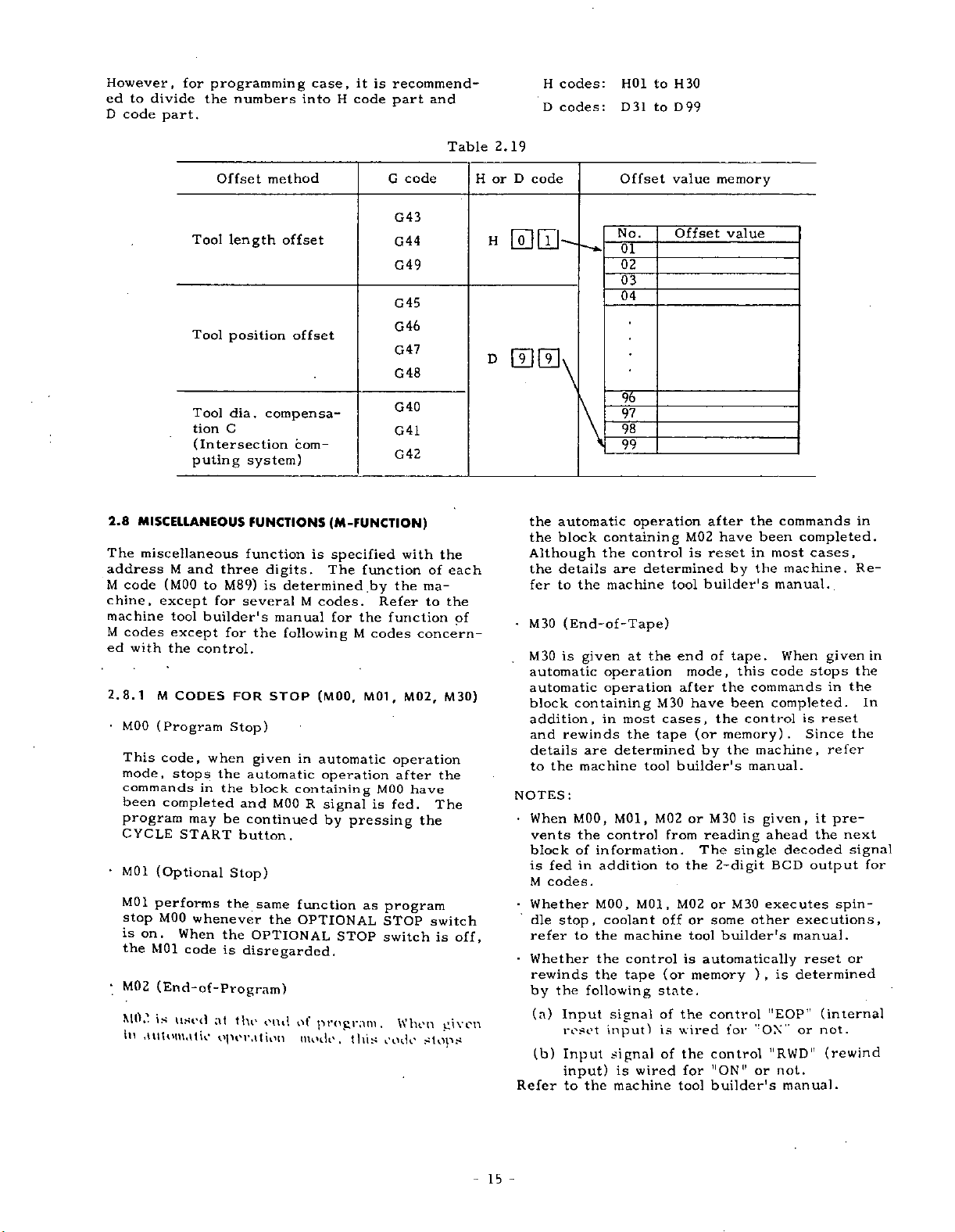
However,
ed
to
code
D
divide
part.
for
programming
the
numbers
into
case,
HOI
D31
to
H30
to
D99
H
code
part
and
recommend¬
is
it
H
D
codes:
codes:
2.8
MISCELLANEOUS
The
miscellaneous
address
M
code
chine,
machine
M
codes
ed
2.8.1
MOO
This
mode,
commands
been
with
M
and
(MOO
except
tool
except
the
M
CODES
(Program
code,
stops
completed
program
CYCLE
•
M01
M01
stop
is
the
M02
MO.)
in
START
(Optional
performs
MOO
on
.
When
M01
code
(End-of-Program)
is
used
automatic
Offset
length
Tool
position
Tool
Tool
dia.
C
tion
(Intersection
puting
three
M89)
to
for
several
builder's
for
control.
FOR
Stop)
when
the
in
the
and
be
may
button.
Stop)
the
whenever
the
is
at
the
operation
method
offset
offset
compensa¬
com¬
system)
FUNCTIONS
function
digits.
is
determined
M
manual
the
following
STOP
in
given
automatic
block
containing
MOO
continued
same
function
the
OPTIONAL
OPTIONAL
disregarded.
end
of
mode,
(M-FUNCTION)
is
specified
The
function
codes.
the
for
M
(MOO,
M01
automatic
operation
R
signal
by
pressing
as
STOP
program.
this
G
by
Refer
function
codes
,
MOO
is
fed.
program
STOP
switch
code
code
G43
G44
G49
G45
G46
G47
G48
G40
G41
G42
with
of
the
ma¬
to
concern¬
M02,
operation
after
have
the
switch
When
stops
the
the
The
is
given
Table
each
the
of
M30)
off,
2.19
D
code
or
H
H
00
Offset
No.
01
value
Offset
memory
value
02
03
04
D
00
\
95"
97
98
99
the
the
automatic
block
the
Although
details
the
to
fer
•
(End-of-Tape)
M30
is
M30
automatic
automatic
block
addition,
rewinds
and
details
the
to
NOTES:
•
When
vents
block
fedinaddition
is
M
codes.
Whether
stop,
dle
refer
Whether
rewinds
the
by
(a)
Input
(b)
Input
input)
Refer
the
given
containing
are
machine
MOO,
the
of
information.
MOO,
to
the
the
the
following
reset
to
the
operation
containing
the
control
determined
are
machine
the
at
operation
operation
most
in
the
determined
tool
M01,
control
M01,
coolant
machine
control
tape
signal
input)
signal
wired
is
machine
M02
is
tool
end
mode,
after
have
M30
cases,
(or
tape
by
builder's
or
M02
from
The
to
the
M02orM30
or
off
tool
is
(or
memory
state.
of
the
wired
is
of
the
for
tool
after
been
have
in
reset
builder's
of
the
by
tape.
this
the
been
the
commands
control
memory)
machine,
the
manual.
M30
is
given,
reading
ahead
single
2-digit
executes
other
some
builder's
automatically
)
,
for
l!EOP’'
"ON"
"RWD"
or
control
control
"ON"
builder's
commands
completed.
cases,
most
machine.
manual..
When
code
stops
completed.
is
.
Since
decoded
BCD
output
executions,
manual.
reset
determined
is
or
not.
manual.
given
in
reset
refer
pre¬
it
the
spin¬
(internal
not.
(rewind
in
Re¬
in
the
the
In
the
next
signal
for
or
15
-
Page 24
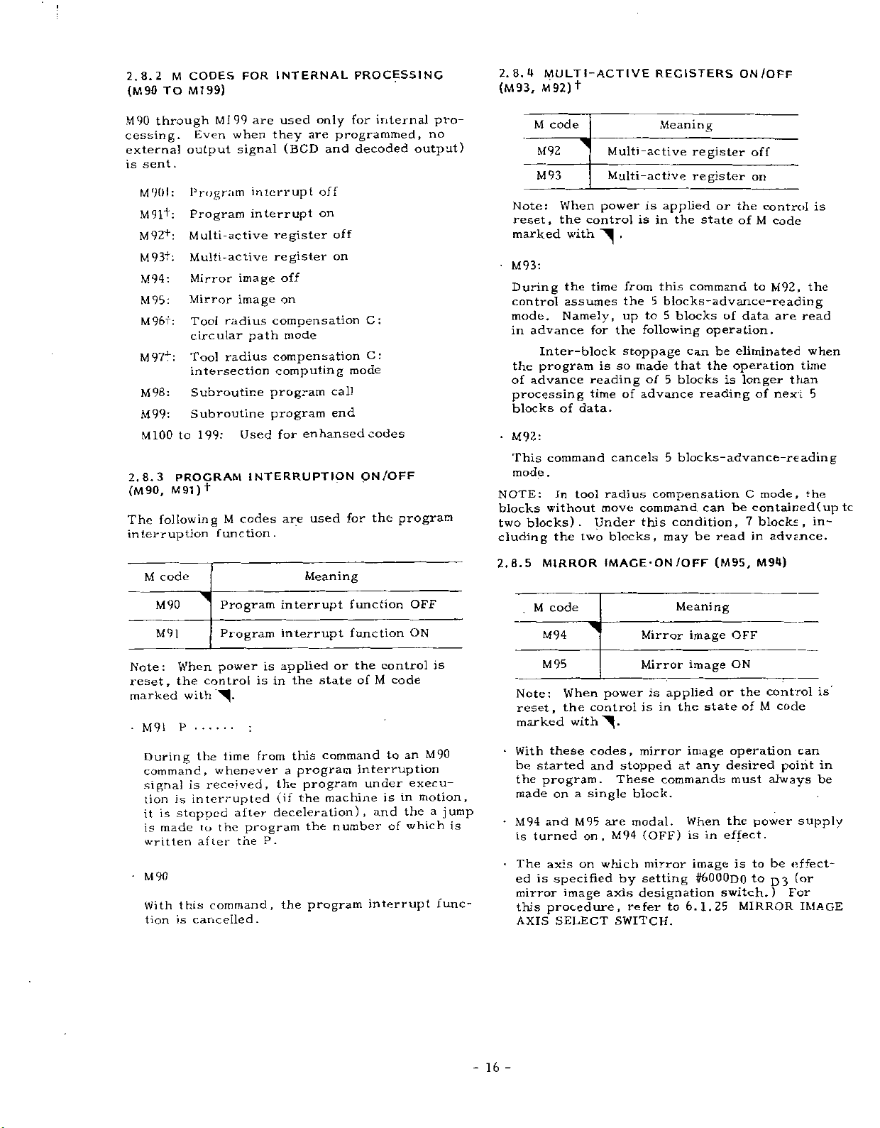
:
2.8.2
(M
90
TO
through
M90
cessing.
externa]
sent.
is
M901:
M91+:
M92+:
M93+:
M94:
M95:
M96+:
M974":
M98:
M99:
M100
2.8.3
(M
90,
following
The
interruption
CODES
M
99)
Ml
Ml
Even
output
Program
Program
Multi-active
Multi-active
Mirror
Mirror
Tool
circular
Tool
intersection
Subroutine
Subroutine
199:
to
PROCRAM
+
M91)
function.
INTERNAL
FOR
are
99
when
they
signal
interrupt
interrupt
register
register
image
image
radius
compensation
path
radius
compensation
computing
program
program
Used
for
INTERRUPTION
codes
M
used
(BCD
off
on
mode
are
only
are
programmed,
and
off
on
off
on
call
end
enhansed
used
PROCESSING
for
internal
decoded
C:
C:
mode
codes
/OFF
ON
the
program
for
pro¬
no
output)
2.8.4
(M
93,
Note:
reset,
marked
M93:
During
control
mode.
in
the
of
processing
blocks
•
M92:
This
mode
NOTE:
blocks
blocks).
two
cluding
MULTI-ACTIVE
M92)
+
M
code
M92
M93
When
the
control
with
time
the
assumes
Namely,
advance
for
Inter-block
program
advance
reading
time
of
data.
command
.
tool
In
without
two
the
Multi-active
Multi-active
power
.
from
the
up
the
stoppage
made
so
is
of
cancels
radius
move
Under
blocks,
REGISTERS
Meaning
register
register
is
applied
is
in
this
5
blocks-advance-reading
5
to
following
5
of
advance
5
compensation
command
condition,
this
may
or
the
state
command
blocks
of
operation.
can
be
the
that
blocks
operation
is
reading
blocks-advance-reading
be
can
be
read
ON/OFF
off
on
the
control
of
M
code
M92,
to
data
are
eliminated
longer
of
next
C
mode,
contained(up
7
blocks,
in
advtnce.
is
the
read
when
time
than
5
the
tc
in¬
M
M90
M91
Note:
reset,
marked
•
M91
During
command,
signal
tion
it
is
written
•
M90
With
tion
code
is
is
made
is
3
When
control
the
with
P
the
received,
is
interrupted
stopped
to
after
this
cancelled.
Program
Program
power
time
whenever
after
program
the
the
command,
interrupt
interrupt
is
applied
in
is
from
a
the
(if
deceleration)
P.
the
Meaning
state
the
this
program
program
the
the
program
function
function
the
or
of
command
interruption
machine
,
number
control
code
M
to
under
is
and
of
interrupt
OFF
ON
an
execu¬
motion,
in
the
which
is
M90
a
func¬
jump
is
2.8.5
•
•
•
M
Note:
reset,
marked
With
be
started
the
made
M94
turned
is
The
is
ed
mirror
this
AXIS
MIRROR
code
M94
M95
When
the
withÿ.
these
program.
a
on
M95
and
on,
on
axis
specified
image
procedure,
SELECT
IMAGE-ON/OFF
Mirror
Mirror
power
control
codes,
and
is
is
mirror
stopped
in
These
are
M94
which
by
axis
block.
modal.
(OFF)
mirror
setting
designation
single
refer
SWITCH.
Meaning
image
image
applied
state
the
image
at
any
commands
When
in
is
image
#6000d0
6.1.25
to
(M95,
OFF
ON
or
operation
desired
must
the
effect.
is
switch.)
M94)
control
the
M
of
always
power
to
be
to
03
MIRROR
code
point
For
is
can
in
be
supply
effect¬
(or
IMAGE
-
-
16
Page 25
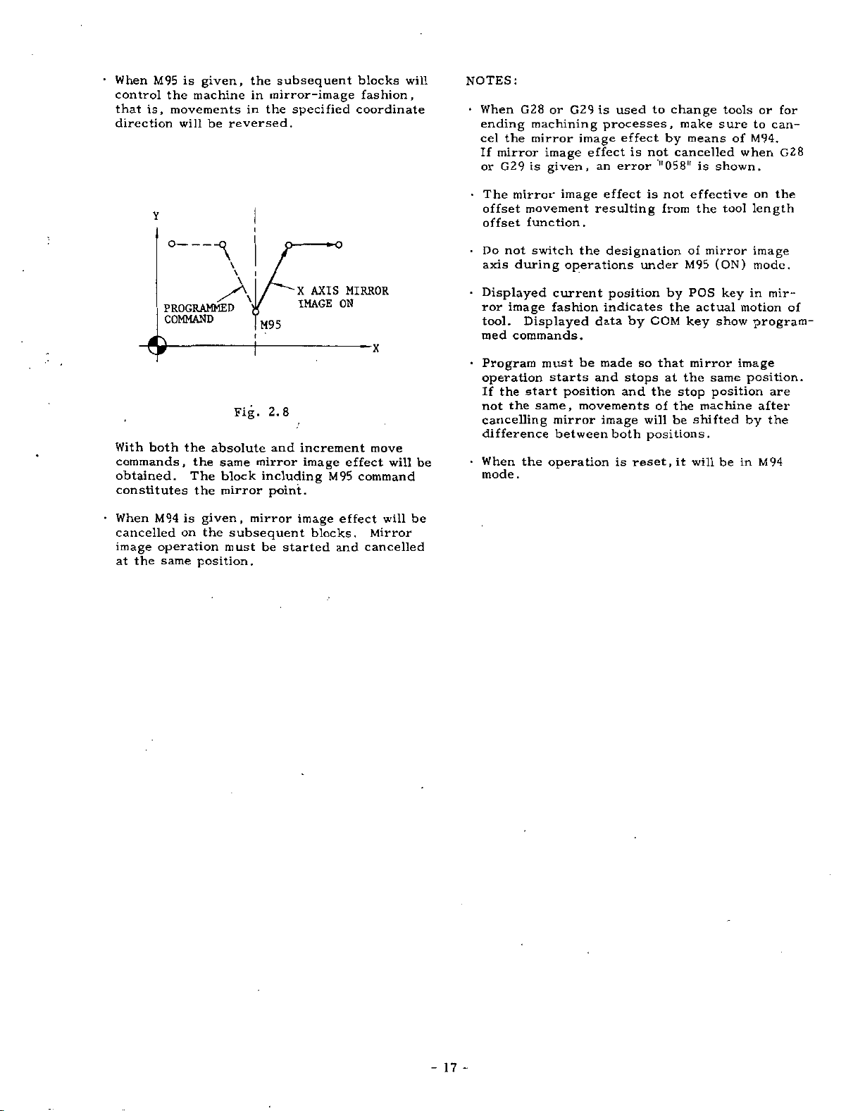
When
control
is,
that
direction
is
M95
the
movements
will
given,
machine
be
the
in
in
reversed.
subsequent
mirror-image
specified
the
blocks
fashion,
coordinate
will
NOTES:
•
When
ending
cel
mirror
If
or
the
G29
G28
or
machining
mirror
image
is
given,
G29
image
is
processes,
effect
an
used
effect
error
make
means
is
tools
sure
of
shown.
to
M94.
when
or
for
can¬
G28
to
change
by
not
is
cancelled
"058"
With
commands,
obtained.
constitutes
•
When
cancelled
image
the
at
Y
PROGRAMMED
COMMAND
both
the
absolute
the
The
the
is
on
given,
the
M94
operation
same
position.
/A
Fig.
same
block
mirror
mirror
subsequent
must
M95
2.8
and
mirror
including
point.
be
started
o
AXIS
X
IMAGE
increment
image
M95
image
blocks.
MIRROR
ON
effect
command
effect
and
move
will
will
Mirror
cancelled
be
be
•
The
offset
offset
Do
axis
•
Displayed
ror
tool.
med
•
Program
operation
the
If
not
cancelling
difference
•
When
mode.
mirror
movement
function.
not
switch
during
image
Displayed
commands.
must
start
same,
the
the
operation
image
the
operations
current
fashion
starts
position
movements
mirror
between
resulting
data
be
and
made
image
effect
is
designation
under
position
indicates
by
so
stops
and
will
both
positions.
is
reset.it
not
from
by
COM
that
at
the
of
the
stop
the
be
effective
the
of
mirror
M95
POS
actual
key
mirror
the
same
position
machine
shifted
will
tool
(ON)
key
show
be
on
length
image
mode.
in
motion
program¬
image
position.
after
by
in
M94
the
mir¬
of
are
the
17
-
-
Page 26
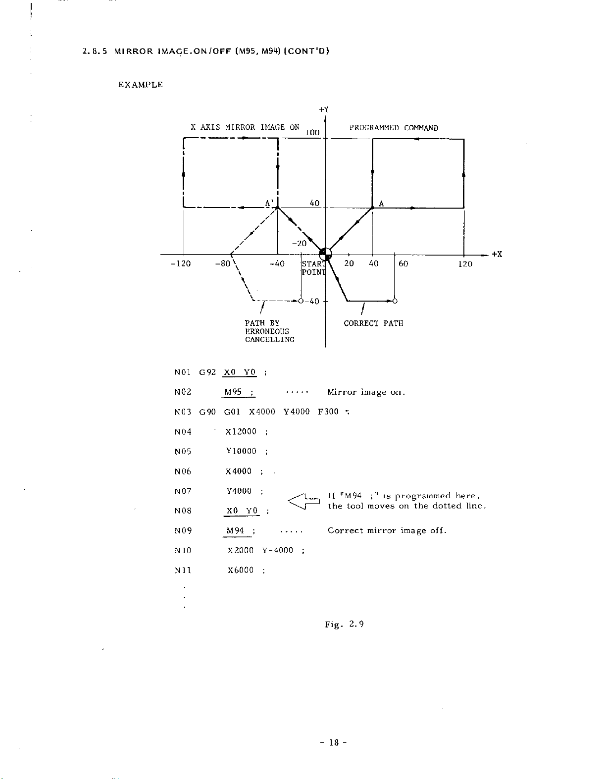
2.8.5
MIRROR
EXAMPLE
IMAGE.
1
X
ON
/OFF
AXIS
100
)
+Y
PROGRAMMED
(M95,
MIRROR
-
M94)
IMAGE
1
(CONT'D
ON
---
COMMAND
-120
NO
N02
N03
N04
N05
N06
N07
N
08
\
-20
-*0-40
Y4000
40
STARl
POINT
F300
--
Mirror
If
the
20
I
CORRECT
image
•;
|TM94
tool
A
40
PATH
;
is
"
moves
60
on.
programmed
on
the
dotted
120
here,
line.
A’
TV
/
/
/
/
£
-80
\
\
-40
\
\
--
T
BY
PATH
ERRONEOUS
CANCELLING
XQ
G
1
92
M95
GO
G90
•
X12000
Y10000
X4000
Y4000
XO
1
YO
;
X4000
YO
;
;
;
;
;
;
N09
10
N
Nil
M94
X2000
X6000
;
4000
Y-
;
Correct
;
Fig.
18
mirror
2.9
-
image
off.
Page 27
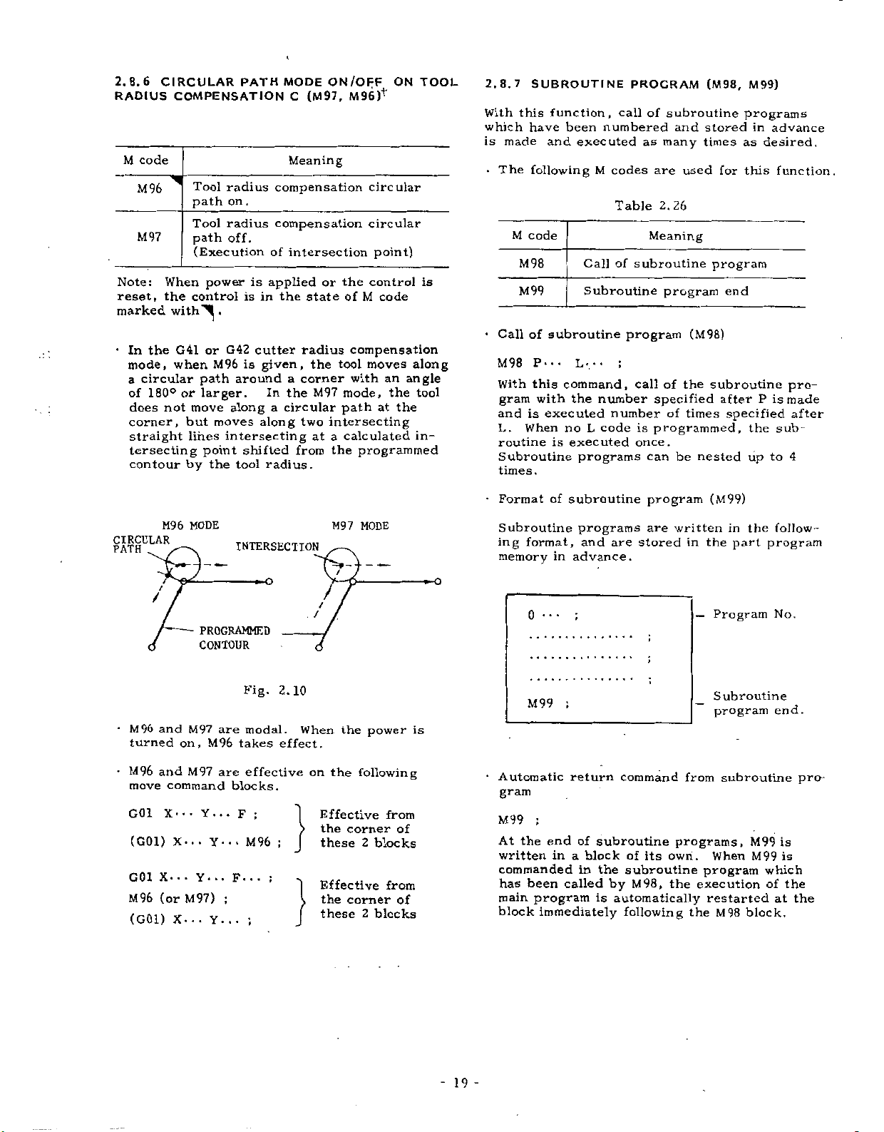
2.8.6
RADIUS
M
code
M96
M97
Note:
reset,
marked
•
In
the
mode,
circular
a
of
180°
does
corner,
straight
tersecting
contour
CIRCULAR
COMPENSATION
Tool
radius
path
on
Tool
radius
off.
path
(Execution
power
When
control
the
withÿ
G41
when
or
.
G42
M96
path
or
larger.
not
move
along
moves
but
lines
intersecting
point
by
the
PATH
.
is
is
in
cutter
is
around
along
shifted
tool
MODE
(M97,
C
Meaning
compensation
compensation
of
intersection
applied
state
the
radius
given,
a
corner
In
the
circular
a
two
from
radius.
ON/OFF
or
the
the
tool
M97
path
intersecting
calculated
at
a
the
M96)+
ON
circular
circular
point)
control
M
of
code
compensation
moves
with
an
mode,
the
the
at
programmed
TOOL
is
along
angle
tool
in¬
2.8.7
With
which
is
made
•
The
M
•
Call
M98
With
gram
and
L.
routine
Subroutine
times.
SUBROUTINE
function,
this
been
have
and
executed
following
code
M98
M99
of
subroutine
P...
Lv
command,
this
with
the
is
executed
When
no
executed
is
call
numbered
M
codes
Table
of
Call
Subroutine
;
number
number
L
code
programs
PROGRAM
of
subroutine
as
many
are
2.26
Meaning
subroutine
program
program
call
of
specified
of
is
programmed,
once.
can
and
used
the
times
be
(M98,
stored
times
program
(M98)
subroutine
nested
M99)
programs
as
for
this
end
after
specified
the
up
in
advance
desired.
P
is
sub¬
to
function.
pro¬
made
after
4
M96
CIRCULAR
PATH
/
/
•
M96
and
turned
•
and
M96
move
G01
X---
(G01)
X.
G01
(or
M96
(G01)
MODE
A
PROGRAMMED
CONTOUR
M97
on,
M96
M97
command
Y...
.
.
X-
Y-
.
•
Y.
•
M97)
.
.
X.
Y.
INTERSECTION
O
Fig.
2.10
are
modal.
takes
effect.
are
effective
blocks.
;
F
M96
•
;
;
;
••
.
F.
;
.
.
f
.
/
When
on
Effective
the
these
Effective
the
these
M97
/
the
the
MODE
power
following
corner
2
blocks
corner
2
blocks
from
of
from
of
•
Format
Subroutine
ing
memory
O
is
•
Automatic
of
format,
0
M99
subroutine
programs
and
in
advance.
;
return
are
command
program
are
stored
written
in
—
from
(M99)
in
the
part
Program
Subroutine
program
subroutine
the
follow¬
program
No.
end.
pro¬
gram
;
M99
end
the
At
written
commanded
has
been
main
program
block
of
in
a
block
in
called
immediately
subroutine
of
the
subroutine
M98,
by
is
automatically
following
its
programs,
own.
program
the
execution
the
When
restarted
M98
M99
M99
which
of
block.
is
is
the
the
at
19
-
Page 28
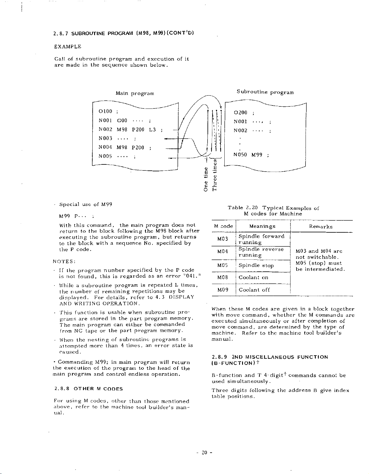
SUBROUTINE
2.8.7
EXAMPLE
Call
of
are
made
subroutine
in
the
PROGRAM
program
sequence
(M98,
and
shown
M99)
execution
below.
(CONT
of
*D}
it
•
Special
M99
With
return
executing
the
to
P
the
NOTES:
•
the
If
not
is
•
While
number
the
displayed.
AND
•
This
grams
The
from
•
When
attempted
caused
•
Commanding
the
execution
main
program
2.8.8
For
using
above,
.
ual
use
P-..
command,
this
the
to
block
code.
program
found,
a
subroutine
WRITING
function
are
program
main
NC
tape
the
nesting
.
OTHER
M
refer
0100
N001
002
N
N003
N
004
N
005
of
M99
;
block
subroutine
the
with
number
this
of
remaining
For
OPERATION.
is
stored
or
more
M99;
of
the
and
M
CODES
codes,
to
the
Main
program
;
GOO
----
P200
M98
;
----
P200
M98
;
----
the
main
program,
specified
is
repetitions
refer
when
part
program
program
to
endless
than
tool
the
No.
subroutine
program
be
those
a
is
program
details,
usable
in
can
the
of
than
in
program
control
other
machine
following
sequence
regarded
the
either
part
subroutine
times,
4
main
_
;
L3
;
program
M98
specified
by
as
an
repeated
4.3
to
commanded
memory.
programs
error
an
will
the
head
operation.
builder's
;
does
block
returns
but
P
the
error
L
be
may
DISPLAY
pro¬
memory.
state
return
of
mentioned
man¬
not
after
by
code
Tl041.n
times,
is
is
the
\
rj
g
o
a
*
<D
CJ
U
x
c
H
O
Table
M
code
MO
3
M04
M05
M08
M09
When
these
with
move
executed
command,
move
machine.
ual
man
2.8.9
(B~FUNCTION)
B-function
simultaneously.
used
Three
positions.
table
Subroutine
0200
N001
N002
N
;
•*
050
M99
2.20
codes
M
Meanings
Spindle
running
Spindle
running
Spindle
Coolant
Coolant
M
codes
command,
simultaneously
Refer
.
2ND
MISCELLANEOUS
and
digits
following
•
i
Typical
forward
reverse
stop
on
off
are
to
+
T
4-digitÿ
program
;
for
Machine
are
given
whether
or
determined
machine
the
the
Examples
M03
not
M05
be
in
the
after
FUNCTION
commands
address
of
Remarks
and
M04
switchable
(stop)
must
intermediated.
block
a
commands
M
completion
the
by
tool
type
builder's
cannot
B
give
are
.
together
are
of
of
be
index
20
-
Page 29
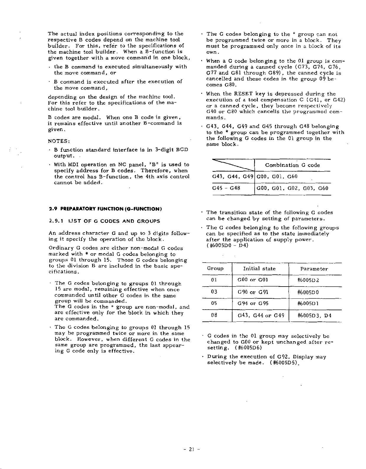
The
actual
respective
builder.
the
machine
given
•
the
B
the
move
•
B
command
move
the
depending
this
For
chine
tool
B
codes
remains
it
.
given
NOTES:
•
B
function
output,
•
With
specify
the
control
cannot
index
B
For
together
command
on
refer
builder.
are
effective
i
MDI
address
be
positions
codes
this,
builder.
tool
with
command,
executed
is
command,
the
the
to
modal.
standard
operation
has
added.
depend
refer
move
a
executed
is
or
design
specifications
When
until
interface
on
B
for
B-function,
corresponding
on
the
to
the
When
command
simultaneously
after
the
of
B
one
another
NC
panel,
codes.
the
machine
specifications
B-function
a
the
machine
code
is
one
in
execution
of
the
is
B-command
in
3-digit
"B"
is
Therefore,
4th
axis
to
tool
tool.
ma¬
given,
used
control
the
of
is
block,
with
of
is
BCD
when
TheGcodes
be
programmed
be
must
own
.
When
a
manded
G77
and
cancelled
comes
When
execution
or
G40orG80
mands.
G43,
to
the
same
G80.
the
a
canned
G44,
the
*
following
block.
belonging
programmed
G
code
during
G81
through
and
these
RESET
of
tool
a
cycle,
which
G49
group
can
G
twice
belonging
canned
a
key
and
codes
to
G44,
G43,
G49
G45-G48
to
or
more
only
G89)
codes
depressed
is
compensation
become
they
cancells
G45
through
be
programmed
the
in
Combination
GOO,
G01
G01,
GOO,
the
once
to
cycle
,
in
the
,
*
group
in
a
a
in
01
the
(G73,
the
canned
the
group
C
respectively
programmed
G48
01
group
G
G60
,
G03,
G02
can
block.
block
group
G74,
during
(G41,
belonging
together
in
code
cycle
09
the
G60
They
of
is
G76,
be¬
the
or
not
its
com¬
is
G42)
com¬
with
PREPARATORY
2.9
2.9.1
An
ing
LIST
address
it
specify
Ordinary
marked
groups
to
cifications.
division
the
•
The
15
G
are
commanded
group
G
The
are
effective
are
commanded.
•
The
G
may
be
block.
same
group
G
ing
OF
character
the
G
codes
with
01
through
codes
modal,
will
codes
or
*
B
belonging
until
be
in
only
codes
code
belonging
programmed
However,
are
onlyiseffective.
FUNCTION
C
CODES
G
operation
are
either
modal
15.
are
included
remaining
other
commanded.
the
*
for
twice
when
programmed,
(G-FUNCTION)
AND
CROUPS
and
up
of
the
non-modal
G
codes
to
G
in
groups
Those
effective
G
codes
group
the
to
are
block
groups
or
more
different
to
3
digits
block.
belonging
codes
the
basic
01
when
the
in
non-modal,
which
in
01
in
G
the
last
G
codes
belonging
through
once
same
through
the
codes
appear¬
follow¬
to
spe¬
and
they
same
in
the
15
The
transition
can
be
G
The
be
can
the
after
(#6005DO-D4)
Group
01
03
05
08
G
codes
changed
setting.
•
During
selectively
changed
codes
specified
application
GOO
G90
G94orG95
G43,
in
to
(#6005D6)
the
state
by
belonging
as
Initial
or
or
G44
the
01
GOO
or
execution
be
made.
of
setting
to
of
state
G01
G91
or
group
kept
the
following
of
the
to
the
state
supply
G49
may
unchanged
G92,
of
(#6005D5).
parameters.
following
immediately
power.
Parameter
#6005D2
#6005D0
#600501
#6005D3,
selectively
after
Display
G
codes
groups
D4
be
re¬
may
2]
-
Page 30
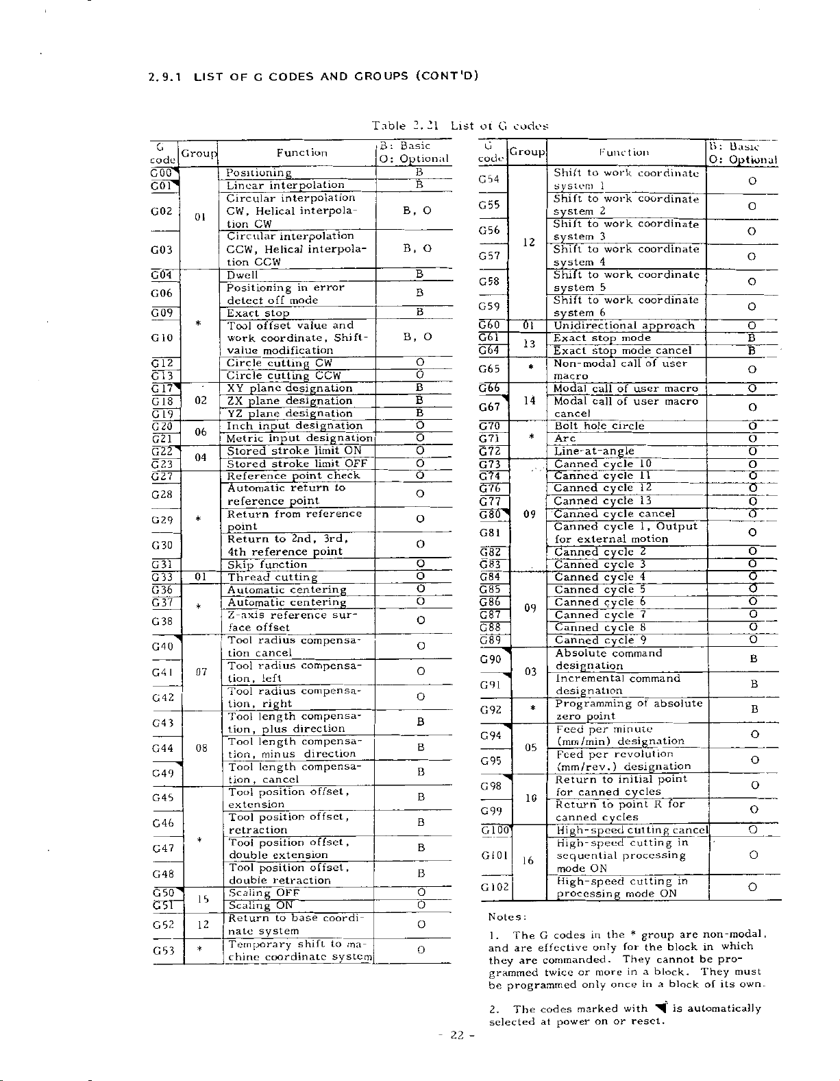
2.9.1
LIST
OF
C
CODES
AND
CROUPS
(CONT'D)
G
code
GOOl
1
GO
G02
G03
G04
G06
G09
10
G
2
1
G
1
G
3
G17ÿ
18
G
19
G
G20
G21
22T
G
C23
G27
G28
G29
G30
G
31
G33
G
36
G37
G
38
G40
G41
G42
G43
G44
G49
G45
G46
G47
G48
GOTÿ
GOT
G
52
G53
Group
01
*
02
06
04
*
01
*
07
08
*
15
12
*
Positioning
Linear
Circular
CW,
Helical
CW
tion
Circular
CCW,
Helical
CCW
tion
Dwell
Positioning
detect
stop
Exact
offset
Tool
coordinate,
work
modification
value
Circle
Circle
plane
XY
plane
ZX
plane
YZ
input
Inch
Metric
Stored
Stored
Reference
Automatic
reference
Return
point
Return
4th
reference
Skip
function
Thread
Automatic
Automatic
Z-axis
offset
face
radius
Tool
cancel
tion
radius
Tool
tion
jleft
radius
Tool
lion,
right
Tool
length
plus
tiun,
Tool
length
tion,
minus
length
Tool
,
cancel
tion
Tool
position
extension
Tool
position
retraction
Tool
position
double
Tool
position
double
Scaling
Scaling
Return
nate
system
Temporary
coordinate
chine
ion
Funct
interpolation
interpolation
interpola¬
interpolation
interpola¬
in
mode
off
value
cutting
cutting
designation
designation
designation
designation
designation
input
stroke
stroke
point
return
point
reference
from
2nd,
to
cutting
centering
centering
reference
compensa¬
compensa¬
compensa-
_
compensa-
direction
compensa¬
direction
compensa-
_
offset,
offset,
offset,
extension
offset,
retraction
OFF
ON
base
to
shift
error
CW
CCW
limit
limit
check
3rd,
point
coordi-
and
Shift-
ON
OFF
to
sur¬
to
ma¬
systemj
Table
B:
O
Basic
:
Optional
B,
B
B,
2.21
B
B
O
,
O
B
B
B
O
O
o
B
B
B
O
O
O
O
O
O
O
O
O
o
O
O
O
O
O
O
B
B
B
B
B
B
B
O
O
O
O
List
22
code
G54
G55
G56
G57
G58
G59
GOT
GOT
GOT
G65
GOT
G72
G73
G74
-
ot
G
G
G67
G70
G71
G76
G77
GOTÿ
G81
G82
G83
G84
G85
GOT
G87
G88
G89
G90
G91
G92
G94
G95
G98
G99
GlOT
G10I
02
1
G
Notes
1.
and
they
grammed
be
2.
selected
codes
Group
Shift
system
Shift
system
Shift
system
12
Shift
system
Shift
system
Shift
system
(5T
Unidirectional
Exact
13
Exact
Non-modal
*
macro
Modal
14
Modal
cancel
Bolt
Arc
*
Line-at-angle
Canned
Canned
Canned
Canned
Canned
09
Canned
for
Canned
Canned
Canned
Canned
Canned
09
Canned
Canned
Canned
Absolute
designation
03
Incremental
designation
Programming
*
zero
Feed
(mm
05
Feed
Return
for
10
Return
canned
sequential
,6
:
G
codes
The
effective
are
commanded.
are
twice
programmed
codes
The
at
power
Kune
to
1
to
2
to
3
to
4
to
5
to
6
stop
stop
call
call
hole
external
point
per
/min)
per
(mm/rev.)
canned
cycles
High-speed
High-speed
ON
mode
High-speed
processing
in
only
or
more
only
marked
on
t
work
work
work
work
work
work
mode
mode
call
of
of
circle
cycle
cycle
cycle
cycle
cycle
cycle
cycle
cycle
cycle
cycle
cycle
cycle
cycle
cycle
command
command
_
minute
designation
revolution
designation
to
initial
cycles
point
to
cutting
cutting
processing
cutting
mode
the
for
They
in
once
with
or
ion
coordinate
coordinate
coordinate
coordinate
coordinate
coordinate
approach
cancel
of
user
user
user
10
11
12
13
cancel
,
Output
1
motion
2
3
4
5
7
8
9
of
absolute
point
_
R
_
ON
group
*
the
cannot
block.
a
a
in
reset.
macro
macro
for
cancel
in
in
are
block
block
automatically
is
B:
O:
Optional
non-modal,
which
in
pro¬
be
They
of
its
Basic
'U
must
own.
O
O
O
O
O
O
O
B
B
O
o
O
O
O
O
O
O
O
o
O
O
O
O
(3
O
O
O
O
B
B
B
O
O
O
O
O
O
O
Page 31

2.9.2
GOO
X---
(where
With
this
fied
position
3
axes
coordinate
does
not
The
rapid
inherent
are
machine
POSITIONING
Y---
B,
A,
a
=
command,
in
rapid
axes'1')
(4
positions
move
along
traverse
the
to
builder's
tool
(GOO,
(at--.)
Z---
C,
simultaneously.
U,
the
is
that
rate
V,
tool
traverse
not
coordinate
for
specified,
machine
manual.
G06)
orW)
is
the
tool.
;
sent
motions
If
respective
Refer
to
any
axis.
the
the
along
of
machine
to
speci¬
the
the
axes
the
NOTE
•
GOO
DETECT
gram
servo
missible
trol.
of
the
•
With
G06,
by
immediately
bution.
commands
ON
advances
pulses
lag
level,
With
workpiece
the
ERROR
the
mode,
this
program
after
position
which
the
to
are
and
this
command,
is
DETECT
the
the
next
decreased
is
machined
advances
completion
tool
means
block
detected
therefore
sharp.
OFF
in
that
only
below
mode
to
of
the
ERROR
the
after
the
the
by
the
commanded
the
next
pulse
pro¬
the
per¬
con¬
corner
block
distri¬
Motions
in
dependent
tool
ant
path
programming
to
care
avoid
interference
EXAMPLE
G01
X4000
X"
Z
GOO
is
a
Error
detect
G06
X-..
With
this
are
initiated
following
•
After
the
with
G06
next
block
(Note)
is
rounded.
G06
is
group,
which
the
each
is
tool
the
.
Y
4
modal
OFF
Y---
command,
as
exceptions.
completion
block,
in
Therefore,
.
a
non
therefore,
and
is
it
programmed.
respective
other,
not
necessarily
positioning
possibility
4000
Y
4
0
z
Fig.
G
code
positioning
Z.-.
the
with
the
the
ERROR
modal
axis
and
Z4000
Rapid
X
Y
Z
2.11
belonging
(at-
same
GOO
a
of
program
the
G
code
it
directions
therefore,
commands,
of
;
4
traverse
axis:
axis:
axis:
(G06)
••)
positioning
command,
the
positioning
DETECT
tool
belonging
is
effective
straight.
and
tool
8
m
/
8
m/min
4
m/min
to
the
;
advances
path
at
the
workpiece
rate
min
01
with
OFF
the
to
only
are
result¬
When
take
X
group.
motions
the
motion
the
to
mode
corner
the
in
in¬
•
-
is
a
tool
axis.
code
F
FzZ
block
the
)
moved
certain
becomes
F100
(C01)
F--.
:
simultane¬
directions
axis
not
does
the
feedrate
are
so
control¬
the
+
Fa2
the
in
either
values
to
2.9.31
(G90,
containing
constitutes
block
;
100
mm/min
RESULTANT
FEEDRATE
(TANGENTIAL
FEEDRATE)
X
result¬
move
,
X
in
with
G91)).
is
spec¬
Y
ab¬
the
.
•
•
2.9.3
G01
where
With
ously
ing
missing
in
in
the
LINEAR
X-..
a
this
in
a
axial
=
the
linear
in
Feedrate
in
the
led
ified
component
that
feedrate.
.F
(where
the
directions
The
end
solute
coordinates
G90orG91
Absolute
F
no
If
G01
an
EXAMPLE
or
error
GO
code
in
1
INTERPOLATION
Y...
,
C,
B,
A
command,
three
motion.
command,
the
direction
is
specified
resultant
y
Fx2
,
Fx
Fy
)
.
can
point
respectively.
/Incremental
is
given
preceding
"030.
"
4000
X
4
Y
Y
4
0
Z...
U,
the
(four+)
of
by
axial
+
Fy2
.
.
•
be
or
in
Programming
in
blocks,
4000
(
a+.
V,
orW
tool
axial
When
the
that
an
directions
feedrate
+
feedrate
are
programmed
incremental
(Refer
the
Z4000
*
2.12
Fig.
(
,
A
feedrates
Y
indicated.
as
and
axis
in
Z)
,
Whore
or
B
the
and
C),
basic
the
the
optional
for
three
rotary
the
axis
axis
4th
same
axis
code,
F
directions
feedrate
a
i
s
rotary
the
(X,
are
-
23
-
Page 32

'I
2.9.3
2.9.4
With
led
LINEAR
Metric
output
Inch
output
Note
CIRCULAR
the
along
F-function
Metric
Inch
Metric
Inch
:
Feedrate
following
specified
the
INTERPOLATION
input
input
input
input
of
linear
INTERPOLATION
commands,
circular
(COT)
F40
F31
F50
F31
4th
tooliscontrol¬
the
pathes
Feedrate
three
as
the
(C02,
(CONT'D)
Table
axes
1
mm
0.1
in
mm
1
in.
0.
I
same
C03)
on
the
in
/min
.
/min
/min
/min
XY
2.
In
basic
as
22
minimum
that
ZX,
,
by
F
command
Feedrate
of
basic
or
theFcode.
YZ
0.
three
plane,
of
2.
54
3937
unit
rotary
1
deg
deg/min
deg
1
deg/min
axes.
at
axes
/min
/min
a
tangential
speed
specified
The
is
as
moving
follows.
G02:
G03:
XY
ZX
YZ
direction
Clockwise
Countei
plane
plane
plane
of
clockwise
—
Y
003
G17
G18
G19
the
XY
(
G
tool
,G02
plane
1
f
l
f
J
7)
1
G02
G03
J
G02
'X
3
I,
GO
f
G02l
IG03J
along
X
X-
Z-
Y-
the
••
•
•
.
-
circle
X
GO
Y-
X-
Z-
3
ZX
(
G
Fig.
•
|
002
plane
8)
1
R.
I-
*•••
K.
2.13
.
-
•
•
J-
I
•
•
•
K
Z
F
•
\
F
•
J
Z
G02
3
GO
Y
plane
YZ
(G19)
24
-
Page 33
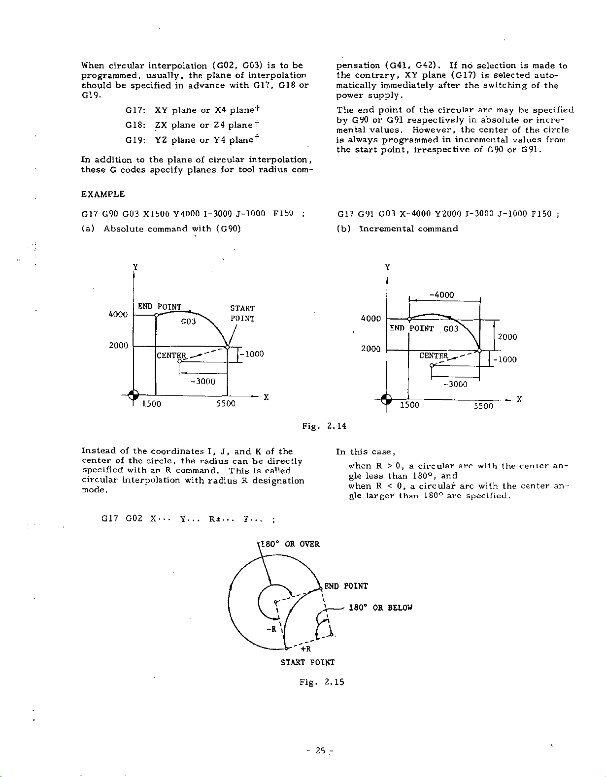
When
circular
programmed,
should
be
G19.
In
addition
G
these
EXAMPLE
specified
G17:
G18:
G19:
to
codes
interpolation
usually,
in
XY
plane
plane
ZX
YZ
plane
plane
the
specify
the
plane
advance
or
or
or
circular
of
planes
(G02,
X4
Z4
4
Y
for
G03)
interpolation
of
with
plane+
planet
planet
interpolation,
tool
G17,
radius
G91
G42)
XY
.
plane
after
of
the
circular
respectively
However,
irrespective
no
If
(G17)
the
in
incremental
selection
the
arc
in
of
is
switching
absolute
center
is
selected
be
may
or
the
of
values
G90orG91.
made
auto¬
of
the
specified
incre¬
circle
from
to
supply.
end
or
values.
(G41,
immediately
point
programmed
point,
to
be
is
G18
or
com-
pensation
the
contrary,
matically
power
The
G90
by
mental
is
always
start
the
G17
G90
(a)
Absolute
Instead
center
specified
circular
mode.
G03
4000
2000
of
the
of
the
with
interpolation
X1500
command
END
POINT
CENTER
1500
coordinates
circle,
an
Y4000
G03
the
R
command.
with
-3000
with
1-3000
(G90)
I,
radius
radius
5500
J,
J-1000
START
POINT
-1000
and
can
This
R
F150
X
K
of
the
be
directly
is
called
designation
;
Fig.
G17
(b)
G03
G91
Incremental
Y
X-4000
command
Y2000
1-3000
J-1000
F150
;
-4000
4000
END
POINT
2000
1500
2.
14
,
case
this
In
0,
R
less
R
larger
>
than
<
0,
than
a
180°,
a
when
gle
when
gle
G03
CENTER-."'
-3000
circular
and
circular
180°
are
5500
arc
arc
specified.
with
with
2000
-1000
the
the
X
center
center
an¬
an¬
G17
G02
X--.
Y...
Ri
.
.
F-..
•
OR
180°
-R
OVER
POINT
END
r
t
y
t
180°
OR
BELOW
&
+R
START
Fig.
POINT
2.15
25
-
Page 34

2.9.4
(CONT'D)
G02(
7
1
G
this
With
repeated
are
interpolation
the
CIRCULAR
G03)
command,
n
X
Z
Y
INTERPOLATION
J--.
I
complete
is
plane
plane
plane
Without
executed
times.
a
a
a
G17
G18
G19
F...
circular
only
Ln
an
002
J
IG03
G02
/
LG03
(C02,
;
interpolations
L
designation,
once.
)
2
j
\
/
G03)
When
a
linear
interpolation
Y
planes
a
planes
•
•
R
••
•
a-
•
. .
.
{
I-
•
J-
•
R-"
/
a-
-
lK'
•
a-
•
I-
K...}
in
(where
F"'
4th
is
addition
a
axis
possible
U,
-
;
option
to
V,
is
the
used,
Xa
XY,
W)
in
the
or
,
YX,
Za
circular
,
and
and
ZY
NOTE:
•
G17
Where
missing
automatically
is
cannot
rotary
Circular
be
can
closed
plete
EXAMPLE
XO
GOO
XO
G02
G02
X-
address
the
in
as
be
performed
axis.
4th
pathes
programmed
circle
;
YO
YO
1
1
'
{
J'
characters
above
selected.
covering
in
can
JO
000
G02
1000
•
on
.
a
also
•
J-
for
command,
Circular
the
two
single
be
F100
.
.
complete
-
.}
*•••
the
axes
including
more
or
block.
programmed.
;
'2000
axis
4th
the
XY
interpolation
quadrants
com¬
A
circle
is
plane
//.
When
ed
ed,
Especially
coordinate
must
2.9.5
circular
A
linear
a
that
in
tion,
helical
o
—
-o
the
end
shown
areas
but
the
when
be
programmed
HELICAL
interpolation
interpolation
plane
and
this
interpolation.
o»
—
CENTER
o~-
Fig.
is
point
above,
tool
values
can
combined
keep
will
compensation
tool
the
of
INTERPOLATION
along
be
executed
The
represented
o
Z
2.17
programmed
no
alarm
on
point
accurately.
certain
on
a
an
interpolation
end
state
rotating.
is
and
(G02,
not
axis
in
synchroniza¬
point
in
the
applied,
the
plane,
included
is
by
creat¬
is
center
G03)
called
is
hatch¬
+
and
When
circular
a
circular
correction
Points
figure
the
0
below
coordinate
path
path
is
are
.
Fig.
not
is
to
due
as
made
commanded
)
16
2.
values
exactly
calculation
shown
end
as
of
below.
the
on
the
errors,
point.
end
point
correct
etc.,
(See
of
the
-
26
Page 35

•
Command
(a)
(b)
(c)
(d)
(e)
(f)
v
Where
W.
and
and
EXAMPLE
If
For
For
For
For
For
For
(f)
(c)
a
no
,
.
format
XY
ZX
YZ
Xa
a
Z
Ya
one
is
4th
they
plane
plane
plane
plane
plane
plane
Z
90,.
axis
are
of
G17
G18
G19
G17
G18
G
the
linear
is
programmed
regarded
19
G02
1
f
G03
J
1
G02
1
J"
lG03j
rG02l
IG03J
JG021
j
LG03
G02T
f
IG03J
rG02l
G03J
\
axes
4th
in
as
equal
POINT
END
X.
Z-..
Y---
X-
Z.
Y-
(d)
to
U,
F-
F-
the
F.
P
F-
F-
F.
••
•
••
as
of
is
.
-
•
..
•
;
feed
address
an
time
as
;
;
the
for
P.
independent
which
can
follows.
length
block.
be
of
desig¬
Z(a)
¥(<>)•••
X(a)'"
.
Z>
X-
(G04)
;
interrupts
length
address
•••
.
.
.
by
.
Y.
•
X-
..
Z.
•
a
•
•
.
..
a
•
•
..
•
a
•
•
V,
or
,
(e),
(a),
(b)
•
«:::
fR-’-
•
J-
•
l
\
(R--’
IK...
[R---
{
..
J.
2.9.6
G04
This
time
Dwell
The
nated
}
}
..
I-
}
•
K-
)
J-
••
I-
K-
DWELL
P---
command
designated
is
programmed
maximum
with
100
/
X
G17
G03
NOTES:
•
The
•
As
long
start
The
-
the
plane
fore,
interpolation
F'
=
•
Tool
only
cular
X0
circular
as
above
and
end
feedrate
of
the
speed
(Length
F
x
radius
to
compensation
the
circular
interpolation.
R
POINT
Y100.
Fig.
arc
points
F
means
circular
(F1)
is
as
(Length
R100.
2.18
should
note
can
interpolation.
in
follows.
covered
path
100
F
(a)
the
=
10
be
be
the
by
of
0+
on
Z90.
within
satisfied,
is
taken
tangential
direction
linear
circular
can
the
Y
F10.
360°.
at
any
speed
There¬
of
interpolation)
path)
be
applied
plane
;
the
linear
of
time.
cir¬
on
Format
P53
value
The
or
metric
EXAMPLE
P2500
G04
Dwell
time:
Two
types
Dwell
when
block
before
pulses
distribution
2.9.7
Exact
-
When
program
pleting
(Note
corners
effective
tained
Dwell
0
-
/inch
of
servo,
of
EXACT
stop
block
a
a
a).
are
.
time
99999.
does
output,
;
2.5
sec.
dwell
the
specified
the
.
STOP
(G09)
containing
advances
block
This
desired.
in
only
999
not
can
dwell
or
in
function
the
(P
programmable
sec
depend
be
value
block
on
dwell
(C09,
to
the
Error
the
G09
block
on
selected
in
is
identified
completion
C61,
G09
next
Detect
used
is
is
in
metric
by
the
C64)
executed,
is
block
when
non-modal,
which
range)
/inch
parameter:
command
by
of
pulse
after
On
mode
sharp
and
con¬
is
it
input
lag
the
com¬
is
-
27
-
Page 36

2.9.7
Exact
-
When
blocks
On
•
Exact
This
G61.
NOTES:
•
In
ceeds
of
ed
plete
command
•
In
ceeds
complete
linear
fore,
are
"Error
•
For
Off
and
EXACT
stop
once
mode
stop
G
the
to
servo
below
distribution
the
to
and
because
rounded
rapid
modes
not
STOP
mode
G6l
will
be
before
mode
command
Error
the
delay
a
permissible
pulses.
G09
and
the
distribution
circular
Detect
traverse
are
the
by
is
completed
proceeding
Detect
next
pulses
G61
next
of
at
the
Off"
controlled
above
(G09,
(G61)
commanded,
cancel
is
for
cancelling
On
block
only
is
limit
of
circular
off
block
of
interpolations,
the
servo
corner.
mode.
,
the
G
C64)
C61,
all
in
(G64)
mode,
found
the
to
after
Error
the
the
to
following
interpolation
modes,
the
immediately
the
pulses
delay,
This
only
Detect
by
Error
codes.
(CONT'D)
the
next
the
program
the
have
program
after
of
and
tool
mode
GOO
following
Detect
block.
effect
pro¬
number
decreas¬
com¬
the
the
ordinary
there¬
pathes
is
called
On
and
G06,
and
of
pro¬
(where
offset
work
a
corresponds
to
be
For
For
For
With
work
2.9.9
This
is
of
movements
block.
•
Format
G12(
Q2
value
coordinate
set
up.
PI---
P2-
-
-
P6---
the
above
coordinate
CIRCLE
a
canned
It
includes
G13)
is
used
designation
to
the
)
G54
G55
G59
command,
CUTTINC
cycle
for
machining
I---
D---
Y-AXIS
to
discriminate
system.
work
corresponds.
system
can
(C12,
includes
the
following
F---
and
a
means
Pn
coordinate
data
of
be
C13J
a
circle
functions.
from
(n
-
any
changed.
+
a
complete
in
to
l
to
system
desired
a
single
too!
set
(t)
up
n
series
2.9.8
With
values
as
TOOL
G10
a
and
follows.
Designation
Normally,
MDI.
.
.
p.
R
and
offset
.
value
When
regarded
When
regarded
•
Changing
Corresponding
work
in
data
Q
10
G
OFFSET
command,
work
tool
On
the
.
.
R.
tool
-
values
G10
is
as
G10
is
as
work
coordinate
advance
2
Pn
correction
coordinate
of
tool
offset
offset
other
(where
;
,
can
value)
be
offset
commanded
absolute
an
commanded
incremental
an
coordinate
G54
to
systems
.
• •
X-
VALUE
values
hand,
P
replaced
in
in
through
•
•
Y-
DESIGNATION
of
system
(G10)
value
written
are
with
a
offset
tool
=
,
programmed
any
by
G90
the
value.
G91
the
value.
system
G59,
set
are
•
Z-
a-
-
offset
tool
can
be
program
number
a
designated
mode,
mode,
f
separate
up
as
•
-
made
in
R
R
setting
(CIO)
by
G10
is
is
•
Designation
G12
With
as
shown
character
(
this
1
G
4
TART
‘QINT
of
3)
I-
command,
below.
R
specifies
rapid
-
©
«D
1
I-(D)
I
Fig.
traverse
R.
•
-
circular
a
Numerals
rapid
2.19
D-
v\
(D
•
-
following
traverse
TOOL
/
section
F-
bore
X-AXIS
;
•
-
is
R
machined
an
address
sections.
28
-
Page 37

Y
Tool
path
•
Automatic
G12(
With
mental)
address
rapid
can
contact
ly.
v:
G13)
this
traverse
move
J
is
calculation
I-.-
command,
is
designated
character
at
rapid
with
the
programmed
Y-AXIS
©
nm
J...
when
J
section
traverse
stock
J:
71
of
D...
by
in
place
within
is
without
CUT
/©
f
0
yk-(p)
I-
rapid
F-..
depth
numerals
rate
calculated
FINISH
TOOL
K
u-
(D)
I
traverse
of
R
which
a
plus
/
©
os
/
;
of
cut
following
,
the
the
without
automatical¬
or
/
Tool
/
/
section
(incre¬
tool
tool
making
minus
Fig.
X
an
2.20
sign.
G12:
G13:
(D)
compensation
G12:
G13:
•
0
0
represents
Clockwise
Counterclockwise
I:
Radius
(incremental
R:
Rapid
(incremental
Tool
D:
Cutting
F:
Commanding
G13)
G12(
With
this
can
be
Commanding
G12(G13)
With
this
spiral
as
the
radius
programmed
before
shown
diagram
-
0)
—
0
.
of
traverse
radius
I
command,
executed
!•••
command,
below.
(D
=
<6)
0
--
;
surface
..
F-
a
along
hole,
simplification,
zero
has
a
must
be
—
tool
sign)
sign)
No.
designation
•
F*
K
Q
a
sake
tool
increment)
<5)
0-
radius
•
bore
circular
of
-<4)~
<D—
—
0--0
---
set
a
(CW)
finished
value
value
compensation
feed
rate
repeated
•
D-
•
L
spiral
D-
finally
For
shows
0).
Q
without
Y
of
value
(CCW)
circle
with
section
with
circle
•
••
L-
•
circular
the
times.
circle
•
as
G12:
Q,
••
K-
the
toolismoved
finishing
the
the
if
(radius
sign.
GK2)<3>0<S>0
NOTES:
Tool
(n
=
circle
START
POINT
rapid
0,
of
1,
circle
7t
traverse
...
2
10)
bore.
l
Fig.
section
pitch
(D)
2.21
for
X-AXIS
TRAVERSE
RAPID
AUTOMATICALLY
CALCULATED
can
be
a
returning
set
at
-yjj--i
semi¬
-
29
RADIUS
5
/
-
A
2,
/
I
2.22
Fig.
Q:
INCREMENT
/
7
7
K
=
X
RADIUS
FINISHED
OF
CIRCLE
Page 38

;
+
2.9.9
CIRCLE
CUTTINC
(C12,
C13)
(CGNT'D)
•
Combined
tion,
Rapid
nation
combination
G12(G13)
NOTES:
•
Circle
•
The
set
by
With
tool
out
sation)
radius
•
the
In
+
direction
use
the-direction
in
respect
2.23,
ever,
sible.
Tool
Z
repeated
traverse
and
cutting
tool
speed
parameter
circle
a
offset
is
use
the
.
compensation
explanation
of
signs
to
signs
cutting
©
/
z
/
:D)
designation
circle
section,
spiral
shown
as
I
-
is
in
cutting
for
G41
of
When
using
X-axis
of
for
Y-axis)
,
of
I
in
©
R-(D)
T-(D)
I
circle
R...
possible
the
#6225.
its
or
above,
I,
J,
of
can
and
R
the
Q>
®\
©_/
rapid
of
and
spiral
repeated
can
below.
(or
only
rapid
command
radius
G42
G12
or
G40.
with
considered.
is
and
K
X-axis
be
(D)
Y-axis
Y
4
START
POINT
©
traverse
circle.
circle
commanded
be
•)
J"
(tool
only
commanded.
K---
••
F-
L-
the
on
traverse
(G12,
compensation
radius
G13,
motions
codes,
D
(symmetrical
are
minus.
direction
. .
section
G13),
cancel
With
sec¬
desig¬
Q--.
XY
plane.
with¬
compen¬
tool
in
proper
motions
with
In
How¬
is
impos¬
in
the
Fig.
the
Fig.
is
path
Tool
C12:
(T>
-
G13:
(D)
represents
compensation
X
Glockwise(CW)
G12:
G13:
Counterclockwise
I:
Radius
R:
Rapid
Tool
D:
(incremental
(incremental
<2)
D
.
of
traverse
radius
-
<3>
set
a
finished
compensation
-
value
value
value
<4)
(CCW)
circle
with
section
with
\i)
-
of
tool
0
Hi)
-
—
radius
0)
KD
sign)
sign)
value
2.23
R-d
If
also
regarded
•
When
radius
tool
specified,
not
compensation
EXAMPLE
•
GOO
G12
GOO
(a)
and
programming
Z-4000
15000
4000
Z
have
I-d
as
an
error.
G12(G13),
compensation
the
tool
.
;
R4000
;
START
POINT
different
number
moves
DIO
%
\
F300
signs,
always
D.
without
;
DIO
1
m
this
specify
If
this
radius
=
is
a
is
10.0mm
•
I,
mand
them
The
traverse
restriction.
with
regarded
J.
K,
are
.
radius
the
Q
R,
effective
of
I
section
When
restriction
as
an
|
R
-
and
finished
R
error.
d
|
L
codes
only
are
values
are
<
I
|
circle
in
the
in
circle
subject
not
in
programmed,
|
d
-
block
the
and
to
the
conformity
cutting
containing
rapid
following
this
is
com¬
-30-
+Y
+X
Fig.
2.24
30
R
40
=
T
50
=
Page 39

.
GOO
G13
GOO
Z-4000;
1-5000
Z4000;
J700
D15
8.0
F300;
TOOL
7.0
D15
=
RADIUS
DEPTH
-8.0
OF
CUT
mm
The
XY
turned
is
2.9.11
(C20,
Unit
of
following
(G17)
plane
on.
INCH/METRIC
+
G21)
G
data
codes
input
is
selected
DESIGNATION
selectively
are
between
metric
when
specified
and
the
BY
inch.
power
G
CODE
by
the
i
I
I
i
42
50
2.9.10
The
tool
plane
radius
PLANE
for
G17/G18/G19.
G17
G
G19
When
the
planes
4th
are
G17
G18
G19
a
med
means
U
move
command
regardless
G18/G19.
example,
For
G
designated,
is
The
command
G17,
compensation
plane
G18
for
G41
or
l
/
c
Fig.
DESIGNATION
making
compensation
XY
18
ZX
YZ
axisÿ
V
17
or
G19:
XY
ZX
YZ
or
of
if
Z-..
motion
making
G42
plane
added.
W
newly
,
AUTOMATICALLY
TRAVERSE
RAPID
2.25
(C17,
is
designated
or
or
or
.
axis
on
Z
radius
possible
interpolation
Xa
Za
Ya
designation
axis.
the
circular
plane
plane
plane
selected,
is
plane
plane
plane
axis
in
each
plane
the
;
is
tool
is
It
is
including
univocally
not
COMPUTED
SECTION
C18,
the
following
plane
plane
plane
can
be
compensation
determined
to
fourth
C19)
and
G
by
program¬
by
G17/
designate
axis.
codes
by
by
These
of
commanded,
are
G
a
block
changed
•
subsequent
•
tool
•
part
part
•
displays
NOTES:
•
When
inch/metric
state
the
plication
#6001
EXAMPLE
ER
CR
01234
G20
•
When
program,
hand.
When
A.
is
tem
Cancel
B.
(
G41
G
G20
G21
codes
of
its
the
afterwards.
offset
of
setting
of
manual
G20
or
of
depends
DO.
;
;
G20/G21
take
work
used,
.
all
to
code
are
programmed
own.
units
programs
values
G21
selection
G20/G21
selection
the
coordinate
return
tool
G48)
Input
Inch
Metric
one
If
of
all
parameters
movements
commanded,
is
is
changed.
the
at
setting
the
on
-Inch
is
following
system
to
base
it
compensation
unit
the
at
these
the
following
the
of
time
by
designation
input
commanded
procedure
coordinate
command.
leading
codes
G
setting
Therefore,
power
parameter
(G54
motions
in
the
before¬
G59)
to
sys¬
end
are
of
ap¬
31
-
Page 40

2.9.11
(C20,
Take
of
A.
B.
The
ly
G20/G21
the
INCH
)
C
21
the
G20/G21
Program
before
In
principle,
tion
nal)
tool
in
the
offset
tool
/MET
(CONT'D)
+
following
selection.
absolute
move
when
used.
is
offset
G20
must
1C
R
procedure
command.
make
current
values
mode
commanded
be
values.
DESIGNATION
after
point
zero
display
the
position
are
processed
G21
the
and
after
for
reset
display
mode.
modifying
G
BY
the
command
axes
all
(exter¬
different¬
CODE
opera¬
2nd
prohibited
The
boundary
specified
The
inside
selectively
of
parameter
X
G22
With
-
this
prohibited
the
check
by
or
be
•
•
Y-
C
point
Upper
command,
area
function
area
of
a
parameter
the
made
setting.
•
Z-
limit
is
the
outside
a
•
•
the
started,
is
2nd
prohibited
setting
of
prohibited
.1
1
D
point
Lower
checking
cleared.
and
the
limit
or
boundary
area
K
of
with
area
by
the
G23
by
i.s
G22.
can
means
2nd
;,
Stored
set
values
15000
2.9.12
function
This
position
entry
for
parameters
hibited
error
an
•
prohibited
1st
The
eter
be
used
function.
point
off¬
STORED
during
into
area
sign
area
is
a
as
are
B
Processing
G20
STROKE
is
for
manual
the
or
by
,
machine
is
displayed.
area
outside
prohibited
substitute
a
Upper
specified
1ST
PROHIBITED
(Inch)
1.5000
checking
prohibited
G22.
operation
the
area.
limit
or
If
area
point
by
in
LIMIT
automatic
the
of
Processing
G21
(C22,
current
the
area
tool
is
specified
Generally,
overtravel
and
A
parameters.
AREA
(Metric)
15.000
operation
specified
enters
stopped
by
lower
(Xa,
A
mm
C23)
tool
a
and
a
param¬
this
checking
limit
Ya,
in
+
by
pro
can
Za)
2ND
PROHIBITED
(I,
D
K)
J,
Where
area
is
AREA
2nd
outside
prohibited
.
C
C
(X,
(X,
Z)
Y,
Z)
Y,
PROHIBITED
/X
AREA
Where
area
is
2nd
inside.
prohibited
2.27
Z
Y
Yb,
Zb)
Fig.
2.26
X
32
-
(Xb,
B
Fig.
Page 41

The
bers
parameter
of
these
numbers
prohibited
and
areas
the
setting
are
as
num¬
follows.
•
The
parameters
the
outside
follows.
The
2nd
also
be
setting
NOTES:
1st
The
specified
•
Boundary
areas.
•
All
the
manual
a
to
reference
the
power
•
the
If
when
this
is
case,
this
the
sotting
rewriteIhe
prohibited
of
#6007DO
"0"
n
ii
j
prohibited
turned
number.
#6001(3
j
"O"
n
II
2
and
overlapping
lines
prohibited
return
supply.
tool
isinthe
prohibited
the
immediately
turn
of
data
area
1st
ited
2nd
ited
the
point
the
prohib¬
area
prohib¬
area
for
the
2nd
on
and
2nd
check;
2nd
check;
2nd
are
areas
to
by
regarded
off
sotting
or
manually.
specifying
prohibited
Meaning
Inside
Outside
area
checking
off
Meaning
prohibited
off
prohibited
on
prohibited
each
included
become
reference
G28
prohibited
area
the
2nd
move
A
point
B
point
C
point
D
point
prohibition
prohibition
with
other.
in
point
after
becomes
as
prohibited
number,
the
tool
the
inside
area
function
the
following
area
area
area
prohibited
the
effective
or
turning
area
effective,
an
error.
and
out
Table
X
#6600
#6606
#6510
2.23
#6601
#6607
#6511
Y
Z
Division
#6602
#6608
Parameter
#6512
Setting
#6513
and
are
as
#6514
If
only
No
axis.
The
selectively
lock
tool
an
alarm
into
in
stored
stored
operation
#6515
the
the
state
prohibited
returning
stroke
stroke
be
used
by
is
limit
limit
the
created
direction.
can
or
disused
setting
by
area,
be
checking
the
the
set
during
of
entry
tool
to
the
function
the
setting
can
4th
machine
a
of
move
may
the
#6001D5.
+
correct
the
after
with
point
;
axes
point
the
command,
and
the
lamp
reference
is
in
the
regarded
and
(Cycle
offset
Cancel
G27.
(C27)
performing
a
and
ends
towards
(4
and
after
is
point.
no
check
reference
lights.
point
performed
reference
the
start
mode,
the
return
program
the
axes’ll
the
check¬
the
as
an
auto¬
tool
at
If
is
in
the
can
2.9.13
This
of
a
cycle
which
the
G27
With
specified
simultaneously
arrival
ed
any
can
be
tool
made
If
point,
If
after
return
a
at
the
on
of
time
In
area
by
either
of
the
all
further,
point
error
matic
lamp
If
tool
offset
function
the
tool
starts
reference
X---
this
for
of
does
in
the
point
tool
the
the
even
(alarm
operation
goes
G27
return
mode
REFERENCE
to
the
of
operation
at
Y-.-
command,
position
the
at
the
conformity
the
axes
not
move
that
axis.
is
the
reference
is
but
correctly
automatic
if
in
axes,
241
off.)
is
commanded
point
when
is
for
reference
the
point.
Z---
along
but
specified
is
omitted
in
in
conformity
the
axis,
one
244
-
is
interrupted.
is
commanding
POINT
CHECK
checking
point
accordance
in
reference
(a+-
•
•
the
tool
moves
the
three
independently,
point,
to
the
reference
in
axis
that
return
point
the
in
operation
is
this
not
is
tool
display),
the
in
also
tool
offset.
)
the
with
-
-
33
Page 42

2.9.13
Reference
relative
the
by
G28
by
Refer
RETURN
be
applied
formity
(Mirror
M94
2.9.14
POINT
G28
X-
With
this
reference
specified
stops
cally
The
tool
axesÿ)
direction
struction
EXAMPLE
X-
G28
Z
POSITIONING
Z
4
"Return
series
point.
ence
NOTES:
•
G28
If
sation
this
•
If
G28
(M95),
REFERENCE
point
the
to
manual
automatic
6.1.15
to
SWITCH.
to
the
errors,
image
AUTOMATIC
(C28)
t
..
•
Y-
command,
point.
points
the
at
moves
However,
.
of
the
is
omitted.
..
of
is
Y*
V
d
START
POINT
Y
reference
to
motions
commanded
is
mode
regarded
commanded
is
this
•
POINT
as
meant
machine
reference
reference
MANUAL
The
G27
command.
clear
the
off)
before
RETURN
.
(a+.
2-
• •
the
tool
The
in
rapid
reference
simultaneously
tool
the
for
axis
•
•
Z-
•
sj
X.
\
!
AXIS
Y
Fig.
point"
the
as
in
(G41,
constitutes
G42)
an
as
in
CHECK
is
point
a
the
return
return
image
To
image
here
which
to
point
REFERENCE
mirror
mirror
commanding
TO
;
•
is
moves
traverse,
sent
towards
tool
point.
in
up
not
will
which
coordinate
a
REFERENCE
4
j
RETURN
ZERO
INTERIM
POSITIONING
DECELERATION
2.28
manual
the
or
input
the
an
TO
involves
return
tool
a
in
error
Mirror
input
canned
(C27)+
fixed
tool
(CONT'D)
point
returns
motion
motion.
POINT
function
non-con¬
avoid
mode
G27.
REFERENCE
to
back
the
the
and
automati¬
3
axes
to
move
Z
DECELERATION
ZERO
AXIS
the
in
in¬
REFERENCE
POINT
LS
same
the
refer¬
to
radius
compen¬
cycle,
"024.”
Image
error
mode
”058."
or
can
with
(4
POINT
LS
*
The
tool
by
led
commanding
position
succeeding
low.
A.
When
incremental
Tool
value
offset
When
B.
absolute
Tool
fied
C.
When
G28
By
set
ceeding
item
*
When
the
for
supply,
Refer
ENCE
Return
addition
In
Reference
Reference
the
control.
quence
*
After
,
the
B
point
shorter
reference
the
all
*
With
Point,”
the
reference
•
The
rapid
becomes
returned
axes
the
turning
•
Rapid
fective
are
not
Where
given
when
ence
moves
erse
axis
turns
return
4
the
position
G28.
offset
Caro
should
the
moves
from
is
the
moves
by
G29
:
G29
interim
A
and
returning
first
pay
6.2.1
to
POINT+.
to
reference
to
Point,
Point1'
as
is
follows.
positioning
tool
in
rapid
than
in
axes.
the
’’Rapid
point
traverse
possible
once
by
manual
traverse
only
changed
a
4th
for
the
the
tool
in
point
to
the
return
is
included
the
to
mode,
have
axes
Make
G28.
mode,
program
succeeding
mode:
by
the
not
succeeding
mode:
to
absolute
is
command,
positioning
motion
B
the
time
attention
MANUAL
the
above
it
function
With
this
directly
traverse.
that
which
Traverse
B
may
point
to
operation
on
of
return
with
axis
4th
has
the
reference
mode.
in
reference
unless
been
offset
it
a
If
G28
the
becomes
be
taken.
the
reference
effective.
the
value
given
is
.
tool
after
point
ii
Rapid
function,
an
at
moves
with
deceleration
not
return
return
only
reference
the
the
G28.
it.
by
used,
is
axis
been
X,
Y,
If
the
the
completed.
command
to
point
is
given
tool
as
program
amount
point.
program
position
and
immediately
the
tool
point
made
according
to
the
turning
to
the
tool
RETURN
in
rapid
n
Automatic
Traverse
be
may
interim
to
The
the
ordinary
Return
necessarily
possible
to
the
after
or
by
to
reference
supply.
power
Manual
when
a
in
G28
returned
Z
and
in
point
a
command
command,
in
point
return
is
cancel
in
motion
described
is
of
incremental
is
which
tool
moves
and
reference
the
on
position.
TO
traverse
Return
incorporated
the
positioning
reference
the
returning
LSs
to
reference
tool
point
G28,
return
no
command,
to
axes,
the
for
the
the
motions
not
cancel¬
it
before
the
by
the
made
The
made
is
speci¬
offset
after
the
to
the
the
to
the
power
REFER¬
Return
motion
time
return
are
used
Reference
be
within
area.
point
has
been
in
all
following
point
motions
command
refer¬
the
the
rapid
the
tool
ordinary
in
tool
tool
value.
suc-
point
to
se¬
is
and
tool
trav¬
4th
re¬
be¬
in
in
off¬
to
point
to
the
ef¬
is
all
the
the
in
is
in
34
-
Page 43

2.9.15
RETURN
FROM
REFERENCE
ZERO
(G29)
+
EXAMPLE
2
This
code
position
matic
is
after
return
path.
G28
Y--.
Point
Y--.
G29
Point
Doÿ
6
A
When
consider
program.
the
G29
is
the
instruction
tool
ing
to
Movement
id
to
reference
of
traverse
(simultaneously
an
axis
omitted,
If
nal
creates
for
G28
is
coordinates
is
the
programmed
used
return
to
reference
Z...
B
Z--.
D
(REFERENCE
l
i
B
\
!
/
programmed,
distance
Particularly
used,
is
the
original
zero.
C
rate
simultaneously
four
which
tool
of
effective
to
return
to
reference
Point
(Reference
Point
RETURN
TV
INTERIM
POINT
Figl
2.29
between
thisiseffective
position,
B
and
of
axes"!-)
a
coordinate
will
not
a
number
B
point
for
the
the
tool
zero
zero,
along
A
•+
C
POINT)
ZERO
REFERENCE
TO
POSITIONING
is
not
it
when
necessary
point
an
after
+
B
D
is
along
by
G29.
instruction
move.
times,
of
which
move
the
of
original
its
to
auto¬
by
same
the
-*ÿ
C
B
point)
zero
-*•
B
D
ZERO
and
B
incremental
for
return¬
returning
made
at
three
However,
the
G28
last
G29.
C
axes
was
to
in
rap¬
fi¬
G91
G28
G28
M06
G29
f\
/
/
/
20
B
;
Z---
X2000
;
X4000
\
40
;
Y4000
/ÿ
\
Y-4000
Fig.
;
;
2.30
(REFERENCE
+Y
ZERO)
+X
N
N
N
N34
N35
o
31
32
33
A
NOTES:
•
An
input
error
medintool
G42)
G76
•
An
without
turned
•
In
ming
in
offset
point
point
during
or
,
G77,
input
execution
on.
principle,
G28
also
is
will
B
B1
.
G81
error
or
radius
cancel
G29.
effective,
also
"024"
compensation
canned
G89)
to
"059"
of
If
offset,
be
occurs
cycle
.
occurs
G28
tool
they
after
offset
are
interim
and
if
G29
mode
mode
if
G29
the
before
programmed
positioning
the
is
program¬
(G41,
(G73,
is
given
control
program¬
tool
G74,
is
when
passes
EXAMPLE
N
G90
21
22
G28
N
N23
G28
N
24
G29
1
;
Z1000
X3000
X-4000
Equal
the
blocks
(In
two
to
the
Y2000
;
Y-5000
case
;
GOO
GOO
of
absolute
Interim
coordinates
X
(0,
(3000,
;
3000Y2000
X
X-4000
Y
2000,
Y-5000
input)
point
1000)
2000,
Z
1000)
;
35
D'
o—~
'
(REFERENCE
/
/
/
//
B'
/
/
6
A
OFFSET
(INTERIM
POINT)
Fig.
2.31
AMOUNT
POSITIONING
ZERO
POINT)
-
Page 44

2.9.15
ICONT'D)
•
An
input
ing
•
The
taken
be
G28
(1)
(2)
(3)
RETURN
mirror
following
does
The
G28
•
Setup
Machine
•
Manual
G28
following
cancels
from
G28
operation
FROM
error
image
command
because
not
meet
following
and
G29
of
and
G29
mirror
the
starting
and
G29
"058"
(M95)
interim
with
operations
commands.
absolute
lock
operation
are
the
block
are
Manual
at
REFERENCE
occurs
.
or
operation
positioning
that
zero
at
Manual
comrTianded
containing
at
image
point
commanded
Absolute
of
if
the
of
G29
G29.
are
(G92,
mirror
ZERO
is
must
point
made
ORG
Absolute
the
in
M94
different
after
Off.
(G29)
given
between
which
image.
manual
dur¬
not
B
key)
Off
blocks
point
+
of
2.9.17
X--.
G31
With
this
is
commanded.
under
skip
rupted
to
signal
to
0.5
EXAMPLE
N
N200
the
process
m
100
the
signal
next
is
sec.
G90
G01
SKIP
FUNCTION
Y-..
command,
command
is
block.
inputted
the
G31
inputted,
signal,
immediately,
G31
X80.0
• •
Z
a
During
of
From
to
is
non-modal.
X100.0
Y15.0
•
special
and
the
delay
F---
the
this
the
+
(G31)
;
linear
interpolation
program,
interpolation
the
program
the
moment
time
the
time
Y50.0
;
interpolation
that
control
is
less
;
movement
whenever
is
advances
a.
start
than
a
inter¬
skip
2.9.16
RETURN
30
Pn
G
(where
this
With
positioning
terim
2nd,
3rd
2nd
P2:
P3:
P4:
any
If
ted
in
the
in
reference
Each
(#66
eters
EXAMPLE
G30
P3
NOTES:
•
Three
2.9.14
POINT
When
moves
of
interim
However
on
ed
2ND,
30)
(G
X.
•
•
P2,
Pn
=
command,
4th
or
reference
reference
3rd
reference
4th
of
axis
command,
the
direction
to
12
30
X
items
AUTOMATIC
(G28)+
is
G29
the
to
positioning
the
the
axis
3RD
AND
t
•
•
Y-
P4)
P3,
the
point,
reference
point
point
point
the
coordinate
the
of
that
point
#6629)
;
Y50
except
apply
commanded
designated
interim
designated
4TH
•
Z-
-
tool
and
tool
axis.
specified
is
before
•
•
The
3rd
moving
directions
last
the
RETURN
G30
to
after
point
positioning
REFERENCE
(a+-
first
then,
point.
When
,
the
the
point.
instruction
remains
hand.
tool
reference
one
in
G30,
point
designated
G30.
by
•)
;
moves
moves
P
tool
2nd
the
by
returns
the
in
.
NOTES
in
REFERENCE
TO
same
the
G29
by
point
POINT
to
an
the
to
omitted,
is
moves
reference
omit¬
is
motionless
param¬
to
point
X
and
manner.
tool
the
way
by
by
renew¬
is
in¬
the
of
G30.
SKIP
SIGNAL
INPUTTED
to
Y
(50,
When
being
block,
the
Feedrate
tively
specified
•
To
be
grams.
•
To
be
When
a
values
parameter
HERE
20)
G31
block
inputted,
of
one
by
by
specified
set
skip
the
at
IS
and
the
of
parameter
in
signal
moment
data.
is
executed
the
the
alarm
tool
the
by
advance
is
Fig.
machine
is
set
following
#601
F
similar
by
inputted,
are
(100,
i
i
___
_
i
o
15)
(80,
2.32
without
stops
"087"
code
G31
for
two
9D4.
to
parameter
the
automatically
50)
__
SIGNAL
skip
the
end
displayed.
selec¬
pro¬
stored
MOTION
WITHOUT
signal
of
as
as
ACTUAL
PATH
MOTION
SKIP
a
at
is
blocks
methods
ordinary
#6232.
coordinate
-
-
36
Page 45

#6552
#6553
#6554
#6555
These
macros.
user
When
cution
moves
2.9.18
Provided
dle
pulse
a
and
threads
G33
With
this
Z
direction
Lead
•
••
storing
•
•
storing
•
storing
•••
storing
be
can
data
a
signal
skip
G31
of
on
by
to
THREADCUTTING
that
the
next
the
generator
synchronous
can
be
cut
Z...
F-..
command,
a
lead
at
is
range
Metric
shown
i
X
Y
Z
4th
treated
not
is
setting
block
machine
generating
feed
with
;
threadcutting
of
below.
coordinate
coordinate
coordinate
coordinate
as
given
(
#6004DO)
automatically.
(C33)
is
function
this
F.
Range
-
0.01
coordinate
in
spite
+
equipped
reference
(G95)
function.
is
of
99.
99
value
value
value
value
,
the
made
lead
mm
data
the
program
with
pulses,
screw
in
in
exe¬
a
spin¬
the
2.9.19
(C36,
With
the
sensor
G36
With
(or
sensor
gives
the
with
returns
G37
With
(or
sensor
gives
turns
D
where
contact
AUTOMATIC
C371
function,
this
center
.
..(or
I-
this
Y)
direction
makes
a
start
the
I*
•
this
)
Y
makes
a
to
a
=
b
+
line
J-..)
command,
contact
point
function
to
the
.
(
J'
or
•
command,
direction
contact
start
the
b
2
distance
=
point.
the
of
contact
signal.
to
start
•
•
contact
signal.
CENTERING
spindle
the
machined
F-..
the
at
speed
with
the
contact
G37.
of
point
)
F...
•
the
at
speed
with
point
between
;
spindle
F
the
The
Then,
in
;
spindle
F
the
Then,
in
rapid
FUNCTION
is
aligned
bore,
moves
until
workpiece
distance
point
rapid
moves
until
workpiece
the
G37
with
the
is
the
traverse.
the
spindle
traverse.
start
with
a
the
in
touch
"a"
stored
spindle
the
in
touch
point
touch
X
and
from
X
and
re¬
to
Inch
However,
from
tion
F(mm/rev)
NOTES:
•
G33
may
simultaneously
In
this
which
lead
specified
•
G33
is
During
•
mode
change
is
also
at
100%.
G33
can
mode.
mode,
G33
can
compensation
causes
•
Threadcutting
4
If
axes
mand,
lead
is
the
spindle
x
S(rpm)
be
programmed
case,
the
longest
G
code
a
a
threadcutting
ineffective,
only
it
is
If
causes
it
not
be
an
alarm
are
an
alarm
subject
S
for
as
the
tool
distance
F.
by
in
the
are
impossible.
and
be
commanded
commanded
alarm.
an
programmed
C
mode.
.
command
included
is
caused.
0.001
-
the
to
speed.
24000(mm/min)
with
example
moves
is
01
group.
operation,
the
feedrate
in
If
it
is
can
in
a
threadcutting
3.936
following
a
clamp
two
in
G33YyZzFf
along
specified
Feedrate
the
in
the
G94
in
the
commanded,
not
include
inches
or
or
more
the
feedhold
is
G95
(mm
tool
restric¬
value
axes
axis
the
at
override
locked
(mm
/min)
radius
4
com¬
for
and
/rev)
it
axes
I(J)
I'(J')
¥
2.33
is
specified
I'
this
mode
treated
a
G36
value)
obtained
(or
J'),
together
constitutes
or
J
X
X
x
X
X
/
during
incremental
this
:
in
the
in
a
canned
an
as
error
WORKPIECE
the
consti¬
a
in
error.
and
tool
"
11
.
X
X
X
L
X
x
2
,.
/
NOTES:
•
When
movement
distances
tutes
When
block
•
When
radius
cycle,
C
=
—
(I,
J,
no
an
and
I
of
G36
compensation
this
G37
a-b
2
,
I'
contact
through
(or
I
error.
J
G36
or
command
J'
J)
are
or
G37
~T
CENTER
=
Fig.
G37,
Incremental
signal
the
and
programmed
is
commanded
C
is
.
37
Page 46

2.9.19
(C36,
G37)+
EXAMPLE
M06
GOO
Z.
AUTOMATIC
(CONT'D)
Automatic
A:
;
T
10
•Y•
X
-
••
CENTERING
bore
Selection
Positioning
to
axes
Motion
measurable
FUNCTION
centering
of
virtual
in
Z
touch
in
X
center
direction
position
and
sensor
Y
to
EXAMPLE
M06
GOO
G01
(J)
Z-z
©
T10
X
Xr
;
B:
•
•
;
Y
;
Automatic
..
;
•
•
•
outer
Selection
.
Positioning
axes
Motion
radius
Motion
measurable
diameter
of
to
virtual
through
r
in
in
Z
touch
in
X
and
center
virtual
X
direction
direction
position
sensor
Y
to
(I)
©
(3)
@
©
G91
G36
X-2r
G37
Xr
Yr
G36
Y-2r
37
G
Yr
G92
virtual
X
direction
centering
virtual
in
X
2r
centering
of
centering
automatically
(0,0)
direc¬
center¬
point
(1)
(2)
as
point
(3)
(D
(D
(5)
©
(8)
®
G36
Zz
X-2r
Z-z
G37
Zz
Xr
Yr
Yr
G92
I-i
;
;
Ii
;
;
;
;
X0
•
....
;
;
;
Y0
Automatic
in
Retraction
Motion
diameter-2r
tion
Motion
measurable
Automatic
in
Retraction
Completion
in
Similar
>
ing
Setting
obtained
the
X
direction
through
in
X
direction
X
direction
automatic
in
Y
coordinate
centering
in
in
Z
direction
position
centering
in
of
direction
the
automatically
center
Z
Z
centering
;
F-
direction
virtual
X
direc¬
direction
center-
point
(0,0)
(1)
to
(2)
as
point
Ii
Xr
;
Motion
radius
;
•
•
F
-
;
Automatic
in
Motion
direction
X
through
r
in
through
diameter-
tion
;
I-i
;
;
;
Jj
;
Automatic
direction
X
in
Completion
direction
X
in
Similar
in
ing
Y
automatic
direction
J-j;
;
X0
Z0
;
Setting
obtained
the
the
center
coordinate
,R
CENTER
CD
©
Y
X
R
Note
<
:
r
is
assumed
Fig.
in
2.34
the
/
X
WORKPIECE
/
program.
38
-
Z
©;
Note:
-
/
/
assumed
Fig.
—6
D
—
/
T~ry
/
2.
;
7
7
WORKPIECE
0)
X
R
r
is
>
in
35
/
XY
CD
(!)
7
R
TABLE
the
—V
3
u)
program.
j©
Page 47

2.9.20
(C
38)
+
Z-AXIS
REFERENCE
SURFACE
OFFSET
With
rection
sion
sensor.
•
G38
With
Z
direction
touch
d
through
value
the
function,
this
automatically
relative
K-
this
sensor
k
-
=
specified
start
Z
to
a
.
•
•
F.
•
command,
a
at
gives
calculated,
is
g
d
in
g
-
point
g
k
Y77777777777
d
,k:
INCREMENTAL
the
for
reference
;
the
speed
out
rapid
K
by
to
the
START
POINT
tool
is
obtaining
spindle
F,
and
a
contact
and
traverse,
and
g
contact
f
I
l
DISTANCE
offset
surface,
the
is
accurate
moves
stops
signal.
spindle
wherekis
the
distance
point.
d
g-d
in
with
the
in
when
Z
dimen¬
a
touch
the
the
Then,
returns
di¬
a
from
2.9.21
(G40,
It
is
to
cause
Store
offset
gram
tool
1.
k
TOOL
C42)
C41,
possible
automatic
offset
the
value
the
tool
radius
value
Designation
of
D
code
RADIUS
+
to
specify
value
memory
offset
by
of
?
i
i
?
G)i
I
i
f
©
WORKPIECE
2.37
Fig.
COMPENSATION
the
path
tool
(tool
in
advance
number
D
code
a
compensation
d
radius
offset
radius
by
correspond
the
in
direction
of
the
this
by
value)
MDI
program.
C
and
tool
value.
the
in
,
and
pro¬
to
the
and
NOTES:
•
If
contact
no
el
through
an
error
•
.When
C
mode,
as
an
EXAMPLE
i
M06
(T)
G91
G38
©
Zz
;
(3)
G92
G38
error
Til
GOO
K-k
Z0
"087"
is
or
;
Z-z
F
;
the
in
Fig.
signal
specified
is
caused.
commanded
a
canned
"024.
"
;
-
•
•
;
2.36
is
received
incremental
in
cycle,
Selection
Approach
,
ing
point
Z
reference
compensation
Return
position
direction
Setting
origin
the
at
tool
this
to
in
of
during
of
to
in
the
Z
this
the
distance
compensation
is
regarded
touch
the
measur-
Z
direction
surface
offset
Z
the
coordinate
point
trav¬
sensor
C
Tool
radius
G41
with
and
G41
offset
G
code
G40
G41
ment.
G
code
k,
G42
Note:
When
,
G42
with
of
Group
07
07
07
the
compensation
and
G42
indicate
respect
radius
tool
Cancellation
compensation
Tool
C,
Tool
C,
power
cancelled
is
the
to
left
right
is
radius
is
directions
the
direction
compensation
Meaning
compensation
radius
turned
compensation
programmed
by
G40.
of
of
C
of
tool
radius
C
on,
G40
tool
move¬
is
effective.
Note
that
the
(right,
when
offset
ative.
the
ing
will
the
memory
block
block.
be
left)
sign
Make
containing
If
regarded
directions
indicated
of
the
designated
sure
D00
as
above
tool
to
designate
G41,
commanded,
is
"O."
of
compensation
are
radius
a
by
G42
reversed
value
D
code
a
D
or
in
tool
code
a
the
in
neg¬
is
in
preced¬
radius
-
-
39
Page 48

2.9.21
TOOL
RADIUS
COMPENSATION
C
(C40,
C41
C42)+
,
(CONT'D)
PROGRAMMING
Switching
in
given
2.
Designation
The
is
They
(G17)
on
G
TOOL.
the
plane
made
.
G
code
G
17
G
18
G19
are
(LEFT)
G41
Fig.
between
compensation
in
item5below.
of
which
in
designated
is
G
codes
in
effect
is
codes
for
Group
D
G42
2.38
and
G41
mode.
compensating
tool
by
02
of
the
at
designation
02
02
02
(RIGHT)
radius
G17,
group.
time
G42
can
Details
plane
compensation
G18,
The
power
planes
of
Meaning
XY
plane
ZX
plane
YZ
plane
be
will
G19.
is
XY
made
be
plane
turned
EXAMPLE
(a)
G17
G41(
Y
(b)
G17
G41(G42)
G02
A
G01
G42)
X-
G01
X--.
G42
F-.-
D--.
TOOL,
X
F-
••
D--.
Y---
;
X-..
G40
G41
.V-V
PROGRAMMED
X...
J---
Y-..
___
-
PATH
••
•
Y
:
;
3.
Note
Make
is
sure
When
:
designation
G42
nation
It
sation
Method
When
to
to
normal
immediately
instruction
G41(G42)
value
a
or
error
other
in
or
cannot
not
is
in
of
G41(G42)
an
offset
the
radius.
line
only.
movement,
G01
for
(alarm
than
the
effective.
to
designate
in
a
preceding
be
possible
a
plane
entry
position
at
after
is
,
movement
Because
it
G
a
code
GOO,
power
same
the
is
The
the
block.
in
made
to
apply
including
compensation
into
programmed,
with
offset
start
G41(G42)
programmed
is
G41(G42)
is
necessary
in
code
"026)
is
G01
turned
is
G
a
code
as
block
Plane
compensation
a
tool
radius
the
distance
the
position
of
point
If
.
in
the
made
by
to
group
A.
occurs
programmed.
on,
G17
for
plane
of
that
desig¬
compen¬
mode
the
is
the
no
coordinate
axis+.
tool
equal
on
block
fourth
block
the
offset
accompanies
program
An
input
G
a
if
code
G41,
mode.
moves
the
of
GOO
G4
TOOL,
\
\
Fig.
G40
G41
>
v:
V
CENTER
2.39
-
40
Page 49

EXAMPLE
B
(c)
GOl
G17
G41(G42)
X...
G02
X---
F---
D---
Y---
Y
TOOL,
\
G42
••
G40
s
/
;
\
;
J---
G41
\
CENTER
;
\_J
•V
(d)
TOOL,
X
2.40
Fig.
G01
G
17
G41(G42)
X--
G02
G41
CENTER
F
D.
X'"'/
f-
L
>'
G42
Y-
••
.
•
i
;
•
•
•
J-
G41
x
N
\
\
Pay
on
mined
start
above.
sation
after
ahead
block.
can
Input
compensation
more
When
the
independently,
point.
fere
4.
Movement
When
programmed
the
given
attention
the
normal
by
point
When
plane
G41(G42)
and
The
be
programmed
error
than
compensation
GOO
mode,
Take
with
after
offset
.
to
line
the
block
in
all
the
not
is
,
the
compensation
blocks
occurs
plane
three
positioning
by
care
the
workpiece.
in
compensation
the
by
path
the
to
after
of
the
movement
programmed
the
without
continuously
if
are
blocks
entry
each
not
tool
radius
G41,
until
fact
the
next
move
.
to
G42,
the
that
program
G41(G42)
examples
on
one
start
move
commands
not
programmed
programmed
is
movement
axis
to
make
mode
compensation
the
instruction
offset
the
in
block
the
the
tool
made
is
deter¬
line
the
at
(a)
to
compen¬
block
the
read
is
with
command
to
up
on
is
offset
tool
inter¬
moves
G40
(d)
the
two.
the
in
in
made
is
along
is
A.
calculation
As
by
made
shape
of
tool
path
the
on
Inside
Intersection
corner
the
the
is
angle
GOl
the
of
control,
workpiece
controlled
between
(180°
computing
«.v
Fig.
path
or
2.41
is
designate
the
in
as
follows
blocks.
less):
type
GOl
automatically
the
only
program.
depending
The
-
-
41
Page 50

2.9.21
{
40,
G
.
B
TOOL
41
G
Outside
Circular
,
42)
C
corner
path
w'
”001
RADIUS
(CONT'D)
type
COMPENSATION
180°)
(over
(in
the
CIRCULAR
-
/
ARC
G01
:
case
C
M96)
of
.
C
Movement
The
instruction
ently
along
position.
path.
in
each
Care
GOO
mode
GOO
axis
should
positions
toward
be
taken
tools
the
independ¬
final
on
the
offset
cutter
\
this
In
included
Code
M97
corner
pending
CULAR
DIUS
COMPENSATION
details
M96
.
.
M97
Normally,
however,
fl
overcut
M96,
M97
case,
movement
the
in
can
the
by
the
on
PATH
.
Tool
path
Tool
path
computation)
M96
when
11
in
cutting
should
2.42
Fig..
former
be
used
intersection
work.
MODE
radius
ON
radius
OFF
is
used
there
be
circular
of
block.
to
machine
Refer
ON
/OFF
(M97,
C
compensation
compensation
(execution
for
this
is
a
possibility
special
used.
the
computation,
2.8.6
to
ON
TOOL
M96)
intersection
of
operation,
shapes
path
for
circular
circular
of
with
is
outside
de¬
CIR-
RA¬
an
the
GOO
/
Fig.
/
(In
GOO
OR
G01
L
G00
OR
(/
.
>00
M96
G01
mode)
2.43
42
-
Page 51

D.
Shape
requiring
care
Do
not
accute
program
angle.
Or
a
wedge
ny
/
X-Xt
intersection
The
located
at
Increase
the
shape
M96
a
angle.
\
having
far
is
point
M97
an
G
42
*1
!
G42
r
l
I
1
t
G41
J
£>
G41
M97
97
(a)
Where
enter
the
intersection
located
is
side.
(b)
Program
entry
the
Wrong
the
the
Correct
a
tool
wedge
on
path
of
cannot
the
aLlowing
the
shape,
point
opposite
tool.
5.
Command
sation
The
control
blocks
and
computes
these
blocks
as
such
block
further
mode
during
G04
involving
normally
tool
the
give
(dwell)
ahead
no
reads
radius
tool
no
coordinate
,
the
and
movement
in
compensation
path.
control
makes
M97
compen¬
in
advance
If
either
instructions
reads
computing.
Fig.
two
mode
.of
the
2.44
P
1
The
blocks
can
be
processed
blocks.
missing
compensation
tool
program
a
that,
movement
in
path
after
with
When
three
cannot
where
them,
command
no
continuously
coordinate
or
becomes
be
G41
three
coordinate
instructions
blocks,
more
impossible
obtained.
G42
or
or
will
plane
is
more
not
instructions
to
up
tool
and
Therefore,
used,
blocks
follow.
two
are
radius
accurate
in
ensure
without
-
43
-
Page 52

2.9.21
(C40,
TOOL
C41,
EXAMPLE
42)
C
RADIUS
+
(CONT’D)
COMPENSATION
C
•
If
three
movement
no
immediate
line
at
compensation
G
17
*
•
X-
*
X-
•
G04
.
.
X*
X-•Y-
•
•
Z-
*
Z-
-
. .
x.
••
*
X
G40
continuous
before
the
end
GO
l
•*•
Y
Y
P1000
••
Y
y.
Y*
X-
instruction
point.
plane
G41
•
•
«
•
•
• •
*
•
Y
blocks,
them
cannot
;
)
•••
X--*
is
Where
is
offset
made
be
«
••
Y
•
D
programmed
the
in
the
on
normal
movement
programmed
•
•
block
in
F
in
the
in
•
•
•
Blocks
in
(When
two,
without
compensation
these
machining
three
in
the
block
movement
blocks
the
normal
plane.
is
or
third
can
are
made
more
line
be
within
smoothly.)
continuous
or
axis
is
inserted
the
not
satisfactory,
by
like,
blocks
,
J
I
and
or
for
retracting
offsetting
a
dummy
K
.
on
EXAMPLE
N001
N002
N010
NO
1
1
NO
2
1
NO
1
9
r
020
N
!
N029
NO
30
17
G
X*
X---
I-..
Z...
Z-..
X
X*--
G40
• •
.
«
G01
Y...
Y...
J...
y.
Y
X---
*
•
G41
•
«
•
•••
X-
>
•••
Y
•
•
-
plane
XY
axis
Z
3
blocks
or
above
XY
plane
•
D-
Y
F
Dummy
J
block
NO
10.
Fig.
N012
I
i
1
Lt
2.45
i
t
‘
NO
J
1
9
r020
x,
Y)
I
x
-
-
44
Page 53

!
The
dummy
movement
for
tool
example
the
is
that
restarted
of
ment
I
J.
and
of
this
Y,
X,
to
in
them
EXAMPLE
N050
N050
N052
N053
N059
N060
block
but
radius
indicated
same
the
movement
Z
axis
I,
J
dummy
Z
axes
accordance
X---
G01
1(b)
G01
Z-.-
Z---
Z...
X---
G03
not
is
only
it
compensation
as
the
of
is
programmed
are
K
and
instruction,
respectively.
with
Y-..
J(-a)
;
;
;
•
Y...
Z
programmed
provides
above,
first
the
XY
used
the
:
;
axis
1(a)
data
computation.
an
instruction
block
plane
as
a
as
the
and
they
Suitably
plane
J(b)
actual
for
required
(N020)
dummy
after
of
move¬
by
addresses
correspond
use
designation.
Dummy
;
In
block
Circular
interpolation
I:
:
J
K:
X-
If
the
verting
Note:
Dummy
command
Dummy
command
Dummy
command
.
•
Y
above
into
Make
object
interpolation
for
for
for
•
•
of
example,
incremental
a
dummy
of
N050
X
Y
Z
N020
the
axis
axis
axis
is
give
block
dummy
.
N052
-a
in
an
values.
i
I
I
i
N059
t
i
i
i
l
f
\
\\N060
b
Programmed
incremental
values
absolute
instruction
follows
as
block
N051:
is
values
by
if
circular
CENTER
DUMMY
(LINEAR)
in
in
con¬
the
BLOCK
N061
This
the
the
shown
of
the
shape
the
by
next
G01
is,
insert
tangential
circular
above.
dummy
of
the
dummy
circular
Y
X--.
a
linear
direction
interpolation
Exercise
block
circle.
block
command.
N.
j/
/
/
X
Fig.
Y--.
data
in
X
;
dummy
at
program
care
depending
tool
The
preparation
A
\
t
\
,
°
2.47
block
the
start
with
stops
N051
DUMMY
that
point
block
the
sign
on
at
for
BLOCK
as
the
point
the
Fig.
gives
of
2.46
6.
Switching
tion
this
In
between
A
ing
cancellation
between
mode
compensation
G41
and
G42
with
G41
mode,
G40.
and
is
G42
direct
possible
switching
without
mak¬
compensa¬
in
EXAMPLE
10
N
Nil
20
N
N21
G17
G41(G42)
G01
G42(
G41)
G01
X---
F---
D---
X---
Y---
;
;
F-
Y...
;
•
•
;
Block
-
-
of
switching
N
22
X-
;
•
•
45
-
Page 54

1i
2.9.21
(C40.
Note
7.
TOOL
C41,
The
:
movement
above
split
G42
Change
mode
D
New
mode
code
is
effective
commanded
RADIUS
C42)+
Gÿl
/
is
into
of
tool
block.
(CONT'D)
y:jx'
/
N20
(a)
G41
(M96
identical
obtained
also
two
blocks
(G41)
•
•
X-
radius
commanded
in
COMPENSATION
\
\
\
N22
\
\5>r
!
G42
-*ÿ
G42
mode)
what
to
block
when
as
follows.
;
Y
•
•
-
in
compensation
the
compensation
next
the
value
in
block
is
to
C
Fig.
shown
N21
the
N21
N20
(b)
G42
G42
G41
N22
G41
2.48
!
is
BLOCK
READ
CHANGE
RADIUS
dl
/
lt-Y
AFTER
OF
TOOL
VALUE
/
47.
Method
8.
G40
compensation
ing
In
normal
mediately
this
is
the
of
cancellation
command
the
tool
case,
line
before
compensation
of
radius
cancelling
and
just
tool
the
the
for
for
positioning
programmed
moves
point
end
block
of
containing
C
to
the
at
tool
or
feed¬
end
a
the
point
block
point.
on
the
im¬
Fig.
2.49
to
G40.
Therefore,
when
even
programmed.
celling
G01
occurs
movement,
mode
if
no
a
cancellation
like
group
portion
Because
program
,
G41
A
other
G42.
will
with
G40
than
be
left
sharp
accompanies
it
in
An
input
GOO,
unmachined
angle
GOO
the
error
G02
can¬
is
is
or
"027"
used.
-
46
-
Page 55

EXAMPLE
(a)
G41
GOl
G40
A
(G42)
X--.
X-..
F-..
Y---
G41
G02
G01
(G42)
X---
G40
Y---
X-.-
I---
J---
•
Y
•
•
(b)
;
EXAMPLE
(c)
G41
G02
G01
G40
G41
G42
B
(G42)
X-
X---
;
C40
r7
TOOL
4?
r/
TOOL
'A
//
/
/
£40
G41
/
,'G42
CENTER
2.50
Fig.
G41
G02
G01
(G42)
X---
G40
;
Y---
!ÿÿÿ
J---
(d)
Y.
•
•
Y.-.
..
•
I.
;
•
•
J.
G40
:•
In
the
all
tool
cases
reaches
G41
.x
/
/
/
/
/
/
/
G4
1
s
/
/
/
/
/
/
GA2
GAO
:•
742
/
47
2.51
-
i
the
point
offset
of
position
the
block
(a)
CENTER
through
the
programmed
(d)
described
end
above,
point
Fig.
via
-
CENTER
on
the
normal
immediately
line
before
at
G40.
the
end
Page 56

2.9.21
(C40,
TOOL
C41
C42)+
,
RADIUS
(CONT'Dj
COMPENSATION
C
9.
A.
B.
(a)
Cautions
sation
Maximum
Table
radius
Programmed
errors
Input
ing
(1)
When
compensation,
Programmed
1
r
<
Inside
error
and
C
2.
compensation
error
programmed
programming
TOOL
d
1
E
d
r
<
remarks
programmable
3.6.1)
compensation
r
is
shapes
11
045"
arc
tool
shapes.
if
4
not
occurs
radius
radius
i
tool
in
value
changed
C.
that
inside
an
&
Outside
is
even
radius
produce
with
+
5
r
d
I
I
i
di
(b)
correctly
when
compen¬
(Refer
even
input
the
follow¬
arc
with
<
r
Inside
error
compensation
r
to
tool
in
tool
d
compensation
made
d
<
INTERSECTION
NO
(3)
When
to
M97
Off)
B
(a)
H
(b)
No-in
error
tool
large
the
reversing
reversing
(Outside
mode.
V
Reversing
Command
to
ter
occurs
radius
relative
programmed
Fig.
command
Corner
c
Case
command
-
C
reversing
.
Fig
A
sect
2.53
command
A
command
of
linear
<
0
A
close
2.
54
ion
when
is
11.7°
/
J
/
too
to
shape
or
is
programmed
Circular
B
Note
circular
mand,
0
alone
cient
L\
d!
—
TOOL
4
i
.
angle
c
C
arc
is
close
in
Point
A
R
the
com¬
insuffi-
an
:
Arc
With
tangent
.
6
\
angle
(2)
When
locus
intersection
no
of
the
Fig
offset
2.
52
.
the
on
48
-
tool
point
center.
exists
In
correctly
M96
mode,
compensated.
all
shapes
above
the
of
are
;
:
!
Page 57

f
Input
C.
codes
tion
G
codes
input
a
If
*
compensation
celled
Tool
D.
the
offset
in
C
for
When
E.
or
medinthe
block.
errors
are
mode.
producing
errors
"reset
and
radius
movement
and
principle,
to
the
compensation
programming
G01
and
occur
programmed
operation"
mode,
G40
remains.
compensation
path
tool
position
avoid
path
using
F
an
code
same
block
when
the
in
Prohibited
G12,
G13
G28,
G29
G73,
G74,
G81
to
G92
is
performed
compensation
offset
offset.
applying
tool
position
tool
of
G41,
radius.
G42
should
or
following
compensa¬
the
G
(G17
G76,
G89
C
is
applied
tool
by
compensation
and
be
a
preceding
in
codes
G19)
to
G77
the
in
is
can¬
length
However,
offset
G40,
program¬
G
to
GOO
COMPENSATION
PLANE
Input
K.
terpolation
designated
Offset
L.
programming
by
•
dresses
error
position
I,
(G42)
y
Fig.
"046"
programmed
is
G17,
by
may
J,
K.
COMPLETING
OF
PULSE
OUT
TION
COMPENSATION
X
V
M97
2.55
G18
temporarily
be
when
or
out
G19.
block
occurs
a
dummy
POSITION
DISTRIBU¬
OF
THE
PLANE.
/
M96
circular
the
of
modified
using
V
in¬
plane
ad-
F.
G.
H.
I.
J.
An
G19
compensation
compensation
Program
canned
cancel
cutting
ing
"024"
on
ignation.
Subprogram
input
of
plane
circle
cycles
G89)
to
the
Tool
med
Compensation
to
G17,
ment
grammed
in
mode.
incorporate
functions
occurs
compensation
radius
circular
in
the
the
compensation
G18
along
occurs
error
designation
plane
.
cutting
(G73,
the
tool
Circle
in
when
compensation
interpolation
(M98,
compensation
is
or
G19
three
in
compensation
if
is
programmed
(G12,
G74,
radius
cutting
tool
themselves.
they
.
mode
M99)
applied
plane
when
simultaneous
(four
axes
code,
a
G
for
changing
G13),
G77,
G76,
compensation
and
Input
programmed
C
is
also
radius
be
compensat¬
program¬
radius
are
by
can
mode.
to
the
projection
designated
axes+)
mode.
G17
during
and
helical
error
possible
R
move¬
is
the
G80
des¬
by
pro¬
to
100
N
N101
N102
G01
X.-.
I...
x.
Y
•
;
J...
.
.
N102
in
HSK
r'
V/
/
/
X
Fig.
h>
DUMMY
J
I,
2.56
BLOCK
CODES:
USING
N101
Y
NIOO/
-
-
49
Page 58

2.9.21
(G40,
TOOL
C
41
,
RADIUS
42)
C
“
(CONT'D)
COMPENSATION
C
Advance
M.
when
given,
rupted.
sation
in
M01
N
N201
N
N
N.
Up
offset
compensation
other
a
of
(or
Overcut
O.
med
M96
undersize
is
__
P.
Even
toward
if
value
this
(#6230).
200
202
203
D
(a)
a
dummy
to
to
code.
tool
+99.
on
mode.
better
i
both
case
reading
MOO,
M01
and
compensation
Continuation
secured
is
block
avoid
(G41)
X---
G01
I.
MOO
X-
radius
99
memory
compensation.
The
radius
9999
occurs
a
step
Keep
cut
than
mode
M96
Fig.
M96
point
AX
shown
is
mode,
and
the
in
as
of
blocks
(M02,
by
programming
immediately
interruption.
Y.-.
.
.
.
.
J.
;
.
.
Y.
•
•
values
total
in
,
together
Make
maximum
compensation
inch)
.
if
compensation
than
less
this
occurs
overcut
OVERCUT
2.57
the
B
without
are
AY
below.
value
is
M30)
commands
is
of
correct
be
can
for
the
with
designation
programmable
the
in
mind.
with
the
with
tool
making
smaller
The
set
by
prohibited
usually
before
Command
movement
data
using
stored
tool
the
is
d999.999
is
tool
Although
G97
the
M96
(b)
moves
circular
than
fixed
parameter
are
inter¬
compen¬
I,
J,
K
MOO,
N203
,
I
J
in
the
radius
values
for
by
value
mm
program¬
radius
M97
in
mode,
---
UNDERSIZE
CUT
directly
value
mode.
T
l—
mode
a
fixed
it
path,
in
10.
11.
Intervention
mode
operation
MDI
pensation
Intervention
mode
The
data
the
compensation
procedures
tion,
after
switch
lecting
When
the
the
to
Programmable
M,
F,
Programmable
addition
In
of
the
the
RAPID
instructions
signals
Automatic
CYCLE
original
MOO,
In
the
M01, M02,
Note:
items,
AY
\
AX
AY
Y
mode.
given
identical
turning
suspend
RAPID
the
S,
T
active
CYCLE
or
such
operation
START
automatic
the
following
i_._.
1
-PA
PROGRAMMING
Y
=
Y
S
y:
Set
parameter
Fig.
of
MDI
can
not
to
active
below
mode
on
the
or
data:
Bt
and
block:
the
to
buffer
START
JOG
mode
are
BCD
as
is
made
operation
operation
M30,
AX
B
L
<
\
I
\
\
j
J
value
X
2.58
operation
be
intervened
buffer
be
can
G41
of
those
to
the
SINGLE
block,
mode.
JOG
codes
block
of
executed
just
button
after
immediately
output
can
be
after
described
codes
M
M90
MOVEMENT
OF
TOOL
of
#6230
in
compensation
in
in
compensation
programmed
G42
or
of
MDI
opera¬
BLOCK
and
then
instructions
is
pushed
programming,
executed
are
sent
resumed
returning
mode.
cannot
to
M199
in
when
these
be
with
out.
written.
com¬
in
se-
and
to
the
in
-
50
-
Page 59

EXAMPLE
A
©
DUMMY
BLOCK
C41
z+
START
Z-
©/
/
i
i
i
i
i
(D
I
©i
I
l
i
©i
30
/
/
POINT
y
s
/
/
/
/
i
)
/
30
/
AO
50R
/
80
kJ%
z+
0
%m£\*
fs
r
1
/
//
/
o
<r
AO
Outside
cutting
r.4i
*5
80
\
Z-N
N
>
x
Inside
\
\
\
\
s
\
1
o
<r
\
Z.
30
o
o
o
l
+Y
40
cutting
CA2
+X
50
FI
14000
Y
X3000
10000
X-4000
G01
(G0l)
D2l
X10000
X3000
X-8000
X-7000
0G91
{?)Gl7
(?)G4l
(7)
(5)
(T)G02
©G01
(§)Y-
(9)
(l0)G03
©G01
_
;
-
—
-
;
;
;
Incremental;
lowering
XY
feed
Tool
start
offset
Offset
normal
of
Outer
R
—
arc
plane
command
radius
command
No.
to
line
this
block
Cutting
designation
2500
A-
;
F300
;
;
;
4000
Y
15000
Y-4000
;
;
R5000
j
axis
Z
designation,
compensation
with
21
a
point
start
of
.
circular
©
©
tool
the
on
point
©
©
©
G42
Y
9000
©
©
@
G02
©
G01
©
©
©
(g>
G40
©
12000
Y-
J-2000
Z2500
M0
1
(G01)
2000
F
Z-2500
Y-4000
-6000
X
Y3000
X8000
Y-3000
X-6000
3000
Y
Z2500
(G01)
;
;
X
14000
;
;
X-6000
2000
F
;
13000
;
1
F
F300
;
;
;
;
-
-
—
;
.
50
—
;
;
;
Dummy
offset
fying
Z
axis
elevation
Optional
stop
Switching
compensation(left
Z
axis
Inner
Cutting
Offset
normal
of
this
Z
axis
Compensation
command
block
Two
without
ment
designated
plane
of
lowering
a
to
point
line
of
block
elevation
(for
position)
blocks
on
direction
on
end
cancel
modi¬
move¬
the
of
right)
the
point
The
are
same
not
effect
made.
is
They
obtained
are
even
entered
Fig.
when
for
2.59
-
ease
51
the
-
commands
of
in
understanding.
parentheses
Page 60

2.9.21
{
40,
G
G
TOOL
,
41
RADIUS
C42)+
COMPENSATION
(CONT'D)
C
EXAMPLE
o
ro
©
B
/
i
I
i
i
t
©!
I
!
(GAO)
/
/
/
G91
/
/
/
40
G01
A
OR
START
'
T—
___
3,
20
Z-2500
F150
N
\
POINT
/
J*
20
w1
—
AO
;
\
\
\
\
\
i
I
J
1
\
©
I
i
I
+Y
o
+x
©
©
®
©
©
©
©
©
©
©
©
With
cutting
varies
with
cutter
G40
the
allowance
with
zero
radius
inner
double
G
G42
G02
G01
G02
G01
G02
GO
the
17
1
cutting
tool
is
shown
F300
D
20
X-
2000
X-4000
3000
Y
8000
X
Y
-
3000
X-4000
X-2000
2000
X
Z
2500
the
at
radius.
cutting
;
X2000
Y-2000
;
;
14000
;
;
Y
;
;
in
EXAMPLE
cutting
allowance
in
EXAMPLE
2000
An
;
;
1-2000
J2000
start
inner
regardless
A,
B.
;
the
and
cutting
;
double
cutting
case
of
end
the
Fig.
2.60
-
52
-
Page 61

.'2.9.22
(C43,
tool
The
or
ing
the
to
purpose
the
tool
in
•
G
codes
G
TOOL
G49)
44,
G
length
subtracting
Z-axis
length.
for
code
LENGTH
compensation
coordinate
of
compensating
length
tool
Group
COMPENSATION
stored
the
instruction
compensation
function
tool
the
for
Meaning
offset
values
deviations
is
for
values
for
add¬
B.
C.
(
)
1
GO
G43(G44)
With
this
the
distance
G43CG44)
•
•
H
•
the
With
the
by
offset
tool
.
value
Z...
H...
command,
Z--.
;
command
difference
value
;
;
specified
H---
(2)
and
the
(2),
between
the
by
the
tool
the
new
tool
the
is
G
tool
shifted
code.
is
shifted
previous
offset
by
•
G43
effective
tion
•
G49
H00
•
The
grammed
A.
G43
G44
G49
G44
and
when
G49.
by
cancels
also
cancels
length
tool
in
(G01)
G43(G44)
this
With
Z
the
the
sum
value
and
point
tool
Z-coordinate
ified
by
08
08
08
are
modal
once
tool
length
tool
compensation
the
following
Z...
command,
coordinate
(or
of
the
is
displaced
position
H
the
functions,
commanded
compensation
length
•
H-
the
position
difference
Z
value.
code.
(
+)
(-)
cancel
compensation
format.
•
tool
As
from
the
by
direction
direction
remaining
until
function
moves
which
between)
the
the
distance
cancella¬
effects.
is
pro¬
towards
is
the
result,
specified
effects.
H
the
spec¬
•
When
the
GOO,
this
•
Direction
The
sign
H
G43
G44
G43,
accompanying
G01
or
is
regarded
of
direction
of
tool
code
and
Plus
Minus
G44
G60.
shift
of
offset
by
Sign
direction
direction
G49
and
01
group
When
as
error.
an
shift
tool
value
theGcode
of
tool
+
are
to
G
G02
is
as
programmed
used.
offset
Minus
Plus
be
commanded,
codes
or
G03
determined
value
direction
direction
must
is
used,
by
in
be
the
the
-
-
53
Page 62

2.9.22
(C43,
EXAMPLE
TOOL
G
44,
LENGTH
49)
G
COMPENSATION
(CONT'D)
Y2.0
;
-3.0
4.0
CRT
display
(Z
direction
0.000
;
0.000
-23.000
;
-33.000
0.000
including
only)
offset
value
ACTUAL
TOOL
POSITION
PROGRAMMED
POSITION—
TOOL
///////
-20.000
-
-23.000
£
/
-30.000
G92
G90
G43
G01
GOO
Offset
Offset
Z0
GOO
Z-20.
Z-30.
Z0
10
H
H
1
1
N
101
N
102
103
N
104
N
105
N
;
XI.
H00
value:
value:
0
H10
F1000
;
-33.000
GOO
G44
G01
GOO
X-2.0
Z-30.
Z-40.
Z0
20
N
1
202
N
203
N
204
N
Y-2.0
Hll
F1000
H00
;
;
;
;
-34.000
-44.000
0.000
ACTUAL
TOOL
POSITION
PROGRAM
POSITION
TOOL
//////
/ÿ
/
/
'•A
i
\
v
-30.000
-34,000
v///
/
-40.000
-40.000
NOTES:
When
MDI
mode
from
•
The
radius
the
length
G43,
ned
regarded
the
function
in
is
the
block
position
tool
compensation
which
tool
compensation
G44
cycles.
offset
tool
while
execution,
and
If
an
as
containing
offset
is
already
can
G49
they
input
value
programs
change
the
D
function
function
offset
function.
be
programmed
are
programmed,
error.
is
code.
changed
the
in
or
effective
is
by
is
the
the
by
offset
effective
tool
tool
can¬
in
this
the
on
When
given
tool
compensation
G92
length
G92
a
during
length
to
is
be
compensation
command
the
execution
compensation
is
canceled.
programmed,
involving
mode,
mode
of
In
the
should
theZaxis
a
program
the
tool
principle,
existing
first
length
when
tool
be
is
in
can¬
the
celed.
•
During
the
is
of
code
fer
tool
the
to
the
length
effective
number)
4.3.2
automatic
compensation
tool
can
DISPLAY
execution
compensation
be
displayed.
OF
of
mode,
memory
For
COMMAND
a
program
the
number
this,
DATA.
in
(H
re¬
54
Page 63

Z.9.23
Tool
the
ing
the
by
mainly
square
required
G42
G
1.
?ÿ
G45toG48
tion
TOOL
position
movement
values
used
patterns.
(tool
codes
G
code
G45
G46
G47
G48
value
POSITION
offset
in
for
with
controls
radius
of
Group
*
*
*
*
programmed
movement
of
is
A
value
the
tool
radius
tool
Therefore,
equipped
compensation
position
tool
Extension
Reduction
Expansion
Reduction
extend
and
in
by
OFFSET
for
extending
designated
offset
compensation
this
C).
offset
Meaning
by
by
reduce
block,
the
tool
the
(C45
in
memory,
function
with
double
double
the
in
offset
TO
or
reduc¬
program
the
and
for
G40,
movement
the
value.
C48)
is
is
not
G41,
direc¬
3.
4.
Extension
in
block
movements
and
Therefore,
ed.
duced
extension
an
direction
Make
program
signation
above
given
and
sion
of
tion
end
the
command
and
reduction
movement
become
When
programming
offset
tool
with
axis
modal,
code
is
the
tool
or
which
values
must
(G91)
operation
by
absolute
reduction
movement
point
target
amount.
complicated.
number
designation.
may
they
used.
offset
reduction
G45toG48
other
in
to
restore
to
the
or
reduction
programmed
be
command
for
clear.
designation
are
to
of
the
point.
are
made
The
G45
by
be
Store
value
is
blocks
original
by
the
sake
When
made
the
movement
preceding
That
to
programming
to
a
D
Because
omitted
the
tool
memory.
made
only
are
programmed
are
extended
program
the
in
eventually.
incremental
of
making
the
(G90),
along
block,
is,
the
incremental
G48,
designate
simultaneously
code
the
if
radius
in
unaffect¬
or
values,
opposite
command
exten¬
the
value
extension
may
D
codes
same
value
the
re¬
de¬
the
direc¬
from
to
are
D
is
the
the
in
EXAMPLE
G91
GOO
©
G01
<D
©
GOO
©
G46
G47
G47
G47
G47
G46
•
X
Y
X
Y
X
X
•
Y
••
(D01)
•
(D01)
•
(D01)
•
(D01)
•
•
Y...
D01
F...
;
;
;
(D01)
;
;
;
•
Reduction
Extension
Extension
Extension
Extension
Reduction
by
by
by
by
double
double
double
double
®
I
©
Y
I
—
©
__
r
©
®
X
PROGRAMMING
Fig.
2.61
-
55
-
Page 64

2.9.23
(CONT’D)
5.
Extension
Extension
sign
D
G45
G46
G47
G48
Note:
Values
6.
A.
Programmed
extended
offset
G
TOOL
code
91
of
in
of
GOO
POSITION
and
or
the
tool
addition
Sign
Positive
Extension
Reduction
Extension
double
Reduction
double
In
general,
"positive."
be
extension
or
values
G47
reduction
reduction
offset
to
of
by
_
by
and
incremental
reduced
by
or
X60OO
OFFSET
is
value
the
tool
offset
offset
tool
reduction
by
twice
DIO
(C45
determined
designated
G
code.
value
Negative
Reduction
Extension
Reduction
double
Extension
double
value
values
move
the
designated
their
;
TO
_
values.
D10
C48)
by
by
by
by
should
are
2000
=
the
tool
G46
X1000
DIO
;
DIO
=
2000
a
(COMMAND)
1000
START
(TOOL
Fig.
also
be
to
circular
programmed
extension
the
in
tool
1/4
5000
o
POINT
MOVEMENT)
2.64
X
to
programmed
interpolation
or
same
radius
circle,
Y5000
7
Y
and
the
in
reduction
directions
compensation
3/4
or
15000
axes,
full
D10
DIO
to
Z
block
is
as
circle.
=
but
axis
;
with
made
X.
2000
G45
in
Y,
is
7.
8.
END
The
above
to
G48
I,
same
J,
to
may
G48,
the
Application
If
G45
respectively
Therefore,
Z.
possible
G91
G45
G02
2000
POINT
applies
manner.
K
are
with
X
START
POINT
Where
.
B
an
bove,
offset
With
above
START
POINT
-
point
ment
Note
6000
axis
an
_
Offset
:
(COMMAND)
extension
in
has
value
but
start
instruction
:
6000
10000
Where
than
the
versed
is
10000
Fig.
or
preceding
the
already
is
the
(COMMAND)
value
direction
applied
identical
distance
point.
Fig.
the
the
when
been
m-O—
by
2.63
tool
programmed
.
4000
—
2.62
reduction
same
4000
----
END
(TOOL
preceding
offset
of
extension
(EXTENSION
4
END
POINT
(TOOL
is
block
offset,
that
to
measured
is
that
as
(EXTENSION
-«~0
POINT
MOVEMENT)
block
value
movement
movement
DOUBLE)
BY
MOVEMENT)
applied
and
the
the
total
described
from
described
BY
is
larger
be
may
reduction
or
to
start
move¬
a-
the
DOUBLE)
value,
re¬
/
/
5000(X)
5000(1)
Fig.
correct
is
made
*
•
*
Y
•
•
;
*
•
•
*
OF
*
/
block.
;
D10
*
Y
;
>*
o
o
o
2.65
radius
if
*
•
an
;
* *
•
I
p-
EXTENSION
2000
o
—
EXTENSION
2000
compensation
offset
EXTENSION
2000
I:
OF
is
applied
OF
of
OF
Y:
X:
MOVEMENT
TOOL
PROGRAMMING
i
START
POINT
X
In
practice,
the
arc
preceding
G01
X-*.
•••
Y
G02
G01
F
X-
X-
circular
in
G91
G46
G45
G45
-
56
-
Page 65

TOOL
Note
MOVEMENTÿ
START
:
When
circle,
/
t
i
POINT
it
Fig.
v
/
is
assemble
OVERCUT
(a)
UNDERSIZE
CUT
/
G45
(b)
Fig.
I
PROGRAMMING
(
i
necessary
them
2.66
s
/
/
/
G45
)
2.67
K
(X,
CENTER
t
I
to
using
Y)
program
1/4
1/2
circle.
When
9.
01
group
•
block.
is
given
When
10.
mental
gram
G91
•
G91
is
It
NOTES:
When
-
taneous
extension
Overcut
applied
•
Even
the
offset
not
will
G45toG48
•
This
tool
dition
Mirror
set.
rical
cutting
•
Tool
position
(G17/G18/G19)
G45
to
ned
cycles
this
is
G92
If
gramming
offset
the
axes.
the
ing
programming
opposite
•
During
in
each
tool
position
3.
4.
2.
COMMAND
programming
can
An
input
with
only
movement
designation
"0"
as
G45
G01
Movement
direction
by
G46
GOO
•
Movement
direction
set
meaningless
G45toG48
movement
reduction
or
undersize
or
to
cutting.
when
the
instruction
affected.
be
are
position
to
the
tool
can
image
is,
That
with
offset
G48
can
mode.
programmed.
is
programmed
of
absolute
valueiscanceled
In
principle,
offset
extension
direction.
automatic
from
axis
offset
3
DISPLAY
(OFFSET).
G45
be
given
error
other
(G91)
the
axis
X0
is
along
offset
the
X0
Dll
is
along
with
value
to
are
programmed
instruction
Keep
offset
It
programmed
offset
length
be
applied
is
it
possible
this
is
plane
of
not
be
An
program
to
value
operation,
the
can
OF
TOOL
G48,
to
together
occurs
G
codes.
by
offset
is
required,
movement
DIO
Y0
made
in
both
value
;
in
made
axis
X
Dll.
a
give
cut
value
sign
made
will
this
along
occur
in
is
changed
is
previously
becomes
thereafter.
can
be
offset.
to
to
offset
applied.
independent
designation.
programmed
error
input
in
the
zero
offset
point
from
G92
the
original
reduction
or
the
programmed
be
displayed
OFFSET
the
in
if
instruction
in
the
instruction.
F...
the
positive
X
and
DIO.
with
the
negative
by
to
as
two
in
the
if
mind.
programmed
operable
applied
tool
position
perform
of
in
will
mode,
is
made
the
after
value
offset
end
G
code
the
same
incre¬
pro¬
;
axis
Y
.
the
off¬
"0."
the
simul¬
axes,
two
axes.
this
is
(Fig
.
MDI
by
when
ad¬
in
symmet¬
G
codes
can¬
the
occur
pro¬
after
designated
return¬
by
the
in
distance
point
Refer
STATE:
2.
off¬
of
if
by
to
7)
23.
9.
,
57
-
-
Page 66

2.9.23
(CONT'D)
TOOL
POSITION
OFFSET
(C45
TO
C48)
EXAMPLE
O
m
°i
;
i
I
o
!
1
<My
A
©/
d
/
POINT
40
70
I
©
r'C
40R
I
o
sO
J
o
in
©
+Y
+x
1
i
i
©
I
i
I
7
50
®
i
i
:
L
I
i
J
—
30
30
©
/
OR
I
I
i
I
i
i
i
f
i
i
1
\
J-
3
©
140
&
Vi
©
®
&
(D
©
\§j
43
©
©
©
©
©
©
G91
G45
G45
G46
G46
G01
G46
G45
G02
GO]
G48
G47
C47
G46
G03
G01
G47
G46
Z-2500
4000Y4000
X
3000
3000
5000
14000
2500
;
Y3000
;
;
;
;
;
;
;
2.68
Y7000
X
X
Y-
X5000
Y5000
X7000
Y-6000
X0
X-4000
Y0
X-
X-4000
Z
Fig.
50
F
1
;
;
Y-4000
;
Y-4000
;
DIO
13000
J-4000
;
F300
;
;
;
58
-
Page 67

EXAMPLE
B
50
/
/
o
LO
O
00
/
/
/
I
I
f
Ol
I
I
1
1
50
20
I
©
t
©
uO*
\©
\
\
\
l
/
/
/
yW*
--
O
<r
START
POINT
©
CD
0
0
©
©
©
©
©
©
©
©
©
©
Q
7©
d
‘
30
G91
G45
G45
G46
G45
G46
G01
G46
G45
G03
G03
G01
G45
G03
G01
G46
70
;
F300
3000Y4000
X
X7000
X4000
4000
X-
-2000
X
Y5000
X-5000
X-5000
;
Y0
X5000
8000
Y-
3000
X-
Y4000
Y4000
;
;
;
Y-5000
;
;
Y-4000
D15
J4000
1-4000
J-5000
;
+X
;
;
;
;
59
-
Fig.
2.69
Page 68

2.9.24
With
med
at
The
this
by
any
desired
following
SCALING
function,
part
programs
/
/
i
i
V
\
G
scale
\
X
codes
FUNCTION
workpiece
can
.
t
J)
(I,
SCALING
CENTER
Fig.
are
(C50,
G
contours
be
enlarged
PROGRAMMED
SCALED
2.70
for
used
this
)
51
program¬
or
CONTOUR
CONTOUR
1
i
I
i
i
1
_!
function.
reduced
Example
Where
setting
Multiplication
Multiplication
and
reducing
I,
or
and
scaling
X-axis,
K.
1100
this
and
the
K
,
J,
will
in
coordinate
When
mand,
I***
Scaling
J,
Example
G51
With
Y-axis
Where
J,
between
center
#6500
should
range.
K
or
functions
J-**
work
JO
P08
command,
not
work
the
-
=
YQQ-
programmed
is
Y-axis,
only
scaling
on
Z-axis.
coordinate
G51
block
system
3,
3
not
#6501
exceed
on
on
=
“
0.03
in
the
axis
axis
the
will
system
designates
zero
100
times
the
the
Z-axis.
selected
work
is
point
enlarging
G51
com¬
designated:
by
on
X-
specified,!
the
distance
and
scaling
I,
and
,
G
code
G50
G51
Note:
•
G51
With
an
ratio
specified
•
G50;
The
-
lected
reset,
marked
the
I*-.
this
enalrged
specified
command
enlarging
within
[Enlarging
When
no
the
ratio
as
tive
Command
When
bers
digit
Example
P0.
P2.0
P2
When
multiplication
#6501.
P
afftir
numbers.
999999
P
the
command
(designating
Group
When
control
with
J-*.
command,
or
1,
by
and
reducing
scale
set
by
scale
unit
decimal
15
15
power
.
K-
reduced
by
J,
cancels
and
the
ratio
parameter
ratio.
for
includes
0.
2
0.
is
determined
is
isinthe
P-
*
-
the
P,
and
and
K.
the
reducing
following
range
is
specified
P
is:
point
999999
times
000002
multiplication)
Meaning
Scaling
Scaling
applied
*
•
program
scale
the
scaling
range.
#6500
1
-
decimal
are
time
time
by
OFF
ON
or
the
of
is
executed
the
mode.
can
control
G
scale
of
code
scaling
be
state
;
with
center
scales
0.000001-99.999999
in
the
program,
becomes
effec¬
0.000001.
number,
regarded
setting
is
as
six¬
omitted,
#6500
se¬
num¬
on
and
Example
400-
Amount
100)
200-
G
400-
200-
is
machining
is
Work
Coordinate
System
Shift
(200,
NOTES:
Scaling
-
usual
completion
on
scaling
correct
•
Scaling
ing
axis,
cause
command
plane.
an
scaling
contour.
is
alarm
.
N2
T
92
400-
200-
T
turned
of
approaching.
during
executed
If
scaling
occurs
cannot
N
1
N
2
N
3
X
200
G54
200
on
and
machining
G
GOO
G51
T
N2
off
on
92
N
N
N
T
when
is
at
work
X0
G90
1200
SCALING
CENTER
i
400
G54
1
2
GOO
G51
3
X
200
T
400
Fig.
approaching
after
two
the
executed
circular
according
Y0
X200
J200
i
i
600
G90
1200
1
400
T
T
600
2.71
retraction
Turning
will
axes
;
Y100
;
i
800
X200
J200
SCALING
CENTER
600
T
800
off
form
not
on
a
on
command
to
r
--
Y100
;
T
T
for
on
and
the
machin¬
single
circular
;
X
;
X
be¬
Multiplication
#6500
=
#6501
-
-
60
Page 69

•
Block
G50
and
X,
If
block,
.
When
med,
exceed
•
Scale
manded,
•
Scaling
Canned
commanded
on
ed
an
alarm
EXAMPLE
Reduction
center
,
commands
;
should
and
Y
an
alarm
scale
the
the
resultant
the
maximum
0
ratio
an
alarm
is
not
cycles
on
Z-axis
will
half
by
G51
Z
commands
will
ratio
cannot
effective
cannot
Z-axis.
during
occur.
in
1
•
programmed
be
occur.
of
command
.
be
occur.
will
be
canned
respect
J*
•
•
•
coincide
more
or
one
value
commanded.
on
compensation
executed
scaling
If
cycle
with
...
P
K...
independently.
the
in
is
program¬
should
com¬
If
value.
scaling
with
command¬
is
execution,
point
the
same
not
(40,
;
30)
•
When
M02,
Display
•
values
finished
•
The
during
occur.
G28,
•
Scaling
tool
•
Alarm
specified
operation
command)
M30
of
command
of
.
following
scaling.
G29,
(G51)
radius
codes
as
the
is
command
Geodes
If
G30,
G31,
command
compensation
for
scaling
(reset
reset
,
scaling
position
and
and
position
cannot
commanded,
G36,
cannot
are
C.
is
be
G37,
listed
pushbutton,
turned
will
show
after
scaling
commanded
an
alarm
G53,
G38,
be
given
below.
off.
the
is
will
G92
during
©
©
©
©
©
0
©
©
0
©
©
N
100
N101
N
102
N103
N
104
105
N
N
106
107
N
N
108
N109
N
110
Fig.
G92
G51
G90
G01
G02
G01
10
Y
X50.
XO
G50
GOO
140.
Y
2.72
X0
GOO
Y50.
X50.
X90.
;
35.
X0
Y0
J30.
X10.
;
YO
Z0
F1000
120.
;
;
P
Y20.
;
50-
30
I
20ÿ
0.5
;
.
.
Center
•
;
Scaling
Scaling
of
1/2
range
cancel
scaled
contour
(40,
30)
0
(6>
4
/
f/
/
Q
ORIGINAL
/CONTOUR
SCALED
1/2
CONTOUR
f'
r
-
0
10
X
40
50
-
61
-
90
Page 70

2.9.25
(C
52
Six
ing
able
•
There
follows
A.
to
types
to
for
Basic
This
set
the
tion.
until
tool
treated
point
WORK
C59)
six
selective
are
.
up
automatic
position
COORDINATE
work
of
codes,
G
three
coordinate
the
is
G92,
by
When
of
any
as
the
.
coordinate
G54
use.
types
basic
by
coordinate
power
the
these
the
at
temporary
through
of
coordinate
system
coordinate
ORIGIN
the
supply
actions
time
SYSTEM
systems
G59,
system
system
will
of
turning
coordinate
SETTINC
correspond¬
are
systems
key,
setting
turned
is
made,
be
on
avail¬
to
or
origin
be
is
by
func¬
on,
the
B
.
Work
coordinate
When
commanded,
is
origin
ting
set
is
these
as
by
coordinate
any
shifted
numbers
.
up
G
of
coordinate
controlled
for
work
coordinate
coordinate
C.
Machine
This
to
is
is
machine,
the
returned
coordinate
a
coordinate
coordinate
the
reference
system
G
the
a
coordinate
by
corresponding
The
coordinate
codes
systems,
system
to
it.
systems
and
to
the
system
point.
codes
the
amount
are
referred
and
is
set
Since
systems,
can
system
system
is
reference
has
set
its
G54
when
up,
there
be
system
set
to
systems
the
used.
which
up
point.
(0,
through
by
that
to
as
once
tool
are
six
to
up
when
0)
0,
with
set
is
the
G
work
a
work
will
G
six
fixed
the
This
point
G59
the
set¬
code
up
be
codes
work
tool
at
•
The
for
•
Setting
G59)
G54
When
time
coordinate
Returning
G52
With
work
basic
{Fig.
Temporary
nate
(G90)
With
position
system
code
G
setting
G
codes
up
(G55,
this
,
on
;
this
coordinate
coordinate
2.
system
G53
this
only
.
number
from
G
code
G54
G55
G56
G57
G58
G59
work
G56,
command
the
system
to
command,
25.
9.
shift
COO
command,
(X,
Y,
in
tool
basic
1)
this
for
G54
Work
Work
Work
Work
Work
Work
coordinate
G57,
G58
is
be
will
specified
coordinate
the
system
system
positions
to
X---
the
Z)
on
block.
setting
G59
to
Coordinate
coordinate
coordinate
coordinate
coordinate
coordinate
coordinate
or
once
controlled
currently
is
cancelled
becomes
Y---
tool
the
machine
the
are
systems
G59):
given
it.
by
system
on
Z---
shifted
is
is
G53
shift
follows.
as
system
system
system
system
system
system
system
(G54
,
from
on
effective
,
effective
machine
:
coordinate
non-modal
a
(G52)
and
the
to
amounts
to
that
work
the
again.
coordi
the
X
1
2
3
4
5
6
#6516
#6522
#6528
#6534
#6540
#6546
Y
#6517
#6523
#6529
#6535
#6541
#6547
Z
#6518
#6524
#6530
36
#65
#6542
#6548
a
#6519
#6525
#6531
#6537
#6543
#6549
EXAMPLE
N
1
G90
N
2
G54
3
N
X100Y300
4
N
X
G52
N5
N6
X0
400
300
200
-
100
300
1
N
100
X100
;
;
Y0
300-
20i
100
Y200
12
1
200
;
N3
100
300
Y200
;
:
200
400
500
;
300
14,
NS
400
600
SHIFT
COORDINATE
(200,
500
600
700
800
AMOUNT
SYSTEM
100)
WORK
SYSTEM
SASIC
SYSTEM
FOR
WORK
I
COORDINATE
(1)
COORDINATE
2.73
Fig.
-
-
62
Page 71

EXAMPLE
1
G92
N
3
N
G54
N4
G53
N
300
X
5
N6
G52
XO
7
N
(Reference
X200
G90
300
X
YO
;
YO
;
Y100
X100
Y100
;
program)
;
Y200
;
WORK
COORDINATE
YW
;
Yo
C5
G54
o
TO
G53
G59
Y,M
&
*W
i
G53
'
SYSTEM
MACHINE
SYSTEM
*M
COORDINATE
X0
800
700
600
500
400
300
200
100
N7
_
100
_
I
700r
500r
-
600
400
-
500
300
-
400
200
300-100
200
100
N1
_I_
I
200
300
ABSOLUTE
SHIFT
N3
100
N3
1
200
400
1
300
1
I
-
-
500
ZERO
AMOUNT
COORDINATE
(300,
300)
N4,
N5
400
1
500
400
1
1
-1-
-
600
700
OF
SYSTEM
500
1
600
800
WORK
600
700
1
-
900
1
1000
700
800
-
Fig.
2.74
WORK
800
900
1
1100
COORDINATE
SYSTEM
MACHINE
1
COORDINATE
SYSTEM
1
BASIC
—
COORDINATE
SYSTEM
1
NOTES:
•
The
shift
can
be
mands,
details,
specified
DESIGNATION
•
Work
coordinate
are
G59
basic
coordinate
When
once
set
up
G59,
changed
by
the
amounts
in
addition
refer
canceled
a
any
selected
even
to
work
of
when
by
2.9.8
(G10).
systems
by
system
coordinate
the
shift
for
work
programs
to
the
the
commands
they
coordinate
MDI
TOOL
set
G52
becomes
amounts
are
with
writing.
OFFSET
up
by
command,
effective
system
G54
can
rewritten.
G10
G54
has
through
not
systems
com¬
For
VALUE
through
and
again.
been
be
Fig.
the
-
63
2.75
-
The
rewritten
when
tive
mand
G53
commands
following
satisfied,
not
errors
(1)
The
(2)
No
pensation
(3)
If
G01
is
executed.
.
mirror
canned
01
a
or
shift
new
a
should
conditions.
the
image
cycle
C
group
and
G60
(
amounts
work
commands
is
is
in
G
code
nothing
coordinate
be
only
these
If
function
in
use
use.
is
will
given
conditions
are
is
and
used,
else.
become
system
under
regarded
not
no
is
it
used.
tool
GOO,
effec¬
com¬
the
are
as
com¬
Page 72

:
+
(
2.9.25
(C52
to
•
G53
If
a
lock
changes
corresponding
state
function
ecution
be
not
However,
with
ed
positioning
when
and
G53
•
they
If
values
•
When
with
program
dinate
and
the
in
a
If
compensation
on,
the
rarily.
the
offset
•
When
is
given
tool
sation
of
the
the
offset
WORK
1
59)
G
command
function
sequentially
will
be
is
G53
of
achieved.
when
the
machine
the
before
off
commands
are
are
work
of
any
should
system
the
basic
G90
command
G53
tool
Generally,
length
tool
commands
any
of
while
position
remains
commands
tool
length
command
COORDINATE
(CONT'D)
executed
is
on,
the
to
the
displayed.
switched
machine
is
achieved
blocks,
a
complete
on
lock
lock
block.
that
should
in
will
G54
be
the
as
through
so
be
given
regarded
coordinate
the
coordinate
.
mode
is
or
tool
offset
value
when
compensation
should
commands
the
tool
the
offset
command
effective.
G54
compensation
should
current
until
machine
If
and
correct
as
function
be
G91
G90
systems
written
set
system
given
position
giving
be
length
through
be
SYSTEM
with
value
command
the
lock
the
machine
off
during
positioning
block
G53
function
programmed,
is
in
given
mode,
mode
are
commands,
G59
that
the
up
in
will
the
while
offset
deleted
is
a
G53
and
canceled
G54
through
compensation
on,
is
Generally,
G59
or
tool
canceled
SETTING
the
displayed
function
is
off,
switched
G90
the
the
values.
be
to
a
new
G90
be
tool
function
tempo¬
command,
position
tool
advance.
in
the
when
is
to
position
in
advance.
machine
value
off
lock
ex¬
the
can
execut¬
correct
even
on
mode.
command
changed
coor¬
mode
reset
length
G59
or
compen¬
any
be
given,
the
is
2.9.26
This
high
G60
With
the
the
the
position
(#6062
specified
UNIDIRECTIONAL
is
function
effective'
accuracy.
Y...
X-..
command,
this
position
the
by
#6065)
position
position.
specified
stop
parameter
-
a
in
(#6014),
amount
once,
to
STOP
POSITION
Fig.
to
:
the
tool
If
the
direction
it
specified
and
stop.
OVER¬
TRAVEL
2.76
APPROACH
position
moves
the
tool
overtravels
then
returns
DIRECTION
PARAMETER
and
approaches
specified
by
6
C
the
tool
stops
the
parameters
to
SET
)
D
BY
o
at
at
by
stop
the
G43
G54
GOO
G
Offset:
•
G92
If
coordinate
G54
tem
to
be
not
54
shift:
through
is
a
be
ZO
;
Z1000
is
given
shifted
shifted
used
HOI
H01
system
G59
in
;
Z
so
position
G54
•
;
Z
100
during
set
or
that
-
1300
300
the
to
COM
COM
in
execution
by
up
basic
current
the
by
modes
G59
Z100
Z1100
incremental
on
through
G54
coordinate
G92,
position
G92
in
shift
the
should
general.
work
G59,
sys¬
is
64
-
-
Page 73

G71,
C72)
Arc
cycle
(G71)
27
HOLE
2.
9.
PATTERN
CYCLESS
(G70,
t
With
this
are
angle
coordinate
gular
matically
positions.
one
with
G73, G74,
hole
bolt
cycle
angle
position
the
rapid
in
•
Bolt
G70
With
cessively
with
cle
1,
starting
J
degree
X,Y:
I
is
the
grammed
med
crement.
J
the
is
grammed
0.001
positive.
the
is
L
ence.
For
tive
versa.
EXAMPLE
6
G81
G98
G70
X90
G80
GOO
function,
specified,
the
and
This
of
the
G76
and
cycle,
are
specified
traverse
cycle
hole
Y--.
X--.
command,
this
at
equally
center
the
at
with
Coordinates
either
fined
radius
a
in
with
an
accuracy
angular
in
degrees
degree.
number
the
counter-clockwise
numbers
3.
4
G90
30
Y
X0
Y0
whenaradius
corresponding
the
positions
is
brought
tool
function
G77,
arc
cycles
cycle,
canned
the
programmed.
by
(GOO).
(G70)
I-..
the
spaced
X,
at
point
the
X
of
in
located
axis.-
the
G90
bolt
a
the
of
positive
of
position
with
CCW
direction
division
of
are
programmed,
(90,
Z-50.
140.
R-20.
J20.
;
and
computed
are
is
used
With
radius
a
J---
tool
Y
In
bolt
or
hole
number
the
the
of
an
of
to
in
G81
this
and
The
L---
is
positioned
L
points
and
on
the
hole
G91
circle,
and
least
first
accuracy
is
the
the
conjunction
through
function,
the
tool
and
the
a
mode.
regarded
T
circumfer¬
sequence,
and
2
.1
~y?tfj=2o
30)
5
L0
F20
;
L6
center
a
rectan¬
auto¬
required
line
moves
an
angle
;
on
a
radius
forming
line
command,
cycle,
pro¬
program¬
input
hole,
of
posi¬
vice
POINT
END
:
G89,
at
suc¬
cir¬
de¬
in¬
pro¬
the
of
this
located
center
point
at
X-
Y:
Angular
racy
are
direction
Number
numbers
function,
the
tool
located
X,
at
angle
lying
J
degrees,
•
Y-
••
•
Coordinates
either
Radius
in
of
accuracy
increment,
Angular
grammed
values
are
clockwise
spacing
0.001
of
used
.
of
.
END
POINT
when
successively
is
on
circular
a
Y
and
K
of
on
a
line
.
J.
•
I.
the
of
G90orG91
arc
the
of
the
and
position
in
0.001
used
direction.
degrees.
to
command
holes,
7
6
the
following
arc
with
the
degrees,
intersecting
.
K-
•
center,
arc
mode
programmed
least
programmable
positive
in
the
of
first
degrees.
command
to
degrees
in
Positive
counter-clockwise
set
be
to
positioned
with
radius
starting
•
•
L
numbers
hole,
Positive
counter¬
with
in
positive
command
the
of
from
the
;
•
•
defind
with
an
values
to
cen¬
I,
X
an
pro¬
accu¬
With
is
given,
points
L
ter
a
at
the
axis
to
G71
X,
I:
J:
K:
L:
EXAMPLE
.4
110
=
F20
K15-2
,2
LO
L7
1
;
;
START
POINT
o
G81G
G71
G80
X-70MM
98G90
X70.
GOO
Y
X0
30-
2-50.
1110.
Y0
Fig.
K/K
Y*30
;
'-V
V
R-20.
J20.
2.78
MM
1
J=20°
Fig.
2.77
-
t.4
Page 74

27
2.9.
(CONT'D)
•
Line
When
is
positioned
line
a
uniform
a
G72
X,
Y:
I:
J:
L:
EXAMPLES
X-
HOLE
angle
at
the
forming
...
X
Coordinates
in
Interval
an
ment.
will
tive
Angles
0.001
Positive
Number
numbers
70
PATTERN
cycle
following
successively
interval
Y
•
G90
accuracy
be
direction.
1
=
MM
(G72)
command
degrees
J
*
1,
of
•
I*--
of
G91
or
programmed
is
of
I
When
located
programmed
degrees
values
of
holes
.
25
MM
2
1
CYC
LESS
at
with
starting
*
•
J
•
the
starting
mode
least
the
is
negative,
the
on
.
used
are
programmed
3
J=15.
is
L
L»*.
line
with
4
(C70,
given,
points
the
in
5°
X
at
input
in
an
for
5
C71,
lying
axis,
X,
;
point,
degrees,
incre¬
the
the
accuracy
CCW
in
6
C7
the
Y.
holes
nega¬
direction
positive
2)”
tool
on
with
either
at
END
POINT
T
ho
with
the
tooltothe
mode
mental)
plicated
Immediately
*
process
ing
the
canned
be
taken
Make
hi
m
ac
the
more
is
mode
calculations.
a
it
nm
g
drilling
convenient
,
after
as
cycle
in
programming
point
c
ol
on
t
r
of
the
next
position,
because
the
completion
commanded
is
still
to
cancel
o
7
G
1
last
than
the
latter
by
effective,
the
the
,
0
71
0
hole,
the
the
of
G70,
subsequent
canned
or
072
and
to
(absolute)
G90
(incre¬
G91
involves
the
G71
and
cycle
etuis
move
com¬
machin¬
or
G72,
care
block.
by
must
G80.
•
G70,
If
radius
ALARM
•
of
G70,
•
Give
.
cle
gramming
will
G71
compensaion
code
G7I
G70,
mode
be
displayed.
and
G71
only.
any
or
will
G72
be
G72
or
If
canned
command
mode
displayed,
are
G72
they
(G41
non-modal
command
are
given
cycle,
is
the
given
or
G
in
ALARM
in
G42)
codes,
canned
a
without
the
tool
,
the
cy¬
pro¬
code
MM
Y-30
;
LO
F20.
J15.5
2.79
are
principle,
in
,
G77
L
canned
the
becomes
programmed
code.
G
involve
with
or
G73
or
used
the
in
preceding
L6
to
G8I
0
in
=
effective.
G70,
G83
,
I
;
J,
be
to
the
cycle
in
I,
G7I
is
and
program¬
can¬
a
G89
preced'
is
same
the
J,
and
G72
or
be
to
K
block.
not
125.
L
mode
may
G83
to
;
Fig.
or
R-20.
cycles
G72,
G76,
0,
-
be
cycle
which
When
be
with
2-50.
G90
G
81
with
cycle
should
block.
ing
executed,
G70,
block
However
K
can
the
in
used,
should
98
X70
GOO
the
be
G71
with
not
same
either
be
30.
Y
.
XO
YO
hole
pattern
G70,
G71
G73,
programmed
Since
but
its
G72
or
canned
a
and
G73
programmed
be
block,
Q
programmed
G74,
is
G
G72
G80
I
NOTES:
•
When
med
ned
•
-
-
66
Page 75

outputs
after
MOTION
each
external
position¬
TheLnumber
positioning
remains
G81
canned
setting
may
effective
be
cycle
of
the
External
specifies
motions.
used
command
parameter
until
either
motion
the
number
G81
is
cancellation
for
this
code,
#6018d0-
function
a
modal
purpose
depending
,
of
G
with
on
repeated
code,
G80.
or
on
as
the
and
a
EXTERNAL
'
2.9.28
(G80,
/
G81
With
motion
ing.
OUTPUT
C81J+
X-..
command,
this
signals
FOR
Y-.-
to
the
EXAMPLE
G81
L---
;
;
the
machine
control
GOO
G91
X10.
X10.
10
Y
X10.
X10.
X10.
G80
.
.
X10.
X10
Y20
;
;
Fig.
2.80
External
—
External
motion
motion
signal,
function
output
,
off
\
-
-
67
Page 76

2.9.29
C80
Canned
G98,
specific
TO
G99)
CANNED
G98,
G89/
cycles
are
movements
CYCLES
C99)*
(G73,
simplified
over
G74,
(73,
G76, G77,
programs
number
a
G74,
that
of
G76,
blocks
G80
C77,
to
contain
G89,
in
one
G80
block.
code
14
is
commanded
types
of
cycles
for
are
cancelling
available,
them.
and
G
code
G73
G74
G76
G77
G80
G81
G82
G83
G84
Plunging
Wood
feed
Feed
Feed
Spindle
"ÿ
ing
rapid
+
shift
start
Feed
Feed
Wood
feed
Feed
pecker
index¬
shift
traverse
+
spindle
-*
feed
pecker
hole
At
Spindle
running
dwell
Spindle
ing
Dwell
Dwell
Spindle
ing
Table
-*
after
bottom
forward
after
index¬
shift
revers¬
dwell
2.24
Retraction
Rapid
Spindle
after
Rapid
shift,
start
Rapid
spindle
-*ÿ
shift
traverse
shift,
start
Rapid
Rapid
Rapid
Spindle
running
feed
traverse
reversing
feed
traverse
spindle
traverse
indexing
-*ÿ
spindle
traverse
traverse
traverse
forward
after
rapid
Application
High
hole
Reverse
Boring
Back
Cancel
Drilling
Spot,
Deep
drilling
Tapping
speed
drilling
tapping
boring
facing
hole
deep
C85
G
86
G87
G88
G89
Feed
Feed
Feed
Feed
Feed
Spindle
Spindle
Spindle
after
Dwell
dwell
stop
stop
stop
Feed
Rapid
traverse
*>
Spindle
Manual
-ÿ
Spindle
Manual
Spindle
->
Feed
-
68
-
start
retraction
start
retraction
start
Boring
Boring
Boring
Boring
Boring
Page 77

•
Command
format:
G-
I
•
•
START
POINT
x±.
Q
code
G
. .
Drilling
Q
©i
©
Y
of
t.
!©
canned
Zi...
Z
point
position
INITIAL
R
Z
(HOLE
cycle
R...
R
point
coordinate
X,
Y
POSITION
POSITION
POSITION
BOTTOM)
P...
Dwell
coordinate
command
coordinate
Q---
Drilling
Shift
hole
at
command
.
L
-
Number
pitch
amount
bottom
command
Number
L.
is
If
is
can
by
Z
cycle
.
F-
Cutting
of
for
of
Where
regarded
is
0
made.
be
the
axis
•
•
feedrate
repeats
G73,
G76,
of
given
made
parameter.
returning
can
G
code
:
G83
G77
repeats
L
as
Shift
be
is
is
not
given,
"1."
L,
direction
at
only
the
position
for
designated
specified
positioning
of
intended
(#6019D0)
by
Meaning
number
shift
the
at
the
the
by
of
of
angle
end
following
address
repeats
(X,
to
G76,
specified
of
canned
G77
G
Y)
code.
Operations
one
cycle
Positioning
<D
(D
Rapid
(D
Drilling
Return
©
with
(T)
the
traverse
to
to
Fig.
through
commands
the
Z
point
R
point
2.81
drilling
R
to
or
(T)
point
to
are
shown
position
initial
executed
above.
(X,Y)
point
level
in
as
by
level
applied
the
the
listed
DZ
0
0
1
1
the
setting
return
state
set
is
specified
below.
set
is
intended
return
or
to
to
#6506
the
of
0,
1,
angle.
control
G
code
the
direction.
D
I
0
1
0
1
shift
‘the
(1
=
is
shift
The
0.001
control
withÿ.
is
Bit
+)
is
made
angle
Initial
R
power
made
is
is
position
is
is
#6019D0
in
set
#6019Do
at
set
G98
Note:
reset,
marked
Where
direction
The
Directiol
Where
G99
When
the
parameter
direction
X(+)
X(-)
(
Y
(-)
Y
parameter
in
direction
shifting
deg).
-
-
69
Page 78

2.9.29
G8C
TO
CANNED
C98,
C89,
CYCLES
C99)ÿ
(73,
C74,
(CONT'D)
C76,
C77
7
G
(Fixed
pitch)
High
speed
deep
hole
drilling
G73
(Varia¬
ble)
High
speed
deep
le
ho
drilling
Canned
R)
to
R
6
0
i
«2ij)o-i—
R
value
1
!6
;6
Q
r
Z
I
value
value
Cycle
ith
L
6:
J
(return
G98
F
Y)
Q.
(X.
?
d
Q
Q
Q
Setting
K
L
CL(*’
y)
?
d
I
1
I-J
data
F
1
to
initial
T
6
6
1L.
T
6
6
point)
INITIAL
POINT
R
INITIAL
POINT
R
(return
Z
Y)
d
data(
Z
Y)
I:
1
:
J
K:
1
2.25
Initial
Reducing
Final
Table
G99
With
X
Setting
X
Y
(x.
Q
q
Q
Y
(X.
I
3
G73
6:
C73
Q
1
I-J
G74
Reverse
tapping
<5:
C74
1-2
K
Setting
X
Q
SPINDLE
AFTER
J
i
(#621!)
data
Y
Z
Y)
(X,
---
-
u
FORWARD
DWELL
i-Lz
R
P
SPINDLE
REVERSE
R
Z
70
L,.
&:
.
F
SPINDLE
AFTER
I-2J
K
Setting
(X.
-
--
FORWARD
DWELL
data
!
Z
<>J-
Y)
INITIAL
I
/
j
'
POINT
.
SPINDLE
REVERSE
R
Z
f
-
Page 79

Table
2.
25
Canned
Cycle
(continued)
G76
Boring
G77
Back
boring
With
X...
G76
SPINDLE
INDEXING
G77
X.
(return
G99
Z
Y
Y;
(X,
?
/
---
__
0<3=
R)
to
Q...
R...
SPINDLE
START
With
L...
rR
#6210
DWELL
.
.
STOP
Y
NOT
/
b
t=0<5
-
Z
USED
H
PM
M
ac
Q
/
J
R...
•
SHIFT
SPEED
#6223
Q...
L...
(return
G98
;
F
#6210
DWELL,/
SPINDLE
INDEXING
STOP
F
Q«y>—
DWELL
to
initial
SPINDLE
START
i
T
H
PH
M
aa
cn
j
1
«=C>
Q
-~<j>
SHIFT1
point)
INITIAL
POINT
R
SHIFT
SPEED
#6223
z
INITIAL
POINT
Z
G80
Cancel
G81
Drilling
G80
G81
;
X.
.
.Y..
.
Z.
.
<5ÿY>
—
i
R.
T
fj-l
I
I
—
Li
SPINDLE
ORIENTATION
.
.
.
.
L.
F.
..
Q
SPINDLE
Q
?
T
i
R
z
X
R
START
INITIAL
POINT
R
z
-
-
71
Page 80

2.9.29
C80
TO
CANNED
C89,
98,
C
CYCLES
G99)+
C79,
(73,
(CON.T'D)
Table
C76,
2.25
G77
Canned
Cycle
(continued)
G82
Spot
facing
GS3
(Fixed
tch)
pi
Deep
hole
drilling
G82
G83
With
0
X.
X
G99
.
.
Q
Q
Q
(return
Z
Y
(X.
Y)
i
R)
to
P
R
R
I
I
I
t
Z
With
L
F
G98
Q
(return
»
(X,
Y)
to
initial
I
point)'
INITIAL
POINT
R
z
V
R
x
—
—
i|
l
(*
(P)
DWELL
Q
L
F
Y)
o.
R
6
5
(X.
f
Q
Q
T
I
t
T
t
i
X
DWELL
Z
Y
i
i
rin
i
i
—I—
i
T
i
(P)
INITIAL
POINT
R
5
6
G83
(Variable
pitch)
Deep
hole
drilling
5:
G83
6:
Setting
X
Q
I-2J
Setting
I-J
Q
(X,
I
data
Y
Y)
I
T}1
-6
(#6213)
Z
:
I
Initial
Reducing
J:
K:
Final
urn
n
1
I
I
R
I
value
value
5
z
value
R
5
6:
J
5
I
t
1
K
(#6213)
data
6
Z
5:
Setting
K
0.
I-J
I-2J
K
Setting
Q
data
L
F
Y)
(X,
?
i
i
I
T
I
I
i
i
data
1
rr
I
)
I
6
Z
INITIAL
POINT
i
R
6
5
6
Z
72
-
Page 81

Table
2.25
Canned
Cycle
(continued)
C84
Tapping
C85
Boring
With
G84
X.
SPINDLE
AFTER
G85
X.
(return
G99
.
.
.
.
7.
Y.
Y)
(X,
Q
?
—
.
.
/
R)
to
.
.(j)
SPINDLE
FORWARD
R
Z
/
REVERSE
DWELL
.
Y
.
---
(X,
Z
Y)
R.
..
?
\
R
(return
G98
With
.
.
.
L.
..
.
F.
Q
(X,
to
initial
Y)
i
i
I
point)
INITIAL
POINT
SPINDLE
FORWARD
R
Z
/
SPINDLE
AFTER
L
F
*
Q
REVERSE
DWELL
(X,
rr
I
Y)
INITIAL
POINT
I
R
C86
Boring
G86
SPINDLE
X
Q.
Y
-rl
STOP
(Xÿ
/
Z
Y)
I
rr
Z
R
SPINDLE
START
R
z
Z
-
L
F
SPINDLE
START
Y)
Q
(X,
n
I
rl
INITIAL
I
I
i
i
i
i
POINT
R
z
/
SPINDLE
-
73
-
STOP
Page 82

2.9.29
C80TO
CANNED
89,
C
C
CYCLES
98,
C99)+
(73,
C74,
(CONT'D)
C76,
C
77,
G87
Boring
C88
Boring
Table
With
G87
SPINDLE
C88
X.
X
.
.
Q
Q
2.25
G99
Y
Y
(return
(X,
/
STOP
(X,.
Canned
Z
Y)
I
1
1
—
I
i
i
u
Z
Y)
rr*
Cycle
R)
to
Q
R
SPINDLE
START
R
MANUAL
RETRACTION
Z
P
R
SPINDLE
START
MANUAL
(continued)
WithG98
L
F
SPINDLE
F
(return
STOP
/
to
1
r
u
I
I
initial
SPINDLE
START
INITIAL
POINT
R
MANUAL
RETRACTION
z
SPINDLE
START
INITIAL
POINT
R
MANUAL
RETRACTION
point)
G89
Boring
SPINDLE
AFTER
G89
X.
Q
ST(5p"
DWELL
.
.
Y
(X,
/
DWELL
(P)
6-
(P)
Z
Y)
i
6
R
_
/
(X,
I
(P)
Y)
t
T
6
z
INITIAL
POINT
i
i
R
Z
z
SPINDLE
AFTER
.
.
F
L.
P
STOP
DWELL
Q
R
Z
/
(P)
74
DWELL
-
Page 83

EXAMPLE
G98
A.
G99
B.
-40
-70
X...
G81
G90
X*-.
G81
G91
Q
—
Q
?
t
I
I
I
U
—
I
I
-0-X“
-z
Y*“
Y«
•
•
INITIAL
POINT
R
POINT
z
POINT
Z-7000
Z-7000
•
•
R-4000
•
R-4000
•
Return
Return
.
«
F
•
to
F--*
to
Q
;
initial
R
point,
;
point,
©
*ÿ
-
—
(|)
—
I
1
1
A_J__J_Z
absolute
incremental
'
-40
R
!
l
-70
t
I
i
POINT
POINT
N
1
C.
Newly
including
G90toG91
above
dresses,
blocks
G92
N
G
2
Z-5000
3
N
G91
N
4
N5
G99
N6
G80
programmed
case.
are
X0
98
G90
X2000
Z-5000
Z-4000
GOO
the
case
such
As
the
positions
maintained.
Y0
G81
R-
2000
Z5000
addresses
where
as
N2
for
;
ZO
X1000
F100
R-
3000
;
R-5000
;
switching
-ÿ
N3
the
non-programmed
programmed
Y1000
;
;
;
only
indicated
are
is
in
changed
made
the
in
ad¬
the
from
earlier
Fig.
2.82
->•
Tool
Note:
Absolute
Z
=
-5000
-5000
-8000
-9000
moves
Since
modal
commanded,
the
position
-2000
-
-3000
-5000
to
address
in
canned
R
=
3000
Z
=
canned
0
they
cycle
P,
Canned
Change
Change
Change
Canned
Q,
cycle
are
is
Remarks
I,
J
and
mode,
effective
cancelled.
cycle
in
in
in
cycle
start
,
R
X
Z
,
Z
R
cancel
K
are
once
if
until
-
75
-
Page 84

2.9.29
C80
TO
CANNED
C89,
G
CYCLES
98,
C99)f
(73,
G74,
C76,
G77
•
Variable
In
variable
addresses
gramming
the
deep
drilling
pitch
I,
a
command
hole
pitch
K
Jt
constant
1-
drilling
instead
I-J
I-2J
(n-1
(G73,
cycles
can
drilling
T
I
)J
K
Kf
:
K'
(a)
G83)
programmed
be
of
address
pitch.
i
I
r
Final
<
K*
With
of
[
G73
G73
5
4
plunge
K
R
6
J
and
Q
for
POINT
I
i,
G83,
with
pro¬
!A_
Z
to
I-J
I-2J
(n-l)J
I-
Z
POINTK-
point
I:
J:
K:
1
K
K
Initial
Reducing
and
Final
!
|TTT
(b)
With
value
value
subsequent
value
f
!!!!!!!!
I
I
l
T
T
G83
n
in
2nd
plunges
R
POINT
i
1
6
Command
given
signs
is
without
6
-
Z
O
POINT
The
value
,
G73
NOTES:
Q,
•
I,
are
and
celled.
Variable
dress
structions
drilling
pitch
must
GO
modal
with
EXAMPLE
G91
G73
#6213
J,
Q
with
G
,
I
J
of
for
K
arc
effective
Specify
pitch
instead
Q,
cycle
Q
commanded
be
code
,
and
X
6
can
I,
is
as
before
K
Y
is
given
G83)
modal
until
them
of
J,
executed
the
.
•
•
by
.
during
the
without
also
be
Furthermore,
I.
are
K
initial
in
programming
3000
T-
J100
setting
canned
canned
signs.
programmed
simultaneously,
given
with
variable
value.
the
block
Z-550011000-
400
K
F-
(#6211
cycle
cycle
when
including
variable
for
modes
is
ad¬
by
in¬
drilling
;
Fig.
can¬
pitch
*
-
2.83
Drilling
1st
plunge
2nd
3rd
4th
plunge
5th
plunge
6th
plunge
7th
plunge
8th
plunge
plunge
9th
Total
plunge
plunge
pitch
10
55.00
mm
9
mm
8
mm
7
mm
6
mm
5
mm
4
mm
4
mm
2
mm
mm
<£]
<ÿl
11000
400
K
K
Z-5500
76
-
Page 85

NOTES:
*
When
on
ing
stop
FEED
the
(1)
(2)
(3)
The
canned
lamp
sure
Be
programming
ned
cycle
when
ed
*
When
data
lowing
will
not
canned
the
the
made
is
HOLD
After
After
After
command
single
cycles
does
to
mode.
canned
executing
changed,
address
be
SINGLE
an
in
lamp
positioning
positioning
termination
has
block
stop
is
not
as
light
designate
R
and
cycles
canned
the
commands.
executed
cycles
BLOCK
intermediate
lights
to
to
of
given.
been
after
usual,
up.
R
point
Z
before
R
point
are
cycles
block
otherwise.
are
executed
switch,
up.
(X,
R
point
each
the
and
and
cancelled.
requires
The
position,
Y)
point
cycle,
completion
the
and
entering
Z
point
with
canned
a
FEED
Z
the
any
point
turn¬
by
temporary
and
if
L
of
HOLD
by
the
can¬
are
clear¬
address
of
the
cycles
fol¬
•
Execution
.
mode
be
can
the
canned
gram.
block
stroys
designation
to
subprogram,
:
Note
•
Programming
cycle
canned
ecution
mand
Address
of
subprograms
below
retained
EXAMPLE
of
canned
a
In
programmed
cycle
address
The
of
subprogram)
temporary
of
mode
is
cycle
to
no
punched
from
for
L
special
a
is
temporarily.
subprogram
cycle
to
continued
is
P
the
time,
dwell
resumes
it
consideration
the
same
modes,
more
than
tape
designation
nonmodal.
is
case
(M98)
mode
call
(program
with
contents
but
those
as
(e.g.
four
and
of
that
in
,
subprogram
up
in
M98
command
of
after
contents.
the
M98
of
of
Restriction
levels,
the
repetition
But
the
address
canned
M98
the
No.
address
in
other
like.)
described
•
•
P
subpro¬
of
the
the
M98
cycle
L*
and
the
first
de¬
P
jumping
canned
than
of
ex¬
com¬
number
is
L
•
for
.
;
•
When
ned
cycle,
positioning
should
•
An
input
G
ing
cycle
G
G70,
G
When
sure
Cancellation
is
programmed.
•
An
independent
programmed
mode.
An
input
programmed
mode
*
Start
M04)
tion
commands
Do
not
switching
verse
Y,
X,
M,
T
S,
M,
in
be
commanded
error
codes
are
mode.
of
codes
G71,
codes
of
programming
to
cancel
is
in
Dwell
error
spindle
enter
,
in
G42)
be
into
(G41
of
should
the
.
Z,
or
B+
S,
T
the
block.
occurs
programmed
group
*
G72
and
07
group
the
canned
made
block
the
is
executed
occurs
the
.
forward
executed
before
canned
spindle
4,
code
signals
G92,
when
middle
tool
R
is
In
in
their
when
except
(G41,
G27,
cycles
of
dwell
properly.
when
radius
or
by
entering
cycles
between
given
are
general,
any
in
a
G
of
the
canned
reverse
automatic
own
for
G42)
G28
in
the
at
sent
M,
block.
the
of
canned
the
GO
4
,
etc.
in
advance.
code
of
01
(G04)
can
canned
cycles
compensation
(M03
opera¬
canned
after
manually
forward
can¬
the
S,
follow¬
make
group
be
cycle
or
cycles.
and
first
T
are
C
re¬
G91
L3
X2000
As
mentioned
is
retained
•
Changing
When
execution
comes
Care
G
G91
Z-10.0F
X-
X-..
R-4,
:
92
G81
•
-
X1000
•
;
until
of
R
is
of
incremental
should
X0
Y0
X-..
;
R-7.0
Z-3.0
0Z-11
R-2000
The
canned
because
designated
The
L3
canned
The
3
times
the
After
erased
above,
actually
R
point
commanded
canned
be
taken.
ZO
«
R-5.0
•
Y
•
;
;
;
0
.
X,
is
using
.
address
cycle
value
Z-3000
cycle
Y,
in
this
retained.
cycle
the
execution,
executed.
Z
and
instead
from
R
point
-5.0
-7.0
-7.0
-4.0
Z,
point
in
is
4
block.
G81
retained
L
in
of
G91
the
F100
not
or
the
canned
Z
executed
is
R
is
executed
L3
during
mode,
new
Z
-10.0
-12.0
-10.0
-15.0
;
L3.
R
point
not
is
cycle
Z
the
be¬
point.
-
-
77
Page 86

2.9.29
C80
TO
CANNED
C
89.
CYCLES
G98,
EXAMPLE
C99)1-
(73.
G74,
(CONT'D)
i
C76,
Y
G77,
N
Nil
N
N
N
N
10
1
13
1
1
T
i
i
-ÿ*0
$
6-
t
s
40'
/
START
40
30
POINT
40
Fig.
;
Z0
Y0
XO
G92
G98
3000
X
M98
X0
T05
;
P100
Y0
;
Y
4000
;
;
R-2000
Z-3000
G90
2
G81
4
GOO
5
Return
F200
Jump
Tapper
2.84
-40
;
to
to
initial
subprogram
selection
point,
Drilling
+
x
Absolute
cycle
16
N
17
N
N
1
1
N
0400
100
N
N
101
N
102
103
N
N
104
N
105
N
106
8
9
G84
GOO
G91
G90G80
M06
X
3000
M98
X0
X4000
Y
3000
4000
X-
Y
3000
X4000
M99
;
P400
Y0
;
Tool
change
Y
L3
;
;
4000
;
3
L
;
;
;
R-2000
1
Z-3000
F2000
;
-
to
Jump
Subprogram
position
Tapping
subprogram
for
pattern.
cycle
(Note)
drilling
L3
;
-
78
Page 87

2.
9.
30
(G90,
These
movement
absolute
G90
•
In
the
quent
addresses
lute
G90
ABSOLUTE/INCREMENTAL
C91)
G
codes
data
value
...
block
blocks,
values.
GOO
X---
are
following
or
Absolute
including
Y,
X,
for
incremental
movement
the
Z,
at
Y-.-
designating
the
axis
designation
G90
and
regarded
are
Z--.
Absolute
value.
data
;
PROCRAMMI
whether
address
in
the
subse¬
which
as
designation
NC
the
are
follow
abso¬
Parameterÿ
in
2.9.31
POINT
It
before
absolute
coordinate
movement
move
PROGRAMMING
(C92)
is
necessary
programming
zero
the
system
commands
tool
point
on
#6005d0)
ii
o«
it
n
to
program
the
is
OF
movement
is
programmed,
determined,
programmed
programmed
Initial
G90
G91
ABSOLUTE
the
absolute
command.
and
thereafter
coordinate.
state
one
ZERO
zero
absolute
all
point
When
absolute
will
an
•
G91
In
quent
incremental
G91 G01
G91:
;
G90
•
•
•
the
block
blocks,
Incremental
Absolute
Incremental
including
said
values.
X...
Y3
Y...
Y2
data
Y1
•
••
Y6
y5
Y4
designation
and
G91
area
Z-.
Incremental
+Y
{
is
;
xi
in
regarded
Al
the
*5
Xl
subse¬
as
designation
X6
•
G92
With
tool
coordinate
gram
absolute
the
to
command
"absolute
EXAMPLE
G92
X---
command,
this
is
programmed
the
distance
coordinate
current
is
X50000
+Z
Y-..
point
for
zero
Z-..
(X,
position.
designating
point."
Y
30000
300ÿ.,.
/
/
f
t
I
I
l
400
the
in
(with
zero
+Y
(«+•••)
current
the
Z,
Y,
sign)
position
In
Z40000
no
32
t
I
I
l
control
oc+)
other
the
;
/
/
/
x'
;
position
as
That
.
from
(0,
position
I
I
500
absolute
the
words,
is,
0,
of
the
pro¬
desired
0+)
0,
G92
of
the
,+X
•
G90,
•
If
both
same
last
NOTE:
•
The
er
is
#6OO5g)0'
G91
block,
is
valid.
initial
turned
G90
are
and
the
state
modal
on
Fig.
G91
G
of
can
G
are
code
these
be
2.85
codes
programmed
which
G
codes
designated
of
03
was
group.
in
the
programmed
when
the
parameter
by
pow¬
Fig.
2.86
•
G92
valid
possible
T,
NOTES:
In
all
•
When
tion
0,0,0+).
ordinate
tic
79
-
-
is
a
only
B+
codes
principle,
offset
tool
the
of
the
operation.
G
in
to
power
Make
by
code
the
program
in
program
modes
tool
G92
non-modal
of
programmed
other
the
same
are
is
turned
as
is
set
to
sure
before
G
block.
in
G92
cancelled.
on,
absolute
reprogram
executing
group
block.
codes,
the
the
which
F,
state
current
zero
absolute
the
is
It
M,
where
point
automa¬
is
not
S,
posi¬
(0.
co¬
Page 88

2.9.31
POINT
•
PROGRAMMING
(C92)
The
programmed
fected
following
zero
point
1.
Use
2.
Write
and
3.
Turn
2.9.32
C95)
(G94,
These
nate
G
the
programming
•
When
the
G94
where
lution'1,
grammed
(
inch
or
•
When
G
grammed
or
inch/rev.
•
G94,
G95
94
G
is
•
When
the
led.
med
switching
previously
Therefore,
.
2.9.33
(C100
THROUGH
reset
by
operations
.
ORG
G92
then
the
FEED
*
codes
feed
control
function.
thereafter
/min
;
95
thereafter
are
selected
HIGH
(CONT'D)
absolute
operation.
key
X0
execute.
power
FUNCTION
for
are
mm
in
F
the
code
is
;
is
programmed,
+
,
deg
.
is
programmed,
(deg
modal
when
between
programmed
a
SPEED
C102)
OF
for
(see
Y0
off
selecting
/min.
equipped
is
/min
is
.1*)
/rev
G
codes
the
new
CUTTING
r
executed
ABSOLUTE
zero
point
Perform
resetting
4,1.9).
in
feed,
on
mm
0
again.
whether
Z0
and
DESIGNATION
or
for
with
executed
the
)
.
.
the
in
.
of
F
is
power
and
G94
F
code
code
must
FEATURE
F
the
;
/rev.
in
feed
F
in
F
group,
G95
ZERO
is
any
in
the
code
mm
code
mm
turned
is
be
not
of
absolute
MD1
to
desig¬
prior
case
per
pro¬
/min.
pro¬
/rev.
and
on.
made,
is
cancel¬
program¬
af¬
the
mode,
to
revo¬
2.9.33.1
Processing
G
10
G100
registered
number
GI00
part
1/2
No.
1
2
3
4
2,9.33.1
cessing
G
G
time
repeatedly
as
102
100
Every
cessing
performed.
the
used
the
and
The
to
High
Mode
;
1
;
the
and
data
The
of
;
is
program
shown
Part
Pro¬
gram
Capacity
in
Usual
Operation
40
80
50
1
320
High-Speed
Mode
p...
;
Spood
(G101)
above
data.
blocks
limited
m
m
m
m
is
registration
automatic
The
in
one
in
as
memory
in
the
Part
Memory
Cap
acity
(
02)
1
G
;
REGISTRATION
HIGH
PROGRAM
Cutting
specified,
operation
above
part
program.
a
program
shown
capacity
same
table.
High-Speed
Function
Program
20
m
40
m
m
90
m
150
Cutting
SPEED
in
the
this
of
command
between
in
the
is
Cutting
ON
No.
ble
Blocks
High-Speed
Cutting
480
672
1504
4064
in
NO.
CUTTING
Sequential
data
division
is
followed
may
However,
table
also
limited
of
Allowa¬
,:or
blocks
blocks
blocks
blocks
Memory
OF
pro¬
are
by
be
G101;
below.
Pro¬
In
tins
designated
of
the
entering
feature,
stoppage:
providing
if
short
fied.
This
processing
which
may
codes
G
(J
code
U100
10
G
G
102
feature,
by
designated
the
automatic
therefore,
time
an
-distance
feature
mode"
bo
shown
High
High-speed
High-speed
1
cessing
High-speed
cessing
a
division
code
a
G
division
eliminates
to
due
compensation
uninterrupted
blocks
is
and
selected
below:
Speed
mode
mode
and
is
operation
are
two
of
"memory
specifying
by
Cutting
Meaning
cutting
cutting
ON
cutting
ON
a
in
part
data
the
performed
mode.
the
machining
consecutively
types:
processing
G
codes
cancel
sequential
in
in
memory
program
processing
before
interblock
calculation,
operation
"sequential
one
pro¬
This
of
pro¬
is
speci¬
mode,"
the
the
By
registration
matic
operation
ed
data.
given,
the
formed
designate
be
to
registered
registration
(PO
through
ted,
P0000
the
registration
cutting
Note:
tion
ber"
The
has
byOdesignation.
number
operation.
was
data-processed
displayed
blocks
G100
in
and
capacity
total
The
registered
exceed
not
above
are
Thereafter,
automatic
using
the
number
P9999)
is
programs.
"registration
no
relationship
is
not
The
on
the
one
the
are
as
number
high-speed
the
command,
first
is
performed
the
registered
registration
memory
in
.
assumed.
a
of
subjected
contents
and
CRT
part
program
limits
shown
of
value
data
performed
when
operation
of
is
a
When
This
maximum
number"
with
Hence,
to
of
registered
screen.
to
the
in
Table
blocks
cutting
allowed
processing
using
the
is
data.
number
processing
maximum
P
designation
P
designation
of
the
the
address
the
The
between
part
2.9.32.2.
the
in
programs
in
Table
the
then
the
same
command
immediately
In
address
of
the
of
20
high-speed
by
P
"program
the
registration
program
cannot
number
G102
program
maximum
2.9.33.2.
and
auto¬
register¬
program
mode.
4
digits
is
allows
designa¬
num¬
search
which
be
of
;
and
memory
of
should
data
per¬
P,
The
omit¬
20
80
-
Page 89

2.9.33.2
Feature
(1)
valid
memory
Table
(2)
G100
:
low
a.
The
follows
/(slash),
O,
L,
M,
The
4th-axis
The
b.
follows:
GOO,
G44,
If
any
program
The
c.
follows
M90
If
any
gram
When
by
7.
The
;
should
:
F
G01
G45
G
:
through
M
error
Restrictions
the
parameter
capacity
and
1.
1
program
addresses
N,
address
G
codes
G02,
,
through
code
error
code
M
code
"142"
high-speed
setting
is
decreased
between
follow
that
G,
X,
that
G03,
G48,
other
than
"142"
can
that
M99
than
other
will
on
the
can
Y,
cannot
can
G09,
G49,
will
be
High-Speed
cutting
,
the
to
G101
restrictions
be
specified
Z,I,J,
be
be
specified
G40
G90,
above
be
caused.
be
specified
above
caused.
feature
part
about
G102);
(or
K,
specified.
through
G91
is
specified,
specified,
is
Cutting
program
1/2
shown
are
R,
D,
are
G42,
as
are
is
as
(see
and
be¬
made
as
H,
G43,
pro¬
(2)
The
tion
offset
through
valid.
(3)
The
thereafter,
and
registered
following
The
a.
same
the
To
change
registered
the
first
b.
If
absolute
mode,
before
position
Otherwise,
as
ed
program
(3)
Specifying
as
follows:
a.
tool
G102
execution
points
tool
as
time
there
value
the
absolute
G102
as
specified
.
100
N
M98
P10
102
N
length
features
commands
needs
inthe
offset
that
tool
the
data
(see
is
a
in
p
..
-
that
the
correct
by
a
G102
L10
G100
compensation
are
G102
of
the
use
first
should
amount
in
used
offset
execute
and
7.4,
single
program
a
coordinate
;
command
in
used
the
subprogram
;
P2
;
not
affected
and
P
of
execution,
be
taken
to
the
amount,
(7)).
coordinate
of
first
the
position
absolute
therefore
.
•
;
-
the
data
into
be
used
first
the
command
memory
value
must
execution.
cannot
command
(M98)
;
O10
;
M99
and
tool
by
G100
always
command,
processed
so
that
account:
should
execution.
reset
the
again
command
processing
immediately
be
in
the
be
obtain¬
in
isasfollows:
posi¬
the
be
for
of
same
the
Considerations
(1)
(G101
C
sation
willbecaused.
being
ed.
cutting
sation
error
mode
not
Do
or
being
C
on,
However,
by
C
by
"024"
G102)
mode.
the
N51
G41
G40
N
and
enter
with
on.
Otherwise,
With
compensation
before
;
G100
G40
command.
will
be
G
102
;
-
;
-
10S
0.100
Remarks
the
high-speed
the
Cancel
the
canceling
command,
caused.
;
P10
—
;
radius
tool
G40)
(by
program
high-speed
mode
C
cancel
Otherwise,
TOOL
-
COMPENSATION
FUNCTIONS
CORRECTLY.
cutting
compensation
the
can
high-speed
the
the
RADIUS
compen¬
error
cutting
compen¬
program
be
mode
"024"
enter¬
mode
C
(4)
These
(5)
G100
to
the
block
mands
(6)
of
on
tion
play
At
cept
b.
G101
G101
G100
The
;
stop
During
the
the
keys
mode,
this
for
P20
M98
;
.
P.
;
commands
blocks
are
handled
single
feature
.
the
high-speed
screen
CRT
are
displaying
time,
RESET
;
L5
;
•
should
between
as
block
switch.
is
disabled
processing
data
cutting
is
automatically
NC
the
are
operator's
disabled.
a
as
the
specified
be
G101
single
program,
shown
put
screen
;
020
1
N
G
_
N105
M99
(or
block
That
between
and
below.
in
station
;
102
P3
;
G
100
independently.
P)
G102
with
is,
the
these
registration
the
display
The
COM
the
shown
keys
:
regard
single
dis¬
below.
and
com¬
func¬
ex¬
81
-
-
Page 90

2.9.33.2
Feature
Restrictions
(Cont'd)
on
High
Speed
Cutting
Parameter
Number
COMMAND
Note:
is
displayed
*
With
G
pletion
operation
mand,
of
registration
erased
When
a
being
is
provided.
a
ed
or
data
the
label
skip
(7)
The
is
erased
a.
NEXT
pressed
Address
b.
mode.
EDIT
Some
c.
stored
the
cutting
Note:
processing
data
to
key
case
the
sequential
processing
time,
eliminating
.
key
(8)
The
the
date
When
memory
gram
During
;
1
10
of
registration
mode
remains
*
.
reset
registered
mode
being
state
processed
by
key
.
edit
part
program.
To
change
erase
the
of
processing
and
following
high-speed
feature
this
(REG)
PROGRAM
data
to
the
command,
is
entered.
displayed
until
operation
is
FEED
If
switching
registered
is
of
any
NC
on
search
operation
program
and
registered
the
high-speed
registration
the
may
/
*
REG
processing
left
*
,
upon
the
is
erased
HOLD
operation
provided.
and
registered
the
following
operator's
was
was
the
tool
registration,
mode,
need
parameter
cutting
invalidated,
is
used
be
See
NOTE.
01234
REG
and
the
of
erased
is
which
With
after
registered
performed,
and
the
button
erased
is
performed
performed
on
or
offset
program
cutting
however,
are
for
depressing
setting
feature
its
to
N0018
RDY
registration,
program
after
the
G102
completion
the
program
reset
is
is
performed,
and
program
operations:
station
in
high-speed
the
amount
depress
(
G
performed
the
full
number.
com¬
the
automatic
;
com¬
P
is
the
data
state
depress¬
the
data
was
or
MEM
either
after
NEXT
data.
may
In
)
0
in
1
1
data
the
each
NEXT
invali¬
temporarily.
pro¬
part
capacity.
on
#6008
1
D7
=
D7
However,
capacity,
PROG)
from
part
specified
be
caused.
(9)
which
in
Setting
• • •
0
-
for
0.
1
to
programs
when
The
following
only
Number
#6004
D5
1
=
5
=0
D
This
setting
programs
a.
b.
RIDEorDRY
c.
ing
The
that
the
as
Set
#6004D5
Select
Cycle-start
G102
P
usual
visually
program
checkups.
the
processed
been
registered
d.
Set
#6004
e.
Set
the
f.
Cycle-start
through
the
G100
registered
•
Disables
Enables
to
change
in
key
both
Hence,
are
#6008
data
The
normally.
The
executed
the
performed.
command,
performed
matic
may
follows:
low-speed
RUN
the
;
through
automatic
check
may
Upon
data
D5
feedrate
the
;
are
data.
high
high-speed
part
the
-
0
9 9
9 9
changes
of
in
either
erased.
D7
=
setting
registration
may
high-speed
high-speed
for
usual
automatic
ForG102P---
only
during
operation.
to
be
0.
switch.
used
feed
for
by
program
G100
operation
the
tool
be
single-block-stopped
termination
to
up
in
the
to
G100
machine.
1.
to
the
same
program.
immediately
speed
cutting
program
ERASE
D7
from
change,
If
G101orG102
"1,"
error
provide
is
cutting
cutting
;
G101
data
the
the
FEEDRATE
to
be
;
commands.
is
operation
checking
performed,
path.
of
the
;
command
original
executed
cutting
memory
EDIT,
(by
0
1
to
all
"147"
the
performed:
is
executed
is
not
command
;
registration
usual
tested
In
some
operation,
value.
P
G102
function
function
and
the
is
will
mode
but
is
is
auto¬
of
OVER¬
includ¬
so
cases,
for
have
;
using
82
-
Page 91

USER
2.10
2.10.1
COMMAND
user
The
CRT
screen.
in
mand
n
and
the
be
may
designated:
#8000
The
alarm
one
that
alarm
message,
alarm
the
When
bottom
used.
the
at
MESSAGE
ALARM
can
the
part
alarm
n
=
number
not
is
this
message
MESSACE
display
By
specifying
program,
message
(<alarm
should
used
alphanumeric
#8000
is
of
the
DISPLAY
DISPLAY
any
alarm
(less
message>
be
the
by
command
displayed
CRT
screen.
the
3-digit
than
3
digits
control.
characters
message
following
alarm
)
;
executed,
is
and
#8000
BY
characters)
32
and
For
"ALM"
on
the
com¬
number
the
the
may
flashes
be
(TEST
G81
Z-50
(DRILL
PROGRAM)
X100
R-25
END)
YlOO
;
L3
Message
Control-out
Display
and
Program
Example
by
Control-in
ALARM
Note:
is
specified,
2.10.2
CONTROL-IN
AND
(1)
Programming
Control-
The
user
information
out
in
the
message
formation
(2)
How
The
control-in
the
by
a.
acter
usual
Depress
"("
USERS
Fig.
Alarm
command
a
If
a
MESSACE
In
can
program
enclosed
part
on
the
is
assumed
to
Edit
edit
(2
I
be
may
123:
2.87
Message
format
DISPLAY
and
program
CRT
Control-Out
and
control-out
operation
key
1
entered.
MESSAGE
USER
Sample
by
with
a
error
Display
any
to
message
control-in
in
order
insignificant.
be
with
screen.
.
SHI
and
I
00010
N0107
ALARM
ALM
Display
Command
#8000
wrong
willbecaused.
BY
alarm
CONTROL-OUT
by
Control-Out
between
and
to
display
enclosed
The
Control-In
And
part
may
key,
FTl
of
and
message
the
control-
the
in-
be
edited
char¬
and
•
PROGRAM
X100
R-25
:
The
The
in
Nesting
allowed
A
OAT
PROGRAM)
characters
number
control-out
(TEST
G81
Z-50
(DRILL
Notes
1.
thick-lettered
control-out
in
2.
closed
32.
3.
not
mmm
EMU
mss)
SEE
YlOO
L3
END)
of
.
(MEM)
;
keys
and
of
the
which
shown
control-in.
characters
and
control-in
control-out
R
a
!
s
ta(K][EIM0Q][I]0)
indicated
may
that
and
N0018
the
in
enclosed
be
may
be
than
less
control-in
[oui]fvrfl)pr]
en¬
is
£rsr)
DMA
are
below
01234
OMCIO,
I
(X)E2)G2)1S)EI®E5]I1}
b.
acter
Depress
")"
may
[ÿT]
be
key
andfsHIFTl
entered.
key
,
and
char-
-
-
83
2.88
Fig.
Characters
Control-Out
in
Control-In
Lettered
Enclosed
and
(Thick-
Keys)
Page 92

:
2.11
USER
Special
or
user
registered
programs
command
These
macro
user
in
the
Main
G65
(Argument
Designation)
Main
M98
MACRO
programs
by
in
can
to
special
same
Program
'l
P9001
Program
5
1234
P
the
use
the
be
execute
body,
format
;
(G65
written
of
part
called
them.
programs
which
as
;
G66)
AND
by
group
a
program
the
by
can
a
subprogram.
User
0901
M99
-01234
the
machine
of
instructions
memory.
of
use
are
referred
be
written
Macro
;
)
Variable
Operation
Control
Subprogram
Command
;
;
builder
are
These
G65orG66
to
as
stored
and
Body
Command
the
2.11.1
user
A
five
manners
No.
1
Simple
2
3
G
4
Call
5
Call
(1)
Simple
G65
P
macro
The
specified
The
default
of
an
.
argument
specify
designation"
the
"local
details,'
(2)
Modal
USER
macro
Type
Modal
Call
code
•
•
by
it
see
MACRO
body
:
of
call
call
by
arbitrary
M
by
T
by
Call
program
is
P
value
to
in
(argument
the
is
variables"
1.3
(C66
Call
CALL
may
Call
code
code
(G65)
(argument
whose
called
ARGUMENT
and
of
L
is
the
user
designation)
assignment
used
and
COMMANDS
be
called
Code
G65
G66
Gxx
Mxx
Txxxx
designation)
program
is
1.
When
macro
in
the
DESIGNATION.
G67)
in
C67:
4
digits
number
executed
the
is
of
real
user
the
following
Remarks
For
max.
L
designation
desired,
.
"Argument
numbers
macro.
cancel.
;
was
times.
to
For
However,
:
allows
(
1)
Use
(2)
Computation
constants
(3)
Use
branch
to
.
These
provide
complicated
The
macro
body
possible
in
ables
run
to
vide
In
as
tool
this
referred
"macro
.
unlike
variables.
of
.
control
of
features
a
generalized
computations
"argument
from
to
assign
the
body.
series
a
movements.
manual,
as
to
"
between
the
the
of
the
"macro
M99
subprogram,
a
variable
commands
enable
the
program
and
designation"
program
main
numbers
real
enables
This
specific
macro
user
program"
;
or
such
user
that
decisions.
in
calling
makes
this
program
body
or,
a
user
between
conditional
as
macro
requires
to
the
user
that
is
simply,
macro
body
a
user
it
vari¬
macro
pro¬
sometimes
G66
P---
This
command
program
Each
time
ified
macroisrun
;
G67
This
command
(3)
Macro
(argument
Gxx
This
provides
•
P
G65
ten
sets
for
those
the
parameter.
correspond
L---
of
the
move
a
Call
(argument
•
-
of
G
designated
to
(argument
provides
program
command
L
cancels
by
Arbitary
designation)
command
the
of
codes
The
these
designation)
the
number
is
times.
the
modal
which
designation)
G01
through
NC
by
macro
G
program
codes
mode
executed,
Code
G
;
maker
are
to
call
specified
call
mode.
is
equivalent
;.
G199
may
numbers
as
follows:
For
;
the
be
the
by
spec¬
Gxx,
except
set
macro
P.
to
for
which
84
-
Page 93

•
#6120
•
program
•
#6121
••
program
••
#6129
program
NOTE:
single
only
called
was
code
or
not
permit
(4)
Macro
X---
G-..
This
command
macro
the
move
command
codes
are
of
M
codes
through
••
#6130
program
#6131
•
program
#6132
•
program
•
#6133
•
program
NOTE
DOES
THAT
NOT
When
macros
G
code,
code
called
or
the
handled
(5)
Macro
All
the
T
mand.
•
G-
With
this
ber
09000
same
the
in
Transmission
formed.
macro
lowing
call
parameter:
Sets
•
number
Sets
number
Sets
number
Macro
nesting.
by
the
macro
another
Call
Y
is
not
of
M99
•
Sets
number
Sets
number
•
Sets
number
•
Sets
number
PERMIT
these
by
macro
as
a
Call
code
•
X---
command,
is
block
Whether
command
G
code
09010.
G
code
09011.
G
code
09019.
call
by
macro
the
call
by
M
•
•
Mxx
may
executed
in
the
transmitted.
except
may
be
code
M
09001.
code
M
09002.
code-
M
09003.
M
code
09004.
THE
MACRO
M
codes
by
the
the
macro
call
usual
T
by
commands
Y---
executed
is
of
T
code
a
which
which
which
arbitrary
Namely,
call
with
macro
call
Code
;
call
macros.
after
same
MOO,
for
set
for
which
which
which
which
CALL
ARGUMENT
are
macro
call
not
is
M
code.
Code
provide
Txxxx
the
macro
after
executed
and
T
code
may
be
calls
calls
calls
G
the
using
code
M
arbitrary
by
In
the
execution
block.
Mxx,
For
M01,
parameter.
the
calls
calls
calls
calls
BY
DESIGNATION.
specified
call
using
using
executed
;
of
program
the
:
TF
signal
is
to
be
specified
the
the
the
code
macro
arbitrary
or
this
MF
M02,
the
the
the
the
M
M
code
but
a
macro
move
used
macro
macro
macro
permits
which
T
code
case,
and
four
M30,M90
macro
macro
macro
macro
CODE
in
the
arbitrary
is
command
is
not
as
by
the
of
of
of
G
of
M
sets
of
of
of
of
or
call
num¬
a
G
does
code.
the
T
com¬
per¬
fol¬
Parameter
No.
#6134
•
•••
code
T
T
code
0
1
call
number
When
command,
decimal
to
common
MENT
a
the
4
variable
DESIGNATION
PERMITTED.
code
usual
(6)
A.
As
gram,
user
called
or
by
macro
T
Multiple
G65
Simple
a
subprogram
user
a
macro.
call
the
call
code.
and
macro
the
a
simple
callisdisabled
,
code
G
B.
In
ecuted,
also
called
tially
Sample
The
following
Multiple
modal
valid
executed
G6fa
GOO
G66
GOO
G67
G67
GOO
09400
GOO
GOO
M99
09500
GOO
•
GOO
M99
above
or
call,
the
for
by
multiple
Program
P9400
X10..
P9500
ZZO.
;
;
Z30.
X40.
Y50.
;
X60.
Y70.
_
;
order:
;
;
sample
®-*©+®
designation
designation
command
09000.
T
code
value
digits)
#149.
When
by
the
macro
is
not
Call
Call
is
macro
Quadruple
modal
for
M
code
Call
each
designated
the
from
;
;
i
;
;
;
;
;
;
-"®
is
is
to
call
is
specified
designated
becomes
NOTE
OTHER
a
T
code
call
call
by
macro
executed
And
G66
called
may
from
be
nesting
combined.
call
the
macro
code
or
T
G66
by
move
call.
time
the
<s>
Modal
move
a
macro
command
The
one
Main
<s)J
Macro
s
program
+
©-*©+®
Macro
is
handled
handled
the
macro
as
by
the
argument
THAT
THAN
is
designated
by
code
M
but
Modal
another
called
is
call
.
Call
command
run.
is
in
macros
designated
Program
executed
as
as
of
macro
a
T
"xxxx"
THE
THIS
arbitrary
or
is
handled
Call
from
permitted
Multiple
arbitrary
by
This
the
are
a
T
a
macro
program
call
of
ARGU¬
IS
in
G
code,
T
subpro¬
another
ex¬
is
is
macro
sequen¬
latest.
in
the
code.
(up
NOT
the
as
for
-*ÿ©
85
-
Page 94

2.11.2
Argument
variable
designation,
values
real
of
type
quired.
(1)
Argument
Argument
for
cept
between
the
variables
the
B,
A,
K
arguments
must
ships
and
es
Address
Program
P9100
Argument
and
be
between
the
Argument
For
designated,
Sample
G65
(2)
ARGUMENT
is
the
used
in
therefore,
to
and
variables.
type
I
Designation
may
be
L,
G,
the
N,
argument
are
of
Designation
A
B
C
D
E
F
H
1
J
K
M
Q
R
S
T
U
V
W
X
Y
Z
the
L3
in
command
A
address
Designation
arguments
C
may
designated
the
variables
DESIGNATION
real
value
user
the
is
II,
which
designated
O,
and
designation
shown
as
I
which
#2
#1
t
t
B60
30
and
be
designated.
this
in
argument
are
as
to
be
macro
the
act
Argument
can
I
in
The
P.
below
Variable
User
argument
no
be
may
#24
•f
X34.8
T
Argument
Part
II
10
order.
designation
shown
assigned
body.
of
be
any
relationships
addresses
.
Macro
#1
#2
#3
#7
#8
#9
#11
#4
#5
#6
#13
#17
#18
#19
#20
#21
#22
#23
#24
#25
#26
omitted.
#26
Z50.2
of
sets
I,
The
below.
to
Argument
assigning
designation
selected
address
in
Body
be
need
;
Designation
J,
1,
J,
and
K
relation¬
address¬
as
ex¬
and
and
a
re¬
Argument
is
The
suffixes
termined
and
be
designated,
Sample
G65
(3)
An
sign
out
as
shown
K
combinations.
For
the
Program
P9005
Position
argument
and
decimal
decimal
by
on
Address
of
Designation
A
B
C
11
Jl
Kl
12
J
2
K2
13
J
3
K3
14
J4
K4
15
J5
K5
16
J6
K6
37
J?
K7
!8
J8
K8
39
39
K9
310
Jio
KlO
1
through
the
order
address
the
A.
••
B
of
Decimal
may
point.
point,
the
next
D.
of
in
command
C-
Argument
generally
the
position
page.
10
to
the
which
#4
•I-•
Point
For
Variables
User
I,
J,
designated
no
argument
may
#5
f
J.
•
Designation
Argument
be
designated
the
designation
of
Macro
#1
#2
#3
#4
#5
#6
#7
#8
#9
#10
#13
#12
#13
#14
#15
#16
#17
#18
#19
#20
#21
#22
#23
#24
#25
#26
#27
#28
#29
#30
#31
#32
#33
and
be
omitted.
#6
+
.
.
K-
decimal
t
K
•
•
in
Body
are
I,
J,
need
#7
t
1-
with
point
de¬
#9
•
K-
Part
a
with¬
is
+
;
-
86
-
Page 95

Argument
A,
C
(Without
B
option)
(With
B
option)
D,
H
E,
F
E,
F
J,
I.
M,
S,
Q,
R
U,
V,
X,
Y,
The
as
counted
value
in
digits
that
parameter
F,
and
addresses
(4)
Considerations
A.
Argument
used
concurrently.
designated
B.
For
K
should
addresses
Address
Designation
B
3-digit
_
(In
G94
(In
G95
K
T
w
Z
value
from
parentheses
follows
#6020Do
and
parameter
.
duplicately
both
types
be'
designated
may
in
B
3-digit
mode)
mode)
shows
least
the
indicates
decimal
1,
=
in
designation
If
I
and
be
designated
Metric
the
position
significant
point
D2
=
#6006D5
Argument
types
the
same
,
last
the
1,
in
this
Input
(2)
3
(2)
3
0
0
(1)
0
(3)
2
(2)
3
0
(2)
3
(2)
3
(2)
3
of
the
at
1
for
1
=
Designation
I
variable
one
addresses
order.
in
any
Input
decimal
digit.
number
the
time
addresses
for
the
and
H
is
validated.
I,
The
order.
Inch
3
3
0
0
1
3
4
0
4
4
4
may
has
(2)
(2)
(2)
(4)
(3)
(3)
(3)
(3)
of
of
other
J,
other
point
The
E
be
been
and
(2)
Operation
Arithmetical
A.
B.
Functional
(3)
Control
Branch
A.
Repeat
B.
Using
quires
complicated
judgements
Hence,
the
programming
a
from
simple
subprogram
the
storing
and
Described
mentioned
2.11.4
Instead
ress
VARIABLES
of
a
in
designated
called
is
address
variable,
Each
fetched
There
is
To
during
value.
identifiable
the
assigned
macro
call
operations
Commands
command
command
these
may
feature
of
machining
to
below
above.
directly
user
by
execution,
from
are
common
local
using
command
Commands
operations
(IF
(WHILE
commands,
operations
be
written
of
the
wide
a
special,
these
of
details
are
assigning
macro
variable.
a
variable
the
three
types
variable,
by
variables,
argument
the
by
(SIN,
GO
DO
user
range
cycle
complicated
cycles
body
the
variable
a
G65
(
+,
COS,
n)
TO
qualification))
<
m)
a
program
and
the
in
macro
of
which
in
of
the
value
a
,
the
address
When
corresponding
area
variables:
of
and
system
numbers
real
designation
G66.
or
I,
*,
'
ROUND,
which
conditional
general
is
to
enable
functions
NC
is
rather
canned
machine.
the
commands
an
to
variable
this
to
provide
variable.
number.
•*)
format.
may
local
can
part
•••)
re¬
the
a
cycle,
add¬
be
is
value
the
be
of
C.
sign
of
the
D.
always
nation.
G
code.
2.11.3
A
user
bination
(1)
A.
B.
C.
In
the
and
address.
In
G65
be
OVERVIEW
macro
Variables
Local
Common
System
argument
decimal
and
specified
This
of
the
variable
variable
variable
point
G66
holds
body
following
(
designation
may
blocks,
before
true
USER
OF
is
programmed
#1'
through
(#100
(
#1000
be
used
G65
each
with
the
MACRO
commands.
#33)
through
through
part,
regardless
and
G66
argument
macro
BODY
using
#509)
#5104)
negative
should
desig¬
call
the
by
com¬
87
-
(1)
Local
local
A
macro
is
independently
certain
tion,
retained.
variable
locally,
used,
values
and
-
Variables
the
variable
the
is
That
allocated
are
results
(#1
the
is,
area
stored
of
through
one
that
when
(
#1
for
by
operations
is
the
through
each
argument
#33)
used
local
macro
in
for
variable
#33)
call,
designa¬
macro
each
is
are
Page 96

f
'
;
2.11.4
VARIABLES
Main
G65
P9201
A-
Argument
Designation
(CONT'D)
Program
.
.
B-
Single-level
09201
•
#1,
Macro
;
#2,
#3
Double-level
09205
;
#1
Macro
#2
P9205
•
C-
•
•
G65
Read/writÿ1
Enabled
#1
=
n
=
#3
=
variable
Local
for
single-level
A---
••
•
•
•
•
G...
B-
Read
/write
Enabled
#i
••
=
#3
•
•
area
macro
Local
for
••
#2
=
•
•
#3
=
variable
duplicate-level
area
macro
Hence,
same
macro
called
is
macro
nation.
"blank."
the
at
(2)
Common
through
common
A
and
through
is,
the
the
to
Single-nest
Macro
Common
two
types
.
call
The
Each
time
#509)
common
results
Common
OK
variables
the
variables
assume
local
Each
and
is
variable
local
of
power-on
Variables
variable
all
macros
variable
obtained
#100
(
#149
Double-nest
Macro
depending
different
variable
registered
not
variable
(#100
may
of
by
Variable
#500
#509
OK
are
divided
on
#1,
by
designated
reset
and
shared
be
all
enables
another
Area
l
Tripple-nest
clear
#2,
#3,
values
reset
is
argument
set
is
operations.
through
by
nesting
macro
a
macro.
OK
Macro
into
the
conditions:
•••of
each
for
becomes
to
"blank"
#149,
all
levels.
time
each
desig¬
#500
macros
refer
to
Quadruple-
nest
following
the
it
That
OK
Macro
A.
#100
are
cleared
operation*
cleared
parameter
#500
B.
are
not
operations.
The
user
without
designated
they
can
G65
P9008
(3)
System
A
system
to
the
tem
variables
A.
Interface
#1015,
B.
Interface
#1115,
through
by
#6008
through
cleared
common
be
variable
system.
#10321
#1132+
the
at
and
are
reset
restrictions.
by
arguments.
designated
A-
h1
Variables
:
input
output
#149:
time
set
operation
is
D1
#509:
the
at
variables
;
•
Argument
is
the
There
signals
These
of
to
"blank."
set
time
as
one
are
signals
common
power-on
in
some
to
"1."
These
power-on
of
are
available
They
Indirectly,
follows:
common
cannot
09008
#100
=
Designation
whose
following
.
.
.
#1000
.
.
.
and
They
controls
;
#1
use
types
#1100
variaoles
reset
are
variables
and
to
the
be
however,
of
#1
is
unique
of
through
through
not
if
reset
sys¬
-
88
Page 97

c.
Tool
system
through
#2500
D.
Alarm
E.
Clock
F.
Single-block
completion
Feed-hold,
G.
control
stop
H.
RS232C
feature)
I.
Modal
J.
Position
offset
shift
...
wait
.
information
amount
amount
#2806
message
#3001,
stop
control
feedrate-override,
...
#3004
data
output
information
and
...
display
#3002
and
..
.
.
work
#2001
through
.
..
#3000
auxiliary-function
.
#3003
...
#3100
.
#4001
through
...
#5001
coordinate-
#2099,
exact-
and
(print
through
out
#4120
#5014
YASNAC
2°
21
D
22
D
3
2
D
24
2s
26
Q
27
D
28
UI0
UI1
UI2
UI3
UI4
UI5
UI6
UI7
UI8
-o
o
-o
-o
-o
o
o-
o
o
o
o
o-
a
o
o
interface
and
Interface
a.
#1007
UI7
27
#1015
UI15
215
The
(B)
The
following
of
the
#1032)
When
is
specified
expression,
The
system
the
#1006
U16
#1014
U114
214
may
variables
Input
+
one
relationships
#1005
2s
#1013
UI13
Note:
(A)
specifications
tails
A.
#1015,
#1015
tional
user-macro-dedicated
read.
and
not
of
the
of
variables
UI5
25
1
3
2
input
installed.
be
machine
paragraphs
mentioned
Signals
system
to
the
the
on
16-point
#1004
#1003
U14
2“
#1012
2
UI1
212
and
tool
describe
(#1000
variables
right-hand
state
/off
between
are
as
#1002
UI3
UI2
23
#1010
#1011
1
U110
U11
2
211
output
Follow
builder.
above.
input
the
shown
22
0
1
signals
the
Through
#1000
of
an
each
of
signals
input
below.
#1001
U11
21
#1009
UI1
9
9
2
the
de¬
through
opera¬
of
is
signals
#1000
UI0
2a
#1008
UI18
6
2
o
-o
o
o
o
0.0
"open"
of
UI15)
2i
o
o
o
o-
o
o-
o-
when
respectively,
machine.
the
designated,
is
that
read
the
i
asso¬
consist
a
as
of
210
29
211
D
212
D
3
21
D
21"
215
D
read
contact
When
points
variable
of
system
signals
positive
=
i
Program
Each
ciated
regardless
b.
input
the
of
16
decimal
#1032
Sample
is
the
(16
bits)
value.
[lOOO
=0
UI9
UI10
uni
UI12
UI13
UI14
UI15
is
1.
"closed"
unit
variable
(UI0
are
0
or
system
through
collectively
+
i]
or
#1032
*
Variable
Value
1
0
Input
Contact
Contact
Signal
Closed
Open
[
#1015
IF
215
Bit
branch
#130=#1032
Bits
collectively
variable
Note:
be
not
pressions
-
-
89
20
System
placed
EQ
(UI15)
made
is
through
#130
.
O]
AND
read
as
to
GO
is
read
to
sequence
255
(UIO
2?
to
be
decimal
a
variables
the
100
TO
and,
through
stored
positive
#1000
left-hand
j
it
if
number
in
through
of
"0,"
is
N100.
UI7)
are
common
value.
#1032
operational
a
can¬
ex¬
Page 98

2.11.4
Interface
B.
#1115,
When
a.
#1115
expression,
al
each
signals.
signals
below
#1
U07
#1115
U15
215
VARIABLES
Output
+
#1132)
one
of
system
is
specified
an
user-macro-dedicated
of
and
:
107
7
2
Variable
YASNAC
2°
21
22
#1
The
106
U06
6
2
#1114
U14
211*
relationships
system
the
#1
105
U05
2s
#1113
U13
213
Value
1
0
o-
o-
23
2“
2s
-o
26
27
2"
!
0
2
1
2l
2
1
2
3
1
2
h
1
2
5
1
2
to
on
#1
#1112
o
o
o-
o
o
<>
o
o-
o-
oo-
(CONT'D)
Signals
variables
left-hand
the
or
off
variables
#1103
104
U03
U04
4
2
#1111
U11
U12
2
1
211
2
Output
Contact
Contact
UOO
UOl
U02
(#1100
signal
16-point
between
3
2
UQ3
4
U0
5
U0
U06
UQ7
U08
U09
UO10
UOli
12
UO
13
UO
14
UO
UOl
#1100
can
are
#1102
U02
2
2
#1110
U10
2io
Signal
5
Through
an
of
the
as
#1101
U01
#1
U09
29
Closed
Open
through
operation¬
sent
be
output
output
shown
#1100
1
2
#1
109
UOO
2°
108
U08
28
b.
When
output
of
At
in
value.
to
c.
the
of
tional
d.
When
stituted
values
"Blank"
Values
be
Sample
#1107
The
in
#1132
The
through
the
to
(UOO
(Decimal
(Decimal
C.
System
Through
a.
#2099
tional
read
b.
#2806
tional
shift
system
signals
16
points
time,
this
#1132
is
#1132
them
-
With
system
sent
value
is
written
expression,
Considerations
values
any
into
are
is
other
"1."
Program
#10
=
output
the
contact
(#1132
=
output
U07)
contents
the
output
through
240)
15)
Tool
Offset
Shift
#2086)
When
one
is
specified
expression,
.
When
one
is
specified
expression,
amount
correction
output
i
handled
assumed
;
signal
signal
system
variable
(UOO
(16
bits)
the
decimal
in
z
noo
r
#
0
=
variables
last
to
its
other
one
of
"blank"
than
(#10=1.5)
of
(closed)
AND
of
are
output
of
local
signals
U03)
11110000,
=
00001111)
=
Amount
Amount
of
system
to
the
of
system
to
the
(and
the
amount)
through
are
the
is
retained.
the
value
#1100
as
to
bit
240)
bits
variable
of
.
(#2001
the
the
collectively
positive
form
+
ii
#1100
right-hand
than
through
follows:
"0."
be
and
2?
state.
OR
24
without
bits
And
variables
right-hand
tool
variables
right-hand
work
external
#1132
U015)
of
2i
*
through
read.
is
1.0
0
(U07)
(#8
through
#8
2ÿ
Work
Through
offset
coordinate
work
be
can
is
specified,
that
value
binary
Hence,
of
or
0.0
#1115,
are
assumed
is
output
AND
change
output
are
through
Coordinate
#2001
of
amount
#2500
of
read.
consist
output.
substituted
16-bit
#1132,
when
an
opera¬
are
the
15;)
(U04
2?
arid
23
#2099,
through
an
opera¬
can
through
an
opera¬
system
coordinate
the
one
sub¬
to
#2500
be
When
through
output
1.0
in
or
#1115,
the
0.0
the
"closed"
substituted
are
associated
or
output
,,open"state
in
any
contact
.
of
#1100
is
-90-
Page 99

The
c.
numbers
below
relationships
and
:
the
system
between
variables
the
tool
are
offset
as
shown
(4)
When
specified
pression,
to
its
one
the
value
of
the
left-hand
can
above
be
system
of
an
changed.
variables
operational
is
ex¬
System
Variable
#2500
#2501
#2506
#2600
#2601
System
Variable
#2001
#2002
#2098
#2099
Work
System
External
system
External
system
Coordinate
Shift
work
correction
G54
G59
work
correction
G54
Too!
Offset
01
02
98
99
Amount
coordinate
amount
coordinate
amount
No.
Spindle
X
Y
Sample
#116
a.
contents
The
substituted
b.
#2506=#4
work
The
G59
X-axis
local
variable
Alarm
D.
a
When
macro
specified
#3000
=
Using
(less
than
number
alarm
The
alarm
one
the
When
this
"A/B"
or
screen
Its
message
:
tion
a.
Press
The
alarm
the
on
ALARM
Programs
#2016
-
for
coordinate
is
Message
condition
program,
put
to
(<alarm
n
command,
this
32
number
that
#3000
is
regardless
ALM
number
bottom
;
of
tool
common
;
erased
are
#4
to
system
the
meassage>)
characters)
and
n
not
is
command
displayed
can
be
function
CRT
of
offset
system
and
set.
Display
be
machine
specify
control-in
should
used
on
of
the
seen
and
screen.
number
variable
the
(#3000)
alarmed
variable
enclosed
be
by
is
the
mode
by
key.
message
shift
contents
occurs
#3000
the
in
;
the
and
three
the
machine.
executed,
bottom
and
the
following
are
09100
are
16
#116.
amount
alarm
alarm
by
control-out.
digits
of
function.
displayed
0054
N
of
of
in
a
may
state.
message
3-digit
and
"ALM"
CRT
opera¬
user
be
be
#2606
#2700
#2701
#2706
#2800
#2801
#2806
External
system
External
system
G59
work
correction
G54
G59
work
correction
54
G
G59
coordinate
amount
coordinate
amount
Z
a
-
91
USERS
550:
-
MESSAGE
MACRO
Message
sample
ERROR:
display
display
DATA
"ALM
area
OVERFLOW
"
and
i
Page 100

2.11.4
b.
the
alarm
ample
VARIABLES
When
cause
state
P
#3000
Clock
E.
system
When
clock
System
Variable
#3001
specified,
is
Clock
#3002
To
preset
with
this
the
expression.
The
Program
0
=
Sample
#3001
Restrictions
a.
4294968000
occurs
b.
,
The
429496800
curs,
setting
Sample
Main
Program
Program
RESET
alarm,
of
can
rograro
550
(#3001,
variable
Type
Clock
the
system
;
•••
accuracy
msec
setting
accuracy
sec
key
be
(MACRO
FLOW)
#
Unit
1
1
ms
2
s
1
clock,
variable
The
of
has
the
of
has
the
clock
(CONT'D)
is
the
cleared.
ERROR:
3002)
#3001
the
Same
cubstitute
clock
clock
been
clock
clock
been
pressed
message
or
can
clock
At
Power-On
to
Reset
as
power-off
time
put
is
preset
is
1
reached,
"0."
to
is
2
reached,
"0."
to
Argument
variable
of
#3002
"0"
the
at
8
8
after
display
DATA
be
the
ms.
ms.
removal
and
OVER¬
for
read.
Count
Condition
Always
When
signal
value
left-hand
value
to
When
overflow
an
When
overflow
an
designation
#1
STL
is
the
on
"0."
of
of
oc¬
F.
Sin°ie
Completion
When
the
substituted
block
switch
be
may
of
the
(MST)
tion
When
distribution
this
In
with
the
is
FIN
the
next
#3003
0
1
2
3
Feed-Hold,
G.
-Stop
When
Control
the
substituted
feedrate
or
valid
#3004
0
I
2
3
4
5
6
7
value
entered
finish
case,
check
not
auxiliary
value
override,
invalid.
Feed
Valid
Invalid
Valid
Invalid
Valid
Invalid
Valid
Invalid
Block
Slop
Wait
Control
listed
in
system
can
be
without
signal
.
the
finish
end
signal
the
FIN
skip
waited
Single
Block
Valid
Invalid
Valid
Invalid
Feedrate-Override,
(#3004)
listed
in
system
Hold
.rod
Auxiliary
(#3003)
in
the
following
of
the
is
careful
#3003,
or
not
is
for
Hence,
Waited
the
for
auxiliary
not
FIN
disabled
(FIN)
signal
is
cleared.
for,
function.
Switch
variable
waiting
(DEN)
waited
be
Waited
Not
Not
in
the
following
#3004,
stop
and
variable
exact
Feedrate
Override
Valid
Valid
Invalid
Invalid
V
alid
Valid
Invalid Invalid
Invalid
Function
next
the
waited
transmitted.
in
not
to
Signal
waited
waited
And
can
Exact
Valid
V
V
Valid
I
Invalid
Invalid
table
the
checking
for,
the
when
specify
Exact
table
feed
be
alid
alid
nvalid
is
single
block
func¬
the
block
the
is
hold,
made
Stop
G65
Macro
09351
#3002
WHILE
END
M99
1*935
Program
-
[#3002
1
:
,
•
•
;
1
A5
;
0
TE
#lj
Macro
D01
seconds
5
;
to
wait
for
-
-
92
 Loading...