

Page 1
Application Note
Implementing Electronic Cams with MPiec
Quick Start Guide
Yask`awa Electric America
2121 Norman Drive South
Waukegan, IL 60085
1-800-927-5292
Doc#: EM.MCD.09.043 Copyright Yaskawa Electric America 2009 August 30, 2012
Page 1 of 16
Page 2

Subject: Application Note
Product: MPiec
Doc#: EM.MCD.09.043
Title: Implementing Electronic Cams with MPiec: Quick Start Guide
Component
Servopack
Motor
Controller
Software
MotionWorks IEC Express v 1.1.1, CamTool v 4.61
Product and Model Number
Two Sigma-5 servopacks
Two Sigma-5 motors
MPiec, Minimum FW ver 1.1.1.4
1. Application Overview
This document explains how to build a cam profile using Yaskawa’s CamTool software and implement a cam
application on an MPiec controller using MotionWorks IEC. This guide also explains how to download the cam
profile file into the MPiec using MotionWorks IEC and designing a simple program that will demonstrate camming
with two servo axes.
2. Application Highlights:
Industry: Any applications requiring electronic cam functionality
Major Features: Electronic cam
Results: Creation of cam profile. Procedure to create simple cam application
3. Products Used:
4. Steps to Implement Cam Application
A basic cam application can be implemented in just two steps. The first is the creation of a cam profile file (csv
format) using Yaskawa’s CamTool program or Microsoft Excel. The cam file is downloaded into the controller
using MotionWorks IEC. The second step is the application program itself with Y_CamIn and Y_CamOut blocks
to engage and disengage the cam function respectively.
August 30, 2012 Page 2 of 16
Page 3
Subject: Application Note
Product: MPiec
Doc#: EM.MCD.09.043
Title: Implementing Electronic Cams with MPiec: Quick Start Guide
4.1 Generating a cam data file using Cam Tool
Cam Tool is an editor for many of Yaskawa’s products and has a number of features that do not apply when
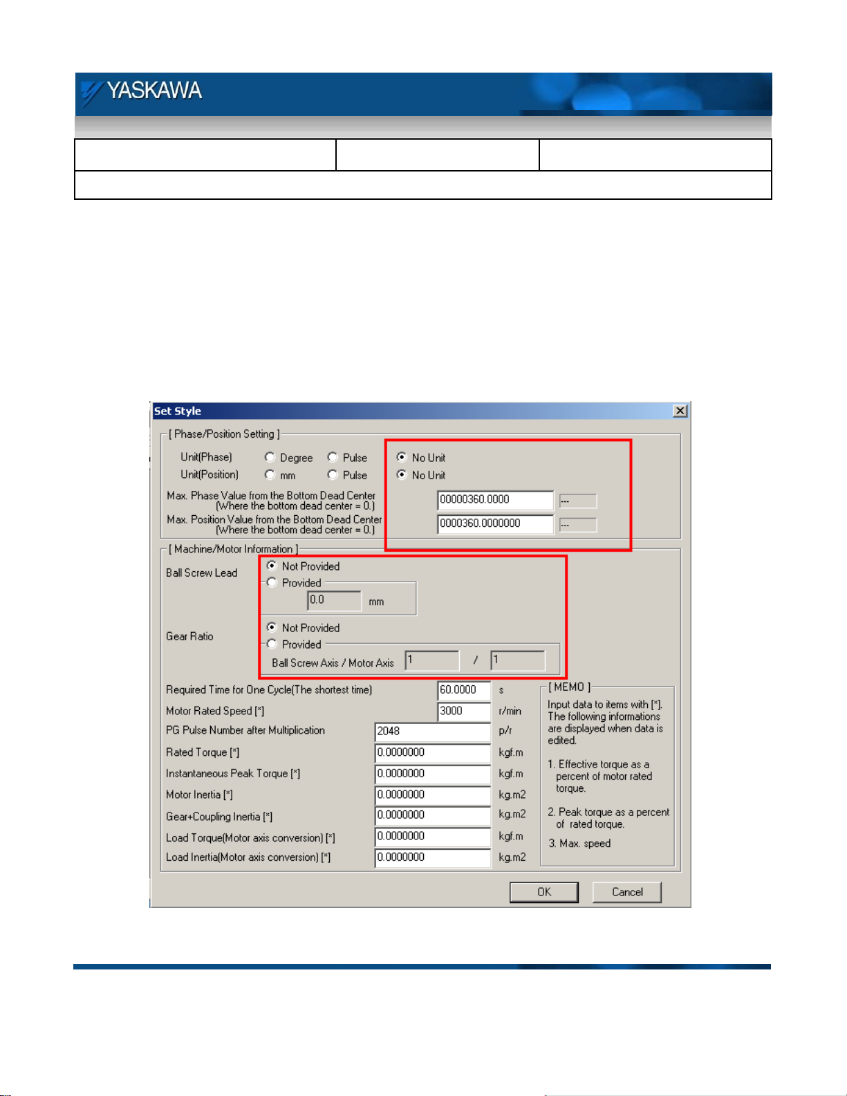
generating cams for use with an MPiec controller. Figure 1 shows Cam Tool’s “Set Style” screen which allows
the user to set the units for generating the cam profile. Master and Slave (a.k.a Phase and Position) units can be
set on this page. Select “No Unit” to indicate that Cam Tool should not perform any position conversion when the
file is saved. Proceed by simply entering all values in user units as defined by MotionWorks IEC’s Configuration
for the appropriate axes. The Machine/Motor Information section is not necessary.
Figure 1: Cam Tool’s Set Style screen for axis configuration
August 30, 2012 Page 3 of 16
Page 4
Subject: Application Note
Product: MPiec
Doc#: EM.MCD.09.043
Title: Implementing Electronic Cams with MPiec: Quick Start Guide
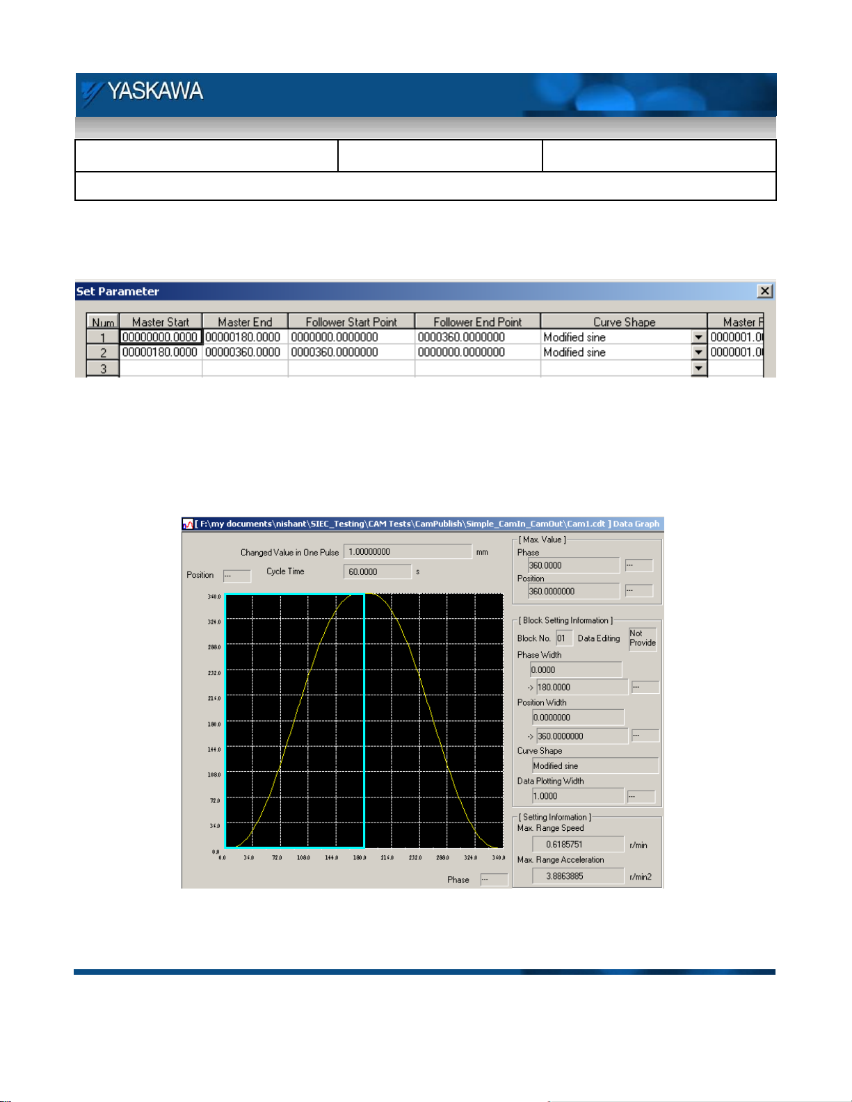
Figure 2 is a screenshot of the “Set Parameter” screen for inputting key points that build the cam profile. A
variety of curves can be selected from the “Curve Shape” drop down menu.
Figure 2: Cam profile generation page
Figure 3 is a screen shot of an “Out and Back” (Two way) cam profile. The X Axis is the master position and the
Y axis is the slave position.
Figure 3: Two way cam profile
August 30, 2012 Page 4 of 16
Page 5
Subject: Application Note
Product: MPiec
Doc#: EM.MCD.09.043
Title: Implementing Electronic Cams with MPiec: Quick Start Guide
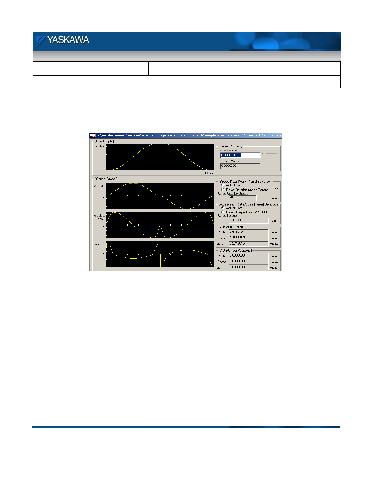
Figure 4 is a screen shot of the control graph that provides analysis the position, velocity, acceleration, and jerk
profiles for the cam profile generated.
Figure 4: Control Graph – Cam analysis screen
Save the cam profile as a cdt or cdd file. Yaskawa recommends one of Cam Tool’s native file types so that
future edits are possible a later time using the Cam Tool application. The MPiec controller accepts csv files for
cam projects. Cam Tool can open a CSV file, however all curve type information will not be restored.
Note: CamTool versions prior to 4.61 do not write a csv file that can be accepted by the MPiec controller.
Yaskawa recommends opening and resaving the file in Microsoft Wordpad or Notepad to store the file as 8 bit
ASCII, not Unicode ASCII.
August 30, 2012 Page 5 of 16
Page 6

Subject: Application Note
Product: MPiec
Doc#: EM.MCD.09.043
Title: Implementing Electronic Cams with MPiec: Quick Start Guide
An example of a one way cam profile been provided in Figure 5.
Figure 5: One way cam profile
August 30, 2012 Page 6 of 16
Page 7

Subject: Application Note
Product: MPiec
Doc#: EM.MCD.09.043
Title: Implementing Electronic Cams with MPiec: Quick Start Guide
4.2 Cam files using Microsoft Excel
The cam CSV file format consists of two columns. The first column is the master position and the second column
contains slave position corresponding to the master. The data can be entered in scientific notation or integer.
After generating the data in Excel, save as a csv file as shown in .
Figure 6: Creating a Cam file using Microsoft Excel
August 30, 2012 Page 7 of 16
Page 8

Subject: Application Note
Product: MPiec
Doc#: EM.MCD.09.043
Title: Implementing Electronic Cams with MPiec: Quick Start Guide
4.3 Cam Application in MotionWorks IEC
Controller Firmware : 1.1.1 build 4
Software IDE : MotionWorks IEC v 1.1.1.7
CamTool version : 4.61
Note:
Before planning to use the camming functions, the user is expected to have basic familiarity with the MPiec
controller and MotionWorks IEC. He/She is expected to understand the basic concepts of electronic camming
and servo based motion controls.
1. Open a new project in MotionWorks IEC Express. Choose an MPiec Project Template.
2. Name and save the project.
3. Go to the Hardware tab. Right click on resource and set the IP address.
4. Make (compile) the project.
5. Open the Configuration.
6. Connect to the controller. (Choose auto-discovered configuration for new project. CNFG switch
should have been on when the controller was powered up.)
August 30, 2012 Page 8 of 16
Page 9

Subject: Application Note
Product: MPiec
Doc#: EM.MCD.09.043
Title: Implementing Electronic Cams with MPiec: Quick Start Guide
7. Click on the MLINK axes individually to configure each axis. Click on the configuration tab to set the
axis type and configure user units.
8. Set the axis type, machine cycle (if axis is rotary), and feed constant (for user units) for the master
axis.
9. Configure user units and machine cycle for the slave axis in the same way. User units and machine
cycle is application dependent. The numbers shown in this example are for a master and slave
system where 360 degrees of the master corresponds to the out and back slave profile shown
below.
August 30, 2012 Page 9 of 16
Page 10

Subject: Application Note
Product: MPiec
Doc#: EM.MCD.09.043
Title: Implementing Electronic Cams with MPiec: Quick Start Guide
10. Save the configuration.
11. Initialize the master and slave axes.
August 30, 2012 Page 10 of 16
Page 11

Subject: Application Note
Product: MPiec
Doc#: EM.MCD.09.043
Title: Implementing Electronic Cams with MPiec: Quick Start Guide
12. Add MC_Power blocks to enable the master and slave axes
13. Add MC_MoveVelocity and MC_Stop blocks for the continuous motion from the master axis.
August 30, 2012 Page 11 of 16
Page 12

Subject: Application Note
Product: MPiec
Doc#: EM.MCD.09.043
Title: Implementing Electronic Cams with MPiec: Quick Start Guide
14. Add a Y_CamFileSelect function block.
The filename is case sensitive and the name of the csv file cannot be more than 8 characters long (8.3
file name format).
The CamTableID set by the Y_CamFileSelect block is input into the Y_CamIn block to engage the cam.
August 30, 2012 Page 12 of 16
Page 13

Subject: Application Note
Product: MPiec
Doc#: EM.MCD.09.043
Title: Implementing Electronic Cams with MPiec: Quick Start Guide
15. Add Y_CamIn block
16. Add a Y_CamOut block
August 30, 2012 Page 13 of 16
Page 14

Subject: Application Note
Product: MPiec
Doc#: EM.MCD.09.043
Title: Implementing Electronic Cams with MPiec: Quick Start Guide
17. Make (compile) the project
18. To add a CSV file to any MP2000iec controller, follow these steps:
Open the Hardware Configuration
Click the “Online” menu
Click the “Controller Configuration Utilities” menu
Select the radio button called “Send Cam Data to Controller”
Select a CSV file.
Press Execute.
The file will be visible from the web server Project Archive list, and it is possible to select the CSV file
using Y_CamFileSelect. Use the directory path in the filename input as shown below:
August 30, 2012 Page 14 of 16
Page 15

Subject: Application Note
Product: MPiec
Doc#: EM.MCD.09.043
Title: Implementing Electronic Cams with MPiec: Quick Start Guide
19. Download the project to the controller
20. Start the PLC and select debug mode.
21. Execute the Y_CamFileSelect block and verify that the Done bit is on and a CamTableID is
generated. If not, the ErrorID output will indicate the type of error. Right click on the function block
when Debug mode is off to access the help file and review the error codes.
22. Enable the axes. Execute Y_CamIn.
23. Execute the master’s MC_MoveVelocity.
24. The slave will follow the master once the master crosses the EngagePosition.
25. To disengage the cam, execute the Camout bit on the Y_CamOut block.
26. To stop the master, execute the MC_Stop block.
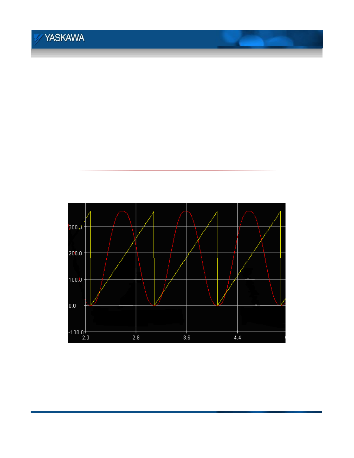
27. The master slave profile will be as described below.
August 30, 2012 Page 15 of 16
Page 16

Subject: Application Note
Product: MPiec
Doc#: EM.MCD.09.043
Title: Implementing Electronic Cams with MPiec: Quick Start Guide
August 30, 2012 Page 16 of 16
 Loading...