

Page 1

TECHNICAL NOTE
MOTION PRODUCT AND ENGINEERING GROUP
Subject: MotionWorks+ Simple Template Program
Product: MP-940, MotionWorks+ v2.83 or later
Engineer: Michael J. Miller
Who should read this document?
Anyone is who is attempting to program an MP-940 Machine Controller, using MotionWorks+
programming environment. This document illustrates a standardized template program to be used
while programming the MP-940 with MotionWorks+. The template includes three main programs:
1) Supervisor
2) Manual
3) Automatic
In addition, eight subroutines are called from two of the main programs. The subroutines include:
1) Jog Forward
2) Jog Reverse
3) Homing
4) Indexing with Programmable Limit Switch (PLS)
5) Gearing
6) Camming
7) Torque
8) Latch with PLS
The program described in this document is meant to be used a starting point for virtually all MP-940
with MotionWorks+ applications. Make use of the subroutines that are appropriate for the application
and discard the subroutines that are not.
Yaskawa Electric America - 2121 Norman Drive South – Waukegan IL 60085
(800) YASKAWA - Fax (847) 887-7280
5/22/2003 1 of 34 eng/PubNumber/MCD
Page 2

TECHNICAL NOTE
MOTION PRODUCT AND ENGINEERING GROUP
Table of Contents
Summary............................................................................................................................4
Programs ............................................................................................................................4
Program Definition ........................................................................................................4
Program Guidelines .......................................................................................................5
1: Supervisor ..................................................................................................................6
Start-up.......................................................................................................................7
Fault Detection...........................................................................................................8
Disable Handler .........................................................................................................8
Fault Recovery...........................................................................................................9
2: Manual .....................................................................................................................10
3: Automatic.................................................................................................................11
Subroutines ......................................................................................................................12
02 Jog +........................................................................................................................12
03 Jog –........................................................................................................................12
04 Home.......................................................................................................................13
05 Move .......................................................................................................................13
Programmable Limit Switch (PLS) .........................................................................14
Timer........................................................................................................................14
06 Gear.........................................................................................................................15
Engaging/Disengaging.............................................................................................15
Running....................................................................................................................16
07 Cam.........................................................................................................................16
Engaging ..................................................................................................................16
Disengaging .............................................................................................................16
08 Torque.....................................................................................................................17
09 Latch .......................................................................................................................17
Latch Target Block ..................................................................................................18
Configuration ...................................................................................................................18
System Parameters.......................................................................................................19
System Properties ........................................................................................................20
SGDH.......................................................................................................................21
MP940......................................................................................................................22
COM1 ......................................................................................................................23
COM2 ......................................................................................................................24
Network....................................................................................................................25
External Encoder......................................................................................................26
Data..................................................................................................................................26
Constants......................................................................................................................27
Network........................................................................................................................28
Tables...........................................................................................................................29
Variables ......................................................................................................................30
I / O ..............................................................................................................................31
Yaskawa Electric America - 2121 Norman Drive South – Waukegan IL 60085
(800) YASKAWA - Fax (847) 887-7280
5/22/2003 2 of 34 eng/PubNumber/MCD
Page 3

TECHNICAL NOTE
MOTION PRODUCT AND ENGINEERING GROUP
Local Input functionality .........................................................................................32
Local Output functionality.......................................................................................33
System Variables .........................................................................................................34
Yaskawa Electric America - 2121 Norman Drive South – Waukegan IL 60085
(800) YASKAWA - Fax (847) 887-7280
5/22/2003 3 of 34 eng/PubNumber/MCD
Page 4
TECHNICAL NOTE
MOTION PRODUCT AND ENGINEERING GROUP
Summary
This document outlines the details of a template example program for an MP-940/SGDH
system. In particular, it was designed with the Yaskawa demonstration (YEA Part # DEMO4700)
unit in mind; however, it can be modified to suit virtually any application, and is commonly used
as a starting point when programming the MP940 using MotionWorks Plus.
There are three main programs: Supervisor, Manual, & Automatic. The Supervisor
program is the only of the three that is auto-starting. Once it starts and some conditions are
satisfied, it starts both Manual & Automatic program. In addition, there are seven subroutines: 02
Jog+, 03 Jog-, 04 Home, 05 Move, 06 Gear, 07 Cam, 08 Torque, and 09 Latch.
While the Manual & Automatic programs may be running, various conditions must be met
for them to start a sub-routine. All of these programs, as well as the configuration for the system
will be discussed. This will be completed in the order that a program in MotionWorks+ is laid out,
according to the Project Explorer window.
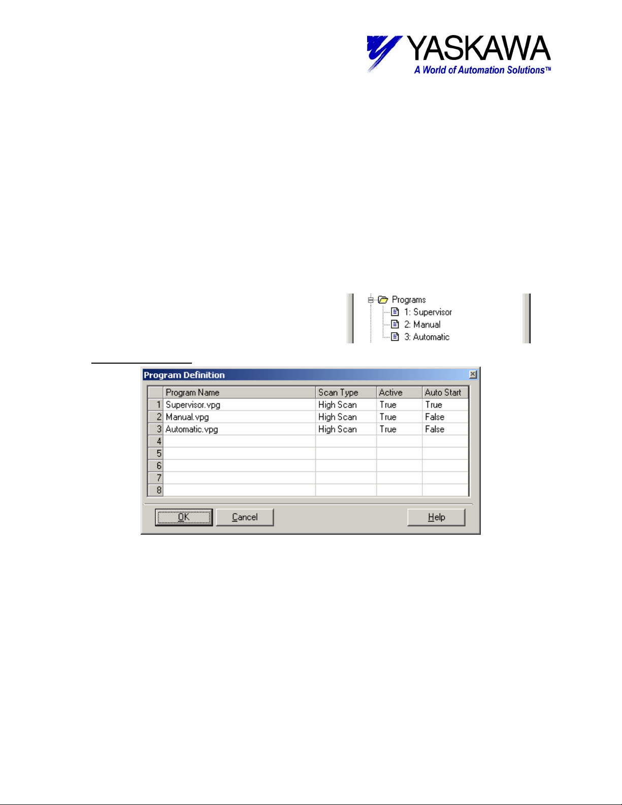
Programs
The Programs folder contains the following:
Supervisor, Manual, and Automatic programs.
Program Definition
Using MotionWorks+ up to eight main programs or tasks are possible. A program can
run in either the High or Low speed Scan. The action or blocks in the program will update at the
selected scan rate.
Auto start is also a possibility for each program. This template program has one program
that is auto starting (Supervisor). Once that program has started and various conditions have
been satisfied, it will start the other programs. If the supervisor detects a fault, error, or other
event it will stop the other programs. This programming methodology creates a solid
infrastructure to build from so that each individual program does not have to monitor for errors,
there is one program the does that and coordinates appropriately.
Yaskawa Electric America - 2121 Norman Drive South – Waukegan IL 60085
(800) YASKAWA - Fax (847) 887-7280
5/22/2003 4 of 34 eng/PubNumber/MCD
Page 5

TECHNICAL NOTE
MOTION PRODUCT AND ENGINEERING GROUP
Lastly, a task can be Active or not. A deactivated program may be some code for feature
that is not available in a particular machine. Keep in mind; deactivated programs still count
towards the maximum of eight total tasks.
Program Guidelines
As a guideline it is recommended that each “program” contain a maximum of 64 total
blocks including all subroutine blocks called from within the program (not including start and stop
blocks). [Version 2.83 of MotionWorks+ includes an update to the compiler that lifts this
restriction, but it is still a good programming practice] In this example, the Supervisor program
utilizes 34 blocks; the Manual program utilizes 35 blocks; the Automatic program utilizes 44
blocks. In addition, it is also recommended that execution of motion effecting blocks, only be
active in one program at a time. For this reason, the Manual and Automatic routines are
interlocked such that they can only operate exclusively.
Blocks that affect motion include the following:
Move Axis
Jog
Stop
Home
CAM
Change Dynamics
Define Position
Gear
Latch Target
Scale CAM
Servo Enable
Torque
Slave Offset
The Supervisor routine utilizes the Servo ON, Stop, and Change Dynamics block, but is closely
monitoring the other programs to ensure that there is no overlapping. Some precautions must
still be followed with the use of Motion Effecting blocks.
Yaskawa Electric America - 2121 Norman Drive South – Waukegan IL 60085
(800) YASKAWA - Fax (847) 887-7280
5/22/2003 5 of 34 eng/PubNumber/MCD
Page 6
TECHNICAL NOTE
MOTION PRODUCT AND ENGINEERING GROUP
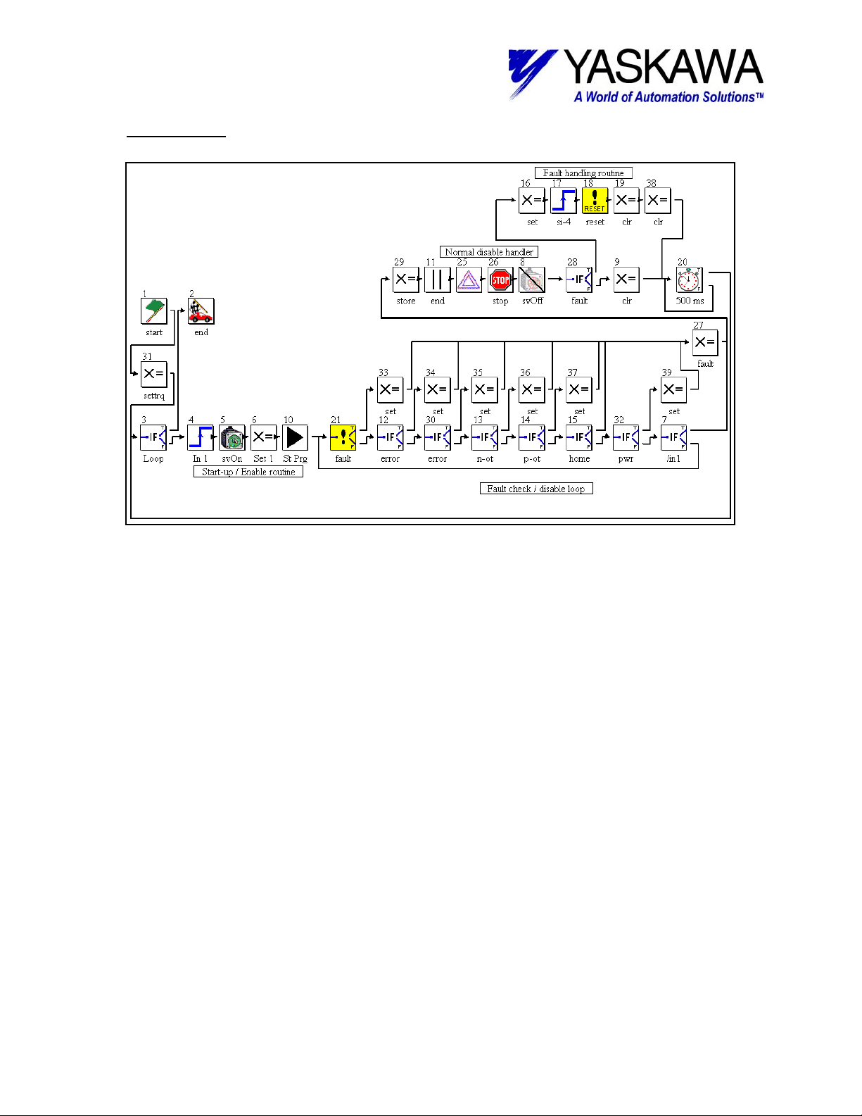
1: Supervisor
The Supervisor is quite daunting at first glance, however, once broken down it is not that
difficult to follow. It can be separated into four distinct sections: Start-up, Fault Detection, Disable
Handler, and Fault Recovery.
Yaskawa Electric America - 2121 Norman Drive South – Waukegan IL 60085
(800) YASKAWA - Fax (847) 887-7280
5/22/2003 6 of 34 eng/PubNumber/MCD
Page 7
TECHNICAL NOTE
MOTION PRODUCT AND ENGINEERING GROUP
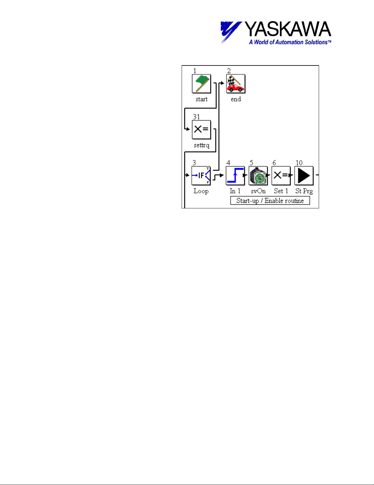
Start-up
The start-up section encompasses
block 3-6, 10, and 31. It is responsible for
startup. Block 31 is executed only once
(upon power up) and can be useful for
setting user variables, or outputs that need
to be reinitialized at power up, but may be
variables themselves. Block 3 has the
condition “False” in and provides a point to
loop back the end of the flow chart, and
ensures that all blocks have connections.
The balance of the blocks regulates a
normal start up.
Block 4 must see the rising edge of
Local_Input1, this assures that input was
activated to enable system, rather than just
left on all of time. Block 5 enables the servo.
Local_Output1 and (user variable)
[SystemOk] is set in Block 6. The [System
Ok] variable is used by the two other main
programs a signal that it is Ok to execute.
The last block (10) starts the other main programs (Manual and Automatic). Lastly
Local_Output4 is set if the system had been previously homed. Only a power cycle will clear the
[Homed] bit indication.
Yaskawa Electric America - 2121 Norman Drive South – Waukegan IL 60085
(800) YASKAWA - Fax (847) 887-7280
5/22/2003 7 of 34 eng/PubNumber/MCD
Page 8
TECHNICAL NOTE
MOTION PRODUCT AND ENGINEERING GROUP
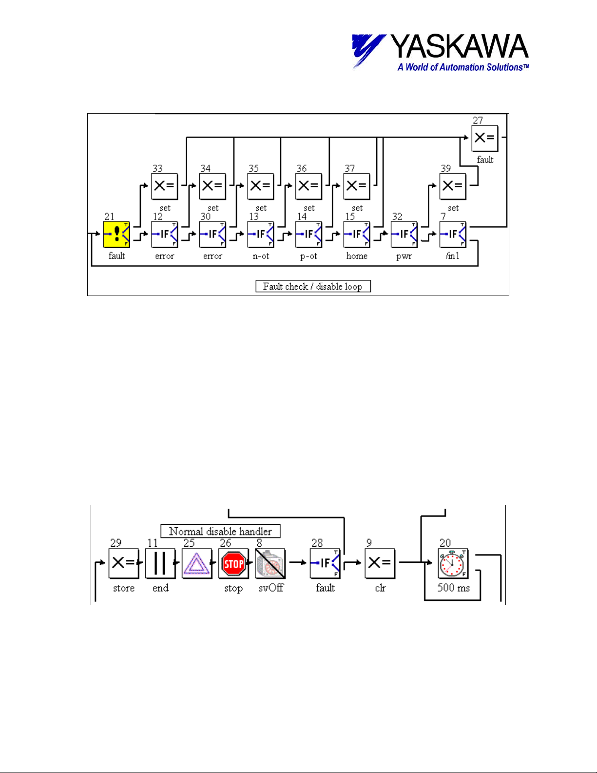
Fault Detection
After the start-up section has been completed successfully, the next section, and the
section that the program will be in most is the Fault Detection / Disable loop. All of the If Event
(including a special If Fault) blocks are designed to detect various faults and errors in the system.
When an error is detected, the next block that is executed is a Set Variable block that sets an
internal flag to trap the type of error that occurred and may also capture some pertinent data.
Lastly, Set Variable block (27) is executed, which sets an internal fault flag and clears the
SystemOk flag, then execution continues to disable handler. If the user simply turns off of the
enable input (Local_Input1), execution continues to disable handler. One thing to keep in mind is
that block 21 does not detect ServoPack warning conditions. ServoPack warning conditions
include any A.9x (where x = 0 – F) alarm code display on SGDH display. The programmer may
want to include additional code to detect these conditions and notify the operator. For example
A.91 is a torque overload warning, indicating that continued operation of the machine at this rate
will result in an A.71 or A.72 torque overload alarm.
Disable Handler
When a fault or a normal disable is detected, this section of code executed. The first
block (29) stores the commanded and actual position (these may be useful in a recovery routine).
Next, the other main programs are halted; the servo is commanded to go to zero speed (25), then
stop (26), and lastly the Servo Off block (8) is executed.
Yaskawa Electric America - 2121 Norman Drive South – Waukegan IL 60085
(800) YASKAWA - Fax (847) 887-7280
5/22/2003 8 of 34 eng/PubNumber/MCD
Page 9
TECHNICAL NOTE
MOTION PRODUCT AND ENGINEERING GROUP
If a fault has occurred block (28) will direct execution to the fault recovery section,
otherwise block (9) is executed. Block (9) clears all of the outputs that may have inadvertently
left on. The Disable handler and the fault recovery routine both make use of Block (20). It is
simply a timer that ensures everything has settled down before attempting a restart. After block
(20) execution continues back to block (3).
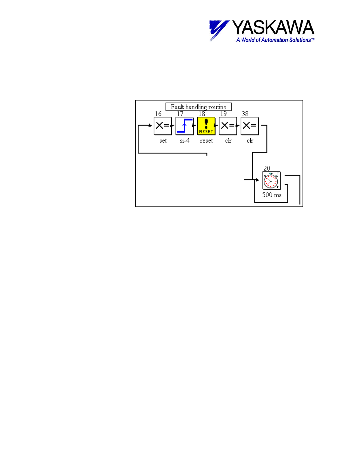
Fault Recovery
Once it has been
determined that a fault
occurred and the appropriate
blocks have executed, the
program ends up in the fault
recovery section. Block (16)
sets an output to indicate that
a fault has occurred (in the
case of the demo box, it
actually sets all eight outputs).
Input block (17) waits to see
the rising edge transition of
SGDH input SI-4
(coincidently, the Servo Alarm
Reset input when the
ServoPack is used alone).
Reset fault block (18) is a
special block that will reset
any ServoPack alarm that does not require a power cycle to reset. Lastly, Set Variable blocks 19
and 38 clear the alarm output and take care of clearing all of the internal error bits. Block (20)
was discussed above in the Disable Handler section. Conveniently, the blocks in the fault
detection section latch the fault type so the operator can tell what type of fault occurred prior to
resetting it. For example if the user variable ‘ErrorCPU’ = 1, then user will know that a MP-940
CPU error occurred. The error code is trapped in another user variable, ‘ErrorCPUCodeTrap.’
Be sure to check these prior to activating the alarm reset, as the bit indications are cleared during
an alarm reset sequence.
Yaskawa Electric America - 2121 Norman Drive South – Waukegan IL 60085
(800) YASKAWA - Fax (847) 887-7280
5/22/2003 9 of 34 eng/PubNumber/MCD
Page 10
TECHNICAL NOTE
MOTION PRODUCT AND ENGINEERING GROUP
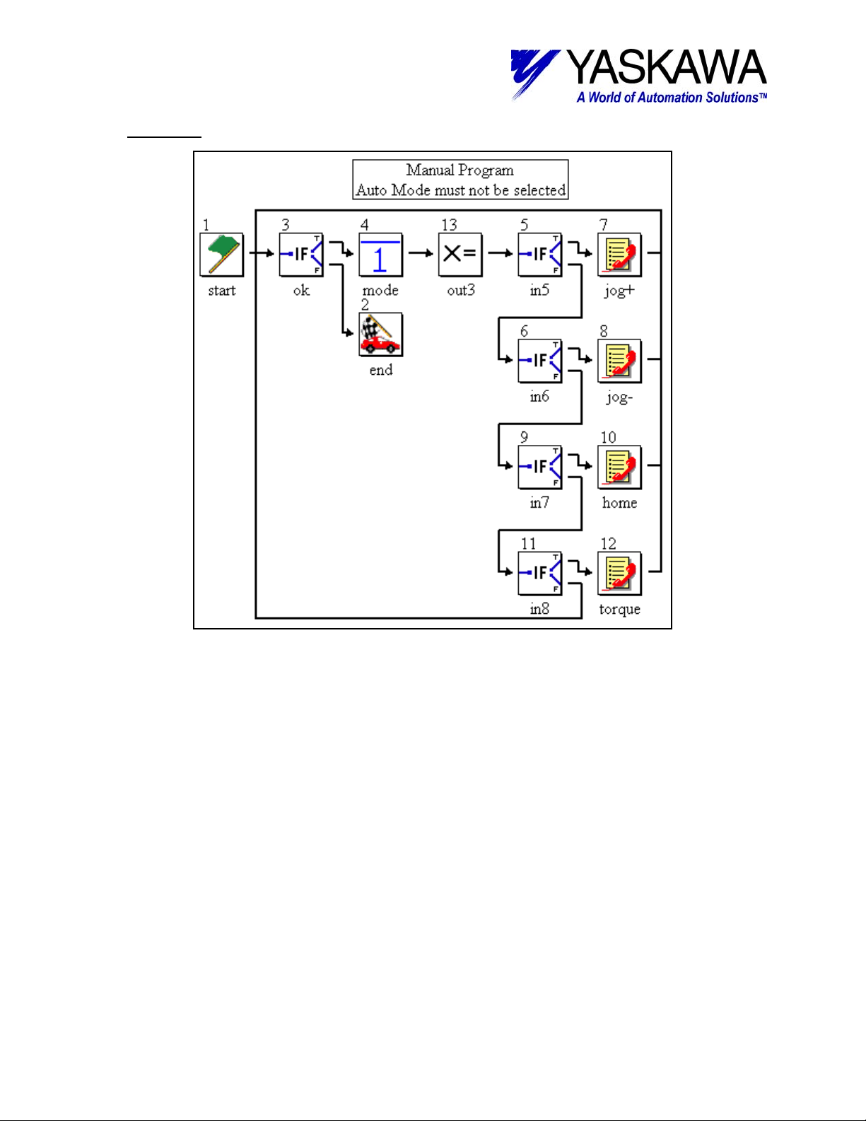
2: Manual
Functions typically performed while in a “manual” mode are included in the manual main
program. While this program is executing it is waiting for the user to activate an input to select a
subroutine program. As long as no input is selected the program scans the blocks in order of 3,
4, 5, 6, 9, and 11 then back to 3.
Two key features in this program are important to mention. First, if event block (3)
detects if (user variable) [SystemOk] is true. As long as this condition is true the program will
stay running (recall SystemOk is controlled by the supervisor program). Second, input block (4)
ensures that (Manual Mode) [!Local_Input2] has been selected. This is a critical interlock that
guarantees that more than one main program is not attempting motion at the same time. This
can be especially unsettling if one program is running the servo in camming mode and another
program is attempting to jog.
Yaskawa Electric America - 2121 Norman Drive South – Waukegan IL 60085
(800) YASKAWA - Fax (847) 887-7280
5/22/2003 10 of 34 eng/PubNumber/MCD
Page 11
TECHNICAL NOTE
MOTION PRODUCT AND ENGINEERING GROUP
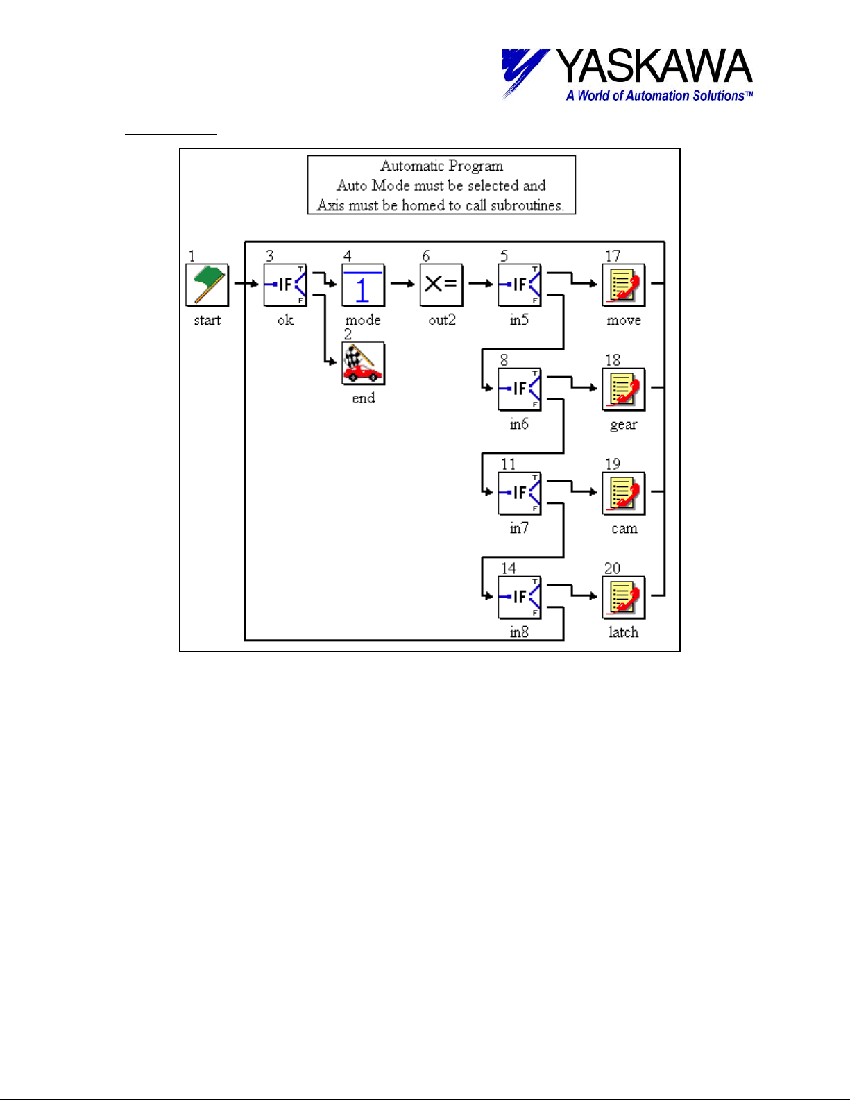
3: Automatic
]
Functions typically performed while in an “automatic” mode are included in the automatic
main program. While this program is executing it is waiting for the user to activate an input to
select a subroutine program. As long as no input is selected, and not in manual mode, the
program scans the blocks in order of 3, 4, 5, 8, 11, 14 then back to 3.
Two key features in this program are important to mention. First, if event block (3)
detects if (user variable) [SystemOk] is true. As long as this condition is true the program will
stay running (recall SystemOk is controlled by the supervisor program). Second, if event block
(4) ensure that (Auto Mode) [Local_Input2] has been selected (in other words if the machine is
not in manual mode, it is in automatic mode) & (homing sequence has been completed) [Homed]
= true. This is a critical interlock that guarantees that more than one main program is not
attempting motion at the same time. This can be especially unsettling if one program is running
the servo in camming mode and another program is attempting to jog.
If a user puts the machine in automatic mode, attempts to execute an automatic
subroutine, nothing will happen, as execution is held at block 4.
Yaskawa Electric America - 2121 Norman Drive South – Waukegan IL 60085
(800) YASKAWA - Fax (847) 887-7280
5/22/2003 11 of 34 eng/PubNumber/MCD
Page 12

TECHNICAL NOTE
MOTION PRODUCT AND ENGINEERING GROUP
Subroutines
The Subroutines folder contains the following:
02 Jog +, 03 Jog -, 04 Home, 05 Move, 06 Gear, 07
Cam, 08 Torque, and 09 Latch subroutines.
A program can have up to 62 subroutines, and
subroutines may be nested up to eight deep.
02 Jog +
The jog + subroutine jogs the servo in the forward direction as long as the user keeps the
jog forward request (Local_Input2) activated. When the user deactivates the jog forward request,
the servo decelerates to a stop and execution is returned to the main program. LocalOutput2 is
activated while servo is in motion jogging. The looping of block 5 to block 4 allows the user to
change the jog velocity while in motion.
03 Jog –
The jog – subroutine jogs the servo in the reverse direction as long as the user keeps the
jog reverse request (Local_Input3) activated. When the user deactivates the jog reverse request,
the servo decelerates to a stop and execution is returned to the main program. LocalOutput3 is
activated while servo is in motion jogging. The looping of block 5 to block 4 allows the user to
change the jog velocity while in motion.
Yaskawa Electric America - 2121 Norman Drive South – Waukegan IL 60085
(800) YASKAWA - Fax (847) 887-7280
5/22/2003 12 of 34 eng/PubNumber/MCD
Page 13

TECHNICAL NOTE
MOTION PRODUCT AND ENGINEERING GROUP
04 Home
The home subroutines takes advantage of the Home block (4) which has built in
functionality for homing to and through a deceleration switch then to the C (zero) pulse of the
encoder. After that is complete an offset move is completed, then the set position block (6) redefines the position to 0.0 (this could be a user variable). In this program that same block also
sets the external position to 0.0 (again that could be a user variable also). The reason for the
time delay block (7) is the position redefinition takes place in the Low Scan (this block actually is
not necessary as the system ladder version 283 has been update to wait until the position has
been updated before moving to the next block). The delay ensures that the block has had
sufficient time to finish before allowing further execution. Blocks 3 and 8 take care of activation
and deactivation of some internal user variables [Homed] and [Homing]. Block sets a user error
variable [ErrorHoming] which is detected in the supervisor. Lastly, input block (10) ensures that
the user has deactivating the homing request input (Local_Input4). If this block was not in place
and the user left the home request on, the machine would home over and over.
05 Move
Move subroutine is simple relative move, which incorporates a programmable limit switch
(PLS) block and a couple of timers. This subroutine differs slightly from the others in that there is
not an event that locks it in the subroutine. Once the move is complete and the timers have
Yaskawa Electric America - 2121 Norman Drive South – Waukegan IL 60085
(800) YASKAWA - Fax (847) 887-7280
5/22/2003 13 of 34 eng/PubNumber/MCD
Page 14
TECHNICAL NOTE
MOTION PRODUCT AND ENGINEERING GROUP
timed out, the subroutine ends and execution is returned to the main calling program. If the input
(input 5) that calls the subroutine is left on the subroutine will be executed again (and again).
The set variable block (3) activates output 5; corresponding block (7) deactivates the
output. Making the output correspond to an “in motion” indicator. The next block, Timer (8)
delays by a user variable [MoveDelay]. Set variable block (9) deactivates any outputs that may
be left on from the PLS. Execution continues to another timer block, with the same user variable
as the earlier timer block.
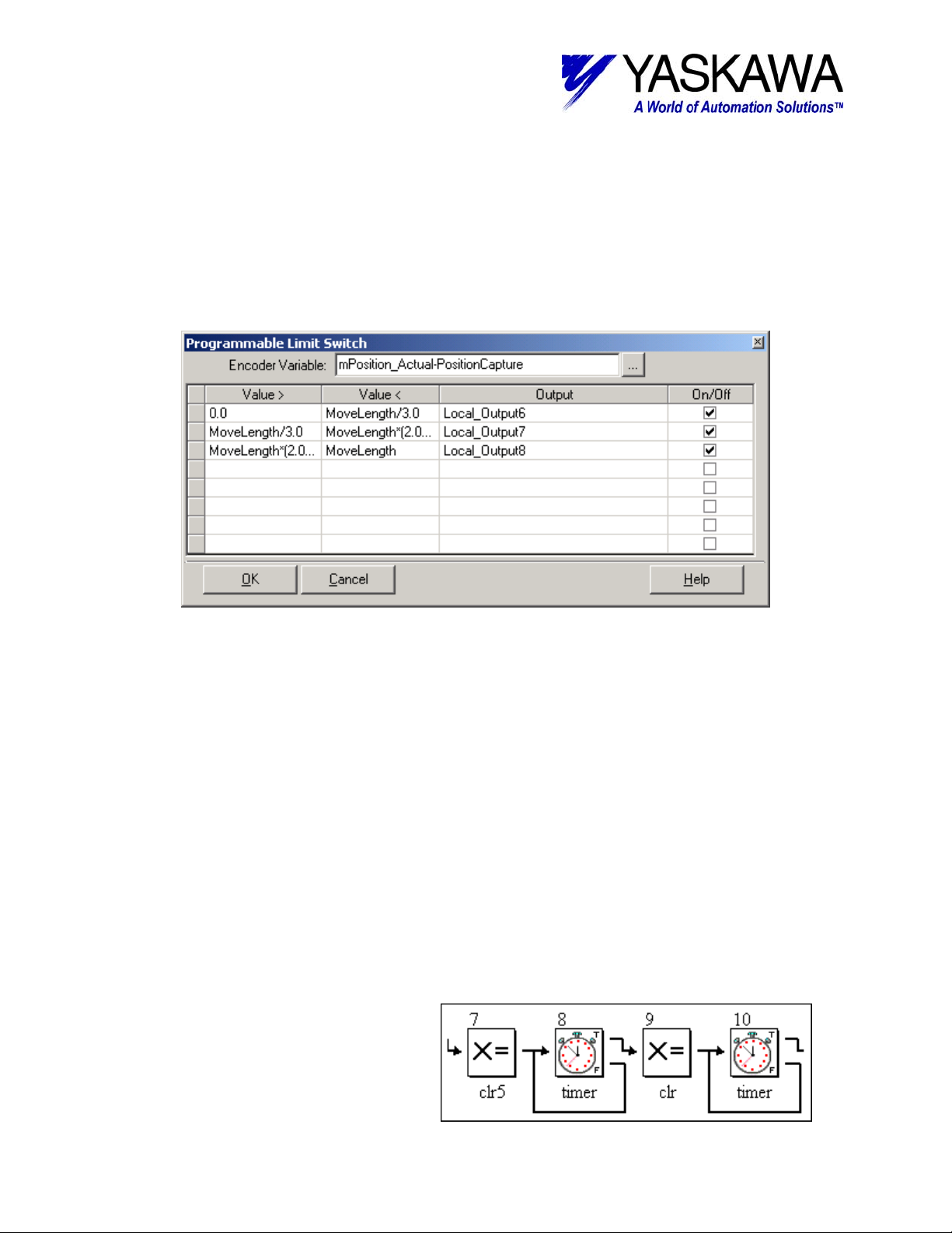
Programmable Limit Switch (PLS)
As the controlled axis is configured in linear mode, the system variable mPosition_Actual
counts up forever (actually until the 32-bit register rolls over, then it counts up again). Therefore,
the current position prior to the move is captured in block 3 in the user variable PositonCapture.
Then mPosition_Actual-PositionCapture is be used as the “Encoder Variable” in the PLS block
(5). With this method the PLS block is modularized automatically per move.
The PLS block implemented in this project is executed in this subroutine and therefore
relies on the Move Block (4) Wait for completion box to be un-checked. It is used in conjunction
with the If Event Block (6) that checks for the move to be complete (system variable
mPosition_Complete), the PLS is updated while in motion.
Entries for (Value >) and (< Value) can be implemented as fixed numbers, user variables,
system variables, and any combination thereof. In addition, the entries can be calculations,
especially useful for applications where PLS outputs also depend on speed of machine. Be
careful with calculation syntax, as ‘C’ syntax is followed. Lastly, when implementing values that
go through (past) zero, it is best to split them up in to two segments [(Value>) to 0] and [0 to
(<Value)] that set internal User bits. Then in a set variable block use those internal user bits
OR
ed together to set the correct output.
Timer
The last few blocks (7-10) are
comprised of set variable and timer
blocks. Some special attention should be
brought up regarding the Timer block.
Yaskawa Electric America - 2121 Norman Drive South – Waukegan IL 60085
(800) YASKAWA - Fax (847) 887-7280
5/22/2003 14 of 34 eng/PubNumber/MCD
Page 15

TECHNICAL NOTE
MOTION PRODUCT AND ENGINEERING GROUP
The timer block, while it has two out ports, the false port should always be looped back to the in
port of the block. Time only accumulates while the block is being executed, thus the need for the
loop back. If items are connected between the false port and the in port, it can cause the timer to
take additional time to complete. For example, if a block is inserted between the false port and
the return to the true port, and it takes one scan to execute that block, the amount of time will be
doubled. One last thing to remember about the Timer block is that the time value in it is retentive.
In other words, if the timer starts timing and for some reason gets interrupted, (program is halted,
etc) upon re-entering said timer block it will finish timing.
There is an alternative way to construct a timer. A system variable exists, mTime, this
variable increments every high scan. A user can capture the value of mTime in a set variable
block. In the next block, an If Event block, compare if mTime > CaptureTime + DesiredTime.
While that condition is false the program can monitor other events and return to the in port of the
If Event block. Be careful with this method, as the timed value can vary if there is a lot of logic
between the false port and the return to the in port.
06 Gear
The Gear subroutine is fairly straightforward, for discussion purposes it is broken down
into two sections. The two sections include: Engaging/Disengaging, and Running.
Engaging/Disengaging
Blocks 3 –
4 & 7 – 9 comprise
engaging and
disengaging of
gearing. Blocks 3
and 9 take care of
activating /
deactivating
Output 6 while entering / leaving gearing subroutine. The key element to remember is after the
disengage block include a stop block. If the stop block is not included and the slave is
disengaged while the master is motion, the slave will continue to gear to the last known
calculated speed of the master axis. Additionally, the stop block will switch the axis to position
mode, allowing a controlled deceleration to zero speed and will maintain position once stopped.
Yaskawa Electric America - 2121 Norman Drive South – Waukegan IL 60085
(800) YASKAWA - Fax (847) 887-7280
5/22/2003 15 of 34 eng/PubNumber/MCD
Page 16

TECHNICAL NOTE
MOTION PRODUCT AND ENGINEERING GROUP
Running
The rest of the blocks are executed while the system is
engaged in gearing (or running). The user is able to adjust the
gearing ratio by modifying the variables (user variables [GearMaster]
divided by [GearSlave]) in the Gear Ratio block (5). The gear ratio is a
fraction of two integer numbers, be careful not to use floating-point
variables for these. The values will be truncated and lost motion may
be realized.
07 Cam
The Cam subroutine looks quite difficult at first glance, however it is actually quite simple.
Broken down into three sections, makes it easier to follow. The three sections include: Engaging,
Disengaging, and Running. (Note: Cam table generation, using Cam Tool is beyond the scope of
this document)
Engaging
The Cam engage consists of block 3-5. The Cam
engages at a particular Master position based on the value
entered in block three, for this program 0 master units is the
position used. Block 3 also sets the system variable
mState_Camming = 1, this indicates that the system is
waiting to engage. While waiting to engage
(mState_Camming = 1) execution is held at block 4. Once
engaged (mState_Camming = 2) output 7 is turned on solid.
Disengaging
Disengagement begins after input 7 has been
deactivated and consists of block 8-10. This works quite
similarly to engaging, in Block 8 the disengage position is
specified. Again, for this program 0 master units is the
position used. Block 8 sets mState_Camming = 4, while
disengaging execution is held at block 9. Once the
disengage position has passed (mState_Camming = 0),
output 7 is deactivated and the subroutine is exited.
Yaskawa Electric America - 2121 Norman Drive South – Waukegan IL 60085
(800) YASKAWA - Fax (847) 887-7280
5/22/2003 16 of 34 eng/PubNumber/MCD
Page 17

TECHNICAL NOTE
MOTION PRODUCT AND ENGINEERING GROUP
Running
The rest of the blocks are executed while the system is
engaged in camming (or running). The user is able to scale the cam by
modifying the variable (user variable [CamScale]) in the Cam Scale
block (14). The scale factor is a percentage of the original cam, where
100.00% represents the original cam size. A value larger than 100%
equates to an expanded cam, less equals a contract cam.
08 Torque
The torque subroutine is quite simple. Once entered from the calling program the motor
applies a variable amount of torque (based on a user variable [TorqueToApply]) and activates
output 8. It also limits the velocity of the motor (based on a user variable [Vel]). As long as input
8 is activated this is continued. Once input 8 is deactivated the servo is decelerated to stop,
output 8 is deactivated and the subroutine is exited.
09 Latch
The latch subroutine works very similarly to the move subroutine. The main difference is
the move block has been replaced with a Latch Target block (4). Additionally, the values in PLS
Yaskawa Electric America - 2121 Norman Drive South – Waukegan IL 60085
(800) YASKAWA - Fax (847) 887-7280
5/22/2003 17 of 34 eng/PubNumber/MCD
Page 18

TECHNICAL NOTE
MOTION PRODUCT AND ENGINEERING GROUP
block (5) has modified to be more suitable for the Latch routine. It has been configured to
activate output during the various states of latching as described in the graphic above. Lastly,
the logic in blocks (9 & 10) cause Output 7 to activate if a latch is detected during the move. This
can very helpful when troubleshooting using the Scope functionality of MotionWorks+.
Latch Target Block
The latch target block is a
pre-configured block that allows the
user to make use of the high speed
(captures position in 30
microseconds or less) without
knowing the ins and outs
arming/disarming/windowing the
latch signal. The block is much like
a move block; in fact if a latch is not
received it will work identically to a
move axis block (Default Distance in
Latch Target block = Position in
move block). However, if a Latch
signal is received then the servo will
move the Distance After Latch from
the point where the latch was
detected.
Occasionally false latches
can be a problem and cause the
servo to move an incorrect distance.
The Latch Start and Finish Distance
parameters are useful in removing unwanted latch signals. They are used to set-up a window in
which the latch is expected.
Configuration
The Configuration folder contains: System
Parameters and System Properties configuration.
Yaskawa Electric America - 2121 Norman Drive South – Waukegan IL 60085
(800) YASKAWA - Fax (847) 887-7280
5/22/2003 18 of 34 eng/PubNumber/MCD
Page 19
TECHNICAL NOTE
MOTION PRODUCT AND ENGINEERING GROUP
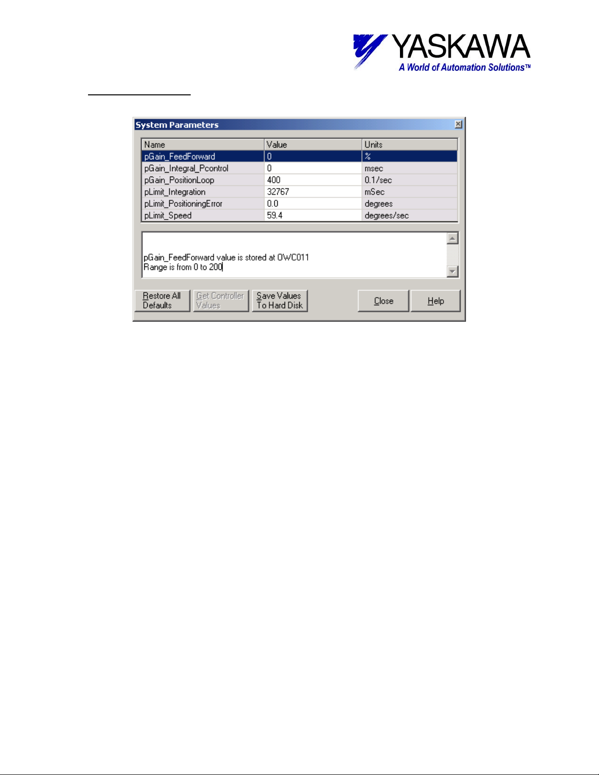
System Parameters
System Parameters have all been left at factory default. The user may need to modify
some of these parameters when tuning the system. One thing to keep in mind is that leaving
“pLimit_PositioningError” = 0.0 sets the controller to ignore following error.
Yaskawa Electric America - 2121 Norman Drive South – Waukegan IL 60085
(800) YASKAWA - Fax (847) 887-7280
5/22/2003 19 of 34 eng/PubNumber/MCD
Page 20

TECHNICAL NOTE
MOTION PRODUCT AND ENGINEERING GROUP
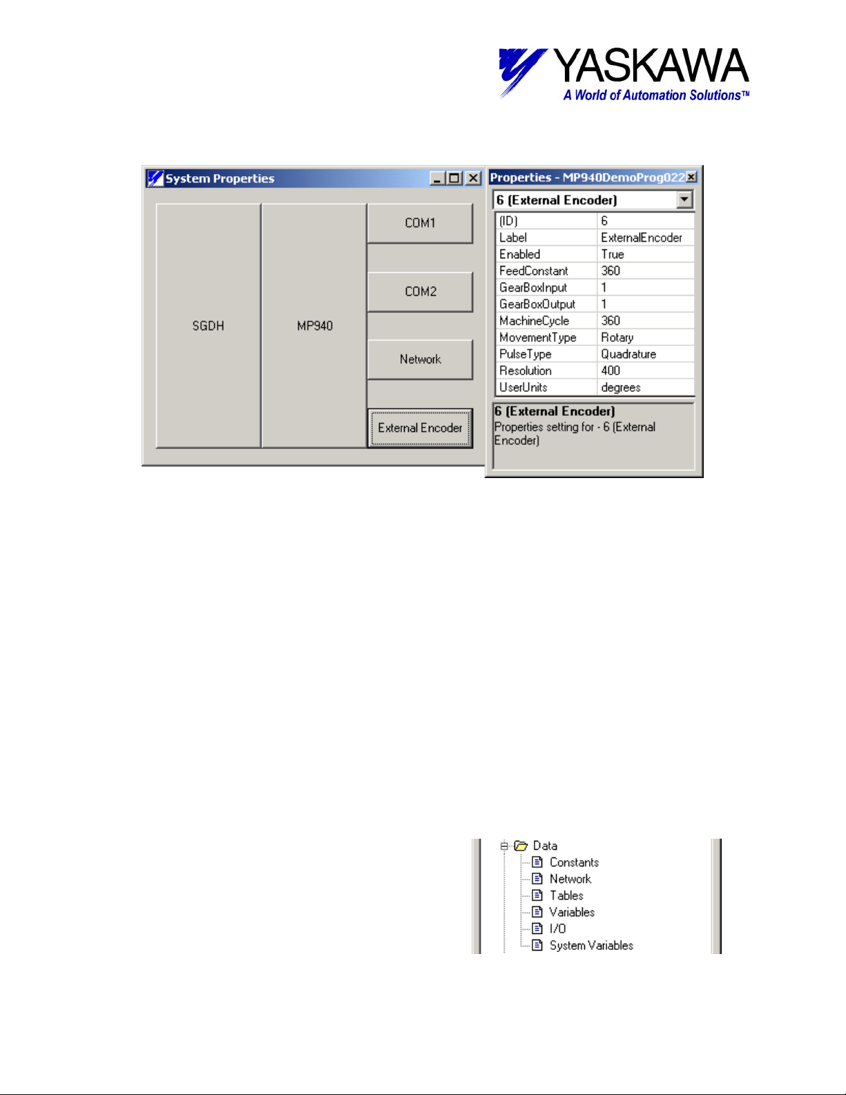
System Properties
The System Properties consist of: SGDH, MP-940, COM1, COM2, Network, and External
Encoder configuration.
Yaskawa Electric America - 2121 Norman Drive South – Waukegan IL 60085
(800) YASKAWA - Fax (847) 887-7280
5/22/2003 20 of 34 eng/PubNumber/MCD
Page 21

TECHNICAL NOTE
MOTION PRODUCT AND ENGINEERING GROUP
SGDH
All SGDH parameters are left at factory default for this example. The user may need to
modify some user parameters when tuning the system.
Yaskawa Electric America - 2121 Norman Drive South – Waukegan IL 60085
(800) YASKAWA - Fax (847) 887-7280
5/22/2003 21 of 34 eng/PubNumber/MCD
Page 22

TECHNICAL NOTE
MOTION PRODUCT AND ENGINEERING GROUP
MP940
Only five parameters were modified in the MP-940 properties to correspond with the
demo unit, they are as follows:
• BatteryTest Enabled
• FeedConstant: 10 mm
• Firmware: (Uploaded from Controller)
• HighScanSetting: 2 milliseconds
• LoadType: Linear
• MachineCycle: 1 mm
• UserUnits: mm
These were modified to convert the SGMAH-01BAF41 of the demo to a linear mode. So
that 8192 pulses, which is one revolution, equates to 10 mm and counts up. The Scan time was
increased due to the large program size. This will eliminate nuisance over scan errors (A.E2 on
Yaskawa Electric America - 2121 Norman Drive South – Waukegan IL 60085
(800) YASKAWA - Fax (847) 887-7280
5/22/2003 22 of 34 eng/PubNumber/MCD
Page 23

TECHNICAL NOTE
MOTION PRODUCT AND ENGINEERING GROUP
SGDH Display). The battery test can be left at disabled if system does not include a battery
backup. However, user should be concerned about data and program maintainability during
extended power off time. The use of Flash memory is out of the scope of this document.
COM1
Com1 parameters were left at factory default. Leaving them in this configuration allows
for correct connection to MotionWorks+ software.
Yaskawa Electric America - 2121 Norman Drive South – Waukegan IL 60085
(800) YASKAWA - Fax (847) 887-7280
5/22/2003 23 of 34 eng/PubNumber/MCD
Page 24

TECHNICAL NOTE
MOTION PRODUCT AND ENGINEERING GROUP
COM2
Com2 parameters were left at factory default. Leaving them in this configuration allows
for easy connection to Yaskawa HMI. Connection to an HMI is beyond the scope of this
document.
Yaskawa Electric America - 2121 Norman Drive South – Waukegan IL 60085
(800) YASKAWA - Fax (847) 887-7280
5/22/2003 24 of 34 eng/PubNumber/MCD
Page 25

TECHNICAL NOTE
MOTION PRODUCT AND ENGINEERING GROUP
Network
The Network system properties were not modified from defaults, as no field bus
(Mechatrolink or DeviceNet) was implemented in this project.
Yaskawa Electric America - 2121 Norman Drive South – Waukegan IL 60085
(800) YASKAWA - Fax (847) 887-7280
5/22/2003 25 of 34 eng/PubNumber/MCD
Page 26
TECHNICAL NOTE
MOTION PRODUCT AND ENGINEERING GROUP
External Encoder
Only five parameters were modified in the External Encoder properties to correspond
with the demo unit, they are as follows:
• Enabled: True
• FeedConstant: 360 degrees
• MachineCycle: 360 degrees
• Resolution: 400 post quadrature counts
• UserUnits: degrees
These were modified to convert the Pulse Generator of the demo to a rotary mode. So
that 400 pulses, which is one revolution, equates to 360 degrees and that it rolls over
automatically at 360 degrees.
Data
The Data folder contains: Constants, Network, Tables,
Variables, I/O, and System Variables configuration.
Yaskawa Electric America - 2121 Norman Drive South – Waukegan IL 60085
(800) YASKAWA - Fax (847) 887-7280
5/22/2003 26 of 34 eng/PubNumber/MCD
Page 27

TECHNICAL NOTE
MOTION PRODUCT AND ENGINEERING GROUP
Constants
No User constants were defined for this project. This is where the user can define
constants to be used in the program.
Yaskawa Electric America - 2121 Norman Drive South – Waukegan IL 60085
(800) YASKAWA - Fax (847) 887-7280
5/22/2003 27 of 34 eng/PubNumber/MCD
Page 28

TECHNICAL NOTE
MOTION PRODUCT AND ENGINEERING GROUP
Network
This demo program is written without the field-bus configured. This is where the user
can implement network variables (Mechatrolink or DeviceNet, hardware dependent).
Yaskawa Electric America - 2121 Norman Drive South – Waukegan IL 60085
(800) YASKAWA - Fax (847) 887-7280
5/22/2003 28 of 34 eng/PubNumber/MCD
Page 29

TECHNICAL NOTE
MOTION PRODUCT AND ENGINEERING GROUP
Tables
One CAM table has been created with Yaskawa CamTool. Use of CamTool is out of the
scope of this document. Additional CAM tables, CSV files, and empty arrays can be created in
the table definition.
Yaskawa Electric America - 2121 Norman Drive South – Waukegan IL 60085
(800) YASKAWA - Fax (847) 887-7280
5/22/2003 29 of 34 eng/PubNumber/MCD
Page 30
TECHNICAL NOTE
MOTION PRODUCT AND ENGINEERING GROUP
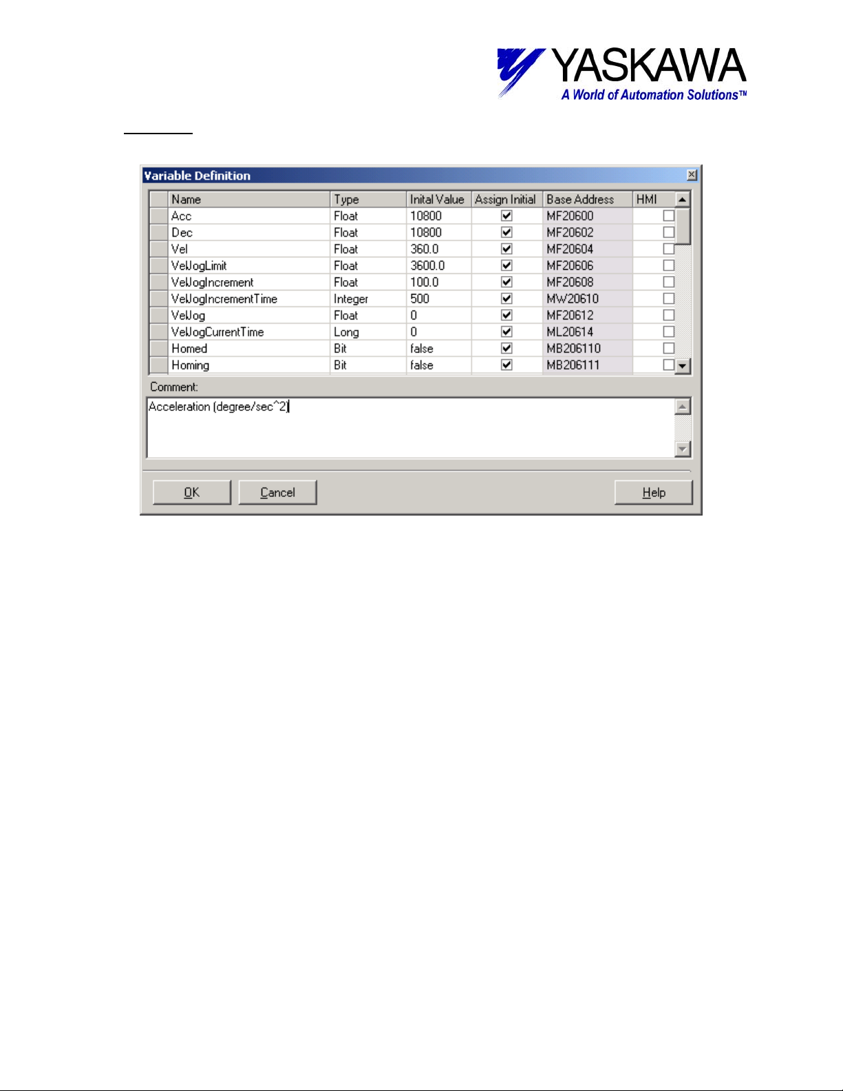
Variables
Several user variables have been created for this program. User can add or modify to
suit application needs.
Yaskawa Electric America - 2121 Norman Drive South – Waukegan IL 60085
(800) YASKAWA - Fax (847) 887-7280
5/22/2003 30 of 34 eng/PubNumber/MCD
Page 31

TECHNICAL NOTE
MOTION PRODUCT AND ENGINEERING GROUP
I / O
For ease of use, I/O settings were left at factory default naming conventions. The names
could be modified to suit a particular application
Yaskawa Electric America - 2121 Norman Drive South – Waukegan IL 60085
(800) YASKAWA - Fax (847) 887-7280
5/22/2003 31 of 34 eng/PubNumber/MCD
Page 32

TECHNICAL NOTE
MOTION PRODUCT AND ENGINEERING GROUP
Local Input functionality
Input Functionality Description
MW+ Name (SGDH Ref) Manual Automatic
Local_Input1 Servo Enable Enables Servo and Starts manual/auto programs
Local_Input2 Off* On* *Off Selects Manual, On Selects Automatic
Local_Input3 - - Not Used
Local_Input4 - - Not Used
Local_Input5 Jog Forward Index Mode Dependent
Local_Input6 Jog Reverse Gear Mode Dependent
Local_Input7 Home Cam Mode Dependent
Local_Input8 Torque Latch Mode Dependent
Sigma_ServoOn (SI-0) - - Not Used
Sigma_HomeInput (SI-1) Home SW - Home Switch Input
Sigma_POT (SI-2) P-OT Positive Over Travel
Sigma_NOT (SI-3) N-OT Negative Over Travel
Sigma_EXT1 (SI-4) Alarm Reset* *Only applicable after alarm has occurred
Sigma_EXT2 (SI-5) - - Not Used
Sigma_Latch_Input (SI-6) - Latch Input* *Only applicable while in Latch routine
Yaskawa Electric America - 2121 Norman Drive South – Waukegan IL 60085
(800) YASKAWA - Fax (847) 887-7280
5/22/2003 32 of 34 eng/PubNumber/MCD
Page 33

TECHNICAL NOTE
MOTION PRODUCT AND ENGINEERING GROUP
Local Output functionality
Output Functionality Description
MW+ Name All Modes
Local_Output1 Servo Enabled On when Servo Enabled
Local_Output2 Manual Mode On when in Manual Mode
Local_Output3 Automatic Mode On when in Automatic Mode
Local_Output4 Homed On when system has been homed
Local_Output5 Jogging Fwd On when jogging forward
Local_Output6 Jogging Rev On when jogging reverse
Local_Output7 Homing On while homing
Local_Output8 Applying Torque On while applying torque
Local_Output5 Index On while indexing
Local_Output6 Gear On while Gearing
Local_Output7 Cam On while Camming
All Modes
Manual Mode
Automatic
Mode
Local_Output8 Latch On during latch routine
Local_Output6 PLS On first third of move
Local_Output7 PLS On second third of move
Local_Output8 PLS On last third of move
Local_Output5 PLS On when Latch Window Starts
Local_Output6 PLS On during Latch Window
Local_Output7 Latch On if Latch Signal detected (between start & end of window)
Yaskawa Electric America - 2121 Norman Drive South – Waukegan IL 60085
5/22/2003 33 of 34 eng/PubNumber/MCD
While Indexing
While Latching
(800) YASKAWA - Fax (847) 887-7280
Page 34

TECHNICAL NOTE
MOTION PRODUCT AND ENGINEERING GROUP
System Variables
Only four parameters were modified in the System Variables to correspond with the
demo unit, they are as follows:
• sLimit_Speed_Negative: 833.33 mm/sec
• sLimit_Speed_Positive: 833.33 mm/sec
• sLimit_Torque: -30000 (.01% rated torque)
• sPosition_CompletionWindow: 1.0 mm
These were modified to allow full peak motor rpm (5000), and allow full motor peak
torque be developed. Lastly, in the completion window allows for an incompletely tuned system
to be operated with consistency.
Yaskawa Electric America - 2121 Norman Drive South – Waukegan IL 60085
(800) YASKAWA - Fax (847) 887-7280
5/22/2003 34 of 34 eng/PubNumber/MCD
 Loading...