

Page 1
YASKAWA
Machine Controller MP930
USER'S MANUAL
DESIGN AND MAINTENANCE
YA S K A WA
MANUAL NO. SIEZ-C887-1.1
Page 2
Safety Information
The following conventions are used to indicate precautions in this manual. Failure to heed precau-
tions provided in this manual can result in serious or possibly even fatal injury or damage to the prod-
ucts or to related equipment and systems.
Safety Information
WARNING
!
Caution Indicates precautions that, if not heeded, could result in relatively serious or minor
!
The warning symbols for ISO and JIS standards are different, as shown below.
The ISO symbol is used in this manual.
Both of these symbols appear on warning labels on Yaskawa products. Please abide by
these warning labels regardless of which symbol is used.
Indicates precautions that, if not heeded, could possibly result in loss of life or
serious injury.
injury, damage to the product, or faulty operation.
ISO JIS
Yaskawa, 1999
All rights reserved. No part of this publication may be reproduced, stored in a retrieval system, or transmitted, in any form,
or by any means, mechanical, electronic, photocopying, recording, or otherwise, without the prior written permission of
Yaskawa. No patent liability is assumed with respect to the use of the information contained herein. Moreover, because
Yaskawa is constantly striving to improve its high-quality products, the information contained in this manual is subject to
change without notice. Every precaution has been taken in the preparation of this manual. Nevertheless, Yaskawa assumes no responsibility for errors or omissions. Neither is any liability assumed for damages resulting from the use of the
information contained in this publication.
iii
Page 3
Visual Aids
The following aids are used to indicate certain types of information for easier reference.
A
EXAMPLE
INFO
IMPORTANT
TERMS
Indicates application examples.
"
Indicates supplemental information.
Indicates important information that should be memorized.
Describes technical terms that are difficult to understand, or appear in the text without an
explanation being given.
iv
Page 4

TABLE OF CONTENTS
TABLE OF CONTENTS
Safety Information iii...............................................
Visual Aids iv.....................................................
Overview ix.......................................................
Using This Manual x...............................................
Safety Precautions xi..............................................
1 MP930
1.1 Overview of the MP930 1 - 2.....................................
1.1.1 Appearance of MP930 Units 1 - 2...........................................
1.1.2 Features of the MP930 1 - 3................................................
1.2 Control Using the MP930 1 - 5....................................
1.2.1 Types of Program 1 - 5.....................................................
1.2.2 Ladder Logic Programs 1 - 6................................................
1.2.3 MC Programs 1 - 8........................................................
1.2.4 Control Signals 1 - 9.......................................................
1.3 Operation from Programming Devices 1 - 10.......................
1.3.1 File Manager 1 - 10.........................................................
1.3.2 System Information Definitions 1 - 11.........................................
1.3.3 Programming 1 - 12........................................................
1.3.4 Debugging and Monitoring 1 - 13.............................................
1.3.5 Printing 1-13.............................................................
2 MP930 Specifications and System Configuration
2.1 Specifications 2 - 2..............................................
2.1.1 General Specifications 2 - 2................................................
2.1.2 Hardware Specifications 2 - 3...............................................
2.1.3 Function List 2 - 4.........................................................
2.2 Basic System Configuration 2 - 31.................................
2.2.1 List of Basic Units 2 - 31....................................................
2.2.2 Basic System Configuration 2 - 32............................................
2.2.3 Precautions on System Configuration 2 - 33...................................
2.2.4 Programming Device 2 - 34..................................................
3 Basic System Operation
3.1 Operating Modes 3 - 2...........................................
3.1.1 Online Operating Mode 3 - 2................................................
3.1.2 Offline Stop Mode 3 - 2....................................................
3.2 Start and Stop Sequences 3 - 3..................................
3.2.1 DIP Switch Settings 3 - 3...................................................
3.2.2 Start Sequence 3 - 5......................................................
v
Page 5

3.3 Power Failures 3 - 8.............................................
3.3.1 Power Failure Detection 3 - 8...............................................
3.4 User Programs 3 - 9.............................................
3.4.1 Drawings (DWGs) 3 - 9....................................................
3.4.2 Execution Control of Parent Drawings 3 - 10...................................
3.4.3 Motion Programming 3 - 14..................................................
3.5 Functions 3 - 22..................................................
3.5.1 Standard System Functions 3 - 22............................................
3.5.2 Creating User Functions 3 - 23...............................................
3.6 Registers 3 - 28..................................................
3.6.1 Register Designation Methods 3 - 28..........................................
3.6.2 Data Types 3 - 29..........................................................
3.6.3 Types of Register 3 - 33.....................................................
3.6.4 Using Subscripts I and J 3 - 36...............................................
3.6.5 I/O and Registers in Functions 3 - 38.........................................
3.6.6 Register Ranges in Programs 3 - 39..........................................
3.7 Managing Symbols 3 - 40.........................................
3.7.1 Symbols in Drawings 3 - 40..................................................
3.7.2 Symbols in Functions 3 - 41.................................................
3.7.3 Upward Linking of Symbols 3 - 42............................................
3.7.4 Automatic Register Number Allocation 3 - 43...................................
4 System Startup
4.1 Part Names 4 - 2................................................
4.1.1 MC Unit 4-2.............................................................
4.1.2 I/O Unit 4-6.............................................................
4.2 Connection Methods 4 - 8.......................................
4.2.1 Names and Locations of Connectors 4 - 8....................................
4.2.2 System Connection Example 4 - 9...........................................
4.2.3 Standard Cables 4 - 10.....................................................
4.2.4 Connector Pin Layout and I/O Circuits 4 - 12...................................
4.2.5 Connections to the Servopack and Motor 4 - 21................................
4.3 System Startup Methods 4 - 24....................................
4.3.1 Overview of the Startup Procedure 4 - 24......................................
4.3.2 Test Unit Configuration 4 - 25................................................
4.3.3 Equipment Preparations 4 - 26...............................................
4.3.4 Mounting the Units 4 - 27....................................................
4.3.5 Connecting the Devices 4 - 30...............................................
4.3.6 Starting the CP-717 4 - 39...................................................
4.3.7 Motion Parameter Settings 4 - 53.............................................
4.3.8 Creating and Saving Motion Programs 4 - 56..................................
4.3.9 Ladder Logic Programs 4 - 60................................................
4.3.10 Transferring Definitions, Parameters, and Programs 4 - 75......................
4.3.11 Checking Operations 4 - 81.................................................
vi
Page 6

TABLE OF CONTENTS
5 Parameters
5.1 Description of Parameters 5 - 2..................................
5.1.1 Parameter Classifications 5 - 2..............................................
5.1.2 Parameter Lists 5 - 3......................................................
5.2 Parameter Settings 5 - 17.........................................
5.2.1 Fixed Parameters 5 - 17....................................................
5.2.2 Setting Parameters 5 - 21...................................................
5.2.3 Monitor Parameters 5 - 30...................................................
6 Controlled Axis Support Functions
6.1 Support Functions for Controlled Axes 6 - 2......................
6.1.1 Reference Unit 6 - 2.......................................................
6.1.2 Electronic Gear 6 - 3......................................................
6.1.3 Override Function 6 - 5....................................................
6.1.4 Infinite Length Positioning 6 - 6.............................................
6.1.5 Stroke Limit Function 6 - 8.................................................
7 Absolute Position Detection
7.1 Structure of the Absolute Position Detection Function 7 - 2........
7.1.1 Description of the Function 7 - 2............................................
7.1.2 Structure of Absolute Position Detection 7 - 2.................................
7.2 Starting the Absolute Position Detection Function 7 - 5............
7.2.1 System Startup Procedure 7 - 5.............................................
7.2.2 Setting Related Parameters 7 - 6............................................
7.2.3 Initializing the Absolute Encoder 7 - 8........................................
7.3 Using an Absolute Encoder 7 - 10.................................
7.3.1 Finite Length Mode Axis 7 - 10...............................................
7.3.2 Infinite Length Mode Axis 7 - 14..............................................
8 Maintenance and Inspection
8.1 Inspection Items 8 - 2...........................................
8.1.1 Daily Inspections 8 - 2.....................................................
8.1.2 Regular Inspections 8 - 3...................................................
8.2 Battery 8 - 5....................................................
8.2.1 Battery Life 8 - 5..........................................................
8.2.2 Battery Replacement 8 - 5..................................................
vii
Page 7

9 Troubleshooting
Reading this Chapter (Troubleshooting Procedures) 9 - 2..............
9.1 Overview of Troubleshooting 9 - 3................................
9.1.1 Basic Troubleshooting Flow 9 - 3............................................
9.1.2 Indicator Errors 9 - 4.......................................................
9.2 System Errors 9 - 7..............................................
9.2.1 Overview of System Errors 9 - 7............................................
9.2.2 Processing Flow When a System Error Occurs 9 - 8...........................
9.2.3 Processing Flow When a User Program Error Occurs 9 - 9.....................
9.2.4 System Register Configuration 9 - 10.........................................
9.3 Motion Errors 9 - 23..............................................
9.3.1 Description of Motion Errors 9 - 23...........................................
9.3.2 Processing Flow When a Motion Error Occurs 9 - 24............................
A External Dimensions
A.1 External Dimensions of the MP930 Unit A - 2......................
A.2 Ladder Instructions and Standard System Functions A - 8..........
B Command List
B.1 Motion Command List B - 2......................................
B.2 Ladder Instructions and Standard System Functions B - 8.........
C Parameter Lists
C.1 Fixed Parameter List C - 2.......................................
C.2 Setting Parameter List C - 3......................................
C.3 Monitor Parameter List C - 5.....................................
D Monitor Parameter Alarm List
D.1 Motion Program Error D - 2......................................
D.2 Setting Errors in Fixed and Setting Parameters D - 4...............
D.3 Monitor Parameter Number 23 Alarms D - 5.......................
E List of System Registers
E.1 System (S) Register Allocation E - 2..............................
E.2 System Service Registers E - 3...................................
viii
Page 8

Overview
Overview
About this Manual
J
This manual describes the design and maintenance for the MP930 Machine Controller, including the
following information.
D Overview and component specifications
D Installation and wiring
D Examples of internal panel layout and drilling plan
Read this manual carefully to ensure the proper use of the MP930 Machine Controller. Also, keep
this manual in a safe place so that it can be referred to whenever necessary.
Related Manuals
J
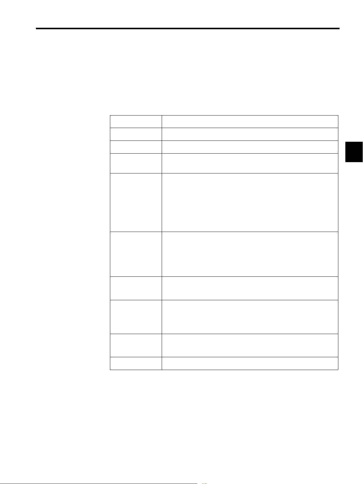
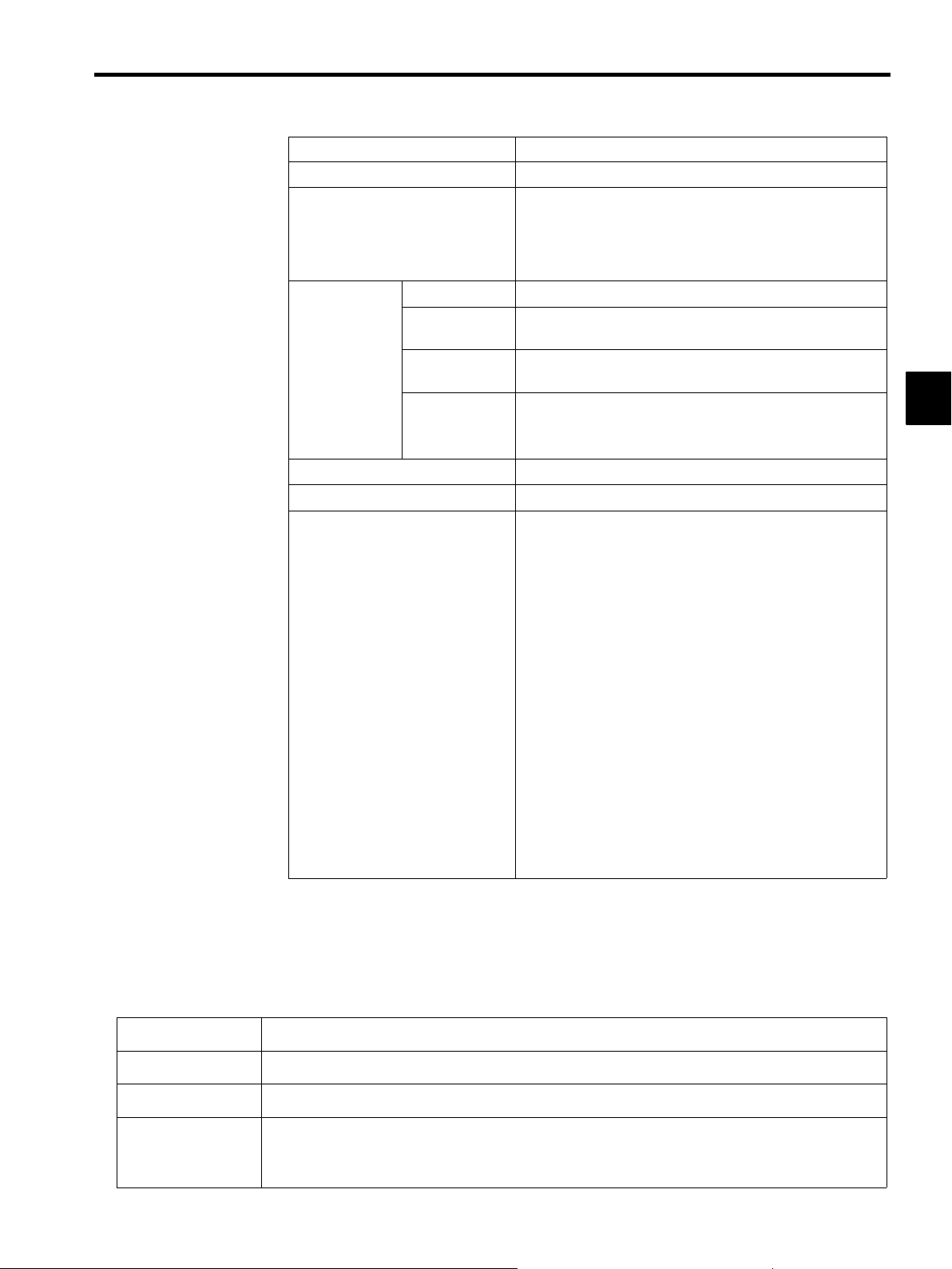
Refer to the following related manuals as required.
Thoroughly check the specifications, restrictions, and other conditions of the product before at-
tempting to use it.
Manual Name Manual Number Contents
MP9jjMachine Controller
Ladder Programming
User’s Manual
MP9jjMachine Controller
Motion Programming
User’s Manual
MP9jjMachine Controller
Programming Software
User’s Manual
SIEZ-C887-1.2 Describes the instructions used in MP9
ladder logic programming.
SIEZ-C887-1.3 Describes the motion instructions used by
MP9jjMachine Controllers.
Part 1:
SIEZ-C887-2.2−1
Part2:
SIEZ-C887-2.2−2
Describes the installation and operating procedures for the CP-717 Engineering Tool
Programming Software for MP9
Machine Controllers.
jj
jj
ix
Page 9

Using This Manual
Intended Audience
J
This manual is intended for the following users.
D Those responsible for estimating the MP930 system
D Those responsible for deciding whether to apply the MP930 system
D Those responsible for designing the MP930 system so that it can be mounted in the control and
operating panels
D Those responsible for making, inspecting, testing, adjusting, and maintaining the control and op-
erating panels in which the MP930 is mounted
Description of Technical Terms
J
In this manual, the following terms are defined as follows:
D PP = Programming Panel
D PC = Programmable Logic Controller
D “−− ” in “MOV [axis1]−−...” represents numeric data for axis 1.
x
Page 10
Safety Precautions
This section describes precautions that apply to ladder programming. Before programming, always
read this manual and all other documents provided to ensure correct programming. Before using the
equipment, familiarize yourself with equipment details, safety information, and all other precau-
tions.
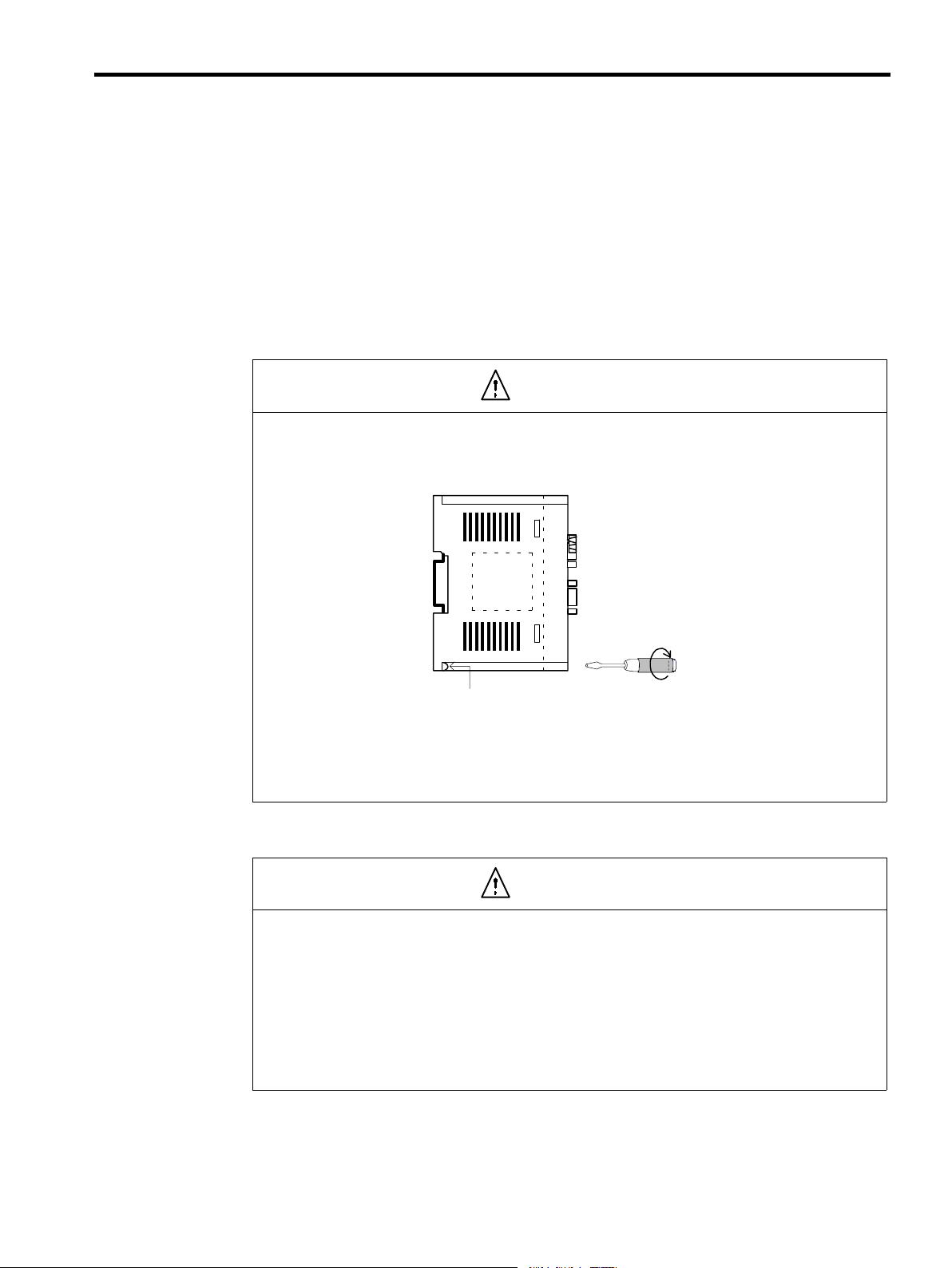
Installation
J
D Firmly tighten the Module mounting screws and terminal block mounting screws to
prevent them from loosening during operation.
Loose screws may result in a malfunction of the MP930.
Safety Precautions
Caution
Module mounting screw (M4, Phillips head)
D Be sure to turn OFF the MP930 before installing it.
D Insert the connectors of the cables that are to be connected to the MP930 and secure them well.
Incorrect insertion of the connectors may result in a malfunction of the MP930.
Wiring
J
Caution
D Always connect a power supply that meets the given specifications.
Connecting an inappropriate power supply may cause fires.
D Wiring must be performed by qualified personnel.
Incorrect wiring may cause fires, product failure, or malfunctions.
D Do not accidentally leave foreign matter such as wire chips on the Mounting Base or in
the Module when wiring.
This may cause fires, failures, and malfunctions.
xi
Page 11
Mandatory
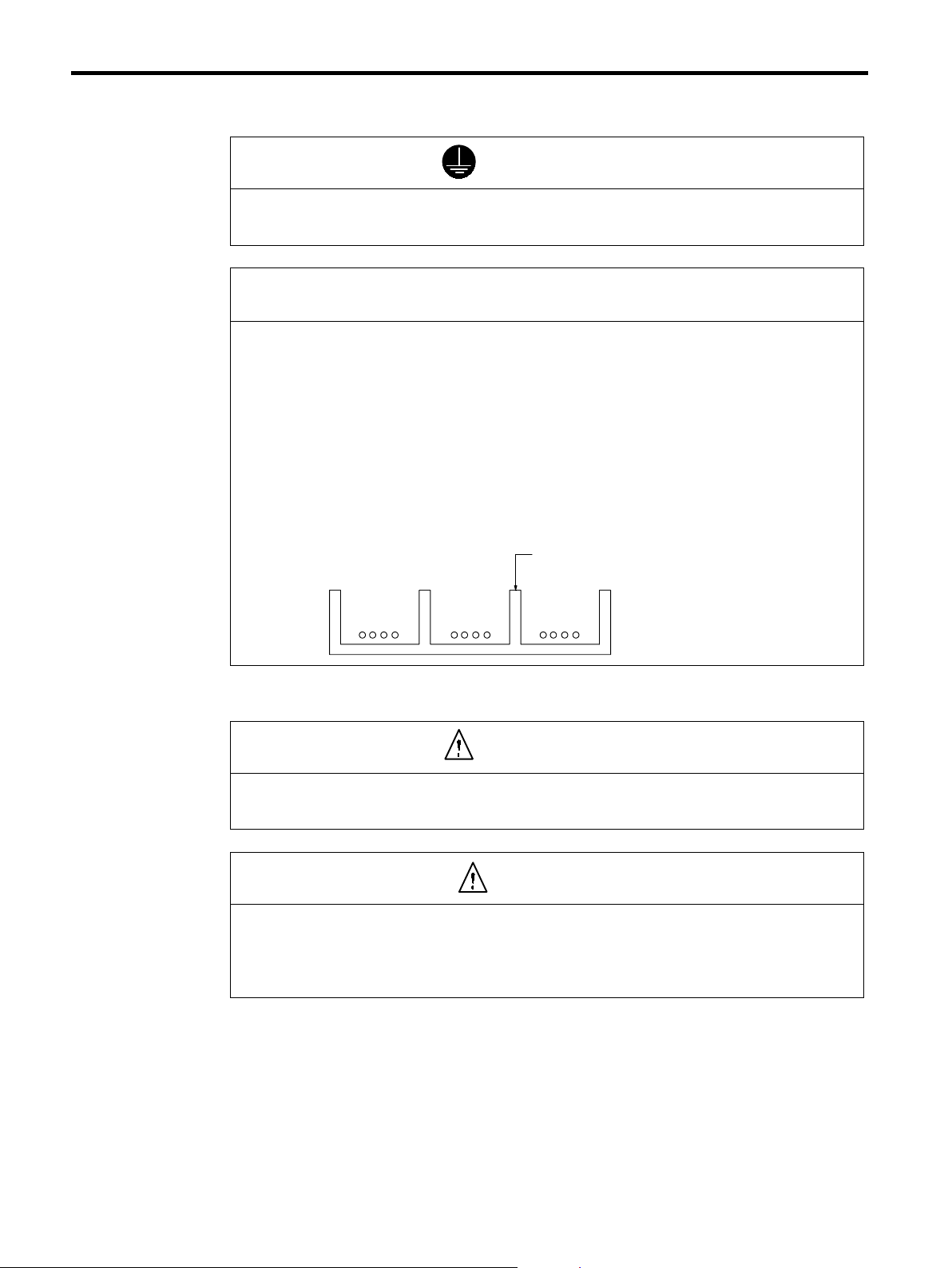
D Always use the ground the FG terminal to a ground resistance 100 Ω or less.
Failure to ground the MP930 may result in electrical shocks or malfunctioning.
Select, separate, and lay external cables correctly.
D Consider the following items when selecting the I/O signal lines (external cables) to connect the
MP930 Module to external devices.
S Mechanical strength
S Noise interference
S Wiring distance
S Signal voltage, etc.
D Separate the I/O signal lines from the power lines both inside and outside the control panel to re-
duce the influence of noise from the power lines.
If the I/O signal lines and power lines are not separated properly, malfunctioning may result.
Example of Separated External Cables
Power
circuit
cables
General
control circuit cables
Steel separator
Digital I/O
signal
cables
J Application Precautions
WARNING
D Do not touch any Module terminals when the system power is ON.
There is a risk of electrical shock.
Caution
D Do not attempt to modify the MP930 programs, force outputs, switch between RUN and STOP, or
performed other similar operations while the MP930 is operating without knowing the direct and
indirect consequences of the operation.
Incorrect programming or operation may damage the equipment or cause an accident.
xii
Page 12
Safety Precautions
J Maintenance Precautions
WARNING
D Make sure that the polarity of the Module’s built-in battery is correct. The battery must be installed
correctly and must not be charged, disassembled, heated, thrown into fire, or short-circuited.
Improper handling may cause the battery to explode or ignite.
Caution
D Do not attempt to disassemble or modify the MP930 Module in any way.
Doing so can cause fires, product failure, or malfunctions.
D The customer must not replace the built-in fuse.
If the customer replaces the built-in fuse, the MP930 Module may malfunction or break down.
The built-in fuse must always be replaced by Yaskawa service staff.
J General Precautions
Always note the following to ensure safe use.
D MP930 was not designed or manufactured for use in devices or systems directly related to human
life. Users who intend to use the product described in this manual for special purposes such as
devices or systems relating to transportation, medical, space aviation, atomic power control, or
underwater use must contact Yaskawa Electric Corporation beforehand.
D MP930 has been manufactured under strict quality control guidelines. However, if this product is to
be installed in any location in which a failure of MP930 involves a life and death situation or in a
facility where failure may cause a serious accident, safety devices MUST be installed to minimize
the likelihood of any accident.
D Drawings in this manual show typical product examples that may differ somewhat from the product
delivered.
D This manual may change without prior notice due to product improvements and specification
changes or for easier use. We will update the manual number of the manual and issue revisions
when changes are made. The revision number of the revised manual appears on the back of the
manual.
D Contact your nearest Yaskawa sales representative or the dealer from whom you purchased the
product and quote the manual number on the front page of the manual if you need to replace a
manual that was lost or destroyed.
D Contact your nearest Yaskawa sales representative or the dealer from whom you purchased the
product to order new nameplates whenever a nameplate becomes worn or damaged.
D Products modified by the customer are not covered by the Yaskawa warranty, nor does Yaskawa
assume any liability for injury or damage that may result from such modifications.
xiii
Page 13

1
MP930
This chapter describes the type of work that can be done by the MP930 sys-
tem, and gives an easy-to-understand overview of the MP930.
1.1 Overview of the MP930 1 - 2................
1.1.1 Appearance of MP930 Units 1 - 2...................
1.1.2 Features of the MP930 1 - 3.......................
1.2 Control Using the MP930 1 - 5...............
1.2.1 Types of Program 1 - 5............................
1.2.2 Ladder Logic Programs 1 - 6.......................
1.2.3 MC Programs 1 - 8...............................
1.2.4 Control Signals 1 - 9..............................
1
1.3 Operation from Programming Devices 1 - 10....
1.3.1 File Manager 1 - 10................................
1.3.2 System Information Definitions 1 - 11................
1.3.3 Programming 1 - 12...............................
1.3.4 Debugging and Monitoring 1 - 13....................
1.3.5 Printing 1 - 13.....................................
1-1
Page 14
1
MP930
1.1.1 Appearance of MP930 Units
1.1 Overview of the MP930
This section gives an overview of the MP930.
1.1.1 Appearance of MP930 Units
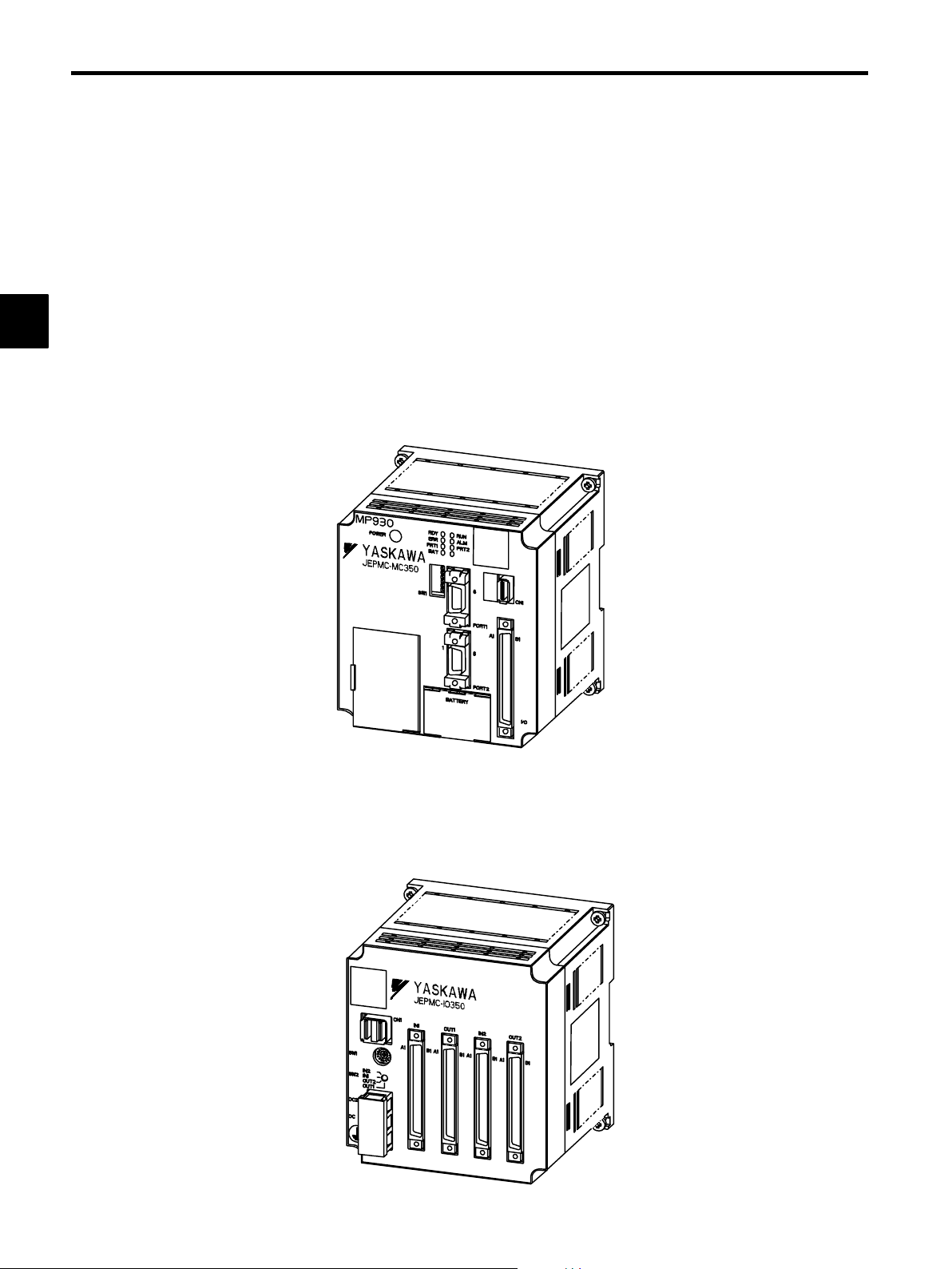
J Appearance of the MC Units
MC Unit Model No.: The follo win g illustr ation s ho ws the app ear anc e of the JEPMC-
MC350 Machine Controller Unit.
J Appearance of the I/O Units
I/O Unit Model No.: The follo win g illustr ation s ho ws the app ear anc e of the JEPMC-
IO350 I/O Unit.
1-2
Page 15
1.1.2 Features of the MP930
The MP930 has the following features:
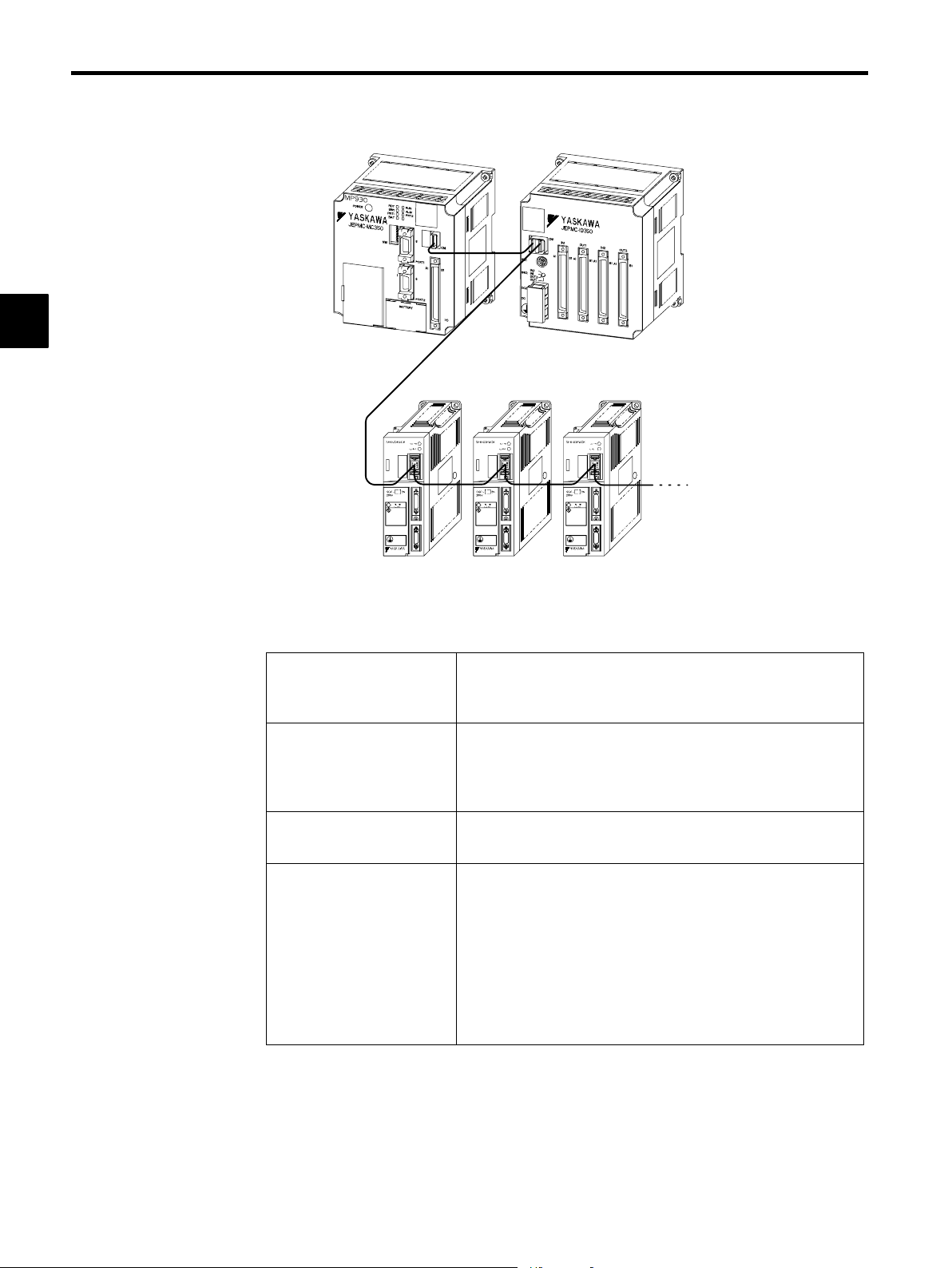
J The MP930 Machine Controller Unit is a micro machine controller
with a one−piece construction that integrates the power supply,
CPU, communications, and I/O.
The MP930 consists of an MC Unit, which provides both motion control functions and se-
quence control functions, and an I/O Unit. The servo amplifier and the I/O Unit are connected
to the MC Unit by a high-speed field network called MECHATROLINK. One MC Unit can
control a total of 14 servos and I/O Units.
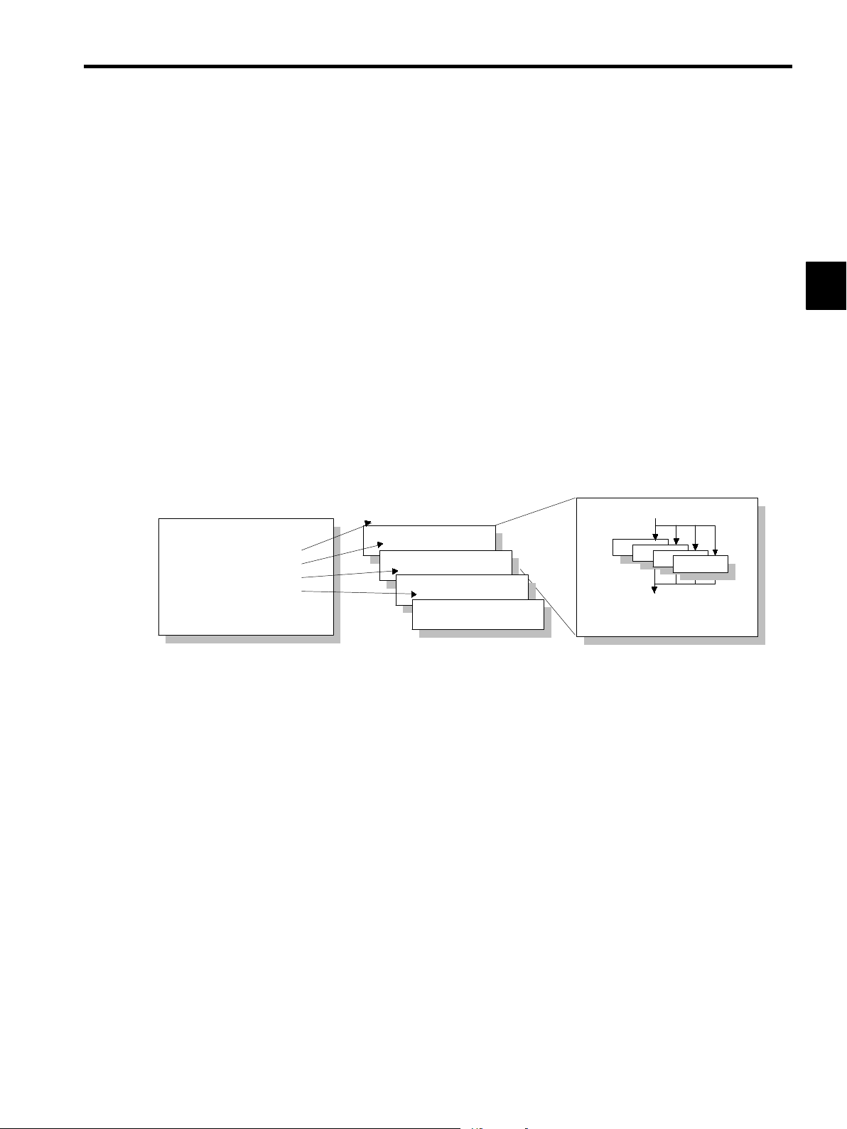
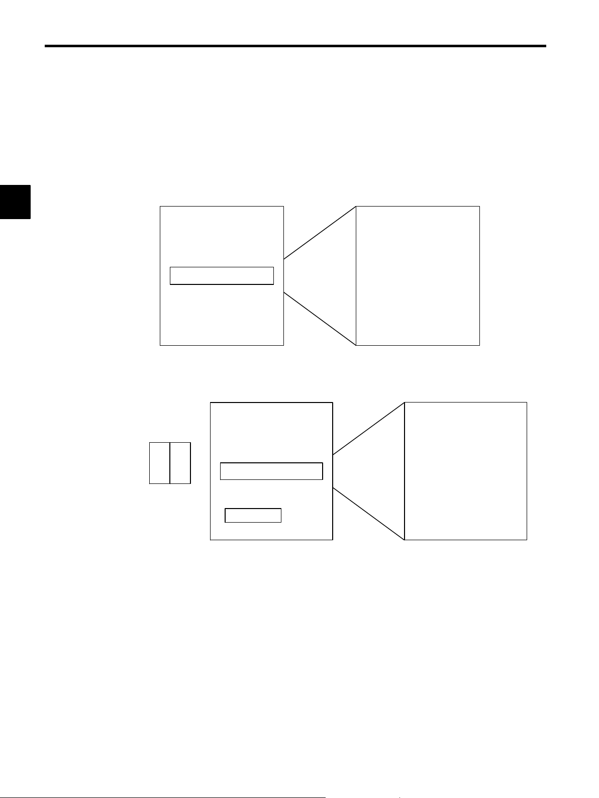
J Motion programs can be executed in parallel.
D Multiple motion programs can be executed in parallel.
D Four program blocks can be executed in parallel in one motion program.
1.1 Overview of the MP930
1
Ladder Logic Program
MSEE MPM001 DA0000
MSEE MPM002 DA0002
MSEE MPM003 DA0004
MSEE MPM004 DA0006
J Reduced Startup Time and High Reliability
The use of the MECHATROLINK high-speed field network reduces startup time.
D The control panel startup time is reduced.
D High reliability is achieved.
a) Shielded twisted-pair cable
b)Only three lines to wire
c) Half the number of connectors
Motion Program MPM001
Motion Program MPM002
Motion Program MPM003
Motion Program MPM004
Motion Program MPM001
PFORK S1, S2, S3, S4;
S1
S2
S3
S4
S5: PJOINT
1-3
Page 16
1
MP930
1.1.2 Features of the MP930
MC Unit I/O Unit
MECHATROLINK-compatible
Servopacks
J Wide Range of Motion Commands
Commands such as those shown in the following table can be used.
Complete Range of Move
Commands
Immediately Effective
Acceleration/Deceleration
Commands
Many Control Commands
POSITIONING, LINEAR INTERPOLATION, CIRCULAR INTERPOLATION, HELICAL INTERPOLATION, HOME RETURN,
SKIP, SET TIME POSITIONING, and EXTERNAL POSITIONING
ACCELERATION/DECELERATION TIME, S-CURVE TIME
CONSTANT, FEED SPEED SETTING, INTERPOLATION FEED
ACCELERATION/DECELERATION TIME SETTING, MAXIMUM INTERPOLATION FEED SPEED SETTING, and so on
I/O WAIT, IF statement, WHILE statement, Parallel Execution commands, Select Execution commands, and so on
Up to 14 stations
Wide Range of Math and
Logic Commands
Integer arithmetic commands: ADD, SUBTRACT, MULTIPLICATION, DIVISION
Floating-point commands: Addition, Subtraction, Multiply, Divide
Logic operations, SET BIT, RESET BIT
BCD-TO-BINARY, BINARY-TO-BCD
Trigonometric functions, inverse trigonometric functions, SQUARE
ROOT, and so on
1-4
Page 17
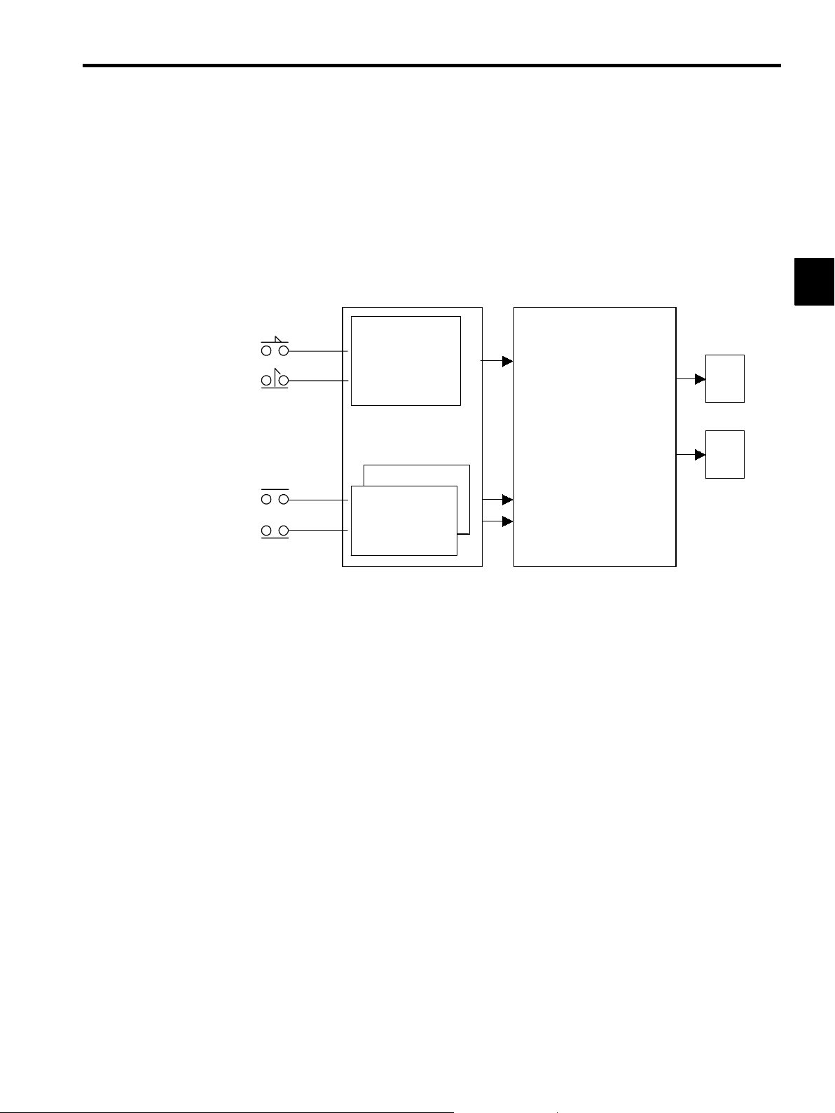
1.2 Control Using the MP930
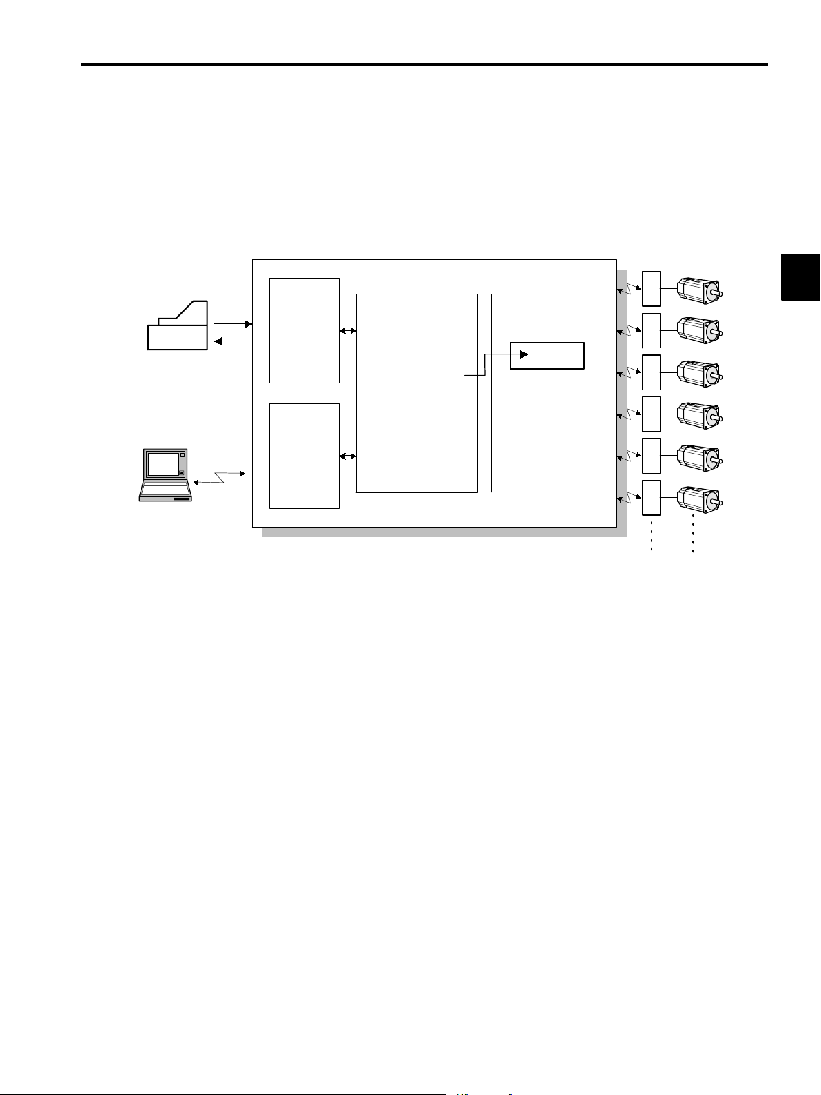
The MP930 is a machine controller with fully integrated sequence control and motion control. One
Controller simultaneously performs motion control and sequence control.
1.2 Control Using the MP930
I/O
processing
Operation panel
Programming Device
Figure 1.1 MP930 System Concept
1.2.1 Types of Program
Communications
control
Ladder logic program
Sequence control
MC program start
MSEE MPM001 DAXXX
MC program
Motion control
MPMxxx
.
.
.
.
.
.
.
Servo
amplifier
14 axes max.
Servomotor
1
Programs consist of ladder logic programs, which are designed mainly for sequence control,
and motion programs (called MC programs), which are designed mainly for servo control.
1-5
Page 18
MP930
Equival
20
K
f
ladderl
1.2.2 Ladder Logic Programs
1.2.2 Ladder Logic Programs
J Types of Drawing
A ladder logic program is a program used for coding the sequence logic for conditional control
and sequence control, and for coding the sequence logic that starts an MC program. The ladder
logic program is created as the basic unit called drawings (DWGs).
1
The following types of drawing are provided: Start drawing, high-speed scan drawings, low-
speed scan drawings, and user functions.
D Startup Drawings
Startup drawings are executed once when the power is turned ON. The logic used to set
constants and initialize operation is normally coded in these drawings.
D High-speed Scan Drawings
High-speed scan drawings are executed at regular intervals. The scan time is within the
range of 2 to 32 ms, and scan times can be set at 2-ms intervals. The circuits used to
the MC program are coded in the high
speed scan drawings.
-
start
D Low-speed Scan Drawings
Low-speed scan drawings are executed at regular intervals. The scan time is within the
range of 2 to 300 ms, and scan times can be set at 2-ms intervals. Sequence logic that does
not require high-speed processing, such as lamp output and display circuits, should be
coded in low-speed scan drawings.
D User Functions
User functions are defined as user commands in the coded drawings, using the commands
provided for the MP930. User functions can be used in startup drawings, high-speed scan
drawings, and low-speed scan drawings.
Types of Drawing Maximum Number
of Drawings
Startup Drawings
High-speed Scan Drawings
Low-speed Scan Drawings
User Functions
64 DWG.A
100 DWG.H
100 DWG.L
200 FUNC-xxx
Drawing and
Function Notation
1-6
Remarks
S 500 steps max. per drawing
S
S Security function can be set separately for
S Separate revision history or each drawing.
ent to
ic program memory
each drawing.
steps max. o
og-
Page 19
1.2 Control Using the MP930
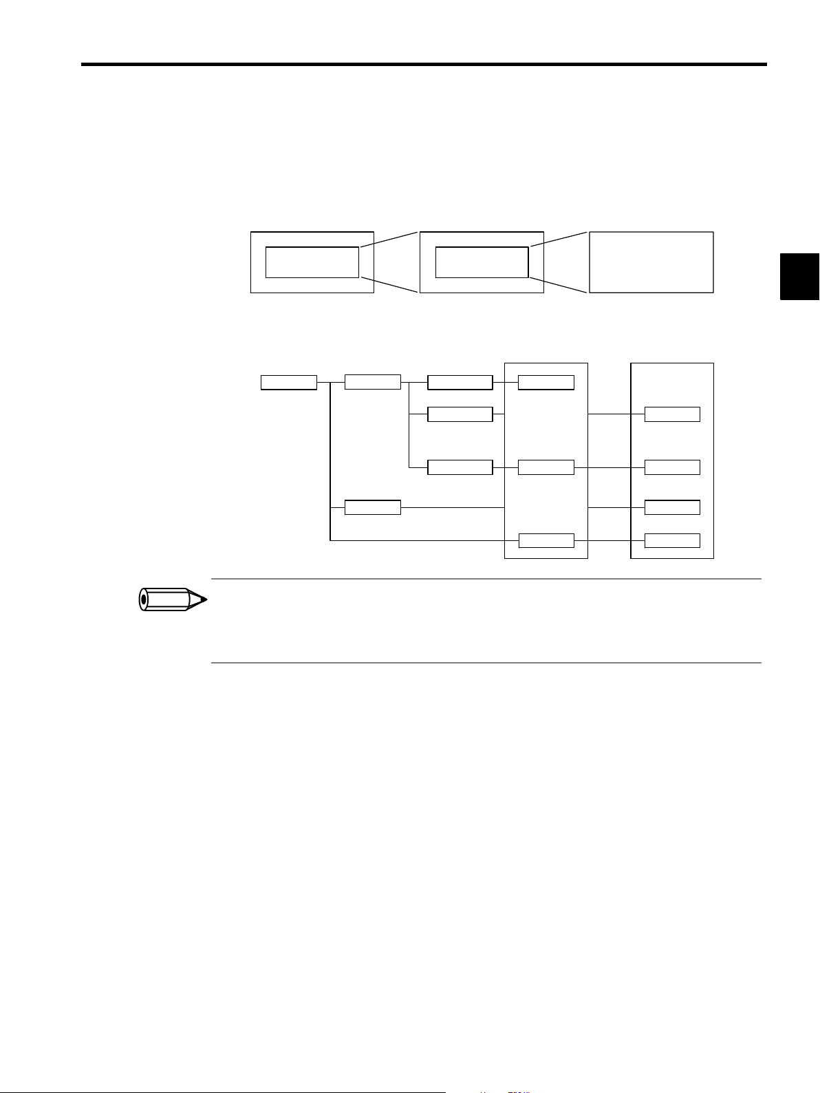
J Configuration of Drawings
Drawings can be arranged in up to three hierarchical levels: parent, child, and grandchild draw-
ings. These drawings are developed downward using the SEE instruction.
Functions can be started from any drawing.
INFO
SEE Child
drawing number
Parent drawing Child drawing Grandchild drawing
Parent drawing Child drawing Grandchild
DWG.X DWG.X01.01
DWG.X01
SEE Grandchild
drawing number
Motion programs
drawing
DWG.X01.01
.
.
DWG.X01.01
DWG.Xnn
1.
X is replaced by A, H, or L.
2. A motion program can be started only from an H drawing.
3.
Motion programs are started with the MSEE instruction.
MPM001
.
.
.
MPM002
.
.
.
MPM015
User constants
FUNC-001
.
.
FUNC-006
.
.
FUNC-032
.
.
FUNC-064
1
1-7
Page 20
1
MP930
1.2.3 MC Programs
1.2.3 MC Programs
An MC program codes the logic used for servo control in a motion control language. An MC
program is started using the MOTION PROGRAM CALL instruction (MSEE) in the ladder
logic program. There are two methods of designating an MC program: Direct designation of
the program number, and indirect designation of the number of the register in which the MPM
number is to be stored.
ABS;
MOTION PROGRAM
CALL instruction
MSEE MPM001 DA0000
↑
MPM number
MOV [X] _ [Y] _
MVS [X] _ [Y] _ F
IOW MB0001
MOV [X] _ [Y] _
.
.
.
Ladder logic program
0 3
Setting device
MC program
Figure 1.2 Starting an MC Program by Direct Designation
ABS;
MOTION PROGRAM
CALL instruction
MSEE MW00200 DA0000
MPM number
Ladder logic program
MW00200
MOV [X] _ [Y] _
MVS [X] _ [Y] _ F
IOW MB0001
MOV [X] _ [Y] _
Figure 1.3 Starting an MC Program by Indirect Designation
.
.
.
MC program
1-8
Page 21
1.2.4 Control Signals
There are two types of control signal: 1) Group input control signals, which are shared by
groups, such as automatic operation start signals and emergency stop signals, and 2) Axis input
signals, which are used by designated axes only, such as servo ON signals and JOG signals.
The signals (variables) to be used as control signals are allocated on the Group Definition
Screen.
1.2 Control Using the MP930
Control signals
:
:
Group input signals
Automatic operation start,
emergency stop, override,
operation mode, etc.
X axis input signals
X axis input signals
Servo ON
JOG
Other
MC program
ABS;
MOV [X] _ [Y] _
X axis
MOV [X] _ [Y] _ F _
IOW MB0001
MOV [X] _ [Y] _
Y axis
.
.
.
.
.
1
1-9
Page 22
1
MP930
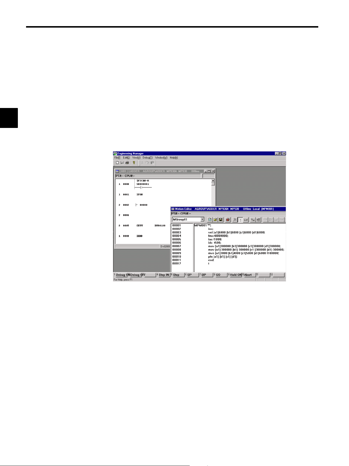
1.3.1 File Manager
1.3 Operation from Programming Devices
This section gives an overview of the types of operation that can be performed using peripheral
devices.
A computer running the CP-717 programming software for the ladder logic programs and motion
programs for the MP930 is called a “Programming Device.”
Communications with the Unit are enabled by connecting a Programming Device to the MEMO-
BUS port of the MP930 MC Unit using a special cable.
The following operations can be performed from the Programming Device.
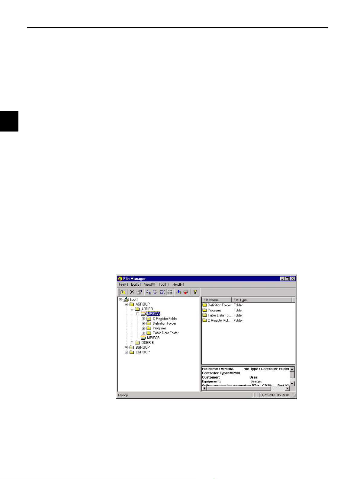
1.3.1 File Manager
The following folder and file management functions and file transfer functions are performed.
D File management
D User management
D File transfer
D Online/offline
D Logging off
D CPU control
1 -10
Page 23
1.3.2 System Information Definitions
The following information definitions are set.
D System definitions
D Scan time settings
D Application settings
1.3 Operation from Programming Devices
D Module configurations
D Failure monitoring
D Data traces
D Group definitions
D Motion parameters
1
1-11
Page 24
MP930
1.3.3 Programming
1.3.3 Programming
The following ladder logic programs and motion programs are edited.
D Main program creation
D Table format program creation
D Adjustment panel creation
1
D C registers
D Table data definitions
D Motion editor
1 -12
Page 25
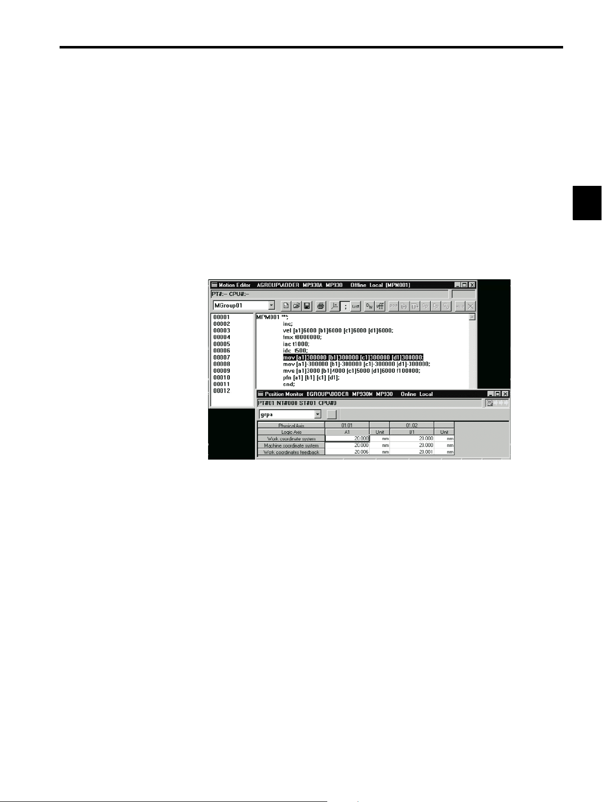
1.3.4 Debugging and Monitoring
The following functions are provided for debugging.
D Register list
D Adjustment panel
D Program monitor
1.3 Operation from Programming Devices
D Position monitor
D Task monitor
D Failure monitor
D Data trace monitor
1.3.5 Printing
1
The following data created for definitions and programming can be printed.
D Definitions
D Drawings and functions
D Motions
D Table data
D Registers
1 -13
Page 26

2
MP930 Specifications and System
Configuration
This chapter explains the MP930 Unit specifications, together with the
products used in the system configuration of the MP930.
2.1 Specifications 2 - 2.........................
2.1.1 General Specifications 2 - 2.......................
2.1.2 Hardware Specifications 2 - 3......................
2.1.3 Function List 2 - 4................................
2.2 Basic System Configuration 2 - 31.............
2.2.1 List of Basic Units 2 - 31............................
2.2.2 Basic System Configuration 2 - 32...................
2.2.3 Precautions on System Configuration 2 - 33..........
2.2.4 Programming Device 2 - 34.........................
2
2-1
Page 27

R
2
MP930 Specifications and System Configuration
2.1.1 General Specifications
2.1 Specifications
This section gives an overview of the specifications and functions of the MP930 Units.
2.1.1 General Specifications
J General Specifications of the MP930 Units
Table 2.1 lists the general specifications of the MP930 Units.
Table 2.1 General Specifications of the MP930 Units
Item Specifications
Environmental
Conditions
Electrical
Operating
Conditions
Mechanical
Operating
Conditions
Ambient Operating
Temperature
Storage Temperature
Ambient Operating
Humidity
Ambient Storage
Humidity
Pollution Level
Corrosive Gas
Operating Altitude
Noise Resistance
Vibration Resistance
0to55°C
−25 to 85 °C
30% to 95% RH (with no condensation)
5% to 95% RH (with no condensation)
Pollution level 1 (conforming to JIS B 3501)
There must be no combustible or corrosive gas.
2,000 m above sea level or lower
Conforming to JIS B 3502:
1,500 V (p-p) in either normal or common modes with
a pulse width of 100 ns/1µs and a rise time of 1 ns
(tested with impulse noise simulator)
Conforming to JIS B 3502:
10 to 57 Hz with single-amplitude of 0.075 mm
57 to 150 Hz with fixed acceleration of 9.8 m/s2(1G)
10 sweeps each in X, Y, and Z directions
(sweep time: 1 octave/min)
Shock Resistance
Installation
equirements
Ground
Cooling Method
2-2
Conforming to JIS B 3502:
2
Peak acceleration of 147 m/s
each in the ±X, ±Y, and ±Z directions
Ground to 100 Ω max.
Natural cooling
(15G) twice for 11 ms
Page 28
2.1.2 Hardware Specifications
J MP930 MC Unit Hardware Specifications
Table 2.2 lists the hardware specifications of the MP930 MC Unit.
Table 2.2 MC Unit Hardware Specifications
Item Specifications
2.1 Specifications
Name
Model Number
Memory
Communications
Ports
I/O Signals
Field Bus
Display Switch
*1, *2
MC Unit
JEPMC-MC350
2
Flash: 1 MB
RAM: 2 MB (battery backup)
RS-232C × 2 ports
Baud rate: 19.2 kbps
Female 9-pin D-sub connector (special pin assignments)
S MEMOBUS
S No protocol (custom)
S MELSEC
Inputs: 16 points
24 VDC (20.4 to 28.8 V)
5 mA, combined sinking/sourcing
Outputs: 16 points
24 VDC, 50 mA, sinking outputs
MECHATROLINK (high-speed field network)
Up to 14 servos and I/O stations can be connected.
Unit status indicators
I/O signal indicators
DIP switch for mode setting
Power Supply
Dimensions
*1. The I/O signal functions can be allocated.
*2. The Expansion I/O Unit can be used with MECHATROLINK communications.
24 VDC (20.4 to 28.8 V)
Rated current: 1 A; In-rush current: 50 A
120 (W) × 130 (H) × 105 (D) mm
2-3
Page 29
MP930 Specifications and System Configuration
2.1.3 Function Lists
J I/O Unit Hardware Specifications
Table 2.3 lists the hardware specifications of the I/O Unit.
Table 2.3 I/O Unit Hardware Specifications
2
Item
Name
Model Number
I/O Signals
MC Unit Interface
Unit Power
Supply
Dimensions
* The maximum rating per point is 100 mA (depending on derating conditions).
2.1.3 Function Lists
J MP930 Motion Control Function Specifications
Specifications
I/O Unit
JEPMC-IO350
Inputs: 64 points
24 VDC, 5 mA, combined sinking/sourcing
Outputs: 64 points
24 VDC, 50 mA, sinking outputs (all points ON) *
Signal connection method: Connector (FCN360 Series)
MECHATROLINK (high-speed field network)
24 VDC (20.4 to 28.8 V)
Rated current: 0.5 A; inrush current: 1 A
120 (W) × 130 (H) × 105 (D) mm
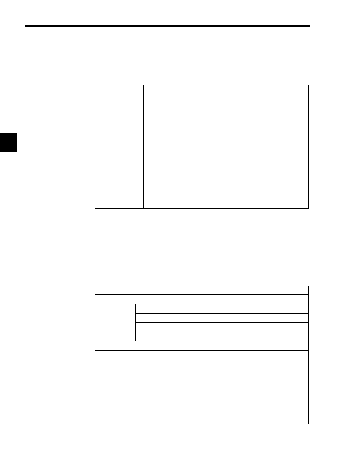
Table 2.4 lists the motion control function specifications for the MP930.
Table 2.4 MP930 Motion Control Function Specifications
Item
Number of Controlled Axes
Control
Specifications
Reference Unit
Reference Unit Minimum
Setting
Maximum Programmable Value
Speed Reference Unit
Acceleration/Deceleration Type
Override Function
PTP Control
Interpolation
Speed Control
Torque Limit
1 to 14 axes
Linear, rotary, infinite-length, and independent axes
Up to 14 linear axes, 2 circular axes, and 3 helical axes
None
Yes (According to parameter setting only)
mm, inch, deg, pulse
1, 0.1, 0.01, 0.001, 0.0001, 0.00001
−2147483648 to +2147483647 (signed 32-bit value)
mm/min, inch/min, deg/min, pulse/min
Linear, asymmetric, S-curve
Asymmetric acceleration/deceleration is not possible with
POSITIONING (MOV).
Positioning: 0.01% to 327.67% by axis
Interpolation: 0.01% to 327.67% by group
Specification
2-4
Page 30
Item Specification
Coordinate System
Zero Point Return
Programs
Applicable Servopack
Encoder
Command Words
Language
Number of
Tasks
Number of
Programs
Program
Capacity
2.1 Specifications
Rectangular coordinates
Four types
Dog + phase C, zero point limit switch, dog + zero point
limit switch, phase C
Home position setting function provided.
Special motion language
Multiple programs can be executed in parallel.
Up to 256
Equivalent to 80 Kbytes (characters)
(Can be increased or decreased according to the size of ladder
logic program used; maximum of 100 Kbytes.)
SGD-jjjN/SGDB-jjAN
Incremental or absolute
Axis Move Commands: 8 commands
MOV, MVS, MCW, MCC, ZRN, SKP, MVT, EXM
2
Basic Control Commands: 6 commands
ABS, INC, POS, PLN, MVM, PLD
Speed and Acceleration/Deceleration Commands: 7 commands
ACC, SCC, VEL, IAC, IDC, IFP, FMX
High-level Control Commands: 4 commands
PFN, INP, SNG, UFC
Control Commands: 10 commands
MSEE, TIM, IOW, END, RET, EOX, IF ELSE IEND,
WHILE WEND, PFORK JOINTO PJOINT, SFORK JOINTO SJOINT
Math and Sequence Control Commands: 32 commands
=, +, −, *, /, MOD, |, ^, &, !, (), S{}, R{}, SIN, COS, TAN,
ASN, ACS, ATN, SQRT, BIN, BCD, ==, <>, >, <, >=, <=,
SFR, SFL, BLK, CLR
J PLC Function Specifications
Table 2.5 lists the PLC function specifications.
Table 2.5 PLC Function Specifications
Item Specifications
Program Capacity
Control Method
Programming
Language
Equivalent to 4 Ksteps (varies according to amount of motion program used; 20 Ksteps max.)
Sequence: High-speed and low-speed scan methods
CP language
Ladder logic diagram: Relay circuit
Text-type language: Numeric operations, logic operations, etc.
2-5
Page 31

MP930 Specifications and System Configuration
2.1.3 Function Lists
Item Specifications
2
Scanning
User Drawings and
Functions
Motion Programs
Data Memory
Trace Memory
Memory Backup
Two scan levels: High-speed scan and low-speed scan
High-speed scan time setting: 2 to 32 ms (2 ms units)
Low-speed scan time setting: 2 to 300 ms (0.1 ms units)
Start drawings (DWG.A): 64 drawings max. Up to three hierarchical drawing levels
High-speed scan process drawings (DWG.H): 100 drawings max. Up to three hierarchical drawing levels
Low-speed scan process drawings (DWG.L): 100 drawings max. Up to three hierarchical drawing levels
Number of steps: Up to 500 steps per drawing
User functions: Up to 200 functions
Motion programs: Up to 256
Revision history of drawings and motion programs
Security function for drawings and motion programs
Common data (M) registers: 32 Kwords
System (S) registers: 1 Kwords
Drawing local (D) registers: Up to 16 Kwords per drawing
Drawing constant (#) registers: Up to 16 Kwords per drawing
Input (I) registers: 2 Kwords (including internal input registers)
Output (O) registers: 2 Kwords (including internal output registers)
Constant (C) registers: 4 Kwords
Data trace: 128 Kwords (32 Kwords × 4 groups), 16 points defined
Failure trace: 32 Kwords, 500 items defined
User memory: CMOS battery backup
Data Types
Register
Designation
Method
Instructions
Bit (relay): ON/OFF
Integer:
Double integer: −2147483648 to +2147483647
Real number: ± (1.175E − 38 to 3.402E + 38)
Register number: Direct designation of register number
Symbolic designation: Up to 8 alphanumeric characters (up to 200 symbols per drawing)
With automatic number or symbol assignment
Program control instructions: 14 instructions
Direct I/O instructions: 2 instructions
Relay circuit instructions: 14 instructions (including set and reset coils)
Logic operation instructions: 3 instructions
Numeric operation instructions: 16 instructions
Numeric conversion instructions: 9 instructions
Numeric comparison instructions: 7 instructions
Data manipulation instructions: 14 instructions
Basic function instructions: 10 instructions
Table data manipulation instructions: 11 instructions
DDC instructions: 13 instructions
System functions: 14 instructions
32768 to +32767
−
2-6
Page 32

J Motion Commands
Deceleration
Commands
Table 2.6 lists the motion commands.
Table 2.6 Motion Command List
2.1 Specifications
Classification
Axis Move
Commands
Basic Control
Commands
Command Function
MOV
MVS
MCC
MCW
ZRN
SKP
MVT
EXM
ABS
INC
POS
PLN
MVM
Positioning
Linear interpolation
Counterclockwise circular interpolation, Helical circular interpolation (counterclockwise)
Clockwise circular interpolation, Helical circular interpolation
(clockwise)
Zero point return
Skip
Set time positioning
External positioning
Absolute mode
Incremental mode
Current position set
Coordinate plane setting
Move on machine coordinate
2
Speed and
Acceleration/
Deceleration
Commands
High-Level
Control
Commands
PLD
ACC
SCC
VEL
IAC
IDC
IFP
FMX
PFN
INP
SNG
UFC
Program current position updating
Acceleration time change
S-curve time constant change
Set velocity
Interpolation acceleration time change
Interpolation deceleration time change
Interpolation feed speed ratio setting
Maximum interpolation feed speed setting
In-position check
Second in-position check
Ignore single block signal
User function call
2-7
Page 33

MP930 Specifications and System Configuration
2.1.3 Function Lists
Classification FunctionCommand
2
Control
Commands
MSEE
TIM
IOW
END
RET
EOX
IF
ELSE
IEND
WHILE
WEND
PFORK
JOINTO
PJOINT
SFORK
JOINTO
Subroutine call
Dwell time
I/O wait
Program end
Subroutine end
One scan wait
Branching commands
Repeat commands
Parallel execution commands
Selective execution commands
Sequence
Commands
SJOINT
=
+, −, *, /, MOD
|, ^, &, !
SIN, COS,
TAN, ASN,
ACS, ATN,
SQRT, BIN
BCD
==, <>, >, <,
>=, <=
SFR, SFL,
BLK, CLR
(),S{},R{}
Substitution
Arithmetic operations
Logic operations
Function commands
Numeric comparison commands
Data operation
Others
2-8
Page 34

J Motion Command Descriptions
Table 2.7 describes the motion commands.
Table 2.7 Motion Command Description
2.1 Specifications
Classification
Axis Move
Commands
Command Name Programming Format Function/Meaning
MOV
MVS
MCW
MCC
MCW
MCC
POSITIONING MOV [axis1] − [axis2] − ⋅⋅⋅;
(Up to 14 axes can be designated.)
LINEAR INTERPOLATION
CLOCKWISE CIRCULAR INTERPOLATION
COUNTERCLOCKWISE CIRCULAR
INTERPOLATION
CLOCKWISE HELICAL INTERPOLATION
COUNTERCLOCKWISE HELICAL INTERPOLATION
MVS [axis1] − [axis2] − ⋅⋅⋅F−;
(Up to 14 axes can be designated.)
MCW [axis1] − [axis2] − R−
F−; MCC [axis1] − [axis2] −
U− V− T− F−;
MCW [axis1] − [axis2] −U−V−
[axis3] −T− F−;
MCC [axis1] − [axis2]
−R−[axis3] −F−;
Executes positioning at rapid traverse
speed for up to 14 axes simultaneously.
In programming, replace “−” with the nu-
merical data for each axis.
Executes linear travel at interpolation feed
speed F for up to 14 axes simultaneously.
Executes circular interpolation at tangential
speed F for two axes simultaneously following radius R (or designated center point
coordinates).
With the center point coordinate designation, multiple circles can be designated
with T−.(T− can also be omitted.)
Moves three axes simultaneously in a combination of circular interpolation and linear
interpolation outside of the circular interpolation plane. Speed F will be the circular
interpolation tangential speed.
With the center point coordinate designation, the number of turns can be designated
with T−.(T− can also be omitted.)
2
ZRN
SKP
MVT
EXM
ZERO POINT RETURN
SKIP SKP [axis1]− [axis2]−
SET TIME POSITIONING
EXTERNAL POSITIONING
ZRN [axis1] − [axis2] − ⋅⋅⋅;
(Up to 14 axes can be designated.)
(Up to 14 axes can be designated.)
MVT [axis1]− [axis2]− ⋅⋅⋅ T−;
(Up to 14 axes can be designated.)
EXM [axis1]− D−;
2-9
Returns each axis to its zero point.
SS−;
⋅⋅⋅
If the SKIP signal turns ON during a linear
interpolation operation, skips the remaining movement and proceeds to the next
block.
Executes positioning by clamping the feed
speed so that travel can be completed at the
designated time.
When an external positioning signal is input while external positioning is being
executed, only the travel distance designated by “D−” is positioned with an incremental value, and then the next command
is executed.
Page 35

MP930 Specifications and System Configuration
C
2.1.3 Function Lists
Classification Function/MeaningProgramming FormatNameCommand
2
Basic Control
Commands
ABS
INC
POS
PLN
MVM
PLD
ABSOLUTE MODE ABS;
INCREMENTAL
MODE
CURRENT POSITION SET
COORDINATE
PLANE SETTING
MOVE ON MACHINE COORDINATE
PROGRAM CURRENT POSITION
UPDATE
INC;
POS [axis1] − [axis2] − ⋅⋅⋅;
PLN [axis1][axis2]
MVM MOV [axis1]− [axis2]−;
or
MVM MVS [axis1]− [axis2]−;
PLD [axis1] − [axis2] − ⋅⋅⋅; Updates the program current position for
Treats all subsequent coordinate words as
absolute values.
Treats all subsequent coordinate words as
incremental values.
Changes the current values to the desired
coordinate values for up to 14 axes simultaneously. Subsequent move commands
use this new coordinate system.
Designates the coordinate plane to be used
for a command requiring a plane designation command.
Goes to the target position on the machine
coordinate system. The coordinate system
set automatically on completion of the zero
point return is called a machine coordinate
system. This coordinate system is not affected by the POS command.
axes shifted by manual intervention. Up to
14 axes can be designated.
Speed and
Acceleration/
Deceleration
ommands
ACC
SCC
VEL
IAC
IDC
IFP
FMX
ACCELERATION
TIME CHANGE
S-CURVE TIME
CONSTANT
CHANGE
SET VELOCITY VEL [axis1] − [axis2] − ⋅⋅⋅;
INTERPOLATION
ACCELERATION
TIME CHANGE
INTERPOLATION
DECELERATION
TIME CHANGE
INTERPOLATION
FEED SPEED RATIO SETTING
MAXIMUM INTERPOLATION FEED
SPEED SETTING
ACC [axis1] − [axis2] − ⋅⋅⋅;
SCC [axis1] − [axis2] −
IAC T−;
IDC T−;
IFP P−;
FMX T−;
⋅⋅⋅
Sets the acceleration time for linear acceleration/deceleration for up to 14 axes simultaneously.
;
Sets the time constant for moving average
acceleration/deceleration for up to 14 axes
simultaneously.
Sets the feed speed for up to 14 axes.
Sets the acceleration time for linear acceleration/decelerationforinterpolationtravel.
Sets the deceleration time for linear acceleration/decelerationforinterpolationtravel.
Designates the maximum feed % for the
speed designation during an interpolation
feed.
Sets the maximum speed during an interpolation feed.
The interpolation acceleration time is the
time from “0” until this speed is reached.
2 -10
Page 36

Classification Function/MeaningProgramming FormatNameCommand
2.1 Specifications
High-Level
Control
Commands
Sequence
Commands
PFN
INP
SNG
UFC
=
IN-POSITION
CHECK
SECOND IN-POSITION CHECK
IGNORE SINGLE
BLOCK SIGNAL
USER FUNCTION
CALL
SUBSTITUTE (Result) = (Arithmetic expres-
MVS [axis1] − [axis2] − ⋅⋅⋅
PFN;
or
PFN [axis1][axis2];
INP [axis1] − [axis2] −
SNG MVS [axis1] 100. [axis2]
200. F1000;
UFC Function_name
Input_data, Input_address,
Output_data;
sion)
;
⋅⋅⋅
Proceeds to the next block after the positioning commanded by the interpolation
travel command in the same block or a previous block enters the positioning completion range (parameter setting).
Proceeds to the next block after the positioning subsequently commanded by the
interpolation travel command with PFN
enters the second positioning completion
range.
A block with this command will be executed continuously, even in single-block operation mode.
SNG cannot be designated on its own.
Calls a function created by the user.
Substitutes operation results. Performs calculations from left to right (with no order
of priority).
2
+
−
:
/
MOD
ADD MW− =MW− +MW−;
MW− =MW− + 123456;
MW− = 123456 + MW−;
SUBTRACT MW− =MW−−MW−;
MW− =MW−−123456;
MW− = 123456 − MW−;
MULTIPLY MW− =MW− : MW−;
MW− =MW− : 123456;
MW− = 123456 : MW−;
DIVIDE MW− =MW−/MW−;
MW− =MW−/123456;
MW− = 123456/MW−;
REMAINDER MW− =MW−/MW−;
MW− = MOD;
Performs integer and real number addition.
Calculates combinations of integers and
real numbers as real numbers.
Performs integer and real number subtraction. Calculates combinations of integers
and real numbers as real numbers.
Performs integer and real number multiplication. Calculates combinations of integers and real numbers as real numbers.
Performs integer and real number division.
Calculates combinations of integers and
real numbers as real numbers.
When programmed in the next block after
a division, MOD stores the remainder in
the designated register.
2-11
Page 37

MP930 Specifications and System Configuration
2.1.3 Function Lists
Classification Function/MeaningProgramming FormatNameCommand
2
Sequence
Commands
|
^
&
!
()
S{ }
R{ }
OR (logical OR) MB− =MB− |MB−;
MB− =MB− |1;
MW− =MW− |MW−;
MW− =MW− | H00FF;
XOR (logical exclusive OR)
AND (logical AND) MB− =MB− &MB−;
NOT (logical complement)
PARENTHESES MW− =MW− & (MW− |
SET BIT S{MB−}=MB− &MB−;
RESET BIT R{MB−}=MB− &MB−;
MW− =MW− ^MW−;
MW− =MW− ^ H00FF;
MB− =MB− &1;
MW− =MW− &MW−;
MW− =MW− & H00FF;
MB− = !MB−;
MB− = !1;
MW− = !MW−;
MW− = !H00FF;
MW−);
Performs bit/integer logical OR.
Performs integer logical exclusive OR.
Performs bit/integer logical AND.
Performs bit/integer logical complement
(inverts bits).
The logical arithmetic expression inside
parentheses is calculated first.
If the logical operation result is “true,” the
designated bit turns ON. The designated bit
does not turn OFF, even if the logical operation result is “false.”
If the logical operation result is “true,” the
designated bit turns OFF. The designated
bit does not turn ON, even if the logical
operation result is “false.”
SIN
COS
TAN
ASN
ACS
SINE SIN (MW−);
SIN (90);
COSINE COS (MW−);
COS (90);
TANGENT TAN (MF−);
TAN (45.0);
ARC SINE ASN (MF−);
ASN (45.0);
ARC COSINE ACS (MF−);
ACS (90.0);
Obtains the sine of the integer or real number (deg), and returns a real value.
Obtains the cosine of the integer or real
number (deg), and returns a real value.
Obtains the tangent of the real number
(deg), and returns a real value.
Obtains the arc sine of the real number
(deg), and returns a real value.
Obtains the arc cosine of the real number
(deg), and returns a real value.
2 -12
Page 38

Classification Function/MeaningProgramming FormatNameCommand
2.1 Specifications
Sequence
Commands
ATN
SQRT
BIN
BCD
==
<>
>
<
>=
ARC TANGENT ATN (MW−);
ATN (45);
SQUARE ROOT SQT (MW−);
SQT (100);
BCD-TO-BINARY BIN (MW−);
BINARY-TO-BCD BCD (MW−);
MATCH IF MW− ==MW−;
WHILE MW− ==MW−;
MISMATCH IF MW− <>MW−;
WHILE MW− <>MW−;
GREATER THAN IF MW− >MW−;
WHILE MW− >MW−;
LESS THAN IF MW− <MW−;
WHILE MW− <MW−;
GREATER THAN
OR EQUAL TO
IF MW− >= MW−;
WHILE MW− >= MW−;
Obtains the arc tangent of the integer or
real number (deg), and returns a real value.
Obtains the square root of the integer or
real number, and returns a real value.
Converts BCD data to binary data.
Converts binary data to BCD data.
Used in an IF or WHILE conditional expression. If the left side and right side
match, the condition is “true.”
Used in an IF or WHILE conditional expression. If the left side and right side do
not match, the condition is “true.”
Used in an IF or WHILE conditional expression. If the left side is greater than the
right side, the condition is “true.”
Used in an IF or WHILE conditional expression. If the left side is less than the
right side, the condition is “true.”
Used in an IF or WHILE conditional expression. If the left side is greater than or
equal to the right side, the condition is
“true.”
2
<=
SFR
SFL
BLK
CLR
LESS THAN OR
EQUAL TO
RIGHT SHIFT SFR MB− N− W−;
LEFT SHIFT SFL MB− N− W−;
BLOCK MOVE BLK MW− MW− W−;
CLEAR CLR MB− W−;
IF MW− <= MW−;
WHILE MW− <= MW−;
Used in an IF or WHILE conditional expression. If the left side is less than or equal
to the right side, the condition is “true.”
Shifts only the designated number of word
variables to the right.
Shifts only the designated number of word
variables to the left.
Moves the block (constant designation) beginning with the designated bit (word)
variable.
Sets the number of constants specified in
the variable group beginning with the designated bit (word) variable to OFF (“0”).
2 -13
Page 39

MP930 Specifications and System Configuration
2.1.3 Function Lists
Classification Function/MeaningProgramming FormatNameCommand
2
Control
Commands
MSEE
TIM
IOW
END
RET
EOX
IF
ELSE
IEND
WHILE
WEND
SUBROUTINE
CALL
DWELL TIME TIM T−;
I/O WAIT IOW MB− = = ***;
PROGRAM END END;
SUBROUTINE
RETURN
ONE SCAN WAIT EOX; Separates continuous sequence instructions
Branching commands
Repeat commands WHILE (conditional expres-
MSEE MPS− ;
RET;
IF (conditional expression) ;
(process 1)
ELSE;
(process 2)
IEND;
sion) ;
…
WEND;
Executes the MPS− subroutine.
Waits for the period of time specified by T,
and then proceeds to the next block.
Stops execution of the motion program until the conditional expression given in the
command is satisfied.
Ends the motion program.
Ends the subroutine.
and forces a wait of one scan before continuing execution.
Executes process 1 if the conditional expression is satisfied, and executes process 2
if the conditional expression is not satisfied.
Repeatedly executes WHILE to WEND
processing for as long as the conditional
expression is satisfied.
PFORK
JOINTO
PJOINT
SFORK
JOINTO
SJOINT
Parallel execution
commands
Selective execution
commands
PFORK label 1, label 2,…;
Label 1: Process 1
JOINTO label X
Label 2: Process 2
JOINTO label X
Label
S
S
Label X: PJOINT;
SFORK conditional expression
1? label 1, Conditional expression 2? label 2,…;
Label 1: Process 1
JOINTO label X
Label 2: Process 2
JOINTO label X
Label
S
S
Label X: SJOINT;
Executes the blocks designated by the labels in parallel. With a subroutine, a maximum of two labels can be designated. Also,
a motion command cannot be used in the
block designated by the second label.
END and RET cannot be used during parallel execution processing.
Executes process 1 if conditional expression 1 is satisfied, and executes process 2 if
the conditional expression 2 is satisfied.
2 -14
Page 40

J Ladder Instructions
Table 2.8 lists the ladder instructions.
Table 2.8 Ladder Instructions
2.1 Specifications
Type of Instruction Word
Instructions with [ ]
Program Control Instructions
Direct I/O Instructions
Relay Circuit Instructions
Logic Operation Instructions
Numeric Operation Instructions
Numeric Conversion Instructions
Number Comparison Instructions
Data Manipulation Instructions
Symbols
−
SEE, MSEE, FOR FEND, WHILE ON/OFF WEND, IFON/
IFOFF ELSE IEND, FSTART, FIN, FOUT, DEND, COMMENT, XCALL
INS, OUTS
S
,, ,,
T
,
,
T
s
,,
R
,,
s
,
AND (∧), OR (∨), XOR (¨)
,,⇒,+,−,++,−−, ×, ÷, MOD, REM, INC, DEC,
TMADD, TMSUB, SPEND
INV, COM, ABS, BIN, BCD, PARITY, ASCII, BINASC,
ASCBIN
<, ≦,=,¸, ≧, >, RCHK
ROTL, ROTR, MOVB, MOVW, XCHG, SETW, BEXTD,
BPRESS, BSRCH, SORT, SHFTL, SHFTR, COPYW,
BSWAP
2
Basic Function Instructions
DDC Instructions
Table Data Manipulation
Instructions
System Functions
SQRT, SIN, COS, TAN, ASIN, ACOS, ATAN, EXP, LN,
LOG
DZA, DZB, LIMIT, PI, PD, PID, LAG, LLAG, FGN, IFGN,
LAU, SLAU, PWM
TBLBR, TBLBW, TBLSRL, TBLSRC, TBLCL, TBLMV,
QTBLR, QTBLRI, QTBLW, QTBLWI, QTBLCL
COUNTER, FINFOUT, TRACE, DTRC-RD, FTRC-RD,
ITRC-RD, INC-WR, ICNS-RD, MSG-SND, MSG-RCV
2 -15
Page 41

MP930 Specifications and System Configuration
C
l
2.1.3 Function Lists
J Ladder Instructions and Standard System Functions
Table 2.9 lists the ladder instructions and standard system functions.
Table 2.9 Ladder Instructions and Standard System Functions
2
Type
Program
ontro
Instructions
Name Symbol Abbreviated
Instructions
Instructions with [ ] − − −
CHILD DRAWING
CALL
DRAWING END DEND END End of drawing (DWG)
MOTION PROGRAM CALL
FOR Structure FOR
WHILE Structure WHILE
SEE SEE Designate the child drawing number or the grandchild draw-
ing number to be referenced after SEE.
SEE H01
MSEE MSEE Designate the motion program number and the MSEE work
register address to be referenced after MSEE.
MSEE MPM001 DA00000
FOR Repeats execution statement 1
:
:
FEND
:
ON/OFF
:
WEND
WHILE
ON
OFF
FOR V = a to b by c
V: Can designate any integer register I or J.
a, b, c: Can designate an any integer value
(b>a>0,c>0).
FEND: End of FOR instruction.
Repeats execution statement 2
WEND: End of WHILE-ON/OFF instruction
Description
IF Structure -1, -2 IFON/IFOFF
:
ELSE
:
IEND
FUNCTION CALL
FUNCTION IN-
PUT
FUNCTION OUT-
PUT
COMMENT “nnnnnnn” ” A character string enclosed in quotation marks is treated as a
EXTENSION
PROGRAM CALL
FSTART FSTART
FIN FIN Function input instruction
FOUT FOUT Function output instruction
XCALL XCALL Calls an extension program.
IFON
IFOFF
ELSE
Conditional execution statement
IEND: End of IFON/IFOFF instruction
Calls a function.
Stores input data from the designated input register in the
function input register.
Stores output data from the function output register in the
designated output register.
comment.
2 -16
Page 42

2.1 Specifications
O
Type DescriptionAbbreviated
SymbolName
Instructions
Direct I/O
Instructions
INPUT
STRAIGHT
OUTPUT
INS INS INS MA00100
OUTS OUTS OUTS MA00100
STRAIGHT
Relay
NO CONTACT ][ No limit in a series circuit.
Circuit
Instruction
NC CONTACT ]/ No limit in a series circuit.
COIL @
SET COIL
RESET COIL
S
R
@S
@R
Executes the input and storage of data with interrupts disabled.
Executes the setting and output of data with interrupts disabled.
Bit designation of any register as a relay number is possible.
2
Bit designation of any register as a relay number is possible.
MB000000
MW0200 = 0001
MB000000
IFON
MB000010MB000000
S
MB000010MB000020
R
Logic
peration
Instructions
RISING PULSE ]P No limit in a series circuit.
Bit designation of any register as a relay number is possible.
FALLING PULSE ]N No limit in a series circuit.
Bit designation of any register as a relay number is possible.
10-MS ONDELAY TIMER
10-MS OFFDELAY TIMER
1-S ON-DELAY
TIMER
1-S OFF-DELAY
TIMER
Branching/convergence
T
T
s
s
[ON
[OFF
Set value: Timer register
T
Set value = any register or constant (setting unit: 10 ms)
Timer register = M or D register
[SON
[SOFF
Set value: Timer register
S
Set value = any register or constant (setting unit: 10 ms)
Timer register = M or D register
,.,. A branching or convergence symbol can be connected to any
of the above relay instructions.
AND < & Integer designation of any register or constant is possible.
OR > | Integer designation of any register or constant is possible.
XOR
¨
^ Integer designation of any register or constant is possible.
2 -17
Page 43

MP930 Specifications and System Configuration
Instructions
2.1.3 Function Lists
2
Type DescriptionAbbreviated
Numeric
Operation
INTEGER ENTRY ; Starts an integer operation.
REAL NUMBER
ENTRY
STORE ⇒ : Stores the operation result in the designated register.
ADDITION + + Ordinary numeric addition (with operation error)
SUBTRACTION − − Ordinary numeric subtraction (with operation error)
EXTENDED
ADDITION
EXTENDED SUBTRACTION
MULTIPLICATION
SymbolName
Instructions
;; Starts a real number operation.
++ ++ Closed numeric addition (without operation error)
−− −− Closed numeric subtraction (without operation error)
× *
⊦ MW00280 + 00100 ⇒ MW00220
MW00280 + 00100 ⇒ MW00220
⊦ MW00280 +00100 ⇒ MW00220
⊦ MW00280 −00100 ⇒ MW00220
0 → 32767 → −32768 → 0
0 → 32768 → −32767 → 0
For integer and long integers, use × and ÷ in combination.
DIVISION ÷ /
MOD MOD MOD Gets the remainder of the division result.
⊦ MW00100 × 0100 ÷ 00121
MOD ⇒ MW00101
REM REM REM Gets the remainder of the division result.
MF00200 REM 1.5⇒ MF00202
INCREMENT INC INC Adds 1 to the designated register.
INC MW00100
DECREMENT DEC DEC Subtracts 1 from the designated register.
DEC MW00100
ADD TIME TMADD TMADD Addition of hours, minutes, and seconds
TMADD MW00000, MW00100
SUBTRACT TIME TMSUB TMSUB Subtraction of hours, minutes, and seconds
TMSUB MW00000, MW00100
SPEND TIME SPEND SPEND Calculates the elapsed time between two times.
SPEND MW00000, MW00100
2 -18
Page 44

2.1 Specifications
Instructions
C
00000
10000
Type DescriptionAbbreviated
SymbolName
Instructions
Numeric
SIGN INVERSION INV INV
Conversion
1’S COMPLE-
COM COM
MENT
ABSOLUTE VAL-
ABS ABS
UE CONVERSION
BINARY CON-
BIN BIN
VERSION
BCD CONVER-
BCD BCD
SION
PARITY CON-
PARITY PARITY Calculates the number of binary bits that are ON.
VERSION
ASCII CONVER-
ASCII ASCII The designated character string is converted to ASCII code
SION 1
⊦ MW00100 INV
If MW00100 = 99, the operation result = −99.
⊦ MW00100 COM
If MW00100 = FFFFH, the operation result = 0000H.
⊦ MW00100 ABS
If MW00100 = −99, the operation result = 99.
⊦ MW00100 BIN
If MW00100 = 1234H (hexadecimal), the operation result =
1234 (decimal).
⊦ MW00100 BCD
If MW00100 = 1234 (decimal), the operation result = 1234H
(hexadecimal).
If MW00100 = F0F0H, the operation result = 8.
and substituted in the register.
MW00200 “ABCDEFG”
2
Numeric
omparison
Instructions
ASCII CONVERSION 2
BINASC BINASC Converts 16-bit binary data to 4-digit hexadecimal ASCII
code.
BINASC MW00100
ASCII CONVERSION 3
ASCBIN ASCBIN Converts the numeric value indicated by a 4-digit hexadeci-
mal ASCII code to 16-bit binary data.
ASCBIN MW00100
< < <
≦ ≦
= = =
<=
MW
MB000010
IFON
<
MB000010
≠ ≠ <>
≧ ≧
>=
> > >
RANGE CHECK RCHK RCHK Checks whether or not the value in the A register is in range.
⊦ MW00100 RCHK −1000, 1000
2 -19
Page 45

MP930 Specifications and System Configuration
2.1.3 Function Lists
2
Type DescriptionAbbreviated
Data
Operation
Instructions
BIT ROTATION
LEFT and BIT
ROTATION
RIGHT
MOVE BITS MOVB MOVB Source Desti. Width
MOVE WORD MOVW MOVW Source Desti. Width
EXCHANGE XCHG XCHG Source1 Source2 Width
SET WORDS SETW SETW Desti. Data Width
BYTE-TO-WORD
EXPANSION
WORD-TO-BYTE
COMPRESSION
SymbolName
Instructions
ROTR
ROTL
BEXTD BEXTD Expands the byte data stored in the word registers into
BPRESS BPRESS Collects the lower bytes of the word data stored in the word
ROTR
ROTL
Example: ROTR
Bit-addr Count Width
ROTR MB00100A → N=1 W=20
MOVB MB00100A → MB00200A W = 20
MOVW MB00100 → MB00200 W = 20
XCHG MB00100 → MB00200 W = 20
SETW MW00200 D = 00000 W = 20
words.
BEXTD MW00100 to MW00200 B = 10
register area.
BPRESS MW00100 to MW00200 B = 10
BINARY SEARCH BSRCH BSRCH Retrieves the register position that matches the data within
the designated register range.
BSRCH MW00000 W = 20 D = 100 R = MW00100
SORT SORT SORT Sorts registers within the designated register range.
SORT MW00000 W = 100
BIT SHIFT LEFT SHFTL SHFTL Shifts the designated bit strings to the left.
SHFTL MB00100A N = 1 W = 20
BIT SHIFT RIGHT SHFTR SHFTR Shifts the designated bit strings to the right.
SHFTR MB00100A N = 1 W = 2
COPY WORD COPYW COPYW Copies the designated register range.
COPYW MW00100 → MW00200 W = 20
BYTE SWAP BSWAP BSWAP The upper and lower bytes of the designated word are
swapped.
BSWAP MW00100
2 -20
Page 46

2.1 Specifications
Type DescriptionAbbreviated
Basic
Function
Instructions
SQUARE ROOT SQRT SQRT Taking the square root of a negative number will result in the
SINE SIN SIN Input = degrees
COSINE COS COS Input = degrees
TANGENT TAN TAN Input = degrees
ARC SINE ASIN ASIN MF00100 ASIN
ARC COSINE ACOS ACOS MF00100 ACOS
ARC TANGENT ATAN ATAN MF00100 ATAN
EXPONENT EXP EXP MF00100 EXP
NATURAL LOGARITHM
SymbolName
Instructions
LN LN MF00100 LN
square root of the absolute value multiplied by −1.
MF00100 SQRT
MF00100 SIN
MF00100 COS
MF00100 TAN
e MF00100
log
(FM00100)
e
2
COMMON LOGARITHM
LOG LOG MF00100 LOG
log
(FM00100)
10
2 -21
Page 47

MP930 Specifications and System Configuration
I
2.1.3 Function Lists
2
Type DescriptionAbbreviated
DDC
nstructions
DEAD ZONE A DZA DZA
DEAD ZONE B DZB DZB
UPPER/LOWER
LIMIT
PI CONTROL PI PI
PD CONTROL PD PD
PID CONTROL PID PID
FIRST-ORDER
LAG
PHASE LEAD/
LAG
FUNCTION GENERATOR
INVERSE FUNCTION GENERATOR
SymbolName
Instructions
LIMIT LIMIT
LAG LAG
LLAG LLAG
FGN FGN
IFGN IFGN
⊦ MW00100 DZA 00100
⊦ MW00100 DZB 00100
⊦ MW00100 LIMIT −00100 00100
⊦ MW00100 PI MA00200
⊦ MW00100 PD MA00200
⊦ MW00100 PID MA00200
⊦ MW00100 LAG MA00200
⊦ MW00100 LLAG MA00200
⊦ MW00100 FGN MA00200
⊦ MW00100 IFGN MA00200
LINEAR ACCELERATOR/DECELERATOR 1
LINEAR ACCELERATOR/DECELERATOR 2
PULSE WIDTH
MODULATION
LAU LAU
SLAU SLAU
PWM PWM
⊦ MW00100 LAU MA00200
⊦ MW00100 SLAU MA00200
⊦ MW00100 PWM MA00200
2 -22
Page 48

2.1 Specifications
O
Type DescriptionAbbreviated
Table Data
peration
Instructions
TABLE READ TBLBR TBLBR TBLBR TBL1, MA00000, MA00100
TABLE WRITE TBLBW TBLBW TBLBW TBL1, MA00000, MA00100
ROW SEARCH TBLSRL TBLSRL TBLSRL TBL1, MA00000, MA00100
COLUMN
SEARCH
TABLE CLEAR TBLCL TBLCL TBLCL TBL1, MA00000
TABLE BLOCK
MOVE
QUEUE TABLE
READ
QUEUE TABLE
READ AND INCREMENT
QUEUE TABLE
WRITE
QUEUE TABLE
WRITE AND INCREMENT
SymbolName
Instructions
TBLSRC TBLSRC TBLSRC TBL1, MA00000, MA00100
TBLMV TBLMV TBLMV TBL1, TBL2, MA00000
QTBLR QTBLR QTBLR TBL1, MA00000, MA00100
QTBLRI QTBLRI QTBLRI TBL1, MA00000, MA00100
QTBLW QTBLW QTBLW TBL1, MA00000, MA00100
QTBLWI QTBLWI QTBLWI TBL1, MA00000, MA00100
2
QUEUE POINTER
CLEAR
QTBLCL QTBLCL QTBLCL TBL1
2 -23
Page 49

MP930 Specifications and System Configuration
2.1.3 Function Lists
2
Type DescriptionAbbreviated
Standard
System
Functions
DATA TRACE
READ
TRACE TRACE TRACE Data trace execution control
FAILURE TRACE
READOUT
SEND MESSAGE MSG-SND MSG-SND Sending a message from a Communications Module
RECEIVE MESSAGE
COUNTER COUNTER COUNTER Increments or decrements a counter.
FIRST-IN FIRSTOUT
INVERTER
TRACE READ
INVERTER
CONSTANT
WRITE
SymbolName
Instructions
DTRC-RD DTRC-RD Data readout from data trace memory to user memory
FTRC-RD FTRC-RD Data readout from failure trace memory to user memory
MSG-RCV MSG-RCV Receiving a message from a Communications Module
FINFOUT FINFOUT First-in, first-out
ITRC-RD ITRC-RD Reads inverter trace data to store it in user register.
ICNS-WR ICNS-WR Writes inverter constant.
INVERTER
CONSTANT
READ
ICNS-RD ICNS-RD Reads inverter constant to register.
2 -24
Page 50

2.1 Specifications
Hard
Definiti
Confi
J Program Development Support Tool Function Specifications
Table 2.10 lists the program development support tool specifications.
Table 2.10 Program Development Support Tool Specifications
Item
Basic
ware
Basic
Software
Printer
Functions File Manager
Model
CPU
Main Storage
Display
Resolution
HDD
Pointing Device
Operating System
System
ons
Specifications
IBM PC/AT or compatible
Pentium 133 MHz or better, or equivalent
64 MB min.
640 × 480 min.
(800 × 600 min. recommended)
200 Mbytes min. of unused capacity is required.
PS/2 interface
Windows 95
Windows 95-compatible
File management
User management
File transfer
System definitions
Scan time settings
2
Unit
guration
Definitions
Application information settings
Failure monitoring
Data traces
Group definitions
Motion parameters
Configuration definitions
General-purpose serial definitions
Local I/O definitions
MECHATROLINK definitions
2 -25
Page 51

MP930 Specifications and System Configuration
P
P
2.1.3 Function Lists
Item Specifications
2
Functions Tools
Document
Sequence
rogramming
Adjustment Panel
Creation
Table Data
Definitions
Register lists
Cross references
Disable lists
Register number searches and replacements
Comment lists
Source conversions
Printing
Property settings
Main program creation
Table format program creation
Adjustment panel creation
C register creation
Table data creation
Motion
rogramming
Motion program editor
Position monitor
Task monitor
Motion alarm
2 -26
Page 52

J Program Development Support Tool Function List
Inf
Table 2.11 lists the program development support tool functions.
Table 2.11 Program Development Support Tool Functions
2.1 Specifications
Lop−level
Function
File Management
Intermediate
Functions
File management
User management
File transfer
Lower−level Functions
Name change
New PLC registration
PLC information change
Folder/file delete
CPU logon/logoff
Online/offline
CPU status switching
Drawing/function program editing
Latest information update
User management
Default user settings
Batch transfer
Individual transfer
2
System
ormation
Definitions
System definitions
Scan time settings
Application information setting
Consecutive transfer
Flash memory transfer
Multiple CPU transfer
System definitions
Definition data save
PLC selection
Scan time setting
Setting data save
Information setting
Information save
2 -27
Page 53

MP930 Specifications and System Configuration
Inf
Confi
2.1.3 Function Lists
2
Lop−level
Function
System
ormation
Definitions
Functions
Failure monitoring
Data traces
Lower−level FunctionsIntermediate
Failure definitions
Annunciator signal definitions
Failure status display
Failure occurrence display
Failure trace display
Definition data save
Definition data delete
Trace data definitions
Definition data save
Definition data delete
Trace data write
Trace data read
Data trace start
Unit
guration
Definitions
Group definitions
Motion parameters
Configuration definitions
General-purpose seri-
al port definitions
Trace data list display
Trend graph display
Group definitions
Save
Delete
Parameter setting
Save
Delete
Monitor
Configuration information setting
Save
Delete
Serial port setting
Save
Delete
2 -28
Page 54

2.1 Specifications
Confi
P
Lop−level
Function
Unit
guration
Definitions
Tools
Lower−level FunctionsIntermediate
Functions
Local I/O definitions
MECHATROLINK
definitions
Register list
Cross reference Cross reference execution
Disable list Disable coil retrieval
Register number retrievalandreplacement
Local I/O setting
Save
Delete
MECHATROLINK setting
Save
Delete
Register value monitor
Display format change
Register value change
Data input
Retrieval and replacement execution
2
Document
Sequence
rogramming
Comment list
Source conversion
Printing
Properties setting
Comment creation
Comment information update
Source conversion
Conversion rules
Print data setting
Print execution
Print status display
Print setting file editing
Print results sampling
Configuration information definitions
I/O definitions
Symbolic definitions
# register list
Change history
Properties setting data save
2 -29
Page 55

MP930 Specifications and System Configuration
P
C
Definiti
P
2.1.3 Function Lists
2
Lop−level
Function
Sequence
rogramming
Adjustment Panel
reation
Functions
Main program creation
Tableformat program
creation
Adjustment panel
creation
C register creation
Lower−level FunctionsIntermediate
Display mode switching
Command input
Program save
Program printing
Input mode switching
Display data input
Table editing
Table format program save
Input mode switching
Definition data input
Adjustment panel editing
Adjustment panel save
C register table list display
C register table creation
Table Data
ons
Motion
rogramming
Table data creation
Motion editor
Position monitor Current position coordinate display
Task monitor Task status display
Motion alarm Error status display
Table data list display
Column attribute setting
Table data setting
Motion properties
Import/Export
Text editing
Debugging
Position teaching
2 -30
Page 56

2.2 Basic System Configuration
This section gives an overview of the system configuration used by the MP930, together with the
various devices in this configuration.
2.2.1 List of Basic Units
Table 2.12 lists of the Units and other devices required in a system using the MP930.
2.2 Basic System Configuration
Table 2.12 List of Basic Units and Equipment
No. Name Description Outline
1
MC Unit MC350 Performs sequence and motion control.
2
I/O Unit IO350 Expansion I/O Unit
IN: 64 points, OUT: 64 points
3
MECHATROLINK
Cable 1
4
MECHATROLINK
Cable 2
5
MC Unit I/O Cable W5410 Connects the MC Unit and an external device.
6
Expansion I/O Unit
I/O Cable
7
Servopack SGD-jjjN
8
Servomotor − Select from a number of Series.
9
Motor Cable DP320081 Power cable for motor
10
Encoder Cable DB320089 Connects the motor encoder and the servo amp.
W6000 Used to expand the MC Unit.
Connected to the I/O Unit.
W6010 Connects the Expansion I/O Unit (or MC Unit)
and servo amp.
W5410 Connects the Expansion I/O Unit and an exter-
nal device.
Select a MECHATROLINK-compatible servo.
SGDB-jjAN
2
11
Software Package − Motion program and ladder logic program cre-
ation, etc.
12
Communications
Cable
13
DC power supply − 24 VDC power supply for the MC Unit, Ex-
W5311 Connects the MC Unit and Programming De-
vice.
pansion I/O Unit, and external I/O signals
2 -31
Page 57

MP930 Specifications and System Configuration
2.2.2 Basic System Configuration
2.2.2 Basic System Configuration
The following illustration shows the basic system configuration of the MP930.
2
Control panel
Computer
Programming Panel
24-V power supply
External I/O signals
Inputs: 16 points
Outputs: 16 points
Example:
D Automatic mode
D Manual mode
D Automatic operation start
D Automatic operation stop
D Alarm reset
D Alarm occurrence
D Automatic operation in
progress
D Manual operation in
progress
D Operation ready
...
MC Unit
SW1
RDY
ERR
PRT1
BAT
...
External I/O
signals
POWER
Inputs: 64 points
Outputs: 64 points
Example:
For manual operation
D SERVO ON
D JOG+
D JOG−
D STEP+
D STEP−
D HOME RETURN
RUN
ALM
PRT2
I/O Unit
Servopack
...
Servomotors
Besides being connected to the various switches and lamps
required to run the machine, output signals can also be
connected to external devices. Can be expanded according to
the number of signals.
CPU Module
Inputs: 16 points
Outputs: 16 points
I/O Module
Inputs: 64 points (max.)
Outputs: 64 points × 14 Modules
Figure 2.1 Basic System Configuration Diagram
2 -32
Input signals
Forward overtravel
Reverse overtravel
Zero point return
Deceleration limit switch
External latch signals
Output signals
Servo alarm
Brake interlock
Page 58

2.2.3 Precautions on System Configuration
The following precautions are on designing the system using the MP930.
D Use the connection cables specified by Yaskawa.
Various types of standard cable are provided by Yaskawa. When selecting cables, carefully
check the equipment for which the cables are to be used to avoid making any mistake.
D The customer must prepare the connection cables between the Expansion I/O Unit and the
servos.
D The Servopack that can be connected to the MP930 are the SGD- jjjN and the
SGDB-jjAN.
D The customer must provide the 24 VDC power supply.
D With the MP930, the overtravel signals, zero point return deceleration limit switch signals,
and external latch signals are connected to the servo amps.
2.2 Basic System Configuration
2
2 -33
Page 59

MP930 Specifications and System Configuration
2.2.4 Programming Device
2.2.4 Programming Device
Using the CP-717 Windows 95-compatible programming software increases the ease of programming, design efficiency, and the testing efficiency.
The CP-717 is provided with special functions, as support tools for the design, testing, and
maintenance of the sequence and motion programs.
CP-717
POWER
RDY
RUN
ERR
ALM
PRT1
PRT2
BAT
2
SW1
MP930
Standard computer
Figure 2.2 Programming Device
Basic Functions
The CP-717 has the five main functional areas, as shown in the following table.
Name Functions
File Manager
Definitions
Control functions for file management and online/offline control,
logoff, CPU control, etc.
Functions for defining system definitions, such as the Unit configuration
Programming
Debugging and Monitoring
Printing
Programming functions for sequence programs (ladder logic programs) and motion programs
Functions for program maintenance management: Register lists,
adjustment panels, program monitoring, position monitoring, task
monitoring, etc.
Printing functions for definitions, programming, debugging, monitoring, etc.
2 -34
Page 60

3
Basic System Operation
This chapter explains the basic operation of the MP930 system.
3.1 Operating Modes 3 - 2......................
3.1.1 Online Operating Mode 3 - 2.......................
3.1.2 Offline Stop Mode 3 - 2...........................
3.2 Start and Stop Sequences 3 - 3..............
3.2.1 DIP Switch Settings 3 - 3..........................
3.2.2 Start Sequence 3 - 5..............................
3.3 Power Failures 3 - 8........................
3.3.1 Power Failure Detection 3 - 8......................
3.4 User Programs 3 - 9........................
3.4.1 Drawings (DWGs) 3 - 9...........................
3.4.2 Execution Control of Parent Drawings 3 - 10..........
3.4.3 Motion Programming 3 - 14.........................
3.5 Functions 3 - 22.............................
3.5.1 Standard System Functions 3 - 22...................
3.5.2 Creating User Functions 3 - 23......................
3.6 Registers 3 - 28.............................
3.6.1 Register Designation Methods 3 - 28.................
3.6.2 Data Types 3 - 29.................................
3.6.3 Types of Register 3 - 33............................
3.6.4 Using Subscripts I and J 3 - 36......................
3.6.5 I/O and Registers in Functions 3 - 38.................
3.6.6 Register Ranges in Programs 3 - 39.................
3.7 Managing Symbols 3 - 40....................
3.7.1 Symbols in Drawings 3 - 40.........................
3.7.2 Symbols in Functions 3 - 41........................
3.7.3 Upward Linking of Symbols 3 - 42...................
3.7.4 Automatic Register Number Allocation 3 - 43..........
3
3-1
Page 61

3
Basic System Operation
3.1.2 Offline Stop Mode
3.1 Operating Modes
This section explains the online operating mode and the offline stop mode, both of which indicate
the MP930 operating status.
Operating mode Online operating mode
D RDY and RUN LEDs lit
D User program and I/O operation executing
Offline stop mode
D RDY or RUN LED not lit
D User program stopped
Figure 3.1 MP930 Operating modes
3.1.1 Online Operating Mode
When the power for the MP930 is turned ON, the RDY and RUN indicators will light
(the ERR and ALM indicators will not light) and the Unit will enter the online operating mode.
This means that the user program and I/O operations are being executed in the MP930 without
any errors or failures. If an alarm does occur, such as for an I/O conversion error or a user calculation error, the execution of the user program will not stop, and the online operating mode
will be maintained. The ALM indicator lights to indicate the occurrence of an error. For details
on the error content and the action to be taken, see Chapter 9 Troubleshooting.
3.1.2 Offline Stop Mode
The execution of the user program is stopped, and all outputs are reset (i.e., “0” is output for
all digital outputs). The RUN or RDY indicator will go OFF to indicate the status. Drawings
(DWG.H and DWG.L) are not executed in this status.
The Controller will be in the offline stop mode in the following four cases:
D When a scan time has not been set (see note 1)
D When the program memory has not been initialized (see note 1)
D When a serious failure, such as watchdog timer error, has occurred (see note 2)
D When a STOP operation has been performed from the CP-717 (see note 2)
D When the RUN/STOP switch has been set to OFF (STOP) and the power has been turned
ON (see note 3)
Note The above cases apply when a user program error occurs, or when there is a hard-
warefaultin the MP930. For detailsontheerrorcontent and theactiontobetaken,
see Chapter 9 Troubleshooting.
3-2
Page 62

3.2 Start and Stop Sequences
This section explains the start and stop sequences of the MP930. The methods of setting the DIP
switch, the types of self-diagnosis, and the indicator patterns are also explained.
3.2.1 DIP Switch Settings
The DIP switch on the CPU Module are used to control start and stop sequences. As shown in
Figure 3.2, there are six pins on the DIP switch on the CPU Module. Table 3.1 shows the function of each pin.
ON
→
123 456
3.2 Start and Stop Sequences
3
Figure 3.2
Table 3.1 DIP Switch Pin Functions
No. Name Setting Function Default Setting
FLASH
1
RUN
2
INIT
3
TEST
4
Not used
5
ON Used by the system
OFF −
ON User program operating
OFF User program stopped
ON Number 4 ON: Memory clear
OFF: Programming Panel
port default
OFF Online
ON Terminal (communications) mode
OFF Online
ON −
OFF −
Normally set to OFF.
Normally set to ON.
Normally set to OFF.
Normally set to OFF.
Normally set to OFF.
S.TST
6
ON Used by the system
OFF Online
3-3
Normally set to OFF.
Page 63

Basic System Operation
3.2.1 DIP Switch Settings
Memory Initialization
When the DIP switch is set according to the following procedure and the power is turned ON
or OFF, memory will be initialized, and the user programs and definition data will be deleted.
1 2 3 4 5
3
Turn OFF the
MP930 power.
Turn ON DIP
switch pins 3 and
4.
ON
→
123 456
Turn ON the power, and check that
the RDY and
RUN indicators
flash (about 3 seconds).
Turn OFF the
power, and return
the DIP switch
pins to their original settings.
ON
→
123 456
Turn ON the power again.
Always execute memory initialization if you remove the battery when the Module power supply is turned OFF.
3-4
Page 64

3.2.2 Start Sequence
The MP930 makes a number of determinations at startup. If an error is detected, the ERR indicator will flash and the error content will be indicated by the number of times the indicator
flashes. When the indicator is flashing, the CP-717 cannot be operated. For details on the error
content and the action to be taken, see Chapter 9 Troubleshooting. Table 3.2 shows the MP930
indicators.
Table 3.2 Indicators and Indicator Patterns
3.2 Start and Stop Sequences
Type
Normal
Error
Alarm
Indicator
RDY RUN ALM ERR BAT
ALM
Lit Unlit Unlit Unlit Unlit The user program is stopped.
Lit Lit Unlit Unlit Unlit The user program is executing normally.
Lit Lit Lit Lit Unlit Hardware reset status (while display is contin-
uing)
Unlit Unlit Unlit Unlit Unlit During initial execution (while display is con-
tinuing)
Unlit − Unlit Lit Unlit A serious error has occurred.
Unlit Unlit Unlit Flash-
ing
− − − − Lit Battery alarm
Lit Lit Lit Unlit Unlit
Unlit
Flashing once or twice: RAM error
1.
Flashing two or three times: ROM error
2.
3. Flashing three or four times: Peripheral
LSI error
1. Calculation error
I/O error
2.
Meaning
3
Other
Reported to the system (S) register (no indicator display)
Flashing
RDY and RUN flash repeatedly at the
same time.
Unlit Unlit Lit Unlit Unlit
Flashing
Unlit Unlit Unlit
3-5
Hardware status (power loss, RUN/STOP, test
mode, etc.)
Memory initialization has been completed for
the DIP switch settings.
Offline test mode
Page 65

Basic System Operation
3.2.2 Start Sequence
J MP930 Start Sequence and Basic Operation
Power ON
3
Calculated from time of
power failure and time of
power restoration
Defined on the CP-717
System Definition Screen
Test mode switch
= Test mode
= Normal mode
User memory
check
= Not damaged
Offline self-diagnosis
= Damaged
Program data:
Memory clear
Read calendar
(current value)
Time of power
failure
= 10 ms to n s * (power loss)
≧ n s (power failure) *
Report power failure
Designated start
= Continuous
Report continuous
operation
Start mode
= New
Report new operation
= Continuous
= New
Report power loss
Designated start
= Continuous
Report continuous
operation
= New
Startup self-diagnosis I/O output
(power failure data)
Detect RUN switch
Start watchdog timer
Execute DWG.A
Low-speed
scan
Input Online self-diagnosis
Execute DWG.L Execute DWG.H
Output
The time for power loss is defined on the CP-717 System Definition Screen.
*
High-speed
scan
Input
Output
Ground
3-6
Page 66

3.2 Start and Stop Sequences
The MP930 start sequence and basic operations are as follows:
1. Startup Self-diagnosis
The following operations are provided for startup self-diagnosis:
• Memory (RAM) read/write diagnosis
• System program (ROM) diagnosis
• Main processor (CPU) function diagnosis
• Numeric co-processor (FCPU) function diagnosis
If an error occurs in the diagnostic result, the RDY indicator will flash the specified number of times.
2. Online Self-diagnosis
The following operations are provided for online self-diagnosis:
• System program (ROM) diagnosis
• Main processor (CPU) function diagnosis
• Numeric co-processor (FCPU) function diagnosis
3
If an error occurs in the diagnostic result, the RDY indicator will flash the specified number of times.
3. New Operation Start
Set the operation method for “New Operation” on the CP-717 System Definition Screen.
When the system is next started, the new operation will be used to start. Unlike a continuous operation start, self-diagnostic processing is performed before DWG.A is executed.
4. Continuous Operation Start
a) Set the operation method for “Continuous Operation” on the CP-717 System Defini-
tion Screen. When the system is next started, the continuous operation will be used to
start. Unlike a new operation start, no self-diagnostic processing is performed. Therefore, the startup time for drawing execution is shortened.
b)If the RUN switch is ON (RUN) or if it turns ON (RUN) from OFF (STOP), the CPU
starts the watchdog timer and then executes DWG.A.
c) Once the execution of DWG.A has been completed, the scan is started. The initial scan
is executed only after the time for the high-speed or low-speed scan has elapsed following the completion of DWG.A. System inputs and outputs are executed from the first
scan.
5. Operation Stop
The MP930 stops operating in the following cases:
• When the power supply is interrupted (see *1)
• When a power failure has occurred (see *1)
• When a fatal error has occurred (see *2)
• When a STOP operation has been performed from the CP-717 (see *3)
The MP930 can be restarted only by turning ON the power again.
*1.
*2. Restart the system by turning the power ON and OFF. The cause of the error can
be ascertained by the indicator status.
*3. Restart the system by performing a RUN operation from the CP-717.
3-7
Page 67

3
Basic System Operation
3.3.1 Power Failure Detection
3.3 Power Failures
This section explains the processing when an MP930 power failure occurs.
3.3.1 Power Failure Detection
Table 3.3 shows the start methods used when an MP930 power failure occurs.
The MP930 can select two types of startup: Continuous operation and new operation. The
selection of continuous operation or new operation is made on the CP-717 System Definition
Screen.
For details on the CP-717 operation method, refer to the MP9jj Machine Controller Pro-
gramming Software User’s Manuals (SIEZ-C887-2.2-1, SIEZ-C887-2.2-2).
Table 3.3 MP930 Start Modes
Length of Power
Failure
0to20ms
20 ms to Ns*
(Power loss)
Ns* or more
* Ns (power loss decision time) is defined on the CP-717 System Definition Screen.
Continuous Operation/
New Operation
− Operations continue.
When continuous operation is
selected
When new operation is
selected
When continuous operation is
selected
When new operation is
selected
After the CPU is reset, no self-diagnosis is
performed, and operations continue.
After the CPU is reset, self-diagnosis is
performed, and the new operation starts.
After the CPU is reset, no self-diagnosis is
performed, and operations continue.
After the CPU is reset, self-diagnosis is
performed, and the new operation starts.
Start Method
3-8
Page 68

3.4 User Programs
This section explains the basic operation of the MP930, such as the types of user program, the priority levels, and the execution processing methods.
3.4.1 Drawings (DWGs)
User programs are managed in units of programming called drawings, Each drawing is identified by a drawing number (DWG No.). These drawings serve as the basis of user programs.
The drawings include parent drawings, child drawings, grandchild drawings, and operation error drawings. Besides the drawings, there are functions that can be freely called from each
drawing, and motion programs that can be called only from H drawings.
3.4 User Programs
3
D Parent Drawings
Parent drawings are executed automatically by the system program when the execution
condition is established. See Table 3.4 for execution conditions.
D Child Drawings
Child drawings are executed by being called from a parent drawing using the SEE command.
D Grandchild Drawings
Grandchild drawings are executed by being called from a child drawing using the SEE
instruction.
D Operation Error Drawings
Operation error drawings are executed automatically by the system program when an operation error occurs.
D Functions
Functions are executed by being called from a parent, child, or grandchild drawing using
the FSTART instruction.
D Motion Programs
Motion programs can be called only from H drawings. They can be executed by being
called from a parent, child, or grandchild drawing using the MSEE instruction.
Types and Priority Levels of Parent Drawings
Parent drawings are classified by the first character of the drawing number (A, H, L) according
to the purpose of the process. The priority levels and execution conditions are as shown in Table
3.4.
3-9
Page 69

Basic System Operation
3.4.2 Execution Control of Parent Drawings
Table 3.4 Types and Priority Levels of Parent Drawings
3
Type of Parent
Drawing
DWG.A
Role of
Drawing
Startup process 1 Started when power is turned ON
Priority
Level
Execution Condition Number of
(executed once only when the
power is turned ON)
DWG.H
DWG.L
High-speed scan
process
Low-speed scan
process
2 Started at a fixed interval (executed
during each high-speed scan)
3 Started at a fixed interval (executed
during each low-speed scan)
Table 3.5 gives details of the number of drawings for each type of drawing.
Table 3.5 Details of Drawings
Drawing
Parent Drawing
Operation Error Drawing
Child Drawings
Grandchild Drawings
DWG.A DWG.H DWG.L
1 (A) 1 (H) 1 (L)
1 (A00) 1 (H00) 1 (L00)
Maximum total of 62
drawings drawings drawings
Number of Drawings
Maximum total of 98
Maximum total of 98
Drawings
64
100
100
3.4.2 Execution Control of Parent Drawings
Each drawing is executed based on its priority level, as shown in Figure 3.3.
Power ON
DWG.A
Startup drawing
During each high-speed scan During each low-speed scan
All outputs
All inputs
DWG.H
High-speed scan
process drawings
Figure 3.3 Execution Control of Parent Drawings
All outputs
All inputs
DWG.A
Low-speed scan
process drawings
Operation error
DWG.X00
Operation error
X: A, H, L
Continue with original process
IMPORTANT
Interrupt drawings cannot be used with the MP930.
3 -10
Page 70

3.4 User Programs
J Execution Scheduling of Scan Process Drawings
The scan process drawings are not executed simultaneously. As shown in Figure 3.4, they are
scheduled based on the priority level and are executed according to the schedule.
Low-speed scan
High-speed
scan
DWG.H
DWG.L
Ground*
High-speed
scan
High-speed
scan
High-speed
scan
IMPORTANT
: Executed
* Used for internal system processes, such as self diagnosis.
Figure 3.4 Execution Scheduling of Scan Process Drawings
Set the high-speed scan time as a multiple of 2 with a minimum of 2 ms.
1.
2. The low-speed scan process is executed in the unused time of the high-speed scan process. Therefore, as a
guideline, set a time that is twice the execution time of all the DWG.H drawings as the high-speed scan time.
J Hierarchical Arrangement of Drawings
Drawings are arranged in the following order: Parent drawing, child drawings, grandchild
drawings. A parent drawing cannot call a child drawing of a different type, and a child drawing
cannot call a grandchild drawing of a different type. A parent drawing also cannot directly call
a grandchild drawing. A child drawing is called from a parent drawing, and a grandchild draw-
ing is called from that child drawing. This is called the hierarchical arrangement of drawings.
3
3-11
Page 71
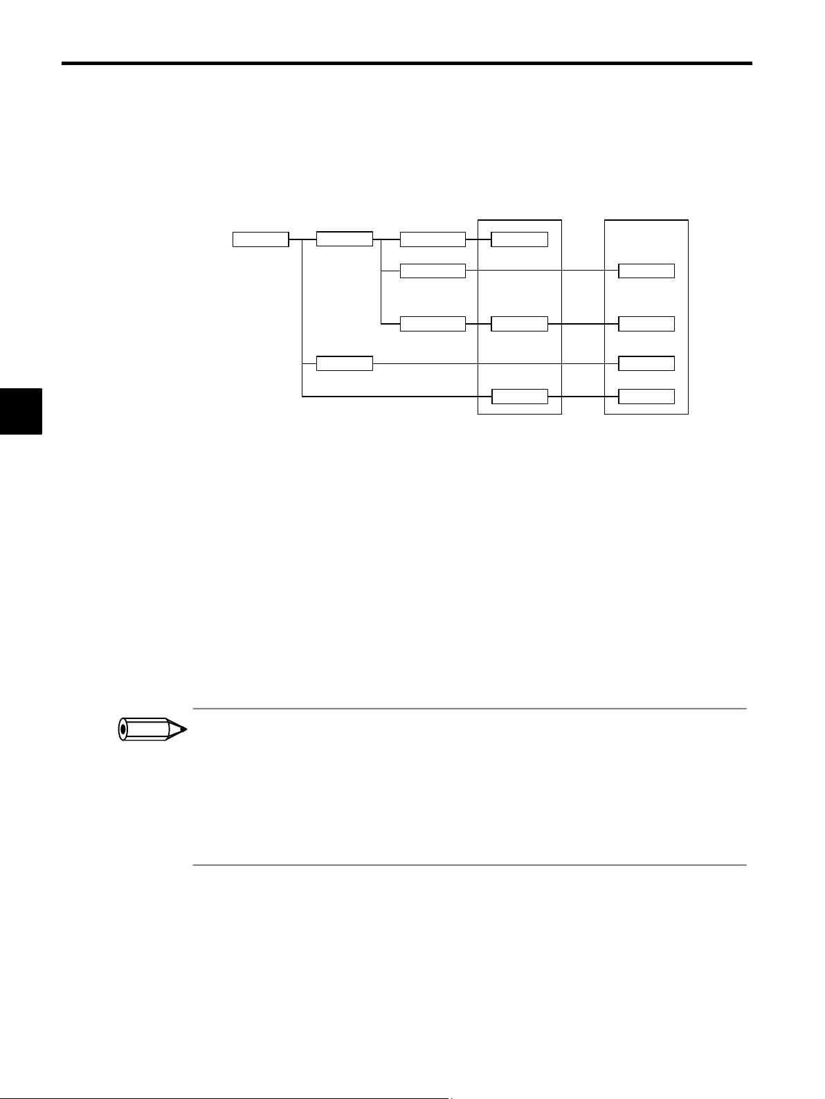
Basic System Operation
3.4.2 Execution Control of Parent Drawings
J Execution of Drawings
The user prepares each processing program with the parent drawing, child drawing, grandchild
drawing hierarchy, as shown in Figure 3.5.
3
Parent Drawing
DWG.X DWG.X01.01
Child Drawings Grandchild
Drawings
DWG.X01
Motion programs User functions
MPM001
.
DWG.X01.02
.
.
.
.
DWG.X01.03
MPM002
.
DWG.Xnn
Note Substitute A, H, or L for X.
Figure 3.5 Hierarchical Arrangement of Drawings
Note 1.
Aparentdrawingisexecutedautomaticallybythe system, because the execution condition is determined for each one. In other words, a parent drawing is
automatically called by the system. See Table 3.4 Types and Priority Levels of
Parent Drawings. The user can execute any child or grandchild drawing by
programminganinstructionthat calls a drawing(theSEEinstruction)in a parent or child drawing.
2. Functions can be called from any drawing. A function can also be called from
a function.
3. If an operation error occurs, the operation error drawing corresponding to the
drawing will be called.
4. Motion programs must be called from H drawings using the MSEE instruction.TheMSEEinstructioncanbe used from any H drawing, i.e., fromparent,
child, or grandchild H drawings.
.
.
MPM015
FUNC−001
.
.
FUNC−006
.
.
FUNC−032
.
.
FUNC−064
INFO
1. A parent drawing cannot call a child drawing of a different type, and a child drawing cannot reference a
grandchild drawing of a different type.
2. A parent drawing cannot directly call a grandchild drawing. A child drawing must be referenced from a parent drawing, and a grandchild drawing must be called from that child drawing.
3. A parent drawing is automatically called (and executed) by the system. A child drawing is called from a parent drawing using the SEE instruction. Therefore, user programs containing only child and grandchild drawings cannot be executed.
3 -12
Page 72

J Execution Processing Method of Drawings
Drawings in the hierarchy are executed by the lower-level drawings being called from upperlevel drawings. Figure 3.6 shows the hierarchical arrangement of drawings, using the example
of DWG.A.
Starts according to the system
program execution condition
Parent Drawing Child Drawings Grandchild Drawings
3.4 User Programs
SEE A01
SEE A02
DEND
DWG.A
DWG.A01
SEE A01.01
SEE A01.02
DEND
DWG.A02
Operation error
Drawing notation: DWG. X
Started
automatically
by the system.
YY,.ZZ
DWG.A01.01
FUNC-001
DEND
DWG.A01.02
FUNC-001
DEND
DWG.A00
DENDDEND
Grandchild drawing No. (01 to 99)
Functions
FUNC-001
3
DEND
Child drawing No. (01 to 99)
Type of parent drawing (A, H, L)
: DWG.X
00
Operation error drawing (A, H, L)
Figure 3.6 Hierarchical Arrangement of Drawings
3 -13
Page 73

3
Basic System Operation
3.4.3 Motion Programming
3.4.3 Motion Programming
J Overview of Motion Programs
Motion programming is a textual motion programming language. Motion programming can
be used to create 256 programs separate from the ladder drawings.
Two types of motion program are provided: Main programs (MPMjjj) that can be called
from DWG.H, and subroutines (MPSjjj) that can be called from the main programs.
Table 3.6 Types of Motion Program
Classification Designation Method Feature Number of Programs
Main Programs
Subroutines
MPMjjj
1 to 256
MPSjjj
1 to 256
Can be called from
DWG.H drawings.
Can be called from the
main programs.
A total of up to 256
main programs and subroutines can be created.
There are two methods of designating a motion program: Direct designation of the program
number, and indirect designation of the number of the register in which the program number
is stored.
ABS;
MOV [X] _ [Y] _
MVS [X] _ [Y] _ F_
IOW MB0001
MOV [X] _ [Y] _
⋅
⋅
⋅
ABS;
MOV [X] _ [Y] _
MVS [X] _ [Y] _ F_
IOW MB0001
MOV [X] _ [Y] _
⋅
⋅
⋅
0 3
Setting device
MOTION PROGRAM CALL
command
MSEE MPM001 DA0000
↑
MPM number
Ladder Logic Program Motion Program
Figure 3.7 Starting a Motion Program by Direct Designation
MOTION PROGRAM CALL
command
MSEE MWM00200 DA0000
MPM number
MW00200
Ladder Logic Program
Motion Program
Figure 3.8 Starting an Motion Program by Indirect Designation
3 -14
Page 74

3.4 User Programs
J Groups
With the MP930, the axes can be grouped by operation so that multiple machines can be independently controlled by one Machine Controller. This enables programming to be done for
each axis group. The axes to be included in a group are defined in the group definitions. For
details, refer to the MP9jj Machine Controller Programming Software User’s Manuals
(SIEZ-C887-2.2-1, SIEZ-C887-2.2-2).
MP930
SGD
SGD
SGD
...
SGD
SGD
X1 Y1 Z1 A1 B1
Figure 3.9 Operation as One Group
MP930
SGD
SGD
SGD
X1 Y1 Z1 A1 B1
...
SGD
SGD
Figure 3.10 Operation with Multiple Groups
3
Up to four groups can be
operated with the MP930.
3 -15
Page 75

Basic System Operation
3.4.3 Motion Programming
J Motion Program Execution Processing Method
The system program is started according
to the execution condition.
A motion program must be called from DWG.H using the MSEE instruction. Motion programs
can be called from any H drawing, i.e., from parent, child, and grandchild H drawings.
3
Parent Drawing
DWG.H
SEE H01
MSEE
MPM003
DEND
Child Drawing
DWG.H01
SEE H01.01
MSEE
MPM002
DEND
Grandchild Drawing
DWG.H01.01
MSEE
MPM001
DEND
Motion Programs
MPM001
VEL [a1] 5000 [b1]..
FMX T10000000;
IAC T25;
IDC T30;
MOV [a1] 300. [b1]..
MVS [a1] 200. [b1]..
…
…
END
MPM002
END
MPM003
MSEE MPS100
END
Subroutine
MPS100
RET
INFO
Figure 3.11 Execution Processing Method for Motion Programs
D In each high-speed scanning cycle, the ladder logic instructions for H drawings are
executed in the following hierarchical order: Parent drawing - child drawing - grandchild
drawing.
D Motion programs are called in the scanning cycle, but as with ladder logic programs, all
programs cannot be executed in one scan. Motion programs are executed and controlled
by special system motion management functions.
D Motion programs are called in the scanning cycle, but they are not executed only in this
cycle. The control signals set on the Group Definition Screen must be input. (See the table
on the next page.)
The following restrictions apply to calling motion programs. Call motion program with care.
1. More than on emotion program with the same number cannot be called using the MSEE instruction.
2. Subroutines (MPSxxx) cannot be called from the ladder logic program MSEE instruction. They can be
called only from within motion programs (MPMxxx and MPSxxx).
3. The same subroutine cannot be called from two different locations at the same time.
3 -16
Page 76

3.4 User Programs
J Executing Motion Programs
To execute a motion program called from a DWG.H drawing by the MSEE instruction, program control signals (such as program operation start requests and program stop requests) must
be input. Operations are enabled by inputting the external control signals defined on the Group
Definition Screen as the program control signals.
The signals used to control motion programs are shown in the following table.
Bit Signal Name Signal Type
IMPORTANT
b0:
b1:
b2:
b3:
b4:
b5:
b6:
b7:
Program operation start request Differential input
Program pause request N.O. contact (”A” contact)
Program stop request N.O. contact
Program debugging mode selection N.O. contact
Program debugging start request Differential input
Alarm reset request N.O. contact
Skip 1 information N.O. contact
Skip 2 information N.O. contact
The motion program operation, stop, pause, and so on, can be controlled by using a ladder logic
program to input these signals into the one register higher than the work register specified with
the MSEE instruction.
For the ladder logic program inputs, make sure the signals are in accordance with the signal
type.
When the start signal is input using an N.O. contact, the program is completed and then restarted. The program
will not be executed if the start signal has been turned ON when the power is turned ON.
3
3 -17
Page 77

Basic System Operation
3.4.3 Motion Programming
The following illustration shows the method of executing a motion program.
Motion management functions
3
Motion program
number
External control signals
D Operation start
D Pause
D Stop
DWG.H
Ladder logic program
for motion program
control
MSEEMPM001
DEND
D Program operation start
D Program pause
D Program stop
Program con-
trol signals
DA00000
MSEE work
register address
MSEE work register
Status
Control signals
MPM001
VEL [a1]5000 [b1]..
FMX T10000000;
IAC T25;
IDC T30;
MOV [a1]300. [b1]..
MVS [a1]200. [b1]..
.
.
.
.
END
Ladder logic program Motion program
J Status Flag of Motion Program
The 1st word of MSEE work resister is a motion program status flag that indicates the execution
status of the motion program. The detailed contents of status flag are shown in the table below.
Bit Status
b0 Program running
b1 Program pause
b2 Program pause by a program stop request
b3 (For system use)
b4 Program under debugging
b8 Program alarm occurring
bB In debugging mode (EWS debugging)
bE Duplicated main program error
bF Main program over-numbered error
3 -18
Page 78
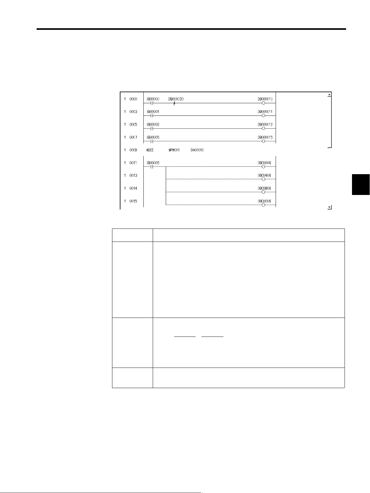
3.4 User Programs
J Example of a Ladder Logic Program for Motion Program Control
The minimum ladder logic program required to control a motion program is shown in the following illustration.
3
The contents of this ladder logic program are shown in the following table.
Step Number Program Content
1to7
8
11 to 15
The signals connected to the MP930 external input signals are stored as the motion
program control signals.
IW0000 (external input signals)
ters)
S Program operation start
S Program pause
S Program stop
S Alarm reset
Calls motion program MP001
MSEE MPM001
12
1. Motion program number
2. MSEE work register address
Resets the alarm (bit 6 of OWxx00) using the alarm reset signal (IB00005), and
clears the alarm for each axis.
DA00000
→ DW00001 (second word of MSEE work regis-
When the external input signals (IB00000 to IB00007) connected to the MP930 are input to
DW00001 (second word of MSEE work registers) as motion program control signals using the
ladder logic program shown above, motion program operations such as run, stop and pause can
be performed by the system motion management functions.
3 -19
Page 79

Basic System Operation
3.4.3 Motion Programming
3
A
EXAMPLE
"
Table 3.7 shows an example of the default external input signals that are allocated by the
MP930 on the Group Definition Screen.
Table 3.7 External Input Signals and Motion Program Control Signals
External Signal
Address
IB00000:
IB00001:
IB00002:
IB00003:
IB00004:
IB00005:
External Signal Name BIT Motion Program Control
Program operation start
Program pause
Program stop
Program debugging mode
Program debugging start
Alarm reset
B0:
B1:
B2:
B3:
B4:
B5:
Program operation start request
Program pause request
Program stop request
Program debugging mode selection
Program debugging start request
Alarm reset request
J Automatic Generation of Ladder Logic Programs for Motion
Program Control
Signal
An automatic generation function for the ladder logic programs used to control motion programs is provided with the MP930. This function enables JOG operations and program operations to be performed without the need for special ladder logic programs to be created, and
greatly reduces the system startup time.
3 -20
Page 80

3.4 User Programs
Input signals
by group
Number of motion programs that can be
started simultaneously by an H drawing
Automatic generation of a ladder logic
program for motion program control
Input signals
by axis
3
INFO
Group 1
H01 H02 H03 H04
Main motion
management
ladder logic
program for
Group 1
H01.01
Manual
H01.02
management
ladder logic
program for
axis 1
H01.03
1
.
.
.
Group 2 Group 3 Group 4
Main motion
management
ladder logic
program for
Group 2
H02.01
Manual
H01.02
management
ladder logic
program for
1
axis 1
H01.03
1
.
.
.
Main motion
management
ladder logic
program for
Group 3
H03.01
Manual
H01.02
management
ladder logic
program for
axis 1
H01.03
1
.
.
Main motion
management
ladder logic
program for
management
.
Group 4
H04.01
Manual
H01.02
ladder logic
program for
1
axis 1
H01.03
1
.
.
.
1. The ladder logic programs that are generated for motion program control are created automatically using the
external input signals that are a llocated on the Group Definition Screen. These ladder logic programs c an
also be used as is.It is recommended, however, that they be used as templates to be optimized (changed) to
suit individual system requirement.
2. When a ladder logic programs used for motion program control is created by automatic generation, up to
four motion programs can be called simultaneously from the ladder logic program. In other words, when
automatic generation is used, a maximum of four groups will be controlled.
3 -21
Page 81

Basic System Operation
F
3.5.1 Standard System Functions
3.5 Functions
This section explains the methods of using and the advantages of the MP930 functions.
Functions are executed by being called from a parent, child, or grandchild drawing using the
FSTART instruction.
Unlike child and grandchild drawings, functions can be called from any drawing. The same function can also be called simultaneously from drawings of different types and different hierarchies.
Moreover, a function can also be called from another function that was previously created.
The following advantages can be obtained by using functions:
D Programs can be easily divided into parts.
3
D Programs can be easily prepared and maintained.
Functions are divided into standard system functions, which are provided by the system, and user
functions, which are defined by the user.
3.5.1 Standard System Functions
Seven functions, including the transfer function, are provided by the system as standard functions. See Table 3.8. The user cannot change the system functions.
Table 3.8 List of Standard System Functions
Type Name Symbol Description
System
unctions
Counter COUNTER Up/down counter
First-in first-out FINFOUT First-in or first-out stack
Trace function TRACE Data trace execution control
Data trace read DTRC-RD Data readout from data trace memory to
Failure trace readout FTRC-RD Data readout from failure trace memory to
user memory
user memory
Inverter trace read ITRC-RD Reads inverter trace data to store it in user
registers
Inverter constant
write
Inverter constant read ICNS-RD Reads inverter constants to registers
Send message function
Receive message
function
ICNS-WR Writes inverter constants
MSG-SND Sending a message from a Communica-
tions Module
MSG-RCV Receiving a message from a Communica-
tions Module
3 -22
Page 82

3.5.2 Creating User Functions
The body of the function (program) and the function definitions can be set by the user. The
maximum number of user functions is 500 per drawing.
For details on the CP-717 operation methods, refer to the MP9jj Machine Controller Pro-
gramming Software User’s Manuals (SIEZ-C887-2.2-1, SIEZ-C887-2.2-2). For details on
instructions, such as the FSTART instruction, refer to the MP9jj Machine Controller Ladder
Programming User’s Manual (SIEZ-C887-1.2). The methods for creating user functions is explained according to the following procedure.
1. Determining I/O Specifications
Determine the number of inputs and outputs and the data types.
2. Defining Function I/O
Input using the CP-717.
3. Programming the Body of the Function
3.5 Functions
3
Prepare in the same way as the drawings, except that different registers are used. Program
according to the correspondence between the register numbers used in the body of the
function program and the I/O data used when calling the function.
4. Preparing the Program that Calls the Function
Input using the following procedure:
a) Use the FSTART instruction to input the function name.
b)Use the FIN instruction to connect the input data.
c) Use the FOUT instruction to connect the output data.
J Determining the I/O Specifications
When a user function is created, the function capabilities, the number of inputs and outputs
required to satisfy the function, and other specifications must first be determined. Determine
the four types of specification shown in Table 3.9.
Table 3.9 Overview of Function Definition Values
Specification to
be Determined
Function Name
Number of Inputs
Up to eight characters can be input.
The number of arguments input into a function. Up to 16 can be input.
Overview
Up to 17 arguments are possible if the address input is also counted.
Number of
Address Inputs*
Number of
Outputs
* Indicates the number of pointers to be provided for the external function registers
used by the function.
The designated number of addresses required by the function. A maximum of
one value can be input.
The number of outputs from the function. Up to 16 can be input.
3 -23
Page 83

Basic System Operation
3.5.2 Creating User Functions
J Defining Function I/O
The function name and other specifications determined in the previous step are defined using
the CP-717. For details on operation methods, refer to the MP9jj Machine Controller Pro-
gramming Software User’s Manuals (SIEZ-C887-2.2-1, SIEZ-C887-2.2-2).
3
A
EXAMPLE
"
The following illustration shows the graphic representation of a function when the following
function is defined: Function name = TEST, number of inputs = 4, number of address inputs
= 1, and number of outputs = 4.
TEST
IN_01
IN_02
IN_03
IN_04
IN_05
OUT_01
OUT_02
OUT_03
OUT_04
Note 1.
After creating the graphic representation of
the function, define the data types of the
functioninputs,outputs, and addressinputs.
2. Three datatypescan be defined:Bit,integer,
and long integer.
3. When thedatatypesare defined, thesystem
automatically allocates inputs to the X registers, outputs to the Y registers, and address
inputs to the A registers.
Figure 3.12 Graphic Representation of a Function 1 (Example)
The following illustration shows an example of the I/O definitions of a function.
Bit numeric input
Bit numeric input
Real number numeric input
Integer numeric input
Figure 3.13 Graphic Representation of a Function 2 (Example)
I/O signal addresses are automatically allocated from the highest signal on the graphic representation. For the example given in Figure 3.13, the allocation of each I/O register will be as
shown in Table 3.10.
===>
===>
TEST
IN_01
BIT1
IN_02
BIT2
IN_03
FLT1
IN_04
INT1 INT2
3 -24
IN_05
ADR
OUT_01
OUT_02
OUT_03
OUT_04
BIT3
BIT4
LNG1
Bit numeric output
Bit numeric output
Long integer numeric output
===>
===>
Integer numeric output
Page 84

Table 3.10 Allocation of I/O Registers
Name Data Type I/O Register
3.5 Functions
IN_01 (BIT1)
IN_02 (BIT2)
IN_03 (FLT1)
IN_04 (INT1)
IN_05 (ADR)
OUT_01 (BIT3)
OUT_02 (BIT4)
OUT_03 (LNG1)
OUT_04 (INT2)
XW00000 and YW00000 of the X and Y registers are used for bit data.
Note
Bit XB000000
Bit XB000001
Real number XF00001
Integer XW00003
Address input AW00000
Bit YB000000
Bit YB000001
Double integer YL00001
Integer YW00003
The function I/O registers shown in Figure 3.13 are allocated automatically. The external
framework of the function is completed at this stage.
J Creating the Body of the Function
3
The body of the function is created in the same way as the drawings except that the types of
register used are different. For details on the registers, see 3.6.3 Types of Register.
J Creating the Program that Calls the Function
The user function is completed when the graphic representation and body program of the function have been created. As with the standard system functions, user functions can be called
from any parent, child, or grandchild drawing or any other user function.
Functions can be called from a drawing or from within the program of another user function
by using the following procedure. For details on the operation methods, refer to the MP9jj
Machine Controller Programming Software User ’s Manuals (SIEZ-C887-2.2-1, SIEZC887-2.2-2) .
1. Input the function name using the FSTART instruction.
Example: Input “FSTART, Enter Key, TEST, Enter Key”.
The previously defined graphic representation of the function will be displayed.
2. Use the FIN instruction to create the input data program.
Provide input data for the function inputs and address inputs.
3. Use the FOUT instruction to create the output data program.
3 -25
Page 85

Basic System Operation
3.5.2 Creating User Functions
Example: I/O data is provided for the graphic representation as shown in the following illustration.
TEST
3
DB000000
DB000001
DF00001
DW00003
===>
===>
BIT1
BIT2
FLT1
INT1 INT2
ADR
MA00300
BIT3
BIT4
LNG1
===>
===>
DB000020
DB000021
DL00010
DW00012
Figure 3.14 Graphic Representation for which Input Data is Provided (Example)
Table 3.11 Relationship Between I/O Data and Internal Function Registers
Name I/O Data Internal Function Register
BIT1 DB000000 XB000000
BIT2 DB000001 XB000001
FLT1 DF00001 XF00001
INT1 DW00003 XW00003
ADR MA00300 AW00000
BIT3 OB00020 YB000000
BIT4 OB00021 YB000001
LNG1 DL00010 YL00001
INT2 DW0012 YW00003
In the table, address input register AW00000 is allocated to MA00300. That is, registers
AW00000, AW00001, and so on, used inside the TEST function correspond to external
registers MA00300, MA00301, and so on. Therefore, if a given value in AW00000 is
stored inside the function, this value will be stored in MA00300.
3 -26
Page 86

3.5 Functions
INFO
Internal function
AW00000
AW00001
AW00002
AW00003
Pointer
External registers
MA00300
MA00301
MA00302
MA00303
Figure 3.15 Pointer Designation for Address Input Registers
4. Creating a motion program that calls the function.
User functions can also be called from motion programs.
Example: The user functions shown in Table 3.11 would be called from a motion program
using the following coding:
UFC TEST DB000000 DB000001 DF00001 DW00003,MA00300,
DB000020 DB000021 DL00010 DW00012;
Conditions for referencing a user function from a motion program:
S The first item of output data must be bit data.
This output will be the completion signal for moving to the next motion command.
UFC DB000000..., MA00300, DB000020...; ↓ condition BB000020==ON
MVS [X]100. [Y]200. F10000;
.
.
.
3
3 -27
Page 87

3
Basic System Operation
3.6.1 Register Designation Methods
3.6 Registers
This section explains the types of register used by MP930 user programs and how these registers
are used.
3.6.1 Register Designation Methods
Registers can be designated by direct designation of the register number or by symbolic designation. These two types of register designation can be used together in the same user program.
When symbolic designation is used, the correspondence between the symbols and the register
numbers is defined in the symbol table that is described later.
Table 3.12 shows the register designation methods.
Table 3.12 Register Designation Methods
Designation Type
Direct Register
Number
Designation
Symbol Designation
Bit registers: MB00100Ax
Integer registers: MW00100x
Double integer registers: ML00100x
Real # registers: MF00100x
Address registers: MA00100x
x: For subscripts, add the subscript i or j after the register number.
Bit registers: RESET-A.x
Integer registers: STIME-H.x
Double integer registers: POS-REF.x
Real # registers: IN-DEF.x
Address registers: PID-DATA.x
Address registers are designated using up to 8 alphanumeric characters.
x: For subscripts, add a period (.) and then the subscript i or j after the symbol.
J Direct Register Number Designation
Description
Register number: V T No. [Bit No.] [Subscript]
When T = B (bit) (hexadecimal, 0 to F)
Register No. for V (decimal or hexadecimal)
Data type of V (T: B | W | L | F | A)
Type of register
Drawing: (V: S | M | I | O | C | # | D)
Function: (V: S | M | I | O | C | # | D | X | Y | Z | A)
3 -28
Can designate the subscript i or j.
Page 88

J Symbol Designation
3.6 Registers
Symbol: [Symbol Name] [Subscript]
3.6.2 Data Types
There are five data types: Bit, integer, double integer, real number, and address. Use them as
required. Address data is used only for pointer designations inside functions. For details, refer
to the MP9jj Ladder Programming Manual (SIEZ-C887-1.2). Table 3.13 shows the data
types.
Table 3.13 Data Types and Numeric Range
Type Data Type Numeric Range Remarks
[.]
Can designate the subscript i or j.
Required if a subscript is to be used
(symbol name and subscript delimiter)
(Name given to the register, 8 characters or less)
X
XXXXXXX
Alphanumeric characters or symbols
Alphabetic character or symbol
(A numeral cannot be designated at the
beginning of a symbol name.)
3
B
W
L
F
A
Bit ON, OFF Used in relay circuits.
Integer −32768 to +32767
(8000H) (7FFFH)
Double integer −2147483648 to +2147483647
(80000000H) (7FFFFFFFH)
Real number
Address 0 to 32767 Used only for pointer designations.
±(1.175E−38 to 3.402E+38), 0
Used in numeric operations.
The values in parentheses ( ) are used in
logic operations.
Used in numeric operations.
The values in parentheses ( ) are used in
logic operations.
Used in numeric operations.
3 -29
Page 89

Basic System Operation
3.6.2 Data Types
D Register Designations and Data Types
[MB001006]
3
FED CBA9876543210
[MW00100]
[MW00101]
[MW00102]
[MW00103]
D Pointer Designations
Memory address
nn
[MA00100]
Register area
.
.
.
[MB00103A]
[MB001003]
[MW00100]
[MW00101]
[MW00102]
[MW00103]
[ML00100]
[MF00100]
[ML00102]
[MF00102]
[ML00100]
[MF00100]
EXAMPLE
A
J Examples of Use by Data Type
Some examples of use by data type are explained below.
Bits
Bits are used for relay circuit ON/OFF or for logic operations.
IB000001
IFON
OB000001 ∨ 1
"
D Motion Program Example
MB000101=IB000100;
IF IB000001==1;
DB000001=DB000001|1
MB000101IB000100
OB000001
3 -30
Page 90

Words
Words are used for numeric operations and logic operations.
3.6 Registers
A
EXAMPLE
MW00100 ∨ H00FF
MW00102 + 12345
MW00104 INV
"
D Motion Program Example
MW00101
MW00103
MW00105
MW00101=MW00100|00FFH;
MW00103=MW00102+12345;
MW00105=MW00104;
3
Double-length Integers
Double-length integers are used for numeric operations and logic operations.
ML00100 + ML00102
ML00106 × ML00108 ÷ 18000
ML00112 BIN
ML00104
MW00110
ML00114
A
EXAMPLE
A
EXAMPLE
"
D Motion Program Example
ML00104=ML00100+ML00102;
ML00110=ML00106∗ML00108/18000;
ML00114=BIN (ML00112);
Real Numbers
Real numbers are used for floating-point numeric operations.
1.23456
DF00102 SIN
(30.0) (0.5)
DF00200 TAN
(45.0) (1.0)
"
D Motion Program Example
DF00100=1.23456;
DF00104=SIN (DF00102);
DF00202=TAN (DF00200);
DF00100
(1.23456)
DF00104
DF00202
3 -31
Page 91

Basic System Operation
3.6.2 Data Types
Addresses
Addresses are used only for pointer designations.
MF00200 to MF00228 are used as the parameter table in the following example
3
MF00200
PID MA00200
Parameter table leading address
MF00200 to MF00204 are used as the parameter table in the following example.
MW00200
LAG MA00200
Parameter table leading address
Error input value
Input value
Input value
⇒ MF00022
PID output value
⇒ MW00022
LAG output value
3 -32
Page 92

3.6.3 Types of Register
Registers include drawing registers and function registers.
J Registers in Drawings
The seven types of register shown in Table 3.14 can be used in all drawings and motion pro-
grams.
Table 3.14 Types of Drawing Register
3.6 Registers
Type Name Designation
Method
S
M
I
O
C
#
System registers SB, SW, SL,
SFnnnnn (SAnnnnn)
Data registers MB, MW, ML,
MFnnnnn
(MAnnnnn)
Input registers IB, IW, IL, IFhhhh
(IAhhhh)
Output registers OB, OW, OL,
Ofhhhh (OAhhhh)
Constantregisters CB, CW, CL,
CFnnnnn (CAnnnnn)
# registers #B, #W, #L,
#Fnnnnn (#Annnnn)
Range Description Charac-
teristic
SW00000 to
SW01023
MW00000 to
MW32767
IW0000 to
IW07FF
OW0000 to
OW07FF
CW00000 to
CW04095
#W00000 to
#W16383
System registers provided by the system. Register
number nnnnn is expressed as a decimal number.
When the system is started, SW00000 to SW00049
are cleared to 0.
Data registers are shared by all drawings. Used as
interfaces between drawings. Register number
nnnnn is expressed as a decimal number.
Registers used for input data.
Register number hhhh is expressed as a hexadecimal
number.
Registers used for output data.
Register number hhhh is expressed as a hexadecimal
number.
Constant registers can be referenced only in the program. Register number nnnnn is expressed as a decimal number.
# registers can be referenced only in the program and
can be used only in the corresponding drawing.
The actual range used is specified by the user on the
CP-717. Register number nnnnn is expressed as a
decimal number.
Common
to all
drawings
Unique to
each
drawing
3
D
Note
D registers DB, DW, DL,
DFnnnnn
(DAnnnnn)
The servo parameter register number (input or output register number) depends on the axis number (axes 1 to
14). Table 3.15 shows the servo parameter register numbers for each axis.
DW00000 to
DW16383
3 -33
D registers are unique to each drawing and can be
used only in the corresponding drawing.
The actual range used is specified by the user on the
CP-717. Register number nnnnn is expressed as a
decimal number.
Page 93

Basic System Operation
3.6.3 Types of Register
Table 3.15 Servo Parameter Register Numbers
Axis Number IW (OW) Address Axis Number IW (OW) Address
3
INFO
1
2
3
4
5
6
7
# registers cannot be used in motion programs.
C000 to C03F
C040 to C07F
C080 to C0BF
C0C0 to C0FF
C100 to C13F
C140 to C17F
C180 to C1BF
10
11
12
13
14
8
9
C1C0 to C1FF
C200 to C23F
C240 to C27F
C280 to C2BF
C2C0 to C2FF
C300 to C33F
C340 to C37F
3 -34
Page 94

J Registers in Functions
The 11 types of register shown in Table 3.16 can be used in functions.
Table 3.16 Types of Function Register
3.6 Registers
Type Name Designation
Method
X
Y
Z
A
Function input
registers
Function output
registers
Internal function
registers
External function
registers
XB, XW, XL,
XFnnnnn
YB, YW, YL,
YFnnnnn
ZB, ZW, ZL,
ZFnnnnn
AB, AW, AL,
AFnnnnn
Range Description Charac-
teristic
XW00000 to
XW00016
YW00000 to
YW00016
ZW0000 to
ZW00063
AW0000 to
AW32767
Input to a function.
Bit input: XB000000 to XB0000F
Integer input: XW00001 to XW00016
Double integer input: XL00001 to XL00015
Register number nnnnn is expressed as a decimal
number.
Output from a function.
Bit input: YB000000 to YB0000F
Integer input: YW00001 to XW00016
Double integer input: YL00001 to YL00015
Register number nnnnn is expressed as a decimal
number.
Internal registers unique to each function. Can be
used in the function for internal processes. Register
number nnnnn is expressed as a decimal number.
External registers that use the address input value as
the base address. For linking with S, M, I, O, #, and
DAnnnnn registers. Register number nnnnn is expressed as a decimal number.
Unique to
each
function
3
# registers #B, #W, #L,
#
D registers DB, DW, DL,
D
#Fnnnnn
(Annnnn)
DFnnnnn
(DAnnnnn)
#W00000 to
#W16383
DW00000 to
DW16383
3 -35
Registers that can only be referenced by a function.
Can be used only by the corresponding function.
The actual range used is specified by the user on the
CP-717. Register number nnnnn is expressed as a
decimal number.
Internal registers unique to each function.
Can be used only by the corresponding function.
The actual range used is specified by the user on the
CP-717. Register number nnnnn is expressed as a
decimal number.
Page 95

Basic System Operation
These
registers
canbereferenced
from
any
drawings
or
function.
Use
3.6.4 Using Subscripts I and J
3
Type Charac-
S
M
I
O
C
Note SA, MA, IA, OA, DA, #A, and CA can also be used inside functions.
Name
Method
System registers SB, SW, SL,
SFnnnnn (SAnnnnn)
Data registers MB, MW, ML,
MFnnnnn
(MAnnnnn)
Input registers IB, IW, IL, IFhhhh
(IAhhhh)
Output registers OB, OW, OL,
Ofhhhh (OAhhhh)
Constantregisters CB, CW, CL,
CFnnnnn (CAnnnnn)
Same as the registers for drawings.
These registers can be referenced from any drawings or function. Use
them carefully when the same function is referenced from drawings
with different priority levels.
DescriptionRangeDesignation
teristic
Common
to all
drawings
3.6.4 Using Subscripts I and J
Two types of register, I and J, are used exclusively for modifying relay numbers and register
numbers. I and J have exactly the same function.
An example of each register data type is explained below.
J Subscripts Attached to Bit Data
When subscript i or j is attached to bit data, the value of I or J is added to the relay number.
For example, if I = 2, MB000000i will be the same as MB000002. If J = 27, MB000000j will
be the same as MB00001B.
2I
MB000000i
Equivalent
MB0000002
J Subscripts Attached to Integer Data
When a subscript is attached to integer data, the value of I or J is added to the relay number.
For example, if I = 3, MW00010i will be the same as MW00013. If J = 30, MW00001j will
be the same as MW00031.
00030
MW00001j
J
Equivalent
3 -36
MW00031
Page 96

3.6 Registers
J Subscripts Attached to Double Integer Data
When a subscript is attached to double integer data, the value of I or J is added to the relay
number. For example, if I = 1, ML00000i will be the same as ML00001. ML00000j when J
= 0, and ML00000j when J = 1 will be as follows:
Higher-place word
MW00001
ML00000J when J = 0: ML00000
MW00002 MW00001
ML00000J when J = 1: ML00001
Lower-place word
MW00000
J Subscripts Attached to Real Number Data
When a subscript is attached to double integer data, the value of I or J is added to the relay
number. For example, if I = 1, MF00000i will be the same as MF00001. MF00000j when J =
0, and MF00000j when J = 1 will be as follows:
Higher-place word
MW00001
MF00000J when J = 0: MF00000
MW00002 MW00001
MF00000J when J = 1: MF00001
Lower-place word
MW00000
J Programming Example Using Subscripts
The programming code shown in Figure 3.16 sets the sum of 100 registers from MW00100
to MW00199 in MW00200 using subscript J.
3
INFO
00000
FOR J = 00000 to 00099 by 00001
MW00200 + MW00100j
FEND
Figure 3.16 Programming Example Using a Subscript
Subscripts I and J cannot be used in motion programs.
MW00200
MW00200
3 -37
Page 97

Basic System Operation
3.6.5 I/O and Registers in Functions
3.6.5 I/O and Registers in Functions
Table 3.17 shows the I/O and registers referenced in functions.
Table 3.17 Correspondence Between I/O and Registers in Functions
3
Function I/O
Bit inputs The bit numbers increase continuously from XB000000 in order of the bit
inputs: XB000000, XB000001, XB000002, ……, XB00000F
Integer, double integer,
and real number inputs
Address inputs The address input values correspond to register numbers 0 of the external
Bit outputs The bit number increases consecutively from YB000000 in order of bit out-
Integer, double integer,
and real number outputs
The register numbers increase continuously from XW, XL, and XF00001 in
order of the integer, double integer, and real number inputs:
XW00001, XW00002, XW00003,……, XW00016
XL00001, XL00003, XL00005,
XF00001, XF00003, XF00005, ……, XF00015
register:
Input value = MA00100: MW00100 = AW00000, MW00100 = AW00001...
puts: (YB000000, YB000001, YB000002, YB00000F)
The register numbers increase continuously from YW, YL, and YF00001 in
order of the integer, double integer, and real number outputs.
YW00001, YW00002, YW00003, ......, YW00016
YL00001, YL00003, YL00005, ......, YL00015
YF00001, YF00003, FY00005, ......, YF00015
Function Register
, XL00015
……
3 -38
Page 98

3.6.6 Register Ranges in Programs
Figure 3.17 shows the ranges that can be called for registers in programs.
DWG H03 (Drawing)
3.6 Registers
Registers common to all drawings
Program
500 steps max.
B
Registers for individual drawings
Constant data. 16,384 words max.
(#B, #W, #L, #Fnnnnn)
Individual data. 16,384 words max.
(DB, DW, DL, DFnnnnn)
FUNC-0000 (Function)
Program
500 steps max.
C
Registers for individual functions
Function Input registers 17 words
(XB, XW, YL, YFnnnnn)
Function output registers 17 words
(YB, YW, YL, YFnnnnn)
Internal function registers 64 words
(ZB, ZW, ZL, ZFnnnnn)
Constant data. 16,384 words max.
(#B, #W, #L, #Fnnnnn)
Individual data. 16,384 words max.
(DB, DW, DL, DFnnnnn)
A
D
External function
registers
(AB, AW, AL,
AFnnnnn)
A
System registers
(SB, SW, SL, SFnnnnn)
Data registers
(MB, MW, ML, MFnnnnn)
Input registers
(IB, IW, IL, IFnnnnn)
Output registers
(OB, OW, OL, OFnnnnn)
Constant registers
(CB, CW, CL, CFnnnnn)
3
A: Registers that are common to all drawings can be referenced from any drawing or function.
B: Registers that are unique to each drawing can be referenced only from within that drawing.
C: Registers that are unique to each function can be referenced only from within that function.
D: Registers that are common to all drawings and registers that are unique to each drawing can be
referenced from a function using the external function registers.
Figure 3.17 Referencing Ranges for Registers in Programs
3 -39
Page 99

Basic System Operation
3.7.1 Symbols in Drawings
3.7 Managing Symbols
This section describes symbol management and upward linking, together with the automatic allocation of register numbers.
3.7.1 Symbols in Drawings
The symbols used in drawings are all managed with a symbol table, such as the one shown in
Table 3.18. For details, refer to the MP9jj Ladder programming manual (SIEZ-C887-1.2).
Table 3.18 Drawing Symbol Table (Example)
3
No.
* If a program is written using data configurations such as arrays or indexed data, de-
Register No. Symbol Size * Remarks
0 IB00000 STARTPBL 1 The register number is expressed as a hexade-
cimal number.
1 OB00000 STARTCOM 1 The register number is expressed as a hexade-
cimal number.
2 MW00000 SPDMAS 1
3 MB000010 WORK-DB 16
4 MW00010 PIDDATA 10
5 MW00020 LAUIN 1
6 MW00021 LAUOUT 1
:
N
fine the size to be used in the data configuration. For example, if the data is referenced as PIDDATA_1 and i varies in a range of 0 to 9, define the size as 10.
3 -40
Page 100

3.7.2 Symbols in Functions
All symbols used in the functions are managed with the function symbol table shown in Table
3.19. For the method of defining the function symbol table, refer to the MP9jj Ladder programming manual (SIEZ-C887-1.2) .
Table 3.19 Function Symbol Table
No. Register No. Symbol Size * Remarks
0 XB000000 1
1 XW00001 1
2 AW00001 1
3 AB00000F 1
4 YB000000 1
5 YW00001 1
3.7 Managing Symbols
3
6 ZB000000 4
7 ZW00001 1
8 ZW00002 1
:
N
* If a program is prepared using data configurations such as arrays or indexed data,
define the size to be used in the data configuration. For example, if the data is referenced as PIDDATA_1 and i varies in a range of 0 to 9, define the size as 10.
3 -41
 Loading...