

Page 1
Machine Controller MP920
Motion Module
USER'S MANUAL
YASKAWA
YASKAWA
MANUAL NO. SIEZ-C887-2.5C
Page 2

Copyright © 1999 YASKAWA ELECTRIC CORPORATION
All rights reserved. No part of this publication may be reproduced, stored in a retrieval system,
or transmitted, in any form, or by any means, mechanical, electronic, photocopying, recording,
or otherwise, without the prior written permission of Yaskawa. No patent liability is assumed
with respect to the use of the information contained herein. Moreover, because Yaskawa is constantly striving to improve its high-quality products, the information contained in this manual is
subject to change without notice. Every precaution has been taken in the preparation of this
manual. Nevertheless, Yaskawa assumes no responsibility for errors or omissions. Neither is
any liability assumed for damages resulting from the use of the information contained in this
publication.
Page 3

Using this Manual
Please read this manual to ensure correct usage of the MP920 system. Keep this manual in a
safe place for future reference.
Overview
This manual describes the Motion Modules designed for MP920 Machine Controller.
The following Motion Modules can be used with MP920 Machine Controller.
• SVA-01A 4-axis Servo Module
• SVA-02A 2-axis Servo Module
• SVB-01 MECHATROLINK Interface Servo Module
• PO-01 Pulse Output Module
This manual describes the following items required to use these Motion Modules.
• Motion Module setup
• Installation and connection methods
• Parameters
• Troubleshooting
Read this manual carefully to ensure that motion control is correctly performed using the
MP920 Machine Controller. Also, keep this manual in a safe place so that it can be referred
to whenever necessary.
Intended Audience
This manual is intended for the following users.
• Those responsible for estimating the MP920 system
• Those responsible for deciding whether to apply the MP920 system
• Those responsible for designing the MP920 system so that it can be mounted in the con-
trol and operating panels
• Those responsible for making, inspecting, testing, adjusting, and maintaining the control
and operating panels in which the MP920 is mounted
Basic Terms
Unless otherwise specified, the following definitions are used:
• MP920 = MP920 Machine Controller
• PC: Programmable Logic Controller
• MPE720: The Programming Device Software or a Programming Device (i.e., a personal
computer) running the Programming Device Software
• PLC = Programmable Logic Controller
• “⎯” in “MOV [axis1]⎯...” represents numeric data for axis 1.
iii
Page 4

EXAMPLE
TERMS
Visual Aids
The following aids are used to indicate types of information for easier reference.
IMPORTANT
INFO
Indicates important information that should be memorized.
Indicates supplemental information.
Indicates application examples.
Describes technical terms that are difficult to understand, or in the text
without an explanation being given.
Indication of Reverse Signals
In this manual, the names of reverse signals (ones that are valid when low) are written with a
forward slash (/) before the signal name, as shown in the following example:
• S-ON = /S-ON
• P-CON = /P-CON
iv
Page 5

Related Manuals
Refer to the following related manuals as required.
Thoroughly check the specifications, restrictions, and other conditions of the product before
attempting to use it.
Manual Name Manual Number Contents
Machine Controller MP920 User’s
Manual: Design and Maintenance
Machine Controller MP920
Communications Module User’s Manual
Machine Controller MP900/MP2000
Series Ladder Logic Programming
User’s Manual
Machine Controller MP900/MP2000
Series Motion Programming
User’s Manual
Machine Controller MP900/MP2000
Series User’s Manual
MPE720 Software for Programming
Device
SIEZ-C887-2.1 Describes the design and maintenance for
the MP920 Machine Controller.
SIEZ-C887-2.6 Describes the functions, specifications, and
usage of the MP920 Communications Modules (215IF, 217IF, and 218IF).
SIEZ-C887-1.2 Describes the instructions used in MP900/
MP2000 Series ladder logic programming.
SIEZ-C887-1.3 Describes the motion programming language
used for MP900/MP2000 Series Machine
Controllers.
SIEPC88070005 Describes how to install and operate the
MP900/MP2000 Series programming system MPE720.
v
Page 6
MANDATORY
Safety Information
The following conventions are used to indicate precautions in this manual. Failure to heed
provided in this manual can result in serious or possibly even fatal injury or damage to he
products or to related equipment and systems.
WARNING
CAUTION
Indicates precautions that, if not heeded, could possibly result in loss of
life, serious injury.
Indicates precautions that, if not heeded, could result in relatively serious
or minor injury, damage to the product, or faulty operation.
In some situations, the precautions indicated could have serious consequences if not heeded.
Indicates prohibited actions that must not be performed. For
PROHIBITED
example, this symbol would be used as follows to indicate that fire is
prohibited: .
Indicates compulsory actions that must be performed. For example,
this symbol would be used as follows to indicate that grounding is
compulsory: .
The warning symbols for ISO and JIS standards are different, as shown below.
ISO JIS
The ISO symbol is used in this manual.
Both of these symbols appear on warning labels on Yaskawa products. Please abide by these
warning labels regardless of which symbol is used.
vi
Page 7
Safety Precautions
CAUTION
This section describes precautions to ensure the correct application of the product. Before
installing, operating, maintaining, or inspecting the product, always read this manual and all
other documents provided to ensure correct work procedures and application. Before using
the equipment, familiarize yourself with equipment details, safety information, and all other
precautions.
Handling
• Do not subject the product to halogen gases, such as fluorine, chlovine, bromine, and
iodine, at any time even during transportation or installation.
Failure to observe this caution may cause damage or failure of the product.
Installation
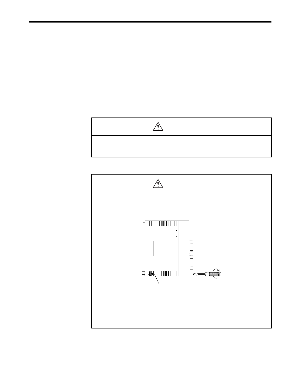
CAUTION
• Firmly tighten the Module mounting screws and terminal block mounting screws to pre-
vent them from loosening during operation.
Loose screws may result in a malfunction of the MP920.
Module mounting screw
(Use an M4 Phillips screw driver.)
• Always turn OFF the power supply to the Module before installing it.
• Insert the connectors of the cables that are to be connected to the MP920 Modules and
secure them well.
Incorrect insertion of the connectors may result in a malfunction of the MP920.
vii
Page 8
MANDATORY
r
Wiring
CAUTION
• Always connect a power supply that meets the given specifications.
Connecting an inappropriate power supply may cause fires.
• Wiring must be performed by qualified personnel.
Incorrect wiring may cause fires, product failure, or electrical shocks.
• Do not accidentally leave foreign matter such as wire chips on the Mounting Base or in
the Module when wiring.
This may cause fires, failures, and malfunctions.
• Always ground the FG terminal to a ground resistance 100Ω or less.
Failure to ground the MP920 may result in electrical shocks or malfunctioning.
Select, separate, and lay external cables correctly.
• Consider the following items when selecting the I/O signal lines (external cables) to
connect the MP920 Module to external devices.
• Mechanical strength
• Noise interference
• Wiring distance
• Signal voltage, etc.
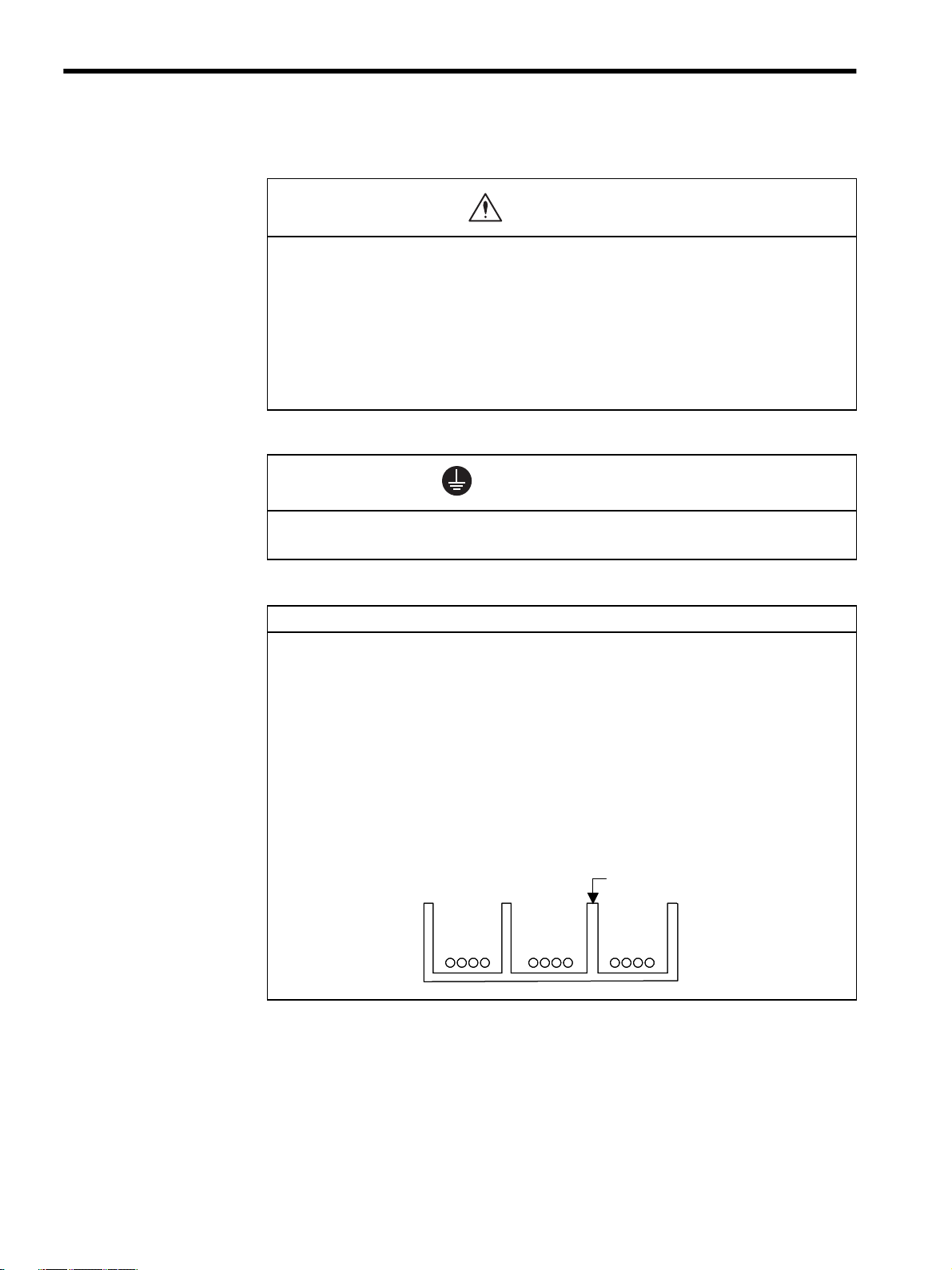
• Separate the I/O signal lines from the power lines both inside and outside the control
panel to reduce the influence of noise from the power lines.
If the I/O signal lines and power lines are not separated properly, malfunctioning may result.
Example of Separated External Cables
Steel separato
Power
circuit
cables
General
control circuit cables
Digital I/O
signal
cables
viii
Page 9
Application
WARNING
PROHIBITED
• Do not touch any Module terminals when the system power is ON.
There is a risk of electrical shock.
• Do not attempt to modify the MP920 programs, force outputs, switch between RUN and
STOP, or perform other similar operations while the MP920 is operating without know-
ing the direct and indirect consequences of the operation.
Incorrect programming or operation may damage the equipment or cause an accident.
Maintenance
• Make sure that the polarity of the Module’s built-in battery is correct. The battery must
be installed correctly and must not be charged, disassembled, heated, thrown into fire,
or short-circuited.
Improper handling may cause the battery to explode or ignite.
WARNING
CAUTION
• Do not attempt to disassemble or modify the MP920 Modules in any way.
Doing so can cause fires, product failure, or malfunctions.
• The customer must not replace any built-in fuses.
If the customer replaces a built-in fuse, the MP920 Module may malfunction or break down.
The built-in fuse must always be replaced by Yaskawa service staff.
ix
Page 10

General
Always note the following to ensure safe use.
• MP920 was not designed or manufactured for use in devices or systems directly related
to human life. Users who intend to use the product described in this manual for special
purposes such as devices or systems relating to transportation, medical, space avia-
tion, atomic power control, or underwater use must contact Yaskawa Electric Corpora-
tion beforehand.
• MP920 has been manufactured under strict quality control guidelines. However, if this
product is to be installed in any location in which a failure of MP920 involves a life and
death situation or in a facility where failure may cause a serious accident, safety
devices MUST be installed to minimize the likelihood of any accident.
• Drawings in this manual show typical product examples that may differ somewhat from
the product delivered.
• This manual may change without prior notice due to product improvements and specifi-
cation changes or for easier use. We will update the manual number of the manual and
issue revisions when changes are made. The revision number of the revised manual
appears on the back of the manual.
• Contact your nearest Yaskawa sales representative or the dealer from whom you pur-
chased the product and quote the manual number on the front page of the manual if
you need to replace a manual that was lost or destroyed.
• Contact your nearest Yaskawa sales representative or the dealer from whom you pur-
chased the product to order new nameplates whenever a nameplate becomes worn or
damaged.
• Products modified by the customer are not covered by the Yaskawa warranty, nor does
Yaskawa assume any liability for injury or damage that may result from such modifica-
tions.
x
Page 11

CONTENTS
Using this Manual- - - - - - - - - - - - - - - - - - - - - - - - - - - - - - - - - - - - - - - iii
Safety Information - - - - - - - - - - - - - - - - - - - - - - - - - - - - - - - - - - - - - - vi
Safety Precautions - - - - - - - - - - - - - - - - - - - - - - - - - - - - - - - - - - - - - vii
1 Overview of Motion Modules
1.1 Module Overview and Features - - - - - - - - - - - - - - - - - - - - - 1-2
1.1.1 Motion Modules - - - - - - - - - - - - - - - - - - - - - - - - - - - - - - - - - - - - - - -1-2
1.1.2 SVA-01A Module - - - - - - - - - - - - - - - - - - - - - - - - - - - - - - - - - - - - - -1-3
1.1.3 SVA-02A Module - - - - - - - - - - - - - - - - - - - - - - - - - - - - - - - - - - - - - -1-4
1.1.4 SVB-01 Module - - - - - - - - - - - - - - - - - - - - - - - - - - - - - - - - - - - - - - -1-6
1.1.5 PO-01 Module - - - - - - - - - - - - - - - - - - - - - - - - - - - - - - - - - - - - - - - -1-8
1.2 System Configuration - - - - - - - - - - - - - - - - - - - - - - - - - - - - 1-9
1.2.1 System Configuration Examples - - - - - - - - - - - - - - - - - - - - - - - - - - -1-9
1.3 Specifications- - - - - - - - - - - - - - - - - - - - - - - - - - - - - - - - - 1-10
1.3.1 General Specifications - - - - - - - - - - - - - - - - - - - - - - - - - - - - - - - - -1-10
1.3.2 Function Lists- - - - - - - - - - - - - - - - - - - - - - - - - - - - - - - - - - - - - - - - 1-11
2 Motion Control
2.1 Overview of Motion Control - - - - - - - - - - - - - - - - - - - - - - - - 2-2
2.1.1 Motion Control for the MP920 - - - - - - - - - - - - - - - - - - - - - - - - - - - - -2-2
2.1.2 Motion Control Methods - - - - - - - - - - - - - - - - - - - - - - - - - - - - - - - - -2-4
2.1.3 Examples of Motion Control Applications - - - - - - - - - - - - - - - - - - - - -2-5
2.2 Control Modes - - - - - - - - - - - - - - - - - - - - - - - - - - - - - - - - - 2-7
2.2.1 Overview of Control Modes - - - - - - - - - - - - - - - - - - - - - - - - - - - - - - -2-7
2.2.2 Speed Reference Output Mode - - - - - - - - - - - - - - - - - - - - - - - - - - - -2-8
2.2.3 Torque Reference Output Mode - - - - - - - - - - - - - - - - - - - - - - - - - - -2-12
2.2.4 Phase Control Mode - - - - - - - - - - - - - - - - - - - - - - - - - - - - - - - - - - -2-15
2.2.5 Zero Point Return Mode - - - - - - - - - - - - - - - - - - - - - - - - - - - - - - - -2-22
2.3 Position Control - - - - - - - - - - - - - - - - - - - - - - - - - - - - - - - 2-26
2.3.1 Prerequisites for Position Control - - - - - - - - - - - - - - - - - - - - - - - - - -2-26
2.3.2 Position Control Without Using Motion Commands - - - - - - - - - - - - -2-41
2.4 Position Control Using Motion Commands - - - - - - - - - - - - 2-45
2.4.1 Overview of Motion Commands - - - - - - - - - - - - - - - - - - - - - - - - - - -2-45
2.4.2 Positioning (POSING) - - - - - - - - - - - - - - - - - - - - - - - - - - - - - - - - - -2-48
2.4.3 External Positioning (EX_POSING) - - - - - - - - - - - - - - - - - - - - - - - -2-51
2.4.4 Zero Point Return (ZRET) - - - - - - - - - - - - - - - - - - - - - - - - - - - - - - -2-55
2.4.5 Interpolation (INTERPOLATE, END_OF_INTERPOLATE) - - - - - - - -2-70
2.4.6 Interpolation with Position Detection (LATCH) - - - - - - - - - - - - - - - - -2-73
2.4.7 Fixed Speed Feed (FEED)- - - - - - - - - - - - - - - - - - - - - - - - - - - - - - -2-74
2.4.8 Fixed Length Feed (STEP) - - - - - - - - - - - - - - - - - - - - - - - - - - - - - -2-77
2.4.9 Zero Point Setting (ZSET) - - - - - - - - - - - - - - - - - - - - - - - - - - - - - - -2-81
xi
Page 12

3 Motion Module Allocations and Setup
3.1 Allocations and Configuration Definitions - - - - - - - - - - - - - - 3-2
3.1.1 Motion Module Allocation Method - - - - - - - - - - - - - - - - - - - - - - - - - - 3-2
3.1.2 Setting Module Definitions - - - - - - - - - - - - - - - - - - - - - - - - - - - - - - - 3-4
3.1.3 Saving Module Definitions - - - - - - - - - - - - - - - - - - - - - - - - - - - - - - - 3-6
3.2 Individual Module Definitions - - - - - - - - - - - - - - - - - - - - - - - 3-7
3.2.1 MECHATROLINK Definitions - - - - - - - - - - - - - - - - - - - - - - - - - - - - - 3-7
3.2.2 Setting Motion Parameters - - - - - - - - - - - - - - - - - - - - - - - - - - - - - - 3-10
4 Parameters
4.1 Overview of Parameters - - - - - - - - - - - - - - - - - - - - - - - - - - 4-2
4.1.1 Parameter Classifications - - - - - - - - - - - - - - - - - - - - - - - - - - - - - - - - 4-2
4.1.2 Modules and Motion Parameter Registers - - - - - - - - - - - - - - - - - - - - 4-3
4.2 Parameter List by Module - - - - - - - - - - - - - - - - - - - - - - - - - 4-5
4.2.1 Motion Fixed Parameters - - - - - - - - - - - - - - - - - - - - - - - - - - - - - - - - 4-5
4.2.2 Motion Setting Parameters - - - - - - - - - - - - - - - - - - - - - - - - - - - - - - 4-10
4.2.3 Motion Monitoring Parameters - - - - - - - - - - - - - - - - - - - - - - - - - - - 4-18
5 SVA Module Specifications and Handling
5.1 SVA-01A Module - - - - - - - - - - - - - - - - - - - - - - - - - - - - - - - 5-2
5.1.1 Hardware Specifications - - - - - - - - - - - - - - - - - - - - - - - - - - - - - - - - - 5-2
5.1.2 Handling - - - - - - - - - - - - - - - - - - - - - - - - - - - - - - - - - - - - - - - - - - - - 5-3
5.2 SVA-02A Module - - - - - - - - - - - - - - - - - - - - - - - - - - - - - - 5-24
5.2.1 Hardware Specifications - - - - - - - - - - - - - - - - - - - - - - - - - - - - - - - - 5-24
5.2.2 Handling - - - - - - - - - - - - - - - - - - - - - - - - - - - - - - - - - - - - - - - - - - - 5-25
5.3 Differences between SVA-01A and SVA-02A Modules - - - - 5-43
5.3.1 Differences in Hardware - - - - - - - - - - - - - - - - - - - - - - - - - - - - - - - - 5-43
5.3.2 Differences in Servo Connectors - - - - - - - - - - - - - - - - - - - - - - - - - - 5-44
5.3.3 Differences in External I/O Signals - - - - - - - - - - - - - - - - - - - - - - - - 5-46
5.3.4 Precautions on Connecting the SVA-02A Module - - - - - - - - - - - - - - 5-47
5.3.5 Connection with SGDA-S SERVOPACK - - - - - - - - - - - - - - - - 5-48
5.4 SVA-01A and SVA-02A Parameters - - - - - - - - - - - - - - - - - 5-52
5.4.1 Motion Fixed Parameters - - - - - - - - - - - - - - - - - - - - - - - - - - - - - - - 5-52
5.4.2 Motion Setting Parameters - - - - - - - - - - - - - - - - - - - - - - - - - - - - - - 5-62
5.4.3 Motion Monitoring Parameters - - - - - - - - - - - - - - - - - - - - - - - - - - - 5-83
6 SVB Module Specifications and Handling
6.1 SVB-01 Module - - - - - - - - - - - - - - - - - - - - - - - - - - - - - - - - 6-2
6.1.1 Hardware Specifications - - - - - - - - - - - - - - - - - - - - - - - - - - - - - - - - - 6-2
6.1.2 Handling - - - - - - - - - - - - - - - - - - - - - - - - - - - - - - - - - - - - - - - - - - - - 6-3
xii
Page 13

6.2 SVB-01 Parameters - - - - - - - - - - - - - - - - - - - - - - - - - - - - 6-16
6.2.1 Motion Fixed Parameters - - - - - - - - - - - - - - - - - - - - - - - - - - - - - - -6-16
6.2.2 Motion Setting Parameters - - - - - - - - - - - - - - - - - - - - - - - - - - - - - -6-23
6.2.3 Motion Monitoring Parameters - - - - - - - - - - - - - - - - - - - - - - - - - - - -6-38
6.2.4 Σ Series SERVOPACK parameters - - - - - - - - - - - - - - - - - - - - - - - -6-45
6.2.5 Σ-II Series SERVOPACK Parameters - - - - - - - - - - - - - - - - - - - - - - -6-52
6.2.6 Relationship of SERVOPACK Parameters to SVB-01 Parameters - - - 6-64
7 PO-01 Module Specification and Handling
7.1 PO-01 Module - - - - - - - - - - - - - - - - - - - - - - - - - - - - - - - - - 7-2
7.1.1 Hardware Specifications - - - - - - - - - - - - - - - - - - - - - - - - - - - - - - - - -7-2
7.1.2 Handling - - - - - - - - - - - - - - - - - - - - - - - - - - - - - - - - - - - - - - - - - - - -7-3
7.2 Functions- - - - - - - - - - - - - - - - - - - - - - - - - - - - - - - - - - - - 7-16
7.2.1 Motion Control Functions- - - - - - - - - - - - - - - - - - - - - - - - - - - - - - - -7-16
7.2.2 Motion Functions - - - - - - - - - - - - - - - - - - - - - - - - - - - - - - - - - - - - -7-19
7.2.3 Program Example- - - - - - - - - - - - - - - - - - - - - - - - - - - - - - - - - - - - -7-22
7.2.4 Out-of-step Detection - - - - - - - - - - - - - - - - - - - - - - - - - - - - - - - - - -7-25
7.2.5 Emergency Stop- - - - - - - - - - - - - - - - - - - - - - - - - - - - - - - - - - - - - -7-29
7.3 PO-01 Parameters - - - - - - - - - - - - - - - - - - - - - - - - - - - - - 7-31
7.3.1 Motion Fixed Parameters - - - - - - - - - - - - - - - - - - - - - - - - - - - - - - -7-31
7.3.2 Motion Setting Parameters - - - - - - - - - - - - - - - - - - - - - - - - - - - - - -7-39
7.3.3 Motion Monitoring Parameters - - - - - - - - - - - - - - - - - - - - - - - - - - - -7-49
8 Troubleshooting
8.1 Overview of Alarms - - - - - - - - - - - - - - - - - - - - - - - - - - - - - 8-2
8.1.1 Description of Motion Alarms - - - - - - - - - - - - - - - - - - - - - - - - - - - - - -8-2
8.1.2 Processing Flow for Motion Alarms - - - - - - - - - - - - - - - - - - - - - - - - -8-5
8.2 Alarms and Actions Taken - - - - - - - - - - - - - - - - - - - - - - - - - 8-6
8.2.1 Alarm IL22 - - - - - - - - - - - - - - - - - - - - - - - - - - - - - - - - - - - - - - - -8-6
8.2.2 Motion Alarm Configuration - - - - - - - - - - - - - - - - - - - - - - - - - - - - - -8-20
8.2.3 Motion Module Error Displays and Actions Taken - - - - - - - - - - - - - -8-22
9 Application Precautions
9.1 Vertical Axis Control - - - - - - - - - - - - - - - - - - - - - - - - - - - - - 9-2
9.1.1 Overview - - - - - - - - - - - - - - - - - - - - - - - - - - - - - - - - - - - - - - - - - - - -9-2
9.1.2 SGDA SERVOPACK Connections - - - - - - - - - - - - - - - - - - - - - - - - - -9-3
9.1.3 SGDB SERVOPACK Connections - - - - - - - - - - - - - - - - - - - - - - - - - -9-5
9.1.4 SGDM/SGDS SERVOPACK Connections - - - - - - - - - - - - - - - - - - - - -9-8
9.2 Overtravel Function - - - - - - - - - - - - - - - - - - - - - - - - - - - - 9-10
9.2.1 Overview - - - - - - - - - - - - - - - - - - - - - - - - - - - - - - - - - - - - - - - - - - - 9-10
9.2.2 Overtravel Input Signal Connections- - - - - - - - - - - - - - - - - - - - - - - -9-10
9.2.3 Parameter Settings - - - - - - - - - - - - - - - - - - - - - - - - - - - - - - - - - - - -9-12
xiii
Page 14

9.3 Software Limit Function - - - - - - - - - - - - - - - - - - - - - - - - - 9-16
9.3.1 Overview- - - - - - - - - - - - - - - - - - - - - - - - - - - - - - - - - - - - - - - - - - - 9-16
9.3.2 Fixed Parameter Settings - - - - - - - - - - - - - - - - - - - - - - - - - - - - - - - 9-16
9.3.3 Processing after an Alarm- - - - - - - - - - - - - - - - - - - - - - - - - - - - - - - 9-17
9.4 Reverse Rotation Mode - - - - - - - - - - - - - - - - - - - - - - - - - 9-18
9.4.1 Overview- - - - - - - - - - - - - - - - - - - - - - - - - - - - - - - - - - - - - - - - - - - 9-18
9.4.2 Absolute Encoder Setting - - - - - - - - - - - - - - - - - - - - - - - - - - - - - - - 9-20
9.4.3 Incremental Encoder Setting- - - - - - - - - - - - - - - - - - - - - - - - - - - - - 9-21
10 CNTR-01 Module Specifications and Handling
10.1 CNTR-01 Module - - - - - - - - - - - - - - - - - - - - - - - - - - - - - 10-2
10.1.1 Hardware Specifications - - - - - - - - - - - - - - - - - - - - - - - - - - - - - - - 10-2
10.1.2 Handling - - - - - - - - - - - - - - - - - - - - - - - - - - - - - - - - - - - - - - - - - - 10-3
10.2 Using the CNTR-01 Module- - - - - - - - - - - - - - - - - - - - - 10-11
10.2.1 Overview- - - - - - - - - - - - - - - - - - - - - - - - - - - - - - - - - - - - - - - - - 10-11
10.2.2 Fixed Parameters- - - - - - - - - - - - - - - - - - - - - - - - - - - - - - - - - - - 10-13
10.2.3 Setting I/O Data - - - - - - - - - - - - - - - - - - - - - - - - - - - - - - - - - - - - 10-15
10.3 Counter Modes - - - - - - - - - - - - - - - - - - - - - - - - - - - - - 10-22
10.3.1 Reversible Counter Mode - - - - - - - - - - - - - - - - - - - - - - - - - - - - - 10-22
10.3.2 Interval Counter Mode - - - - - - - - - - - - - - - - - - - - - - - - - - - - - - - 10-24
10.3.3 Frequency Measurement - - - - - - - - - - - - - - - - - - - - - - - - - - - - - 10-26
10.4 CNTR-01 Module I/O Circuits - - - - - - - - - - - - - - - - - - - 10-30
10.4.1 Pulse Input Specifications - - - - - - - - - - - - - - - - - - - - - - - - - - - - - 10-30
10.4.2 Latch Input Circuits - - - - - - - - - - - - - - - - - - - - - - - - - - - - - - - - - 10-32
10.4.3 Coincidence Output Circuits - - - - - - - - - - - - - - - - - - - - - - - - - - - 10-33
10.5 CNTR-01 Counter Module Connections - - - - - - - - - - - - 10-34
10.5.1 Connections to Pulse Generators - - - - - - - - - - - - - - - - - - - - - - - 10-34
10.5.2 Pulse C Signals - - - - - - - - - - - - - - - - - - - - - - - - - - - - - - - - - - - - 10-36
Appendix A Module Appearance
A.1 Motion Modules - - - - - - - - - - - - - - - - - - - - - - - - - - - - - - - - A-2
A.2 Counter Module - - - - - - - - - - - - - - - - - - - - - - - - - - - - - - - - A-5
INDEX
Revision History
xiv
Page 15

1
Overview of Motion Modules
This chapter provides an overview of the Motion Modules and describes their
features.
1.1 Module Overview and Features - - - - - - - - - - - - - - - - - - - - - 1-2
1.1.1 Motion Modules - - - - - - - - - - - - - - - - - - - - - - - - - - - - - - - - - - - - - - 1-2
1.1.2 SVA-01A Module - - - - - - - - - - - - - - - - - - - - - - - - - - - - - - - - - - - - - 1-3
1.1.3 SVA-02A Module - - - - - - - - - - - - - - - - - - - - - - - - - - - - - - - - - - - - - 1-4
1.1.4 SVB-01 Module - - - - - - - - - - - - - - - - - - - - - - - - - - - - - - - - - - - - - - 1-6
1.1.5 PO-01 Module - - - - - - - - - - - - - - - - - - - - - - - - - - - - - - - - - - - - - - - 1-8
1.2 System Configuration - - - - - - - - - - - - - - - - - - - - - - - - - - - -1-9
1.2.1 System Configuration Examples - - - - - - - - - - - - - - - - - - - - - - - - - - - 1-9
1
1.3 Specifications - - - - - - - - - - - - - - - - - - - - - - - - - - - - - - - - - 1-10
1.3.1 General Specifications - - - - - - - - - - - - - - - - - - - - - - - - - - - - - - - - - 1-10
1.3.2 Function Lists - - - - - - - - - - - - - - - - - - - - - - - - - - - - - - - - - - - - - - - 1-11
1-1
Page 16
1 Overview of Motion Modules
1.1.1 Motion Modules
1.1 Module Overview and Features
This section provides an overview of the Motion Modules and describes their features.
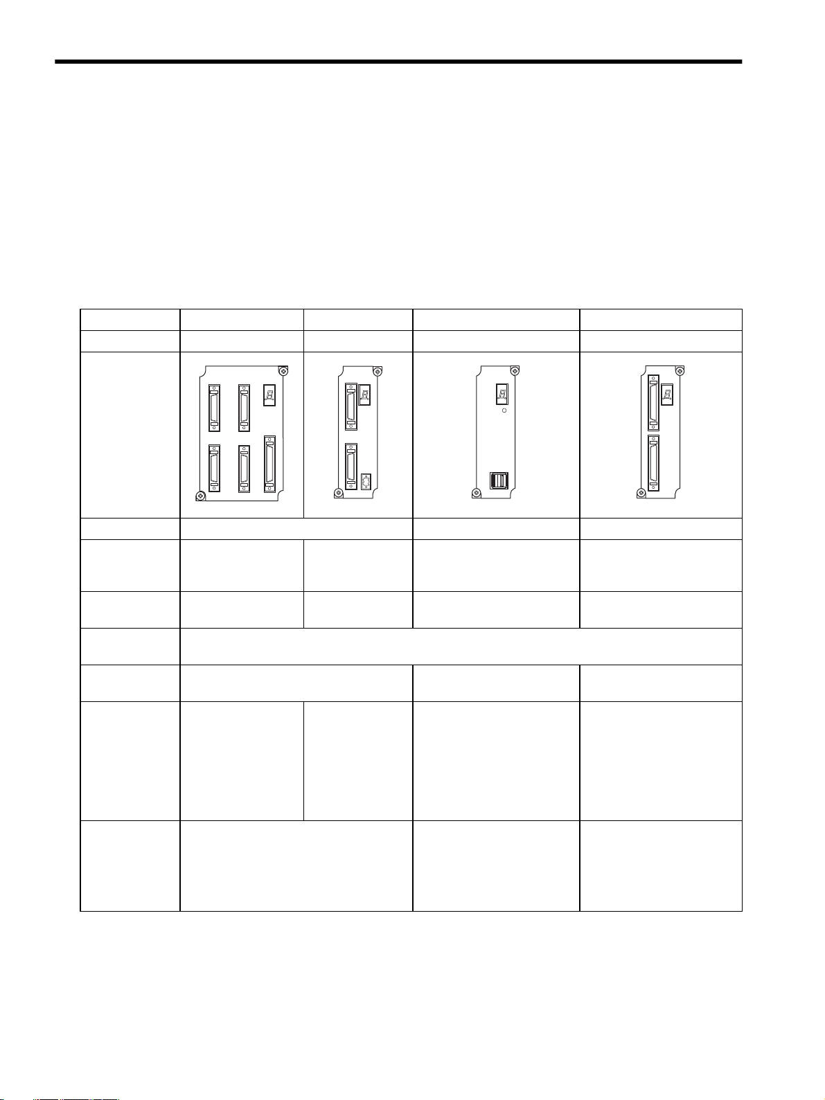
1.1.1 Motion Modules
The following table lists the Motion Modules that can be used with the MP920.
Description SVA-01A SVA-02A SVB-01 PO-01
Model Number JEPMC-MC200A JEPMC-MC220A JEPMC-MC210 JEPMC-PL210
Appearance
SVA-01
CN3
CN1
CN2
STATUS
CN5
CN4
SVA-02
CN1
STATUS
CN2
SVB-01
STATU S
TRX
PO-01
CN1
STATUS
CN2
Interface
Number of Controlled Axes per
Module
Maximum Number of Modules
Total Number of
Modules
Pulse Counting
Methods
Control
Functions
Motion
Functions
CN3
+24V
0V
CN1
Analog MECHATROLINK Pulse
4 2 14 4
15 16 16 16
16 max.
A/B, Up/Down, sign, ×1/2/4 ×4 −
• Speed reference
output
• Synchronized phase
control
• Position control
• Speed reference
output
• Synchronized
phase control
• Position control
• Position control only
Position loop is performed
by Servo Drivers. The SVB01 Module outputs position
reference values.
• Torque reference output
• Positioning
• Linear interpolation
• Circular interpolation
• Helical interpolation
• External positioning
• Positioning
• Linear interpolation
• Circular interpolation
• Helical interpolation
• External positioning
• Position control only
Open loop control
The PO-01 Module outputs
reference pulses.
• Positioning
• Linear interpolation
• Circular interpolation
• Helical interpolation
1-2
Page 17
1.1 Module Overview and Features
Description SVA-01A SVA-02A SVB-01 PO-01
Model Number JEPMC-MC200A JEPMC-MC220A JEPMC-MC210 JEPMC-PL210
Applicable Servo Drivers and
Inverters
• Servo Drivers
SGDA-S
SGDB-
SGDM-
SGDS-
• Inverters
• Servo Drivers
SGD-N
SGDB-AN
SGDH-E+JUSPNS100
• Inverters
Pulse Motor Drivers
(216IF Card required)
VS-616G5
VS-676H5
VS-676H5T
Features Analog control High-speed network control
Low-cost and simple control
• Transmission speed:
4 Mbps
• Communications cycle: 2 ms
• Transmission distance: 50 m
max.
Multi-axis control:
14 axes max. per Module
(cont’d)
1
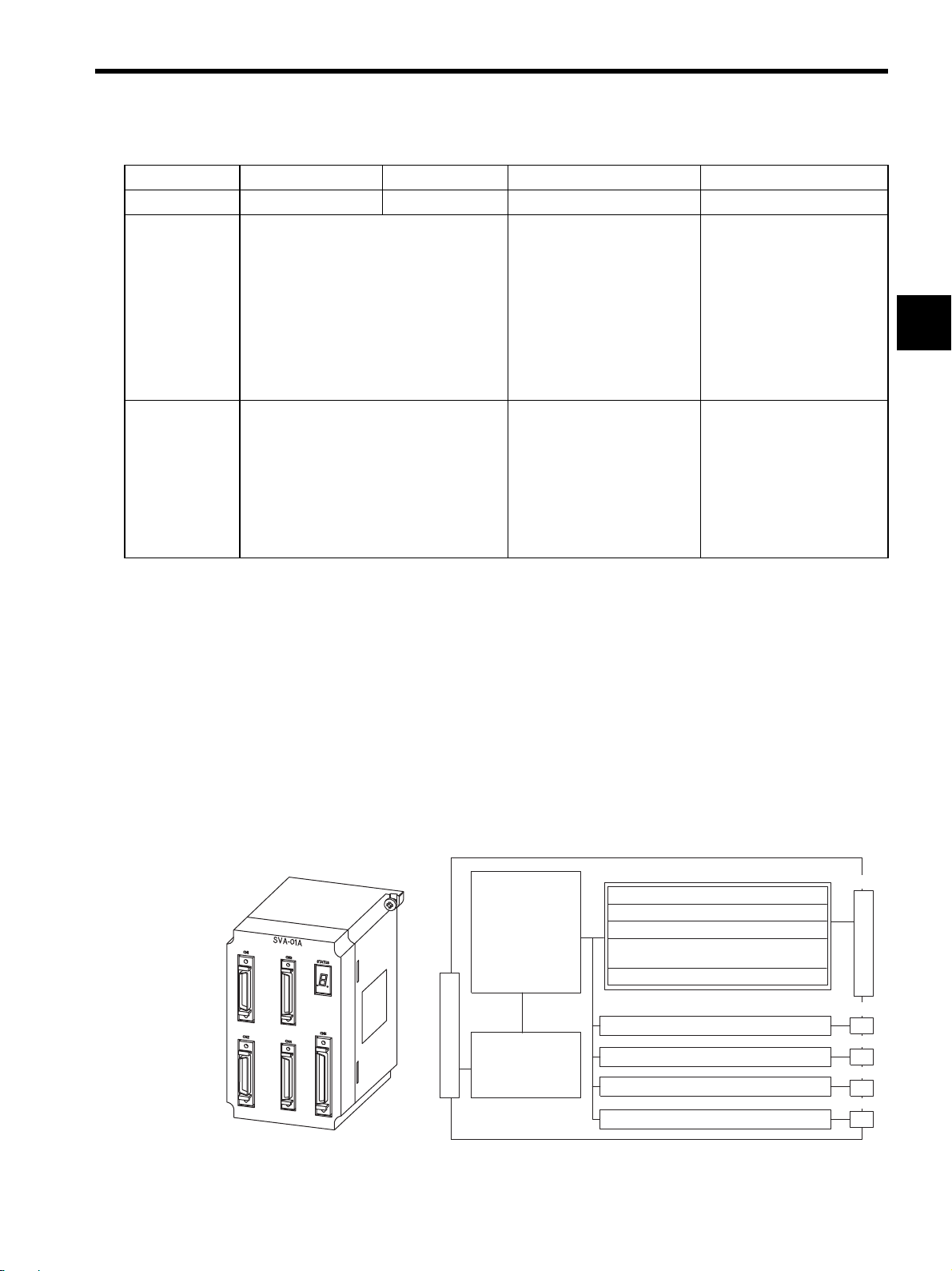
1.1.2 SVA-01A Module
Overview of the SVA-01A Module
The SVA-01A Module is a Motion Control Module with analog outputs. One SVA-01A
Module can control servos for up to four axes. Four connectors (CN1 to CN4) are provided
for connections to SERVOPACKs. Each connector is equipped with a speed reference ana-
log output, phase-A/B/C pulse inputs (5 V differential), a pulse latch digital input, and gen-
eral-purpose digital I/O signals. The CN5 connector is equipped with positive and negative
overtravel signals, deceleration limit inputs, zero point latch inputs, external positioning
latch inputs, brake control outputs, and other external I/O signals for four axes.
Motion Control
Speed control
Position control
Phase control
Zero point return
function
Monitor function
System Bus
Interface
Servo parameters
OW
System Bus Connector
IW
Analog output: Speed ref.
Pulse input: Phase A/B/C
General-purpose digital inputs (3) DI0 to D12
General-purpose digital outputs
Sensor ON output (5 V/24 V)
Same as above.
Same as above.
Same as above.
External (Field) I/O signals
NREF
(5) DO0 to DO2
DO4, DO5
SENS/DO3
CN1
Servo Connector
CN2
CN3
CN4
CN5
1-3
Page 18
1 Overview of Motion Modules
1.1.3 SVA-02A Module
Features of the SVA-01A Module
• Analog-output 4-axis Servo Module
• Independent position control, speed reference output, torque reference output, and phase
control are possible for each axis.
• Up to 60 axes (up to 15 Modules) can be controlled.
• Interpolations and complex processing operations can be easily programmed in motion
programs.
15 Modules max.
Inverters
Analog servos
SVA-01A
SGDA
SGDB
SGDM
SGDS
M M M M
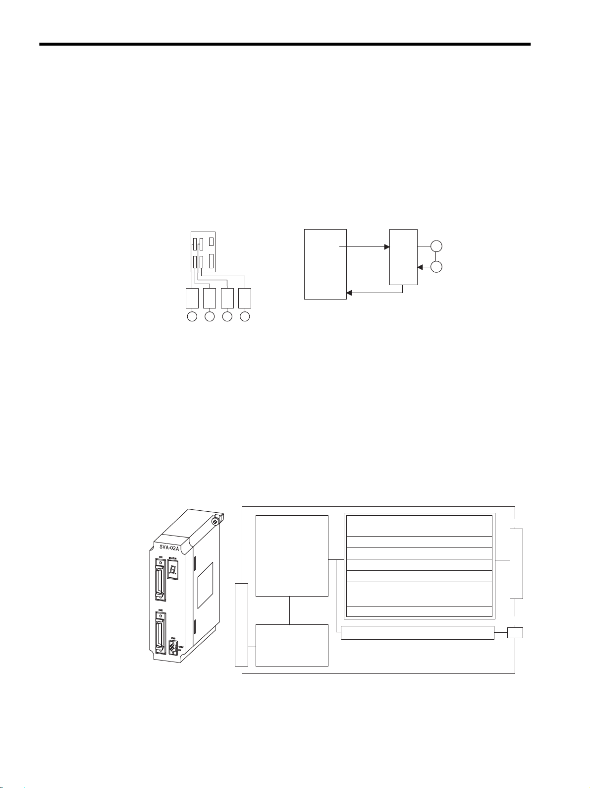
1.1.3 SVA-02A Module
Overview of the SVA-02A Module
The SVA-02A Module is a Motion Control Module with analog outputs. One SVA-02A
Module can control servos for up to two axes. Two connectors (CN1 and CN2) are provided
for connections to SERVOPACKs and external I/O devices. Each connector is equipped
with a speed reference analog output, a torque reference output, a torque monitoring analog
output, phase A/B/C pulse inputs (5 V differential), a pulse latch digital input, and general-
purpose digital I/O signals.
Speed, Position, and Phase Control
D/A
Speed
reference
Encoder
pulse
SERVOPAC K
SVA-01A
Counter
M
PG
Servo Control
Speed control
Position control
Torque control
Phase control
Zero point return
function
Monitor function
System Bus
Interface
Servo parameters
OW
System Bus Connector
IW
1-4
Analog outputs: Speed ref.
Positive torque ref.
Analog input: Speed monitor
Pulse input: Phase A/B/C
Pulse latch digital input
General-purpose digital inputs (5)+PI
General-purpose digital outputs (6)
Sensor ON output (5 V/24 V)
Same as above.
NREF
TLIMP
NREF
PIL
DI0 to DI5
DO0 to DO2
DO4, DO5
SENS/DO3
CN1
Servo Connector
CN2
Page 19
1.1 Module Overview and Features
SVA-02A
16 Modules max.
Inverters
Analog servos
SGDA
SGDB
SGDM
SGDS
MM
Speed, Position, and Phase Control
SVA-02A
M
PG
Speed reference
SERVOPACK
SERVOPACK
D/A
Counter
Counter
Torque control
D/A
Speed monitor
A/D
Encoder pulse
Torque reference
Speed control
Torque monitor
Encoder pulse
Torque Control
SVA-02A
M
PG
D/A
D/A
A/D
Features of the SVA-02A Module
• Analog-output 2-axis Servo Module
• Independent position control, speed reference output, torque reference output, and phase
control are possible for each axis.
• Up to 32 axes (up to 16 Modules) can be controlled.
• Interpolations and complex processing operations can be easily programmed in motion
programs.
1
1-5
Page 20
1 Overview of Motion Modules
CN1
System Bus Connector
MECHATROLINK Connector
MECHATROLINK
Control
Servo Control
Remote I/O Control
Inverter Control
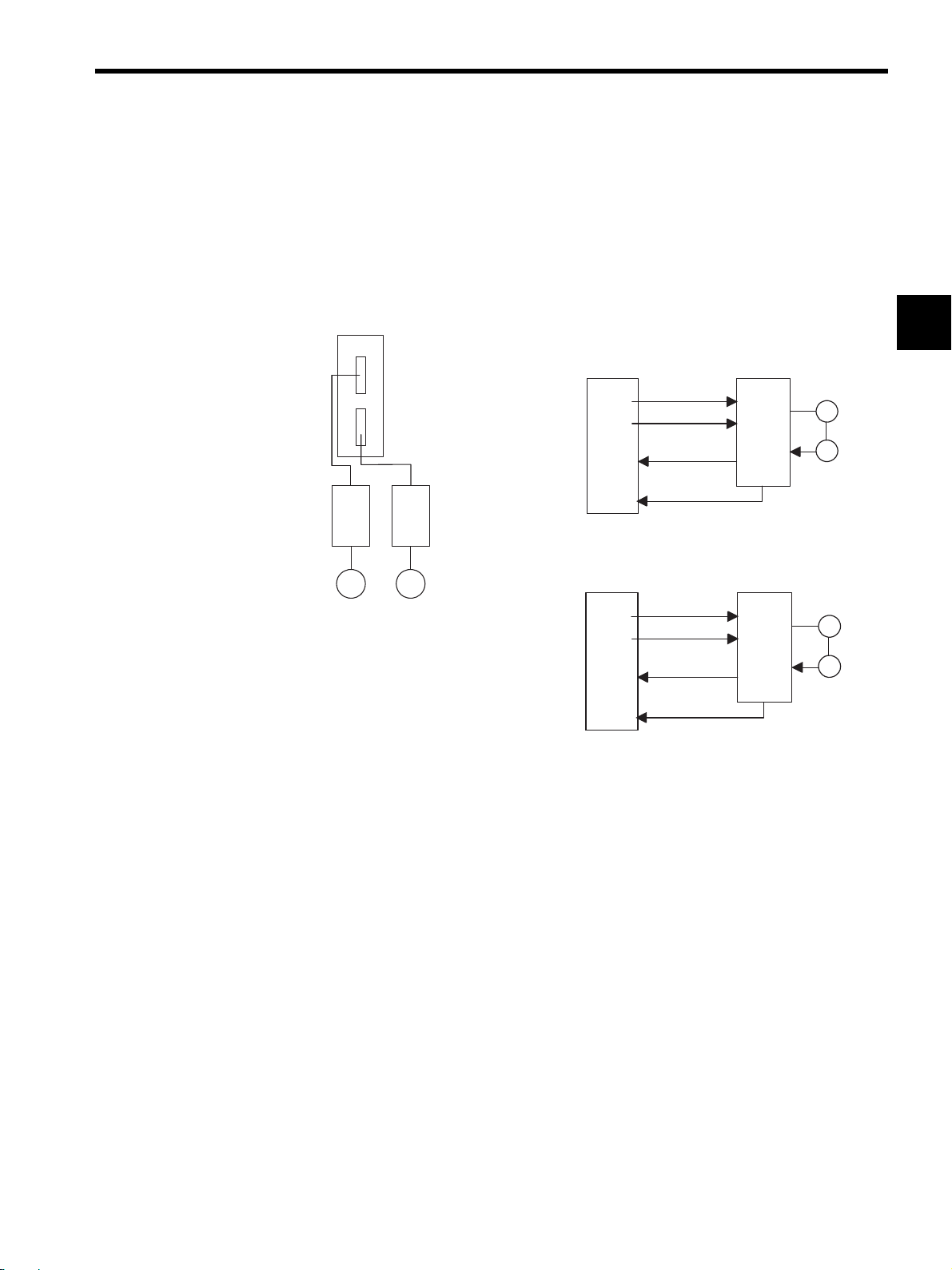
1.1.4 SVB-01 Module
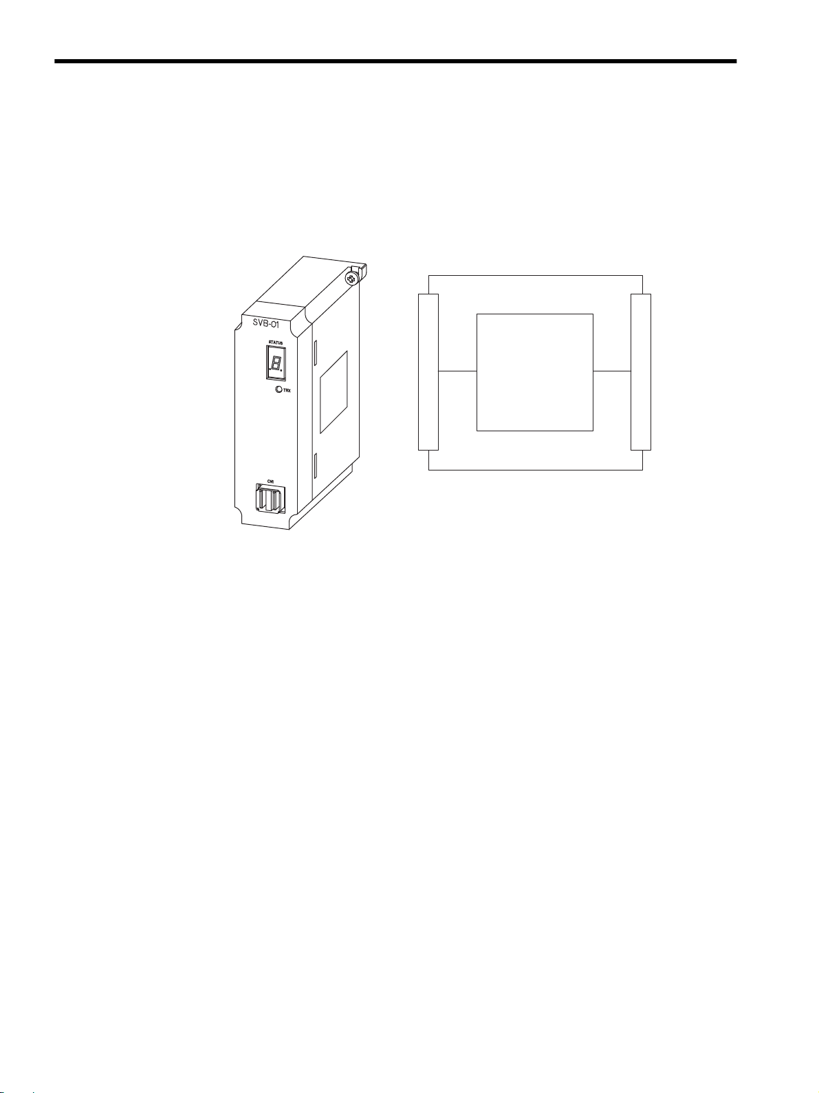
1.1.4 SVB-01 Module
Overview of the SVB-01 Module
The SVB-01 Module has a single MECHATROLINK connector and can control up to 14
Module Devices with MECHATROLINK interfaces.
The SVB-01 Module can be connected to I/O Modules (such as the JEPMC-IO350) or
Inverters (such as the VS-616G5 or VS-675H5) to transmit control signals and messages.
1-6
Page 21
1.1 Module Overview and Features
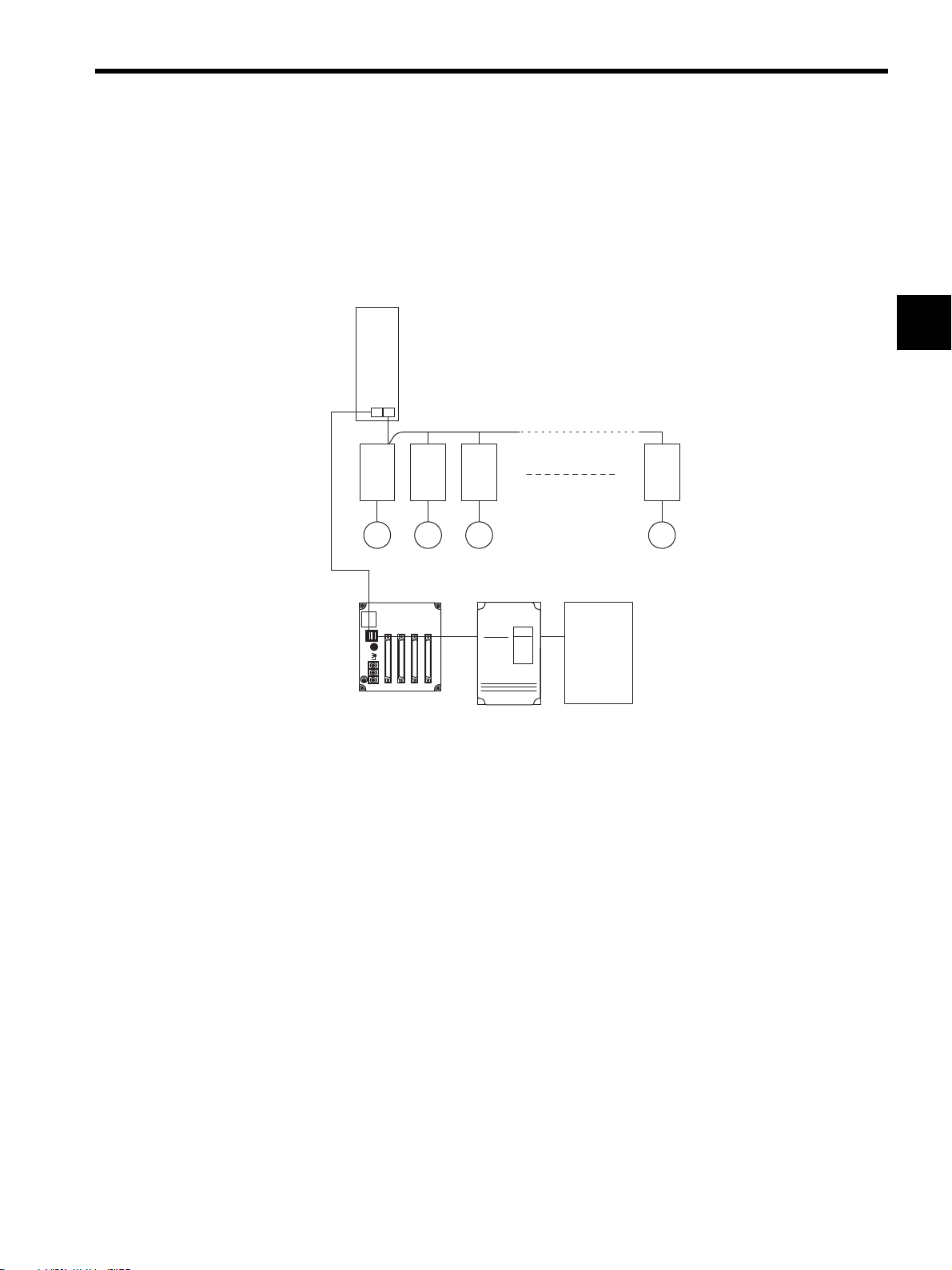
Features of the SVB-01 Module
• By using the MECHATROLINK high-speed field network interface, up to 14 axes can
be controlled with less wiring. A total of 224 axes can be controlled using a maximum
of 16 Modules.
• Using the position control functions, motion programs can perform positioning, zero
point returns, and interpolations.
SVB
16 Modules max.
SGD-N or SGDB-N
(connecting
14
stations
max.
M M M M
MECHATROLINKcompatible servos)
1
SW1
IN2
SW2 IN1
OUT2
OUT1
DC24V
DC 0V
YASKAWA
JEPMC-IO350
CN1
IN1 OUT1 IN2 OUT2
A1 A1 A1 A1B1B1 B1 B1
RIO
616G5
1-7
Page 22
1 Overview of Motion Modules
Motion functions
Override function
Stroke limit function
Emergency stop
function
CN2
CN1
System Bus Connector
Pulse Motor Driver
Connector
System Bus
Interface
Servo Parameters
OW
IW
Same as above.
2 Pulse-train Outputs:CCW
CW
1 Excitation ON
2 General-purpose
1 Excitation monitor/zero point
3 General-purpose
1 Emergency/deceleration stop
4 Digital Outputs:
5 Digital Inputs:
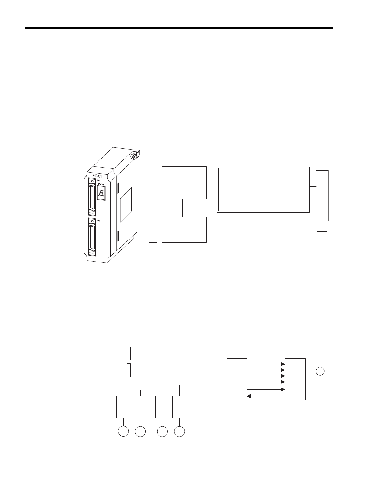
1.1.5 PO-01 Module
1.1.5 PO-01 Module
Overview of the PO-01 Module
The PO-01 Module is a Motion Control Module with pulse-train outputs. One PO-01 Mod-
ule can be connected to pulse motor drivers for up to 4 axes.
Two connectors (CN1 and CN2) are provided for connections to pulse motor drivers. Each
connector is equipped with a 5-V differential pulse-train output as well as 4 digital outputs
(DO) and 5 digital inputs (DI) for various pulse driver control applications.
Features of the PO-01 Module
• The PO-01 Module can be connected to up to four axes.
• A total of 64 axes can be controlled using a maximum of 16 Modules.
• This Module provides positioning, zero point returns, interpolations, and other functions,
all of which can be specified in motion programs.
PO-01
16 Modules max.
PO-01
M
M M M
Pulse Motor
Driver
1-8
CW+
CW-
CCW+
CCW-
DO
DI
Pulse
Motor
Driver
M
Page 23
1.2 System Configuration
ON
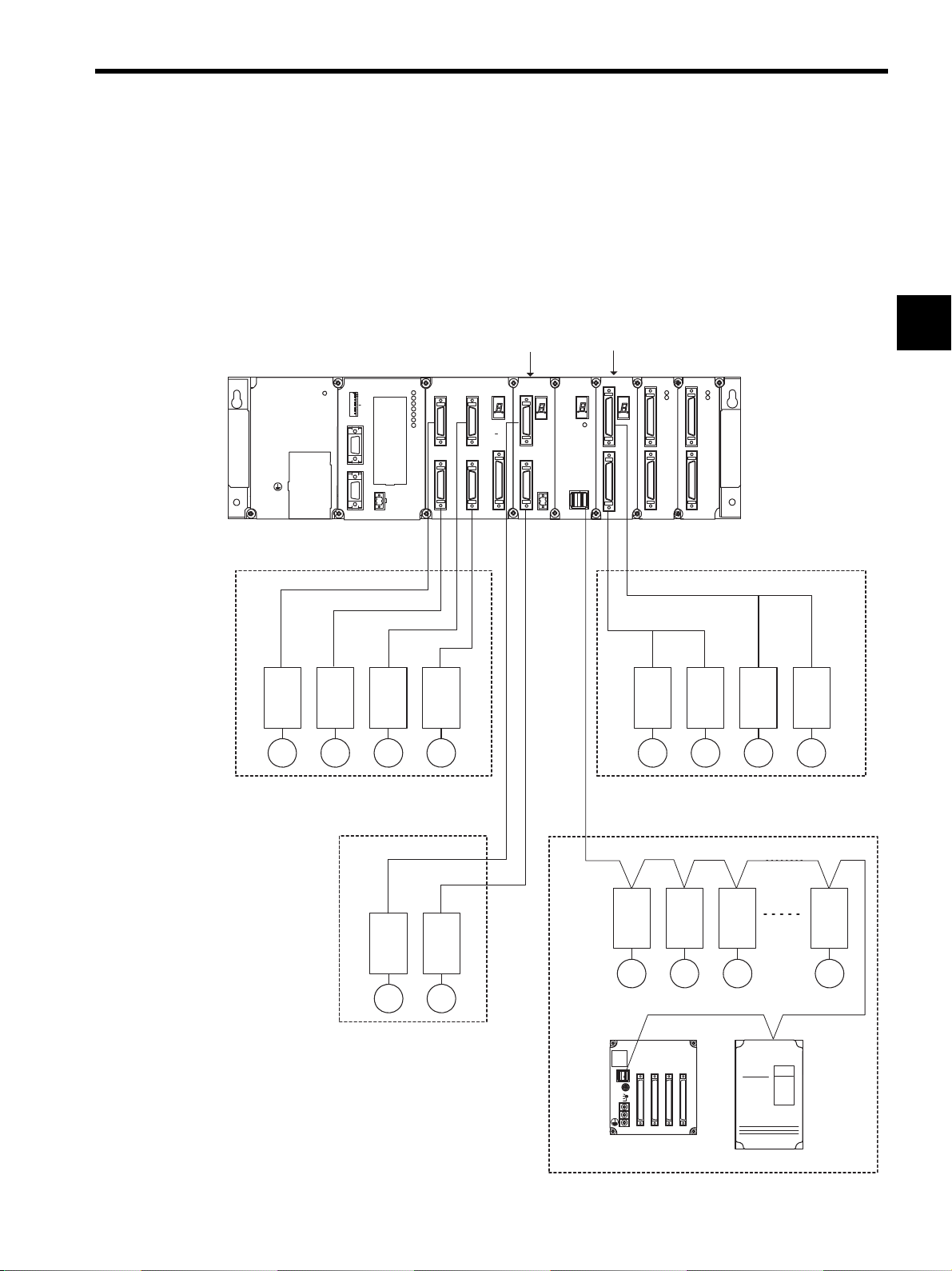
1.2.1 System Configuration Examples
The MP920 Motion Modules are available with analog outputs, pulse outputs, and field net-
work interfaces. Modules can be freely selected to configure the system best suited to the
application.
PS-03 SVA-01A
DC24V
TB1
+24V
0V
FG
SG
CPU-01
MP920 CPU-01PS-03
POWER
SW1
1
L.RST
BATTERY
2
RUN
3
INIT
4
TEST
5
6
MULTI
7
FLASH
8
M.RST
OFF
ON
PORT2
PORT1
CN1
RLY OUT
1.2 System Configuration
1
SVA-02A
SVA-01A
RDY
RUN
ALM
ERR
BAT
ALM
PRT2
PRT1
CN3
CN1
CN2
CN4
SVA-02A
CN1
STATUS
STATUS
CN5
CN2
CN3
SVB-01
SVB-01
+24V
0V
STATUS
CN1
PO-01
TRX
PO-01
LIO-01
LIO-01
CN1
CN1
STATUS
CN2
CN1
RUN
RUN
FUSE
FUSE
CN2
CN2
Analog outputs for 4 axes
Analog output for 2 axes
M M
Pulse outputs for 4 axes
Pulse Motor Driver
M M M MM M M M
MECHATROLINK communications
MECHATROLINK-compatible servos
M M M M
IO-350
216IF Inverter
Two analog outputs per axis
One analog input per axis
1-9
YASKAWA
JEPMC-IO350
CN1
IN1 OUT1 IN2 OUT2
SW1
IN2
SW2 IN1
OUT2
OUT1
DC24V
DC 0V
A1 A1 A1 A1B1B1 B1 B1
616G5
Up to 14 Modules can be connected.
Page 24

1 Overview of Motion Modules
1.3.1 General Specifications
1.3 Specifications
1.3.1 General Specifications
This section gives an overview of the specifications and functions of the MP920 Modules.
General Specifications of the MP920 Modules
Table 1.1 lists the general specifications of the MP920 Modules.
Table 1.1 General Specifications of the MP920 Modules
Item Specifications
Environmental
Conditions
Electrical
Operating
Conditions
Mechanical
Operating
Conditions
Installation
Requirements
Ambient Operating Temperature
Storage Temperature
Ambient Operating Humidity
Ambient Storage
Humidity
Pollution Level Pollution level 1 (conforming to JIS B 3501)
Corrosive Gas There must be no combustible or corrosive gas.
Operating
Altitude
Noise Resistance Conforming to JIS B 3502:
Vibration
Resistance
Shock
Resistance
Ground Ground to 100Ω max.
Cooling Method Natural cooling
0 to 55°C
-20 to 85°C
30% to 95% RH (with no condensation)
5% to 95% RH (with no condensation)
2,000 m above sea level or lower
1,500 V (p-p) in either normal or common modes with a
pulse width of 100 ns/11μs and a rise time of 1 ns (tested
with impulse noise simulator)
Conforming to JIS B 3502:
10 to 57 Hz with single-amplitude of 0.075 mm
57 to 150 Hz with fixed acceleration of 9.8 m/s
10 sweeps each in X, Y, and Z directions
(sweep time: 1 octave/min)
Conforming to JIS B 3502:
2
Peak acceleration of 147 m/s
the X, Y, and Z directions
(15G) twice for 11 ms each in
2
(1G)
1-10
Page 25
1.3 Specifications
1.3.2 Function Lists
Table 1.2 lists the motion control function specifications for the MP920.
Table 1.2 MP920 Motion Control Function Specifications
Item Specification
Description SVA-01A SVA-02A SVB-01 PO-01
Model Number
Interface
Number of Controlled Axes per Module
Maximum Number of Modules
Control
Specifications
Reference Unit mm, inch, deg, pulse
Reference Unit Minimum Setting 1, 0.1, 0.01, 0.001, 0.0001, 0.00001
Maximum Programmable Value -2147483648 to +2147483647 (signed 32-bit value)
Speed Reference Unit mm/min, inch/min, deg/min, pulses/min
Acceleration/Deceleration Type Linear, asymmetric, S-curve, exponential
Override Function Positioning: 0.01% to 327.67% by axis
Coordinate System Rectangular coordinates
Zero
Point
Return
Programs
PTP Control Linear, rotary, infinite-length, and independent axes
Interpolation Up to 16 linear axes, 2 circular axes, and 3 helical axes
Speed Reference Output
Torque Reference Output
Phase Control
Position
Control
DEC1 + Phase-C
DEC2 + Phase-C
DEC1 + LMT + C
Phase-C
DEC1 + ZERO
DEC2 + ZERO
DEC1 + LMT + ZERO
ZERO
Language Special motion language, ladder logic program
Number of Tasks Up to eight programs can be executed in parallel.
Number of Programs Up to 256
Program Capacity 80 Kbytes
Positioning
External Positioning
Zero Point Return
Interpolation
Interpolation with
Position Detection
Fixed-speed Feed
Fixed-length Feed
JEPMC-MC200A JEPMC-MC220A JEPMC-MC210 JEPMC-PL210
Analog Analog MECHATROLINK Pulse
4 2 14 4
15 16 16 16
Yes Yes No No
No Yes No No
Yes Yes No No
Ye s Ye s Yes Ye s
Ye s Ye s Yes N o
Ye s Ye s Yes Ye s
Ye s Ye s Yes Ye s
Ye s Ye s Yes N o
Ye s Ye s Yes Ye s
Ye s Ye s Yes Ye s
Interpolation: 0.01% to 327.67% by group
Ye s Ye s Yes N o
Yes Yes No No
Yes Yes No No
Ye s Ye s Yes N o
Ye s N o Ye s Ye s
Ye s N o No Ye s
Ye s N o No Ye s
Ye s N o Ye s N o
1
1-11
Page 26

1 Overview of Motion Modules
1.3.2 Function Lists
Table 1.2 MP920 Motion Control Function Specifications (cont’d)
Item Specification
Description SVA-01A SVA-02A SVB-01 PO-01
Applicable SERVOPACKs and Inverters SERVOPACKs
• SGDA-S
• SGDB-
• SGDM-
• SGDS-
Inverters
SERVOPACKs
• SGDA-S
• SGDB-
• SGDM-
• SGDS-
Inverters
SERVOPACKs
• SGD-N
• SGDB-AN
• SGDH-
E+
JUSP-NS100
Pulse Motor
Drivers
Inverters (216IF
board required)
• VS-616G5
• VS-676H5
• VS-676H5T
Encoder Incremental or
absolute
Incremental or
absolute
Incremental or
absolute
No
Note: Yes: Can be controlled, No: Cannot be controlled.
1-12
Page 27

2
Motion Control
This chapter gives an overview of motion control and describes the motion
commands.
2.1 Overview of Motion Control - - - - - - - - - - - - - - - - - - - - - - - - 2-2
2.1.1 Motion Control for the MP920 - - - - - - - - - - - - - - - - - - - - - - - - - - - - 2-2
2.1.2 Motion Control Methods - - - - - - - - - - - - - - - - - - - - - - - - - - - - - - - - 2-4
2.1.3 Examples of Motion Control Applications - - - - - - - - - - - - - - - - - - - - 2-5
2.2 Control Modes - - - - - - - - - - - - - - - - - - - - - - - - - - - - - - - - -2-7
2.2.1 Overview of Control Modes - - - - - - - - - - - - - - - - - - - - - - - - - - - - - - 2-7
2.2.2 Speed Reference Output Mode - - - - - - - - - - - - - - - - - - - - - - - - - - - 2-8
2.2.3 Torque Reference Output Mode - - - - - - - - - - - - - - - - - - - - - - - - - - 2-12
2.2.4 Phase Control Mode - - - - - - - - - - - - - - - - - - - - - - - - - - - - - - - - - - 2-15
2.2.5 Zero Point Return Mode - - - - - - - - - - - - - - - - - - - - - - - - - - - - - - - 2-22
2
2.3 Position Control - - - - - - - - - - - - - - - - - - - - - - - - - - - - - - - 2-26
2.3.1 Prerequisites for Position Control - - - - - - - - - - - - - - - - - - - - - - - - - 2-26
2.3.2 Position Control Without Using Motion Commands - - - - - - - - - - - - 2-41
2.4 Position Control Using Motion Commands - - - - - - - - - - - - 2-45
2.4.1 Overview of Motion Commands - - - - - - - - - - - - - - - - - - - - - - - - - - 2-45
2.4.2 Positioning (POSING) - - - - - - - - - - - - - - - - - - - - - - - - - - - - - - - - - 2-48
2.4.3 External Positioning (EX_POSING) - - - - - - - - - - - - - - - - - - - - - - - 2-51
2.4.4 Zero Point Return (ZRET) - - - - - - - - - - - - - - - - - - - - - - - - - - - - - - 2-55
2.4.5 Interpolation (INTERPOLATE, END_OF_INTERPOLATE) - - - - - - - 2-70
2.4.6 Interpolation with Position Detection (LATCH) - - - - - - - - - - - - - - - - 2-73
2.4.7 Fixed Speed Feed (FEED) - - - - - - - - - - - - - - - - - - - - - - - - - - - - - - 2-74
2.4.8 Fixed Length Feed (STEP) - - - - - - - - - - - - - - - - - - - - - - - - - - - - - 2-77
2.4.9 Zero Point Setting (ZSET) - - - - - - - - - - - - - - - - - - - - - - - - - - - - - - 2-81
2-1
Page 28
2 Motion Control
M
M
M
M
M
Operation
panel
I/O
processing
Ladder logic program
SERVOPACK
Inverter
Pulse motor
driver
Sequence
control
Analog Module
Analog Device
Motion control
MC program
Communications
control
Programming
Device
Other
company's
sequencer
I/O Module
Motion Module
Communications
Module
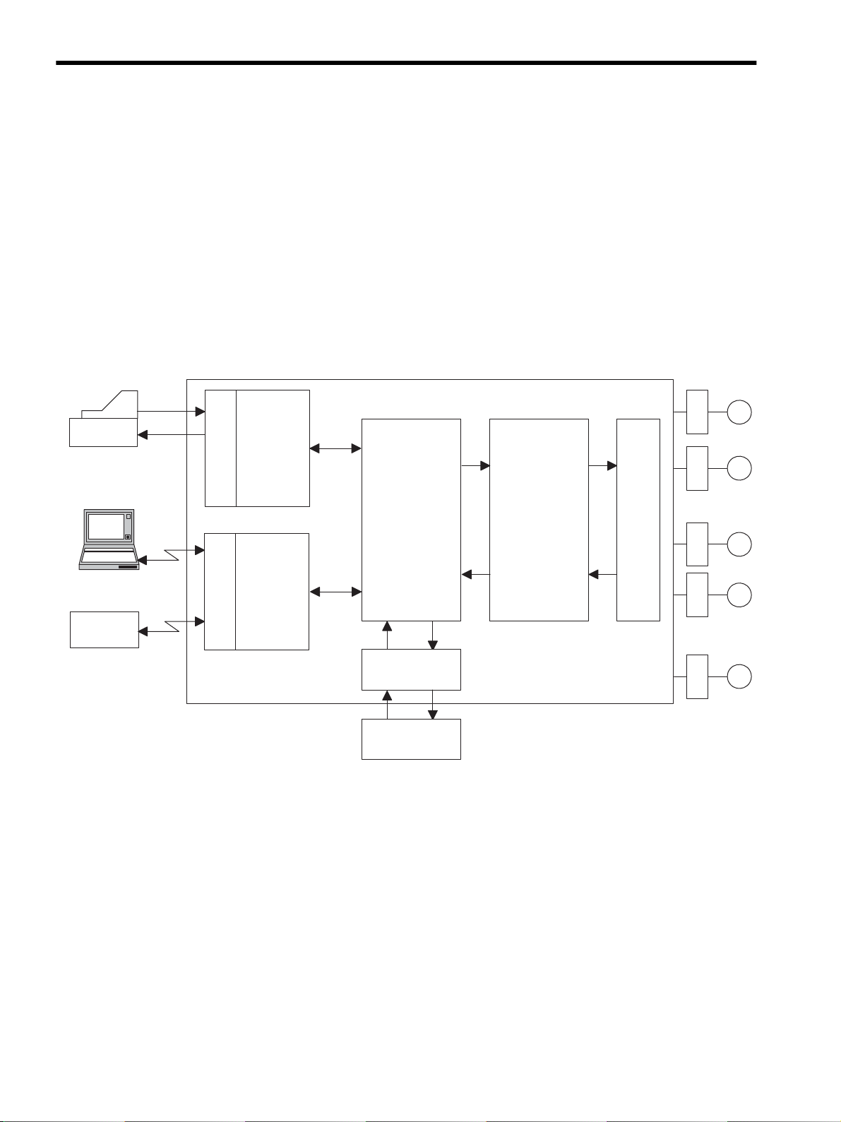
2.1.1 Motion Control for the MP920
2.1 Overview of Motion Control
This section describes the methods used for motion control and gives some examples of their
use.
2.1.1 Motion Control for the MP920
The MP920 Machine Controller provides fully integrated sequence control and motion con-
trol.
The following diagram shows a conceptual diagram of the MP920 system.
A wide range of Motion Modules is provided for the MP920, and these can be selected
according to the purpose.
The following table shows the types of Motion Module and their features.
2-2
Page 29
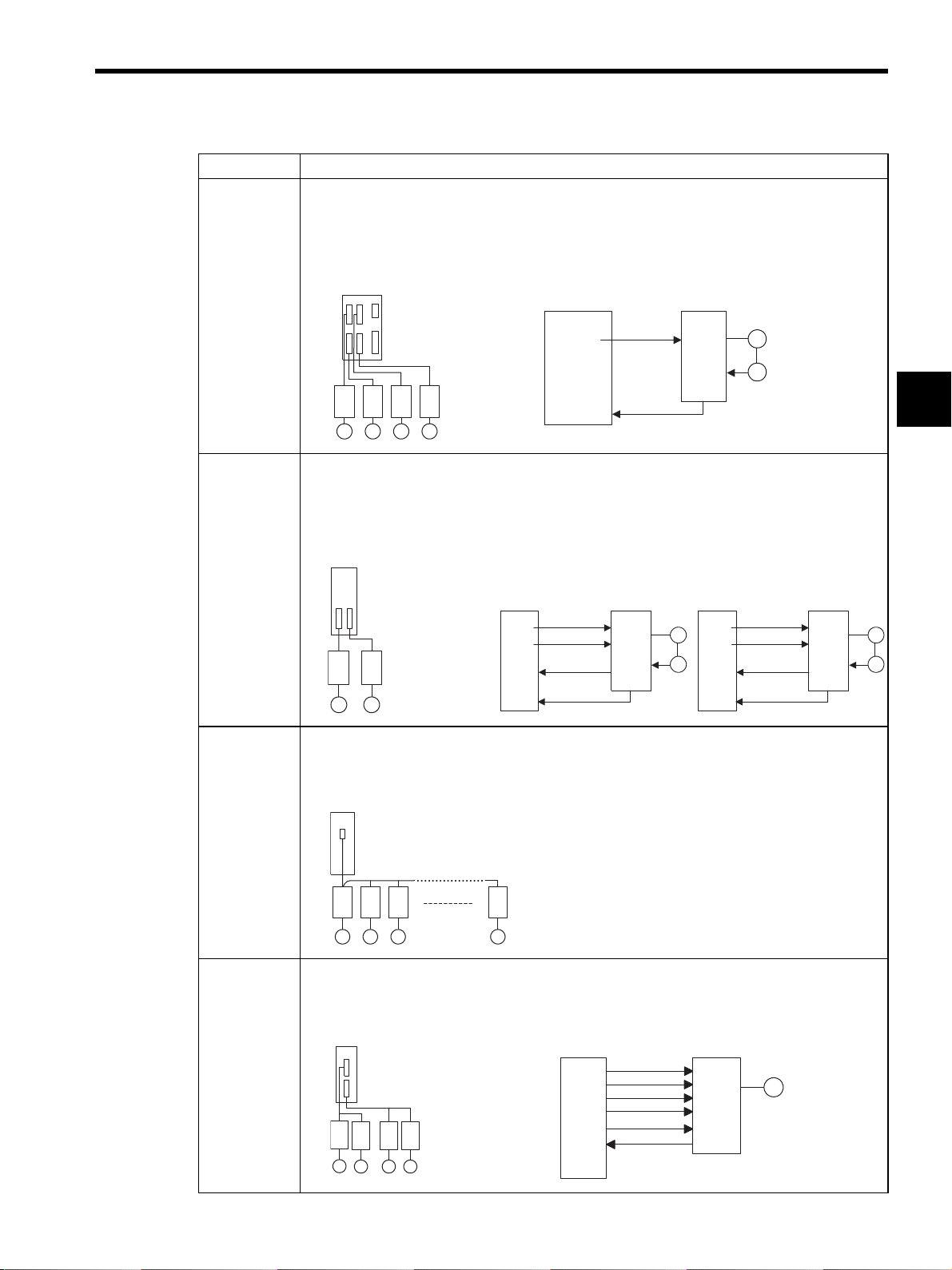
Name Features
r
PO-01
M
M
16 Modules max.
Pulse motor driver
M M
PO-01
M
CW+
CCW+
DI
CW-
CCW-
DO
Pulse
motor
driver
SVA-01A • Analog-output 4-axis Servo Module
• Independent position control, speed control, and phase control are possible for each axis.
• Up to 60 axes (up to 15 Modules) can be controlled.
• Interpolations and complex processing operations can be easily programmed in motion programs.
15 Modules max.
SVA-01A
Inverters
Analog servos
SGDA-S
Speed, position, and phase control
SVA-01A
SGDB
SGDM
M M M M
SVA-02A • Analog-output 2-axis Servo Module
• Independent position control, speed control, torque, and phase control are possible for each axis.
• Up to 32 axes (up to 16 Modules) can be controlled.
• Interpolations and complex processing operations can be easily programmed in motion programs.
D/A
Counter
Speed
reference
Encoder
Pulse
2.1 Overview of Motion Control
SERVOPACK
M
PG
2
16 Modules max.
SVA-02A
Inverters
Analog servos
SGDA-S
SGDB
SGDM
M M
Speed, position, and phase control
SVA-02A
D/A
D/A
A/D
Counter
Speed reference
Torque limit
Speed monitor
Encoder
Pulse
SERVOPACK
Torque control
SVA-02A
Torque reference
D/A
M
PG
Counter
D/A
A/D
Speed limit
Torque monitor
Encoder
Pulse
SERVOPACK
SVB-01 • By using the high-speed field network (MECHATROLINK) interface, up to 14 axes can be con-
trolled with less wiring. (Using a maximum of 16 Modules, 224 axes can be controlled.)
• Using the position control functions, motion programs can perform positioning, zero point
returns, and interpolations.
SVB
16 Modules max.
14 axes max.
SGD-N o
SGDB-N
M M M M
PO-01 • Pulse output type 4-axis Pulse Output Module
• Up to 64 axes (up to 16 Modules) can be controlled.
• Using the position control functions, motion programs can perform positioning, zero point
returns, and interpolations.
M
PG
2-3
Page 30
2 Motion Control
H0101 OWC000
B00105
IFON
500 OWC015
0 OWC015
ELSE
Ladder logic program
Motion
processing
Setting Parameters
Monitoring Parameters
CPU Module SVA Module
SERVO-
PACK
PGM
PGM
PGM
PGM
Status
Status
information
SERVO-
PACK
SERVO-
PACK
SERVO-
PACK
2.1.2 Motion Control Methods
2.1.2 Motion Control Methods
By using Motion Modules, motions for a wide variety of applications can be controlled.
There are two programming methods for controlling motions: Ladder logic programs and
motion programs. An overview of each programming method is given below.
Ladder Logic Programming
Ladder logic programs are designed mainly for sequence control. The motion setting param-
eters and motion monitoring parameters used as interfaces with the Motion Modules are
directly written to and read by the ladder logic programs to perform motion control.
Special operations can be programmed and combined as user functions. For details, refer to
Chapter4 Parameters and the section describing the parameters of each Motion Module.
Motion Programming
The motion programs that have been created using a special motion language perform
motion control. Up to 256 programs can be created, and these can also be executed in paral-
lel.
The use of the special motion language enables complex operations to be easily pro-
grammed. The system performs command end checks and other processing. The special
motion commands shown in the following table are provided as standard in the MP9
Series.
CPU Module
MSEE MPM001
CPU Module SVA Module
Motion program
MOV [X] 100
MVS [X] 100
MCC - - - EXT
Setting Parameters
MOV
command
MOV
command
MOV
command
Monitoring Parameters
Command
processing
Status
information
2-4
SERVO-
PACK
SERVO-
PACK
SERVO-
PACK
SERVO-
PACK
PGM
PGM
PGM
PGM
Page 31

2.1 Overview of Motion Control
Commands
Axis move commands: 8 types
MOV, MVS, MCW, MCC, ZRN, SKP, MVT, EXM
Basic control commands: 6 types
ABS, INC, POS, PLN, MVM, PLD
Speed and acceleration/deceleration commands: 7 types
ACC, DCC, SCC, VEL, IAC, IDC, IFP, FMX
High-level control commands: 4 types
PFN, INP, SNG, UFC
Control commands: 10 types
MSEE, TIM, IOW, END, RET, EOX, IF ELSE IEND, WHILE WEND,
PFORK JOINTO PJOINT, SFORK JOINTO SJOINT
Math and sequence control commands: 32 types
=. +. -, *, /, MOD, |, ^, &, !, ( ), S{ }, R { }, SIN, COS, TAN, ASN, ACS,
ATN, SQRT, BIN, BCD, = =, < >, >, <, >=, <=, SFR, SFL, BLK, CLR
2.1.3 Examples of Motion Control Applications
The following illustrations show examples of the use of each control mode for Motion Mod-
ules.
Speed Reference Output Control and Torque Reference Output
Control
2
Winder A
Tension setting
Winder B
Servomotor
Tension
Servomotor
detector
MP920
Speed limit
SERVOPACK
Tension rollers
Servomotor
MP920
2-5
Page 32

2 Motion Control
Servomotor
MP920
Y axis
Z axis
X axis
C axis
A axis
2.1.3 Examples of Motion Control Applications
Phase Control
Conveyor Synchronization
Position Control
Conveyor
Coater
2-6
Page 33

2.2 Control Modes
This section describes the motion control modes that can be used by the MP920.
2.2.1 Overview of Control Modes
Five control modes are available for MP920 Motion Modules. These modes can be switched
in real time, according to the purpose.
The following table shows the control mode that can be used by MP920 Motion Modules,
and gives an overview and some examples of their uses.
Control Mode Overview Typical
Speed Reference
Output Mode
Torque Reference
Output Mode
Position Control
Mode*
Phase Control
Mode
Zero Return
Mode*
Rotates the motor at the
specified speed.
Outputs the specified torque. Injection mold-
Specifies the target position
and speed. Executes a position loop, identifies the difference to the target position
from the encoder, converts
the difference to the speed
reference, and performs
position control.
While executing speed control using a standard speed
reference, generates the target position from the speed
reference, and performs
phase control.
Performs zero point positioning when an incremental
encoder is used.
Module
Applications
Conveyors or
main axes
ing machines or
presses
Conveyors or
XY tables
Electronic cams
or electronic
shafts
− Yes Yes No No
SVA-
SVA-
01A
Yes Yes No No
YesYesYesYes
Yes Yes No No
02A
No Yes No No
2.2 Control Modes
2
SVB-01PO-
01
* There are two methods for returning to the zero point:
• Using ZERO POINT RETURN command for position control
• Using Zero Return Mode
Note: Yes: Available, No: Not available
2-7
Page 34

2 Motion Control
2.2.2 Speed Reference Output Mode
2.2.2 Speed Reference Output Mode
Overview
This mode is used to rotate the motor at the desired speed.
A speed reference is output to the servo drive according to the specified speed reference, lin-
ear acceleration/deceleration time constant, and filter time constant.
The acceleration/deceleration time can be set as desired.
S-curve acceleration/deceleration can be easily performed by the user program (one com-
mand).
The speed reference output mode can also be used for a general-purpose D/A converter. In
this case, set the linear acceleration/deceleration time constant and the filter time constant to
“0.”
IMPORTANT
The speed reference output mode is available only with the SVA-01A and SVA-02A Modules. It can-
not be used with the SVB-01 and PO-01 Modules.
Details
Use the following procedure to perform operation in the speed reference output mode.
1. Set the motion fixed parameters.
2. Set the motion setting parameters.
Set the speed reference output mode (NCON).
3.
4. Set the RUN command (RUN) to ON.
Output the speed reference and torque limit reference*
5.
Set the speed reference output mode to OFF.
*: SVA-02A Module only
: System execution
: User settings
NCON
RUN
Speed
(%)
(100%)
Speed
reference
0
Linear acceleration time constant Linear deceleration time constant
Time (t)
2-8
Page 35

2.2 Control Modes
1. Set the motion fixed parameters according to the user’s machine.
Table 2.1 Examples of Fixed Parameters
No. Name Setting Range Meaning Setting
Example
7 Rated Motor Speed Setting 1 to 32000 Rated motor speed
8 Number of Feedback Pulses per
Motor Rotation
9 D/A Output Voltage at 100%
Speed
Number of Feedback Pulses per
Motor Rotation
(For high-resolution) *
10 D/A Output Voltage at 100%
Torque Limit*
* 1. Valid only with an SVB-01 Module.
* 2. Valid only with an SVA-02A Module.
2
1
4 to 65532 Number of pulses
before multiplication
0.001 to 10.000 0.001 = 0.001 V
1 = 1 V
4 to 2147483647 1 = 1 pulse/rev 2048 pulses/
0.001 to 10.000 0.001 = 0.001 V
1 = 1 V
3000 min
2048
6.000 V
rev
3.000 V
2. Set the motion parameters to be used in the speed reference output mode.
The following three methods can be used to set the motion setting parameters.
-1
2
• Using the MPE720 Setting Parameter Window
• Using a ladder logic program
• Using a motion program
Name Register No. Setting
Positive Torque Limit
Setting (TLIMP)*
Positive Speed Limiter Setting (NLIMP)
Negative Speed Limiter Setting (NLIMN)
Linear Acceleration
Time Constant
(NACC)
Linear Deceleration
Time Constant
(NDEC)
Filter Time Constant
Setting (NNUM)
Speed Reference
Setting (NREF)
Table 2.2 Examples of Setting Parameters
Meaning Setting
Range
OW02 -327.68 to
327.67
OW04 0.00 to
327.67
OW05 0 to 327.67 0.01 = 0.01%
OW0C 0 to 32767 Linear acceleration time con-
OW0D 0 to 32767 Linear deceleration time
OW14 0 to 255 For simple S-curve accelera-
OW15 -327.68 to
327.67
0.01 = 0.01%
1 = 1%
0.01 = 0.01%
1 = 1%
1 = 1%
stant (ms) at speed pattern
generation
constant (ms) at speed pattern generation
tion
Speed reference value
0.01 = 0.01%
1 = 1%
Example
-100.00
(-100.00%)
130.00
(130.00%)
130.00
(130.00%)
1000
(1 second)
1000
(1 second)
0
50.00
(50.00%)
* Valid only with an SVA-02A Module.
In the examples, SERVOPACK is used as axis 1 of Module No. 1. When the Module
number and the axis number are different, see 4.1.2 Modules and Motion Parameter
Registers, and change the register numbers.
3. Select the Speed Reference Output Mode (NCON) (bit 0 of OW00).
2-9
Page 36

2 Motion Control
0
NACC
Speed reference
1 second 1 second
NACC Time (t)
Speed
(%)
NR
(100%)
NREF
(50%)
2.2.2 Speed Reference Output Mode
User Program Examples
4. To start operation, set the Servo ON (RUN) to ON (bit 0 of OW01).
The speed reference will be output for the axis according to the specified motion param-
eters.
With an SVA-02A Module (2-axis), the speed reference is output with an NREF signal
from channel 1 (or channel 2), and the torque limit reference is output with an AO-OUT
signal.
Even while the speed reference output mode is being selected, the motion parameter set-
tings can be changed.
5. To stop operation, set the RUN command (RUN) and the speed reference output mode
(NCON) to OFF.
Example of RUN Operation
Fig. 2.1 Speed Pattern
2-10
Page 37

Ladder Logic Program Example
2.2 Control Modes
H0101
RUNPB
IB00104
ACCEL
IB00105
IFON
500
ELSE
0
IEND
DEND
RUNMOD
OWC000
RUN
OBC0010
NREF
OWC015
NREF
OWC015
Set the speed reference output mode to ON.
Driver RUN command (RUN)
When IB00104 turns ON, the speed
reference output mode starts.
When the acceleration command (IB00105)
turns ON, a speed reference of 50% is
output for the acceleration time constant
(ACC).
When IB00105 turns OFF, the deceleration
time constant (DEC) causes deceleration
stop (a speed reference of 0% is output).
Fig. 2.2 RUN Commands (DWG H01)
The example in the above illustration has been greatly simplified. In actual operation, each
register can be controlled from the user program.
2
2-11
Page 38

2 Motion Control
2.2.3 Torque Reference Output Mode
2.2.3 Torque Reference Output Mode
Overview
This mode is used to generate a constant torque, regardless of the speed.
Select this mode to keep the metal mold of a plastic molding machine, such as an injection
molding machine, at a constant pressure.
When the torque reference output mode is selected, the specified torque reference and speed
limit reference are output by the servo drive.
This mode can be used only with an SVA-02A Module.
IMPORTANT
The torque reference output mode is available only with the SVA-02A Module. It cannot be used with
the SVA-01A, SVB-01, and PO-01 Modules.
Details
Use the following procedure to perform operations in the torque reference output mode.
1. Set the motion fixed parameters.
2. Set the motion setting parameters.
Set the torque reference output mode (TCON)
3.
4. Set the RUN command (RUN) to ON.
Output the torque reference and speed limit reference.
5.
Set the torque reference output mode to OFF.
: System execution
: User settings
TCON
RUN
.
Torque speed
(%)
Torque reference
0
Time (t)
2-12
Page 39

2.2 Control Modes
1. Set the motion fixed parameters according to the user’s machine.
Table 2.3 shows the related parameters when the torque reference output mode is used.
Table 2.3 Examples of Fixed Parameters
No. Name Setting Range Meaning Setting
Example
7 Rated Motor Speed Setting 1 to 32000 Rated motor speed
8 Number of Feedback Pulses per
Motor Rotation
9 D/A Output Voltage at 100%
Speed
Number of Feedback Pulses per
Motor Rotation
(For high-resolution)
10 D/A Output Voltage at 100%
Torque Limit
* 1. Valid only with an SVB-01 Module.
* 2. Valid only with an SVA-02A Module.
*1
*2
4 to 65532 Number of pulses
before multiplication
0.001 to 10.000 0.001 = 0.001 V
1 = 1 V
4 to 2147483647 1 = 1 pulse/rev 2048 pulses/
0.001 to 10.000 0.001 = 0.001 V
1 = 1 V
3000 min
2048
6.000 V
rev
3.000 V
2. Set the motion parameters to be used in the torque reference output mode.
-1
2
Table 2.4 Examples of Setting Parameters
Name Register No. Meaning Setting
Example
Torque Reference
Setting (TREF)
Speed Limit Setting
(NLIM)
OW1B Sets the torque reference value at
0.01%.
OW1C Sets the speed limit value at 0.01%. 50.00
50.00
(50.00%)
(50%)
3. Select the Torque Reference Output Mode (TCON) (bit 1 of OW00).
4. To start operation, set the RUN Servo ON (RUN) to ON (bit 0 of OW01).
The torque reference and the speed limit reference will be output for the axis according
to the specified motion parameters.
Even while the torque reference output mode is being selected, the motion parameter
settings can be changed.
5. To stop operation, set the RUN command (RUN) and the torque reference output mode
(TCON) to OFF.
2-13
Page 40

2 Motion Control
2.2.3 Torque Reference Output Mode
User Program Example
Example of RUN Operation
Torque
(%)
TREF
0
Torque reference
Fig. 2.3 Torque Pattern
Ladder Logic Program Example
H0102
RUNPB
IB00204
IB00205
IFON
5000
ELSE
RUNMOD
OWC040
RUN
OBC0410
TREF
OWC05B
Time (t)
Set the torque reference output mode to ON.
Driver RUN command (RUN)
When IB00204 turns ON, the torque
reference output mode starts.
When IB00205 turns ON, 50% is output as
the torque reference.
When IB00205 turns OFF, 0% is output as
the torque reference.
0
IEND
DEND
TREF
OWC05B
Fig. 2.4 RUN Commands (DWG H02)
The example in the above illustration has been greatly simplified. In actual operation, each
register can be controlled from the user program.
2-14
Page 41

2.2.4 Phase Control Mode
Overview
This mode is used to rotate the motor according to the specified speed reference, and at the
same time to strictly control the number of rotations.
Phase control uses multiple axes, ensuring that no deviation occurs in the angle of rotation
(phase) for the motors and enabling endless rotation for printing and other machines being
controlled.
Electronic shafts and electronic cams can thus be used in the servomotors of complex
machine configurations. Phase alignment and synchronous operation, as well as ratio opera-
tion and cam variable speed operation have all been replaced by software.
2.2 Control Modes
2
IMPORTANT
Using a machine to perform conventional
synchronous operation
(Line shaft and cam system)
Controller
Driver
Gear
No.1 roll No.2 roll Cam machine
Fig. 2.5 Electronic Cam and Electronic Shaft Illustration
The phase control mode is available only with the SVA-01A and SVA-02A Modules. It cannot be used
with the SVB-01 and PO-01 Modules.
Gear Gear
M
Cam
Using the MP920 to perform synchronous
operation (Electronic shaft and electronic
cam system)
MP920
Driver
MMM
No.1 roll No.2 roll
Cam machine
2-15
Page 42

2 Motion Control
2.2.4 Phase Control Mode
Details
Use the following procedure to perform phase control operation.
1. Set the motion fixed parameters.
2. Set the motion setting parameters.
3.
Select the phase control mode (PHCON).
4. Set the RUN command (RUN) to ON.
Phase control operation is performed.
5.
Set the phase control mode to OFF.
: System execution
: User settings
PCON
RUN
Speed (%)
(100%)
Reference
speed
Position
0
Time (t)
2-16
Page 43

2.2 Control Modes
1. Set the motion fixed parameters according to the user’s machine.
Table 2.5 Examples of Fixed Parameters
No. Name Setting Range Meaning Setting
Example
7 Rated Motor Speed Setting 1 to 32000 Rated motor speed
8 Number of Feedback Pulses per
Motor Rotation
9 D/A Output Voltage at 100%
Speed
Number of Feedback Pulses per
Motor Rotation
(For high-resolution)
10 D/A Output Voltage at 100%
Torque Limit
* 1. Valid only with an SVB-01 Module.
* 2. Valid only with an SVA-02A Module.
*1
*2
4 to 65532 Number of pulses
before multiplication
0.001 to 10.000 0.001 = 0.001 V
1 = 1 V
4 to 2147483647 1 = 1 pulse/rev 2048 pulses/
0.001 to 10.000 0.001 = 0.001 V
1 = 1 V
3000 min
2048
6.000 V
rev
3.000 V
2. Set the motion parameters to be used in the phase control mode. Use the user program to
control the reference speed so that no shock occurs.
-1
2
The following three methods can be used to set the motion setting parameters.
• Using the MPE720 Setting Parameter Window
• Using a ladder logic program
• Using a motion program
Table 2.6 shows the related parameters when the phase control mode is used.
Name Register No. Setting
Positive Torque Limit
Setting (TLIMP)*
Positive Speed Limiter
Setting (NLIMP)
Negative Speed Limiter Setting (NLIMN)
Error Count Alarm Detection Setting (EOV)
Speed Reference
Setting (NREF)
Phase Bias Setting
(PHBIAS)
Speed Compensation
Setting (NCOM)
Proportional Gain
Setting (PGAIN)
Integral Time Setting
(TI)
Table 2.6 Examples of Setting Parameters
Meaning Electronic Shaft
Range
OW02
OW04
OW05
OW0F
OW15
OL16
OW18
OW19
OW1A
-327.68 to
327.67
0.00 to
327.67
0.00 to
327.67
0 to 65535 1 = 1 pulse 65535 65535
-327.68 to
327.67
31
to 231-1
-2
-327.68 to
327.67
0.0 to 3276.7 0.1 = 0.1 /s
0 to 32767 1 = 1 ms 300
0.01 = 0.01%
1 = 1%
0.01 = 0.01%
1 = 1%
0.01 = 0.01%
1 = 1%
0.01 = 0.01%
1 = 1%
1 = 1 pulse Set by the ladder
0.01 = 0.01%
1 = 1%
1 = 1 /s
Electronic Cam
Setting Example
-100.00
(-100.00%)
130.00
(130.00%)
130.00
(130.00%)
50.00
(50.00%)
logic program.
0.00 0.00
1.5
(1.5)
(300 ms)
-100.00
(-100.00%)
130.00
(130.00%)
130.00
(130.00%)
Set by the ladder
logic program.
Set by the ladder
logic program.
250.0
(250.0)
0
(0 ms)
Setting
Example
* Valid only with an SVA-02A Module.
2-17
Page 44

2 Motion Control
Speed
control
OWCO15
D/A
Integration
PI
Counter
OLCO16
NREF
SVA Module
To other
machine
CPU Module
Standard
speed
reference
setting
Position
compensation
setting
PHBIAS
M
PG
Servo drive
+
ε
+
-
+
+
APOS
IL08
*2
*1
*3
±
*1 Integrates the reference speed reference, and calculates the corresponding position (pulse).
*2 Generates the speed reference from the target position (CPOS) and current position
(APOS) error ε. This is the position (phase) compensation.
*3 To move the phase, the distance to be moved (the angle of rotation of the motor axis
converted to the number of pulses) can be added as the phase compensation setting.
2.2.4 Phase Control Mode
3. Select the Phase Control Mode (PHCON) (bit 3 of OW00).
At this time, also set Phase Reference Disable (PHREFOFF: bit 7 of OW00). Nor-
mally, this bit is set to OFF for electronic shaft applications, and it is set to ON for elec-
tronic cam applications.
4. To start operation, set the RUN Servo ON (RUN) to ON (bit 0 of OW01).
Phase control will be performed for the axis according to the specified motion parame-
ters. Even while phase control is being performed, the motion parameter settings can be
changed.
5. To stop operation, set the RUN command (RUN) and the phase control mode (PHCON)
to OFF.
User Program Example 1: Electronic Shaft
Example of RUN Operation
Phase control can be called “speed control with position compensation” or “position control
with 100% speed feed forward.” “Position” means the motor angle of rotation, and is there-
fore called “phase control.” An electronic shaft can be configured using this phase control.
Fig. 2.6 shows a block diagram of a phase control loop.
The rotational phase of the motor can be managed (controlled) using the above method.
This control loop is processed in the SVA-02A Module. Therefore, the user can easily con-
trol the electronic shaft simply by selecting the phase control mode on the CPU Module and
providing the required parameters for the SVA Module.
Fig. 2.6 Block Diagram of Phase Control Loop
2-18
Page 45

Ladder Logic Program Example
RUN
OBC0010
PREPARE
MB010010
MW01010
×
×
MW01020 +
ML02012
VERF GEAR1 AMARI
÷
MW01021
GEAR2
NREF
OWC015
MOD 00001
AMARI
ML02012
ML01012
PHBIAS
OLC016
ISO-HOSE
DEND
H0108
RUNMOD
OWC000
Set the phase control mode to ON.
Set Phase Reference Generation Operation
Disable to OFF.
Driver RUN command (RUN)
When MB01010 turns ON, phase control
starts.
Set the reference speed reference (NREF).
The speed reference is stored in advance in
MW01010. The gear ratios are stored in
advance in MW01020 and NW01021. If gears
are not required, "1" is stored in advance.
To move the phase, set the phase
compensation (OLC016). The distance to be
moved (the angle of rotation of the motor axis
converted to the number of pulses) is stored in
advance in ML01012.
2.2 Control Modes
2
Fig. 2.7 RUN Commands (DWG H04)
The example in the above illustration has been greatly simplified. In actual operation, each
register can be controlled from the user program.
User Program Example 2: Electronic Cam
Example of RUN Operation
Cams are one of the conventional methods for changing a rotational movement to a linear
movement, and they are used to obtain the desired operation curve (displacement drawing)
during a cycle.
• A mechanical cam forms a cam with a shape corresponding to this displacement draw-
ing. Placing a follower on the circumference and rotating the cam enables the desired
linear operation to be obtained.
• An electronic cam holds the actual displacement drawing data in the controller as a posi-
tion pattern, and performs regular position control for the so-called continuous path
(CP) by changing the phase.
2-19
Page 46

2 Motion Control
2.2.4 Phase Control Mode
Follower displacement
Mechanical cam
Follower
When the mechanical
cam rotates, the follower
moves linearly, as shown
in the displacement
Mechanical camElectronic cam
Phase θ
drawing.
MP920
Displacement pattern generation
Follower displacement
Phase
reference θ
Phase
θ
S
Position control
Xref
+
+
+
+
Speed control
-
-
Ball screw
Follower
M
M
PG
Servo
motor
Encoder
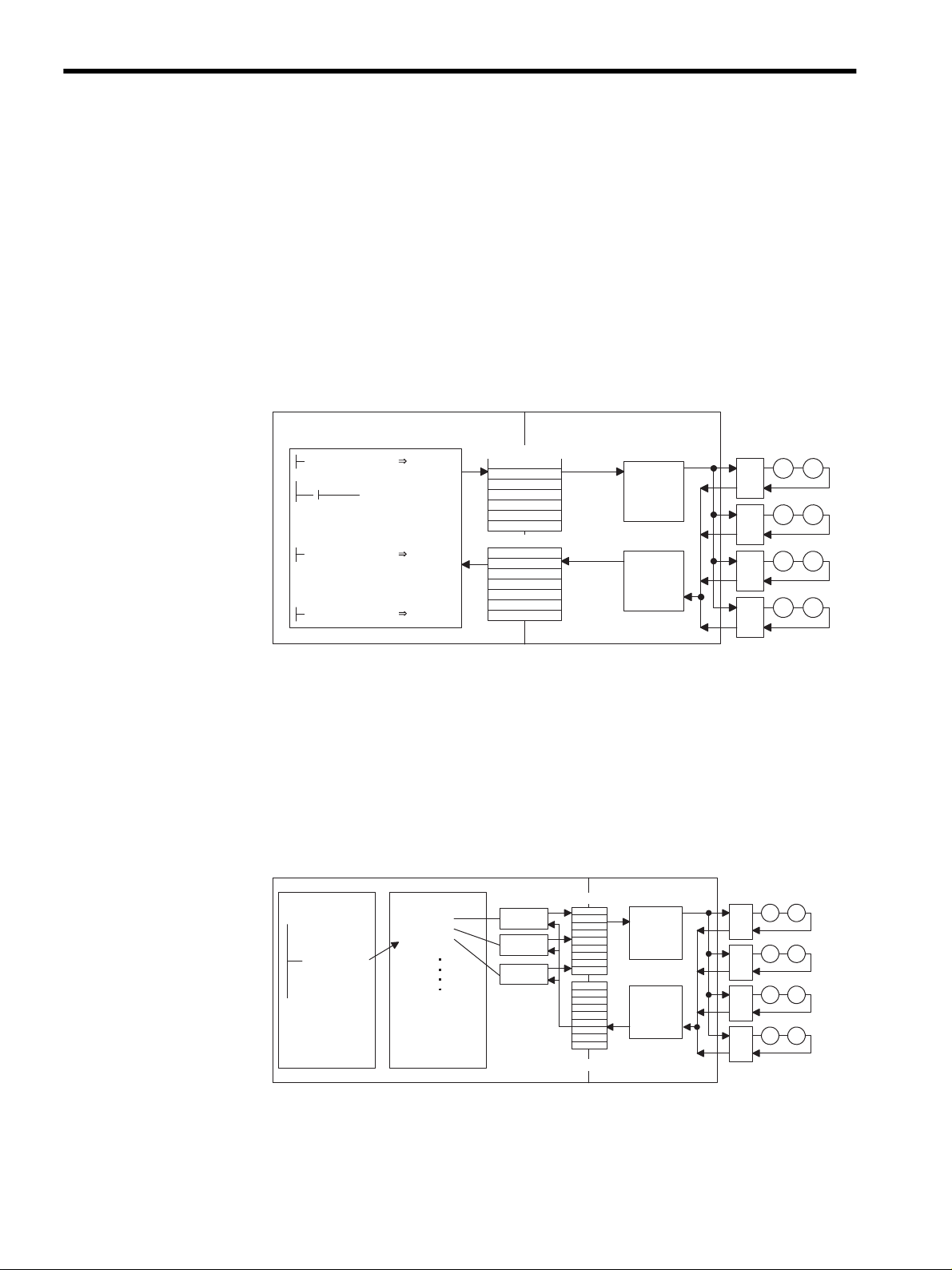
An electronic cam control loop can be configured using phase control. With normal phase
control, the position reference is generated by integrating the reference speed reference into
the SVA Module (see Fig. 2.8).
An electronic cam control loop cuts the integral circuit of the reference speed reference, and
provides the position reference from the phase compensation settings (see Fig. 2.9).
The following illustration shows a block diagram of a phase control loop.
CPU Module
Standard
speed
reference
setting
Position
compensation
NREF
OWCO15
To other
machine
PHBIAS
OLCO16
SVA Module
+
Integration
+
±
+
setting
Fig. 2.8 Block Diagram of Phase Control Loop
CPU Module
One scan change
calculation
Position reference
generation
×
θ
θ
S
Position
reference
NREF
OWCO15
PHBIAS
OLCO16
SVA Module
Integra-
+
tion
When Phase Reference Generation Operation Disable
(bit 7 of OWC000) turns ON, the integral circuit is cut.
Fig. 2.9 Block Diagram of Electronic Cam Control Loop
PI
ε
-
APOS
IL08
±
PI
ε
-
+
APOS
IL08
D/A
Counter
D/A
Counter
Servo driver
Speed
control
Servo driver
Speed
control
M
PG
M
PG
The electronic cam control loop is processed in the SVA Module. Therefore, the user can
easily control the electronic cam simply by selecting the phase control mode on the CPU
Module and providing the required parameters for the SVA Module.
2-20
Page 47

Ladder Logic Program Example
2.2 Control Modes
H0188
K1 TsH
MW00040×S
10000
PREPARE
MB010010
PHASE REFERENCE
ML03030
FGN
W00004
K2
÷
MW00041
DISPLACEMENT PATTERN
MA03050
RUNMOD
OWC000
KS
ML03010
FFGAIN
MW03012
RUN
OBC0010
DISPLACEMENT X
ML03020
Set the phase control mode to ON.
Set Phase Reference Generation Operation
Disable to ON.
Calculate the speed scalling constant (ks).
High-speed scan setting: SW0004
NR × FBppr × n
NR = Rated speed
FBppr = Number of feedback pulses
n = Number of pulse multipliers (1, 2 or 4)
* Reduce the fraction to the lowest terms
so that it can be stored as one word.
Feed forward gain [10000/100%]
Drive RUN command (RUN)
When MB01010 turns ON, phase control
starts.
The phase reference displacement [pulse] is
read from the FGN function.
Displacement X
The FGN pattern is set in advance.
60 × 10
4
Numerator* MW00040
Denominator* MW00041
Position
reference
2
DISPLACEMENT X
ML03020
00000
RUN command
MB010020
CHANGE
[
ML03022
Position BIAS
[[[
ML03022] + +MW03020
DISPLACEMENT X
ML03020
DEND
PREVIOUS VALUE
-ML03024
FFGAIN
] ×
MW03012
KS
÷
ML03010
DISPLACEMENT X
CHANGE
ML03022
NREF
OWC015
] ]
PHBIAS
OLC016
PREVIOUS VALUE
ML03024
Changes [pulses] per scan
When RUN command MB010020 turns ON,
the machine operates at the reference speed
NREF. When MB010020 turns OFF, the reference speed NREF remains at "0."
Standard speed reference setting [0.01%]
Phase compensation setting [pulse]
Phase reference previous displacement value
[pulse]
Fig. 2.10 RUN Command (DWG H04)
The example in the above illustration has been greatly simplified. In actual operation, each
register can be controlled from the user program.
2-21
Page 48

2 Motion Control
2.2.5 Zero Point Return Mode
2.2.5 Zero Point Return Mode
Overview
The zero point return operation returns the machine to the machine-specific zero point.
When an incremental encoder is used, the system zero point position data is destroyed if the
power supply is disconnected. Therefore, after turning ON the power, the system zero point
must be repositioned. As a general rule, a pulse generator (PG) with a zero point pulse and a
limit switch showing the zero point area are used to determine the zero point.
There are two zero point return methods. One method uses motion commands, and the other
method uses the zero point return mode. Care is required because zero point return opera-
tions are different with these two methods.
Using the zero point return mode is explained below.
Note: To use motion commands, see 2.4.4 Zero Point Return (ZRET).
When an absolute encoder is used, position reference “0” will be the position control when
zero point return is selected.
Details
Use the following procedure to perform operation in the zero return mode.
1. Set the motion fixed parameters.
2. Set the motion setting parameters.
3.
Set the zero point return mode (ZRN) to ON.
4.
Set the RUN command (RUN) to ON.
The axis is moved at approach speed in
the zero point direction.
a) When LSDEC turns ON, the axis is
decelerated to creep speed.
b)
LSDEC turns from ON to OFF, and
decelerates to a stop after detecting the
initial zero point pulse (Phase-C pulse).
c)
After decelerating to a stop, the axis is
moved only the zero point overtravel
distance, and stops at the zero point position.
d) The zero point return completion
signal (ZRNC) turns ON.
5.
Set the zero point return mode to OFF.
: System execution
: User settings
ZRN
RUN
Speed
/DECLS (limit switch)
External signal
LSDEC
(Deceleration point limit switch signal)
Phase-C pulse
(Zero point pulse)
Aφ , Bφ
Pulse after multiplication
ZRNC
* 1. If the machine is in Area B after the power is turned ON, a return can-
not be performed correctly. Be sure to move the machine back to Area
A before performing a return.
* 2. The limit switch (/DECLS) width must be at least twice that of the
high-speed scan setting.
Zero point return direction (ZRNDIR)
Specified direction
3.
4.
Approach
speed
4.
Time
8.
Area A Area B
Distance
Creep
speed
5.
7.
Limit switch width ≥ 2 × Ts
(Ts: High-speed scan setting)
Positioning completion range
*1
6.
*2
Zero point overtravel distance
2-22
Page 49

2.2 Control Modes
1. Set the motion fixed parameters according to the user’s machine.
Table 2.7 Examples of Fixed Parameters
No. Name Setting Range Meaning Setting
Example
7 Rated Motor Speed Setting 1 to 32000 Rated motor speed
8 Number of Feedback Pulses per
Motor Rotation
9 D/A Output Voltage at 100%
Speed
Feedback Pulses per Motor
Rotation (For high-resolution)
10 D/A Output Voltage at 100%
Torque Limit
* 1. Valid only with an SVB-01A Module.
* 2. Valid only with an SVA-02A Module.
*2
4 to 65532 Number of pulses
before multiplication
0.001 to 10.000 0.001 = 0.001 V
1 = 1 V
4 to 2147483647 1 = 1 pulse/rev 2048 pulses/
*1
0.001 to 10.000 0.001 = 0.001 V
1 = 1 V
3000 min
2048
6.000 V
rev
3.000 V
2. Set the motion parameters.
The following three methods can be used to set the motion setting parameters.
-1
2
• Using the MPE720 Setting Parameter Window
• Using a ladder logic program
• Using a motion program
Name Register No. Setting
Positive Torque Limit
Setting (TLIMP)*
Positive Speed Limiter Setting (NLIMP)
Negative Speed Limiter Setting (NLIMN)
Zero Point Offset
(ABSOFF)
Approach Speed
Setting (NAPR)
Creep Speed Setting
(NCLP)
Linear Acceleration
Time Constant
(NACC)
Linear Deceleration
Time Constant
(NDEC)
Positioning Completed Range Setting
(PEXT)
Error Count Alarm
Detection Setting
(EOV)
Table 2.8 Examples of Setting Parameters
Meaning Setting
Range
OW02 -327.68 to
327.67
OW04 0.00 to
327.67
OW05 0.00 to
327.67
OW06
OW0A 0 to 32767 Value (%) for rated speed: 1
OW0B 0 to 32767 Value (%) for rated speed: 1
OW0C 0 to 32767 Linear acceleration time con-
OW0D 0 to 32767 Linear deceleration time
OW0E 0 to 65535 1 = 1 reference unit
OW0F 0 to 65535 1 = 1 reference unit
31
-2
to 231-1
0.01 = 0.01%
1 = 1%
0.01 = 0.01%
1 = 1%
0.01 = 0.01%
1 = 1%
1 = 1 reference unit
With pulse: 1 = 1 pulse
= 0.01%
= 0.01%
stant (ms) at speed pattern
generation
constant (ms) at speed pattern generation
With pulse: 1 = 1 pulse
With pulse: 1 = 1 pulse
Example
-100.00
(-100.00%)
130.00
(130.00%)
130.00
(130.00%)
100 pulses
2000
(20.00%)
1000
(10.00%)
1000
(1 second)
1000
(1 second)
10 pulses
65535 pulses
2-23
Page 50

2 Motion Control
2.2.5 Zero Point Return Mode
Table 2.8 Examples of Setting Parameters (cont’d)
IMPORTANT
Name Register No. Setting
Position Loop Gain
Setting (KP)
Filter Time Constant
(NNUM)
* Valid only with an SVA-02A Module.
Range
OW10 0.0 to 3276.7 0.1 = 0.1 /s
1 = 1 /s
OW14 0 to 255 For simple S-curved
acceleration
Meaning Setting
Example
30.0
(30.0 /s)
0
In the example, the SERVOPACK is used as axis 1 of Module No. 1. When the Module
number and the axis number are different, see 4.1.2 Modules and Motion Parameter
Registers, and change the register number.
3. Set the Zero Point Return Mode (ZRN) to ON (bit 4 of OW00).
4. To start operation, set the RUN Servo ON (RUN) to ON (bit 0 of OW01).
The axis will be moved in the direction specified by the Zero Point Return Direction
Selection ZRNDIR (bit 9 of OW00).
a) When the Zero Point Return Deceleration Point Limit Switch LSDEC (bit 15 of
OW01) turns ON, the axis is decelerated to creep speed.
A user program must be created to connect the Limit Switch Signal DECLS (the DI signal included in
the LIO-01 Module) to the Zero Point Return Deceleration Point Limit Switch LSDEC (bit 15 of
OW01).
b) When LSDEC turns from ON to OFF, the point detected by the initial zero point
pulse (Phase-C pulse) is the zero point position. The axis is decelerated to a stop after
detecting the initial zero point pulse.
c) After decelerating to a stop, the axis is moved only the zero point overtravel distance
at creep speed in the zero point position direction and stops at the zero point position.
A zero point position offset value can also be set. (If Machine Coordinate System
Zero Point Position Offset OL06 is set in advance to 100, the position data will
be 100.)
d) The zero point return operation is completed when the axis enters the positioning
completed range. When the zero point return operation is completed, the Zero Point
Return Completed Signal ZRNC (bit 15 of IW00) turns ON.
5. After checking that the zero point return completion signal (ZRNC) is turned ON, set
the RUN command (RUN) and the zero return mode (ZRN) to OFF.
2-24
Page 51

User Program Example
H0110
RUNMOD
OWC0C0
Set the zero point return mode to ON.
IB00100: Limit switch signal (DECLS)
Driver RUN command (RUN)
When IB00110 turns ON, the zero point
return operation starts. When the zero
point return operation is completed, the
zero point return completion signal
IBC0C0F (ZRNC) turns ON.
LSDEC
OBC0C1F
IB00100
RUN
OBC0C10
RUNPB
IB00110
DEND
Example of RUN Operation
Speed
(%)
NR
(100%)
2.2 Control Modes
Napr
Nclp
0
NACC NDEC
Approach speed
Creep speed
Time (t)
Fig. 2.11 Zero Point Return Pattern
Operating Conditions
Input a limit switch signal width at least twice that of the high-speed scan setting.
Ladder Logic Program Example
2
Fig. 2.12 RUN Commands (DWG H01)
The example in the above illustration has been greatly simplified. In actual operation, each
register can be controlled from the user program.
2-25
Page 52

2 Motion Control
2.3.1 Prerequisites for Position Control
2.3 Position Control
This section describes the prerequisites for position control, and position control without using
motion commands.
2.3.1 Prerequisites for Position Control
With position control, the axis is moved to the target position, stops there, and holds that
position (servo clamp).
An incremental encoder or a Yaskawa absolute encoder is used as the position detector.
When a Yaskawa absolute encoder is used, the absolute position is stored, even when the
power for the machine (positioning device) is disconnected. Therefore, when the power is
turned ON again, the zero point return operation is not required.
There are two position control methods. One method uses motion commands (OW20),
and the other method does not use motion commands.
IMPORTANT
Whether or not motion commands (OW20) are to be used is set in the motion parame-
ters shown in the following table.
Motion Parameter Motion Command
(OW20) Not
Used
Motion fixed parameter No. 14
Bit 7 of Additional Function Selections
(Motion Command Code Selection)
Motion setting parameter
Bit 8 of RUN Mode Settings (OW00)
(Motion Command Code Enable/Disable)
Note: When bit 7 (motion command code selection) of motion fixed param-
eter No. 14 (Additional Function Selections) is not selected for use
and bit 8 (motion command code enable/disable) of RUN Mode Settings (OW00) motion setting parameter is set to “1” (= enabled),
the axis is controlled without motion commands (OW20).
The position control mode is available with all Motion Modules. However, it can be used for the SVB-
01 and PO-01 Modules only when motion command code is enabled.
The following table shows position control mode availability for each Motion Module.
Motion
Module
SVA-01A Available Available
SVA-02A Available Available
SVB-01 Available Not available
PO-01 Available Not available
Motion Command Code
Enabled
Position Control Mode
0 (= Not used) 1 (= Used)
0 (= Disabled) 1 (= Enabled)
Motion Command Code
Disabled
Motion Command
(OW20) Used
2-26
Page 53

2.3 Position Control
IMPORTANT
When using a motion program, always set Position Reference Type (bit 14 of OW01) to 1 (incre-
mental addition mode).
The default is 1 (incremental addition mode).
Table 2.9 shows the differences when motion commands (OW20) are used, and when no
motion commands are used.
Table 2.9 Differences When Motion Commands are Used/Not Used
Item Motion Commands
(OW20) Not
Used
Reference Unit Pulse Pulse, mm, inch, or
Electronic Gear Function Not possible Possible
Finite length position control Possible Possible
Infinite length position control that rotates
the axis in one direction only, without resetting after one rotation
Infinite length position control that resets
the axis after one rotation
Position reference Absolute position
Position buffer Not possible Possible
Position monitor Pulse unit Reference unit
Speed reference Percentage (%) refer-
Possible Possible
Not possible Possible
mode
ence
Motion Commands
(OW20) Used
deg can be selected.
Absolute position
mode or incremental
addition mode can be
selected.
The percentage (%)
reference or the reference unit can be
selected.
2
The meaning of the terms used in the above table and their method of application are
described below.
2-27
Page 54

2 Motion Control
2.3.1 Prerequisites for Position Control
Reference Unit
The reference units input to the Module are set with the following motion fixed parameter
settings.
Pulses, millimeters, degrees, or inches can be used as the reference unit. The reference unit
is specified in bits 0 to 3 of motion fixed parameter No. 17 (Motion Controller Function
Selection Flags).
The minimum reference unit that can be specified in the Module is determined by the above
unit settings and the setting of motion fixed parameter No. 18 (Number of Digits Below
Decimal Point).
When motion commands (OW20) are not used, the unit will be the pulse.
Table 2.10 Minimum Reference Unit (1 Reference Unit)
Number of Digits
Below Decimal
Point
0 1 pulse 1 mm 1 deg 1 inch
1 1 pulse 0.1 mm 0.1 deg 0.1 inch
2 1 pulse 0.01 mm 0.01 deg 0.01 inch
3 1 pulse 0.001 mm 0.001 deg 0.001 inch
4 1 pulse 0.0001 mm 0.0001 deg 0.0001 inch
5 1 pulse 0.00001 mm 0.00001 deg 0.00001 inch
Note: The number of digits below the decimal point is specified in motion
fixed parameter No. 18 (Number of Digits Below Decimal Point).
Bits 0 to 3 of Motion Controller Function Selection Flags
Pulse (= 0) mm (= 1) deg (= 2) inch (= 3)
Motion Fixed Parameter No. 17
2-28
Page 55

2.3 Position Control
Electronic Gear
In contrast to the reference unit input to the Module, the mechanical travel unit is called the
“output unit.”
The electronic gear converts position or speed units from reference units (millimeters,
degrees, or inches) to output units (millimeters, degrees, or inches).
When the axis at the motor has rotated m times and the mechanical configuration allows the
axis at the load to rotate n times, this electronic gear function can be used to make the refer-
ence unit equal to the output unit.
The electronic gear function is set in the motion setting parameters shown in Table 2.11.
Table 2.11 Electronic Gear Parameters
Motion Fixed Parameter Name and Meaning
No. 17
Bit 4 of Motion Controller
Function Selection Flags
No. 19 Travel distance per machine rotation
No. 21 Motor side gear ratio
No. 22 Machine side gear ratio
Electronic gear selection (0: Disabled, 1: Enabled)
• Disabled when the unit selected is the pulse. Set
Disabled = (0).
• This parameter setting is invalid when Disabled =
(0) is set for the electronic gear selection.
• This parameter setting is invalid when Disabled =
(0) is set for the electronic gear selection.
• This parameter setting is invalid when Disabled =
(0) is set for the electronic gear selection.
2
When the unit selected is the pulse and motion commands (OW20) are not used, the
electronic gear function is disabled.
2-29
Page 56

2 Motion Control
2.3.1 Prerequisites for Position Control
Table 2.12 shows the meanings of the above parameters and gives some setting examples.
Table 2.12 Electronic Gear Parameters and Constant Table
Servo Fixed
Name Description Initial
Parameter No.
No.19 Travel Distance
Per Machine
Rotation
• This parameter shows the load travel distance for each rotation of the load
axis. Sets the load travel distance value divided by the minimum reference
unit.
No.19 =
Load travel distance per load axis rotation
Minimum reference unit
• Some examples of the load travel distance are shown below.
Travel Distance Per
Load Configuration Examples
Machine Rotation
P [mm] Ball
screw
P
P = Ball screw pitch
360 [° ] Round
table
One rotation = 360°
πD [mm] Belt
π
D
Value
10000
D
• No.19 setting range: 1 to 231-1[1 = 1 reference unit]
Setting Examples
• Load travel distance per load axis rotation = 12 mm
• Minimum reference unit = 0.001 mm [reference unit: mm, digit number
after decimal point: 3]
No.19 = = 12000
12 mm
0.001 mm
2-30
Page 57

Table 2.12 Electronic Gear Parameters and Constant Table (cont’d)
2.3 Position Control
Servo Fixed
Parameter No.
No.21
No.22
Name Description Initial
Servomotor Gear
Ratio
Machine Gear
Ratio
• These parameters are used to set the gear ratio between the motor and the
load. When the motor axis has rotated m times and the mechanical configuration allows the load axis to rotate n times, set the following
values: No.21 = m rotations
No.22 = n rotations
• Setting range: 1 to 65,535 [rotations]
Setting Examples
n
m
4 rotations
Load axis n rotations
9 rotations
37494
21
No. 22 = 4
7 rotations
Motor axis
m rotations
3 rotations
Gear ratio = = × =
Therefore, set the following values: No. 21 = 21
Val ue
1
1
2
Electronic Gear Parameter Setting Example (A): With Ball Screw
7 rotations
Motor
In the above machine system, if the requirement is reference unit = output unit = 0.001 mm,
the setting of each parameter will be as follows:
•
No.19 = = 6000
•
Gear ratio = =
• No.21 = 7
• No.22 = 5
m
6 mm
0.001 mm
m
5 rotations
n
n
Ball screw pitch
P = 6 mm/rotation
5
7
2-31
Page 58

2 Motion Control
2.3.1 Prerequisites for Position Control
Electronic Gear Parameter Setting Example (B): Rotating Load
Motor
m
30 rotations
10 rotations
n
Rotating load
360°/rotation
In the above machine system, if the requirement is reference unit = output unit = 0.1°, the
setting of each parameter will be as follows:
•
No.19 = = 3600
•
Gear ratio = = =
360°
0.1°
n
10301
m
3
• No.21 = 3
• No.22 = 1
Axis Selection
There are two types of position control: Finite length position control, where return and
other operations are performed only within a specified range, i.e., within a prescribed posi-
tioning interval, and infinite length position control, which is used for rotation in one direc-
tion only.
There are two infinite length position control methods. One method involves resetting the
conveyor belt or other device to “0” after one rotation; the other method involves rotating
the conveyor belt in one direction only, without resetting after one rotation.
Axis selection involves selecting which of these types of position control is to be used. The
axis selection is set in bit 5 of motion fixed parameter No. 17 (Motion Controller Function
Selection Flags).
When motion commands (OW20) are not used, axis selection is disabled. (Set as a finite
length axis (= 0).)
Table 2.13 Axis Selections
Types of Position Control Axis Selection
Finite length position control Finite length axis
(= 0)
Infinite length position control that rotates the axis in
one direction only, without resetting after one rotation
Infinite length position control that resets the axis after
one rotation*
* The reset position is set in motion fixed parameter No. 23 (Infinite
Length Axis Reset Position).
Finite length axis
(= 0)
Infinite length axis
(= 1)
2-32
Page 59

2.3 Position Control
Position Reference
There are two methods of setting the position reference: Direct designation, which directly
sets the position reference in OL12, and indirect designation, which specifies the num-
ber of the position buffer from which the position reference is stored in OL12.
There are two direct designation methods: The absolute position reference mode, in which
the absolute position is set in OL12, and the incremental addition mode, in which the
present travel distance is added to the previous position reference value (previous value of
OL12).
Table 2.14 shows the parameters relating to the position reference.
Table 2.14 Position Reference Parameters
Parameter Type Parameter No.
(Register No.)
Motion Setting
Parameters
* 1. This parameter is invalid when the position reference value selection is the position buffer
(indirect designation).
* 2. The setting data differs according to the setting of the Position Reference Value Selection (bit
12 of OW01) and the Position Reference Type (bit 14 of OW01).
Bit 12 of
01
OW
Bit 14 of
OW01
OL12
Name Description Initial
Position Reference
Value Selection
Position Reference
Type
Position Reference
Setting
Sets the position reference designation method.
• 0: Direct designation
Directly sets the position data in OL
Specifies in bit 14 of OW
position data is to be set in the absolute position mode or the incremental addition mode.
• 1: Indirect designation
Sets the number of the position buffer in
12. The absolute position must first be
OL
stored in the specified position buffer.
Specifies the type of position data.
• 0: Absolute position mode
Sets the absolute position in OL
• 1: Incremental addition mode
Adds the present travel distance value to the
previous value of OL
*1
result in OL
Sets the position data.
12.
*2
2
Val ue
0
12.
01 whether the
1
12.
12 and sets the
0
IMPORTANT
When indirect designation is used to specify the position buffer number, the positions stored in the
position buffer are treated as absolute positions.
When a motion command (OW20) is not used, the position reference value set in OL12 is
treated as an absolute position.
2-33
Page 60

2 Motion Control
1234
1
2
3
4
99
256
Position buffer
99
OL12
Position buffer number
(1 to 256)
1234 of position buffer
99 is used as the absolute position.
2.3.1 Prerequisites for Position Control
Table 2.15 Position Reference Value Selection
Position Reference
Value Selection
(Bit 12 of OW01)
0
(Direct designation)
Position Reference
Type
(Bit 14 of OW01)
0
(Absolute position
mode)
1
(Incremental addition
mode)
1
(Indirect designation)0(Absolute position
mode)
Position Reference (OL12)
Sets the absolute position. (Moves to the setting position.)
Example: OL12 ← 10000
OL12 ← 20000
Sets the present travel distance value (increment) added to the previous value of OL12.
OL12 ← Previous OL12 + Incremental travel distance
Example: When the previous OL12 = 1,000 and the present
travel distance is 500, then: OL12 ← 1000 + 500 = 1500
Sets the position buffer number.
The absolute position must be stored in advance in the position
buffer with the specified number.
With the position reference for an infinite length axis, the present travel distance (incremen-
tal travel distance) is added to the previous position reference (OL12), and the position
reference (OL12) is reset. The position reference (OL12) must not be set in the
range of 0 to (infinite length axis reset position − 1).
Position Buffers
The position buffers are a collection of position data stored in the SVA Module, and a maxi-
mum of 256 points can be stored for each axis. They are used for the position data when
POSITIONING and other motion commands are executed. Continuous operation is enabled
by storing the position data in advance, and by using a simple program that only specifies
the points.
2-34
Page 61

CPU Module SVA Module
Axis 1 position buffers
OW01 RUN Command Settings
OL12
OW21
OL38
OL3A
Position Reference Setting
Motion Control Flags
Position Buffer Access Number
Position Buffer Write Data
256
1
2
3
Axis 2
1
2
3
256
2.3 Position Control
Axis 3
1
Axis 4
2
1
3
2
3
INFO
IL28
Position Buffer Read Data
256
256
With the SVA-02A Module (2-axis Servo Module), there are position buffers for only 2 axes.
Using the Position Buffers
By first storing in the position buffers the position information for a machine whose operat-
ing pattern has been determined in advance, continuous positioning of up to 256 points is
enabled simply by refreshing the buffer pointer at the completion of a single-block opera-
tion.
Writing to Position Buffers
CPU Module
OW21
OL38
OL3A
96
123456
SVA Module
Axis 1 position buffers
1
2
3
123456
96
Axis 2
1
2
3
Axis 3
1
2
3
Axis 4
1
2
3
2
256
256
256
256
1. Set the Position Buffer Access Number (OL38). Any number between 1 and 256
can be set.
2. Set the Position Buffer Write Data (OL3A).
3. Set Position Buffer Write (OB21E) in the Motion Command Control Flags to ON.
2-35
Page 62

2 Motion Control
2.3.1 Prerequisites for Position Control
Reading Position Buffers
CPU Module SVA Module
OW21
OL38
IL28
93
543210
Axis 1 position buffers
1
2
3
543210
93
93
256
Axis 2
1
2
3
256
Axis 3
1
2
3
256
Axis 4
1
2
3
256
1. Set the Position Buffer Access Number (OL38). Any number between 1 and 256
can be set.
INFO
IMPORTANT
2. Set Position Buffer Read (OB21F) in the Motion Command Control Flags to ON.
3. After two scans, the position data specified in Position Buffer Read Data (IL28)
will be stored.
1. Position buffers can be used only when motion commands are used in the position control mode.
2. The position data specified in the position buffers are absolute position references.
The data in the position buffers is deleted by turning OFF the power and resetting the CPU Module
Master. Be sure to set the data when the power is turned ON, or before using the position buffers.
Using the Position Buffers as Position References
Position buffers
12345
OW01
OL12
OB01C
1
Position buffer number
This value will be
the position
reference.
1. Set bit 12 of the RUN Command Settings (OW01) to ON.
2. Set a position buffer number 1 to 256 in place of the position reference in the Position
Reference Setting (OL12).
2-36
Page 63

2.3 Position Control
In this way, the data for the position buffer number specified in OL12 functions as the
position reference.
Position Monitoring
Table 2.16 shows the parameters used to monitor positioning.
Table 2.16 Position Monitoring Parameters
Motion Monitoring
Parameter No.
(Register No.)
IL02 Calculated Position in
the Machine Coordinate
System
IL08 Machine Coordinate
System Feedback
Position (APOS)
IL18 Machine Coordinate
System Reference
Position (MPOS)
IL2E Calculated Reference
Coordinate System
Position (POS)
Name Description
*1
(CPOS)
The calculated position of the machine coordinate system managed by the SVA Module is
reported. Normally, the position data reported
in this parameter will be the target position for
each scan.
The feedback position of the machine coordi-
nate system is reported.
The position output externally by the SVA
Module and the reference position of the
machine coordinate system are reported.
In machine lock status, this data is not
refreshed. (With the machine lock status, the
data is not output externally.)
When the machine lock function is not used,
this position is the same as that in IL02.
This position is significant when the axis
selected is an infinite length axis.
With an infinite length axis, the target position
for each scan corresponding to the position ref-
erence in this parameter is reported.
*2
*3
*4
2
* 1. The machine coordinate system is the basic coordinate system that is
set according to the zero return mode execution, the Zero Point Return
(ZRET) motion command execution, or the Zero Point Setting
(ZSET) motion command operation. The SVA Module manages the
positions using this machine coordinate system.
* 2. When an infinite length axis is selected, a range of 0 to (infinite length
axis reset position − 1) is reported.
With the position reference for an infinite length axis, the present
travel distance (incremental travel distance) is added to the previous
position reference (OL12), and reset as the position reference
(OL12).
The position reference (OL12) must not be set in the range of 0 to
(infinite length axis reset position − 1).
* 3. When an infinite length axis is selected, a range of 0 to (infinite length
axis reset position − 1) is reported.
* 4. With a finite length axis, this position is the same as that in IL02.
2-37
Page 64

2 Motion Control
2.3.1 Prerequisites for Position Control
Speed Reference
There are two methods of setting the speed reference. One method involves using a refer-
ence unit for the speed reference setting, such as the rapid traverse speed, approach speed, or
creep speed. The other method involves setting the percentage (%) corresponding to the
rated speed.
Table 2.17 shows the parameters relating to the speed reference.
Table 2.17 Speed Reference Parameters
Parameter Type Parameter No.
(Register No.)
Motion Fixed
Parameters
Motion Setting
Parameters
No.5 Pulse Counting Mode
No.7 Rated Motor Speed Setting Sets the number of rotations when the motor is
No.8 Number of Feedback Pulses
Bit 13 of
OW01
OW0A Approach Speed Setting Sets the zero point return (ZRET) approach
OW0B Creep Speed Setting Sets the zero point return (ZRET) creep speed.
OW15 Speed Reference Setting This setting is valid when the Speed Reference
OL22 Rapid Traverse Speed This speed is valid when the Speed Reference
OW2C Override Changes the actual rapid traverse speed.
Name Description
Selection
Per Rotation
Speed Reference Value
Selection
Sets the pulse count mode and multiplier.
0: Sign mode, ×1
1: Sign mode, ×2
2: Up/Down mode, ×1
3: Up/Down mode, ×2
4: A/B mode, ×1
5: A/B mode, ×2
6: A/B mode, ×4
rotated at the rated speed (100% speed).
Sets the number of pulses (the value before multiplication) per motor rotation.
Specifies the setting unit for the rapid traverse
speed, approach speed, and creep speed, and
specifies the register number for the rapid
traverse speed.
0: Specifies the speed using a reference unit, and
sets the Rapid Traverse Speed in OL22.
1: Specifies the speed using the percentage (%)
corresponding to the rated speed, and sets the
Rapid Traverse Speed in OW15.
speed.
The unit varies according to the Speed Reference
Selection (bit 13 of OW01).
The unit varies according to the Speed Reference
Selection (bit 13 of OW01).
Selection (bit 13 of OW01) is “1.”
Sets the percentage (1 = 0.01%) corresponding
to the rated speed as the rapid traverse speed.
Selection (bit 13 of OW01) is “0.” Set the
rapid traverse speed using the reference unit.
2-38
Page 65

2.3 Position Control
When Motion Commands Are Not Used
When motion commands are not used, the Speed Reference Selection Flags are disabled,
and the speed-related parameters have the meanings shown in the following table.
Parameter No. Name Description
Bit 3 of OW01 Speed Reference Value
Selection
OW0A Approach Speed Setting Specified as a percentage (%) of the rated
OW0B Creep Speed Setting Specified as a percentage (%) of the rated
OW15 Speed Reference Setting The rapid traverse speed is specified as a per-
OL22 Rapid Traverse Speed Invalid
OW2C Override Invalid
Invalid
speed.
speed.
centage (%) of the rated speed.
When Motion Commands Are Used
2
When motion commands are used, the meanings of the speed-related parameters differ
according to the Speed Reference Selection (bit 13 of OW01).
Bit 13 of
OW01
0 OW0A Approach Speed Setting Specified using the reference unit.
1 OW0A Approach Speed Setting Specified as a percentage (%) of the
Parameter
No.
OW0B Creep Speed Setting Specified using the reference unit.
OW15 Speed Reference Setting Invalid
OL22 Rapid Traverse Speed Specified using the reference unit.
OW2C Override Valid
OW0B Creep Speed Setting Specified as a percentage (%) of the
OW15 Speed Reference Setting The rapid traverse speed is specified
OL22 Rapid Traverse Speed Invalid
OW2C Override Valid
Name Description
rated speed.
rated speed.
as a percentage (%) of the rated
speed.
2-39
Page 66

2 Motion Control
2.3.1 Prerequisites for Position Control
Table 2.18 shows some examples of the parameter settings.
Table 2.18 Parameter Setting Examples
Parameter Type Parameter No.
(Register No.)
Motion Fixed
Parameters
Motion Setting
Parameters
* 1. Select Enabled (= 1) in bit 9 (override selection) of motion fixed parameter No. 17.
* 2. “4” is the pulse multiplier.
No.5 Pulse Counting Mode
Selection
No.7 Rated Motor Speed
Setting
No.8 Number of Feedback
Pulses Per Rotation
Bit 13 of
OW01
OW0A Approach Speed Setting
OW0B Creep Speed Setting
OW15 Speed Reference Setting
OL22 Rapid Traverse Speed
OW2C
Speed Reference Value
Selection
Override
Name Description Initial Value
No. 5 = A/B mode, × 4
No. 7 = 3,000 min
No. 8 = 2,048 p/r
Therefore,
Rated speed = 3,000 min
= 3,000 ×2,048 ×4
= 2,575,000 ppm
Various parameter setting
examples are given below.
*1
Parameter Setting Examples
1. Speed Reference Value Selection Set to “0”
A/B mode (×4)
-1
3000
-1
*2
2048
0
0
0
0
0
100%
a) Pulses Selected as the Unit
When you wish to perform operations with the fixed parameters set for a rapid
traverse speed of 1,500 min
150 min
-1
, use the following settings.
• OW0A = 30 (min
• OW0B = 150 (min
• OW15 =
−
• OL22 = 1,500 (min
-1
, an approach speed of 300 min-1, and a creep speed of
-1
) × 2,048 × 4 (ppr) ÷ 1,000 = 2,457 (= 2,457,000 ppm)
-1
) × 2,048 × 4 (ppr) ÷ 1,000 = 1,228 (= 1,228,000 ppm)
(Invalid)
-1
) × 2,048 × 4 (ppr) ÷ 1,000 = 12,288 (= 12,288,000
ppm)
• OW2C = 10,000 (100%)
b) Millimeters Selected as the Unit
When you wish to perform operations with the fixed parameters set for a rapid
traverse speed of 900 mm/min, an approach speed of 180 mm/min, and a creep speed
of 90 mm/min in a machine configuration that moves the axis 10 mm in one rotation,
use the following settings.
• OW0A = 180
• OW0B = 90
−
• OW15 =
(Invalid)
• OL22 = 900
2-40
Page 67

2.3 Position Control
OW15 = × 10,000 = 5,000 (50.00%)
1,500 (min-1)
3,000 (min
-1
)
• OW2C = 10,000 (100%)
2. Speed Reference Value Selection Set to “1”
a) When you wish perform operations with the fixed parameters set for a rapid traverse
speed of 1,500 min
-1
min
, use the following settings.
-1
, an approach speed of 300 min-1, and a creep speed of 150
•
OW0A = × 10,000 = 1,000 (10.00%)
•
OW0B = × 10,000 = 500 (5.00%)
300 (min-1)
3,000 (min
150 (min-1)
3,000 (min
-1
)
-1
)
•
−
• OW22 =
(Invalid)
• OW0A = 10,000 (100%)
b) When you wish to leave the above speed reference settings unchanged, but halve the
operating speed, use the following setting.
• OW2C = 5,000 (50.00%)
2.3.2 Position Control Without Using Motion Commands
Overview
Position control performs speed acceleration/deceleration according to the related parame-
ters, and positions the axis to the target position of the position reference setting parameter
(OL12).
2
IMPORTANT
Position control without using motion commands is not valid for the SVB-01 and PO-01 Modules. For
these Modules, always enable motion commands.
2-41
Page 68

2 Motion Control
2.3.2 Position Control Without Using Motion Commands
Details
Use the following procedure to perform position control operations without using motion
commands.
1. Set the motion fixed parameters.
2. Set the motion setting parameters.
Set the position control mode (PCON).
3.
4. Set the RUN command (RUN) to ON.
Positioning is started for the axis.
5. Set the position control mode to OFF.
Servo clamp status
PCON
RUN
Speed
(100%)
Linear acceleration
time constant
POSCONP
: System execution
: User settings
(%)
Steady travel
speed
Position
0
Time (t)
Linear deceleration time constant
Positioning completed range
1. Set the motion fixed parameters according to the user’s machine.
Table 2.19 Examples of Fixed Parameters
No. Name Setting Range Meaning Setting
Example
7 Rated Motor Speed Setting 1 to 32000 Rated motor speed
8 Number of Feedback Pulses per
Rotation
9 D/A Output Voltage at 100%
Speed
Number of Feedback Pulses per
4 to 65532 Number of pulses
before multiplication
0.001 to 10.000 0.001 = 0.001 V
1 = 1 V
4 to 2147483647 1 = 1 pulse/rev 2048 pulses/
Motor Rotation
(For high-resolution)
10 D/A Output Voltage at 100%
Torque Limit
*1
0.001 to 10.000 0.001 = 0.001 V
*2
1 = 1 V
3000 min
2048
6.000 V
rev
3.000 V
-1
* 1. Valid only with an SVB-01 Module.
* 2. Valid only with an SVA-02A Module.
2. Set the motion parameters to be used in position control mode.
The following three methods can be used to set the motion setting parameters.
• Using the MPE720 Setting Parameter Window
• Using a ladder logic program
• Using a motion program
2-42
Page 69

Table 2.20 Examples of Setting Parameters
2.3 Position Control
Name Register No. Setting
Positive Torque Limit
Setting (TLIMP)*
Positive Speed Limiter
Setting (NLIMP)
Negative Speed Limiter
Setting (NLIMN)
Machine Coordinate
System Zero Point Offset
Setting (ABSOFF)
Linear Acceleration Time
Constant (NACC)
Linear Deceleration Time
Constant (NDEC)
Positioning Completed
Range Setting (PEXT)
Error Count Alarm
Detection Setting (EOV)
Position Loop Gain Setting
(KP)
Filter Time Constant
(NNUM)
Feed Forward Gain
Setting (Kf)
Position Reference Setting
(XREF)
Speed Reference Setting
(NREF)
Meaning Setting
Range
OW02 -327.68 to
327.67
OW04 0.00 to
327.67
OW05 0.00 to
327.67
OL06
OW0C 0 to 32767 Linear acceleration time con-
OW0D 0 to 32767 Linear deceleration time
OW0E 0 to 65535 1 = 1 reference unit
OW0F 0 to 32767 1 = 1 reference unit
OW10 0.0 to 3276.7 0.1 = 0.1 /s
OW14 0 to 255 For simple S-curved acceler-
OW11 0 to 200 1 = 1% 0
OL12
OW15 -327.68 to
31
to 231-1
-2
31
to 231-1
-2
327.67
0.01 = 0.01%
1 = 1%
0.01 = 0.01%
1 = 1%
0.01 = 0.01%
1 = 1%
1 = 1 reference unit
With pulse: 1 = 1 pulse
stant (ms) at speed pattern
generation
constant (ms) at speed
pattern generation
With pulse: 1 = 1 pulse
With pulse: 1 = 1 pulse
1 = 1 /s
ation
1 = 1 reference unit
With pulse: 1 = 1 pulse
Speed reference value
0.01 = 0.01%
1 = 1%
Example
-100.00
(-100.00%)
130.00
(130.00%)
130.00
(130.00%)
100 pulses
1000
(1 second)
1000
(1 second)
10 pulses
65535 pulses
30.0
(30.0 /s)
0
10000 pulses
50.00 (50.00%)
2
* Valid only with an SVA-02A Module.
3. Select the Position Control Mode (PCON) (bit 2 of OW00).
4. To start operation, set the RUN Servo ON (RUN) to ON (bit 0 of OW
01).
The axis is positioned according to the specified motion parameters.
Even during positioning, the motion parameter settings can be changed.
5. To stop position control, set the RUN command (RUN) and the position control mode
(PCON) to OFF.
The POSCOMP Positioning Completed Signal (bit 13 of IW
00) turns ON when the
axis enters the positioning completed range. Control continues even when the axis
enters the positioning completed range (the axis enters servo clamp status).
2-43
Page 70

2 Motion Control
2.3.2 Position Control Without Using Motion Commands
User Program Example
Example of RUN Operation
Speed
(%)
NR
(100%)
NREF
0
Fig. 2.13 Position Pattern
Operating Conditions
Steady travel speed
reference
Position reference
NACC NDEC
Time (t)
In the pattern shown in the above illustration, the axis is stopped at an absolute position of
10000 (pulses).
• Position reference: XREF = 10000 (pulses)
Ladder Logic Program Example
H0004
0000010000
RUNPB
IB00304
DEND
RUNMOD
OWC080
XREF
OLC092
RUN
OBC0810
Fig. 2.14 RUN Commands (DWG H03)
The example in the above illustration has been greatly simplified. In actual operation, each
register can be controlled from the user program.
Set the position control mode to ON.
Position reference pulse (XREF)
(Absolute position: 10000)
Driver RUN command (RUN)
When IB00304 turns ON, position control
starts, and the axis is moved to absolute
position 10000. When absolute position
10000 is reached, the IBC080D positioning
completed signal turns ON.
2-44
Page 71

2.4 Position Control Using Motion Commands
Speed
(%)
(100%)
Time (t)
Rated speed
Linear acceleration time constant Linear deceleration time constant
Rapid
traverse
speed
Position
reference
2.4 Position Control Using Motion Commands
This section describes position control using motion commands.
2.4.1 Overview of Motion Commands
The following table lists the motion commands and gives an overview of each.
Command Name Description
1 Positioning (POSING) Positions the axis at the specified position using the specified acceleration/
deceleration time constant and speed.
2
2 External Positioning
(EX_POSING)
Latches a counter when a latch signal (external positioning signal) is input
during positioning (POSING), and positions the axis at a position where it
has traveled the external positioning travel distance from that position.
Speed
(%)
(100%)
0
Linear acceleration
time constant
Latch signal (external
positioning signal)
Rated speed
Rapid
traverse
speed
External
positioning
travel distance
Time (t)
Linear deceleration time constant
2-45
Page 72

2 Motion Control
0
POSCOMP
Speed
(%)
Position
Positioning completed range
Time (t)
2.4.1 Overview of Motion Commands
Command Name Description
3Zero Point Return
(ZRET)
Returns the system to the machine coordinate system zero point. Eight zero
return modes are provided.
4 Interpolation
(INTERPOLATE)
Reverse
direction
1. 2. 3. 4.
Rapid traverse
Speed
reference
Dog
(Deceleration limit switch)
speed
0
Zero point signal
(Phase-C pulse)
← →
Forward
direction
Approach
speed
Creep speed
Zero
point
Zero point return
position
Time
Zero point return final
travel distance
Performs interpolation feeding using the position data distributed from the
CPU Module.
5 Not used. This command is used by the system.
Do not use it in a user program.
6 Interpolation with
Position Detection
(LATCH)
Latches a counter when a latch signal is input during an interpolation feed
operation, and reports the changed latch position to the reference unit system.
Speed
(%)
0
Latch signal
Positioning completed range
POSCOMP
2-46
Reports this position.
(IL06)
Position
Time (t)
Page 73

2.4 Position Control Using Motion Commands
Command Name Description
7 Fixed Speed Feed
(FEED)
Performs rapid traverse in the infinite length direction at the specified speed
and acceleration time.
8 Fixed Length Feed
(STEP)
9 Zero Point Setting
(ZSET)
Speed
(%)
100%
Linear acceleration time constant Linear deceleration time constant
* The position is the speed reference integral value.
Rated speed
Rapid traverse
speed
Position*
0
NOP command
Time (t)
Performs STEP travel positioning using the specified direction, speed, and
acceleration time constant.
Speed
(%)
100%
0
Linear acceleration time constant Linear deceleration time constant
Rated speed
Rapid traverse
speed
STEP travel
distance
Time (t)
Determines the machine coordinate zero point, and validates the stroke limit
check.
2
2-47
Page 74

2 Motion Control
2.4.2 Positioning (POSING)
2.4.2 Positioning (POSING)
Overview
Positions the axis at the position reference position using the specified acceleration/deceler-
ation time constant and the specified rapid traverse speed.
The rapid traverse speed and the position reference value can be changed during operations.
When the change in the position reference value is less than the deceleration distance or the
reverse direction is used, the system first decelerates to a stop and then is repositioned
according to the position reference value.
Details
Use the following procedure to perform positioning operations.
1. Set the motion fixed parameters.
Set the motion setting parameter initial values.
2. Set the position control mode (PCON).
3. Set the motion setting parameters.
4. Set Servo ON (RUN) to ON.
5. Execute the positioning (POSING)
motion command.
Positioning started for the axis.
Positioning completed signal (POSCOMP)
turned ON.
: System execution
: User settings
PCON
RUN
Motion command
(POSING)
Speed
(%)
(100%)
0
Linear acceleration time constant
Positioning completed range
POSCONP
Rated speed
Rapid
traverse
speed
Position
Time (t)
Linear deceleration time constant
1. Set the initial values for the motion fixed parameters and the motion setting parameters
according to the user’s machine.
When performing position control using motion commands, be sure to set the following
parameters:
• Set “Use (= 1)” in bit 7 (motion command code selection) of motion fixed parameter
No. 14 (Additional Function Selections).
• Set “1 (= Enabled)” in bit 8 (motion command code enable/disable) in the RUN
Mode Settings (OW00) motion setting parameter.
2. Set the Position Control Mode (PCON) (bit 2 of OW00).
3. Set the motion setting parameters to be used in positioning (POSING).
2-48
Page 75

2.4 Position Control Using Motion Commands
YES
YES
YES
NO
NO
NO
YES
NO
POSING
Start condition check
Control mode
= position control mode?
Motion command status
Busy = OFF?
Return (OK)
Return (NG)
Return (NG)
Motion command code
= NOP||POSING||
ENDOF_INTERPOLATE?
Motion command response
= NOP||POSING||
INTERPOLATE
ENDOF_INTERPOLATE?
4. Set RUN Servo ON (RUN) to ON (bit 0 of OW01).
For the PO-01 Module, set Excitation ON (RUN) to ON.
5. Set positioning (POSING = 1) in the motion command code (OW20).
2
The specified motion parameters perform positioning for the axis. Even during position-
ing, the motion parameter settings can be changed.
The positioning command operations are as follows:
a) Operation Start
Servo ON (bit 0 of OW01).
Set the positioning (POSING = 1) to motion command code (OW20).
b) Feed Hold
Set Hold (bit 0 of OW21) to ON.
At feed hold completion, HOLDL (bit 1 of IW15) turns ON.
c) Feed Hold Release
Set Hold (bit 1 of OW21) to OFF. Positioning resumes.
d) Abort
Set Abort (bit 1 of OW21) to ON, or set NOP (= 0) in the motion command code.
Busy (bit 0 of IW15) turns ON during abort processing, and turns OFF at com-
pletion of the abort.
Note: When the abort has been completed and released (ABORT turns
OFF), the following occurs:
• When the Position Reference Type (bit 14 of OW01) is the absolute position
mode (= 0), positioning resumes in the direction of the Position Reference Set-
ting (OL12).
2-49
Page 76

2 Motion Control
0
Speed
(%)
100%
Position
reference
Rated speed
Rapid traverse
speed
Linear acceleration time constant Linear deceleration time constant
Time (t)
2.4.2 Positioning (POSING)
• When the Position Reference Type (bit 14 of OW01) is the incremental addi-
tion mode (= 1), operations remain stopped until the Position Reference Setting
(OL12) is reset.
6. When the axis enters the Positioning Completed Range (OW0E) after Distribution
Completed (bit 2 of IW15 is ON), the POSCOMP Positioning Completed Signal
(bit 13 of IW00) turns ON.
POSING
Completion condition
check
Motion command response
= POSING?
YES
Motion command status
DEN = ON?
YES
POSCOMP operation status
= ON?
YES
Return
(POSING completed)
NO
Return (Other motion
command executing)
NO
NO
(POSING executing)
User Program Example: Positioning
Example of RUN Operation
Return
Fig. 2.15 Positioning Pattern
2-50
Page 77

Ladder Logic Program Example
IFON
H0104
RUNMOD
OWC000
0000010000
XREF
OLC012
RUN
OBC0010
SB000004
1
MCMDCODE
OWC020
IEND
DEND
RUNPB
IB00304
Set the position control mode to ON.
Position reference pulse (XREF)
(Absolute position: 10000)
Driver operation command (RUN)
Execute positioning (POSING) as the motion
command.
When IB00304 turns ON, position control
starts, and the axis moves to absolute position
10000. When absolute position 10000 is
reached, the IBC000D positioning completed
signal turns ON.
2.4 Position Control Using Motion Commands
2
Fig. 2.16 Positioning Programming Example (DWG H03)
The example in the above illustration has been greatly simplified. In actual operation, each
register can be controlled from the user program.
2.4.3 External Positioning (EX_POSING)
Overview
In the same way as the positioning (POSING) command, the external positioning
(EX_POSING) command positions the axis at the position reference position using the spec-
ified acceleration/deceleration time constant and the specified rapid traverse speed.
If a latch signal (external positioning signal) is input while at the feed speed, external posi-
tioning uses the latch signal to latch the current position, and positions the axis at a position
where it has traveled the external positioning travel distance set as a parameter from that
position.
When the specified external positioning travel distance is less than the deceleration distance,
the system first decelerates to a stop and then is repositioned according to the position refer-
ence value.
The external positioning travel distance can be changed before the latch signal (external
positioning signal) is input.
A specific discrete input (DI input) is used for the latch signal (external positioning signal).
2-51
Page 78

2 Motion Control
0
1. Set the motion fixed parameters.
Set the motion setting parameter initial values.
2. Set the position control mode (PCON).
3. Set the motion setting parameters.
4. Set Servo ON (RUN) to ON.
5. Execute the external positioning
(EX_POSING) motion command.
6. Release the motion command
(NOP (=0)).
RUN
PCON
Motion command
(EX-POSING)
: System execution
POSCONP
: User settings
Speed
(%)
(100%)
Time (t)
Rated speed
Linear acceleration time constant
Positioning completed range
Linear deceleration time constant
Latch signal
(external positioning signal)
Rapid
traverse
speed
External positioning
travel distance
Positioning started for the axis.
The axis is moved the external positioning
travel distance when the latch signal is
input.
Positioning completed signal (POSCOMP)
turned ON.
2.4.3 External Positioning (EX_POSING)
Details
Use the following procedure to perform external positioning operations.
1. Set the initial values for the motion fixed parameters and the motion setting parameters
according to the user’s machine.
2. Set the Position Control Mode (PCON) (bit 2 of OW00).
3. Set the motion setting parameters to be used in the Position Control Mode.
4. Set Servo ON (RUN) to ON (bit 0 of OW01).
For the PO-01 Module, set Excitation ON (RUN) to ON.
5. Set external positioning (EX_POSING = 2) in the motion command code (OW20).
The external positioning command will be executed.
2-52
Page 79

EX_POSING
Start condition check
2.4 Position Control Using Motion Commands
Control mode
= position control mode?
YES
Motion command code
= NOP||EX_POSING||
ENDOF_INTERPOLATE?
YES
Motion command response
= NOP||EX_POSING||
INTERPOLATE||
ENDOF_INTERPOLATE?
YES
Motion command status
BUSY = OFF?
YES
Return (OK)
NO
Return (NG)
NO
NO
NO
Return (NG)
The specified motion parameters are used to position the axis.
Even during positioning, the motion parameter setting values can be changed.
2
INFO
The external positioning command operations are as follows:
a) Operation Start
Set Servo ON (bit 0 of OW01) to ON. For the PO-01 Module, set Excitation ON
(RUN) to ON.
Set the external positioning (EX_POSING) to motion command code (OW20).
b) Feed Hold
Set Hold (bit 0 of OW21) to ON.
At feed hold completion, HOLDL (bit 1 of IW15) turns ON.
c) Feed Hold Release
Set Hold (bit 1 of OW21) to OFF. Positioning resumes.
d) Abort
Set Abort (bit 1 of OW21) to ON, or set NOP (= 0) in the motion command code.
Busy (bit 0 of IW15) turns ON during abort processing, and turns OFF at abort
completion.
At abort completion, operations remain stopped even if the abort is released (ABORT turns OFF) and
regardless of whether the Position Reference Type (bit 14 of OW01) is the absolute position mode
(= 0) or the incremental addition mode (= 1).
2-53
Page 80

2 Motion Control
YES
YES
YES
NO
NO
NO
EX_POSING
Completion condition check
Return (Other motion
command executing)
Return (EX_POSING
executing)
Motion command response
= EX_POSING?
Return (EX_POSING
completed)
Motion command status
BUSY = OFF?
POSCOMP operation status
= ON?
INFO
2.4.3 External Positioning (EX_POSING)
When the axis enters the Positioning Completed Range (OW0E) after Distribution
Completed (bit 2 of IW15 is ON), the POSCOMP Positioning Completed Signal
(bit 13 of IW00) turns ON.
6. Once external positioning has been completed, release the external positioning motion
command.
External positioning is detected at startup. Therefore, when external positioning has been executed, the
motion command must be set to NOP for at least one scan, and external positioning must be reset in a
motion command.
User Program Example: External Positioning
Example of RUN Operation
Speed
(%)
100%
Linear acceleration time constant
Latch signal (external positioning signal)
0
Rated speed
Rapid traverse
speed
Linear deceleration time constant
External positioning
travel distance
Time (t)
Fig. 2.17 Example of an External Positioning Pattern
2-54
Page 81

Ladder Logic Program Example
2.4 Position Control Using Motion Commands
H0104
RUNPB
IB00304
IFON
0001000000
0000010000
SB000004
2
IEND
DEND
RUNMOD
OWC000
XREF
OLC012
EXMDIST
OLC024
RUN
OBC0010
MCMDCODE
OWC020
Set the position control mode to ON.
Position reference pulse (XREF)
(Absolute position: 10000)
External positioning travel distance
(EXMDIST)
Driver operation command (RUN)
Execute external positioning (EX_POSING)
as the motion command.
When IB00304 turns ON, position control
starts, and the axis moves to absolute position
1000000. When a latch signal (external
positioning signal) is input while the feed
operation is executing, the axis travels only the
external positioning travel distance (10,000
pulses). When travel is completed, the
IBC000D positioning completed signal turns
ON. If a latch signal has not been input, the
IBC00D positioning completed signal turns
ON when absolute position 10000 is reached.
2
Fig. 2.18 External Positioning Programming Example (DWG H03)
The example in the above illustration has been greatly simplified. In actual operation, each
register can be controlled from the user program.
2.4.4 Zero Point Return (ZRET)
Overview
The zero point return operation is used to return to the machine coordinate system zero
point.
The machine coordinate system zero point position data is destroyed when the power is
turned OFF. Therefore, after turning ON the power, the machine coordinate system zero
point must be repositioned. In general, a zero point pulse (Phase-C pulse) and a limit switch
showing the zero point area are used to determine the zero point.
There are two zero point return methods. One method uses motion commands, and the other
method uses the zero return mode. Care is required because zero point return operations are
different with these two methods.
The method of using motion commands is described below.
2-55
Page 82

2 Motion Control
INFO
2.4.4 Zero Point Return (ZRET)
Zero Point Return Method
The following methods are available with the zero point return (ZRET) motion command.
Zero Point Return Method Fixed Parameter 31
Setting
SVA-
01A
SVA-
02A
SVB-01PO-01
DEC1 + Phase-C pulse 0 Yes Yes Yes No
DEC2 + Phase-C pulse 6 Yes Yes No No
DEC1 + LMT + Phase-C
7YesYesNoNo
pulse
Phase-C pulse 3 Yes Yes Yes No
DEC1 + ZERO signal 2 Yes No Yes Yes
DEC2 + ZERO signal 4 Yes No No Yes
DEC1 + LMT + ZERO signal 5 Yes No No Yes
ZERO signal 1 Yes No Yes No
Note: Yes: Available, No: Not available
1. With a limit switch (deceleration limit switch) and a zero point return limit signal, a user program
must be created to connect the LIO-01 or other external DI signal to the next motion setting param-
eters.
• Limit Switch Signal*: OB01F
• Reverse Limit Signal for Zero Point Return: OB21C
• Forward Limit Signal for Zero Point Return: OB21D
* DI5 (DI signal) can also be used with a 4-axis SVA-01A Module.
Whether a DI signal or OB01F is used as the limit switch signal is
set in the bit 2 in motion fixed parameter No. 14 (Additional Function
Selections).
2. A limit switch (deceleration limit switch) signal’s polarity can be reversed using the setting of bit
10 (Deceleration Limit Switch Inversion Selection) in motion fixed parameter No. 17 (Motion
Controller Function Selection Flags (SVFUNCSEL)). The default is 0 (do not reverse).
0: Do not reverse Deceleration limit switch
1: Reverse
Deceleration limit switch
NC contact
NO contact
3. Refer to 2.2.5 Zero Point Return Mode for details.
4. The zero point return method is set by specifying a number (0 to 7) in fixed parameter No. 31 (Zero
Point Return Method).
Details on each method are given next.
2-56
Page 83

2.4 Position Control Using Motion Commands
DEC1 + Phase-C Pulse
This method is used to perform zero point return using a limit switch (deceleration limit
switch) and a zero point signal (Phase-C pulse) by rapid traverse using linear acceleration/
deceleration (with a dog width).
The limit switch is used with a mechanical configuration such as the one shown in the fol-
lowing illustration.
Machine total
Deceleration limit switch
operating area
High
Low
Speed
reference
Dog
(Deceleration limit switch)
Rapid traverse
speed
0
Zero point signal
(Phase-C pulse)
Reverse direction ← → Forward direction
1. 2. 3. 4.
Approach
speed
Creep speed
Zero point
Zero point return
position
Time
Zero point return final
travel distance
1. The axis travels at rapid traverse speed in the direction specified in the motion setting
parameter (OB009).
2. The axis decelerates to approach speed at the falling edge of the dog (deceleration limit
switch) signal.
3. The axis decelerates to creep speed at the rising edge of the dog (deceleration limit
switch) signal.
2
IMPORTANT
4. When the dog goes high, the axis stops after traveling only the zero point return final
travel distance (OL2A) from the initial zero point signal (Phase-C pulse), and that
position will be the machine coordinate system zero point.
SVA-01A SVA-02A SVB-01 PO-01
Available Available Available Not available
Automatic return is not performed with this zero point return method. Where zero point return to a
position is not possible, use a manual operation to return to the zero point.
2-57
Page 84

2 Motion Control
INFO
2.4.4 Zero Point Return (ZRET)
DEC2 + Phase-C Pulse
This method is used to perform zero point return using a limit switch (deceleration limit
switch) and a zero point signal (Phase-C pulse) by rapid traverse using linear acceleration/
deceleration (without a dog width).
The limit switch is used with a mechanical configuration such as the one shown in the fol-
lowing illustration.
Machine total
Pattern (A)
Pattern (B)
Deceleration
limit switch
Reverse direction Forward direction
Deceleration
limit switch
Reverse direction
operating area
Machine total
operating area
Forward direction
High
Low
High
Low
SVA-01A SVA-02A SVB-01 PO-01
Available Available Not available Not available
1. With this method, the axis recognizes the machine position by the deceleration limit switch ON/
OFF status, and automatically performs a return operation. Be sure to perform zero point return
under the same conditions.
2. With pattern (B), set the deceleration limit switch inversion selection (bit 10) of motion fixed
parameter No. 17 to ON.
Zero Point Return Operation Started with the Dog (Deceleration Limit
Switch) Signal in the High Area
Reverse direction ← → Forward direction
Zero point
Speed
reference
Dog
(deceleration limit switch)
Rapid traverse speed
0
1.
2.
5.
4.
Approach speed
Creep speed
3.
Zero point
6.
Zero point return
final travel distance
return position
Time
Zero point signal
(Phase-C pulse)
2-58
Page 85

1. The axis travels at rapid traverse speed in the forward direction.
2. The axis decelerates at the falling edge of the dog (deceleration limit switch) signal.
3. The axis travels at approach speed in the reverse direction.
4. The axis decelerates at the rising edge of the dog (deceleration limit switch) signal.
5. The axis travels at creep speed in the forward direction.
6. After the falling edge of the dog (deceleration limit switch) is detected, the axis stops
after traveling only the zero point return final travel distance (OL2A) from the ini-
tial zero point signal, and that position will be the machine coordinate system zero point.
Zero Point Return Operation Started with the Dog (Deceleration Limit
Switch) Signal in the Low Area
Speed
reference
0
Dog
(Deceleration limit switch)
Reverse direction ← → Forward direction
Creep speed
3.
2.
Approach speed
2.4 Position Control Using Motion Commands
Zero point
Zero point
return position
4.
1.
Zero point return
final travel distance
2
Time
Zero point signal
(Phase-C pulse)
1. The axis travels at approach speed in the reverse direction.
2. The axis decelerates at the rising edge of the dog (deceleration limit switch) signal.
3. The axis travels at creep speed in the forward direction.
4. After the falling edge of the dog (deceleration limit switch) is detected, the axis stops
after traveling only the zero point return final travel distance (OL2A) from the ini-
tial zero point signal, and that position will be the machine coordinate system zero point.
2-59
Page 86

2 Motion Control
0
1.
2.
5.
4.
3.
6.
Speed
reference
Rapid traverse speed
Dog
(Deceleration limit switch)
Zero point signal
(Phase-C pulse)
Creep speed
Approach speed
Zero point
Zero point
return position
Time
Zero point return
final travel distance
Reverse direction ← → Forward direction
2.4.4 Zero Point Return (ZRET)
DEC1 + LMT + Phase-C Pulse
This method is used to perform zero point return using a limit switch (deceleration limit
switch), a zero point return limit signal, and a zero point signal (Phase-C pulse) by rapid
traverse using linear acceleration/deceleration (with a dog width).
The limit switch (deceleration limit switch) and the zero point return limit signal are used
with a mechanical configuration such as the one shown in the following illustration.
Interval
Deceleration
limit switch
LMT_L *1
LMT_R *2
a. b. c. d. e.
Machine total
operating area
Reverse direction ← → Forward direction
High
Low
High
Low
High
Low
* 1. Zero point return reverse limit signal (OB21C)
* 2. Zero point return forward limit signal (OB21D)
SVA-01A SVA-02A SVB-01 PO-01
Available Available Not available Not available
Zero Point Return Operation Started and Interval (a) Used
1. The axis travels at rapid traverse speed in the forward direction.
2. The axis decelerates at the falling edge of the dog (deceleration limit switch) signal.
3. The axis travels at approach speed in the reverse direction.
4. The axis decelerates at the rising edge of the dog (deceleration limit switch) signal.
5. The axis travels at creep speed in the forward direction.
6. After the falling edge of the dog (deceleration limit switch) is detected, the axis stops
2-60
Page 87

2.4 Position Control Using Motion Commands
after traveling only the zero point return final travel distance (OL2A) from the ini-
tial zero point signal, and that position will be the machine coordinate system zero point.
Zero Point Return Operation Started and Interval (b) Used
Speed
reference
0
Dog
(deceleration limit switch)
Zero point signal
(Phase-C pulse)
Zero point return
reverse limit signal
(LMT_L)
Reverse direction ← → Forward direction
Rapid traverse speed
2.
3.
4.
7.
1.
6.
Approach speed
Creep speed
5.
Zero point
Zero point
return position
8.
Time
Zero point return
final travel distance
1. The axis travels at approach speed in the reverse direction.
2. The axis decelerates at the falling edge of the zero point return reverse limit signal
(LMT_L).
3. The axis travels at rapid traverse speed in the forward direction.
2
4. The axis decelerates at the falling edge of the dog (deceleration limit switch) signal.
5. The axis travels at approach speed in the reverse direction.
6. The axis decelerates at the rising edge of the dog (deceleration limit switch) signal.
7. The axis travels at creep speed in the forward direction.
8. After the falling edge of the dog (deceleration limit switch) is detected, the axis stops
after traveling only the zero point return final travel distance (OL2A) from the ini-
tial zero point signal, and that position will be the machine coordinate system zero point.
2-61
Page 88

2 Motion Control
2.4.4 Zero Point Return (ZRET)
Zero Point Return Operation Started and Interval (c) Used
Reverse direction ← → Forward direction
Zero point
Speed
reference
0
Dog
(Deceleration limit switch)
Zero point signal
(Phase-C pulse)
3.
2.
Approach speed
Creep speed
4.
1.
Zero point return
final travel distance
Zero point
return position
Time
1. The axis travels at approach speed in the reverse direction.
2. The axis decelerates at the rising edge of the dog (deceleration limit switch) signal.
3. The axis travels at creep speed in the forward direction.
4. After the falling edge of the dog (deceleration limit switch) is detected, the axis stops
after traveling only the zero point return final travel distance (OL2A) from the ini-
tial zero point signal, and that position will be the machine coordinate system zero point.
Zero Point Return Operation Started and Intervals (d) & (e) Used
Reverse direction ← → Forward direction
Zero point
Speed
reference
0
Dog
(Deceleration limit switch)
Zero point signal
(Phase-C pulse)
3.
2.
Approach speed
Creep speed
4.
1.
Zero point return
final travel distance
Zero point
return position
Time
1. The axis travels at approach speed in the reverse direction.
2. The axis decelerates at the rising edge of the dog (deceleration limit switch) signal.
3. The axis travels at creep speed in the forward direction.
4. After the falling edge of the dog (deceleration limit switch) is detected, the axis stops
after traveling only the zero point return final travel distance from the initial zero point
signal, and that position will be the machine coordinate system zero point.
2-62
Page 89

2.4 Position Control Using Motion Commands
Phase-C Pulse
This method is used to perform zero point return using only a zero point signal (Phase-C
pulse) by rapid traverse using linear acceleration/deceleration.
Reverse direction ← → Forward direction
Zero point
Speed
reference
0
Zero point signal
(Phase-C pulse)
Approach speed
1.
2.
Creep speed
Zero point
return position
3.
Time
Zero point return
final travel distance
1. The axis travels at approach speed in the direction specified in the motion setting servo
parameter (OB009).
2. The axis decelerates to creep speed after detecting the initial zero point signal.
3. The axis stops after traveling only the zero point return final travel distance from the ini-
tial zero point signal, and that position will be the machine coordinate system zero point.
SVA-01A SVA-02A SVB-01 PO-01
Available Available Available Not available
DEC1 + ZERO Signal
Zero point return is performed using a ZERO signal (DI signal) in place of the Phase-C
pulse used in the DEC1 + Phase-C Pulse described above.
2
For details, see DEC1 + Phase-C Pulse.
SVA-01A SVA-02A SVB-01 PO-01
Available Not available Available Available
DEC2 + ZERO Signal Method
Zero point return is performed using a ZERO signal (DI signal) in place of the Phase-C
pulse used in the DEC2 + Phase-C Pulse discussed above.
For details, see DEC2 + Phase-C Pulse.
SVA-01A SVA-02A SVB-01 PO-01
Available Not available Not available Available
2-63
Page 90

2 Motion Control
2.4.4 Zero Point Return (ZRET)
DEC1 + LMT + ZERO Signal Method
Zero point return is performed using a ZERO signal (DI signal) in place of the Phase-C
pulse used in the DEC1 + LMT + Phase-C Pulse discussed above.
For details, see DEC1 + LMT + Phase-C Pulse.
SVA-01A SVA-02A SVB-01 PO-01
Available Not available Not available Available
ZERO Signal Method
Zero point return is performed using a ZERO signal (DI signal) in place of the Phase-C
pulse used in the Phase-C Pulse discussed above.
For details, see Phase-C Pulse.
SVA-01A SVA-02A SVB-01 PO-01
Available Not available Available Not available
2-64
Page 91

2.4 Position Control Using Motion Commands
Example of the Zero Point Return Operations
Use the following procedure to perform zero point return operations.
The following illustration shows an example of the DEC1 + Phase-C pulse method.
1. Set the motion fixed parameters.
Set the motion setting parameter initial values.
2. Set the position control mode (PCON).
3. Set the motion setting parameters.
4. Set Servo ON (RUN) to ON.
5. Execute the zero point return (ZRET)
motion command.
The axis travels at rapid traverse speed in the
specified direction.
The axis decelerates to approach speed at the
trailing edge of the deceleration limit switch
signal.
The axis decelerates to creep speed at the
leading edge of the deceleration limit switch
signal.
When the deceleration limit switch signal goes
high, the axis stops after traveling only the
zero point return final travel distance from the
initial zero point signal, and that position will
be the machine coordinate system zero point.
Direction specified as the zero point return direction (OBC0009)
RUN
ZRET
Reverse direction ← → Forward direction
1. 2. 3.
Speed
reference
ZRNC
Rapid traverse speed
0
Limit switch width ≥ 2 × Ts
(Ts: High-speed scan
setting value)
Dog
(Deceleration limit switch)
Zero point signal
(Phase-C pulse)
Area A
Zero point
4.
Zero point return final
travel distance
Approach speed
Creep speed
*2
Positioning completed range
*1
Area B
Zero point return final
travel distance
Zero point return position
Time
2
The zero point return completed status (ZRNC)
turns ON.
6.
Execute the motion command (NOP (= 0)).
1. Set the initial values for the motion fixed parameters and the motion setting parameters
2. Set the Position Control Mode (PCON) (bit 2 of OW00).
3. Set the motion setting parameter to be used with zero point return (ZRET).
4. Set RUN Servo ON (RUN) to ON (bit 0 of OW01).
5. Set zero point return (ZRET = 3) in the motion command code (OW20).
: System execution
: User settings
according to the user’s machine.
For the PO-01 Module, set Excitation ON (RUN) to ON.
2-65
Page 92

2 Motion Control
YES
YES
YES
NO
NO
NO
YES
NO
ZRET
Start condition check
Control mode
= position control mode?
Motion command status
BUSY = OFF?
Return (OK)
Return (NG)
Return (NG)
Motion command code
= NOP||ENDOF_INTERPOLATE?
Motion command response
= NOP||INTERPOLATE||
ENDOF_INTERPOLATE?
2.4.4 Zero Point Return (ZRET)
6. Zero point return (ZRET) will be executed.
The axis travels at rapid traverse speed in the direction specified by the zero point return
direction selection (OBC0009).
The motion parameter setting values cannot be changed during a zero point return oper-
ation.
The zero point return command operations are as follows:
a) Operation Start
Set RUN Servo ON (bit 0 of OW01) to ON. For the PO-01 Module, set Excita-
tion ON (RUN) to ON.
Set the zero point return (ZRET) to motion command code (OW20).
b) Feed Hold
Not possible.
c) Abort
Set Abort (bit 1 of OW21) to ON, or set NOP (= 0) in the motion command code.
Busy (bit 0 of IW15) turns ON during abort processing, and turns OFF at abort
completion.
Note: Even when the abort is completed and the abort is released (ABORT turns OFF), opera-
tions remain stopped.
7. The axis decelerates to approach speed at the falling edge of the dog (deceleration limit
switch) signal.
8. The axis decelerates to creep speed at the rising edge of the dog (deceleration limit
switch) signal.
9. When the dog goes high, the axis stops after traveling only the zero point return final
travel distance (OL2A) from the initial zero point signal (Phase-C pulse), and that
2-66
Page 93

2.4 Position Control Using Motion Commands
position will be the machine coordinate system zero point.
A zero point position offset value can also be set. (If Zero Point Offset OL06 is set
in advance to 100, the position data will be 100.)
10.The zero point return operation is completed when the axis enters the Positioning Com-
pleted Range (OW0E) after Distribution Completed (bit 2 of IW15 is ON).
When the zero point return operation is completed, the ZRNC Zero Point Return Com-
pleted (bit 6 of IW15) turns ON.
ZRET
End condition check
IMPORTANT
Motion command response
= ZRET?
YES
Motion command status
BUSY = OFF?
YES
ZRNC operation status =
ON?
YES
Return (ZRET completed)
NO
Return (Other motion
command executing)
NO
NO
Return (ZRET executing)
11.After checking that the ZRNC Zero Point Completed (bit 6 of IW15) is ON, set
NOP (= 0) in the motion command code (OW20).
1. If the machine is in Area B after the power is turned ON, the return cannot be performed correctly.
Be sure to move the machine back to Area A before performing a return.
2. The deceleration limit switch width must be at least twice that of the high-speed scan setting value.
The criteria for the deceleration limit switch width (L) can be calculated using the formula shown
below.
• Ts (s) = High-speed scan set value (ms)/1000
• F (m/s) = k× {NR × n × FBppr}/60
F: 100% speed (m/s)
k: Weight of 1 pulse (m/pulse)
-1
NR: Rated rotation speed (min
FBppr: Feedback pulse resolution (p/r)
n: Pulse magnification (1, 2, or 4)
• t (s) = Linear acceleration/deceleration time (s)
2
• α (m/s
) = f/t
If α = acceleration/deceleration time constant (m/s
2
L = 1/2 · α (2 × Ts)
= 2 α Ts
3. When a short distance is set for the zero point return final travel distance, the axis returns to the
zero point after the zero point has been passed once.
)
2
), the following equation applies.
2
2
2-67
Page 94

2 Motion Control
2.4.4 Zero Point Return (ZRET)
User Program Example: Zero Point Return
Example of RUN Operation
Rapid traverse
Speed
reference
Dog
(Deceleration limit switch)
speed
0
Zero point signal
(Phase-C pulse)
Reverse direction ← → Forward direction
1. 2. 3. 4.
Approach
speed
Creep speed
Zero point
Zero point
return position
Zero point return
final travel distance
Fig. 2.19 Example of a Zero Point Pattern (DEC1 + Phase-C Pulse Signal Method)
Time
2-68
Page 95

Ladder Logic Program Example
2.4 Position Control Using Motion Commands
H0104
05000
02000
00500
00100
IB00000
IB00002
IB00001 DB000001
00003
IWC014=00003
DB000000 IBC0156 DB000002
RUNMOD
OWC000
RV
OLC023
Napr
OWC00A
Nclp
OWC00B
ZRNDIST
OLC02A
S-ON
OBC0010
LSDEC
OBC001F
OWC020
DB000000
Set the position control mode to ON.
Rapid traverse speed (RV)
(5,000,000 pulses/min)
Approach speed (Napr)
(2,000,000 pulses/min)
Creep speed (Nclp)
(5,000,000 pulses/min)
Zero point return final travel distance*
(100 pulses)
Servo ON command
IB0002: Limit switch signal
When the zero point return switch (IB00002)
is turned ON, the Zero Point Return
command is executed on the rising edge.
When zero point return is completed, the zero
point return completed status (IBC0156) turns
ON.
2
00000
DEND
OWC020
When the zero point return is completed status
(IBC0156) turns ON, set NOP (= 0) in the
motion command code.
Fig. 2.20 Zero Point Return Programming Example (DWG H03)
* For the SVB-01 Module, set the zero point return final distance to the
value of the SERVOPACK parameter.
The example in the above illustration has been greatly simplified. In actual operation, each
register can be controlled from the user program.
2-69
Page 96

2 Motion Control
2.4.5 Interpolation (INTERPOLATE, END_OF_INTERPOLATE)
2.4.5 Interpolation (INTERPOLATE, END_OF_INTERPOLATE)
Overview
This command performs interpolation feeding using the position data distributed from the
CPU Module.
Details
Use the following procedure to perform interpolation feed operations.
1. Set the motion fixed parameters.
Set the motion setting parameter initial values.
2.
Set the position control mode (PCON).
3. Set the motion setting parameters.
4. Set Servo ON (RUN) to ON.
5. Execute the interpolation
(INTERPOLATE) motion command.
The axis starts interpolation feed operations.
6.
Stop position reference (OLC012) refreshing.
Positioning completed signal (POSCOMP)
turned ON.
PCON
RUN
Motion command
(INTERPOLATE)
POSCOMP
: System execution
: User settings
Speed
(%)
0
Positioning completed range
Position
Time (t)
1. Set the initial values for the motion fixed parameters and the motion setting parameters
according to the user’s machine.
2. Set the Position Control Mode (PCON) (bit 2 of OW00).
3. Set the Position Reference Setting (OL12).
If required, set any motion setting parameters to use with interpolation (INTERPO-
LATE), such as the Filter Time Constant Setting (OW14).
4. Set RUN Servo ON (RUN) to ON (bit 0 of OW01).
For the PO-01 Module, set Excitation (RUN) to ON.
2-70
Page 97

2.4 Position Control Using Motion Commands
5. Set interpolation (INTERPOLATE = 4) in the motion command code (OW20).
INTERPOLATE
Start condition check
Control mode =
position control mode?
YES
Motion command code
= NOP||INTERPOLATE||
ENDOF_INTERPOLATE?
YES
Motion command response
= NOP||INTERPOLATE||
ENDOF_INTERPOLATE?
YES
Motion command status
BUSY = OFF?
YES
Return
(INTERPOLATE executable)
NO
Retuen (NG)
NO
NO
NO
Retuen (NG)
When interpolation (INTERPOLATE) is set as the motion command, the axis performs
positioning to the position specified in the position reference (OL12).
6. Stop refreshing the position reference (OL12).
7. Change the motion command to 0.
2
INFO
IMPORTANT
When the axis enters the Positioning Completed Range (OW0E) after Distribution
Completed (bit 2 of IW15 is ON), the POSCOMP Positioning Completed Signal
(bit 13 of IW00) turns ON.
When END_OF_INTERPOLATE is set in the motion command, the motion command will be auto-
matically changed to 0 by the system by the next scanning.
The interpolation commands do not have a parameter that sets the speed reference. The position refer-
ence will be changed each scan by the interpolation speed.
2-71
Page 98

2 Motion Control
2.4.5 Interpolation (INTERPOLATE, END_OF_INTERPOLATE)
User Programming Example: Interpolation
Ladder Logic Program Example
1 0000
1 0004
1 0005
1 0008
2 0015
2 0019
0023
0024
H0104
IB00100
RUNPB
IB00304
DB000001
DB000001
DB0000001 0022
DB000000
IFON1 0009
00004 OWC0202 0010
OLC012 OLC0122 0012 ++ DL00010i
+00002
IEND1 0018
≥ 00022
IFON1
000002
00005 OWC0202 0026
RUNMOD
OWC000
OBC00101 0002
DB000001
DB000000
Set the position control mode to ON.
Send RUN command to driver.
Execute INTERPOLATE command.
Set the position reference.
Check for completion of specified reference
distribution.
Execute END_OF_INTERPOLATE
command.
IEND10028
00100 DL000101 0029
00200 DL000121 0031
00300 DL000141 0033
00200 DL000161 0035
00100 DL000181 0037
00000 DL000201 0039
Increment data for position reference each
scan.
-00100 DL000221 0041
-00200 DL000241 0043
-00300 DL000261 0045
-00200 DL000281 0047
-00100 DL000301 0049
DEND00051
Fig. 2.21 Programming Example for INTERPOLATE and END_OF_INTERPOLATE
The example in the above illustration has been greatly simplified. In actual operation, each
register can be controlled from the user program.
2-72
Page 99

2.4 Position Control Using Motion Commands
IMPORTANT
2.4.6 Interpolation with Position Detection (LATCH)
Overview
In the same way as for an interpolation feeding, the latch signal is used to latch the current
position counter while the interpolation feed is being executed, and reports the changed latch
position converted to the reference unit system.
A specific discrete input (DI input) is used for the latch signal.
Details
For details on interpolation operations, see 2.4.5 Interpolation (INTERPOLATE,
END_OF_INTERPOLATE).
When latching is performed again after current position counter latching has been executed once by the
latch signal, first set the motion command to NOP for 1 scan or more, and then execute the LATCH
command.
2
2-73
Page 100

2 Motion Control
2.4.7 Fixed Speed Feed (FEED)
2.4.7 Fixed Speed Feed (FEED)
1. Set the motion fixed parameters.
Set the motion setting parameter initial values.
Overview
This command performs rapid traverse in the infinite length direction using the specified
acceleration/deceleration time constant and the specified rapid traverse speed.
The rapid traverse speed can be changed during operations.
The axis decelerates to a stop when NOP (= 0) is set in the motion command code
(OW20).
Details
Use the following procedure to perform fixed speed feed operations.
PCON
2. Set the position control mode (PCON).
3. Set the motion setting parameters.
4 Set Servo ON (RUN) to ON.
5. Execute the fixed speed feed (FEED)
motion command.
Fixed-speed positioning start for the axis.
Execute the motion command (NOP (= 0)).
6.
Positioning completed signal
(POSCOMP) turned ON.
: System execution
: User settings
1. Set the initial values for the motion fixed parameters and the motion setting parameters
according to the user’s machine.
2. Set the Position Control Mode (PCON) (bit 2 of OW00).
RUN
Motion command
(FEED)
Speed (%)
100%
0
Linear acceleration time constant
Positioning completed range
POSCOMP
* The position is the speed reference
integral value.
Rated speed
Rapid traverse
speed
Position*
Linear deceleration time constant
NOP command
Time (t)
3. Set the Rapid Traverse Speed (OL22 or OW15).
Set the motion setting parameter to be used with fixed speed feed (FEED).
4. Set RUN Servo ON (RUN) to ON (bit 0 of OW01).
For the PO-01 Module, set Excitation ON (RUN) to ON.
5. Set fixed speed feed (FEED = 7) in the motion command code (OW20).
Fixed speed feed will be started.
2-74
 Loading...