

Page 1

MP920 QRG Rev1.5
MP900 Quick Reference Guide
(QRG)
Contents
MP920 Memory Map
MP920 Register Addressing
General Startup Procedure
MPE720 Serial and Ethernet Connection
Module Configuration Procedure for Demo
Basic Register Set
Motion Command Code: Indexing
Function Block Startup Procedure
Motion Program Startup Procedure
Motion Program Work Registers
Data Trace
Reference Units
Page 1 of 15
Page 2

MP920 QRG Rev1.5
9
e
F
F
A
F
MP920 Memory Map
S (Global)
System information and status (read only) Constant, Read only registers. General Multi-Purpose read/write registers
SW0000-1023
Example: Flicker relays, Calendar, *Function Block RDA: MW00000-0399
Scan time setting, error codes, ect. Axis#1: MW100-199, Axis#2: MW200-299…
(Global)
C
Data that end user can change without needing to
access the program.
CW00000-04095
(Global)
M
MW00000-32767
Fixed Parameters (for each axis) Example: User Free: MW04000-32767
Written to in Module Configuration Mechanical system specifications Convention:
Define axis units, motor specs.
(pulley ratios, encoder counts per load rev) Axis#1:MW1000-1999, Axis#2:MW2000-2999
Cannot be written by ladder Reference: RDA Spreadsheet
Changes usually require power cycl
Reference: * If using motion function blocks.
I (Input) IW0000-FFFF "Motion Monitoring" O (Output) OW0000-FFFF "Motion Setting"
general purpose & motion data (Read only by application program) general purpose &motion data (Read/Write by application program)
Physical Inputs: IW0000-7FF
Register MemoryProgram Memory
Convention: IW0000-0100 for Local IO modules Convention: OW0000-0100 for Local IO modules
Physical Outputs: OW0000-7FF
IW0100+ for M-LINK Network I/O OW0100+ for SVB and M-LINK I/O
Axis (Motion) Input: IWC000-FFFF (for axis #1)
40h
"motion monitoring" Offset
per axis
xis (Motion) Output: OWC000-FFFF (for axis #1)
"motion setting" Offset
40h
per axis
400h per module/circuit 400h per module/circuit
Example: IBC000 0 = axis#1 controller ready Example: OBC000 0 = turn axis#1 servo on
Reference: Motion Module User Man 6.2.2 Reference: Motion Module User Man 6.2.3
D (Local Registers)* DW00000-16383
Used as general purpose read/write in the defined Drawing only.
Suggested Bits: DW00000-00008 (DB000000~DB00008F)
Convention: One-Shot DW00009 (DB000090~DB00009F)
Word Operations: DW00010-00025 (These can be 16-bit integers, 32-bit integers, or 32-bit
Accumulators: DW00026 (16-bit Integer accumulator)
DW00027 (16-bit Logic [Hexadecimal] Accumulator)
DL00028 (32-bit Long Accumulator)
DF00030 (32-bit Floating point Accumulator)
Long DW00032-00089
Float DW00100-00256
If local registers are increased as mentioned below.
*Default is 32 D-registers per drawing. R-click drawing in File Manager - increase to 256 when using Function Blocks.
Reference:
#
("Sharps")
Local Constants. General purpose, read-only by the specifed Drawing they
are defined in.
Set up via a table in the "properties" dialog box for each
drawing. Rarely Used
#W00000-16383 Module Configuration
Each hardware module on the rack has several configuration files. This data is
stored in program memory.
New project requires setting Module Configuration first. Select
from File Manager under Definition Folder"
Drawings: H, L, A, I
H (High Scan) Use for all code that runs motion related functions. 2ms is usually good.
L (Low Scan) Use for code that runs HMI, or user operated switches, lights, etc. 20ms is usually good
A (Startup) Use for drawings that should automatically run once at controller power up.
S (System) MP940 only - rarely used. Scan as fast as 250us for short drawings.
I (Interrupt) Use to run a special interrupt routine after receiving a local input defined as a dedicated "Interrupt."
D
E
C
I
M
A
L
H
E
X
A
D
E
C
I
M
A
L
D
E
C
I
M
A
L
Page 2 of 15
Page 3

MP920 QRG Rev1.5
A
A
MP900 Register Addressing
DRAWINGS
All registers except Input and Output : S, C, M, D, #, A
Address FEDCBA9876543210
MW2008 ML2008
MW2009
MW2010 MF2010
MW2011
M B 2008 C i
Register Type
S: System
C: Global Constant
M: Multi-Purpose User
D: User Local
#: Local Constant
: Startup
DRAWINGS
Input and Output Registers
Data Type
B: Bit
W: 16-bit Word
L: 32-bit Long
F: 32-bit Float
: Address
Register
Number
(Decimal)
Bit Number
(Hex)
If Bit Data Type
Subscript
(optional)
i or j
Address FEDCBA9876543210
OW8018
OW8019
OW801A OL201A
OW801B
O B 8019 A
Register Type
O: Output (Motion Setting)
I: Input (Motion Monitoring)
Data Type
B: Bit
W: 16-bit Word
L: 32-bit Long
F: 32-bit Float
Register
Number
(Hex)
Bit Number
(Hex)
If Bit Data Type
Page 3 of 15
Page 4

MP920 QRG Rev1.5
MP900 Startup Procedure
All equipment must be properly wired and installed.
Rotary switch for M-LINK node number must be set on all axes and I/O nodes
Communication Manager must be configured for serial communication
Step Instruction Detail
1 Power OFF Prepare for first Power ON
Set only TEST and INIT
2
dipswitches ON
3 Power ON Wait for RDY and RUN to flash. Takes about 3sec.
Set only RUN dipswitch ON &
4
Cycle power
5 Start MotionWorks MPE720 Connect Serial Cable JEPMC-W5311-03B
Create new Group folder, Order
6
subfolder, and Controller
subfolder
R-Click CPU folder and select
7
"Online"
Double-click CPU folder to Log
8
On
Prepare to erase all RAM (not FLASH)
The controller is initialized to factory settings
R-click to create. Type any name 8 characters or less, no spaces. Choose
"Controller Type" as MP920
Changes will be made to files on the computer as well as on the controller,
instead of just the computer.
The default User Name and Password are both USER-A
Click the Black Diskette Icon
10*
(FLASH Save)
* Step 10 is optional as all settings are saved by battery backup.
When the window pops up, click the leftmost button (Save/Compare) and
accept other defaults. Close window when complete.
SERVOPACK Default Set Procedure
(Optional Procedure) When servopack is not brand new, use this procedure to restore default parameter settings
Step Instruction Detail
R-Click CPU folder, Log OFF. R-Click CPU folder, check "online". Double-
1 Log On ONLINE
Open Servopack Module
2
Configuration
3 Save defaults for each axis
click Controller folder to log on. The default User Name and Password are
both USER-A
From file manager, under Definition folder, open Module Configuration.
Engineering Manager application opens.
Double-click SVB slot number (or R-click - Open Slot).
In the SVB Definition window, Select SERVOPACK tab
Choose the Axis number from the pull-down list (top left)
Under Edit menu, choose Default Set, click OK and Save
Repeat for each axis as necessary
Cycle Servopack Power
Symbol Import Procedure
Step Instruction Detail
1 Log On (Online or Offline)
Close everything except File
2
Manager
3 Open Symbol Manager
4 Open Symbol List
Double-click CPU folder to log on. The default User Name and Password are
both USER-A
Close Ladder Editor, Engineering Manager, etc
From File Manager, under Database folder, open Symbol Manager. Symbol
Manager Application opens.
Under View menu, be sure Data Tree is checked. Expand Data Tree to open
Symbol List and double-click All Register to open.
5 Import Symbols
6 Save Symbols
Repeat process for additional symbol list *.CSV files
Under File menu, choose Import. Locate desired *.CSV symbol file (such as
MotionImport.csv) and open.
Use the SAVE icon, CTRL-S, or File-Save. It may take a few seconds for
saving to complete, depending on the number of symbols in the project and
the speed of the computer.
Page 4 of 15
Page 5

MP920 QRG Rev1.5
Serial & Ethernet Connection Procedure (To MPE720)
Serial Connection
Instruction Step Detail
1 Connect serial cable from MP900 port 1 to PC's COM port.
2
Define the PC's Serial
port as a valid way to
communicate via
MPE720
Ethernet Connection
First complete the
MP900 Startup
Procedure
MW/MPE720 communicates to the MP900's 218IF-01 Ethernet module through the Communication Manager
program. All 3 must be configured to log on online over Ethernet.
Open Communication manager from system tray
3
Double click a "logical port number", choose "serial" and click "Detail"
Choose desired "physical port" number that the serial cable is connected to on
4
the PC.
5 Save and close communication manager
6
Restart MPE720
Be sure the 218-IF TEST and INIT dipswitches are both off (right)
Instruction Step Detail
Logged On, Online via serial port (CP-217)
1
2 From file manager, under Definition folder, open Module Configuration.
3 Select 218-IF. Highlight the column of 218IF-01 slot
Give the 218IFmodule an
IP address
Define the PC's Ethernet
port as a valid way to
communicate via
MPE720
Tell MW/MPE720 to
connect via Ethernet
4 Double-click slot 2 (or R-click - Open Slot)
Enter the IP address for the controller and save. (The table at the bottom of the
5
screen is for other Ethernet devices controlled by the MP900).
Cycle unit power (be sure only RUN dipswitch is ON on both the base unit and
6
the 218IF-01 dipswitches are OFF to avoid overwriting upon power up)
Open Communication Manager (from windows system tray, near clock)
1
2 Double click a blank logical port to open the settings
3 Choose CP-218 (scroll down), click detail
4 Select the IP address of the PC.
5 Turn "Default" to OFF
6 Click "OK" twice, save, and close communication manager
7 Close MW/MPE720, then re-open so that the data is refreshed
Remain Logged Off
1
2 R-click controller folder, choose properties
Under Network tab, choose port number with CP-218 that you just made in
3
Communication Manager
4 Type the IP address of the controller, as defined in Module Configuration
6 Log On, Online
NOTES:
It is assumed that a valid IP address has been acquired from the network administrator.
To connect directly, use a crossover cable and configure your PC to use a static IP address.
As noted on the 218IF module, the network must be 10mbps, or switchable from 100mbps to 10mbps.
If a 218IF error does not go away after power is cycled, turn on the 218IF INIT dipswitch and cycle power.
Page 5 of 15
Page 6

MP920 Module Configuration
g
g
In general, when you are prompted with "save ok" or "new file", just click OK.
Open Module configuration - maximize the window
Under Slot Number 00, select MP920 and click SAVE. The hardware will appear in the STATUS field according to the slot it is located at.
Setup SVB-01
Choose module type "SVB-01" at the corresponding slot number
Specify IO range: Use Memory Map conventions - start at 100
Double click "Mechatrolink" in Details field
Select "IO assignment" tab. Choose the correct hardware (type) according to its corresponding rotary
address switch (ST#), save and close
"Unsetting" appears in the SVB-01 Status. Save, cycle power, to clear. "Running" status appears
MP920 QRG Rev1.5
Open SVB - double click the SLOT NUMBER
Setup LIO-01
Choose module type "LIO-01" at the corresponding slot number
Specify IO range: Use Memory Map conventions - start at 0
Open LIO - double click the SLOT NUMBER
Set Scan Time
Definition Folder - Scan time setting
High Scan setting = 2 ms, Low Scan settin = 30 ms
Save
Setup SVA
Power Off. Remove option card & clear A.E7 with Fn014. Reset parameters with Fn005 & cycle power. Absolute encoder unplugged will
produce A.81. Use Fn008, pressing ^(arrow) to select PGCL5 and press Mode/Set. Then cycle power to clear the A.81.
Connect cable from desired SVA output CNx to SDGH IO connecter CN1.
Wire overtravels or mask off with Pn50A.3 and Pn50B.0 using Digital Operator or SigmaWin+ & cycle power.
Choose module type "SVA-01" at the corresponding slot number
Type a Circuit Number higher than any other SVA or SVB circuit
Save. "Unsetting" appears in SVA status. Save, cycle power and "running" status appears
Open SVA - doubleclick SLOT NUMBER
Fixed Parameters Tab: Verify No.1, 3, 7. Save & Cycle power. Many of the other parameters only
apply when the programming unit is changed from encoder pulses.
SERVOPACK Tab: Edit Menu choose "default set" and save. Over-Travels ARE wired on the demo.
If they are not wired, disable them in Pn50A and Pn50B and cycle power.
Setup Parameters Tab: Turn on the servo with OWC001 to test the configuration. Don't save anythin
here unless you want it to be the default on power-up. Use the Edit menu - Default Set and save to
restore defaults.
Monitor Tab: Look at "feedback position" (No. 9 in the list) and move motor by hand to verify motor
position
Repeat for each axis controlled by the SVB module. (select axis in upper left corner)
Click "save" and the Current Value will update with the IO status. Test by monitoring inputs and
setting outputs from this screen.
(On demo they are wired through the SVA cable)
Check axis number and adjust according to number of connector used for servopack.
Fixed Parameters Tab: Check No.1, 3, 7. Many of the other parameters only apply when the
programming unit is changed from encoder pulses.
Setup Parameters Tab: Turn on the servo with OWC001 to test the configuration. Don't save anythin
here unless you want it to be the default on power-up. Use the Edit menu - Default Set and save to
restore defaults.
Monitor Tab: Look at "feedback position" (No. 9 in the list) and move motor by hand to verify motor
position
Repeat for each axis under SVA control (select axis in upper left corner)
Page 6 of 15
Page 7

Basic Set of Registers for Register-Based Programming
Assume Module(Circuit) #1, Axis #1. Add 400h per circuit, 40h per axis.
Motion Setting Registers (OWxxxx)
Name Word Bit [Unit] / Note Reference
Servo On
Alarm Clear
Speed ("Feed" Speed)
OBC001 0
OBC000 6
OLC022
[10^3 R.U./minute (by default)]
Motion Command Code
Position Reference
Abs/Inc Position Mode
Step Distance
Direction (Step,Jog)
Acceleration
Deceleration
OWC020
OLC012
OBC001 E
OLC028
OBC021 2
OWC00C
OWC00D
1=Position, 3=Home, 7=Jog, 8=Step
[R.U.]
0=Abs, 1=Inc
[R.U.]
0=Fwd, 1=Rev
[ms to rated speed (FP7)] SVB: Use
OWC020=10 to send accel to
servopack Pn80B
[ms to rated speed (FP7)] SVB: Use
OWC020=11 to send accel to
servopack Pn80E
Motion Monitoring Registers ( I Wxxxx)
Name Word Bit [Unit] / Note Reference
Servo Alarm
Mtn Cmd Code confirm
Main Power On
Servo On Confirm
Feedback Position
ILC022
IWC014
IBC001 4
IBC001 3
ILC008
=0 when no alarm. Each bit
represents different alarm
[counts or Reference Units]
Page 8

Motion Command Code
Indexing Example
Move from position 5000 to position 8000, assuming the following for module (circuit) #1, Axis #1
ILC008=5000 Current position is 5000
ILC022=0 No alarms
IBC0013=1 Servo is ON
Solution using STEP
OLC028=3000 Step Distance 3000
1
OBC0202=0 Direction Forward
OLC022>=0 Set Feed Speed
2 OWC020=8 MtnCmdCd starts motion
Solution using POSITION (INCremental)
OLC012=0 Initial position 0
1
OBC001E=1 Incremental Positioning Mode
OLC022>=0 Set Feed Speed
2 OWC020=1 MtnCmdCd defines initial position
3 OLC012=3000 Position reference incremented starts motion
Solution using POSITION (ABSolute)
OBC001E=0 Absolute Positioning Mode
1
OLC022>=0 Set Feed Speed
OWC012=8000 Position Reference to Absolute position
2 OWC020=1 MtnCmdCd starts Motion
Page 9

MP920 QRG Rev1.5
y
Function Block Startup Procedure
First complete the MP900 Startup Procedure
A controller folder should already exist
Step Instruction Detail
1 Acquire project file
Log ON (online)2
Extract MAL file to
3
controller files on hard
drive
Transfer Function blocks
4
to Controller*
5 Save to Flash
6 Cycle Power Cycle power is needed for initialization drawings (A drawings) to run
To start a totally blank Function Block project, only check FUNC box and all detail. To start with the pre-
*
made Function Block template, check both DWG and FUNC and under each detail select "all".
*.MAL extension Download to C:\ or an
R-Click Controller folder, Log OFF. R-Click controller folder, check "online".
Double-click Controller folder to log on. The default User Name and
Password are both USER-A
R-click Controller folder, Transfer, Selected Files, From Another Drive to
MPE720. Find *.MAL file. *Check the FUNC box. Under "detail", be sure
"select all" is checked. Then click "transfer" button. Takes about 30
seconds. Close window when complet
R-Click controller folder, Transfer, Selected Files, From MPE720 to
Controller. *Check the FUNC box. Under "detail", be sure "select all" is
checked. Then click "transfer" button. Transfer takes almost 4 minutes with
serial connection. Close window
Optional. Click the Black Diskette Icon. When the window pops up, click the
leftmost button (Compar/save) and accept other defaults. Close window
when complete.
directory without spaces.
Page 10 of 15
Page 10

Motion Program Startup Procedure
First complete the MP900 Commissioning Procedure
There should be a new controller folder
Group Definition (axes used in motion program)
Step Instruction Detail
1 Log on Offline
2 Open Group Definition
3 Enter & Save a Group Name
Enter the number of axes that
4
will be used in the Motion
Program
Define Module Number, Axis
5
Number, and Axis Name
6 Define Other Fields
7 Save Group Definition Save Icon
8 Log on Online
Transfer Group Definition to
9
Controller
R-Click Controller folder and select Log Off. R-click again
and uncheck "online". Double-click controller folder to log
on
In File Manager-> Programs -> High Scan Programs ->
Motion Programs -> DoubleClick "Group Defnition"
Under the "Group List" Tab. When saved a new "Group01"
tab will appear.
Under the "Group01" Tab, in the "Axis" area.
Under "Group01" Tab, in the "Axis Definition" area. In the
"Physical" row, 01.01 means motion module 1, axis 1.
Usually the default is fine. In the "Logical" row, enter a text
name for the axis. X and Y are common.
Task: ____, Create Ladder Dwgs: OFF, Alarm Out:
MW500, Shared Drawing: MW502
R-Click Controller folder and select Log Off. R-click again
and check "online". Double-click controller folder to log on
In File Manager, R-click Controller folder, Transfer->
Selected Files-> From MPE720 to Controller. Check the
box for "Group Definition" and click the Transfer button.
Accept defaults.
MP920 QRG Rev1.5
Motion Program
Step Instruction Detail
1 Start a new Motion Program
Things to know before a Motion
2
Program is started
3 Write Motion Program
4 Save Motion Program Use save icon. Also save to flash.
In File Manager-> Programs -> High Scan Programs ->
Motion Programs, R-click "Motion Group01" and select
"New Program".
There are no commands for SERVO ON or JOG in the
Motion Programming Language. These steps are to be
accomplished in Ladder.
First line must be 'MPM001' and last line must be 'END;'.
Instructions terminate with semicolon. Comments enclosed
in quotes ("comment"). Refer to Motion Programming User
Manual (SIEZ-C887-1.3) for extensive details on each
command.
Call From Ladder
Step Instruction Detail
MSEE is located under the "Motion" tab in Ladder Editor. It
1 Use the MSEE instruction
2 Rules before starting
3 Start the motion program
4 Rules while running
can only be used in an H-drawing. Define a starting
address for the two 16-bit work registers in the Data field.
Often DA00000 is used defining DW00000 through
DW00003, but be sure to use M or
All axes in the group must have: 1) Servo On, 2) Motion
Command Code =0 and not continually updated to 0, 3) No
other motion program in same group runnin, in alarm, or
paused
Bit 0 of the second word defined in the Data field
(DB000010 in the above example) must go high for the
motion program to start. See Motion Program Work
Registers in this QRG for more information.
Ladder code must not manipulate Motion Command Code,
unless motion language is not using the Motion Command
Code register the time, and proper interlocks are used to
flag the ladder code
Page 11 of 15
Page 11

MP920 QRG Rev1.5
Motion Program Work Registers for MSEE instruction
OUTPUT (Motion Program Status)
DW00000
Bit Name Description
DB000000 Program Running ON while running
DB000001 Program Paused ON while paused
DB000004
DB000008 Program Alarm ON when Motion Program Alarm has occurred
DB00000B Program Debugging Mode ON during Windows (EWS) debug mode
1st Work Register2nd Work Register
DB00000E Program Duplication Error
DB00000F Program Number Limit Error ON when the number of steps in program exceeded maximum
INPUT (Motion Program Control Signals)
DW00001
Bit Name Description
DB000010 Program Start Request ON with rising edge. (if it CAN start it will, otherwise alarm)
DB000011 Program Pause Request ON will pause motion blocks
DB000012 Program Stop Request
DB000013 Program Debug Mode Select "Single block mode". ON will force debugging mode
DB000014 Program Debug Start "Single Block Mode" start. ON (transition) debug block by block
DB000015 Program alarm Reset ON will clear the program alarm (stop program before issuing alarm reset)
DB000018 Block Skip 1 Operation
DB000019 Block Skip 2 Operation
Program in Debug (Single
Block) Mode
ON during debug via ladder (registers)
ON when another Motion Program in the same group has started while this
program is running
ON will stop all group motion, exit the Motion Program, and generate a motion
program alarm
ON will cause the program to skip an interpolated motion block if the SKP ss1
instruction was used instead of MVS
ON will cause the program to skip an interpolated motion block if the SKP ss2
instruction was used instead of MVS
INTERPOLATION OVERRIDE (Speed)
MW00001
Interpolation speed set by F designation and IFP is scaled by the value in this register [units 0.01%].
SPEED OVERRIDE
OW**2C
The speed set by the VEL command (OLC022) will be scaled by the value in OWC02C [units 0.01%] when
Fixed Parameter 17, bit 9 =1.
Error Code Register
MWxxxx
(Defined in Group
Definition)
See Section 8.2.2 in Motion Module Manual (SIE-887-2.5).
To clear a motion program alarm:
A. Determine and resolve the cause of the alarm (Alarm Register
Page 12 of 15
Page 12
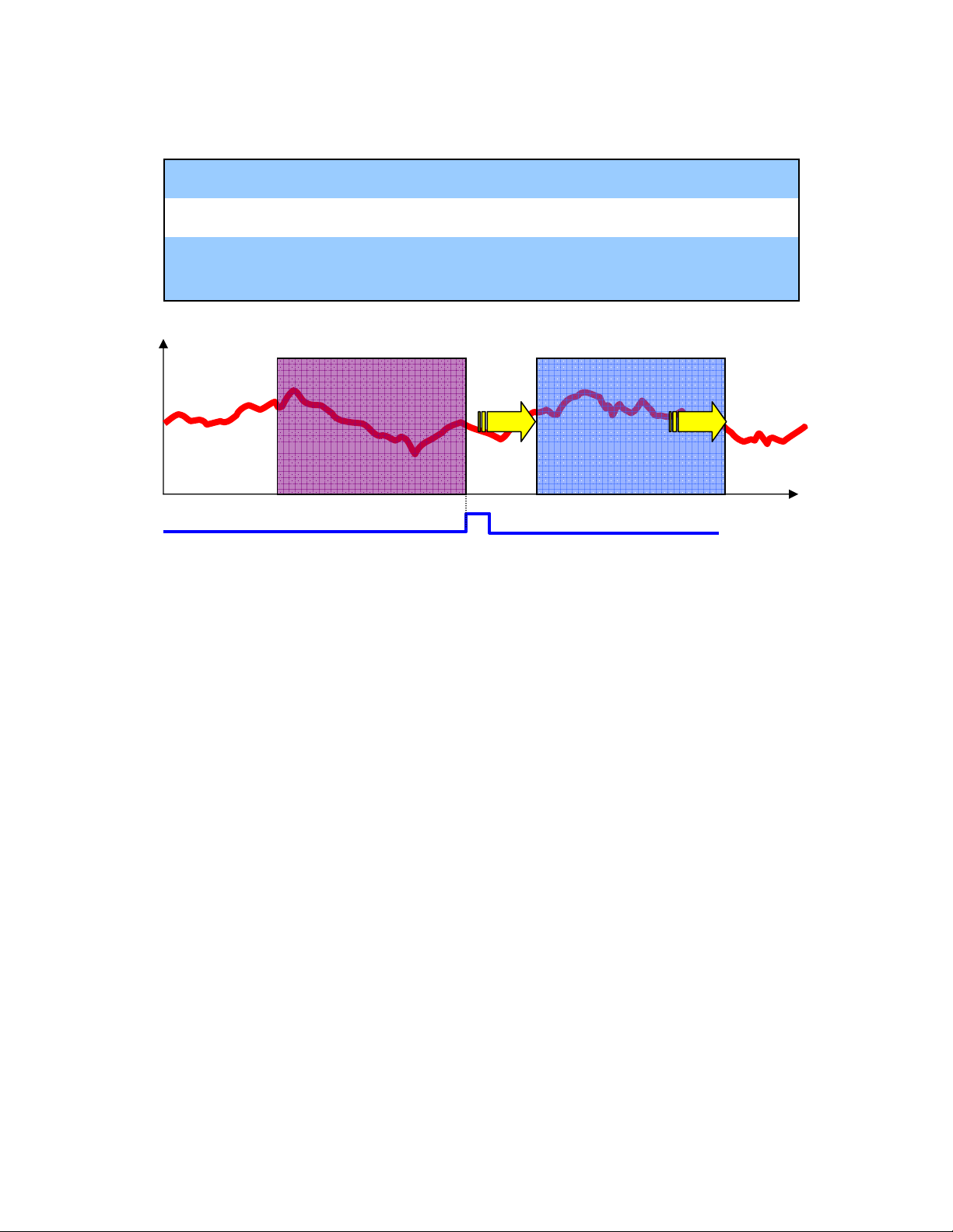
Data Trace
A
Quick Method
dd registers to
configuration
Snap the data
Illustration
trace
Save
R-Click in ladder, select "register to trace", or type registers manually. To
graph speed, create it in ladder using position scan differential.
CTRL-S or from menu. The selected data starts filling the trace buffer
(FIFO) immediately
Click the Snap button to display the data currently in the trace buffer. Click
Snap AFTER the motion completes. Although the data displayed is fixed,
data continues to fill the buffer.
Notes
Old Data
data
Snap
By default, the data saved in the list is updated every H-scan
The trace buffer is limited to 32,000 16-bit words per "group". Once it is full, old data is
pushed out by the new data.
Four (4) groups of trace data can be collected simultaneously.
Set the trigger condition to capture an event, such as a fault, or to change sample rate.
Snap Data Current Data
time
Page 13
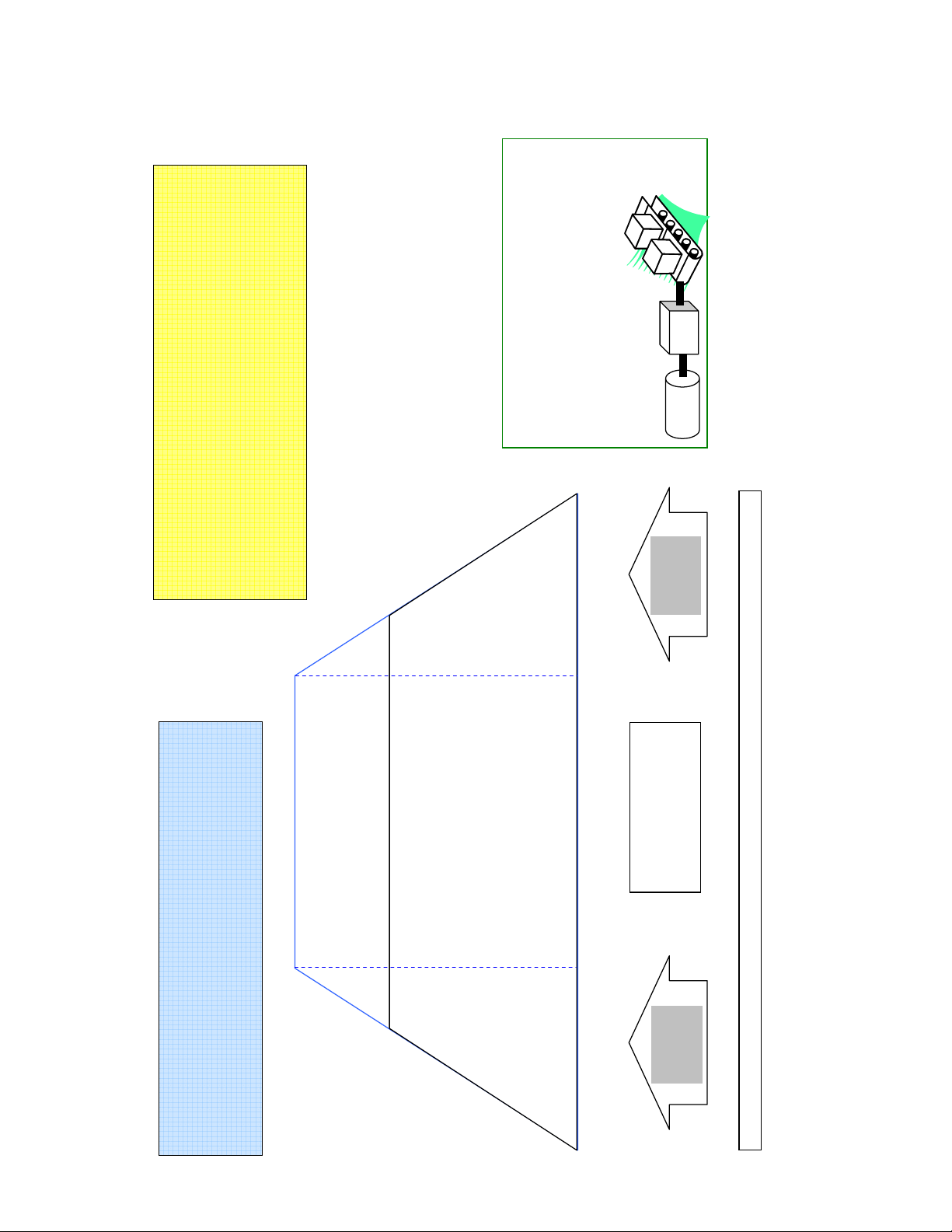
RU = FP17 bits0-3
p
A
0: Pulse (post quad)
1: mm
2: deg
3: inch
19
22
G.B.
21
NOTES:
MP920 QRG Rev1.5
FP17 bit 4 =1 Activates RU Feature
arameters to define the relationship between
If PULSE is not chosen as the RU, use the following
* Register Addresses assume Circuit#1, Axis#1
* Reference Units not compatible with Function Block programming.
* Default Positioning units are [encoder pulses (post quad)]
* Default Speed Reference units are [1000 pulses/min]
* Default Accel/Decel units are [ms to rated motor rpm]
* MPE720 5.31B "Units" in module configuration do not update
* Motion Module Manual incorrectly lists MCC=11 and Decel (OLC00D) as
not used
n = 3 when FP17 bit 4 =0 (RU not used)
n = FP18 when FP17 bit 4 =1 (RU is used)
Motor
PULSE and RU.
FP8: Encoder Pulses (pre-quad) per motor rev
FP21: Motor Revs into gearbox
FP22: Machine Shaft Revs out of gearbox
FP19: RU per Machine Shaft Revolution
Servopack Pn80E: Deceleration Rate
[10,000 RU/sec^2] (Default 65535)
8
Use MCC=11
to change
Deceleration
OWC00D: Deceleration [ms to Rated Speed (FP7)] (Default 0)
NOT SVA
Use of MCC to change
Servopack Parameters
Applies to SVB ONLY and
Page 15 of 15
FP7: Rated Speed [RPM] (Default 3000)
KEY
* RU = "reference unit" = "user unit" = "command unit"
* FP = Fixed Parameter
* MCC = Motion Command Code (OWxx20)
* Register Values given for Circuit#1, Axis#/1
* Bold type represents default setting
OLC022: Speed Reference (when OBC001D=0) [10^n RU/min] (Default 3000)
OLC015: Speed Reference (when OBC001D=1) [0.01% of Rated Speed (FP7)] (Default 0)
OLC012: Position Reference [RU]
OBC001E: Incremental / Absolute
or
OLC028: Step Distance [RU]
OBC0212: Step Direction
Servopack Pn80B: Acceleration Rate
[10,000 RU/sec^2] (Default 65535)
cceleration
Use MCC=10
to change
OWC00C: Acceleration [ms to Rated Speed (FP7)] (Default 0)
OWC00C=0 & OWC00D =0 sets servopack acceleration/deceleration rate to 65535[10,000 RU/sec^2]
Reference Units (User Units)
 Loading...