


Machine Controller MP3000 Series
MP3200/MP3300
TROUBLESHOOTING MANUAL
MANUAL NO. SIEP C880725 01B
Overview of Troubleshooting
Troubleshooting with Indicators
and Displays
Troubleshooting using
the System Monitor
Troubleshooting Communications
and Motion Control
Troubleshooting Programming
and Debugging
Troubleshooting Connections
with the MPE720
Troubleshooting System Errors
MP3200/MP3300 Battery Replacement
Fan Replacement
1
2
3
4
5
6
7
8
9

Copyright © 2012 YASKAWA ELECTRIC CORPORATION
All rights reserved. No part of this publication may be reproduced, stored in a retrieval system, or transmitted, in any form, or by any means, mechanical, electronic, photocopying,
recording, or otherwise, without the prior written permission of Yaskawa. No patent liability is assumed with respect to the use of the information contained herein. Moreover,
because Yaskawa is constantly striving to improve its high-quality products, the information contained in this manual is subject to change without notice. Every precaution has been
taken in the preparation of this manual. Nevertheless, Yaskawa assumes no responsibility
for errors or omissions. Neither is any liability assumed for damages resulting from the use
of the information contained in this publication.

About this Manual
Chapter Title Troubleshooting
Chapter 1 Overview of Troubleshooting √
Chapter 2 Troubleshooting Errors with LED Indicators and Displays √
Chapter 3 Troubleshooting using the System Monitor √
Chapter 4 Troubleshooting Communications and Motion Control √
Chapter 5 Troubleshooting Programming and Debugging √
Chapter 6 Troubleshooting Connections with the MPE720 √
Chapter 7 Troubleshooting System Errors √
Chapter 8 MP3200/MP3300 Battery Replacement √
Chapter 9 Fan Replacement √
This manual describes troubleshooting the MP3200 and MP3300.
For information on troubleshooting Optional Modules, refer to the manual for your Optional Modules.
Read this manual carefully to ensure the correct usage of the Machine Controller in the control of your manufacturing system.
Keep this manual in a safe place so that it can be referred to whenever necessary.
Using this Manual
Basic Terms
Unless otherwise specified, the following definitions are used:
• MP3200: A generic name for the Power Supply Unit, CPU Unit, Base Unit, and Rack Expansion Interface
Unit.
• MP3300: A generic name for the CPU Module and Base Unit.
• MPE720: The Engineering Tool or a personal computer running the Engineering Tool
• PLC: A Programmable Logic Controller
• Machine Controller: An MP3000-series Machine Controller
• Motion Control Function Modules: The Function Modules in the Motion Modules and the Function Mod-
ules in the SVC, SVR, SVC 32, or SVR 32 built into the CPU Units/
CPU Modules.
Manual Configuration
This manual consists of the chapters listed in the following table. Read the chapters of this manual as required
for your application.
MPE720 Engineering Tool Version Number
In this manual, the operation of MPE720 is described using screen captures of MPE720 version 7.
iii

Important
Note
Example
Information
Terms
Copyrights
• DeviceNet is a registered trademark of the ODVA (Open DeviceNet Venders Association).
• Ethernet is a registered trademark of the Xerox Corporation.
• MPLINK is a registered trademark of Yaskawa Electric Corporation.
• Microsoft, Windows, Windows NT, and Internet Explorer are trademarks or registered trademarks of the
Microsoft Corporation.
• PROFIBUS is a trademark of the PROFIBUS User Organization.
• MECHATROLINK is a trademark of the MECHATROLINK Members Association.
• Other product names and company names are the trademarks or registered trademarks of the respective company. “TM” and the
®
mark do not appear with product or company names in this manual.
Visual Aids
The following aids are used to indicate certain types of information for easier reference.
Indicates precautions or restrictions that must be observed.
Indicates alarm displays and other precautions that will not result in machine damage.
Indicates items for which caution is required or precautions to prevent operating mistakes.
Indicates operating or setting examples.
Indicates supplemental information to deepen understanding or useful information.
Indicates definitions of difficult terms or terms that have not been previously explained in this
manual.
iv

Related Manuals
The following table lists the related manuals.
Be aware of all product specifications and restrictions to product application before you attempt to use any
product.
Category Manual Name Manual Number Contents
Describes the functions of the MP2000/
MP3000-series Machine Controllers and the
procedures that are required to use the
Machine Controller, from installation and
connections to settings, programming, trial
operation, and debugging.
Describes the specifications and system configuration of an MP3000-series MP3200
Machine Controller and the functions of the
CPU Unit.
Describes the specifications and system configuration of an MP3000-series MP3300
Machine Controller and the functions of the
CPU Module.
Describes the functions, specifications, operating methods, maintenance, inspections, and
troubleshooting of the MP2000-series MPU01 Multi-CPU Module.
Describes the specifications, system configuration, and communications connection
methods for the Ethernet communications
that are used with an MP3000-series Machine
Controller.
Describes the specifications, system configuration, and operating methods for the SVC,
SVC32, SVR, and SVR32 Motion Function
Modules that are used in an MP3000-series
Machine Controller.
Describes the functions, specifications, and
operating methods of the MP2000-series PO01 Motion Module.
Describes the functions, specifications, and
operating methods of the MP2000-series
SVA-01 Motion Module.
Describes the functions, specifications, and
operating methods of MP2000-series Motion
Modules (built-in Function Modules: SVB,
SVB-01, and SVR).
Describes the functions, specifications, and
operating methods of the MP2000-series PO01 Motion Module.
Continued on next page.
Basic
functionality
Communications
functionality
Motion
control
functionality
Machine Controller MP2000/MP3000
Series Machine Controller System
Setup Manual
Machine Controller MP3000 Series
MP3200
User’s Manual
Machine Controller MP3000 Series
MP3300
Product Manual
Machine Controller MP2000 Series
MPU-01 Multi-CPU Module
User’s Manual
Machine Controller MP3000 Series
Communications
User's Manual
Machine Controller MP3000 Series
Motion Control
User's Manual
Machine Controller MP2000 Series
Built-in SVB/SVB-01 Motion Module
User's Manual
Machine Controller MP2000 Series
SVC-01 Motion Module
User's Manual
Machine Controller MP2000 Series
SVA-01 Motion Module
User's Manual
Machine Controller MP2000 Series
Pulse Output Motion Module PO-01
User's Manual
SIEP C880725 00
SIEP C880725 10
SIEP C880725 21
SIEP C880781 05
SIEP C880725 12
SIEP C880725 11
SIEP C880700 33
SIEP C880700 41
SIEP C880700 32
SIEP C880700 28
v

Category Manual Name Manual Number Contents
Describes the ladder programming specifications and instructions of MP3000-series
Machine Controller.
Describes the motion programming and
sequence programming specifications and
instructions of MP3000-series Machine Controller.
Programming
Engineering
Tools
Machine Controller MP3000 Series
Ladder Programming Manual
Machine Controller MP3000 Series
Motion Programming Manual
MPE720 Version 7 System Integrated
Engineering Tool for MP2000/MP3000
Series Machine Controller
User’s Manual
SIEP C880725 13
SIEP C880725 14
SIEP C880761 03 Describes how to operate MPE720 version 7.
Continued from previous page.
vi
Safety Precautions
WARNING
CAUTION
CAUTION
PROHIBITED
MANDATORY
WARNING
The following signal words and marks are used to indicate safety precautions in this manual.
Information marked as shown below is important for safety. Always read this information and heed the precautions that are provided.
Indicates precautions that, if not heeded, could possibly result in loss of life or
serious injury.
Indicates precautions that, if not heeded, could result in relatively serious or
minor injury, or property damage.
If not heeded, even precautions classified as cautions ( ) can lead to
serious results depending on circumstances.
Indicates prohibited actions. For example, indicates prohibition of open
flame.
Indicates mandatory actions. For example, indicates that grounding is
required.
The following precautions are for storage, transportation, installation, wiring, operation, maintenance, inspection, and disposal. These precautions are important and must be observed.
General Precautions
• The installation must be suitable and it must be performed only by an experienced technician.
There is a risk of electrical shock or injury.
• Before connecting the machine and starting operation, make sure that an emergency stop procedure has been provided and is working correctly.
There is a risk of injury.
• Do not approach the machine after a momentary interruption to the power supply. When power
is restored, the Machine Controller and the device connected to it may start operation suddenly.
Provide safety measures in advance to ensure human safety when operation restarts.
There is a risk of injury.
• Do not touch anything inside the Machine Controller.
There is a risk of electrical shock.
• Do not remove the front cover, cables, connector, or options while power is being supplied.
There is a risk of electrical shock, malfunction, or damage.
• Do not damage, pull on, apply excessive force to, place heavy objects on, or pinch the cables.
There is a risk of electrical shock, operational failure of the Machine Controller, or burning.
• Do not attempt to modify the Machine Controller in any way.
There is a risk of injury or device damage.
vii

CAUTION
Storage and Transportation
• Do not store the Machine Controller in any of the following locations.
• Locations that are subject to direct sunlight
• Locations that are subject to ambient temperatures that exceed the storage conditions
• Locations that are subject to ambient humidity that exceeds the storage conditions
• Locations that are subject to rapid temperature changes and condensation
• Locations that are subject to corrosive or inflammable gas
• Locations that are subject to excessive dust, dirt, salt, or metallic powder
• Locations that are subject to water, oil, or chemicals
• Locations that are subject to vibration or shock
There is a risk of fire, electrical shock, or device damage.
• Hold onto the main body of the Machine Controller when transporting it.
Holding the cables or connectors may damage them or result in injury.
• Do not overload the Machine Controller during transportation. (Follow all instructions.)
There is a risk of injury or an accident.
• Never subject the Machine Controller to an atmosphere containing halogen (fluorine, chlorine,
bromine, or iodine) during transportation.
There is a risk of malfunction or damage.
• If disinfectants or insecticides must be used to treat packing materials such as wooden frames,
pallets, or plywood, the packing materials must be treated before the product is packaged, and
methods other than fumigation must be used.
Example: Heat treatment, where materials are kiln-dried to a core temperature of 56°C for 30 minutes or
more.
If the electronic products, which include stand-alone products and products installed in machines, are
packed with fumigated wooden materials, the electrical components may be greatly damaged by the
gases or fumes resulting from the fumigation process. In particular, disinfectants containing halogen,
which includes chlorine, fluorine, bromine, or iodine can contribute to the erosion of the capacitors.
viii

Installation
• Do not install the Machine Controller in any of the following locations.
• Locations that are subject to direct sunlight
• Locations that are subject to ambient temperatures that exceed the operating conditions
• Locations that are subject to ambient humidity that exceeds the operating conditions
• Locations that are subject to rapid temperature changes and condensation
• Locations that are subject to corrosive or inflammable gas
• Locations that are subject to excessive dust, dirt, salt, or metallic powder
• Locations that are subject to water, oil, or chemicals
• Locations that are subject to vibration or shock
There is a risk of fire, electrical shock, or device damage.
• Never install the Machine Controller in an atmosphere containing halogen (fluorine, chlorine,
bromine, or iodine).
There is a risk of malfunction or damage.
• Do not step on the Machine Controller or place heavy objects on the Machine Controller.
There is a risk of injury or an accident.
• Do not block the air exhaust ports on the Machine Controller. Do not allow foreign objects to
enter the Machine Controller.
There is a risk of internal element deterioration, malfunction, or fire.
• Always mount the Machine Controller in the specified orientation.
There is a risk of malfunction.
• Leave the specified amount of space between the Machine Controller, and the interior surface
of the control panel and other devices.
There is a risk of fire or malfunction.
• Do not subject the Machine Controller to strong shock.
There is a risk of malfunction.
• Suitable battery installation must be performed and it must be performed only by an experienced technician.
There is a risk of electrical shock, injury, or device damage.
• Do not touch the electrodes of the Battery.
Static electricity may damage the electrodes.
CAUTION
ix

CAUTION
Wiring
• Check the wiring to be sure it has been performed correctly.
There is a risk of motor run-away, injury, or accidents.
• Always use a power supply of the specified voltage.
There is a risk of fire or accident.
• In places with poor power supply conditions, ensure that the input power is supplied within the
specified voltage range.
There is a risk of device damage.
• Install breakers and other safety measures to provide protection against shorts in external wiring.
There is a risk of fire.
• Provide sufficient shielding when using the Machine Controller in the following locations.
• Locations that are subject to noise, such as from static electricity
• Locations that are subject to strong electromagnetic or magnetic fields
• Locations that are subject to radiation
• Locations that are near power lines
There is a risk of device damage.
• Configure the circuits to turn ON the power supply to the CPU Unit/CPU Module before the 24V I/O power supply. Refer to the following manual for details on circuits.
MP3000 Series CPU Unit Instructions (Manual No.: TOBP C880725 16)
MP3000 Series MP3300 CPU Module Instructions Manual (Manual No.: TOBP C880725 23)
If the power supply to the CPU Unit/CPU Module is turned ON after the external power supply, e.g., the
24-V I/O power supply, the outputs from the CPU Unit/CPU Module may momentarily turn ON when
the power supply to the CPU Unit/CPU Module turns ON. This can result in unexpected operation that
may cause injury or device damage.
• Provide emergency stop circuits, interlock circuits, limit circuits, and any other required safety
measures in control circuits outside of the Machine Controller.
There is a risk of injury or device damage.
• If you use MECHATROLINK I/O Modules, use the establishment of MECHATROLINK communications as an interlock output condition.
There is a risk of device damage.
• Connect the Battery with the correct polarity.
There is a risk of battery damage or explosion.
• Suitable battery replacement must be performed and it must be performed only by an experienced technician.
There is a risk of electrical shock, injury, or device damage.
• Do not touch the electrodes when replacing the Battery.
Static electricity may damage the electrodes.
• Select the I/O signal wires for external wiring to connect the Machine Controller to external
devices based on the following criteria:
• Mechanical strength
• Noise interference
• Wiring distance
• Signal voltage
x
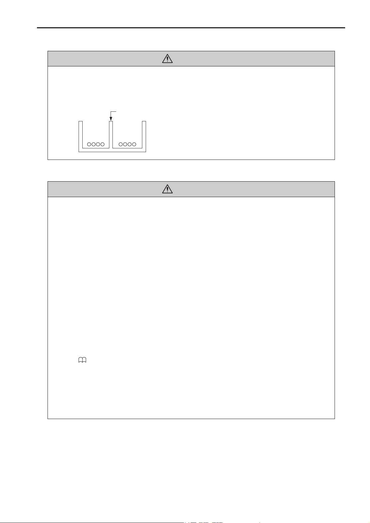
• Separate the I/O signal cables for control circuits from the power cables both inside and outside
Example of Separated Cables
Power cable
I/O signal
cables in
control circuits
Steel separator
the control panel to reduce the influence of noise from the power cables.
If the I/O signal lines and power lines are not separated properly, malfunction may occur.
Operation
CAUTION
CAUTION
• Follow the procedures and instructions in the user’s manuals for the relevant products to perform normal operation and trial operation.
Operating mistakes while the Servomotor and machine are connected may damage the machine or even
cause accidents resulting in injury or death.
• Implement interlock signals and other safety circuits external to the Machine Controller to
ensure safety in the overall system even if the following conditions occur.
• Machine Controller failure or errors caused by external factors
• Shutdown of operation due to Machine Controller detection of an error in self-diagnosis and the subse-
quent turning OFF or holding of output signals
• Holding of the ON or OFF status of outputs from the Machine Controller due to fusing or burning of out-
put relays or damage to output transistors
• Voltage drops from overloads or short-circuits in the 24-V output from the Machine Controller and the
subsequent inability to output signals
• Unexpected outputs due to errors in the power supply, I/O, or memory that cannot be detected by the
Machine Controller through self-diagnosis.
There is a risk of injury, device damage, or burning.
• Observe the setting methods that are given in the manual for the following parameters.
• Parameters for absolute position detection when the axis type is set to a finite-length axis
• Parameters for simple absolute infinite-length position control when the axis type is set to an infinite-
length axis
MP3000 Series Motion Control User’s Manual (Manual No. SIEP C880725 11)
If any other methods are used, offset in the current position when the power supply is turned OFF and ON
again may result in device damage.
•OL48 (Zero Point Position Offset in Machine Coordinate System) is always valid when
the axis type is set to a finite-length axis. Do not change the setting of OL48 while the
Machine Controller is operating.
There is a risk of machine damage or an accident.
xi
CAUTION
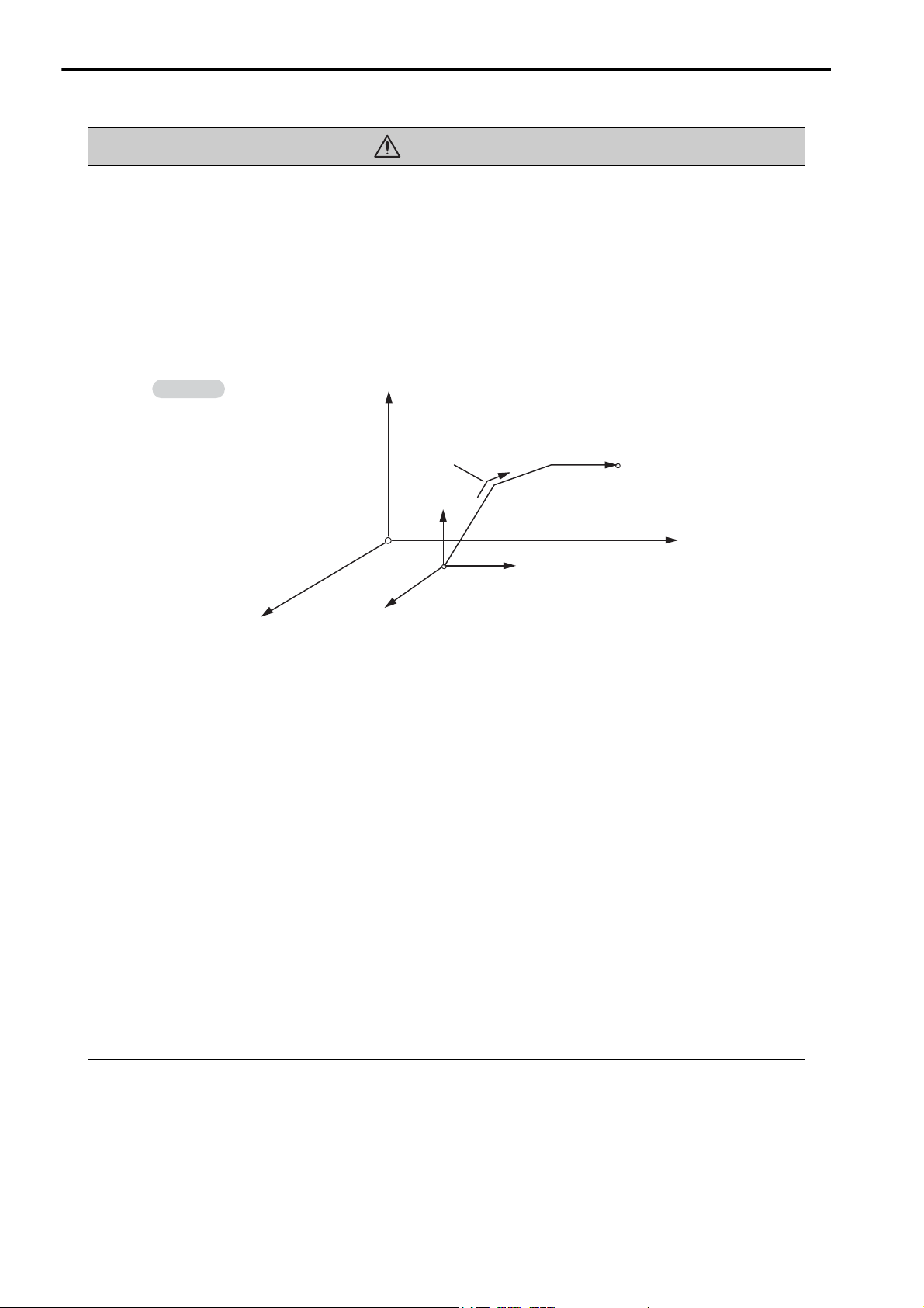
Example
Axis 1
Axis 2
Axis 3
Each axis is moved independently
at rapid traverse speed.
Current position
Positioning operation
End position
Axis 2
Axis 1
Axis 3
Example of Basic Path for Positioning (MOV) Instruction
• Always check to confirm the paths of axes when any of the following axis movement instructions are used in programs to ensure that the system operates safely.
• Positioning (MOV)
• Linear Interpolation (MVS)
• Circular Interpolation (MCC or MCW)
• Helical Interpolation (MCC or MCW)
• Set-time Positioning (MVT)
• Linear Interpolation with Skip Function (SKP)
• Zero Point Return (ZRN)
• External Positioning (EXM)
There is a risk of injury or device damage.
• The same coordinate word will create a completely different travel operation in Absolute Mode
and in Incremental Mode. Make sure that the ABS and INC instructions are used correctly
before you start operation.
There is a risk of injury or device damage.
• The travel path for the Positioning (MOV) instructions will not necessarily be a straight line.
Check to confirm the paths of the axis when this instruction is used in programs to ensure that
the system operates safely.
There is a risk of injury or device damage.
• The Linear Interpolation (MVS) instruction can be used on both linear axes and rotary axes.
However, if a rotary axis is included, the linear interpolation path will not necessarily be a
straight line. Check to confirm the paths of the axis when this instruction is used in programs to
ensure that the system operates safely.
There is a risk of injury or device damage.
• The linear interpolation for the Helical Interpolation (MCW and MCC) instructions can be used
for both linear axes and rotary axes. However, depending on how the linear axis is taken, the
path of helical interpolation will not be a helix. Check to confirm the paths of the axis when this
instruction is used in programs to ensure that the system operates safely.
There is a risk of injury or device damage.
xii
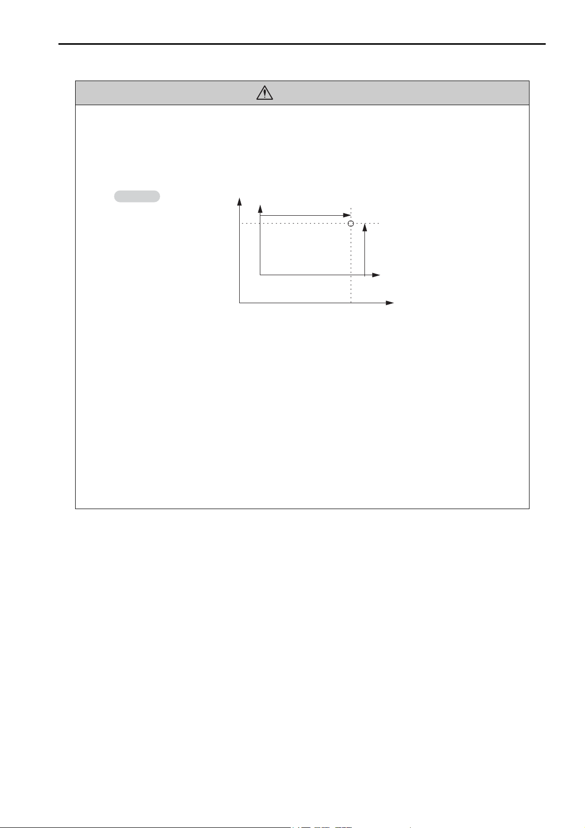
CAUTION
Example
Example of Working Coordinate System Created
with the Set Current Position (POS) Instruction
• Unexpected operation may occur if the following coordinate instructions are specified incorrectly: Always confirm that the following instructions are specified correctly before you begin
operation.
• Absolute Mode (ABS)
• Incremental Mode (INC)
• Current Position Set (POS)
Axis 2
Axis 2
(0, 0)
(0, 0)
Machine coordinate system
(Axis 1)
Working coordinate
system
Current
position
(Axis 2)
Axis 1
Axis 1
There is a risk of injury or device damage.
• The Set Current Position (POS) Instruction creates a new working coordinate system. Therefore, unexpected operation may occur if the POS instruction is specified incorrectly. When you
use the POS instruction, always confirm that the working coordinate system is in the correct
position before you begin operation.
There is a risk of injury or device damage.
• The Move on Machine Coordinates (MVM) instruction temporarily performs positioning to a
coordinate position in the machine coordinate system. Therefore, unexpected operation may
occur if the instruction is executed without confirming the zero point position in the machine
coordinate system first. When you use the MVM instruction, always confirm that the machine
zero point is in the correct position before you begin operation.
There is a risk of injury or device damage.
xiii

CAUTION
CAUTION
Maintenance and Inspection
• Do not attempt to disassemble or repair the Machine Controller.
There is a risk of electrical shock, injury, or device damage.
• Do not change any wiring while power is being supplied.
There is a risk of electrical shock, injury, or device damage.
• Suitable battery replacement must be performed and it must be performed only by an experienced technician.
There is a risk of electrical shock, injury, or device damage.
• Replace the Battery only while power is supplied to the Machine Controller.
Replacing the Battery while the power supply to the Machine Controller is turned OFF may result in loss
of the data stored in memory in the Machine Controller.
• When you replace the Battery, do not touch the electrodes of the Battery.
There is a risk of electrostatic discharge failure.
• Do not forget to perform the following tasks when you replace the CPU Unit/CPU Module:
• Back up all programs and parameters from the CPU Unit/CPU Module that is being replaced.
• Transfer all saved programs and parameters to the new CPU Unit/CPU Module.
If you operate the CPU Unit/CPU Module without transferring this data, unexpected operation may
occur. There is a risk of injury or device damage.
• Do not touch the heat sink on the CPU Unit/CPU Module while the power supply is turned ON
or for a sufficient period of time after the power supply is turned OFF.
The heat sink may be very hot, and there is a risk of burn injury.
Disposal
• Dispose of the Machine Controller as general industrial waste.
• Observe all local laws and ordinances when you dispose of used Batteries.
Other General Precautions
Observe the following general precautions to ensure safe application.
• The products shown in the illustrations in this manual are sometimes shown without covers or
protective guards. Always replace the cover or protective guard as specified first, and then
operate the products in accordance with the manual.
• The illustrations that are presented in this manual are typical examples and may not match the
product you received.
• If the manual must be ordered due to loss or damage, inform your nearest Yaskawa representative or one of the offices listed on the back of this manual.
xiv

Warranty
Details of Warranty
Warranty Period
The warranty period for a product that was purchased (hereinafter called “delivered product”) is one year from
the time of delivery to the location specified by the customer or 18 months from the time of shipment from the
Yaskawa factory, whichever is sooner.
Warranty Scope
Yaskawa shall replace or repair a defective product free of charge if a defect attributable to Yaskawa occurs
during the warranty period above. This warranty does not cover defects caused by the delivered product reaching the end of its service life and replacement of parts that require replacement or that have a limited service
life.
This warranty does not cover failures that result from any of the following causes.
• Improper handling, abuse, or use in unsuitable conditions or in environments not described in product catalogs or manuals, or in any separately agreed-upon specifications
• Causes not attributable to the delivered product itself
• Modifications or repairs not performed by Yaskawa
• Abuse of the delivered product in a manner in which it was not originally intended
• Causes that were not foreseeable with the scientific and technological understanding at the time of shipment
from Yaskawa
• Events for which Yaskawa is not responsible, such as natural or human-made disasters
Limitations of Liability
• Yaskawa shall in no event be responsible for any damage or loss of opportunity to the customer that arises
due to failure of the delivered product.
• Yaskawa shall not be responsible for any programs (including parameter settings) or the results of program
execution of the programs provided by the user or by a third party for use with programmable Yaskawa
products.
• The information described in product catalogs or manuals is provided for the purpose of the customer purchasing the appropriate product for the intended application. The use thereof does not guarantee that there
are no infringements of intellectual property rights or other proprietary rights of Yaskawa or third parties,
nor does it construe a license.
• Yaskawa shall not be responsible for any damage arising from infringements of intellectual property rights
or other proprietary rights of third parties as a result of using the information described in catalogs or manuals.
xv

Suitability for Use
• It is the customer’s responsibility to confirm conformity with any standards, codes, or regulations that apply
if the Yaskawa product is used in combination with any other products.
• The customer must confirm that the Yaskawa product is suitable for the systems, machines, and equipment
used by the customer.
• Consult with Yaskawa to determine whether use in the following applications is acceptable. If use in the
application is acceptable, use the product with extra allowance in ratings and specifications, and provide
safety measures to minimize hazards in the event of failure.
• Outdoor use, use involving potential chemical contamination or electrical interference, or use in conditions or
environments not described in product catalogs or manuals
• Nuclear energy control systems, combustion systems, railroad systems, aviation systems, vehicle systems, medical equipment, amusement machines, and installations subject to separate industry or government regulations
• Systems, machines, and equipment that may present a risk to life or property
• Systems that require a high degree of reliability, such as systems that supply gas, water, or electricity, or systems
that operate continuously 24 hours a day
• Other systems that require a similar high degree of safety
• Never use the product for an application involving serious risk to life or property without first ensuring that
the system is designed to secure the required level of safety with risk warnings and redundancy, and that the
Yaskawa product is properly rated and installed.
• The circuit examples and other application examples described in product catalogs and manuals are for reference. Check the functionality and safety of the actual devices and equipment to be used before using the
product.
• Read and understand all use prohibitions and precautions, and operate the Yaskawa product correctly to prevent accidental harm to third parties.
Specifications Change
The names, specifications, appearance, and accessories of products in product catalogs and manuals may be
changed at any time based on improvements and other reasons. The next editions of the revised catalogs or
manuals will be published with updated code numbers. Consult with your Yaskawa representative to confirm
the actual specifications before purchasing a product.
xvi

1
Contents
About this Manual. . . . . . . . . . . . . . . . . . . . . . . . . . . . . . . . . . . . . . . . . . . . . . . . . . . . . . . . . iii
Using this Manual. . . . . . . . . . . . . . . . . . . . . . . . . . . . . . . . . . . . . . . . . . . . . . . . . . . . . . . . . iii
Related Manuals . . . . . . . . . . . . . . . . . . . . . . . . . . . . . . . . . . . . . . . . . . . . . . . . . . . . . . . . . v
Safety Precautions . . . . . . . . . . . . . . . . . . . . . . . . . . . . . . . . . . . . . . . . . . . . . . . . . . . . . . . vii
Warranty. . . . . . . . . . . . . . . . . . . . . . . . . . . . . . . . . . . . . . . . . . . . . . . . . . . . . . . . . . . . . . . xv
Overview of Troubleshooting
2
3
1.1
1.2
Basic Troubleshooting Procedure. . . . . . . . . . . . . . . . . . . . . . . . . . . . . . . 1-2
Checking for Errors. . . . . . . . . . . . . . . . . . . . . . . . . . . . . . . . . . . . . . . . . . 1-3
Troubleshooting with Indicators and Displays
2.1
2.2
2.3
Power Indicators. . . . . . . . . . . . . . . . . . . . . . . . . . . . . . . . . . . . . . . . . . . . 2-2
Power Supply Unit Indicators (MP3200) . . . . . . . . . . . . . . . . . . . . . . . . . . . . . . . . . . . . . 2-2
Base Unit Indicators (MP3300) . . . . . . . . . . . . . . . . . . . . . . . . . . . . . . . . . . . . . . . . . . . . 2-2
CPU Unit/CPU Module Indicators and Display . . . . . . . . . . . . . . . . . . . . . 2-3
Status Indicators. . . . . . . . . . . . . . . . . . . . . . . . . . . . . . . . . . . . . . . . . . . . . . . . . . . . . . . . 2-3
Display . . . . . . . . . . . . . . . . . . . . . . . . . . . . . . . . . . . . . . . . . . . . . . . . . . . . . . . . . . . . . . . 2-7
USB Status Indicator . . . . . . . . . . . . . . . . . . . . . . . . . . . . . . . . . . . . . . . . . . . . . . . . . . . 2-15
MECHATROLINK-III Status Indicators . . . . . . . . . . . . . . . . . . . . . . . . . . . . . . . . . . . . . . 2-16
Ethernet Connector Indicators . . . . . . . . . . . . . . . . . . . . . . . . . . . . . . . . . . . . . . . . . . . . 2-17
Rack Expansion Interface Unit Indicators. . . . . . . . . . . . . . . . . . . . . . . . 2-18
Troubleshooting using the System Monitor
4
3.1
3.2
Overview of the System Monitor. . . . . . . . . . . . . . . . . . . . . . . . . . . . . . . . 3-2
Troubleshooting Errors with the System Monitor . . . . . . . . . . . . . . . . . . . 3-3
System Errors. . . . . . . . . . . . . . . . . . . . . . . . . . . . . . . . . . . . . . . . . . . . . . . . . . . . . . . . . . 3-3
Scan Time Exceeded . . . . . . . . . . . . . . . . . . . . . . . . . . . . . . . . . . . . . . . . . . . . . . . . . . . . 3-4
Investigating Operation Errors . . . . . . . . . . . . . . . . . . . . . . . . . . . . . . . . . . . . . . . . . . . . . 3-5
Investigating I/O Errors. . . . . . . . . . . . . . . . . . . . . . . . . . . . . . . . . . . . . . . . . . . . . . . . . . . 3-8
Troubleshooting Communications and Motion Control
4.1
Troubleshooting Ethernet Communications . . . . . . . . . . . . . . . . . . . . . . . 4-2
Checking Ethernet Cables . . . . . . . . . . . . . . . . . . . . . . . . . . . . . . . . . . . . . . . . . . . . . . . . 4-4
Checking the Ethernet Communications Mode . . . . . . . . . . . . . . . . . . . . . . . . . . . . . . . . 4-4
Troubleshooting Quick Reference . . . . . . . . . . . . . . . . . . . . . . . . . . . . . . . . . . . . . . . . . . 4-5
xvii

5
6
4.2
Troubleshooting Motion Errors . . . . . . . . . . . . . . . . . . . . . . . . . . . . . . . . .4-7
Troubleshooting Motion Errors. . . . . . . . . . . . . . . . . . . . . . . . . . . . . . . . . . . . . . . . . . . . . . 4-8
Checking Status and Alarms of a Reference-type SERVOPACK
with MECHATROLINK-III Communications . . . . . . . . . . . . . . . . . . . . . . . . . . . . . . . . . . . 4-21
Troubleshooting Programming and Debugging
5.1
5.2
Troubleshooting Motion Program Alarms . . . . . . . . . . . . . . . . . . . . . . . . .5-2
Checking for Motion Program Alarms . . . . . . . . . . . . . . . . . . . . . . . . . . . . . . . . . . . . . . . . 5-2
Structure of Motion Program Alarms . . . . . . . . . . . . . . . . . . . . . . . . . . . . . . . . . . . . . . . . .5-5
Motion Program Alarm Codes . . . . . . . . . . . . . . . . . . . . . . . . . . . . . . . . . . . . . . . . . . . . . . 5-6
Troubleshooting Message Communications. . . . . . . . . . . . . . . . . . . . . .5-10
Checking the Switch Settings . . . . . . . . . . . . . . . . . . . . . . . . . . . . . . . . . . . . . . . . . . . . .5-13
Message Communications Errors . . . . . . . . . . . . . . . . . . . . . . . . . . . . . . . . . . . . . . . . . . 5-14
Communications Stopped during Message Communications . . . . . . . . . . . . . . . . . . . . .5-36
Other Problems during Message Communications . . . . . . . . . . . . . . . . . . . . . . . . . . . . .5-38
Troubleshooting Connections with the MPE720
7
6.1
6.2
6.3
6.4
6.5
6.6
Troubleshooting Flowchart When the MPE720 Cannot Go Online with the Machine Controller
Checking for Errors . . . . . . . . . . . . . . . . . . . . . . . . . . . . . . . . . . . . . . . . . .6-3
Connection Errors . . . . . . . . . . . . . . . . . . . . . . . . . . . . . . . . . . . . . . . . . . . . . . . . . . . . . . . 6-3
Communications Errors . . . . . . . . . . . . . . . . . . . . . . . . . . . . . . . . . . . . . . . . . . . . . . . . . . .6-3
Model Errors . . . . . . . . . . . . . . . . . . . . . . . . . . . . . . . . . . . . . . . . . . . . . . . . . . . . . . . . . . .6-4
Checking the IP Address of the PC . . . . . . . . . . . . . . . . . . . . . . . . . . . . .6-5
Checking the Communications Settings . . . . . . . . . . . . . . . . . . . . . . . . . .6-7
Checking the Communications Platform. . . . . . . . . . . . . . . . . . . . . . . . .6-10
Communications Timeout Errors . . . . . . . . . . . . . . . . . . . . . . . . . . . . . .6-12
Troubleshooting System Errors
7.1
7.2
Overall Configuration of the System Registers . . . . . . . . . . . . . . . . . . . . .7-2
Viewing the Contents of the System Registers. . . . . . . . . . . . . . . . . . . . .7-4
. .6-2
xviii
7.3
7.4
Troubleshooting for the ERR Indicator . . . . . . . . . . . . . . . . . . . . . . . . . . .7-5
Troubleshooting for the ALM Indicator . . . . . . . . . . . . . . . . . . . . . . . . . . .7-6

7.5
System Register Configuration and Error Status . . . . . . . . . . . . . . . . . . . 7-7
CPU System Status . . . . . . . . . . . . . . . . . . . . . . . . . . . . . . . . . . . . . . . . . . . . . . . . . . . . . 7-7
System Error Status . . . . . . . . . . . . . . . . . . . . . . . . . . . . . . . . . . . . . . . . . . . . . . . . . . . . . 7-9
User Operation Error Status in Ladder Programs . . . . . . . . . . . . . . . . . . . . . . . . . . . . . .7-11
System Service Execution Status. . . . . . . . . . . . . . . . . . . . . . . . . . . . . . . . . . . . . . . . . . 7-14
System I/O Error Status . . . . . . . . . . . . . . . . . . . . . . . . . . . . . . . . . . . . . . . . . . . . . . . . . 7-15
Security Status . . . . . . . . . . . . . . . . . . . . . . . . . . . . . . . . . . . . . . . . . . . . . . . . . . . . . . . . 7-15
USB-related System Status . . . . . . . . . . . . . . . . . . . . . . . . . . . . . . . . . . . . . . . . . . . . . . 7-16
Message Relaying Status. . . . . . . . . . . . . . . . . . . . . . . . . . . . . . . . . . . . . . . . . . . . . . . . 7-16
Error Status for Individual Products . . . . . . . . . . . . . . . . . . . . . . . . . . . . . . . . . . . . . . . . 7-17
Interrupt Status. . . . . . . . . . . . . . . . . . . . . . . . . . . . . . . . . . . . . . . . . . . . . . . . . . . . . . . . 7-34
Module Information. . . . . . . . . . . . . . . . . . . . . . . . . . . . . . . . . . . . . . . . . . . . . . . . . . . . . 7-36
MPU-01 System Status . . . . . . . . . . . . . . . . . . . . . . . . . . . . . . . . . . . . . . . . . . . . . . . . . 7-47
Motion Program Execution Information . . . . . . . . . . . . . . . . . . . . . . . . . . . . . . . . . . . . . 7-48
Extended System I/O Error Status . . . . . . . . . . . . . . . . . . . . . . . . . . . . . . . . . . . . . . . . . 7-59
Extended Unit and Module Information . . . . . . . . . . . . . . . . . . . . . . . . . . . . . . . . . . . . . 7-64
Extended System Status . . . . . . . . . . . . . . . . . . . . . . . . . . . . . . . . . . . . . . . . . . . . . . . . 7-69
Extended System Service Execution Status . . . . . . . . . . . . . . . . . . . . . . . . . . . . . . . . . 7-70
Alarm History Information. . . . . . . . . . . . . . . . . . . . . . . . . . . . . . . . . . . . . . . . . . . . . . . . 7-70
Product Information . . . . . . . . . . . . . . . . . . . . . . . . . . . . . . . . . . . . . . . . . . . . . . . . . . . . 7-72
Unit and Rack Information . . . . . . . . . . . . . . . . . . . . . . . . . . . . . . . . . . . . . . . . . . . . . . . 7-73
Data Logging Execution Status . . . . . . . . . . . . . . . . . . . . . . . . . . . . . . . . . . . . . . . . . . . 7-75
Automatic Reception Status (Ethernet Communications) . . . . . . . . . . . . . . . . . . . . . . . 7-76
8
9
MP3200/MP3300 Battery Replacement
8.1
8.2
MP3200 Battery Replacement . . . . . . . . . . . . . . . . . . . . . . . . . . . . . . . . . 8-2
MP3300 Battery Replacement . . . . . . . . . . . . . . . . . . . . . . . . . . . . . . . . . 8-5
Fan Replacement
Index
Revision History
xix

Overview of Troubleshooting
This chapter describes the basic troubleshooting and error confirmation procedures.
1
1.1
1.2
Basic Troubleshooting Procedure . . . . . . . . . . . . 1-2
Checking for Errors . . . . . . . . . . . . . . . . . . . . . . . 1-3
1.1 Basic Troubleshooting Procedure
1.1
Basic Troubleshooting Procedure
When a problem occurs, it is important to recover normal system operation as soon as possible by finding
the cause of the problem and taking the necessary measures. The basic troubleshooting procedure is outlined below.
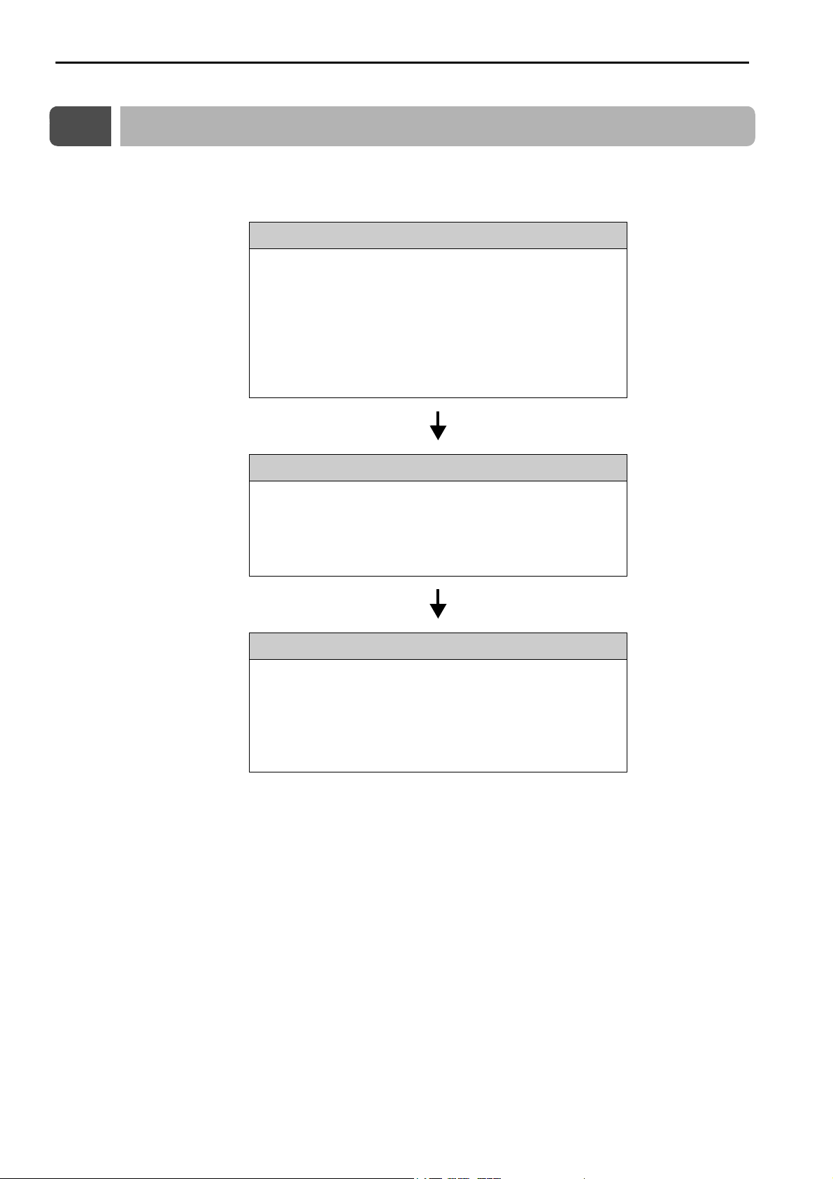
Step 1
Check the following items visually.
• Machine movement, or status if stopped
• Power supply status
• I/O device status
• Wiring conditions
• Status of indicators and display on Units or Modules
• Switch settings (e.g., DIP switches)
• Parameter settings and program contents
Step 2
See if the problem changes when the following operations are performed.
• Stop the Machine Controller.
• Reset the alarms.
• Turn the power supply OFF and ON again.
Step 3
Isolate the location of the problem from the results of steps 1 and 2.
• Inside or outside of the Machine Controller?
• Software or hardware?
• Sequence control or motion control?
• Ethernet communications or MECHATROLINK communications?
1-2

1.2 Checking for Errors
Overview of Troubleshooting
Information
1.2
Checking for Errors
This section describes the errors that can occur when using the Machine Controller, and how to troubleshoot them.
Follow the troubleshooting procedures outlined below if a problem occurs with the Machine Controller.
1.
Check the status of the indicators on the Machine Controller.
Refer to the following sections for details on checking the status of indicators on the Machine Controller.
2.1 Power Indicators (page 2-2)
2.2 CPU Unit/CPU Module Indicators and Display (page 2-3)
2. Connect the MPE720 to the Machine Controller to check the error information.
If the CPU Unit/CPU Module is not functioning properly, check the status of the indicators on the CPU
Unit/CPU Module. Then use the MPE720 to check for errors.
• If a system error and a scan time exceeded error have occurred:
Chapter 3 Troubleshooting using the System Monitor
• If an Ethernet communications error or a motion control error has occurred:
Chapter 4 Troubleshooting Communications and Motion Control
• If an error occurred in a motion program or during message communications:
Chapter 5 Troubleshooting Programming and Debugging
• If you cannot go online with the MPE720:
Chapter 6 Troubleshooting Connections with the MPE720
• If you want to investigate a system error:
Chapter 7 Troubleshooting System Errors
1-3

Troubleshooting with Indicators and Displays
This chapter describes troubleshooting procedures with the indicators and the display on the Machine Controller.
2
2.1
2.2
2.3
Power Indicators . . . . . . . . . . . . . . . . . . . . . . . . . 2-2
Power Supply Unit Indicators (MP3200) . . . . . . . . . . . . . . . . . 2-2
Base Unit Indicators (MP3300) . . . . . . . . . . . . . . . . . . . . . . . . 2-2
CPU Unit/CPU Module Indicators and Display . . 2-3
Status Indicators . . . . . . . . . . . . . . . . . . . . . . . . . . . . . . . . . . . 2-3
Display . . . . . . . . . . . . . . . . . . . . . . . . . . . . . . . . . . . . . . . . . . 2-7
USB Status Indicator . . . . . . . . . . . . . . . . . . . . . . . . . . . . . . 2-15
MECHATROLINK-III Status Indicators . . . . . . . . . . . . . . . . . 2-16
Ethernet Connector Indicators . . . . . . . . . . . . . . . . . . . . . . . 2-17
Rack Expansion Interface Unit Indicators . . . . . 2-18
2.1 Power Indicators
POWER
Power Supply Unit Indicators (MP3200)
2.1
Power Indicators
You can check the power supply loading status with the power indicators on the MP3000.
With the MP3200, the indicators are on the Power Supply Unit, and with the MP3300, there is an indicator
on the Base Unit. This section describes the power indicators for the MP3200 and MP3300.
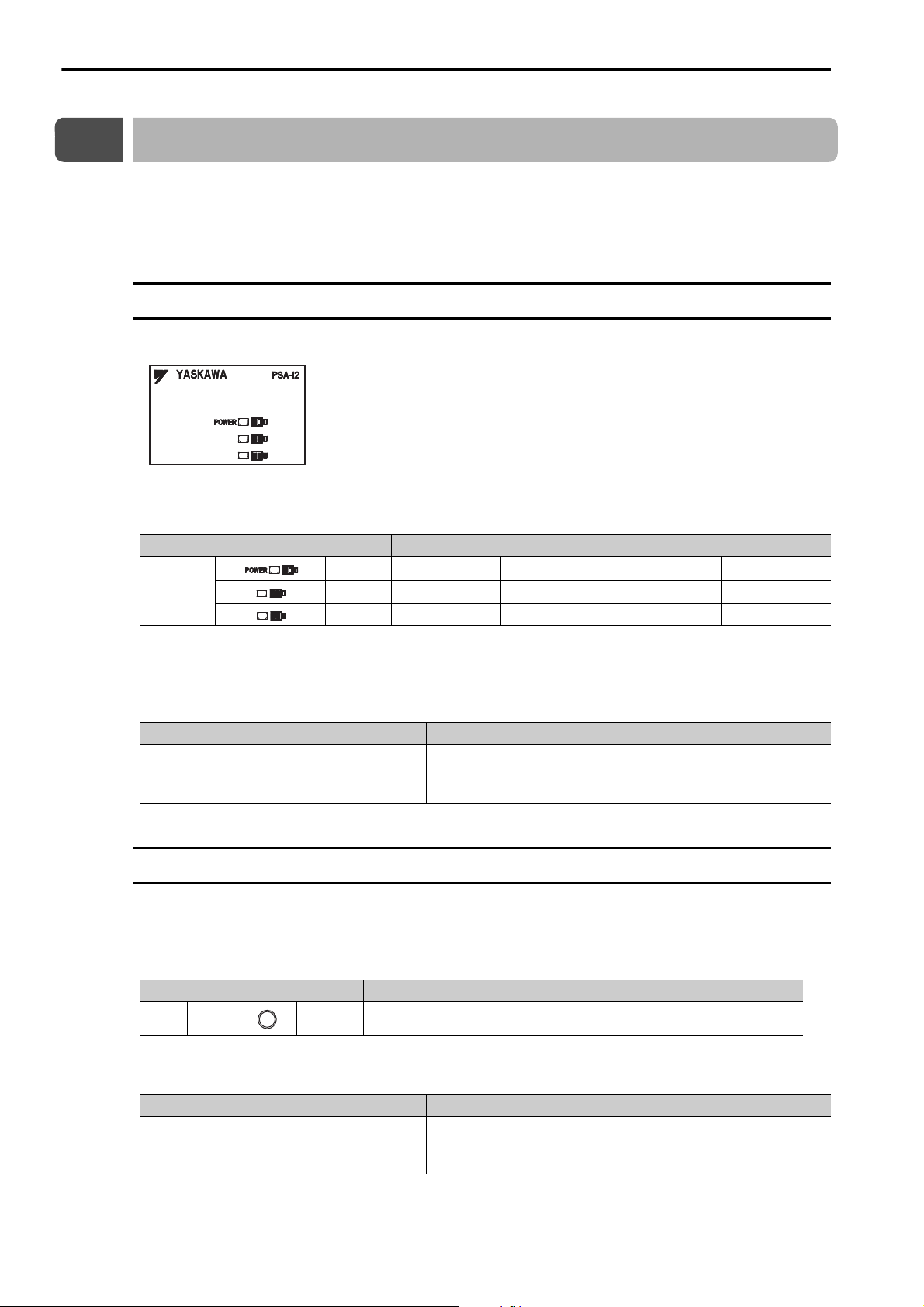
Power Supply Unit Indicators (MP3200)
This section describes how to check the load on the Power Supply Unit.
The following table gives the relation between the indicators on the Power Supply Unit and the load on the
Power Supply Unit.
Load Normal Error
Green
Indicators
Note: 1. : Lit, : Not lit.
2. The indicators show the status when the Power Supply Unit is turned ON.
Check the status in the above table and perform the actions given below if the power loading status indicates an error.
Ye ll o w
Red
Load Cause Correction
• Reduce the number of Optional Modules installed on the Base
Unit.
• Reduce the number of Units.
Error
The load exceeds the
capacity of the Power Supply Unit.
Base Unit Indicators (MP3300)
With the MP3300, you can check the power supply loading status on the Base Unit.
The following table shows the relation between the load status of the Rack power supply and the indicator
on the Power Supply Unit.
Load Normal Error
LED Green
Check the status in the above table and perform the actions given below if the power loading status indicates an error.
Load Cause Correction
Error
The load exceeds the
capacity of the Power Supply Unit.
Reduce the number of Optional Modules installed on the Base
Unit.
2-2
2.2 CPU Unit/CPU Module Indicators and Display
Troubleshooting with Indicators and Displays
Status Indicators
2.2
CPU Unit/CPU Module Indicators and Display
You can use the indicators on the CPU Unit/CPU Module to check the error status of the CPU Unit/CPU
Module.
After you check the error status, the system (S) registers will help you isolate the program location that
needs to be corrected.
Refer to the following chapter for details on system registers.
Chapter 7 Troubleshooting System Errors
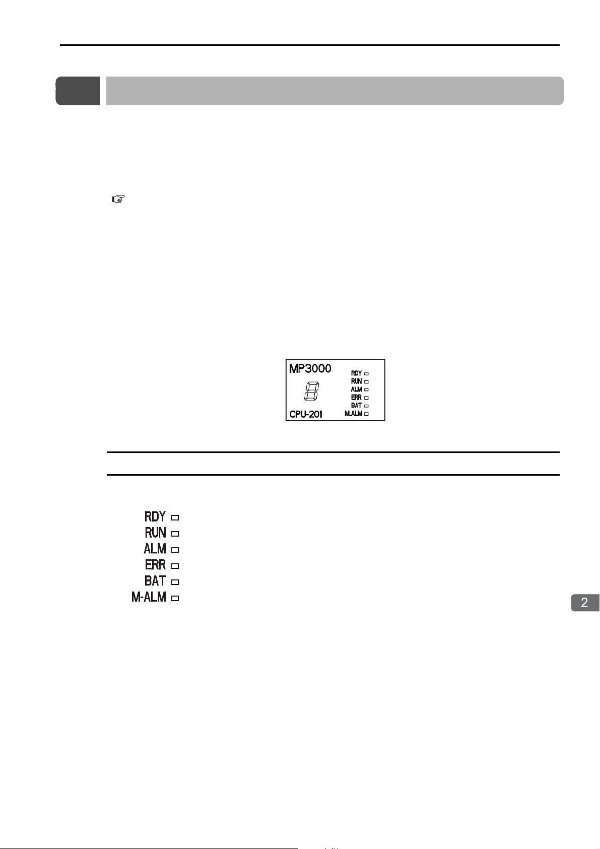
The CPU Unit/CPU Module has the following display and four types of indicators.
•Display
• Status indicators
• USB status indicator
• MECHATROLINK-III status indicators
• Ethernet status indicators
The error status and error details can be checked using the above display and indicators.
The display and indicators will give you a general idea of what the error is and the system (S) registers will
help you isolate the program location that needs to be corrected.
Status Indicators
These indicators show the status of the CPU Unit/CPU Module.
2-3

2.2 CPU Unit/CPU Module Indicators and Display
Status Indicators
The patterns of the status indicators are described in the following table.
Indicator Status
RDY
(Green)
RUN
(Green)
ALM
(Red)
ERR
(Red)
− Hardware reset Normally, the CPU Unit
− Initialization
−
Normal
−
−
Note: : Not lit, : Lit, : Flashing, −: Any status
BAT
(Red)
M_ALM
(Red)
CPU Unit/CPU
Module Status
Drawing A is being
executed.
The user programs
are stopped (offline
stop mode).
The user programs
are being executed
normally.
Description
will start within 10 seconds. If more than 10
seconds is required,
there is an error in a user
program or a hardware
error. Refer to the following section for information on system errors
and implement corrections.
Chapter 7 Troubleshooting System
Errors
• The stop operation
was performed from
the MPE720.
• This is the status after
the STOP switch is
turned ON. It is not an
error.
Normal operation is in
progress.
Continued on next page.
2-4

2.2 CPU Unit/CPU Module Indicators and Display
Troubleshooting with Indicators and Displays
Indicator Status
RDY
(Green)
RUN
(Green)
ALM
(Red)
ERR
(Red)
BAT
(Red)
M_ALM
(Red)
−
Error
−
−−−−− Motion error
CPU Unit/CPU
Module Status
A serious failure
error occurred.
Software Errors:
Number of Flashes
2: Machine check
exception
3: DSI (writing)
exception
4: ISI exception
5: Alignment
exception
6: DDR DRAM
memory error
exception
7: DTLB exception
8: ITLB exception
Hardware Errors:
Number of Flashes
2: RAM diagnostic error
3: ROM diagnostic error
4: CPU Function
Module diagnostic error
5: FPU Function
Module diagnostic error
Status Indicators
Continued from previous page.
Description
If the ERR indicator is
lit, there is a hardware
failure or a user program
error. Refer to the following section for the
corrective actions to take
when the ERR indicator
is lit.
7.3 Troubleshooting
for the ERR Indicator
(page 7-5)
A hardware failure has
occurred. Replace the
Unit or Module.
If the M_ALM indicator is lit, there is an error
in the Motion Control
Function Module. Refer
to the following section
for details on motion
errors.
4.2 Troubleshooting
Motion Errors (page
4-7)
Continued on next page.
2-5

2.2 CPU Unit/CPU Module Indicators and Display
Status Indicators
Indicator Status
RDY
(Green)
RUN
(Green)
ALM
(Red)
−−−− − Battery alarm
Alarms
−−
Note: : Not lit, : Lit, : Flashing, −: Any status
ERR
(Red)
BAT
(Red)
M_ALM
(Red)
CPU Unit/CPU
Module Status
Operation error
I/O error
Continued from previous page.
Description
If the BAT indicator is
lit, the Battery must be
replaced. Refer to the
following section for the
Battery replacement procedure.
Chapter 8
MP3200/MP3300
Battery Replacement
If the ALM indicator is
lit, there is an operation
error or an I/O error.
Refer to the following
section for the corrective
actions to take when the
ALM indicator is lit.
7.4 Troubleshooting
for the ALM Indicator (page 7-6)
2-6

2.2 CPU Unit/CPU Module Indicators and Display
Troubleshooting with Indicators and Displays
Display
Display
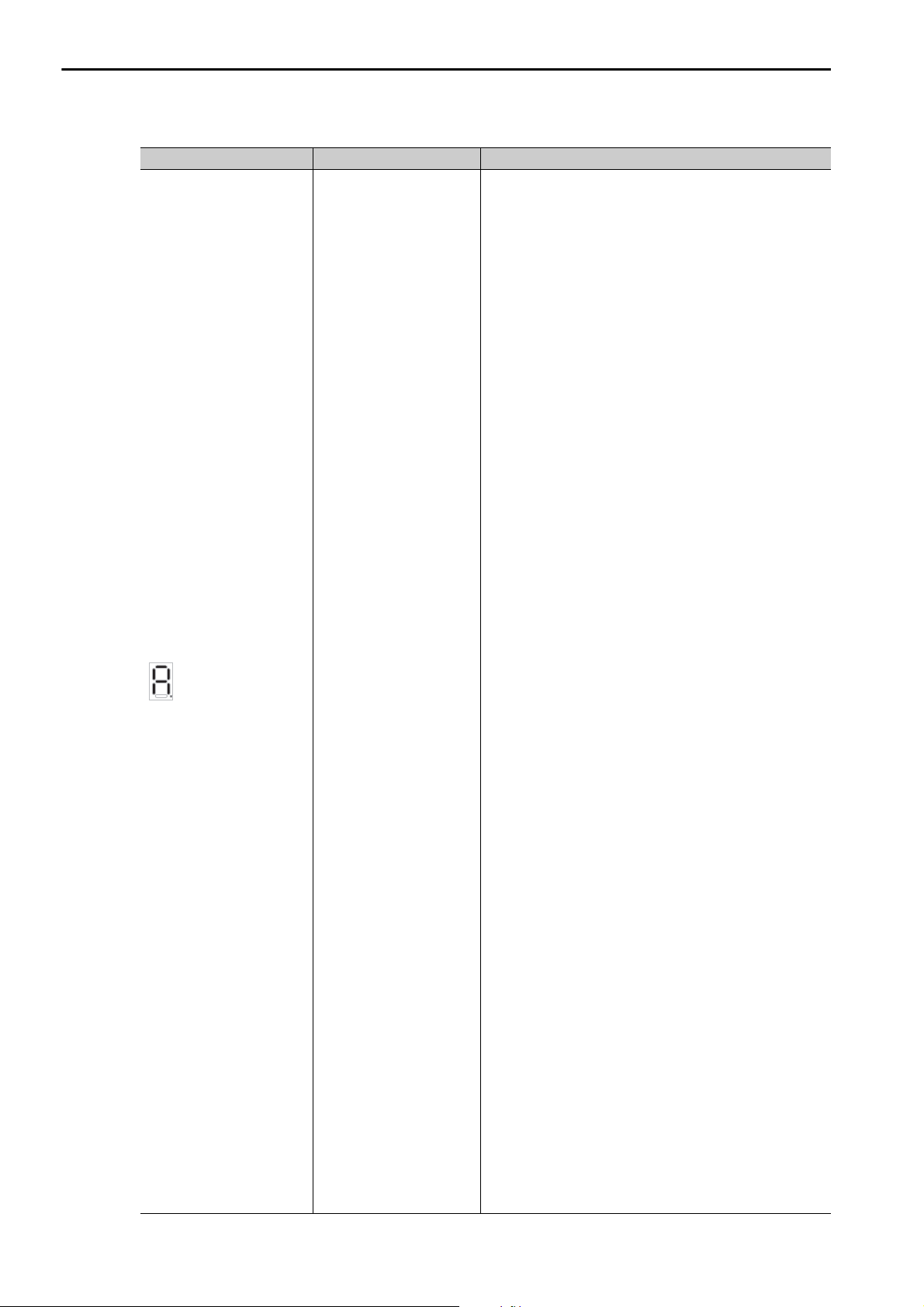
If an error or alarm occurs, details will be displayed on the display. This section describes the display patterns and corresponding errors.
Display Category Description
A 3-digit error code is displayed after E, like this:
E001: Watchdog timer error
E051: Module synchronization error
E052: Main CPU Unit system down detected
E061: Unit configuration error on Rack 1
E062: Unit configuration error on Rack 2
E063: Unit configuration error on Rack 3
E064: Unit configuration error on Rack 4
E065: Unit configuration error on Rack 5
E066: Unit configuration error on Rack 6
E067: Unit configuration error on Rack 7
E070: Unsupported Sub CPU mode
E071: Unsupported Module detected
E080: CPU mode mismatch
E081: CPU stopped for internal temperature error 1
E082 CPU stopped for internal temperature error 2
E083: Fan stopped
E090: Hardware error 1
E091: Hardware error 2
E092: Hardware error 3
Continued on next page.
followed by error
code
System error
2-7
2.2 CPU Unit/CPU Module Indicators and Display
Display
Display Category Description
followed by error
Alarm
code
Continued from previous page.
A 3-digit error code is displayed after A, like this:
A001: Operation error in DWG.A
A002: Operation error in DWG.I
A003: Operation error in DWG.H
A005: Operation error in DWG.L
A101: I/O error on Rack 1
A102: I/O error on Rack 2
A103: I/O error on Rack 3
A104: I/O error on Rack 4
A105: I/O error on Rack 5
A106: I/O error on Rack 6
A107: I/O error on Rack 7
A201: Insufficient power supply capacity warning 1 for
Rack 1
A205: Insufficient power supply capacity warning 1 for
Rack 5
A206: Insufficient power supply capacity warning 1 for
Rack 6
A207: Insufficient power supply capacity warning 1 for
Rack 7
A211: Insufficient power supply capacity warning 2 for
Rack 1
A215: Insufficient power supply capacity warning 2 for
Rack 5
A216: Insufficient power supply capacity warning 2 for
Rack 6
A217: Insufficient power supply capacity warning 2 for
Rack 7
A221: Power interruption detected on Expansion Rack 1
A225: Power interruption detected on Expansion Rack 5
A226: Power interruption detected on Expansion Rack 6
A227: Power interruption detected on Expansion Rack 7
A230: Hardware error 4
A240: Fan stopped
A241: Internal temperature rise detected
A301: USB memory write error
A302: USB memory read error
A303: Security error
A305: Folder for batch loading does not exist.
A306: Load file model mismatch error
A307: Loading error due to program write protection
A308: Load file write error
A309: Save to flash memory error
A30A:Save file read error
A30B: No USB memory device
A370: Log folder creation error
A371: Log file creation error
A372: Log file writing error
A401: M-III restrictions error
A402: Error in MPU-01
A403: Error in Sub CPU
Continued on next page.
2-8

2.2 CPU Unit/CPU Module Indicators and Display
Troubleshooting with Indicators and Displays
Continued from previous page.
Display Category Description
Display
followed by error
code
− h: CPU stopped by failsafe function
Troubleshooting Alarms
The following table describes the causes and corrections of alarms that are displayed on the display.
Checkmarks () indicate when the alarm codes are displayed by the MP3200 or MP3300.
Alarm Code
Alarm Name
E001:
Watchdog timer error
E051:
Module synchronization error
E052:
Main CPU Unit system down detected
MP3200
MP3300
There is an infinite loop in
a user program.
The maximum value of
the scan time does not
meet the following conditions.
• The scan times for the
• The set values must be
The main CPU failed.
A synchronization error
occurred for an Optional
Module.
A watchdog error
occurred in the Main CPU.
Cause Confirmation Method Correction
Check the FOR and
WHILE instructions for
the possibility of infinite
loops. Turn ON the STOP
switch and turn the power
supply OFF and ON again.
Check the set values of the
scan times for the highspeed (H) scan and the
low-speed (L) scan in relahigh-speed (H) scan and
the low-speed (L) scan
must be set to values that
are higher than the maximum scan times.
1.25 times the maximum
values.
tion to the maximum val-
ues of the scan times.
You can check the set val-
ues and maximum values
of the high-speed (H) scan
and the low-speed (L) scan
in SW00004 to SW00012.
Turn the power supply
OFF and ON again to see
if an alarm occurs. If an
alarm occurs even after the
power supply is turned
OFF and ON again several
times, the CPU may be
faulty.
Turn the power supply
OFF and ON again to see
if an alarm occurs. If an
alarm occurs even after the
power supply is turned
OFF and ON again several
times, the Optional Mod-
ule may be faulty.
Check the indicators or
system registers for the
Main CPU.
Correct the ladder program.
Correct the set values
of the scan times.
Replace the CPU.
Check the SW00076
system register to
identify the Optional
Module with the error
and replace the
Optional Module.
Clear the cause of the
watchdog error from
the Main CPU.
Continued on next page.
2-9

2.2 CPU Unit/CPU Module Indicators and Display
Display
Continued from previous page.
Alarm Code
Alarm Name
E061:
Unit configuration
error
E062:
Unit configuration
error
E063:
Unit configuration
error
E064:
Unit configuration
error
E065:
Unit configuration
error
E066:
Unit configuration
error
E067:
Unit configuration
error
E070:
Unsupported Sub
CPU mode
E071:
Unsupported Module
detected
E080:
CPU mode mismatch
E081:
CPU stopped for
internal temperature
error 1
E082:
CPU stopped for
internal temperature
error 2
E083:
Fan stopped (1 minute)
MP3200
MP3300
−
−
−
−
−
−
−
−
−
−
Cause Confirmation Method Correction
There is a configuration
error on Rack .
: 1 to 7
A CPU version that does
not support operation as a
Sub CPU was mounted as
a Sub CPU.
A Module that cannot be
used was mounted.
The Main CPU contains a
Sub CPU project.
Or a Sub CPU contains a
Main CPU project.
The te
mperature contin-
ued
to increase even further after A241 was
detected and is approaching the permissible temperature of the internal
parts.
The temperature continued to increase even after
E081 was detected and has
reached the permissible
temperature of the internal
parts.
The Fan stopped continuously for 1 minute.
Check the following conditions.
• There are more than
three MP3000 Units.
• There is more than one
MP2000 Unit.
• There is more than one
Sub CPU.
• There are more than two
Base Units.
• An MP2000 Unit is
mounted to Rack 5 to 7
(excluding to the right of
a Sub CPU).
• More than one EXIOIF
Module is mounted.
• An EXIOIF Module is
mounted under a Sub
CPU.
Check the system software version.
Check to see if the Modules are supported.
Log on from the MPE720
and check the Module configuration definitions.
Check SB00041F (temperature warning).
Check to see if the Fan is
operating.
Or, check SB00041E (Fan
error).
Correct the Unit configuration.
Use a version of the
CPU that supports
operation as a Sub
CPU.
Remove any Modules
that are not supported.
Transfer a Main CPU
project to the Main
CPU. Transfer a Sub
CPU project to the
Sub CPU.
Change the installation environment to
lower the temperature
around the CPU.
If the CPU temperature increases and an
error occurs, turn OFF
the power supply to
the Controller and
change the installation environment.
Check the Fan operation.
If the Fan is not operating, turn OFF the
power supply to the
Controller and replace
the Fan.
Continued on next page.
2-10

2.2 CPU Unit/CPU Module Indicators and Display
Troubleshooting with Indicators and Displays
Display
Continued from previous page.
Alarm Code
Alarm Name
E090:
Hardware error 1
E091:
Hardware error 2
E092:
Hardware error 3
A001
Operation error in
DWG.A
A002
Operation error in
DWG.I
A003
Operation error in
DWG.H
A005
Operation error in
DWG.L
A101:
I/O error on Rack 1
A102:
I/O error on Rack 2
A103:
I/O error on Rack 3
A104:
I/O error on Rack 4
A105:
I/O error on Rack 5
A106:
I/O error on Rack 6
A107:
I/O error on Rack 7
MP3200
MP3300
−
−
−
−
−
−
Cause Confirmation Method Correction
A hardware error
occurred.
There is an operation error
in DWG.A.
There is an operation error
in DWG.I.
There is an operation error
in DWG.H.
There is an operation error
in DWG.L.
There is an I/O error on a
Main Rack (Rack ).
: 1 to 7
Turn the power supply
OFF and ON again.
Check the error code in
SW00081.
Check the error code in
SW00083.
Check the error code in
SW00085.
Check the error code in
SW00089.
Check the error in
SW09560 to SW13699
(System I/O Error Status)
to identify the Module
with the error.
If the error persists
even when you turn
the power supply OFF
and ON again a few
times, there is a hardware failure.
Replace the Unit.
Correct the ladder program.
Remove the cause of
the I/O error based on
the error status.
Continued on next page.
2-11

2.2 CPU Unit/CPU Module Indicators and Display
Display
Continued from previous page.
Alarm Code
Alarm Name
A201:
Insufficient power
supply capacity warning 1 for Rack 1
A205:
Insufficient power
supply capacity warning 1 for Rack 5
A206:
Insufficient power
supply capacity warning 1 for Rack 6
A207:
Insufficient power
supply capacity warning 1 for Rack 7
A211:
Insufficient power
supply capacity warning 2 for Rack 1
A215:
Insufficient power
supply capacity warning 2 for Rack 5
A216:
Insufficient power
supply capacity warning 2 for Rack 6
A217:
Insufficient power
supply capacity warning 2 for Rack 7
A230:
Hardware error 4
A240:
Fan stopped
Cause Confirmation Method Correction
MP3200
MP3300
−
An Insufficient Power
Supply Capacity 1 Warning was detected on the
Main Rack (Rack ).
−
: 1 or 5 to 7
−
−
An Insufficient Power
Supply Capacity 2 Warning was detected on the
Main Rack (Rack ).
−
: 1 or 5 to 7
−
A hardware error
occurred.
− The fan stopped.
Check the indicators on the
Power Supply Unit.
Turn the power supply
OFF and ON again.
Check to see if the Fan is
operating.
Or, check SB00041E (Fan
error).
Check the configuration of the Optional
Modules and either
reduce the number of
Optional Modules or
replace the Power
Supply Unit.
If the error persists
even when you turn
the power supply OFF
and ON again a few
times, there is a hardware failure.
Replace the Unit with
the hardware failure.
• Connect the Fan correctly.
• If the Fan is not
operating, turn OFF
the power supply to
the Controller and
replace the Fan.
Continued on next page.
2-12

2.2 CPU Unit/CPU Module Indicators and Display
Troubleshooting with Indicators and Displays
Display
Continued from previous page.
Alarm Code
Alarm Name
A241:
Internal temperature
rise detected
A301:
USB memory write
error
A302:
USB memory read
error
A303:
Security error
A304:
Memory diagnosis
error for user program
A305:
Folder for batch load-
ing does not exist
A306:
Load file model mismatch error
A307:
Loading error due to
prog
ram write
protec-
tion
A308:
Load file write error
MP3200
MP3300
Cause Confirmation Method Correction
The CPU temperature is
close to the operating
limit.
An error occurred while
writing data to a file on the
USB memory device.
An error occurred while
reading data from a file on
the USB memory device.
User attempted to load
data while online security
was enabled.
An error occurred in the
user memory data that is
stored in flash memory.
There is no data for batch
loading on the USB memory device.
The model in the batch
loading file on the USB
memory does not match.
A batch load operation
was performed with program write protection
enabled.
Data could not be written
to the Controller during
batch loading.
Check SB00041F (temperature warning).
Make sure that the USB
memory device is inserted
properly.
Check the USB memory
device.
Make sure that the USB
memory device is inserted
properly.
Check the USB memory
device.
Check the status of the
online security setting.
Turn ON the INIT switch,
turn the power supply OFF
and ON again, and save the
data to flash memory
again.
If an alarm occurs even
after the power supply is
turned OFF and ON again
several times, the flash
memory may be faulty.
Check the USB memory
device.
Check the USB memory
device.
Check the Write Protect
setting under Environ-
ment Setting − System
Setting.
Check the available space
in the Controller.
Change the installation environment to
lower the temperature
around the CPU.
If the CPU temperature increases and an
error occurs, turn OFF
the power supply to
the Controller and
change the installation environment.
Reinsert the USB
memory device.
Make sure that there is
space available on the
USB memory device.
Reinsert the USB
memory device.
Make sure that there is
space available on the
USB memory device.
Disable online security.
Replace the CPU.
Retry execution of a
project transfer from
the MPE720 to the
USB memory.
Retry execution of a
project transfer from
the MPE720 to the
USB memory.
Set Write Protect to
Writable, and execute the batch load
again.
Double-check the
batch transfer data.
Continued on next page.
2-13

2.2 CPU Unit/CPU Module Indicators and Display
Display
Continued from previous page.
Alarm Code
Alarm Name
A309:
Save to flash memory
error
A30A:
Save file read error
A30B:
No USB memory
device
A370:
Log folder creation
error
A371:
Log file creation error
A372:
Log file writing error
A401:
M-III restrictions
error
A402:
Er
ror in M
PU-01
A403:
Error in Sub CPU
MP3200
MP3300
−
Cause Confirmation Method Correction
Data could not be saved to
the flash memory in the
Controller during batch
loading.
Data could not be read
from the Controller during
batch saving.
• The USB memory
device was not inserted
in the Controller when
executing a batch load.
• The USB memory
device was not inserted
in the Controller when
executing a batch save.
A folder could not be created on the USB memory
device.
A file could not be created
on the USB memory
device.
An error occurred while
writing data to a file on the
USB memory device.
The high-speed scan time
does not meet the restrictions and conditions.
An alarm occurred for the
MPU-01.
An alarm occurred in the
Sub CPU.
Turn the power supply
OFF and ON again, and
then execute the batch load
again. If the data cannot be
saved to flash memory
even after several tries, the
CPU may be faulty.
Turn the power supply
OFF and ON again, and
then execute the batch save
again. (Check by turning
ON the INIT switch.) If the
data cannot be read even
after several tries, the CPU
may be faulty.
Make sure that the USB
memory device is inserted
properly.
Make sure that the USB
memory device is inserted
properly.
Check the USB memory
device.
Make sure that the USB
memory device is inserted
properly.
Check the USB memory
device.
Make sure that the USB
memory device is inserted
properly.
Check the USB memory
device.
Check the SVC/SVC32
MECHATROLINK-III
communications cycle and
high-speed scan time.
Check the SW01411 to
SW01442 system registers
(MPU-01 System Status).
Check system register
SB00041B.
Replace the CPU.
Replace the CPU.
Reinsert the USB
memory device.
Reinsert the USB
memory device.
Make sure that there is
space available on the
USB memory device.
Reinsert the USB
memory device.
Make sure that there is
space available on the
USB memory device.
Reinsert the USB
memory device.
Make sure that there is
space available on the
USB memory device.
Make the settings to
meet the restrictions
and conditions.
Determine the MPU01 that has an error,
and reset the alarm.
Determine the Sub
CPU that has an error,
and reset the error in
the Sub CPU.
Continued on next page.
2-14

2.2 CPU Unit/CPU Module Indicators and Display
Troubleshooting with Indicators and Displays
USB Status Indicator
Continued from previous page.
Alarm Code
Alarm Name
h:
CPU stopped by failsafe function
MP3200
MP3300
The failsafe function was
activated for E.083 (Fan
Alarm) or E.082 (Temperature Warning).
Cause Confirmation Method Correction
USB Status Indicator
This indicator shows the status of the USB memory.
Indicator
Name
USB
ACTIVE
Indicator
Status
(Not lit.)
(Lit.)
Meaning Status
No USB memory
device
USB memory
device inserted
If the Fan is not operating, replace the Fan.
If the Fan is operating
Check to see if the Fan is
operating.
No USB memory device has been inserted.
A USB memory device is inserted.
normally, change the
installation environ-
ment to reduce the
temperature around
the Controller.
Accessing USB
memory
(Flashing)
The USB memory is being accessed.
Check the USB status indicator using the above table. If the indicator is not lit, there may be an error in the
communications status with the USB memory device.
Indicator
Status
Not lit.
The USB memory device is not
properly seated in the USB connector.
The USB memory device failed. Replace the USB memory device.
The USB connector is faulty. Replace the CPU Unit/CPU Module.
Cause Correction
Remove the USB memory device and insert it into the
USB connector again.
2-15

2.2 CPU Unit/CPU Module Indicators and Display
MECHATROLINK-III Status Indicators
MECHATROLINK-III Status Indicators
These indicators show the status of the MECHATROLINK-III communications.
Indicator
Name
CN Green
LK1 Green
LK2 Green
Color
Indicator
Status
Lit.
Not lit. The connection has not been established.
Lit. MECHATROLINK-III communications are active on port 1.
Not lit.
Lit. MECHATROLINK-III communications are active on port 2.
Not lit.
MECHATROLINK-III communications is established with
the CPU Unit as a slave (i.e., the Connect command is ON).
No MECHATROLINK-III communications are connected
on port 1.
No MECHATROLINK-III communications are connected
on port 2.
Description
If the LK1 or LK2 status indicator is not lit, there may be an error in the communications with MECHATROLINK-III.
LK1 and LK2
Status
Indicators
Not lit.
The MECHATROLINK-III cable
is not connected properly.
The MECHATROLINK-III cable
has a broken wire.
Cause Correction
Remove the MECHATROLINK-III cable and insert it into
the MECHATROLINK-III connector again.
Replace the MECHATROLINK-III cable.
2-16

2.2 CPU Unit/CPU Module Indicators and Display
Troubleshooting with Indicators and Displays
LINK/ACT
LINK/ACT
100M
100M
Ethernet Connector Indicators
Ethernet Connector Indicators
You can check the error status of Ethernet communications. This section describes the indicator lighting
patterns.
Indicator
Name
Color Indicator Status Description
Not lit. There is no Ethernet connection.
LINK/
ACT
Yellow
Lit. An Ethernet link is established.
Flashing Ethernet communications are in progress.*
Not lit. There is a 10M connection.
100M Green
Lit. There is a 100M connection.
* If a communications error occurs when message communications are used with a UDP connection type, communica-
tions data may be lost or communications may stop when the LINK/ACT indicator for the Ethernet connector lights or
flashes because UDP does not use connections. If this occurs, use the following corrections.
• Use straight or crossover 100Base-TX (category 5 or higher) Ethernet cables.
• Separate the Ethernet cables from power cables.
If the above corrections do not solve the problem, use a TCP connection type. If you use a UDP connection type, write the program to retry Send Message Execute Commands with the MSG-SNDE message function. Refer to the following section for information on resend programming for the MSG-SNDE message function of the MP Series.
4.1 Troubleshooting Ethernet Communications - Troubleshooting Quick Reference (page 4-5)
If the LINK/ACT status indicator is not lit, there may be an error in the communications with the Ethernet.
LINK/ACT
Status
Indicator
Not lit.
The Ethernet cable is not connected properly.
The Ethernet cable has a broken wire.
The power to the hub or other
Ethernet device that is connected to the Controller with
an Ethernet cable is not turned
ON.
Cause Correction
Remove the Ethernet cable and insert it into the Ethernet connector again.
Replace the Ethernet cable.
Turn ON the power to the hub or Ethernet device to which the
Ethernet cable is connected to.
2-17

2.3 Rack Expansion Interface Unit Indicators
Important
2.3
Rack Expansion Interface Unit Indicators
These indicators show the operating status of the Rack Expansion Interface Unit, the communications status of the cable, and the error status.
For Main Rack For Expansion Rack
Indicator Color Status When Lit, Flashing, or Not Lit
Lit
LKP1 Green
Not lit.
LKP2 Green
LKP3 Green
ERR Red Lit
Lit
Not lit. Same as LKP1.
Lit
Not lit. Same as LKP1.
Communications are active with the Rack Expansion Interface Unit connected to PORT1.
• Communications errors occurred consecutively and communications cannot
be recovered automatically.
• The cable was disconnected or was not connected to the port.
• The current Rack Expansion Interface Unit or another Rack Expansion
Interface Unit connected to it has a hardware failure.
Communications are active with the Rack Expansion Interface Unit connected to PORT2.
Communications are active with the Rack Expansion Interface Unit connected to PORT3.
• Consecutive communications errors occurred on one of the ports and communications cannot be recovered automatically.
• The cable was disconnected or was not connected. These errors are not
shown on the Main Rack Expansion Interface Unit before the connection is
established.
• The current Rack Expansion Interface Unit or another Rack Expansion
Interface Unit connected to it has a hardware failure.
2-18
If communications errors occur consecutively during operation, communications between the Main
Rack and Expansion Rack will stop.

Troubleshooting using the System Monitor
This chapter describes the procedure for checking errors by using
the System Monitor.
3
3.1
3.2
Overview of the System Monitor . . . . . . . . . . . . . 3-2
Troubleshooting Errors with the System Monitor . 3-3
System Errors . . . . . . . . . . . . . . . . . . . . . . . . . . . . . . . . . . . . . 3-3
Scan Time Exceeded . . . . . . . . . . . . . . . . . . . . . . . . . . . . . . . 3-4
Investigating Operation Errors . . . . . . . . . . . . . . . . . . . . . . . . 3-5
Investigating I/O Errors . . . . . . . . . . . . . . . . . . . . . . . . . . . . . . 3-8

3.1 Overview of the System Monitor
3.1
Overview of the System Monitor
The System Monitor allows you to monitor the status of the indicators, CPU Unit, and scan time values of
the Machine Controller by going online with the Machine Controller from the MPE720. The System Monitor Dialog Box is displayed if an error exists in the Machine Controller when you go online with the
Machine Controller from the MPE720. The System Monitor can detect the following errors.
• RUN status of the Machine Controller
• Scan time errors
• Operation errors
•I/O errors
The System Monitor Dialog Box displays the following information.
3-2
Run Status
This area shows the run status of the Machine Controller. The ALM or ERR indicator will be lit if a system error or alarm exists.
Scan Time
Normally, this area shows the scan times. If the current or maximum values exceed the set values, the
values will be displayed in red.
Alarm detection
This area shows the operation errors that occur in ladder programs, motion programs, and sequence programs, and the I/O errors that occur with the Input Modules and Output Modules. This information will
allow you to analyze operation errors and I/O errors.

3.2 Troubleshooting Errors with the System Monitor
Troubleshooting using the System Monitor
System Errors
3.2
Troubleshooting Errors with the System Monitor
This section describes how to troubleshoot errors caused by the Machine Controller system, as well as
scan time exceeded errors, operation errors, and I/O errors.
System Errors
If one or more of the following errors appear in the System Monitor Dialog Box, a system error has
occurred in the Machine Controller.
Error Displayed in System
Monitor Dialog Box
The ALM indicator is lit red.
The ERR indicator is lit red.
The BAT indicator is lit red.
The Machine Controller has a system
error and cannot enter Run Mode.
An operation error or I/O error has
occurred.
The Battery replacement period has
come.
Meaning of Error Correction
Check SB000402 to identify and correct
the source of the error.
Check SB000403 to identify and correct
the source of the error.
Replace the Battery. Refer to the following chapter for Battery replacement procedures.
Chapter 8 MP3200/MP3300 Battery
Replacements
3-3

3.2 Troubleshooting Errors with the System Monitor
Example
Information
Scan Time Exceeded
Scan Time Exceeded
The Scan Time Exceeded error occurs when the current value or maximum value exceeds the set value.
When a Scan Time Exceeded error occurs, the Environment Setting Dialog Box will be displayed, as
shown below.
When a Scan Time Exceeded error occurs, the current or maximum values will be displayed in red characters.
Error Displayed in Environ-
ment Setting Dialog Box
The current value is red.
The maximum value is red.
Meaning of Error Correction
The current scan time has exceeded the
scan time setting.
The maximum scan time has exceeded
the scan time setting.
Review the set values.
3-4

3.2 Troubleshooting Errors with the System Monitor
Troubleshooting using the System Monitor
Note
Investigating Operation Errors
Investigating Operation Errors
An Operation Error occurs when there is an operational error in a ladder program or motion program.
When an Operation Error occurs, the System Monitor Dialog Box will be displayed. The following procedure will outline the corrective action to take using the following example: an Operation Error caused by a
divisor that is set to 0 in a Divide instruction.
If there are Operation Errors in multiple programs at the same time, correcting the error displayed in
the System Monitor Dialog Box will not clear the error information. This may cause the dialog box to
show outdated information about the error. Click the Reset Button to clear the information from previous errors.
1.
Click the message “The alarm occurred...” in the System Monitor Dialog Box.
The MPE720 Ver. 7 Dialog Box will be displayed.
2. Click the OK Button.
3-5

3.2 Troubleshooting Errors with the System Monitor
Investigating Operation Errors
An “H” will appear in the Name of program where alarm occurred Box.
3. Click the Alarm detection Button.
The MPE720 Ver. 7 Dialog Box will be displayed.
4. Click the Yes Button.
3-6

3.2 Troubleshooting Errors with the System Monitor
Troubleshooting using the System Monitor
Investigating Operation Errors
The execution step number where the error occurred will be displayed in the Execution step where
alarm occurred Box.
5. Use the information in the Name of program where alarm occurred and Execution step where
alarm occurred Boxes to identify the drawing where the Operation Error exists.
6. Change the divisor from 0 to 1 where the operation error exists.
7. Make the Ladder Editor Tab Page active, then press the F4 Key.
This will compile the program and clear the operation error.
3-7

3.2 Troubleshooting Errors with the System Monitor
Investigating I/O Errors
Investigating I/O Errors
I/O errors are errors that occur in the Input and Output Modules.
If an I/O error occurs, check the meaning of the I/O error in the System Monitor Dialog Box.
1.
Click the message “The alarm has occurred...” that is displayed in red in the System Monitor Dialog Box.
If the error occurred in an Input or Output Module connected to the Machine Controller, the following error
message will be displayed.
3-8

3.2 Troubleshooting Errors with the System Monitor
Troubleshooting using the System Monitor
Investigating I/O Errors
The following procedure will outline the corrective action to take using the following example: an Output
Error in the SVC Function Module (rack 1, slot 0).
1.
Check the description of the error message and click the OK Button.
The Status Area in the System Monitor Dialog Box will give information on the I/O Module where the
error occurred.
2. Confirm the rack and slot information, then set the system register addresses from SW00208 to
SW00215 in the register list and check the contents.
Refer to the following section for details on system I/O error status.
7.5 System Register Configuration and Error Status − System I/O Error Status (page 7-15)
3-9

3.2 Troubleshooting Errors with the System Monitor
Information
Investigating I/O Errors
3. Use the contents in the system registers to determine the status of the error.
(SVC/
SVC32)
SW00213
SW00214 ST#15 ••••••••••••••••••• ST#2 ST#1 Not used.
SW00215 Not used. ST#30 ST#29 ••••••••••••••••••• ST#17 ST#16
SW00216 Not used.
SW00217 Not used.
Error code
ST#n
F
Error code (station error = 1)
F210
FED
Table 3.1 SVC/SVC32 Error Status Details
Item Code Remarks
0No error
1 Station error
0 Communications normal
1 Communications error at station n
4. Establish communications with ST#1.
This completes the troubleshooting procedure for I/O errors.
8
7
Subslot (function) number (= 3)
0
3-10

Troubleshooting Communications and Motion Control
This chapter describes how to troubleshoot errors that can occur in
communications or in motion control.
4
4.1
4.2
Troubleshooting Ethernet Communications . . . . . 4-2
Checking Ethernet Cables . . . . . . . . . . . . . . . . . . . . . . . . . . . 4-4
Checking the Ethernet Communications Mode . . . . . . . . . . . 4-4
Troubleshooting Quick Reference . . . . . . . . . . . . . . . . . . . . . 4-5
Troubleshooting Motion Errors . . . . . . . . . . . . . . . 4-7
Troubleshooting Motion Errors . . . . . . . . . . . . . . . . . . . . . . . . 4-8
Checking Status and Alarms of a Reference-type
SERVOPACK with MECHATROLINK-III Communications . . 4-21

4.1 Troubleshooting Ethernet Communications
4.1
Troubleshooting Ethernet Communications
When a problem occurs in Ethernet communications, it is important to recover normal system operation as
soon as possible by finding the cause of the problem and taking the necessary measures.
The basic troubleshooting procedure is outlined below.
Check the following items.
Step 1
Step 2 Try to go online with the Machine Controller from the MPE720.
Step 3
• Ethernet cables and Ethernet communications mode
• Indicators on the front of the CPU Unit/CPU Module and on the Ethernet connector
Connection Cannot Be Established
Check the connection settings for the
MPE720.
Step 3 Check the switch settings.
Step 4
Connection Can Be Established But Mes-
sage Communications Are Not Possible
Use the MPE720 to check the following
items in the detailed definitions.
•Error Status
• Trans Status (Transmission Status)
Step 5
Use the MPE720 to check the following
items in the message functions.
• Processing result and status of the message functions
• Inputs to the message functions
• Parameters of the message functions
4-2

4.1 Troubleshooting Ethernet Communications
Troubleshooting Communications and Motion Control
START
Check whether the Ethernet
communications mode is correct.
The LINK indicator on the Ethernet
connector is lit or flashing.
Can you go online from
the MPE720 (version 7)?
There is a problem
related to the MPE720.
There is a problem related to
message communications.
END
NO
YES
Checking the Ethernet Communications Mode (page 4-4)
6.1 Troubleshooting
Flowchart When the
MPE720 Cannot Go
Online with the Machine
Controller (page 6-2)
5.2 Troubleshooting
Message Communications (page 5-10)
Use the following flowchart to troubleshoot any problems that occur in Ethernet communications.
4-3

4.1 Troubleshooting Ethernet Communications
Checking Ethernet Cables
Checking Ethernet Cables
The use of incorrect Ethernet cables may interfere with connecting from the MPE720 or with message
communications. For Ethernet cables, use the following twisted-pair cable with RJ-45 connectors.
Communications
Function Module
218 IFD 100Base-TX
* Some commercially available devices, such as switching hubs, support automatic MDI/MDI-X configuration, which
enables the use of either straight or crossover cables.
Ethernet
Standard
Category Remarks
Category 5 or
higher
Use a straight or crossover cable.
Checking the Ethernet Communications Mode
The following table lists the communications modes of the remote device (a directly connected hub or nonYaskawa controller) for which communications are possible.
Communica-
tions Func-
tion Module
218 IFD
* Auto-negotiation automatically detects the Ethernet communications mode (including the baud rate and duplex mode
(half/full)).
Communica-
tions Mode
of Local
Station
Auto-negotiation*
Auto-negoti-
ation
Depends on
the remote
device.
Communications Mode of Remote Station
10Base-T
Half-duplex
Communicates only in
10Base-T
half-duplex
mode.
10Base-T
Full-duplex
Communications are not
possible.
100Base-TX
Half-duplex
Communicates only in
100Base-TX
half-duplex
mode.
100Base-TX
Full-duplex
Communications are not
possible.
4-4

4.1 Troubleshooting Ethernet Communications
Troubleshooting Communications and Motion Control
Troubleshooting Quick Reference
Troubleshooting Quick Reference
The following table provides examples of problems in Ethernet communications that occur frequently and
can be corrected relatively simply.
If you cannot eliminate the error with the following table, refer to the following section.
4.1 Troubleshooting Ethernet Communications (page 4-2)
Problem Cause Correction
Cannot go online
from the
MPE720.
Message communications do
not start.
Message communications are
not completed.
* Use the programming shown on the next page to retry Send Message Execute Commands.
The IP address of the PC is set to be automatically assigned.
The E-INIT switch on the CPU Unit/CPU Module is set to ON. (The local IP address that is set
in the Module’s detailed definition is different
from the actual local IP address.)
The data was not saved to the flash memory or
the power supply was not turned OFF and ON
again after changing the transmission definition
or connection parameters.
No message function was created or executed in
the ladder program.
The Dev-Typ (Transmission Device Type) setting in the message function is not correct.
The remote device does not have a communications function or setting for communicating
with the Machine Controller.
UDP communications stopped.
Set the IP address of the PC manually as
shown in the following example.
218IFD: 192.168.1.1
PC: 192.168.1.10
Set the E-INIT switch on the front of the
CPU Unit/CPU Module to OFF and then
turn the power supply OFF and ON again.
This switch does not necessarily have to be
set to OFF to perform message communications. However, always set unique IP
addresses for the local IP address that is set
on the rotary switches and the IP address of
the remote station that is set in the connection parameters.
Save the data to the flash memory and then
turn the power supply OFF and ON again.
You must turn the power supply OFF and
ON again after making changes or additions
to the IP addresses or connection parameters
to enable the new settings.
Create a message function in the ladder program.
No message function is required for automatic data reception or I/O message communications with the 218IFD.
Set Dev-Typ to 16 for the 218IFD.
Check the communications function or setting of the remote device.
Write the program* to retry Send Message
Execute Commands with the MSG-SNDE
message function.
4-5

4.1 Troubleshooting Ethernet Communications
Troubleshooting Quick Reference
4-6

4.2 Troubleshooting Motion Errors
Troubleshooting Communications and Motion Control
4.2
Troubleshooting Motion Errors
Motion errors are errors that are detected in motion control. If a motion error occurs in the SVC/SVC32,
the M_ALM indicator on the CPU Unit/CPU Module will light red.
You can check motion errors in the following motion parameters: Warnings (IL02), Alarms
(IL04), and Command Error End (IW09 bit 3).
The following figure illustrates motion errors.
Warnings (IL02)
Motion error
Alarms (IL04)*
Bit 1: Setting Parameter Error
Bit 2: Fixed Parameter Error
Out-of-range Parameter Number (IW01)
Bit 0: Excessive Deviation
Bit 3: SERVOPACK Error
Bit 4: Motion Command Setting Error
Bit 0: SERVOPACK Error
Bit 1: Positive Overtravel
Bit 2: Negative Overtravel
Bit 3: Positive Software Limit
Bit 4: Negative Software Limit
Bit 5: Servo OFF
Bit 1E: Motor Type Setting Error
Bit 1F: Connected Encoder Model Error
Command Error End (FAIL)
(IW09 bit 3)
* Refer to the following section for details on the Alarms (IL04) parameter.
Alarms (IL
04) and Corrections (page 4-11)
4-7

4.2 Troubleshooting Motion Errors
Troubleshooting Motion Errors
Troubleshooting Motion Errors
This section describes the details of and corrections for motion errors.
Warnings (IL02)
The following table lists the bits in the Warnings (IL02) parameter.
Register
Address
IL02 Warnings
Note: “IW00” indicates the first input register address plus 00.
Name Contents
Bit 0: Excessive Deviation
Bit 1: Setting Parameter Error
Bit 2: Fixed Parameter Error
Bit 3: SERVOPACK Error
Bit 4: Motion Command Setting Error
Bit 5: Reserved for system.
Bit 6: Positive Overtravel
Bit 7: Negative Overtravel
Bit 8: Servo ON Incomplete
Bit 9: SERVOPACK Communications Warning
Bit A: SERVOPACK Stop Signal Active
Bits B to 1F: Reserved for system.
Troubleshooting Warnings (IL02)
Bit 0: Excessive Deviation
Anytime except during speed or torque control.
Detection Timing
Processing When
Warning Occurs
Details and Cause
Correction
Note: The deviation is not checked if the OL22 (Excessive Deviation Detection Value) parameter is set to 0.
This warning is detected only when bit 0 (Excessive Deviation Error Level Setting) in the
OW01 setting parameter is set to 1 (Warning).
The current movement command is continued. Movement commands can be executed.
The position deviation exceeded the OL22 setting parameter (Excessive Deviation
Detection Value). Any of the following is possible.
• Response was poor because the position loop or speed loop gain is not suitable.
• The value of OL22 (Excessive Deviation Detection Value) is too small.
• The capacity of the motor is too small for the load.
• The SERVOPACK malfunctioned.
Check the following and make suitable corrections where necessary.
• Check the position loop or speed loop gain.
• Check the OL22 (Excessive Deviation Detection Value) parameter.
• Check the capacity of the motor.
4-8

4.2 Troubleshooting Motion Errors
Troubleshooting Communications and Motion Control
Troubleshooting Motion Errors
Bit 1: Setting Parameter Error
Detection Timing At execution of a motion command.
Processing When
Warning Occurs
Details and Cause
Correction
Bit 2: Fixed Parameter Error
Detection Timing When saving the fixed parameters.
Processing When
Warning Occurs
Details and Cause
Correction
Note: The following fixed parameters are related to a fixed parameter error for the electronic gear. Check the settings of
these parameters.
Bit 0 (Axis Selection) and bit 9 (Simple Absolute Infinite Axis Position Management) in the Function Selection
Flags 1 parameter, and the Reference Unit Selection, Travel Distance per Machine Rotation, Servomotor Gear
Ratio Term, Machine Gear Ratio Term, Infinite-length Axis Reset Position, Encoder Selection, Number of Pulses
per Motor Rotation, and Maximum Number of Absolute Encoder Rotations parameters
The number of the setting parameter in which an error was detected is reported in the
IW01 monitor parameter (Out-of-range Parameter Number).
Any of the following is possible.
• The set value of the setting parameter exceeds the setting range.
• The value of the setting parameter that was specified when a motion command was
executed was not correct.
Check the set value of the setting parameter that was reported in the IW01 monitor
parameter (Out-of-range Parameter Number).
The number of the fixed parameter in which an error was detected is reported in the
IW01 monitor parameter (Out-of-range Parameter Number).
Bit 0 (Motion Operation Ready) in the IW01 monitor parameter changes to 0
(Motion operation not ready).
A setting range error or operation error occurred in internal processing that used more
than one fixed parameter.
Check the set value of the fixed parameter that was reported in the IW01 monitor
parameter (Out-of-range Parameter Number).
Bit 3: SERVOPACK Error
Detection Timing Anytime
Processing When
Warning Occurs
Details and Cause
Correction Check the nature of the SERVOPACK warning and eliminate the cause.
Bit 4: Motion Command Setting Error
Detection Timing At start of motion command execution.
Processing When
Warning Occurs
Details and Cause An unsupported motion command code was set.
Correction Correct the motion command code.
The current movement command is continued. Movement commands can be executed.
This warning indicates that a warning occurred in the SERVOPACK. Check the nature of
the warning in bits 8 to B (Command Error Status) and bits C to F (Communications
Error Status) of the IW2C monitor parameter, and the IW2D monitor
parameter (SERVOPACK Alarm Code).
The motion command is disabled.
4-9

4.2 Troubleshooting Motion Errors
Troubleshooting Motion Errors
Bit 6: Positive Overtravel and Bit 7: Negative Overtravel
Detection Timing
Processing When
Warning Occurs
Details and Cause
Correction
Bit 8: Servo ON Incomplete
Detection Timing Anytime
Processing When
Warning Occurs
Details and Cause
Correction
During execution of a movement motion command. Overtravel detection is enabled
while the OT signal in travel direction is OFF.
• Stop processing is performed in the SERVOPACK.
The stop method and the operation after stopping depend on the SERVOPACK param-
eter settings.
• Controller Processing
The current movement command is continued.
Any of the following is possible.
• A command was issued that caused a travel limit of the machine to be exceeded for one
of the following:
A command from a user program
Manual operation that exceeds the travel limit
• An error in the overtravel signal
• Check the following items:
Check the overtravel signal.
Check programmed and manual operation.
• After completing the above checks, return the axis to eliminate the overtravel condition.
Movement commands cannot be executed.
The power to the Servomotor was not turned ON even though bit 0 (Servo ON) of the
OW00 setting parameter was turned ON.
Any of the following is possible.
• The change in the Servo ON command from OFF to ON was not detected.
• There is an alarm in the SERVOPACK.
• The main circuit power supply to the SERVOPACK is OFF.
Turn ON the Servo ON command again.
Check the SERVOPACK for alarms and check the power supply status and stop signal
status.
4-10
Bit 9: SERVOPACK Communications Warning
Detection Timing Anytime
Processing When
Warning Occurs
Details and Cause This bit shows individual errors in MECHATROLINK communications.
Correction
Note: If communications errors occur consecutively, an alarm will be shown in IL04 bit 11 (SERVOPACK Com-
munications Error).
Bit A: SERVOPACK Stop Signal Active
Detection Timing Anytime
Processing When
Warning Occurs
Details and Cause
Correction Confirm safety, and then disable the stop signal.
The current movement command is continued. Movement commands can be executed.
When the communications error stops, normal status is recovered automatically.
If warnings occur frequently, reroute the MECHATROLINK cable, change the ground,
or implement other noise countermeasures.
The power supply to the Servomotor is turned OFF and movement commands are not
executed.
The stop signal (or an HWBB for
PA CK .
Σ
-V/Σ-7 SERVOPACKs) was received by the SERVO-

4.2 Troubleshooting Motion Errors
Troubleshooting Communications and Motion Control
Troubleshooting Motion Errors
Alarms (IL04) and Corrections
This section describes the alarms that are given in IL04 and the corrections for them.
Alarms in IL04
The following table lists the bits in the Alarms (IL04) parameter.
IL04 Alarm IL04 Alarm
Bit 0 SERVOPACK Error Bit 10
Bit 1 Positive Overtravel Bit 11 SERVOPACK Communications Error
Bit 2 Negative Overtravel Bit 12
Bit 3 Positive Software Limit Bit 13 Excessive Absolute Encoder Rotations
Bit 4 Negative Software Limit Bit 14 Reserved for system.
Bit 5 Servo OFF Bit 15 Reserved for system.
Bit 6 Positioning Time Exceeded Bit 16 Not used.
Bit 7 Excessive Positioning Travel Distance Bit 17 Not used.
Bit 8 Excessive Speed Bit 18 Not used.
Bit 9 Excessive Deviation Bit 19 Not used.
Bit A Filter Type Change Error Bit 1A Not used.
Bit B Filter Time Constant Change Error Bit 1B Not used.
Bit C Not used. Bit 1C Not used.
Bit D Zero Point Unset Bit 1D Not used.
Bit E Not used. Bit 1E Motor Type Setting Error
Bit F Not used. Bit 1F Connected Encoder Model Error
SERVOPACK Synchronized Communications Error
SERVOPACK Communications Timeout
Error
Corrections for Alarms (IL04)
Bit 0: SERVOPACK Error
Detection Timing SERVOPACK alarms are detected in the alarm control section (always).
The current command is canceled.
Processing When
Alarm Occurs
Details and Cause
Correction
Note: This bit changes to 1 when an alarm that is classified as a SERVOPACK alarm occurs in MECHATROLINK com-
munications.
If a SERVOPACK Error alarm occurs during execution of a POSING command, the
POSING operation is canceled and the axis decelerates to a stop.
Bit 3 (Command Error End) in IW09 (Motion Command Status) turns ON.
The cause depends on the specific alarm. The specific alarm is given in IW2D
(SERVOPACK Alarm Code).
• Check the specific SERVOPACK alarm and eliminate the cause.
• Reset the alarm.
4-11

4.2 Troubleshooting Motion Errors
Troubleshooting Motion Errors
Bit 1: Positive Overtravel and Bit 2: Negative Overtravel
Detection Timing
Processing When
Alarm Occurs
Details and Cause
Correction
Note: For a vertical axis, we recommend that you make the following settings in the SERVOPACK to prevent falling or
oscillation at the overtravel boundary.
• Using an emergency stop to decelerate to a stop
• Implementing a zero clamp after decelerating to a stop
These alarms are detected by the position control section during execution of a motion
command (always).
Overtravel detection is enabled while the OT signal in travel direction is OFF.
• Stop processing is performed in the SERVOPACK.
The stop method and the operation after stopping depend on the SERVOPACK parameter settings.
Bit 3 (Command Error End) in IW09 (Motion Command Status) turns ON.
• Controller Processing
The command is canceled and the axis decelerates to a stop. Followup processing to
align the command position with the current machine position is performed.
Any of the following is possible.
• A command was issued that caused a travel limit of the machine to be exceeded for one
of the following:
A command from a user program
Manual operation that exceeds the travel limit
• An error in the overtravel signal
• Check the following items:
Check the overtravel signal.
Check programmed and manual operation.
• After checking the above items, clear the motion command code and reset the alarm.
Then return the axis to eliminate the overtravel condition. (Commands in the overtravel
direction will be disabled. If you attempt to execute one, the alarm will occur again.)
Bit 3: Positive Software Limit and Bit 4: Negative Software Limit
Detection is enabled when a motion command is used. These alarms are detected by the
Detection Timing
Processing When
Alarm Occurs
Details and Cause
Correction
Bit 5: Servo OFF
Detection Timing
Processing When
Alarm Occurs
Details and Cause
Correction
position control section.
Detection is enabled after completion of a Zero Point Return or a Set Zero Point command.
The axis decelerates to a stop at the software limit.
Bit 3 (Command Error End) in IW09 (Motion Command Status) turns ON.
A command was issued that caused a software limit to be exceeded for one of the following:
• A command from a user program that exceeds the travel limit
• Manual operation that exceeds the travel limit
• Check programmed and manual operation.
• After checking the above item, clear the motion command code and reset the alarm.
Then return the axis to within the software limit. (Commands in the direction of the
software limit will be disabled. If you attempt to execute one, the alarm will occur
again.)
This alarm is detected when a movement command is attempted when the power to the
Servomotor is OFF.
The movement command is not executed.
Bit 3 (Command Error End) in IW09 (Motion Command Status) turns ON.
A movement command (Positioning, External Positioning, Jog, or STEP Operation) was
issued when the power to the Servomotor was OFF.
Clear the motion command code, reset the alarm, and then turn ON the power to the Servomotor.
4-12

Troubleshooting Communications and Motion Control
Bit 6: Positioning Time Exceeded
4.2 Troubleshooting Motion Errors
Troubleshooting Motion Errors
Detection Timing
Processing When
Alarm Occurs
Details and Cause
Correction
Note: The positioning time is not checked if the OW26 (Positioning Completion Check Time) parameter is set to
0.
Bit 7: Excessive Positioning Travel Distance
Detection Timing This alarm is detected when a positioning command is executed.
Processing When
Alarm Occurs
Details and Cause
Correction Check the axis travel distance specification in the positioning command.
Positioning was not completed within the time set in OW26 (Positioning Completion Check Time) after the completion of pulse distribution.
The current command is aborted.
Bit 3 (Command Error End) in IW09 (Motion Command Status) turns ON.
Any of the following is possible.
• Response was poor or oscillation occurred because the position loop or speed loop gain
is not suitable.
• The time in OW26 (Positioning Completion Check Time) is too short.
• The capacity of the Servomotor is too small for the load.
• The SERVOPACK and Servomotor are not connected correctly.
Check the following items.
• Check the parameters that are related to the characteristics (gains) of the SERVOPAC K.
• Check the connection between the SERVOPACK and Servomotor.
• See if the capacity of the Servomotor is sufficient.
• Check the time in OW26 (Positioning Completion Check Time).
Movement commands are not executed.
Bit 3 (Command Error End) in IW09 (Motion Command Status) turns ON.
A movement command (Positioning, STEP Operation, or External Positioning) that
exceeded the positioning travel limit was issued.
The positioning travel limits depend on the setting of fixed parameter No. 4 (Reference Unit Selection) as
given below.
Setting of Fixed
Parameter No. 4
Reference unit Pulses mm Degrees Inches μm
Positioning travel
limit
Bit 8: Excessive Speed
Detection Timing This alarm is detected when a movement command is executed.
Processing When
Alarm Occurs
Details and Cause
Correction
0 1 2 3 4
2,147,483,647
Movement commands are not executed.
Bit 3 (Command Error End) in IW09 (Motion Command Status) turns ON.
The command speed (or, for interpolation, the distributed travel distance for one scan)
that was sent to the SERVOPACK with MECHATROLINK communications exceeded
the allowed upper limit.
Check the speed reference, travel distance per scan for the interpolation reference, and
the speed compensation setting.
2,147,483,647 ×
No. 6 (Travel Distance per Machine Rotation) × No. 9 (Machine Gear Ratio Term)
No. 36 (Numbers of Pulses Per Motor Rotation) × No. 8 (Servomotor Gear Ratio Term)
4-13

4.2 Troubleshooting Motion Errors
Troubleshooting Motion Errors
Bit 9: Excessive Deviation
Detection Timing Anytime except during speed or torque control.
Processing When
Alarm Occurs
Details and Cause
Correction
Note: The deviation is not checked if the OL22 (Excessive Deviation Detection Value) parameter is set to 0.
Bit A: Filter Type Change Error
Detection Timing Always detected (This alarm is detected by the motion command processing section.)
Processing When
Alarm Occurs
Details and Cause
Correction
Note: The current command will not stop even if this error occurs. To stop the current command, program stop process-
ing in a user program.
Movement commands are not executed.
Bit 3 (Command Error End) in IW09 (Motion Command Status) turns ON.
Any of the following is possible.
• Response was poor because the position loop or speed loop gain is not suitable.
• The value of OL22 (Excessive Deviation Detection Value) is too small.
• The capacity of the motor is too small for the load.
• The SERVOPACK malfunctioned.
Check the following and make suitable corrections where necessary. If recovery is not
possible, contact the maintenance division.
• Check the position loop or speed loop gain.
• Check the OL22 (Excessive Deviation Detection Value) parameter.
• Check the capacity of the motor.
The Change Filter Type command is not executed.
Bit 3 (Command Error End) in IW09 (Motion Command Status) turns ON.
An error will occur if the Change Filter Type command is specified when pulse distribution has not been completed for a command (i.e., when bit 0 in IW0C is OFF).
Correct the program so that the Change Filter Type command is executed only after pulse
distribution is completed (i.e., only when bit 0 in IW0C is ON).
Bit B: Filter Time Constant Change Error
Detection Timing Always detected (This alarm is detected by the motion command processing section.)
Processing When
Alarm Occurs
Details and Cause
Correction
Note: The current command will not stop even if this error occurs. To stop the current command, program stop process-
ing in a user program.
Bit D: Zero Point Unset
Detection Timing
Processing When
Alarm Occurs
Details and Cause
Correction
Commands are not executed.
Bit 3 (Command Error End) in IW09 (Motion Command Status) turns ON.
An error will occur if the Change Filter Time Constant command is specified when pulse
distribution has not been completed for a command (i.e., when bit 0 in IW0C is
OFF).
Correct the program so that the Change Filter Time Constant command is executed only
after pulse distribution is completed (i.e., only when bit 0 in IW0C is ON).
Detection of this alarm is enabled only when an absolute encoder and an infinite-length
axis are used. The alarm is detected when the following command is set in OW08
(Motion Commands). Commands: Positioning, External Positioning, Interpolation,
Latch, or Issue Phase Reference
The command that was set is not executed.
Bit 3 (Command Error End) in IW09 (Motion Command Status) turns ON.
A movement command was set when the zero point was not set (i.e., when bit 5 of
IW0C was OFF).
Clear the motion command, reset the alarm, and then perform an operation to set the zero
point.
4-14

4.2 Troubleshooting Motion Errors
Troubleshooting Communications and Motion Control
Troubleshooting Motion Errors
Bit 10: SERVOPACK Synchronized Communications Error
This alarm is detected by the communications control section when MECHATROLINK
Detection Timing
Processing When
Alarm Occurs
Details and Cause Data was not updated properly on either the Machine Controller or the SERVOPACK.
Correction Check the connection of the MECHATROLINK cable, and then reset the alarm.
Bit 11: SERVOPACK Communications Error
Detection Timing
Processing When
Alarm Occurs
Details and Cause
Correction Check the connection of the MECHATROLINK cable, and then reset the alarm.
communications are synchronized between the Machine Controller and the SERVOPAC K.
The current command is canceled.
This alarm is detected by the communications control section when MECHATROLINK
communications is being performed between the Machine Controller and the SERVOPAC K.
• The current command is canceled.
• The SERVOPACK turns OFF the power to the Servomotor.
MECHATROLINK communications stopped because the cable was disconnected, there
is an error in MECHATROLINK communications (e.g., noise entered the communications path), the power supply to the SERVOPACK was interrupted, etc.
Bit 12: SERVOPACK Communications Timeout Error
This alarm is detected during execution of a motion command.
Detection Timing
Processing When
Alarm Occurs
Details and Cause
Correction Check for alarms in the SERVOPACK with MECHATROLINK Communications.
Note: This alarm occurs in the SERVOPACK with MECHATROLINK Communications when Module assignment is completed
but the power supply to the SERVOPACK is not turned ON.
Bit 13: Excessive Absolute Encoder Rotations
Detection Timing
Processing When
Alarm Occurs
Details and Cause
Correction Correct the settings of the gear ratio, encoder pulses, and other related fixed parameters.
This alarm is detected by the MECHATROLINK communications control section when
the servo command/response check is performed in the processing sections.
The current command is canceled.
The servo command in MECHATROLINK communications was not completed within
the specified time (5 seconds).
Detection of this alarm is enabled only when an absolute encoder, finite-length axis, and
electronic gear are used. This alarm is detected by the position control section when the
power supply is turned ON.
The absolute position information that is read from the absolute encoder when the SEN
signal turns ON is ignored.
An operation error occurred when converting the absolute position information that was
read from the absolute encoder when the power supply was turned ON from pulses to reference units.
4-15

4.2 Troubleshooting Motion Errors
Troubleshooting Motion Errors
Bit 16: Scan Setting Error
Detection Timing
Processing When
Alarm Occurs
Details and Cause
Correction
Bit 1C: Cyclic Communications Initialization Incomplete
This alarm is detected when the Machine Controller is started, when the high-speed scan
setting is changed or saved, or when the MECHATROLINK communications settings are
changed or saved.
A communications alarm will occur for all SERVOPACKs and I/O stations connected to
the MECHATROLINK.
The high-speed scan setting and the MECHATROLINK communications cycle setting
are not an integer multiple of 1, or an integer fraction of 1.
Check the settings for the high-speed scan or the MECHATROLINK communications
cycle.
Detection Timing
Processing When
Alarm Occurs
Details and Cause
Correction
Bit 1D: Detected SERVOPACK Model Error
Detection Timing
Processing When
Alarm Occurs
Details and Cause
Correction
This alarm is detected by the MECHATROLINK communications control section when
MECHATROLINK communications are in progress.
Communications cannot be performed with the slave station where this error occurred.
The slave station was assigned for MECHATROLINK communications but was not actually connected, or was connected while communications were in progress but failed to
join in the communications.
Turn the power supply to the Controller OFF and ON again, or execute a network reset
(0W00 = Bit C).
This alarm is detected when trying to establish MECHATROLINK communications with
a SERVOPACK.
Communications cannot be performed with the SERVOPACK where this error occurred.
The SERVOPACK model assigned in the SVC definitions does not match the actual
SERVOPACK model that is connected.
• Change the model selected for the SERVOPACK to match the one that is actually connected.
• If the model is not supported by the latest version of the MPE720, assign it as a wildcard SERVOPACK.
4-16
Bit 1E: Motor Type Setting Error
Detection Timing This alarm is detected when communications is established with the SERVOPACK.
Processing When
Alarm Occurs
Details and Cause
Correction Check the settings and model number of the SERVOPACK.
Bit 1F: Connected Encoder Model Error
Detection Timing This alarm is detected when communications is established with the SERVOPACK.
Processing When
Alarm Occurs
Details and Cause
Correction Check the Servomotor.
No special processing is performed.
The setting (rotary/linear) of the Motor Type fixed parameter does not agree with the setting in the SERVOPACK (Pn000.3 (Startup Selection Settings) for an SGDH SERVOPACK or Rotary/Linear for an SGDS SERVOPACK).
No special processing is performed.
The setting (rotary/linear) of the Motor Type fixed parameter does not agree with the Servomotor that is connected to the SERVOPACK.

4.2 Troubleshooting Motion Errors
Troubleshooting Communications and Motion Control
Troubleshooting Motion Errors
Causes of Command Error End Alarms (IW09 Bit 3)
Bit 3 (Command Error End) of the IW09 monitor parameter will turn ON when a motion command
cannot be executed for some reason or if execution does not end normally. The reasons that cause this bit
to turn ON depend on the motion command.
The following table gives the reasons that cause this bit to turn ON for each motion command.
Motion Command Code Reason for Command Error End
The positioning travel distance exceeded the
allowed value.
An absolute infinite-length axis is being used but
1 POSING (Positioning)
EX_POSING
2
(External Positioning)
Zero Point Return
3
(ZRET)
the zero point is not set.
The power to the Servomotor is OFF. A: Servo OFF
An alarm has occurred. −
Communications are not synchronized.
The positioning travel distance exceeded the
allowed value.
An absolute infinite-length axis is being used but
the zero point is not set.
The power to the Servomotor is OFF. A: Servo OFF
An alarm has occurred. −
Communications are not synchronized.
Writing the SERVOPACK parameters was not
completed within the specified time.
An A.94 or A.95 warning occurred in the SERVOPACK.
An external signal selection is not within the setting range.
The machine is locked. −
The power to the Servomotor is OFF. A: Servo OFF
An alarm has occurred. −
Communications are not synchronized.
Reading or writing the SERVOPACK parameters
was not completed within the specified time.
An A.94 or A.95 warning occurred in the SERVOPACK.
The zero point return method is not set within the
setting range.
The zero point return method is set to P-OT, but
the approach speed is negative.
The zero point return method is set to N-OT, but
the approach speed is positive.
The zero point return method is set to DEC1 +
phase-C pulse, ZERO signal, DEC1 + ZERO signal, or Phase-C pulse, but the OT signal in the
zero point return direction is ON.
Warnings (W) and Alarms (A)
That Occur at the Same Time
A: Excessive Positioning Travel
Distance
A: Zero Point Unset
A: SERVOPACK Synchronized
Communications Error
A: Excessive Positioning Travel
Distance
A: Zero Point Unset
A: SERVOPACK Synchronized
Communications Error
A: SERVOPACK Communications Timeout Error
W: SERVOPACK Error
W: Setting Parameter Error
A: SERVOPACK Synchronized
Communications Error
A: SERVOPACK Communications Timeout Error
W: SERVOPACK Error
W: Setting Parameter Error
W: Setting Parameter Error
W: Setting Parameter Error
OT alarm or OT warning in the
zero point return direction
Continued on next page.
4-17

4.2 Troubleshooting Motion Errors
Troubleshooting Motion Errors
Motion Command Code Reason for Command Error End
INTERPOLATE
4
(Interpolation)
or
END_OF_INTERPOLATE (Last Interpola-
5
tion Segment)
6 LATCH (Latch)
7 FEED (Jog)
STEP (STEP Opera-
8
tion)
9 ZSET (Set Zero Point)
ACC (Change Linear
Acceleration Time
10
Constant)
or
DCC (Change Linear
11
Deceleration Time
Constant)
Continued from previous page.
Warnings (W) and Alarms (A)
That Occur at the Same Time
The travel distance for one scan exceeded the
allowable segment for a SERVOPACK with
MECHATROLINK Communications or the
A: Excessive Speed
speed feedforward value exceeded the maximum
speed.
An absolute infinite-length axis is being used but
the zero point is not set.
A: Zero Point Unset
The power to the Servomotor is OFF. A: Servo OFF
An alarm has occurred. −
Communications are not synchronized.
A: SERVOPACK Synchronized
Communications Error
The travel distance for one scan exceeded the
allowable segment for a SERVOPACK with
MECHATROLINK Communications or the
A: Excessive Speed
speed feedforward value exceeded the maximum
speed.
An absolute infinite-length axis is being used but
the zero point is not set.
A: Zero Point Unset
The power to the Servomotor is OFF. A: Servo OFF
An alarm has occurred. −
The latch signal is set outside of the setting
range.
W: Setting Parameter Error
The machine is locked. −
The power to the Servomotor is OFF. A: Servo OFF
An alarm has occurred. −
Communications are not synchronized.
The positioning travel distance exceeded the
allowed value.
A: SERVOPACK Synchronized
Communications Error
A: Excessive Positioning Travel
Distance
The power to the Servomotor is OFF. A: Servo OFF
An alarm has occurred. −
Communications are not synchronized.
A: SERVOPACK Synchronized
Communications Error
An alarm has occurred. −
Communications are not synchronized.
A: SERVOPACK Synchronized
Communications Error
An alarm has occurred. −
Communications are not synchronized.
A: SERVOPACK Synchronized
Communications Error
The command was executed when pulse distribution was not completed (i.e., when DEN was
−
OFF).
Writing the SERVOPACK parameters was not
completed within the specified time.
An A.94 or A.95 warning occurred in the SERVOPACK.
A: SERVOPACK Communica-
tions Timeout Error
W: SERVOPACK Error
Continued on next page.
4-18

Troubleshooting Communications and Motion Control
Motion Command Code Reason for Command Error End
An alarm has occurred. −
Communications are not synchronized.
The command was executed when pulse distribu-
SCC (Change Filter
12
Time Constant)
tion was not completed (i.e., when DEN was
OFF).
Writing the SERVOPACK parameters was not
completed within the specified time.
An A.94 or A.95 warning occurred in the SERVOPACK.
An alarm has occurred. −
Communications are not synchronized.
CHG_FILTER
13
(Change Filter Type)
The command was executed when pulse distribution was not completed (i.e., when DEN was
OFF).
The filter type is set outside of the setting range. W: Setting Parameter Error
An alarm has occurred. −
KVS (Change Speed
14,
Loop Gain)
15,
KPS (Change Position Loop Gain)
or
KFS (Change Feed-
16
forward)
Communications are not synchronized.
Writing the SERVOPACK parameters was not
completed within the specified time.
An A.94 or A.95 warning occurred in the SERVOPACK.
An alarm has occurred. −
Communications are not synchronized.
PRM_RD (Read
17
Parameter)
or
PRM_WR (Write
18
Parameter)
Reading the SERVOPACK parameter was not
completed within the specified time.
An A.94 or A.95 warning occurred in the SERVOPACK.
The SERVOPACK parameter number or parameter size is set outside of the setting range.
ALM_MON (Moni-
19
tor Alarms)
or
ALM_HIST (Monitor
20
Alarm History)
ALMHIST_CLR
21
(Clear Alarm History)
The command to the SERVOPACK was not
completed within the specified time.
The SERVOPACK alarm monitor number was
set outside of the setting range.
The command to the SERVOPACK was not
completed within the specified time.
The command was issued to a Σ-
I-ser
ies SER-
VOPACK.
The command was issued when the power to the
ABS_RST (Reset
22
Absolute Encoder)
Servomotor was ON.
Communications are not synchronized.
The command to the SERVOPACK was not
completed within the specified time.
4.2 Troubleshooting Motion Errors
Troubleshooting Motion Errors
Continued from previous page.
Warnings (W) and Alarms (A)
That Occur at the Same Time
A: SERVOPACK Synchronized
Communications Error
A: Filter Time Constant Change
Error
A: SERVOPACK Communications Timeout Error
W: SERVOPACK Error
A: SERVOPACK Synchronized
Communications Error
A: Filter Time Constant Change
Error
A: SERVOPACK Synchronized
Communications Error
A: SERVOPACK Communications Timeout Error
W: SERVOPACK Error
A: SERVOPACK Synchronized
Communications Error
A: SERVOPACK Communications Timeout Error
W: SERVOPACK Error
W: Setting Parameter Error
A: SERVOPACK Communications Timeout Error
W: Setting Parameter Error
A: SERVOPACK Communications Timeout Error
−
−
A: SERVOPACK Synchronized
Communications Error
A: SERVOPACK Communications Timeout Error
Continued on next page.
4-19

4.2 Troubleshooting Motion Errors
Troubleshooting Motion Errors
Motion Command Code Reason for Command Error End
VELO (Issue Speed
23
Reference)
TRQ (Issue Torque
24
Reference)
PHASE (Issue Phase
25
Reference)
KIS (Change Position
26
Loop Integral Time)
SERVOPACK parameter auto-write when
−
other movement com-
mands are executed
* This applies when the SERVOPACK Parameter Auto-Write fixed parameter is set to 0 (Enabled) and the set value of the Filter
Time Constant, Acceleration Rate/Acceleration Time Constant, or Deceleration Rate/Deceleration Time Constant parameter is
changed at the same time as the movement command is set.
Warnings (W) and Alarms (A)
That Occur at the Same Time
The command was issued for a MECHATROLINK-I connection.
−
An alarm has occurred. −
Communications are not synchronized.
The command was issued for a MECHATROLINK-I connection.
A: SERVOPACK Synchronized
Communications Error
−
An alarm has occurred. −
Communications are not synchronized.
An absolute infinite-length axis is being used but
the zero point is not set.
A: SERVOPACK Synchronized
Communications Error
A: Zero Point Unset
The power to the Servomotor is OFF. A: Servo OFF
An alarm has occurred. −
Communications are not synchronized.
A: SERVOPACK Synchronized
Communications Error
An alarm has occurred. −
Communications are not synchronized.
Writing the SERVOPACK parameters was not
completed within the specified time.
An A.94 or A.95 warning occurred in the SERVOPACK.
A: SERVOPACK Synchronized
Communications Error
A: SERVOPACK Communica-
tions Timeout Error
W: SERVOPACK Error
An alarm has occurred. −
Communications are not synchronized.
Writing the SERVOPACK parameters was not
completed within the specified time.
An A.94 or A.95 warning occurred in the SER-
*
VOPACK.
Pulse distribution is not completed (i.e., DEN is
OFF).
A: SERVOPACK Synchronized
Communications Error
A: SERVOPACK Communica-
tions Timeout Error
W: SERVOPACK Error
−
Continued from previous page.
4-20

4.2 Troubleshooting Motion Errors
Troubleshooting Communications and Motion Control
Checking Status and Alarms of a Reference-type SERVOPACK with MECHATROLINK-III Communications
Checking Status and Alarms of a Reference-type SERVOPACK
with MECHATROLINK-III Communications
Use the MPE720 to check the status and alarms of a Reference-type SERVOPACK with MECHATROLINK-III Communications.
This section gives the items that can be checked in the SERVOPACK status and alarm information.
SERVOPACK Status Monitor (IW2C) Table
The status of a Reference-type SERVOPACK with MECHATROLINK-III Communications can be monitored in the SERVOPACK Status Monitor parameter (IW2C).
Bit Status Meaning
Bit 0
Bit 1
Bit 2
Bit 3
Bit 6 and Bit 7
Bit 8 to Bit B
Bit C to Bit F
Drive Alarm
(D_ALM)
Drive Warning
(D_WAR)
Command Ready
(CMDRDY)
Alarm Clear Execution Completed
(ALM_CLR_CMP)
Echo-back of Command ID (RCMD_ID)
Command Error
(CMD_ALM)
Communications Error
(COMM_ALM)
0: No drive alarm.
1: Drive alarm occurred.
0: No drive warning.
1: Drive warning occurred.
0: Commands cannot be received.
1: Commands can be received.
0: Servo OFF (base lock)
1: Servo ON (no base lock)
This parameter reports the echo-back value of the command ID of a
MECHATROLINK-III command.
This parameter reports the alarm status of a MECHATROLINK-III
command.
This parameter reports the communications alarm status of a MECHATROLINK-III command.
SERVOPACK Alarm Code (IW2D) Tables
If bit 0 (SERVOPACK Error) in IL04 (Alarms) is ON, an alarm has occurred in the Reference-type
SERVOPACK with MECHATROLINK-III Communications. If bit 0 (SERVOPACK Error) in IL04
(Alarms) is ON, an alarm has occurred in the SERVOPACK with MECHATROLINK Communications.
You can check the specific alarm in IW2D (SERVOPACK Alarm Code).
The alarm codes are listed in the following tables. Refer to the relevant SERVOPACK manual for corrective measures.
4-21

4.2 Troubleshooting Motion Errors
Checking Status and Alarms of a Reference-type SERVOPACK with MECHATROLINK-III Communications
Σ-7-series SERVOPACKs
Register
Address
IW2D
Name Code Meaning
020 Parameter Checksum Error
021 Parameter Format Error
022 System Checksum Error
024 System Alarm
025 System Alarm
030 Main Circuit Detector Error
040 Parameter Setting Error
041 Encoder Output Pulse Setting Error
042 Parameter Combination Error
044 Semi-closed/Fully-closed Loop Control Parameter Setting Error
050 Combination Error
051 Unsupported Device Alarm
070 Detected Motor Type Change
080 Linear Encoder Scale Pitch Setting Error
0B0 Canceled Servo ON Command Alarm
100 Overcurrent Detected
300 Regeneration Error
320 Regeneration Overload
330 Main Circuit Power Supply Wiring Error
331 Power Monitor Input Signal Error
400 Overvoltage
410 Undervoltage
SERVOPACK
Alarm Code
450 Main Circuit Capacitor Overvoltage
510 Overspeed
511 Overspeed of Encoder Output Pulse Rate
520 Vibration Alarm
521 Autotuning Alarm
550 Maximum Speed Setting Error
710 Maximum Momentary Overload
720 Maximum Continuous Overload
730, 731 Dynamic Brake Overload
740 Overload of Surge Current Limit Resistor
7A1 Internal Temperature Error 1 (Control Board Temperature Error)
7A2 Internal Temperature Error 2 (Power Board Temperature Error)
7A3 Internal Temperature Detector Error
7AB Built-in Fan in SERVOPACK Stopped
810 Encoder Backup Alarm
820 Encoder Checksum Alarm
830 Encoder Battery Alarm
840 Encoder Data Alarm
850 Encoder Overspeed
860 Encoder Overheated
861 Overheat
890 Encoder Scale Error
891 Encoder Module Error
8A0 External Encoder Error
Continued on next page.
4-22

4.2 Troubleshooting Motion Errors
Troubleshooting Communications and Motion Control
Checking Status and Alarms of a Reference-type SERVOPACK with MECHATROLINK-III Communications
Continued from previous page.
Register
Address
IW2D
Name Code Meaning
8A1 External Encoder Module Error
8A2 External Incremental Encoder Sensor Error
8A3 External Absolute Encoder Position Error
8A5 External Encoder Overspeed Error
8A6 External Encoder Overheat Error
B10 Speed Reference A/D Error
B11 Speed Reference A/D Conversion Data Error
B20 Torque Reference A/D Error
B33 Current Detection Error 3
BF0 System Alarm 0
BF1 System Alarm 1
BF2 System Alarm 2
BF3 System Alarm 3
BF4 System Alarm 4
C10 Runaway Detected
C20 Phase Detection Error
C21 Hall Sensor Error
C22 Phase Information Disagreement
C50 Magnetic Pole Detection Failed
SERVOPACK
Alarm Code
C51 Overtravel Detected during Magnetic Pole Detection
C52 Magnetic Pole Detection Incomplete
C53 Magnetic Pole Detection Variable Range Exceeded
C54 Magnetic Pole Detection Failed 2
C80 Absolute Encoder Clear Error and Multiturn Limit Setting Error
C90 Encoder Communications Error
C91 Encoder Communications Position Data Acceleration Rate Error
C92 Encoder Communications Timer Error
CA0 Encoder Parameter Error
CB0 Encoder Echoback Error
CC0 Multiturn Limit Disagreement
CF1 Feedback Optional Module Communications Error, Reception Failed
CF2 Feedback Optional Module Communications Error, Timer Stopped
D00 Position Error Overflow
D01 Position Error Overflow Alarm at Servo ON
D02 Position Error Overflow Alarm by Speed Limit at Servo ON
D10 Motor-load Position Error Overflow
D30 Position Data Overflow
E72 Feedback Optional Module Detection Failure Alarm
EB1 Safety Function Signal Input Timing Error
F10 Main Circuit Cable Open Phase
F50 Motor Main Circuit Cable Disconnection
4-23

4.2 Troubleshooting Motion Errors
Checking Status and Alarms of a Reference-type SERVOPACK with MECHATROLINK-III Communications
Σ-V-series SERVOPACKs
Register
Address
IW2D
Name Code Meaning
020 Parameter Checksum Error
021 Parameter Format Error
022 System Checksum Error
023 Parameter Password Error
030 Main Circuit Detector Error
040 Parameter Setting Error
041 Encoder Output Pulse Setting Error
042 Parameter Combination Error
044 Semi-closed/Fully-closed Loop Control Parameter Setting Error
050 Combination Error
051 Unsupported Device Alarm
0B0 Canceled Servo ON Command Alarm
100 Overcurrent Detected
300 Regeneration Error
320 Regeneration Overload
330 Main Circuit Power Supply Wiring Error
400 Overvoltage
410 Undervoltage
510 Overspeed
511 Overspeed of Encoder Output Pulse Rate
520 Vibration Alarm
521 Autotuning Alarm
SERVOPACK
Alarm Code
710 Maximum Momentary Overload
720 Maximum Continuous Overload
730
731
740 Overload of Surge Current Limit Resistor
7A0 Heat Sink Overheated
7AB Built-in Fan in SERVOPACK Stopped
810 Encoder Backup Alarm
820 Encoder Checksum Alarm
830 Encoder Battery Alarm
840 Encoder Data Alarm
850 Encoder Overspeed
860 Encoder Overheated
891 Encoder Module Error
8A0 External Encoder Scaling Error
8A1 External Encoder Module Error
8A2 External Incremental Encoder Sensor Error
8A3 External Absolute Encoder Position Error
B10 Speed Reference A/D Error
B11 Speed Reference A/D Conversion Data Error
B20 Torque Reference A/D Error
B31 Current Detection Error 1
B32 Current Detection Error 2
B33 Current Detection Error 3
BF0 System Alarm 0 (Scan C Error)
Dynamic Brake Overload
Continued on next page.
4-24

4.2 Troubleshooting Motion Errors
Troubleshooting Communications and Motion Control
Checking Status and Alarms of a Reference-type SERVOPACK with MECHATROLINK-III Communications
Continued from previous page.
Register
Address
Name Code Meaning
BF1 System Alarm 1 (CPU Stack Memory Error)
BF2 System Alarm 2 (Current Control Processing Section Program Error)
BF3 System Alarm 3 (Scan A Error)
BF4 System Alarm 4 (CPU WDT Error)
C10 Runaway Prevention Detected
C20
C21
C22
C50
C51
C52
Phase Detection Error
Hole Sensor Error
Phase Information Disagreement
Magnetic Pole Detection Failed
Overtravel Detected during Magnetic Pole Detection
Magnetic Pole Detection Incomplete
*1
*1
*1
*1
*1
*1
C53 Magnetic Pole Detection Variable Range Exceeded
C54 Magnetic Pole Detection Failed 2
C80 Absolute Encoder Clear Error and Multiturn Limit Setting Error
C90 Encoder Communications Error
C91 Encoder Communications Position Data Acceleration Rate Error
C92 Encoder Communications Timer Error
CA0 Encoder Parameter Error
CB0 Encoder Echoback Error
CC0 Multiturn Limit Disagreement
CF1
CF2
Fully-closed Serial Conversion Unit Communications Error
Fully-closed Serial Conversion Unit Communications Error
IW2D
SERVOPACK
Alarm Code
D00 Position Error Overflow
D01 Position Error Overflow Alarm at Servo ON
D02 Position Error Overflow Alarm by Speed Limit at Servo ON
D10 Motor-load Position Error Overflow
EB0
Safety Function Drive Monitor Circuit Error
*2
EB1 Safety Function Signal Input Timing Error
EB2
EB3
EB4
EB5
EB6
EC7
Safety Function Drive Internal Signal Error
Safety Function Drive Communications Error 1
Safety Function Drive Communications Error 2
Safety Function Drive Communications Error 3
Safety Function Drive Communications Data Error
Safety Option Card Stop Command Error
*2
*2
*2
*2
*2
*2
F10 Main Circuit Cable Open Phase
CPF00 Digital Operator Transmission Error 1
CPF01 Digital Operator Transmission Error 2
- - Not an error.
*1. These alarm codes are possible only when the feedback option is used.
*2. These alarm codes are possible only when the safety function is used.
*1
*1
4-25

Troubleshooting Programming and Debugging
This chapter describes how to troubleshoot errors that can occur
when programming or debugging.
5
5.1
5.2
Troubleshooting Motion Program Alarms . . . . . . 5-2
Checking for Motion Program Alarms . . . . . . . . . . . . . . . . . . . 5-2
Structure of Motion Program Alarms . . . . . . . . . . . . . . . . . . . 5-5
Motion Program Alarm Codes . . . . . . . . . . . . . . . . . . . . . . . . 5-6
Troubleshooting Message Communications . . . 5-10
Checking the Switch Settings . . . . . . . . . . . . . . . . . . . . . . . . 5-13
Message Communications Errors . . . . . . . . . . . . . . . . . . . . 5-14
Communications Stopped during Message Communications 5-36
Other Problems during Message Communications . . . . . . . 5-38

5.1 Troubleshooting Motion Program Alarms
Checking for Motion Program Alarms
5.1
Troubleshooting Motion Program Alarms
This section describes how to troubleshoot alarms that can occur for motion programs.
Checking for Motion Program Alarms
You can check the alarm codes, alarm names, and corrections for any alarms in motion programs in the
Motion Alarm Dialog Box.
There are two ways to display the Motion Alarm Dialog Box.
Using the Drive Control Panel
Right-click in the Drive Control Panel Tab Page and select Motion Alarm from the pop-up menu.
5-2

5.1 Troubleshooting Motion Program Alarms
Troubleshooting Programming and Debugging
Checking for Motion Program Alarms
Using the Motion Editor
Right-click in the Motion Editor Tab Page and select Motion Alarm from the pop-up menu.
Motion Alarm Dialog Box Details
This section describes the Motion Alarm Dialog Box.
Tas k
If the alarm occurred in a motion program that was registered for execution in the M-EXECUTOR, then this
column will show the M-EXECUTOR task.
If the alarm occurred in a motion program that was called from a ladder program with an MSEE instruction,
then this box will show ---.
5-3

5.1 Troubleshooting Motion Program Alarms
Block Number
Checking for Motion Program Alarms
Program Name
If the alarm occurred in a motion program that was registered for execution in the M-EXECUTOR, then this
box will show the name of the program registered in the M-EXECUTOR.
If the alarm occurred in a motion program that was called from a ladder program with an MSEE instruction,
then this box will show ---.
Fork
When parallel execution (PFORK) is used in a motion program, sometimes more than one alarm will occur
at the same time. Refer to the following manual for details on parallel execution instructions.
MP3000 Series Motion Programming Manual (Manual No. SIEP C880725 14)
Alarm Code
The alarm code is displayed here.
Status (Alarm Name)
This column displays the status and the names of the alarms.
Block Number
This column displays the numbers of the blocks where the errors occurred.
Double-click the block number to jump to the program where the error occurred.
The block numbers are displayed in the Motion Editor Tab Page.
Alarm Contents
This box displays a description of the alarm.
Correction
This box displays instructions to correct the error that caused the alarm to occur.
If an alarm occurs in motion program, use the alarm code to isolate the cause.
5-4

5.1 Troubleshooting Motion Program Alarms
Troubleshooting Programming and Debugging
Alarm Axis (Camera)
Information
(1 to 32)
Circuit Information
(1 to 32)
Bit 1F Bit 18 Bit 17 Bit 10 Bit F Bit 0
Alarm Code
Program alarm: 0 hex
Axis alarm: 1 hex
Vision alarm: 4 hex
Information
Alarm Axis Information (1 to 32)
Bit F Bit 8 Bit 7 Bit 0
Alarm Code (Axis alarm when bit 7 is ON.)
Example
Alarm (Example)
Expansion Motion Program
Alarm
Motion Program Alarm
Program Alarm 000000 hex 00 hex
Circuit 2 Axis 3 Axis Alarm 020310 hex 03 hex
Circuit 2 Camera 3 Vision Alarm 02034 hex 037F hex
Circuit 2 Vision Alarm 02004 hex 007F hex
Structure of Motion Program Alarms
Structure of Motion Program Alarms
You can monitor for motion program alarms in the SL26000 to SL26510 system registers.
The structure of the motion program alarm data stored in the system registers is shown below.
You can also monitor for motion program alarms in the SW03268 system registers.
The structure of the motion program alarm data stored in the SW03268 system register is shown
below.
Note: The system register addresses depend on the system work number. Refer to the fol-
lowing section for details.
Alarm Indications
5-5

5.1 Troubleshooting Motion Program Alarms
Motion Program Alarm Codes
Motion Program Alarm Codes
The following table lists the alarm codes for motion programs.
Alarm Code Alarm Name Alarm Correction
0002 hex Division error The data was divided by 0. Correct the motion program.
0010 hex
0011 hex
0012 hex
0013 hex
0014 hex
0015 hex
0016 hex
Program Alarms
0017 hex
0018 hex
0019 hex
001A hex
001B hex Emer
001C hex
Turn specified
instead of radius
Interpolation feed
speed over limit
No interpolation feed
speed setting
Range exceeded after
acceleration parameter conversion
Circular arc length
exceeded LONG_MAX
No vertical axis set
for the circular arc
plane
No horizontal axis
set for the circular
arc plane
Number of axes over
limit
Number of turns over
limit
Radius exceeded
LONG_MAX
Center point setting
error
gency stop
Linear interpolation
travel distance
exceeded LONG_MAX
A number of turns (T) was specified instead of a radius for a circular or helical interpolation
instruction.
The interpolation feed speed
exceeded the setting range of the
FMX instruction.
The interpolation feed speed has
never been set. (If you set it once,
further settings can be omitted
within the same program.)
The indirectly designated
acceleration parameter
exceeded the setting range.
The circular arc length that was
specified for a circular or helical
interpolation instruction exceeded
the setting range.
The vertical axis was not set for a
circular or helical interpolation
instruction.
The horizontal axis was not set
for a circular or helical interpolation instruction.
The number of specified axes
exceeds the limit of a circular
interpolation instruction (2 axes
max.) or a helical interpolation
instruction (3 axes max.).
The number of turns that was
specified for a circular or helical
interpolation instruction exceeded
the setting range.
The radius that was specified for
a circular or helical interpolation
instruction exceeded the setting
range.
The correct center point was not
set for a circular or helical interpolation instruction.
The axis movem
was stopped due to a Request for
Stop of Program.
The travel distance that was specified for a linear interpolation
instruction exceeded the setting
range.
ent instruction
• Convert the radius setting to a center point coordinate setting to execute the circular or helical
interpolation instruction.
• Do not specify a number of turns.
Correct the feed speed of the interpolation instruction.
Set the feed speed of the interpolation instruction.
Change the value of the register that
is used for the indirect designation.
Correct the circular arc length setting for the circular or helical interpolation instruction.
Set the vertical axis with the PLN
instruction.
Set the horizontal axis with the PLN
instruction.
Correct the axis setting of the circular or helical interpolation instruction.
Correct the number of turns setting
of the circular or helical interpolation instruction.
Correct the radius setting of the circular or helical interpolation instruction.
Specify a correct center point for the
circular or helical interpolation
instruction.
Turn OFF the Request for Stop of
Program motion program control
signal, and turn ON the Alarm Reset
Request.
Correct the travel distance for the
linear interpolation instruction.
Continued on next page.
5-6

5.1 Troubleshooting Motion Program Alarms
Troubleshooting Programming and Debugging
Motion Program Alarm Codes
Continued from previous page.
Alarm Code Alarm Name Alarm Correction
001D hex FMX is not defined
001E hex
001F hex
T address out of
range
P address out of
range
There was no FMX instruction
executed in a motion program
that includes an interpolation
instruction.
The address setting in an IAC/
IDC/FMX instruction exceeds the
setting range.
The address setting in an IFP
instruction exceeds the setting
range.
Execute an FMX instruction. An
FMX instruction is required for each
program that contains an interpolation instruction.
Correct the setting in the IAC/IDC/
FMX instruction.
Correct the setting in the IFP
instruction.
Motion instructions were executed at the same time in the sec-
0021 hex
PFORK execution
error
ond fork of the PFORK
instruction in the calling motion
program and the second fork of
Correct the motion program or the
subprogram.
the PFORK instruction in the subprogram.
The specified register address
exceeds the range of the register
size.
Correct the motion program.
0022 hex
Indirect designation
register range error
The decimal-format axis travel
Program Alarms
0023 hex
Travel distance out of
range
distance specified in an axis
movement instruction exceeds the
Correct the axis travel distance.
allowed range.
0024 hex
0026 hex
Interpolation override out of range
PFORK number of
parallel forks error
The interpolation override setting
exceeded the setting range.
The number of parallel forks
exceeded the number set for the
parallel mode.
Correct the Interpolation Override
Setting.
• Correct the motion program.
• Correct the parallel mode setting.
No composite travel
0028 hex
distance for linear
interpolation setting
when target axis setting for interpolation
feed speed was
The composite travel distance
was not set for a linear interpolation instruction when the target
axis setting for interpolation feed
speed was enabled.
Set the composite travel distance for
the linear interpolation instruction
when the target axis setting for interpolation feed speed is enabled.
enabled
007F hex
Refer to the expansion alarm registers.
A vision alarm occurred.
Check the expansion motion program alarm and correct the problem.
Continued on next page.
5-7

5.1 Troubleshooting Motion Program Alarms
Motion Program Alarm Codes
Alarm Code Alarm Name Alarm Correction
0080 hex
Logical axis use prohibited
The infinite-length
0081 hex
axis setting exceeded
POSMAX
The axis travel dis-
0082 hex
tance exceeded
LONG_MAX
Duplicated motion
command
Motion command
response error
VEL setting out of
range
INP setting out of
range
ACC/SCC/DCC setting out of range
*1
0084 hex
0085 hex
0087 hex
0088 hex
0089 hex
Exceeded IFMX
(maximum interpola-
Axis Alarms
0090 hex
tion feed speed setting for individual
axes)
008A hex
008B hex
008C hex
008D hex
008E hex
No time setting in
MVT instruction
Command cannot be
executed
Distribution incomplete
Motion command
error termination
Servo ON Incomplete
008F hex Axis alarm
More than one motion instruction
was executed for the same axis.
The travel distance setting for
infinite-length axis exceeded the
POSMAX setting.
The axis travel distance setting
exceeded the allowed range.
More than one instruction was
executed for the same axis.
A response for a different motion
command was reported by the
Motion Control Function Module
when a motion instruction was
executed.
The setting in the VEL instruction
exceeds the allowed range.
The setting in the INP instruction
exceeds the allowed range.
The setting in the ACC/SCC/
DCC instruction exceeds the
allowed range.
The interpolation feed speed for
the axis that was specified for the
IFMX instruction exceeded the
speed setting in the IFMX
instruction.
The T setting in the MVT instruction is zero.
The specified motion instruction cannot be executed on the
target Motion Control Function Module.
A motion instruction was executed when the Motion Control
Function Module had not completed distribution for a previous
instruction.
The Motion Control Function
Module is in Command Error status.
An axis motion instruction was
executed when the power to the
Servomotor was OFF.
An alarm occurred in the Motion
Control Function Module to
which a command was sent.
Continued from previous page.
Correct the motion program.
• Correct the setting of fixed parameter No. 10 (Infinite-length Axis
Reset Position).
• Correct the motion program.
Correct the motion program.
Check for and remove simultaneous
references for the same axis from
other programs.
• Remove the cause of the alarm at
the target axis.
• If the Servo is not ON, turn ON
the Servo.
• Check for and remove simultaneous references for the same axis
from other programs.
Correct the VEL instruction.
Correct the INP instruction.
Correct the ACC/SCC/DCC instruction.
Correct the speed setting in the
IFMX instruction.
Correct the MVT instruction.
Correct the motion program.
Correct the motion program so that
the motion instruction is executed
when the Distribution Completed
Bit is ON.
•
Clear
the error at the target axis.
• Correct the motion program.
• Clear the error at the target axis.
• Correct the motion program so
that the motion instruction is executed when the power to the Servomotor is ON.
Clear the error at the target axis.
Continued on next page.
5-8

5.1 Troubleshooting Motion Program Alarms
Troubleshooting Programming and Debugging
Motion Program Alarm Codes
Continued from previous page.
Alarm Code Alarm Name Alarm Correction
Check the Module configuration
definitions to see if the Vision Unit
4001 hex
Vision command
cannot be executed
A command was executed for an
unknown Vision Unit.
exists.
Make sure that the specified circuit
is correct and check the motion pro-
gram.
Image capture was executed for a
4002 hex
Duplicate image capture commands
camera that was already executing an image capture command
Correct the motion program.
(VCAPI or VCAPS).
A vision command was executed
4003 hex
Duplicate vision
commands
during execution of a previous
vision command (VFIL, VANA,
Correct the motion program.
or VRES).
*2
4004 hex
4005 hex
Vision command circuit error
Image capture command response error
A circuit number of 0 was specified for a vision command
(VCAPI, VCAPS, VFIL, VANA,
or VRES).
A response for an image capture
command (VCAPI or VCAPS)
was not received within a specific
Make sure the specified circuit is
correct and check the motion program.
Replace the Vision Unit.
time period.
Vision Alarms
4006 hex
Vision command
response error
A response for a vision command
(VFIL, VANA, or VRES) was not
received within a specific time
Replace the Vision Unit.
period.
4007 hex
4040 hex
4041 hex
4042 hex
Function number
error
Duplicate image
memory usage
Parameter numeric
range error
Unregistered template
4043 hex Image capture error
4044 hex
*1. If an axis alarm occurs, the axis number is stored in bits 8 to C.
*2. If a vision alarm occurs, check the SL26000 to SL26510 system registers.
VRES instruction
execution error
An unknown function number
was specified.
More than one vision instruction
was executed for the same image
memory.
An out-of-range number was
specified for a vision parameter.
An unregistered template was
specified.
An image could not be captured
for an image capture command
(VCAPI or VCAPS).
The VRES instruction was executed while the VANA instruction
was not being executed.
Correct the specified function number.
Correct the motion program.
Correct the vision parameter.
Register the template.
Correct the camera parameters in the
fixed parameters.
Correct the motion program.
5-9

5.2 Troubleshooting Message Communications
No
No
Yes
A1
Yes
No
Yes
A2
START
Message communications do not start.
Check the message
functions and Ethernet
communication modes.
Is the E-INIT switch on
the CPU Unit/CPU
Module set to OFF?
Turn OFF the E-INIT switch on
the front of the CPU Unit/CPU
Module, and then turn the
power supply OFF and ON
again. (This does not apply
when the local IP address is
set on the rotary switches.)
Check the Transmission
Status and Error Status
Boxes on the Module’s
Detail Definition Dialog
Box on MPE720 version 7.
Is 0: No error
displayed in the
Error Status Box?
Check the error status.
To the next page
Communications Stopped
during Message Communications (page 5-36)
Checking the Switch
Settings (page 5-13)
Checking the Error Status and
Transmission Status (page 5-14)
5.2
Troubleshooting Message Communications
Use the following flowchart to troubleshoot problems in message communications with other controllers,
touch panel, or PC.
5-10

5.2 Troubleshooting Message Communications
Troubleshooting Programming and Debugging
Checking the Connection
Parameters (page 5-17)
Checking Message Functions
(MSG-SNDE and MSG-RCVE)
(page 5-20)
From the
previous page
displayed in the Transmis-
Set the connection
parameters on the
Transmission Parameters
Tab Page of the Module’s
Detail Definition Dialog Box.
Save the data to flash
memory and then turn
the power supply OFF
and ON again.
A1 A2
Is “---” (no display)
sion Status Box?
Yes
No
Is IDLE displayed in
the Transmission
Status Box?
Yes
Perform the following operations.
• Create a message function.
• Execute the message function.
• Set the input items and
parameters correctly for the
message function.
No
Check the Connection
Typ e Box in the Module’s
Detail Definition Dialog Box.
Is TCP displayed in the
Connection Type Box?
Check the following.
• Does the remote device exist and
No
(When using the
UDP protocol)
Yes
(When using the
TCP protocol)
B1 B2
is the power to the remote device
turned ON?
• Was the data saved to flash
memory and the power supply
turned OFF and ON again after
setting the parameters?
To the next page
5-11

5.2 Troubleshooting Message Communications
No
Yes
No
Yes
B1 B2
From the
previous page
Is WAIT displayed in the
Transmission Status Box?
Is the local station the master
station (the MSG-SND
function is used)?
Check the following.
• Does the remote device exist and
is the power to the remote device
turned ON?
• Was the data saved to flash
memory and the power supply
turned OFF and ON again after
setting the parameters?
Check the processing
results and the status of
the message send
function.
Check the processing
results and the status of
the message receive
function.
Check other items.
END
Checking Message Functions
(MSG-SNDE and MSG-RCVE)
(page 5-20)
Checking Message Functions
(MSG-SNDE and MSG-RCVE)
(page 5-20)
Other Problems during Message Communications (page 5-38)
5-12

5.2 Troubleshooting Message Communications
Troubleshooting Programming and Debugging
Checking the Switch Settings
Checking the Switch Settings
If message communications with a controller or touch panel from another manufacturer does not start even
though a connection from the MPE720 can be established properly, check the following switch settings.
Device
Code
S1_6 STOP
S1_5 E-INIT
S1_4 INIT
S1_3 CNFG
S1_2 LOAD
S1_1 D-RST
Pin
Name
Status Operating Mode Default Remarks
ON Stops the user programs.
OFF Executes the user programs.
ON
OFF
ON Resets memory.
OFF Normal operation
ON Configuration Mode
OFF Normal operation
ON Loads data.
OFF Does not load data.
ON Reserved for system.
OFF Normal operation
Sets the IP address to
192.168.001..
Sets the IP address that is set
in the MPE720.
OFF
OFF
OFF
OFF
OFF
OFF Keep this pin OFF at all times.
Turn ON the pin to stop execution of
the user programs.
The setting of is determined by
the rotary switch setting.
−
Turn OFF the pin to execute the programs that are stored in flash memory.
Turn ON the pin to perform self configuration.
Turn OFF the pin to operate according
to the definitions that are stored in
flash memory.
Turn ON the pin and then turn ON the
power to batch load data from the
USB memory to the CPU Unit.
5-13

5.2 Troubleshooting Message Communications
Message Communications Errors
Message Communications Errors
This section describes errors that can occur in message communications.
Checking the Error Status and Transmission Status
If message communications with a PLC, touch panel, or PC from another manufacturer do not start, get a
general idea of the error in the status information in the Module’s Detail Definition Dialog Box on the
MPE720.
Error Status Box = 0: No error
Get a general idea of the error by referring to the Trans Status Column.
When the TCP Protocol Is Selected
Trans Status
(Transmission
Status)
- - - - -
IDLE
WA I T
Status Cause Correction Reference
Connection parameters have
not been set.
Message
communications are not
set.
Standby
mode for
executing
message
functions.
Waiting for
establishment of TCP
connection
with the
remote
device
The data was not saved to
flash memory or the power
supply to the Module was not
turned OFF and ON again
after changing the connection
parameters.
No message functions have
been created in the ladder program.
Message functions have been
created in the ladder program
but they have not been executed.
There is an error in a message
function parameter setting
(PARAM).
The remote device is not connected or the power to the
remote device is OFF.
The remote device does not
have a communications function or setting for communicating with the Machine
Controller or there is an error
in communications settings.
There is an error in the connection parameter settings in
the Machine Controller.
Set the connection parameters.
Save the data to flash memory and turn the power supply OFF and ON again to the
Module after setting connection parameters.
Create message functions in
the ladder program.
Create and execute message
functions in the ladder program.
Set the message function
parameter (PARAM)
correctly.
Connect the remote device
and turn ON the power to
the remote device.
Check the communications
function or setting and the
communication settings of
the remote device.
Check the connection
parameter settings in the
Machine Controller.
Continued on next page.
Checking the
Connection
Parameters (page
5-17)
Checking Message Functions
(MSG-SNDE and
MSG-RCVE)
(page 5-20)
−
−
Checking the
Connection
Parameters (page
5-17)
5-14

Troubleshooting Programming and Debugging
Trans Status
(Transmission
Status Cause Correction Reference
Status)
Data communications
CONNECT
with the
remote
There is an error in the com-
munications protocol.
device are
enabled.
When the UDP Protocol Is Selected
Trans Status
(Transmission
Status Cause Correction Reference
Status)
Connection parameters have
not been set.
- - - - -
Message
communications are not
set.
The data was not saved to
flash memory or the power
supply to the Module was not
turned OFF and ON again
after changing the connection
parameters.
No message functions have
been created in the ladder program.
IDLE
Standby
mode for
executing
message
functions.
Message functions have been
created in the ladder program
but they have not been executed.
There is an error in a message
function parameter setting
(PARAM).
The remote device is not connected or the power to the
remote device is OFF.
The remote device does not
have a communications function or setting for communi-
CONNECT
Data communications
with the
remote
device are
enabled.
cating with the Machine
Controller or there is an error
in communications settings.
There is an error in the connection parameter settings in
the Machine Controller.
There is an error in the communications protocol.
5.2 Troubleshooting Message Communications
Message Communications Errors
Continued from previous page.
Checking Mes-
Check the error status of the
message function.
sage Functions
(MSG-SNDE and
MSG-RCVE)
(page 5-20)
Set the connection parameters.
Save the data to flash memory and turn the power supply OFF and ON again to the
Checking the
Connection
Parameters (page
5-17)
Module after setting connection parameters.
Create message functions in
the ladder program.
Create and execute message
functions in the ladder program.
Checking Message Functions
(MSG-SNDE and
MSG-RCVE)
(page 5-20)
Set the message function
parameter (PARAM)
correctly.
Connect the remote device
and turn ON the power to
−
the remote device.
Check the communications
function or setting and the
communication settings of
−
the remote device.
Check the connection
parameter settings in the
Machine Controller.
Check the error status of the
message function.
Checking the
Connection
Parameters (page
5-17)
Checking Message Functions
(MSG-SNDE and
MSG-RCVE)
(page 5-20)
5-15

5.2 Troubleshooting Message Communications
Information
Message Communications Errors
When Error Status Box Shows an Error
Check the nature of the error in the error status. The following tables list the most frequent error status.
The Error Status Column gives the most recent error. The error information is retained even
after recovering from the error and starting normal communications.
When the TCP Protocol Is Selected
Error Status Description Cause Correction
2: Local Port
Number Error
4: M-SND Connection Error
5: M-RCV Connection Error
7: TCP Data
Send Error
9: TCP Data
Receive Error
12: Data Conversion Error
Setting error in
local station port
number
TCP connection
error when using
the Send Message function
TCP connection
error when using
the Receive Message function
Data sending
error
Data reception
error
Error in protocol
conversion
The port number of a broken TCP
connection was bound.
A command was simultaneously
executed by another message function for the same remote device
before the connection was ended.
The TCP connection request from
the Machine Controller was
rejected by the remote device.
An error has occurred in the
Machine Controller while processing a TCP connection request from
the remote device.
The remote device is not connected
or the power to the remote device is
OFF.
A TCP connection close request
was received from the remote
device.
There was a protocol data format
error.
Correct the application so that at
least one minute elapses after completion of the execution of the
Abort command before the Execute
command is turned ON in the message function in the Machine Controller.
Correct the program so that no more
than one message function is executed for each connection.
Make sure that the network settings
of the remote device are set to open
a port for communicating with the
Machine Controller.
(Settings to check: The port number
for communicating with the
Machine Controller, TCP/UDP
selection, etc.)
Make sure that the network settings
of the remote device are set correctly for the port for communicating with the Machine Controller.
Make sure that the power to the
remote device is ON and that the
remote device is connected to the
Machine Controller with Ethernet
cables.
If the close request was unexpected,
correct the connection closing
sequence at the remote device.
Match the settings for the protocol
type and code (BIN/RTU/ASCII)
between the remote device and the
Machine Controller.
5-16
When the UDP Protocol Is Selected
Error Status Description Cause Correction
Match the settings for the protocol
12: Data Conversion Error
Error in protocol
conversion
There was a protocol data format
error.
type and code (BIN/RTU/ASCII)
between the remote device and the
Machine Controller.

5.2 Troubleshooting Message Communications
Troubleshooting Programming and Debugging
Message Communications Errors
Checking the Connection Parameters
If message communications with a PLC, touch panel, or PC from another manufacturer do not start, the
connection parameter settings in the Module’s Detail Definition Dialog Box may be incorrect.
Use the following procedure to check the connection parameter settings.
1.
Start MP720 version 7 and connect to the Machine Controller online.
2. Select Module configuration from the Setup Menu.
The Module Configuration Tab Page will be displayed.
3. Double-click the cell for 218IFD in the Module Configuration Definition Dialog Box.
The Module’s Detail Definition Dialog Box will be displayed.
5-17

5.2 Troubleshooting Message Communications
Connection parameter settings
Information
Example
Message Communications Errors
4. Check the connection parameter settings.
Table 5.1 Connection Parameter Check Items
Item What to Check Remarks
Local Port
Node IP Address Set the IP address of the remote station.
Node Port
Connect Type Set the connection type of the remote station. −
Protocol Type
Code Set the code type of the remote station. −
Set the port number to which the remote station is
to send data.
Set the port number from which the remote station
sends data.
Set the protocol type that is supported by the remote
station.
−
Set 000.000.000.000 to use the unpassive open mode.
To change the port number of the
remote station dynamically, use the
unpassive open mode. To use the
unpassive open mode, set 0000.
−
Unpassive Open Mode
To use unpassive open mode, set the connection parameters as follows:
• Set the IP address of the remote station (Node IP Address) to 000.000.000.000.
• Set the port number of the remote station (Node Port) to 0.
In unpassive open mode, the 218IFD connects to any station that attempts to access the relevant connection number. If more than one station attempts access, the connection will be
established with the station that sent the connection request first.
When a connection is established in unpassive open mode, a connection request from another
station will break the current connection and establish a connection with the station that sent
the connection request later.
Using the 218IFD
Click the Detail Setting Button to display the Automatically Reception Dialog Box.
Select the Disable Option to use message functions.
5-18
Note: If message functions are used with the Enable Option selected, communications may not be performed
properly.

5.2 Troubleshooting Message Communications
Troubleshooting Programming and Debugging
Important
Message Communications Errors
5. Click the Status Tab to display the Status Tab Page.
Make sure that the following items are the same as those on the Transmission Parameters Tab Page in the
Module’s Detail Definition Dialog Box.
• Connection Type
• Protocol Type
• Code
If the settings are different, the data may not have been saved to flash memory or the power supply to the
Module may not have been turned OFF and ON again after changing or adding connection parameter settings.
Save the data to flash memory, turn the power supply to the Module OFF and ON again, and then check the
settings again.
When the transmission parameter or connection parameter settings are changed, the new settings are
enabled only after the data is saved to flash memory and the power supply to the Module is turned OFF
and ON again.
The parameter settings that are displayed on the MPE720 will be updated when you execute Save or
Save to Flash, but you must always turn the power supply to the Module OFF and ON again to
enable the new parameter settings.
5-19

5.2 Troubleshooting Message Communications
Note
Message Communications Errors
Checking Message Functions (MSG-SNDE and MSG-RCVE)
If message communications with a PLC, touch panel, or PC do not start, the specific error can be determined by checking the processing results and status of the message functions.
The procedures for checking the processing results, status, and parameter settings of the message functions are given below.
Checking the Processing Results and Status
The processing results and status of a message function can be checked with the parameters in the following table.
Item Description
Processing Result
(PARAM00)
Status (PARAM01)
Detail Error Code (PARAM02
and PARAM03)
Gives the error that has occurred when the message function was executed.
This information is useful for troubleshooting errors that can occur when message
function parameters are not properly set.
This information is useful when a Communications Section Error (88 hex),
which cannot be isolated with the processing results in PARAM00, has occurred.
Supplemental information for PARAM00 (Processing Result).
These parameters give the error code from the remote device.
The procedures for checking the processing results, status, and corrections when using the Send Message
and Receive Message functions are given below.
Send Message Function Receive Message Function
Use the register list on the MPE720 to check the contents of the registers.
5-20

5.2 Troubleshooting Message Communications
Troubleshooting Programming and Debugging
Message Communications Errors
Example
The parameter list with the first address set to DA00000 is shown below.
Parameter List
Register
DW00000
DW00001
xx
xx
xx
xx
F
xxxxxxxxxxxx
PARAM00
PARAM01
0
Processing Result
Status
5-21

5.2 Troubleshooting Message Communications
Message Communications Errors
Checking the Processing Result (PARAM00) for the Send Message Function (MSGSNDE)
The errors that may be given by the processing result of the Send Message function are listed in the following table.
• Processing Results Other Than a Communications Section Error (88 Hex)
Processing
Result
Value
81 hex
82 hex
83 hex Data size error
84 hex
85 hex
86 hex
89 hex
C0 hex Register type error
C1 hex Data type error
C2 hex
Error Cause Correction
Function code
error
Address setting
error
Circuit number
setting error
Channel number
setting error
Connection number error
Device select
error
Local register type
error
An unused function code was sent from
the local station.
An unused function code was received
from a remote station.
One of the following parameter settings is
outside of the setting range.
PARAM14 and PARAM15
(remote data address)
PARAM20 and PARAM21
(local data address)
The send data size of the local station is
outside of the setting range.
The receive data size from the remote station is outside of the setting range.
The circuit number is outside of the setting range.
The communications buffer channel number is outside of the setting range.
The connection number is outside of the
setting range.
An unavailable device is set.
The register type for the remote station is
outside of the setting range.
The data type is outside of the setting
range. This error occurs when using function code 434D hex or 434E hex.
The register type for the local station is
outside of the setting range.
Check PARAM12 (function
code).
Check whether the remote station
sent valid data.
Check the parameter settings that
are given on the left.
Check PARAM17 (data size).
Check whether the remote station
is sending data of a valid size.
Check Cir-No (circuit number) in
MSG-SNDE.
The device may be set incorrectly.
Also check the communications
device type (Dev-Typ) in the
MSG-SNDE function.
Check Ch-No (communications
buffer channel number) in MSGSNDE.
Check PARAM10 (connection
number).
Check Dev-Typ (communications device type) in MSG-SNDE
and select the appropriate device
type.
Check PARAM16 (remote station register type) and set the correct register type.
Check the remote address table
and set the correct data type.
Check PARAM22 (local station
register type) and set the correct
re
gister type.
5-22

5.2 Troubleshooting Message Communications
Troubleshooting Programming and Debugging
• Processing Result of Communications Section Error (88 Hex)
Message Communications Errors
Processing
Result Value
88 hex
Error Cause Correction
Communications
section error (An
error response
was returned from
the communications section or
communications
device.)
Communications are not enabled in the
remote station.
More than one MSG-SNDE was executed
simultaneously for the same Cir-No (circuit number) and Ch-No (communications buffer channel number).
More than one MSG-SNDE was executed
simultaneously for the same Cir-No (circuit number) and PARAM10 (connection
number).
The MSG-SNDE was executed when the
218IFD was not ready to receive message
send or receive requests (i.e., not in RUN
status).
Check the communications settings in the remote station.
Correct the ladder program so that
no more than one MSG-SNDE is
executed simultaneously.
Correct the ladder program so that
no more than one MSG-SNDE is
executed simultaneously.
Adjust the timing for executing
the MSG-SNDE for the first time
in the ladder program, for example by using a timer command.
5-23

5.2 Troubleshooting Message Communications
Message Communications Errors
Checking the Processing Result (PARAM00) for the Receive Message Function (MSGRCVE)
The errors that may be given by the processing result of the Receive Message function are listed in the following table.
• Processing Results Other Than a Communications Section Error (88 Hex)
Processing
Result
Value
81 hex
82 hex
83 hex
84 hex
85 hex
86 hex
89 hex
C0 hex
C1 hex
Error Cause Correction
Function code
error
Address setting error
Data size
error
Circuit number setting
error
Channel number setting
error
Connection
number error
Device select
error
Register type
error
Data type
error
An unused function code was received
from a remote station.
Data for an address that is outside of the
setting range was received from the
remote station.
One of the following settings is outside of
the setting range.
PARAM14 and PARAM15
(remote data address)
PARAM20 and PARAM21
(local data address)
The receive data size from the remote station is outside of the setting range.
The circuit number is outside of the setting range.
The communications buffer channel number is outside of the setting range.
The connection number is outside of the
setting range.
An unavailable device is set.
The register type specified by the remote
(sending) station is out of range.
The data type is outside of the setting
range. This error occurs when using function code 434D hex or 434E hex.
Check whether the remote station sent
valid data.
Check whether the remote station sent
valid data.
Check the settings that are given on
the left.
Check whether the remote station is
sending data of a valid size.
Check Cir-No (circuit number) in
MSG-RCVE.
The device may be set incorrectly.
Also check the communications
device type (Dev-Typ) in the MSGRCVE function.
Check Ch-No (communications buffer
channel number) in MSG-RCVE.
Check PARAM10 (connection number).
Check Dev-Typ (communications
device type) in MSG-RCVE and
select the appropriate device type.
Check the register type for the remote
station specified at the local station
and set the correct register type.
Check the remote address table set at
the sending station and set the correct
data type.
5-24

5.2 Troubleshooting Message Communications
Troubleshooting Programming and Debugging
• Processing Result of Communications Section Error (88 Hex)
Processing
Result
Value
88 hex
Error Cause Correction
Communications are not enabled in the
remote station.
Communications section
error (An error
response was
returned from
the communications section
or communications device.)
More than one MSG-RCVE was executed simultaneously for the same CirNo (circuit number) and Ch-No (communications buffer channel number).
More than one MSG-RCVE was executed simultaneously for the same CirNo (circuit number) and PARAM10
(connection number).
The MSG-RCVE was executed when
the 218IFD was not ready to receive
message send or receive requests (i.e.,
not in RUN status).
Message Communications Errors
Check the communications settings in
the remote station.
Correct the ladder program so that no
more than one MSG-RCVE is executed
simultaneously.
Correct the ladder program so that no
more than one MSG-RCVE is executed
simultaneously.
Adjust the timing for executing the
MSG-RCVE for the first time in the
ladder program, for example by using a
timer command.
5-25
 Loading...