

Page 1
MP3200iec
Machine Controller
Hardware Manual
Type: MP3200iec
To properly use the product, read this manual
thoroughly and retain for easy reference, inspection,
and maintenance. Ensure the end user receives this manual.
YAI-SIA-IEC-5
Page 2

Page 3

Table of Contents
1. Definition of Terms. . . . . . . . . . . . . . . . . . . . . . . . . . . . . . . . . . . . . . . . . . . . . . . . . . . . . . .5
2. System Configuration Example . . . . . . . . . . . . . . . . . . . . . . . . . . . . . . . . . . . . . . . . . . . . 6
3. Component Part Numbers. . . . . . . . . . . . . . . . . . . . . . . . . . . . . . . . . . . . . . . . . . . . . . . . .7
4. Power Supply Units . . . . . . . . . . . . . . . . . . . . . . . . . . . . . . . . . . . . . . . . . . . . . . . . . . . . . .8
5. Power Supply Unit Specifications . . . . . . . . . . . . . . . . . . . . . . . . . . . . . . . . . . . . . . . . .10
6. CPU Specifications . . . . . . . . . . . . . . . . . . . . . . . . . . . . . . . . . . . . . . . . . . . . . . . . . . . . .13
7. CPU External Appearance and Indicators . . . . . . . . . . . . . . . . . . . . . . . . . . . . . . . . . . .14
8. Base Unit Installation and Operating Conditions . . . . . . . . . . . . . . . . . . . . . . . . . . . . .15
9. Installation . . . . . . . . . . . . . . . . . . . . . . . . . . . . . . . . . . . . . . . . . . . . . . . . . . . . . . . . . . . . 17
10. DIP Switch Settings . . . . . . . . . . . . . . . . . . . . . . . . . . . . . . . . . . . . . . . . . . . . . . . . . . . .27
11. LED Indicators . . . . . . . . . . . . . . . . . . . . . . . . . . . . . . . . . . . . . . . . . . . . . . . . . . . . . . . .29
12. Self-Configuration . . . . . . . . . . . . . . . . . . . . . . . . . . . . . . . . . . . . . . . . . . . . . . . . . . . . .30
13. MECHATROLINK-III Specifications. . . . . . . . . . . . . . . . . . . . . . . . . . . . . . . . . . . . . . . .31
14. MECHATROLINK-III Network Topologies. . . . . . . . . . . . . . . . . . . . . . . . . . . . . . . . . . .32
15. MECHATROLINK-III Synchronization between Modules . . . . . . . . . . . . . . . . . . . . . .35
16. Devices Connectable via MECHATROLINK-III. . . . . . . . . . . . . . . . . . . . . . . . . . . . . . .37
17. Connecting the RLY OUT Connector . . . . . . . . . . . . . . . . . . . . . . . . . . . . . . . . . . . . . .38
18. Ethernet Connector Details. . . . . . . . . . . . . . . . . . . . . . . . . . . . . . . . . . . . . . . . . . . . . . 39
19. Option Module - AI-01 (Analog Input) Module . . . . . . . . . . . . . . . . . . . . . . . . . . . . . .42
20. Option Module - AO-01 (Analog Output) Module . . . . . . . . . . . . . . . . . . . . . . . . . . . .48
21. Option Module - DO-01 (Digital Output) Module . . . . . . . . . . . . . . . . . . . . . . . . . . . . .51
22. Option Module - LIO-01/02 Module. . . . . . . . . . . . . . . . . . . . . . . . . . . . . . . . . . . . . . . .55
23. Option Module - LIO-04/05 Modules. . . . . . . . . . . . . . . . . . . . . . . . . . . . . . . . . . . . . . .63
24. Option Module - LIO-06 Module . . . . . . . . . . . . . . . . . . . . . . . . . . . . . . . . . . . . . . . . . .75
25. Option Module – 218IF-Y1 . . . . . . . . . . . . . . . . . . . . . . . . . . . . . . . . . . . . . . . . . . . . . . .85
26. Terminal Block Kit CBK-U-MP2A-xx. . . . . . . . . . . . . . . . . . . . . . . . . . . . . . . . . . . . . . . 87
27. Terminal Block Kit CBK-U-MP2B-xx. . . . . . . . . . . . . . . . . . . . . . . . . . . . . . . . . . . . . . . 88
28. Terminal Block Kit CBK-U-MP2C-xx. . . . . . . . . . . . . . . . . . . . . . . . . . . . . . . . . . . . . . . 89
29. Cable Shielding, Segregation and Noise Immunity . . . . . . . . . . . . . . . . . . . . . . . . . .90
YASKAWA America, Inc. MP3200iec Hardware Manual YAI-SIA-IEC-5 3
Page 4

Copyright © 2013 YASKAWA AMERICA, INC.
All rights reserved. No part of this publication may be reproduced, stored in a retrieval system, or transmitted, in any
form, or by any means, mechanical, electronic, photocopying, recording, or otherwise, without the prior written
permission of Yaskawa. No patent liability is assumed with respect to the use of the information contained herein.
Moreover, because Yaskawa is constantly striving to improve its high-quality products, the information contained in this
manual is subject to change without notice. Every precaution has been taken in the preparation of this manual.
4 YASKAWA America, Inc. MP3200iec Hardware Manual YAI-SIA-IEC-5
Page 5

Nevertheless, Yaskawa assumes no responsibility for errors or omissions. Neither is any liability assumed for damages
resulting from the use of the information contained in this publication.
5 YASKAWA America, Inc. MP3200iec Hardware Manual YAI-SIA-IEC-5
Page 6

6 YASKAWA America, Inc. MP3200iec Hardware Manual YAI-SIA-IEC-5
Page 7
1 Definition of Terms
+
+
+
Power
Supply Unit
CPU Unit
Power
Supply Unit
CPU Unit Base Unit
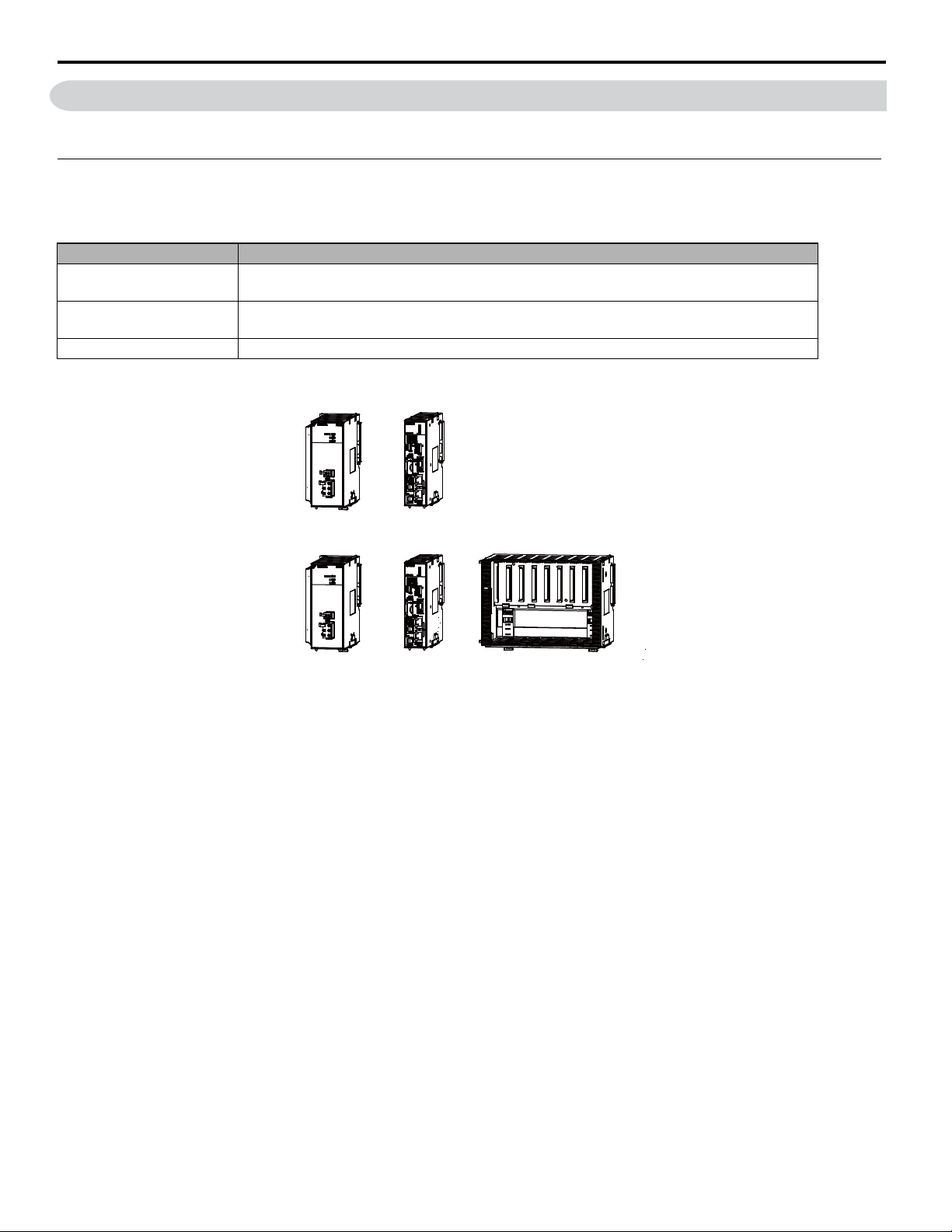
This section defines terms that have specific meanings in this manual.
Basic Units
“Basic Unit” is a collective term that refers to the three Units in the foll owing table.
Unit Name Primary Function
Power Supply Unit
CPU Unit
Base Unit Used to mount Optional Modules.
The Basic Units are typically connected as shown in the following examples.
Supplies the power that is needed for the operation of the Units that are connected to each other and to
any Optional Modules that ar e conn ect ed in the Contro ller.
Stores the module definitions and programs, and interprets the programs. The CPU Unit also controls
the Optional Modules.
1 Definition of Terms
YASKAWA America, Inc. MP3200iec Hardware Manual YAI-SIA-IEC-5 5
Page 8
2 System Configuration Example
2 System Configuration Example
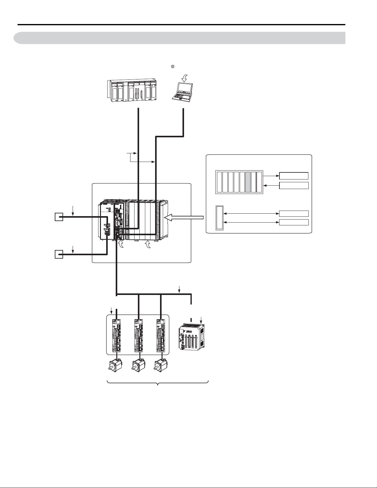
The following figure shows a typical system configuration.
MotionWorks IEC version
2.4 or higher
Ethernet communications cables
MP3200iec
RLYOUT
components
connector cable
24-VDC power
supply, AC power
supply, or status
monitoring device
Power supply cable
24-VDC power
supply or AC
power supply
Another PLC
Ethernet
Battery
MECHATROLINK-III
Front cover
for unused slot
PC
Ethernet
MECHATROLINK-III Cable
Optional Modules
I/O Modules
IO-02
L
LIO-01
LIO-04
LIO-05
LIO-06
AI-01
DO-01
AO-01
Communications Modules
218IF-Y1
External outputs
External inputs
RS-232C
Ethernet
SERVOPACK with
MECHATROLINK-III
Communications
Servomotor
Servomotor
Servomotor
I/O Module with
MECHATROLINK-
Communications
I/O
III
Up to 62 stations, including I/O
6 YASKAWA America, Inc. MP3200iec Hardware Manual YAI-SIA-IEC-5
Page 9

3 Component Part Numbers
System Components
Type Part Number Description
PMC-U-MP32004 CPU, MP3200iec, 4 axis
PMC-U-MP32008 CPU, MP3200iec, 8 axis
CPU
Power Supply
Base Unit
Option Card
MECHATROLINK
Network
MECHATROLINK
Cables
Accessories
PMC-U-MP32016 CPU, MP3200iec, 16 axis
PMC-U-MP32032 CPU, MP3200iec, 32 axis
PMC-U-MP32062 CPU, MP3200iec, 62 axis
JEPMC-PSA3012-E POWER SUPPLY, 100V/200V, MP3200
JEPMC-PSD3012-E POWER SUPPLY, 24VDC, MP3200
JEPMC-BUB3003-E BASE UNIT, 3 SLOTS, MP3200
JEPMC-BUB3005-E BASE UNIT, 5 SLOTS, MP3200
JEPMC-BUB3008-E BASE UNIT, 8 SLOTS, MP3200
JAPMC-AN2300 Analog Inputs (AI-01)
JAPMC-AN2310-E Analog Outputs (AO-01)
JAPMC-DO2300 Digital Output Modu le (DO-01)
JAPMC-IO2300-E Digital I/O Module (LIO-01)
JAPMC-IO2301-E Digital I/O Module (LIO-02)
JAPMC-IO2303 Digital I/O Module (LIO-04)
JAPMC-IO2304 Digital I/O Module (LIO-05)
JAPMC-IO2305-E Digital Multi-Function I/O Module (LIO-06)
JAPMC-CM2301-E Ethernet & RS232C Communication (218IF-Y1)
JEPMC-MT2000-E HUB, MECHATROLINK-III NETWORK, 8 SLAVE PORTS
JEPMC-MT2020-E ADAPTER, ETHERNET TO MECHATROLINK
JEPMC-MTD2310-E I/O MODULE, MECHATROLINK NETWORK, 64 IN, 64 OUT
JEPMC-MTA2900-E ANALOG MODULE, MECHAT ROLINK NETWORK, 8 INPUT
JEPMC-MTA2910-E ANALOG MODULE, MECHATROLINK NETWORK, 4 OUTPUT
JEPMC-W6012-A2-E MECHATROLINK-III CABLE, 0.2 M
JEPMC-W6012-A5-E MECHATROLINK-III CABLE, 0.5 M
JEPMC-W6012-01-E MECHATROLINK-III CABLE, 1.0 M
JEPMC-W6012-02-E MECHATROLINK-III CABLE, 2.0 M
JEPMC-W6012-03-E MECHATROLINK-III CABLE, 3.0 M
JEPMC-W6012-04-E MECHATROLINK-III CABLE, 4.0 M
JEPMC-W6012-05-E MECHATROLINK-III CABLE, 5.0 M
JEPMC-W6012-10-E MECHATROLINK-III CABLE, 10 M
JEPMC-W6012-20-E MECHATROLINK-III CABLE, 20 M
JEPMC-W6012-30-E MECHATROLINK-III CABLE, 30 M
JEPMC-W6012-40-E MECHATROLINK-III CABLE, 40 M
JEPMC-W6012-50-E MECHATROLINK-III CABLE, 50 M
JEPMC-BA3001 Replacement Battery
JEPMC-OP2300 Option Slot Cover
JEPMC-OP3001 Replacement Power Supply Side Cover
JEPMC-OP3002 Replacement Option Base Side Cover
3 Component Part Numbers
YASKAWA America, Inc. MP3200iec Hardware Manual YAI-SIA-IEC-5 7
Page 10
4 Power Supply Units
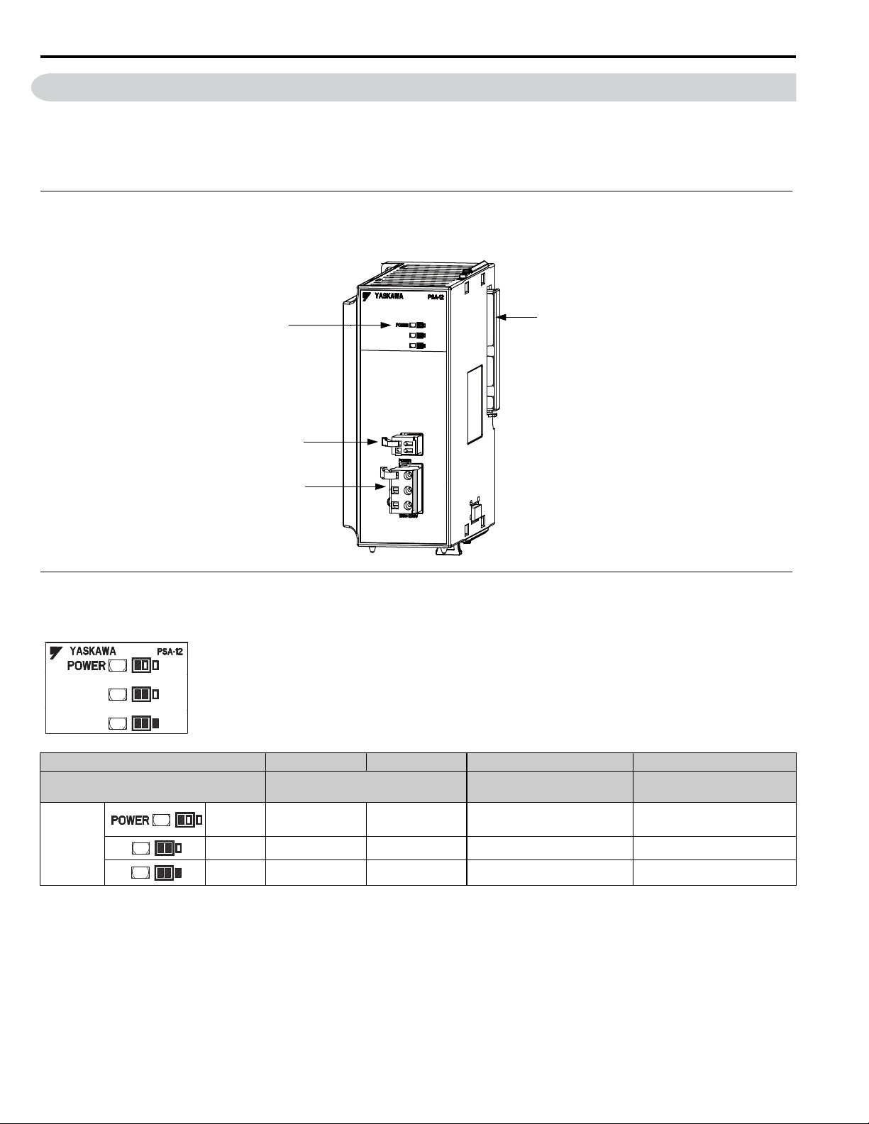
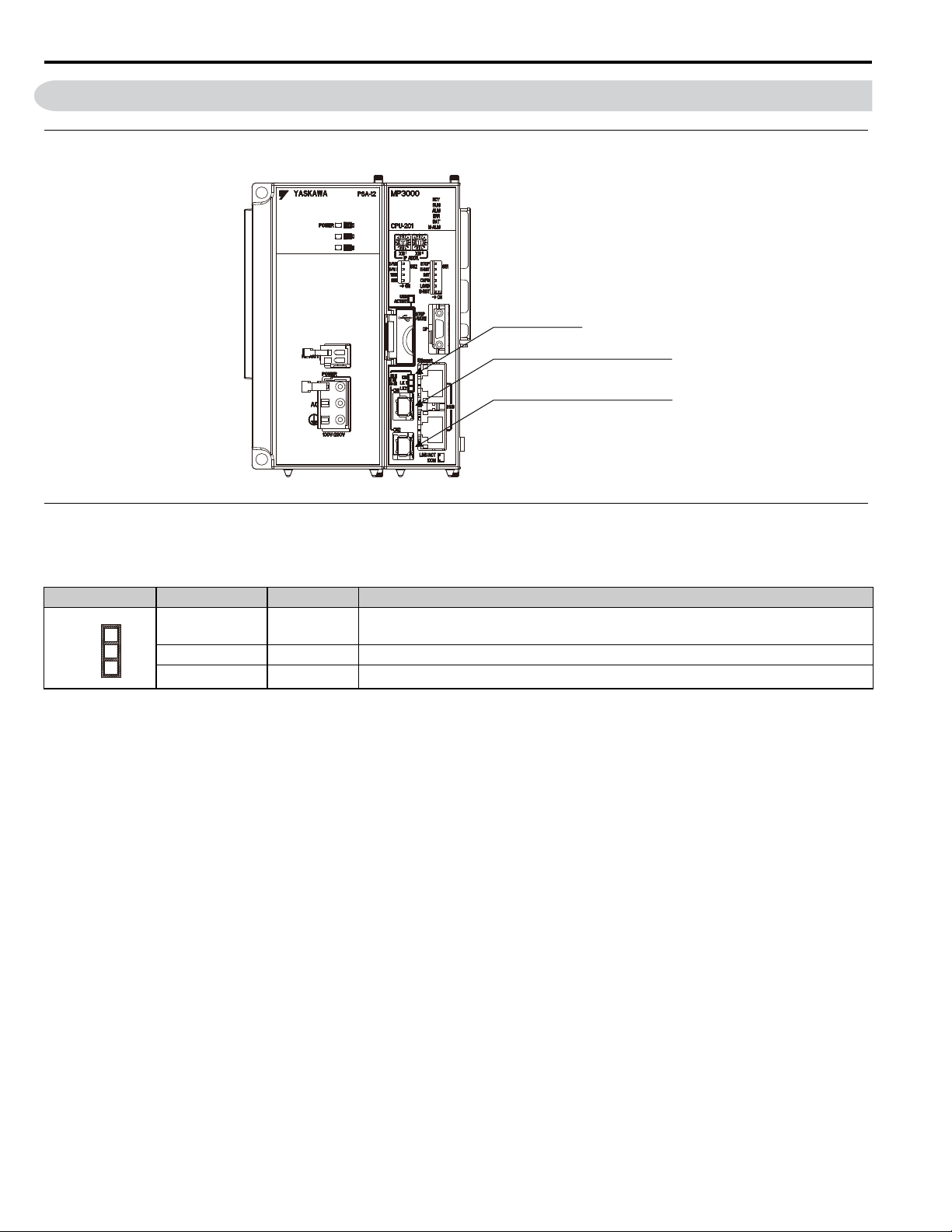
Indicators
RLYOUT connector
Power connector
Unit connector
4 Power Supply Uni ts
The Power Supply Unit supplies the connected Units and Optional Modules with the power needed to operate. There are
two Power Supply Units available: an AC Power Supply Unit and a DC Power Supply Unit.
This section shows the appearance and part names of the Power Supply Unit and describes the indicators and connectors.
Appearance and Part Names
The following figure shows the appearance of the Power Supply Unit and the part names.
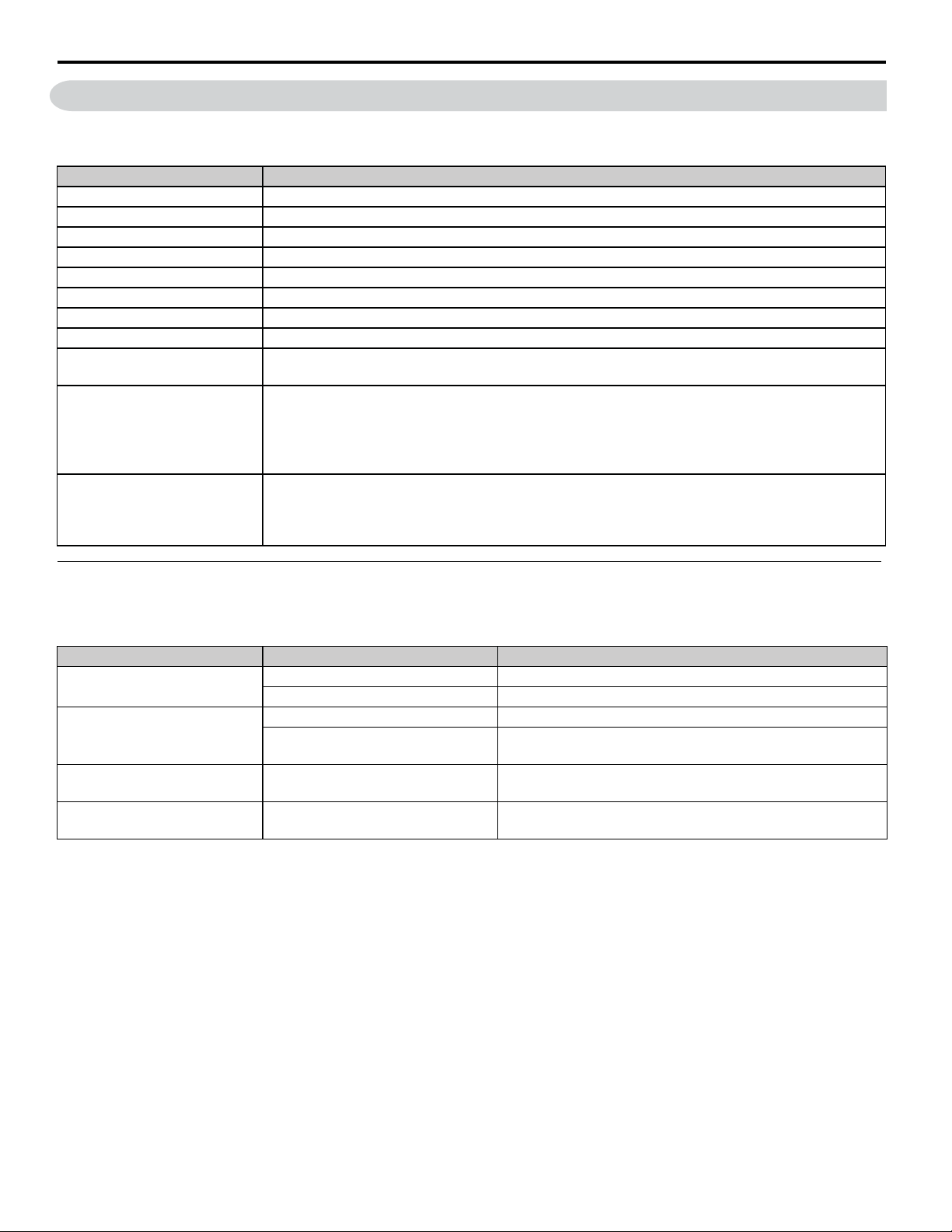
Indicators
These indicators show the load on the Power Supply Unit.
Output Current 8.9 A or less 9.0 to 11.4 A 11.5 to 13.9 A
Load
Green
Appendix
Indicator
<1> Reduce the number of Optional Mo dules that are connected.
Note: z: Lit, {: Not lit.
Yellow {z z {
Red {{ z {
Normal: Within power supply
capacity
zz z {
<1>
Normal: Maximum power
supply capacity
14.0 A or more
Error: Over power supply
capacity
<1>
8 YASKAWA America, Inc. MP3200iec Hardware Manual YAI-SIA-IEC-5
Page 11
Connectors
The Power Supply Unit has three connectors: RLYOUT, power supply, and Unit connectors.
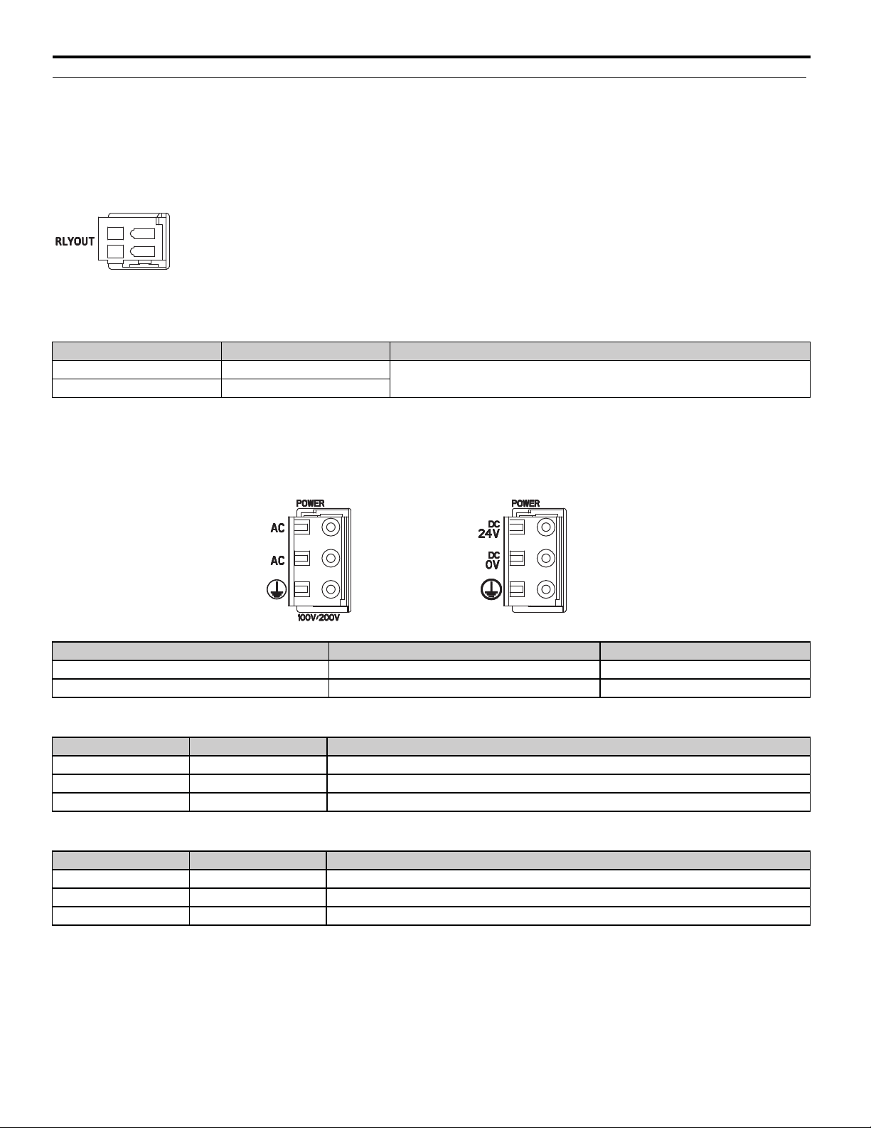
RLYOUT Connector
This connector outputs the operating status of the CPU Unit.
Model: 734-302
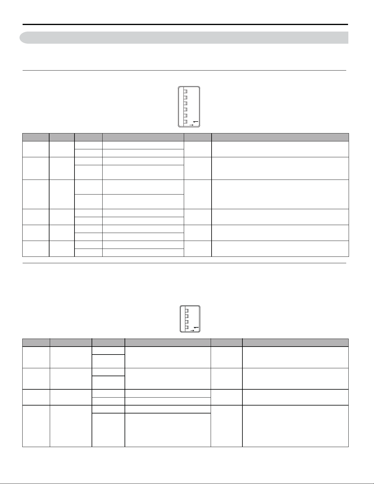
Pin Assignme n ts
No. Signal Label Description
1 OUT
2 OUT
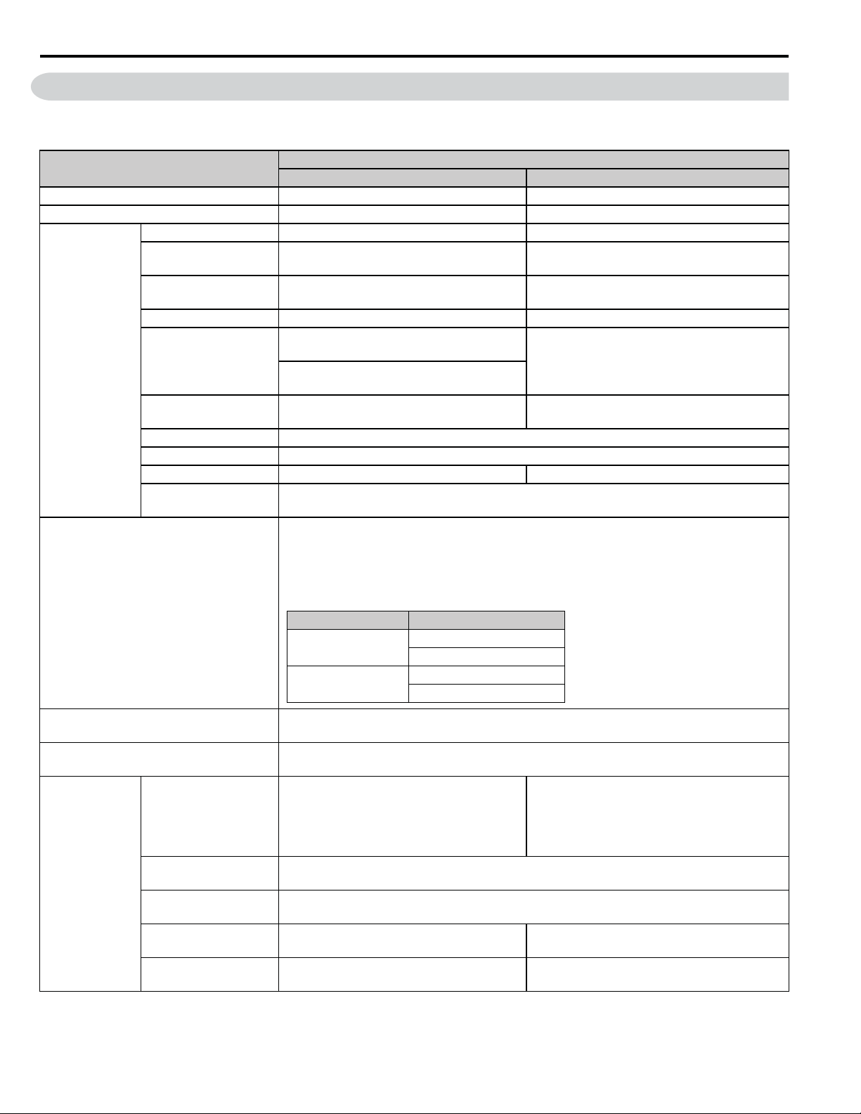
Power Connector
Normal operation: Circuit closed.
Error: Circuit open.
Connect the power supply to this connector.
4 Power Supply Units
Type Model Color
AC Power Supply Unit 721-203/026-304 Black
DC Power Supply Unit 721-203/026-000 White
Pin Assignments: AC Power Supply Unit
Pin No. Signal Label Description
3AC AC input
2AC AC input
1 FG Connects to the frame ground. (Ground to 100 W max.)
Pin Assignments: DC Power Supply Unit
Pin No. Signal Label Description
3 24 VDC Power input wire for 24 VDC
2 0 VDC Power input wire for 0 VDC
1 FG Connects to the frame gro und. (Ground to 100 W max.)
DC Power Supply UnitAC Power Supply Unit
YASKAWA America, Inc. MP3200iec Hardware Manual YAI-SIA-IEC-5 9
Page 12
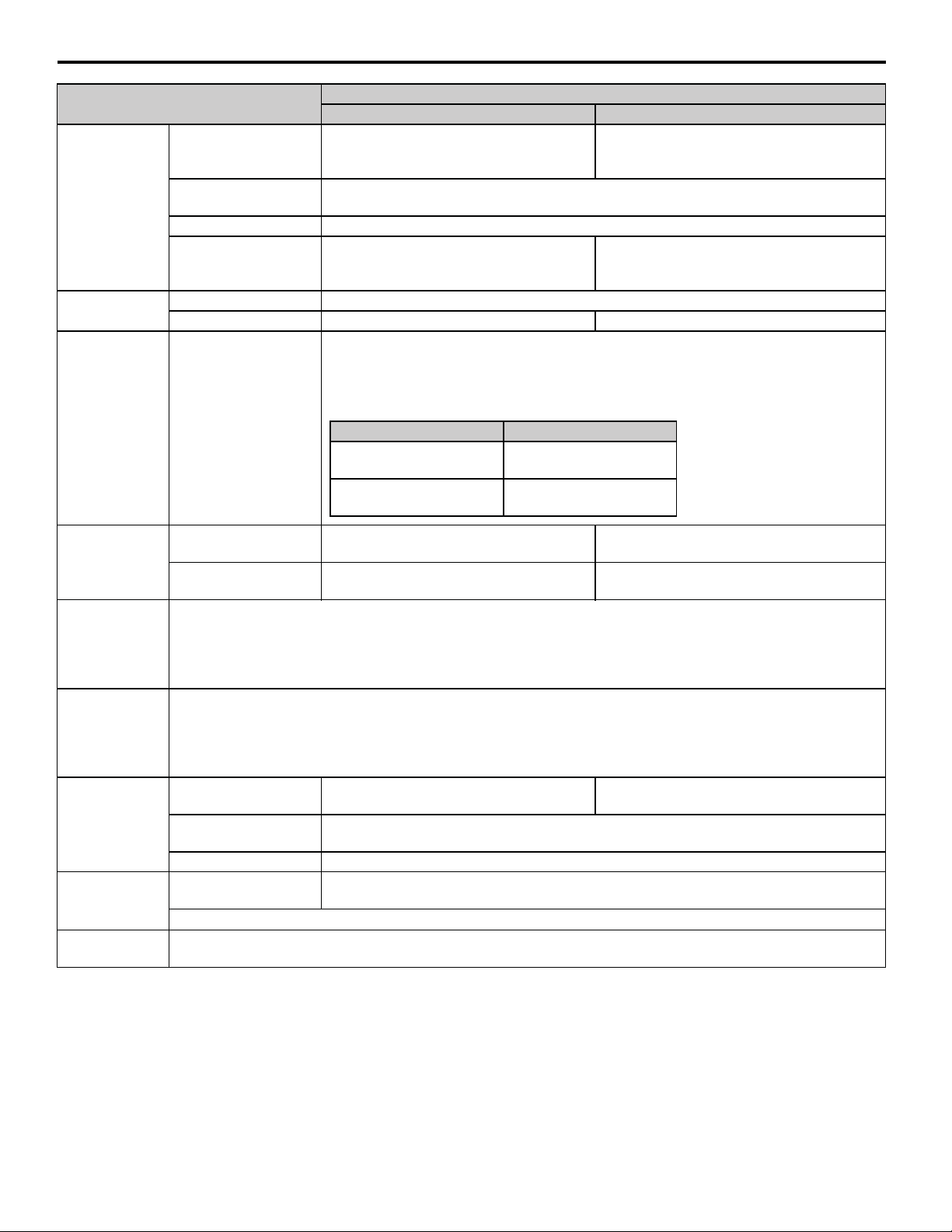
5 Power Supply Unit Specifications
5 Power Supply Unit Specifications
The specifications of the Power Supply Unit are given in the following table.
Item
Model JEPMC-PSA3012-E JEPMC-PSD3012-E
Abbreviation PSA-12 PSD-12
Input Voltage 100/200 VAC 24 VDC
Power Supply
Section
Allowable Input Voltage
Range
Allowable Frequency
Range
Input Current 4.0 A max. (at rated input/output) 5.0 A max. (at rated input/output)
Inrush Current
Allowable Momentary
Power Loss Time
Rated Voltage 5.15 V
Rated Current 12.0 A
Output Current Range 0 to 12.0 A 0.2 to 12.0 A
Constant Voltage
Accuracy
85 to 132 VAC or 170 to 276 VAC 19.2 to 28.8 VDC
47 to 63 Hz -
25 A, 10 ms max. (fully discharged, 132-VAC
input, rated output)
50 A, 10 ms max. (fully discharged, 276-VAC
input, rated output)
20 ms 1 ms
5.15 V ±2% max. (5.05 t o 5.25 V)
If the Power Supply Unit is mounted on the Main Rack, this output functions as normally closed
contacts that are synchronized with the status of the CPU Unit.
• Normal operation: Circuit closed.
• Error: Circuit open.
Contact Ratings
AC Power Supply Unit DC Power Supply Unit
Specification
50 A, 10 ms max. (fully discharged,
28.8-VDC input, rated output)
Status Output
Connectors
Indicators
Input Conditions
Inrush Current
Rise Time
Drop Time
Leakage Current
Efficiency
Input Voltage Current Capacity
24 VDC
125 VAC
POWER: Power supply connector
RLY OUT: Relay contact connector
POWER
Refer to Indicators on page 12.
For Cold Start
50 A within 10 ms (fully discharged status)
275-VAC input, rated output
60,000 ms max. (The maximum time for the output control signals to maintain the specified timing
when the primary voltage rises linearly.)
60,000 ms max. (The maximum time that the controls, such as the power failure sequence, can be
maintained when the primary voltage drops linearly.)
276 VAC 61 Hz: 0.5 mA max.
132 VAC 61 Hz: 0.25 mA max.
70% minimum (for rated input voltage and
rated load)
0.5 A (resistive load)
0.25 A (inductive l oad)
0.4 A (resistive load)
0.2 A (inductive load)
For Cold Start
(Through rate at input voltage value increase from
10% to 90% is at 10 ms min.)
50 A within 10 ms (fully discharged status)
28.8-VDC input, rated output
65% minimum (for rat e d input voltage and ra ted
load)
10 YASKAWA America, Inc. MP3200iec Hardware Manual YAI-SIA-IEC-5
Page 13
5 Power Supply Unit Specifications
Protection
Safety
Status
Output
Power Sequences
Dielectric
Strength
Insulation
Resistance
(Measured at
500 VDC.)
External Wiring
Connector
Terminals
Connector Cable
Hot
Swapping
Item
AC Power Supply Unit DC Power Supply Unit
Specification
Low Input Protection
(Power Fail Detection
55 to 75 VAC or 150 VAC max. 15.8 to 17.8 VDC
Level)
Overcurrent Protection
For rated curren t (12 A), the protection operates at 14.0 A min. (typical).
(The detection range is 13.0 to 15.0 A.)
Overvoltage Protection Operates at 5.75 to 6.75 V.
Allowable Power Loss
Time
The output voltage fluctuation range is
maintained for a 20-ms 100% dip momenta ry
power loss.
The output voltage fluctuatio n range is ma intained
for a 1-ms 100% dip momentary power loss.
Safety Standards Conforms to UL and CSA.
Fuse 250 V/4 A 250 V/6.3 A
Linked to the RDY indicator on the CPU Un it.
RDY indicator lit: Circuit closed.
RDY indicator not lit: Circuit open.
Contact Ratings
NO Contact Output (RLY
OUT)
Power ON
Power OFF
Input Voltage Current Capacity
24 VDC
125 VAC
0.5 A (resistive load)
0.25 A (inductive load)
0.4 A (resistive load)
0.2 A (inductive load)
AC ON - 5-V rise in 1 s max.
Output rise - POK signal in 0 s min.
AC OFF - POK signal for 20 ms min.
POK signal - 5-V drop in 2 ms min.
DC ON - 5-V rise in 1 s max.
Output rise - POK signal in 0 s min.
DC OFF - POK signal for 1 ms min.
POK signal - 5-V drop in 2 ms min.
Between primary and secondary sides: 1,500 VAC for 1 minute
Between primary side and FG (ground): 1,500 VAC for 1 minute
Between secondary s ide and FG (ground): 50 0 VAC for 1 minute
Between RLYOUT and primary side: 1,500 VAC for 1 minute
Between RLYOUT and secondary side: 1,500 VAC for 1 minute
Between primary and secondary sides: 10 MΩ min .
Between primary side and FG (ground): 10 MΩ min.
Between secondary s ide and FG (ground): 100 MΩ min.
Between RLYOUT and primary side: 100 MΩ min.
Between RLYOUT and secondary side: 100 MΩ min.
External Power Supply
Terminals
Protective Ground
Terminal
AC, AC 0 and 24 VDC
FG
RLY OUT RLYOUT
External Power Supply
Terminals (Twisted Pair)
AWG28 to AWG13 (0.08 to 2.6 mm
2
)
RLY OUT Connector Cable: AWG28 to AWG14 (0.08 to 2.0 mm2)
Not supported.
YASKAWA America, Inc. MP3200iec Hardware Manual YAI-SIA-IEC-5 11
Page 14
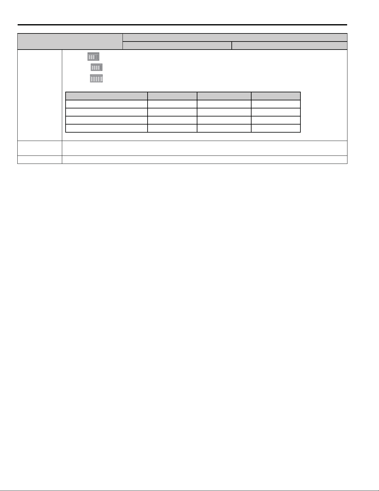
5 Power Supply Unit Specifications
Output Current (iout (typical)) POWER (Green) (No Label) (Yellow) (No Label) (Red)
i out ≤ 8.9 A z{{
9.0 A ≤ iout ≤ 11.4 A zz{
11.5 A ≤ iou t ≤ 13 .9 A zzz
14.0 A ≤ iout (OCP activation) {{{
Item
POWER (green): Lights when the power is ON on the secondary side.
(No label) (yellow): Lights when the Overcurrent Warning 1 Status Output is ON.
(No label) (red): Lights when the Overcurrent Warning 2 Status Output is ON.
Indicators
z: Lit {: Not lit.
External
Dimensions
Weight 350 g
Width: 60 mm, Height: 130 mm, De pth: 137 mm
Specification
AC Power Supply Unit DC Power Supply Unit
12 YASKAWA America, Inc. MP3200iec Hardware Manual YAI-SIA-IEC-5
Page 15
6 CPU Specifications
6 CPU Specifications
The hardware specifications of the CPU Unit are given in the following table.
Item Specification
Model PMC-U-MP320xx
Abbreviation MP3200iec
Flash Memory Capacity: 40 MB (32 MB of user memory)
SDRAM Capacity: 128 MB
SRAM Capa city: 8 MB (ba ttery ba c kup)
Calendar Seconds, minutes, hour, day, week, month, year, day of week, and timing (battery backup)
Ethernet 10Base-T or 100Base-TX x 2 ports (hub)
MECHATROLINK MECHATROLINK-III: 1 circuit with 2 ports
USB
Indicators and D i s plays
Switches
USB 2.0 Type A host, 1 port
Compatible devices: USB storage
Seven-segment display
Status indicators
USB status indicator
MECHATROLINK-III status indicators
Ethernet status indicators
DIP switch: Mode switch 1
DIP switch: Mode switch 2
Rotary switches
STOP/SAVE switch. Refer to DIP Switch Settings on page 27 for detailed switch information.
CPU Communications Specifications
The specifications of th e Communications Protocols built into the CPU Unit are given in the following table.
Protocol Mode Detail
Modbus TCP
Ethernet/IP
OPC read/write
Custom Protocol n/a
MP3200iec as Master (Client) Maximum Number of Data Blocks = 20
MP3200iec as Slave (Server) 1000 registers in, 1000 registers out, 256 coils in, 256 coils out
MP3200iec as Master (Scanner) Maximum Number of Data Blocks = 100
MP3200iec as Slave (Adapter)
Total 16 instances in, 16 instances out, arranged as 3 instances of 256
bytes, 3 instances of 128 bytes, and 10 inst ances of 496 bytes.
Any Global variable can be configured, requires OPC Server running
on PC
Use the YDeviceComm firmware library to cre ate a custom
communication pro tocol.
YASKAWA America, Inc. MP3200iec Hardware Manual YAI-SIA-IEC-5 13
Page 16
7 CPU External Appearance and Indicators
7 CPU External Appearance and Indicators
External Appearance
Indicators (LEDs)
MECHATROLINK-III connector CN1
MECHATROLINK-III connector CN2
Indicators
The following table describes the indicators that show the operating status and error information.
Indicator Indicator Name Color Meaning When Lit
MECHATROLINK-III communications are established as a slave (i.e., the CONNECT
command is ON).
CN
LK1
LK2
CN Green
LK1 Green Port 1 is performing MECHATROLINK-III communications.
LK2 Green Port 2 is performing MECHATROLINK-III communications.
14 YASKAWA America, Inc. MP3200iec Hardware Manual YAI-SIA-IEC-5
Page 17
8 Base Unit Installation and Operating Conditions
8 Base Unit Installation and Operating Conditions
This section describes the specifications of the MP3200iec Series Machine Controllers.
Install the MP3200iec Series Controllers in an environment with the following conditions.
Environmental Conditions
Item Specification
Ambient Operating Temperature 0 to 55°C (CPU-03: 0 to 50°C)
Ambient Storage Temperature -25 to 85°C
Ambient Operating Humidity 30% to 95% RH (with no condensation)
Ambient Storage Humidity 5% to 95% RH (with no condensation)
Pollution Degree Conforms to JIS B 3502 Pollution Degree 2.
Corrosive Gases There must be no combustible or corrosive gases.
Operating Altitude 2,000 m max.
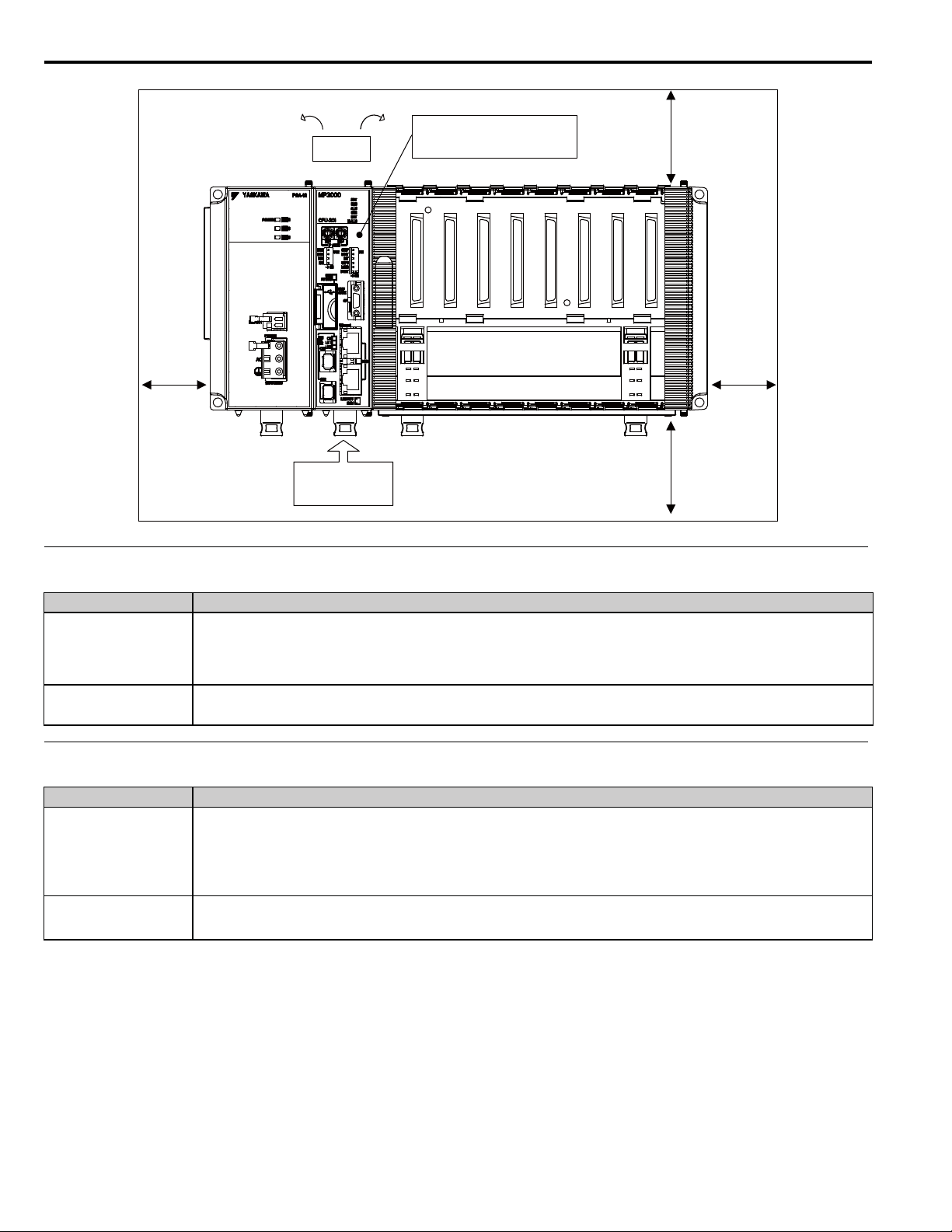
Control Panel Cooling Method
The components that are used in the Machine Controller require the ambient operating temperature to be between 0 and
55°C. Use one of the methods described below to ensure adequate cooling in the control panel.
Note: If the ambient temperature exceeds 50°C, we recommend forced-ai r cooling.
Control Panels with Natural Cooling
• Do not mount the Machine Controller at the top of the control panel, where th e hot air that is genera ted inside the panel
collects.
• Leave sufficient spac e above and below the Units , and maintain ade quate dist ances from oth er devices, ca ble ducts, and
other objects to ensure suitable air circulation.
• Do not mount the Controller in any direction other than the specified direction.
• Do not mount the Controller on top of any device that generates a significant amount of heat.
• Do not subject the Controller to direct sunlight.
Control Panels with Forced-air Cooling
Use one of the following methods to ensure 0.03 m3/min average airflow below the CP U Unit.
• Forced draft method (A fan or a similar device is used to circulate the air in the interior and the exterior of the panel.)
• Forced circulation method (A fan or a similar device is mounted to the airtight panel to circulate the air inside.)
Note: Use the following guideline when selecting the fan: CPU Unit’s resistance to air flow: 6 x 10⁶ (N×s2/m8)
YASKAWA America, Inc. MP3200iec Hardware Manual YAI-SIA-IEC-5 15
Page 18
8 Base Unit Installation and Operating Conditions
Fan
CPU Unit’s internal resistance to
air flow: 6×10
6
(N⋅s2/m8)
40 mm min.
30 mm min.
Average airflow:
0.03 m
Mechanical Operating Conditions
Item Specification
Conforms to JIS B 3502.
Vibration Resistance
10 Hz ≤ f < 57 Hz with vibration amplitude of 0.075 mm
57 Hz ≤ f ≤ 150 Hz with fixed acceleration of 9.8 m/s
10 sweeps each in X, Y, Z directions (sweep: 1 octave/min)
Shock Resist ance
Electrical Operating Conditions
Conforms to JIS B 3502.
Peak acceleration of 147 m/s
Item Specification
Conforms to EN 61000-6- 2 and EN 55011 (Group 1 Class A).
Power supply noise (FT noise): 2 kV min. for 1 minute
Noise Resistance
Radiation noise (FT noise): 1 kV min., for 1 minute
Ground noise (impul se noise): ±1 kV min., for 10 minutes
Electrostatic noise (conducted): ±4 kV min ., 10 times
3
/min
2
2
twice for 11 ms each in the X, Y, and Z directions
30 mm min.
40 mm min.
Ground Information Ground to 100
ȍ
max.
16 YASKAWA America, Inc. MP3200iec Hardware Manual YAI-SIA-IEC-5
Page 19
9 Installation
Screw Mounting Attachment
You can use either of the following methods to install an MP3200iec Series Controller.
•Screw mounting
• DIN rail mounting
Screw Mounting
You can install the Unit by using the Screw Mounting Attachment.
Note: You can install the Unit by using the Screw Mounting Attachment.
• JEPMC-OP3001
This Attachment is provided with the Power Supply Unit. It can be installed on the PMC-U-MP320**.
• JEPMC-OP3002
This Attachment is provided with the MBU-B03, MBU-B05, and MBU-B08. It can be purchased separately.
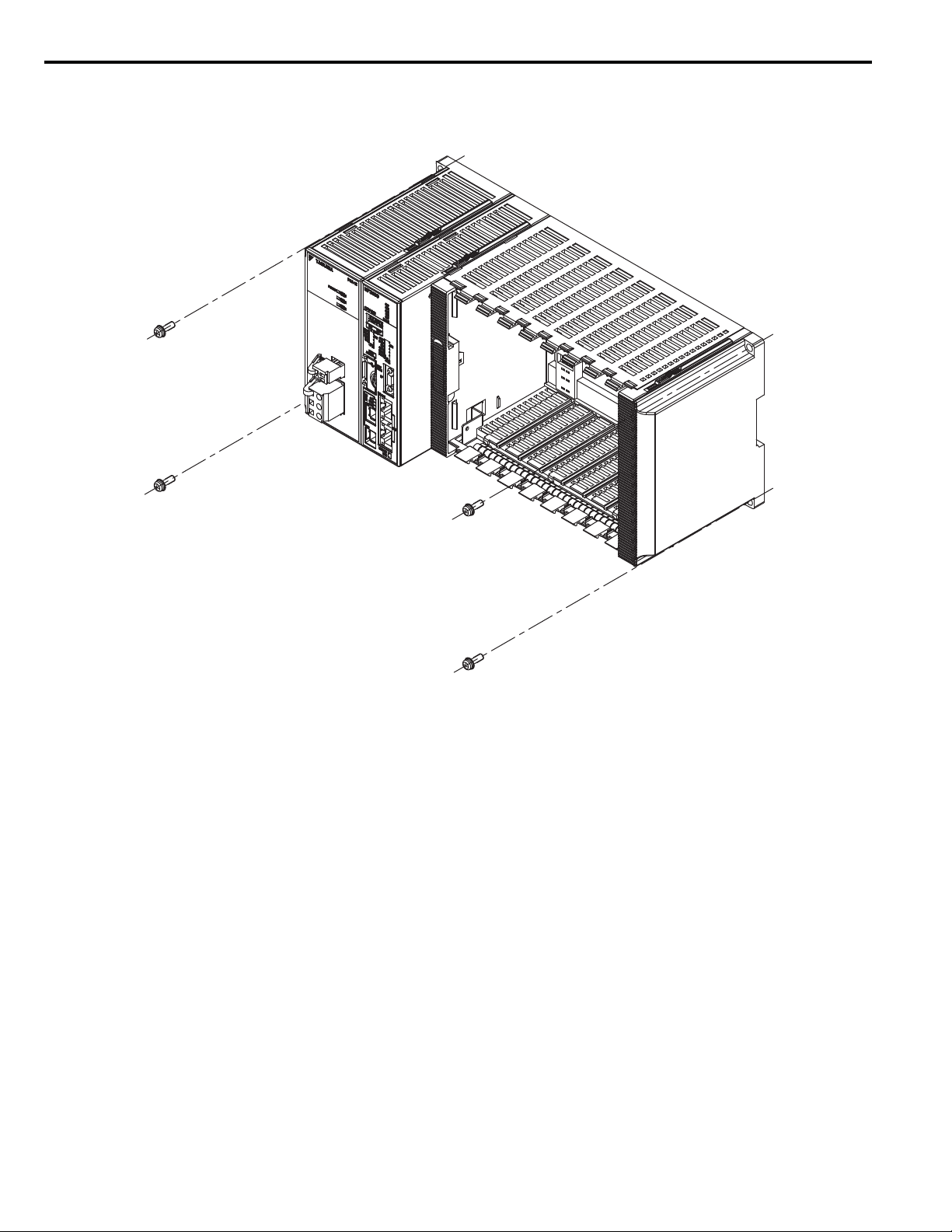
The installation procedure is as follows:
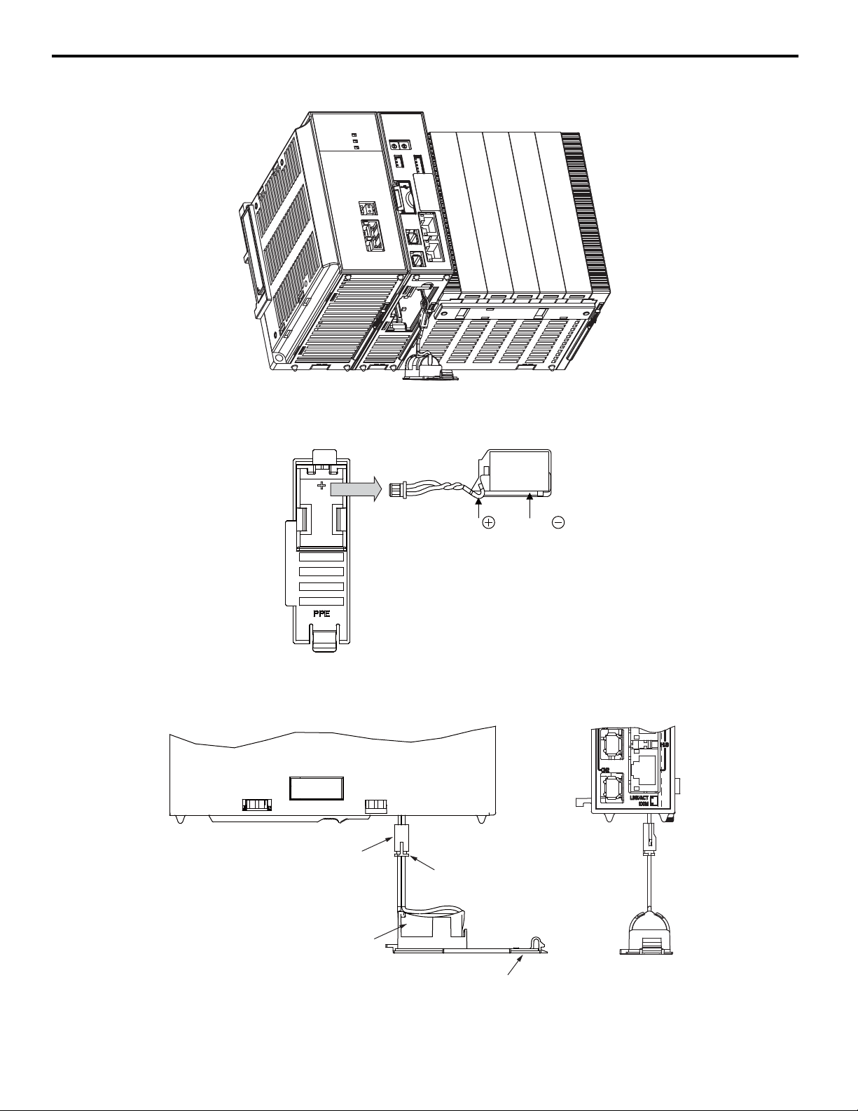
1. Attach the Screw Mounting Attachment to the right end of the Controller.
9 Installation
YASKAWA America, Inc. MP3200iec Hardware Manual YAI-SIA-IEC-5 17
Page 20
9 Installation
2. Use screws to secure the 4 places shown in the following figure.
Note: 1. Recommended screws: M4 x 14 mm min.
2. Use a screwdriver wit h a shaft that is at least 13 cm long.
18 YASKAWA America, Inc. MP3200iec Hardware Manual YAI-SIA-IEC-5
Page 21
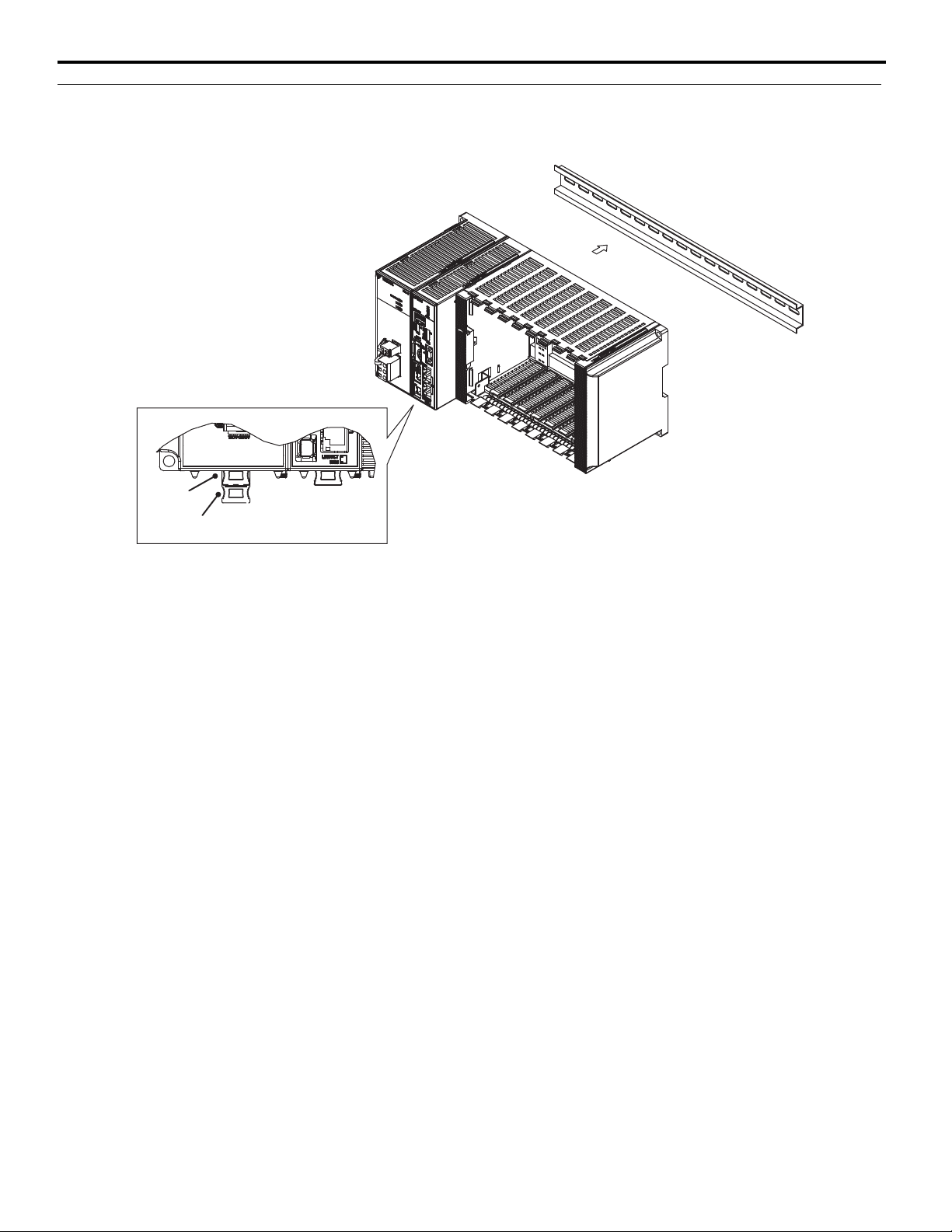
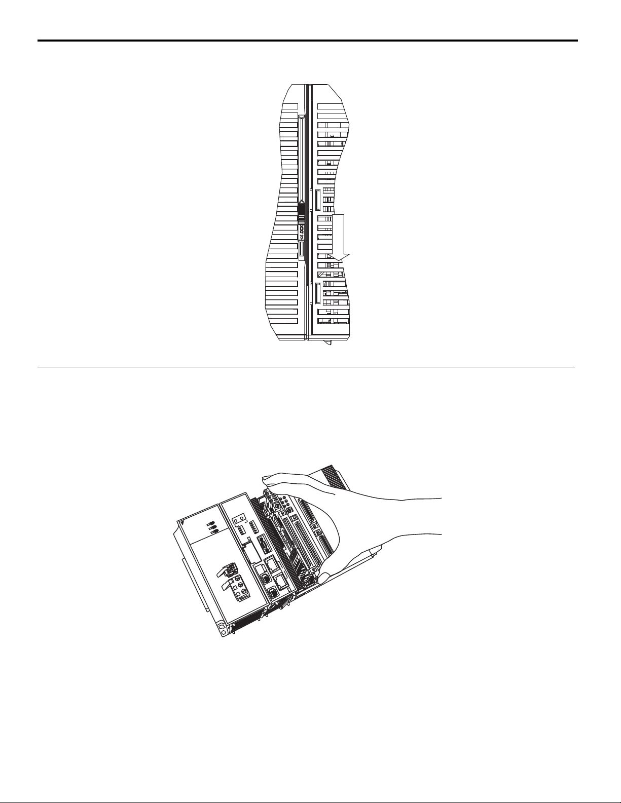
Lock release position
Locking position
DIN Rail Mounting
Carefully line up the DIN rail locks wit h the locking positions.
9 Installation
Note: Removal
You can remove t he Controller by revers ing the order of the mo unting procedure.
YASKAWA America, Inc. MP3200iec Hardware Manual YAI-SIA-IEC-5 19
Page 22
9 Installation
Connecting the CPU
Note: Before you connect the CPU, install the Battery. Refer to Installing and Replacing the Battery in the CPU on page 24.
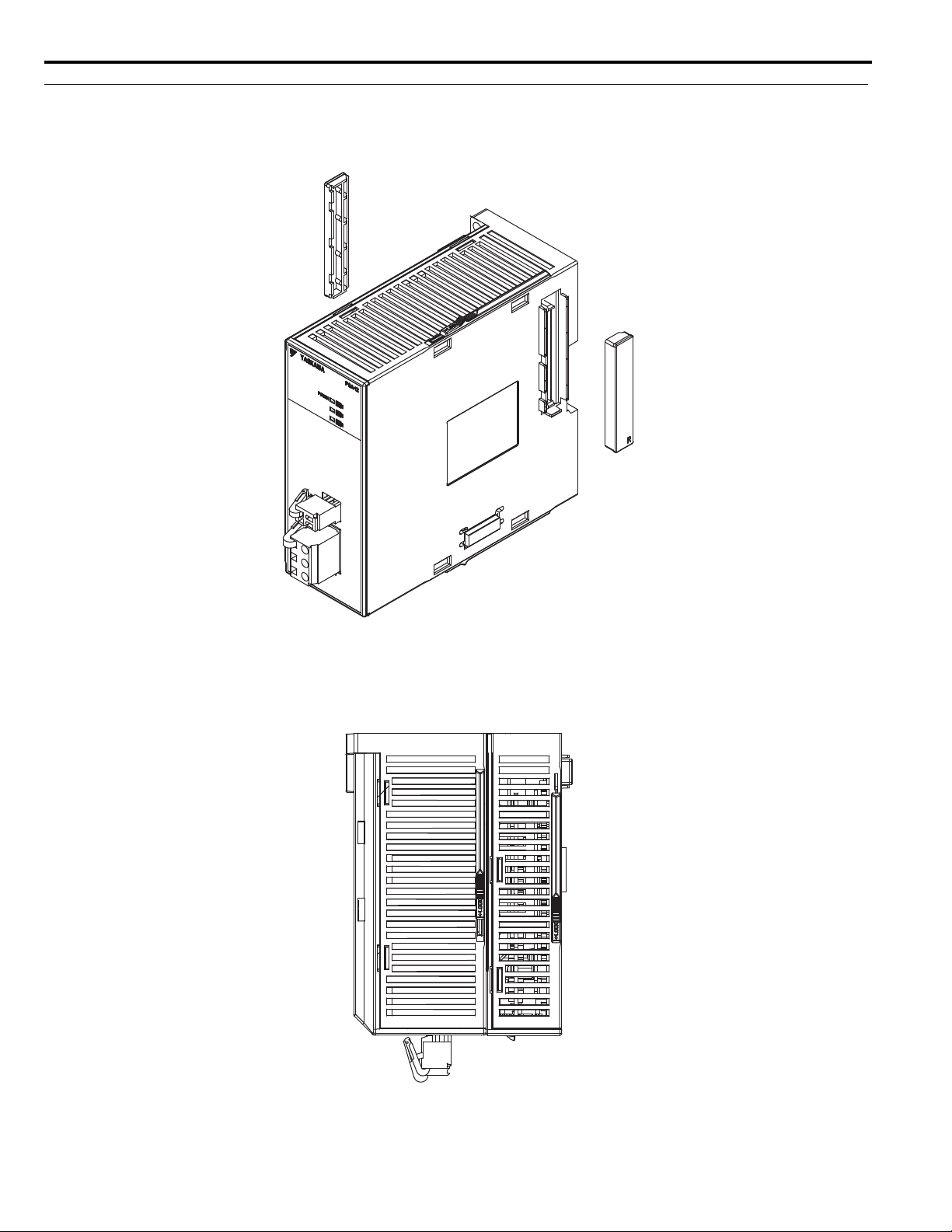
1. Remove the rubber cap from the connector on the Power Supply Unit.
Note:
• When the connector is not in use, always cover it with the rubber cap.
• The left-side cap is marked with an L, and the right-side cap is marked with an R.
2. Connect the Power Supply Unit and the CPU Unit from left to right in this order.
20 YASKAWA America, Inc. MP3200iec Hardware Manual YAI-SIA-IEC-5
Page 23
3. Secure the connection by locking the slide locks at both the top and the bottom.
4
.;176
.
;17
6
;
#5-#9##5-#9#
/22
2
5#5#
%2727
2
19'41
9
'
4
#
%
&
#
%
&
4
&;&
;
4704
70
#./#
.
/
'44'4
4
$#6$
#6
/#.//
#
.
/
+
2#&&42
#
&
&
4
:
:
'2/
2/
'2/'2/
6'566'56
/06
5
99
5
9
9
.
&&
.
&
&
+
11
1
0
ψ
10
1
0
5
6126
1
2
'+0+6'
+
0
+
6
+0+6+
0
+
6
%0()%
0
(
)
.1#&.
1
#
&
&456&
4
5
6
7
5$5
$
#%6+8'#
%
6
+
8
'
5
6126
1
2
5#8'
5
#
8
'
%
0
.-
.
-
.-.
-
%
.+0-#%6.
+
0
-
#
%6
/
/
%
00
%
00
'
VJGTPGVV
J
G
T
P
G
V
*
7$7
$
1
2
/
+++
+
+
+
9 Installation
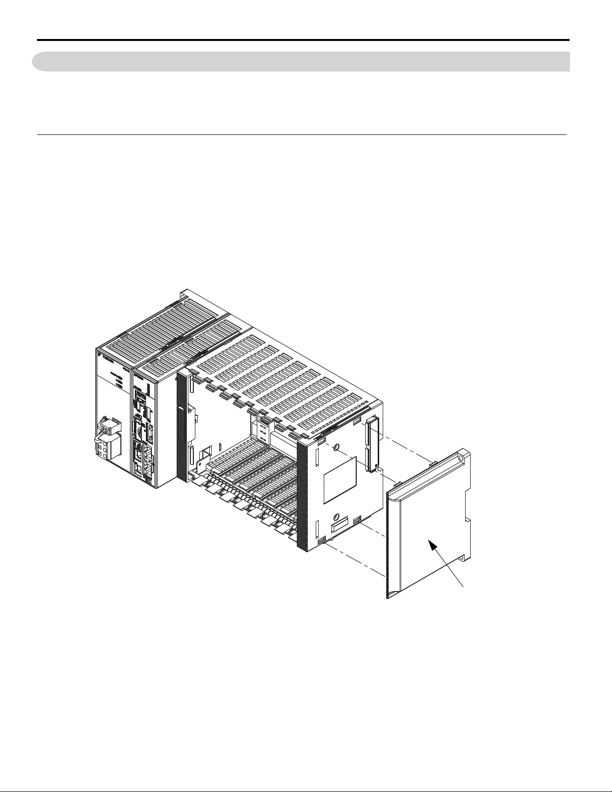
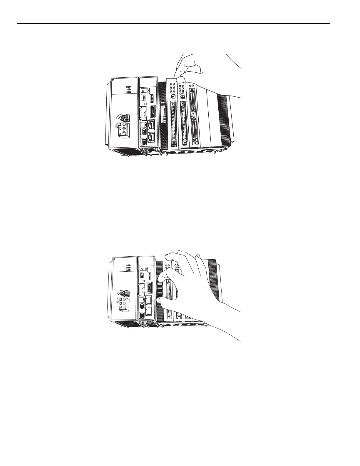
Installing Optional Modules
Use the following procedure to install Optional Modules.
1. Hold the top and bottom of the Optional Module to be installed, line up the Module with the left side of the guide rail
inside the option slot, and then insert the Module straight in.
Note: The FG bar inside and on the bottom may be damaged if the Module is not inserted along the guide rail.
2. After the Optional Module is completely inserted, place your hand on the front of the Optional Module and press the
Optional Module firmly until it mates with the Mounting Base connectors in the Unit. The front of the Optional
Module and the tabs will be aligned if the Optional Module has been installed properly.
YASKAWA America, Inc. MP3200iec Hardware Manual YAI-SIA-IEC-5 21
Page 24
9 Installation
;
#
5
-
#
9
#
2
5
#
2
19'4
88
/
2
%
2
7
:
+
2
#
&
&
4
'
2
/
'
2
/
6
'
5
6
/
0
6
5
6
12
'+
0+6
+0
+6
%0
()
.1#&
&45
6
75$
#
%6+8
'
5
612
5
#8'
12
'
V
J
G
T
P
G
V
%
0
%
0
%0
.
-
.
-
:
5
9
5
9
1
0
ψ
1
0
4
&
;
4
7
0
#
.
/
'
4
4
$
#
6
/
#
.
/
#
%
&
#
%
&
.
&
.
&
.
&
.
&
.
&
.
&
.
&
.
&
.
&
4
70
(
.
&
%
0
.
&
.
&
.
&
.
&
.&
.
&
/
1&'
.
+
1
+
%
0
*
7$
;#5-#9#
25#
219'4
88
/2
%27
:
+2#&&4
'2/
'2/
6'56
/06
5612
'+0+6
+0+6
%0()
.1#&
&456
75$
#%6+8'
5612
5#8'
12
'VJGTPGV
%0
%0
%0
%0
.-
.-
:
59
59
10
ψ10
4&;
470
#./
'44
$#6
/#./
#
%
&
#
%
&
.&
.&
.&
.+1
.+1
.&
.&
.&
.&
.&
.&
*7$
3. Place the hole on the bottom of the panel of the Optional Module onto the tab on the bottom of the Unit. Next, hook the
hole at the top of the panel of the Optional Module onto the tab on the Unit.
5#
2
&;
#5-#9#
19'4
88
470
#./
'44
$#6
/#./
27
2#&&4
612
2/
9
'+0+6
'2/
+0+6
6'56
%0()
/06
.1#&
&456
10
ψ
#%6+8'
612
5#8'
VJGTPGV
-
-
0
+1
&
&
&
&
&
&
&
&
9
7$
&
70
&
0
&
&
&
&
&
1&'
0
This completes the installation proce dure.
Note: Always use Option Covers (model: JEPMC-OP2300) to c over unused slots.
Replacing and Adding Optional Modules
Use the following procedure to replace or add Optional Modules.
Note: Always create a backup before replacing o r adding Optional Mo dules.
Use the Web Server to save the Application program image as an Archive.Zip.
1. Turn OFF the power supply and disconnect all cables from the MP3200iec.
2. Remove the tool from Base Unit.
22 YASKAWA America, Inc. MP3200iec Hardware Manual YAI-SIA-IEC-5
Page 25
9 Installation
;
#5-#9##
5
-
#9
#
2
5#5
#
2
19'41
9
'
4
88
8
8
/
22
%
272
7
:
+
2#&&42
#
&
&
4
'
2/
2
/
'2/'
2
/
6'566
'
5
6
/06/
0
6
5
6126
1
2
'+0+6'
+
0
+
6
+0+6+
0
+
6
%0()%0
(
)
.1#&.
1
#
&
&456&
4
5
6
75$5$
#%6+8'#%6+8'
5612612
5#8'5#8
'
12
*
7$7$
'VJGTPGVVJGT
PGV
%0
%
00
%
0
0
%00
.--
.--
:
5
99
5
99
1
0
1
0
4
&;&
;
4704
7
0
#./#
.
/
'44'
4
4
$#6$
#
6
/#.//
#
.
/
#
%
&
#
%
&
.+1+
1
.+1
+1
.
&&
.
&&
.
&&
.
&&
/
1&'
1
&
'
+
1
1
.
&&
.
&&
.
&&
.
&&
4
707
0
(
7
%
00
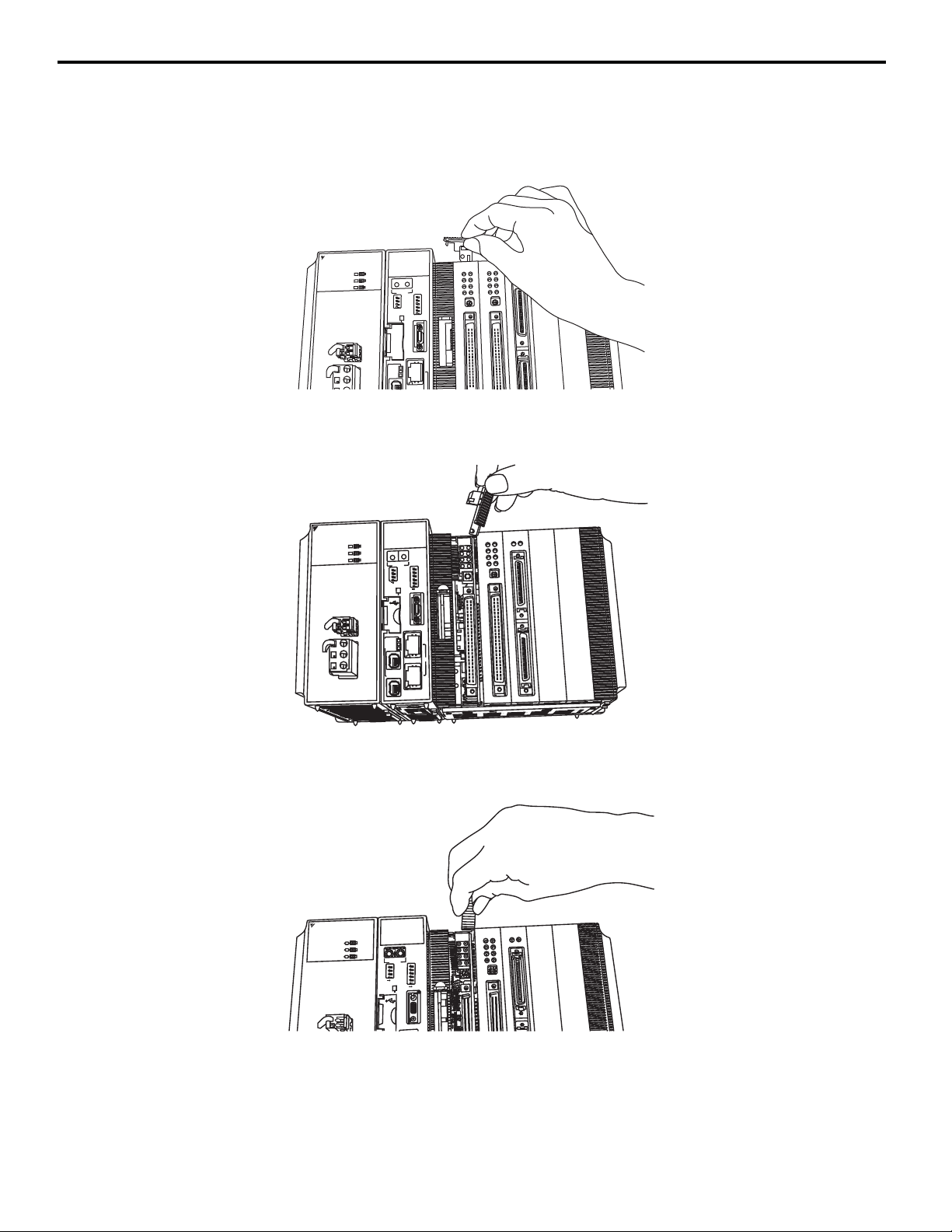
3. Insert the protruding part of the tool into the slot on top of the Optional Module panel to unhook the tab.
Unhook the bottom tab in the same way.
NOTICE: Use the same method to remove the Option Cover from an unused slot before adding an Optional Module.
25#
;#5-#9#
4.;1
/2
4&;
470
219'4
#
#
$
$
%
%
:
:
+2#&&4
5612
'2/
59
59
'+0+6
'2/
+0+6
6'56
%0()
/06
.1#&
10
&456
75$
ψ10
#%6+8'
5612
5#8'
12
'VJGTPGV
%0
.-
/+++
.-
%0
#./
'44
$#6
/#./
%27
.+1
.&
.&
.&
.&
/1&'
.+1
.&
.&
.&
.&
.&
.&
.&
.&
.&
.&
.&
.&
/1&'
+1
+1
4. Pull the top of the Optional Module panel toward you and remove it. A notch on the Optional Module will be visible
from the gap of the panel. Hook the round knob on the tool into the notch in the Optional Module.
5. Hold the center of the tool, and turn it around the round knob while pushing it toward the back to disconnect the
Module from the Mounting Base connectors. Then, pull the Module forward.
25#
/2
;#5-#9#
219'4
YASKAWA America, Inc. MP3200iec Hardware Manual YAI-SIA-IEC-5 23
0&;&
4&;
470
#./
'44
$#6
/#./
%27
:
:
+2#&&4
612
5
'
+0+6
59
59
'+0+6
'
+0+6
+0+6
6
'56
%0()
/
06
.1#&
1
0
&456
1
0
7
5$
#
%6+8'
5
612
5
#8'
1
(
.+1
.&
.&
.&
.&
1&'
/
.+1
(7
.&
470
%0
.&
.&
.&
1
+
1
+
Page 26
9 Installation
CAUTION
4
.
;
17
6
;
#5
-#
9#
/
2
2
5
#
%
27
2
1
9
'
4
#
%
&
#
%
&
4
&
;
470
#
.
/
'4
4
$
#
6
/
#
.
/
+
2
#&&4
:
:
'
2/
'
2
/
6
'
5
6
/0
6
5
9
5
9
.
&
.
&
+
1
10
ψ
10
5
61
2
'+
0
+
6
+
0
+6
%
0(
)
.
1
#
&
&
4
5
6
7
5$
#
%
6
+
8
'
5
6
1
2
5
#
8
'
%0
.-
.
-
%
.
+
0
-
#%
6
/
%
0
%
0
'
V
J
G
T
P
G
V
*
7
$
1
2
/
+
+
+
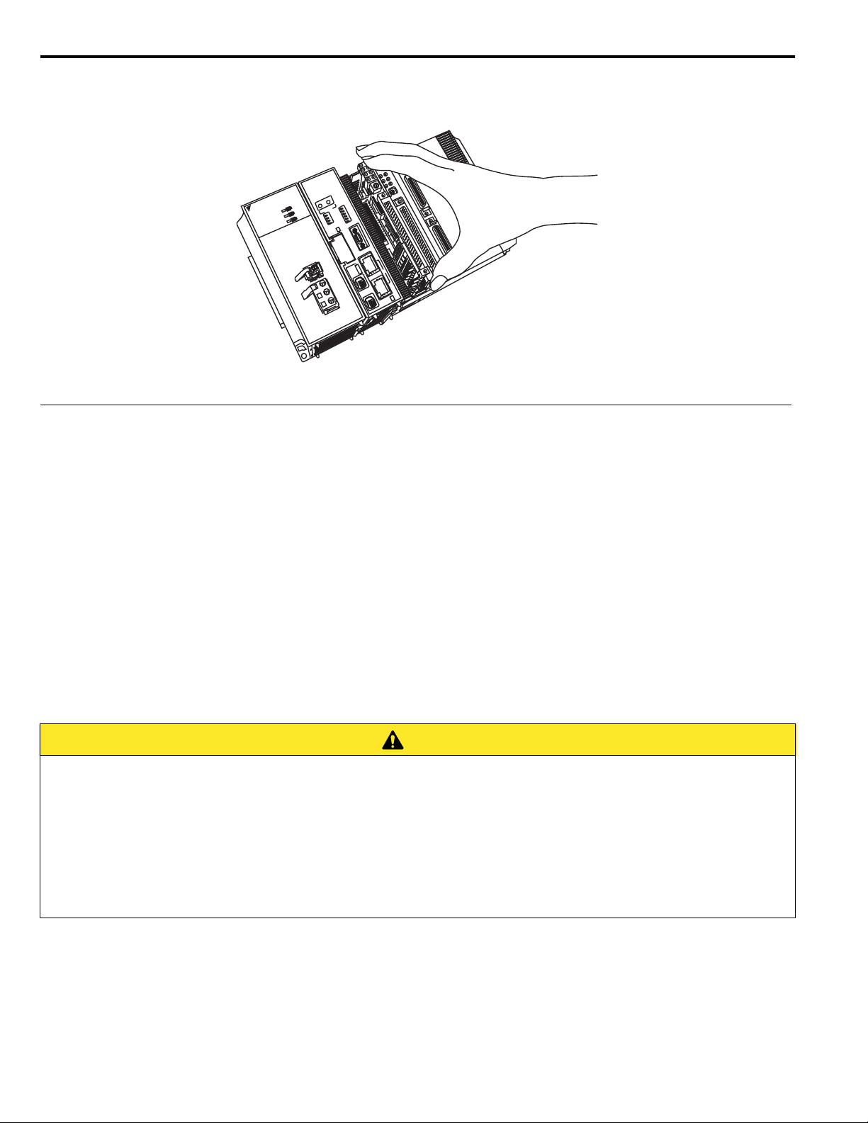
6. Hold the Optional Module at the top and bottom and pull it straight out. Hold the edges of the Module and avoid
touching the components on the Module.
&
&;
470
#./
2
'44
$#6
5#
#5-#9#
19'4
/#./
27
9
612
2#&&4
9
'+0+6
+0+6
2/
%0()
'2/
.1#&
6'56
&456
/06
5$
#%6+8'
612
5#8'
.;176
Note: Put the Module that you removed into the bag that was supplied when you purchased it and store the Module in this bag.
Installing and Replacing the Battery in the CPU
Battery Installation
&
1
10
VJGTPGV
7$
.-
+++
.-
0
0
.+0-#%6
/
This Battery provides backup power for the SRAM data when the power supply to the MP3200iec Series CPU Unit is
turned OFF. The Battery provides backup power for the following data.
• Alarm history
• Calendar
• Retain Variables
Note: One Battery is provided with the CPU Unit. The Battery is not connected when the Unit is delivered.
Battery Replacement
When the total power OFF time exceeds 1 year, the voltage of the Battery will drop, and the BAT indicator on the CPU
Unit will light.
Replace the Battery within 2 weeks of when the BAT indicator first lights.
Battery Replacement Procedure
• Allow only qualified personnel trained in safety procedures to replace the Battery. Incorrect Battery
replacement may result in electric shock. Als o, ma chin e mal function may occur, possibly r esul t ing in i njur y or
machine damage.
• Replace the Battery only while power is supplied to the Basic Unit. Replacing the Battery while the power
supply to the Basic Unit is turned OFF may result in loss of the data stored in memory in the Unit.
• Do not touch the electrodes of the Battery. Static electricity may damage the electrodes.
• The Basic Module con tains a lithium battery. When you replace the Battery, separate the used Battery from
normal waste and dispose of it according to all local ordinances.
1. Back up the programs and data stored in the Basic Unit.
Note: The backup can be used to recover the data if the data accide ntally gets deleted during Battery replacement.
2. Confirm that the RDY indicato r on the CPU Unit is lit.
24 YASKAWA America, Inc. MP3200iec Hardware Manual YAI-SIA-IEC-5
Page 27
9 Installation
LiTHIUM
Black lead
Red lead
3. Open the battery holder on the bottom of the CPU Unit.
4. Disconnect the lead connector of the Battery from the connector on the CPU Unit, and remove the Battery from the
battery holder.
5. Insert the Replacement Battery into the battery holder, and securely connect the lead connector of the Battery to the
connector of the CPU Unit.
Connector on CPU Unit
Battery lead connector
Battery
YASKAWA America, Inc. MP3200iec Hardware Manual YAI-SIA-IEC-5 25
Battery holder
Page 28
9 Installation
Press in.
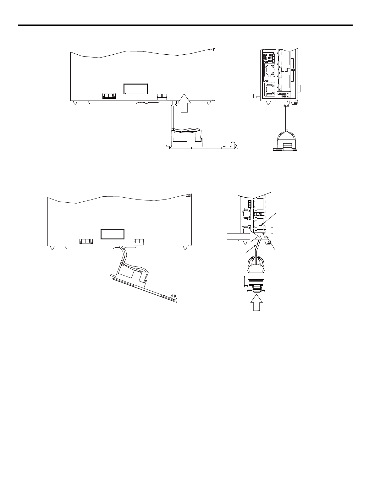
6. Press the connector back into the CPU Unit.
7. Hold the connector, and while pressing it toward the CPU Unit’s internal circuit board (the board on the side of the
clamp), move the Battery and the battery holder into the CPU Unit.
Note: If this procedure is not follow ed, th e battery le ads may b e pinched b etween the Batte ry and the circuit boa rd, caus ing stress o n the
leads. If that occurs, the battery ho ld er will bulge after step 8 of the procedure.
Hold the connector
and press in.
2 battery leads
8. Close the battery holder and confirm that the BAT indicator on the CPU Unit is not lit.
This completes Battery replacement.
Clamp
CPU Unit internal circuit board
(on the side of the clamp)
Move the Battery.
26 YASKAWA America, Inc. MP3200iec Hardware Manual YAI-SIA-IEC-5
Page 29
10 DIP Switch Settings
SW
2
TEST
NO
MNT
E-PM0
E-PM1
10 DIP Switch Setti ng s
The DIP switch settings are only referenced wh en the po wer is in itially t urned ON with t he exceptio n of the ST OP switc h,
which will immediately STOP IEC Application program execution.
SW1
STOP
E_INIT
INIT
CNFG
LOAD
D-RST
Switch Name Setting Operating Mode Default Details
S1-6 STOP
S1-5 E_INIT
S1-4 INIT
S1-3 CNFG
S1-2 LOAD
S1-1 D-RST
ON User program stopped
OFF User program running
ON Use default IP Address
OFF
ON
OFF
ON Self-configuration Mode
OFF Normal Operation
ON USB Mode
OFF Internal FLASH Mode
ON System Use
OFF Normal Operation
Use IP Address set in the
Configuration
For diagnostic
purposes only
For diagnostic
purposes only
SW
1
NO
OFF Stops the user program execution.
OFF
OFF
OFF
OFF
OFF Not used.
When ON, overrides E thernet configuration according to
Table A.
The controller uses the fixed, default configuration.
For diagnostics only. Turning this switch ON may help
restore communications to the controller if the configuration
is corrupted or invalid.
The controller creates Axes and I/O for all connected
devices. (Auto-c on figu r ation)
When ON, load either the user project or firmware from t he
USB thumb drive. See Table B for details.
SW2
Sets the Ethernet port condition and other operating conditions.
The switch setting is read only when the module is first turned ON.
Switch Switch Name State Operation Mode Default Description
When E-INIT is ON and E-PM0 is ON,
overrides Ethernet configuration according to
T able A.
When E-INIT is ON and E-PM1 is ON,
overrides Ethernet configuration according to
T able A.
When ON, the IP address is scrolled across the
seven segment display.
When ON, controller starts up in supervisor
mode. In this mode MECHATROLINK III,
PLC, Modbus/T CP and Ethernet/IP do not
start. The controller firmware ca n be updated,
and clearing DOS FS alarms will repair the
DOS FS.
S2-4 E-PM0
S2-3 E-PM1
S2-2 TEST
S2-1 MNT
ON
OFF
ON
OFF
ON Display IP Address
OFF Normal Operation
ON Maintenance Mode
OFF Normal Operation
Use Default IP Address according to
Table A
Use Default IP Address according to
Table A
OFF
OFF
OFF
OFF
YASKAWA America, Inc. MP3200iec Hardware Manual YAI-SIA-IEC-5 27
Page 30

10 DIP Switch Settings
Note: If the E-INIT switch is in the “ON” position when the controller is pow ered up , the IP addre ss of th e co ntroll er will be 19 2.16 8.1.1.
If the switch is in the “OFF” position at power on, then the IP address defined in the system configuration setup will be in effect.
E-INIT, E-PM0, E-PM1 and both Rotary Switches can override the Ethernet configuration. When E-INIT, E-PM0 and
E-PM1 are ON, ON, OFF, respectively, the upper nibble and lower nibbles of the last byte are given by the rotary
switches X16
Static Configuration OFF N/A N/A
192.168.1.1 ON OFF OFF
192.168.1.RotarySwitches ON ON OFF
DHCP ON OFF ON
1
and X160, respect i vely.
T able A Ethernet Overrides
E-INIT E-PM0 E-PM1
On startup, the controller will automatically load firmware or user projects based on the LOAD and MNT switches. The
USB thumb drive is not available in any other circumstances.
Table B Firmware and User Project Loading
LOAD MNT
Load user project from USB thumb driv e. ON OFF
Install firmware and user project from USB thumb drive. ON ON
28 YASKAWA America, Inc. MP3200iec Hardware Manual YAI-SIA-IEC-5
Page 31

11 LED Indicators
RDY
RUN
ALM
BAT
M-ALM
ERR
11 LED Indicators
The following table shows the indicators that show the operating status of the controller and error information.
Indicator Color Status
RDY Green Lit during normal operation.
RUN Green Lit during execution of user program.
ALM Red Lit/blinking when warning occurs.
ERR Red
BAT Red Lit during battery alarm.
M-ALM Red Lit when a MECHATROLINK Communications Error occurs.
Seven Segment Display
The following situations use the seven segment display:
• Manufacturing: During programming the seven segment display outputs "FLASH...". When finished, the seven
segment display outputs "donE".
• Startup: If the controller cannot boot because of a bad firmware image check sum, the seven segment display outputs
"bOOt ERROR".
• IP Address: If the TEST switch is ON, then the seven segment display outputs the IP address.
• Firmware update: During programming the seven segment display outputs "FLASH...". When finished, the seven
segment display outputs "donE".
ON at initial power-up while firmware is loading. Turns off if
firmware is valid. Lit/blinking when malfunction occurs.
YASKAWA America, Inc. MP3200iec Hardware Manual YAI-SIA-IEC-5 29
Page 32

12 Self-Configuration
STOP
SUP
INIT
CNFG
MON
TEST
1. Turn OFF the power supply
Turn OFF the 24 VDC power supply of the MP3200Siec.
2. Set DIP Switches
Turn ON CNFG in the DIP switch (SW1) of the MP3200Siec.
ࠉࠉࠉ
3. Turn ON the power supply
Turn ON the 24 VDC power supply of the MP3200Siec.
4. Check the LED Indicators
Check that LED display of the MP3200Siec basic module is
changed as follows:
5. DIP switch resetting
Turn the CNFG DIP switch (SW1) of the MP3200Siec to OFF.
ࠉࠉࠉ
STOP
SUP
INIT
CNFG
MON
TEST
RDY
RUN
ALM
ERR
BAT
M-ALM
RDY
RUN
ALM
ERR
BAT
M-ALM
: Lit : Unlit
12 Self-Configuration
DIP Switch
Self-Configuration after Adding Devices such as Servopacks
By performing the following operation, a definition for devices detected on the MECHATROLINK-III network is
created. Before performing the operation, turn ON the power supply for each network node.
MotionWorks IEC
The MotionWorks IEC (Express or Pro) configuration can detect the configuration and provide the user with
configuration choices . If a S tart Up Configu rati on was alre ady saved on the cont rolle r, the self-configure functi on will not
allow new devices to be discovered. In this case, add them offline manually first.
30 YASKAWA America, Inc. MP3200iec Hardware Manual YAI-SIA-IEC-5
Page 33

13 MECHATROLINK-III Specifications
13 MECHATROLINK-III Specifications
The specifications of the MECHA TROLINK-III Network Master that is built into the CPU Unit are given in the following
table.
Item Specification Remarks
Communications ASIC JL-100 Number of Communications Lines 1 -
MECHATROLINK
communications
settings
Number of Communications Ports
(Connectors)
Communications Method M-III Baud Rate 100 Mbps -
Communications Cycle
Number of Connected
Master
Stations
Message Relaying Not Supported. C2 Messages Not Supported. Retries Supported. 0 to 4 retries
Asynchronous Setting of
High-speed Scan Cycle
and Communications
Cycle
2-
250 μs/0.5 ms/
1 ms/1.5 ms/2 ms/2.5 ms/3 ms/
3.5 ms/4 ms
62 stations -
Not supported. An alarm will occur if setting is attempted.
-
CPU Unit Specifications
Item Specification
Calendar Battery backup accurate to 1 minute of error per month.
Ethernet
M-III 1981386-1 ×2 (TycoAMP)
USB
RS-232C
/422
Protection Hardware watchdog timer (PLD): 0 to 510 ms (register setting)
Relay Output
Backup Circuit Battery: BR-1/2AA (Panasoni c), 3.0 V
Connector DUSB-ARA42-T11A-FA (DDK), type A connector
Function USB 2.0 host, 3 sp eeds (HS/FS/LS), 1 port
Connector HDR-EC14LFDTN-SLE+ (HONDA)
Function
10BASE-T, 100BASE-TX
Auto-Negotiation / Baseline Wander Correction / Auto-MDIX
SOUT, SIN, RTS, CTS, and DTR
9,600 to 115K bps, UART built into CPU Unit is used.
Contacts normally open for RUN status (RDY indicator lit), and OFF for WDT error status. The relay
is built into the Power Supply Unit.
YASKAWA America, Inc. MP3200iec Hardware Manual YAI-SIA-IEC-5 31
Page 34

14 MECHATROLINK-III Network Topologies
CPU Unit
No terminating resistor is required.
Up to 32 stations, including Servos and I/O
14 MECHATROLINK-III Network To pologies
You can connect the MP3200iec Series Controller and drives or I/O with cascaded connections, star connections, or
mixed cascaded/star network topologies. The following figures show examples of these types of network topologies.
Cascaded Connection
Cascaded connections allow you to connect one or more series of slave stations from the CPU Unit MECHATROLINKIII ports. Regardless of whether a single MECHATROLINK-III port is used, as shown in , or two CPU Unit
MECHATROLINK-III ports are used, as shown in Figure 1, these are called cascaded connections.
Figure 1
Figure 1 Cascaded Connections Using Only One Port
Figure 2
CPU Unit
No terminating
resistor is
required.
Up to 32 Servo stations
Up to 62 stations, including I/O
Figure 2 Cascaded Connections Using Two Ports
Note: 1. Do not connect more than 32 stations up to the final slave station to any one CPU Unit port.
2. The maximum number of stations that you can connect with cascaded connections depends on the communications cycle. Refer to
Communications Cycle and the Number of Slave Stations on page 35.
No terminating
resistor is required.
32 YASKAWA America, Inc. MP3200iec Hardware Manual YAI-SIA-IEC-5
Page 35

14 MECHATROLINK-III Network Topologies
Hub Module
Hub Module
Star Connections
Star connections allow you to connect slave stations through Hub Modul es. Each port on a Hub Module connects to only
one slave station. You can also connect one additional Hub Module to the first Hub Module.
CPU Unit
Note: 1. Terminating resistors are not required.
2. The maximum number of stations that you can connect with star connections depends on the communications cycle. Refer to
Communications Cycle and the Number of Slave Stations on page 35.
YASKAWA America, Inc. MP3200iec Hardware Manual YAI-SIA-IEC-5 33
Page 36

14 MECHATROLINK-III Network Topologies
CPU Unit
No terminating
resistor is required.
No terminating
resistor is required.
Hub Module
Mixed Cascaded/Star Connections
You can combine both cascaded and star network topologies.
Note: 1. Do not connect more than 32 st ations to a single CPU Unit port, incl uding the Hub Modules.
2. The maximum number of stations that you can connect with a mixed cascaded/star connections depends on the communications cycle.
Refer to Communications Cycle and the Number of Slave Stations on page 35.
34 YASKAWA America, Inc. MP3200iec Hardware Manual YAI-SIA-IEC-5
Page 37

15 MECHATROLINK-III Synchronization between Modules
15 MECHATROLINK-III Synchronization between Modules
Communications Cycle and the Number of Slave Stations
The relationship between the MECHATROLINK communications cycle and the number of slave stations is given in the
following tables.
Cascaded Connections
Communications
Cycle
125 μs1 to 3 –
250 μs1 to 7 –
500 μs1 to 12 –
1 ms 1 to 21 –
1.5 ms 1 to 27 –
2 ms 1 to 32 –
3 ms 1 to 38
4 ms 1 to 62
Star Connections
Communications Cycle Number of Connected Stations
Number of Connected
Stations
If more than 32 stations are connected, two ports must be used.
No more than 32 stat ions can be connected to a single port .
If no more than 32 stations are connected, two ports must be used.
No more than 32 stat ions can be connected to a single port .
125 μs1 to 4
250 μs1 to 8
500 μs1 to 14
1 ms 1 to 32
1.5 ms 1 to 62
2 ms 1 to 62
3 ms 1 to 62
4 ms 1 to 62
Connection Conditions
Mixed Cascaded/Star Connections
Communications Cycle
125 μs 1 to 4 Only star connections can be used.
250 μs 1 to 8 A single cascaded connection series must consist o f no more than 2 stations.
500 μs 1 to 14 A single cascaded connection series must consist of no more than 6 stations.
1 ms 1 to 29 A single cascaded connection series must consist of no more than 7 stations.
1.5 ms 1 to 42 A single cascaded connection series must consist of no more than 8 stations.
2 ms 1 to 42 A single cascaded connection series must consist of no more than 16 stations.
3 ms 1 to 42 A single cascaded connection series must consist of no more than 18 stations.
4 ms 1 to 62 A single cascaded connection series must consist of no more than 21 stations.
Note: The above connection conditions assume that the following conditions are met: Number of transmission bytes: 48, Distance
between stations: 100 m., Number of retries: 1.
NOTICE: If the SigmaWin+ is connected through a Machine Controller, the SigmaWin+ may not be usable if there are too many
SERVOPACK stations connected. If this occurs, either connect the SigmaWin+ to the SERVOPACK (CN7) directly, or increase the
communicat ions cycle.
YASKAWA America, Inc. MP3200iec Hardware Manual YAI-SIA-IEC-5 35
Number of
Connected Stations
Connection Conditions
Page 38

15 MECHATROLINK-III Synchronization between Modules
NOTICE
NOTICE
Timing at Which Modules Are Synchronized
Modules are automatically synchronized when the power supply is cycled.
If you perform any of the following operations after turning ON the power supply, save the settings to flash memory and
then cycle the power supply again.
• When operation changes from asynchronized to synchronized as a result of changing the communications cycle
• When operation changes from synchronized to asynchronized or from asynchronized to synchronized as a result of
changing the high-speed scan setting
• When the minimum response time in the MPiec controller is changed.
Changing Synchronization Cycles
When the scan cycle is changed, MECHATROLINK communications with all slave stati ons conne ct ed to the SVC32 ar e
reset. Operation automatically changes to synchronized when communications are restored.
MECHATROLINK communications continue for all other Modules.
1. When you change the MECHATROLINK cycle, do so either with the CPU Function Module stopped or when motion commands are not being
executed. Otherwise, application operations may be affected.
2. When changing the MECHATROLINK setting, the following operation will occur because MECHATROLINK communications are reset.
• Position information and zero point return comp letion information for Servo axes will be lost.
Changing the MECHATROLINK Communications Cycle
Operation is automatically synchronized as long as the high-speed scan setting is an integral multiple of the
communic ations cycle.
It is not necessary to cycle the power supply.
If asynchronous operation is set as a result of changing the communications cycle, an alarm will occur for the Servo
axis and an I/O error will occur for the I/O station. If this happens, change the setting back to synchronized, save the
settings to flash memory, and then cycle the power supply.
36 YASKAWA America, Inc. MP3200iec Hardware Manual YAI-SIA-IEC-5
Page 39

16 Devices Connectable via MECHATROLINK-III
16 Devices Connectable via MECHATROLINK-III
Servopacks
The following table shows Servopacks that are compatible with MECHATROLINK-III and can be connected to the
controller.
Model Details
SGDV-21 Σ-V Series AC Servo amplifiers for rotary motors
SGDV-E21 Σ-V Series Mini AC Servo amplifiers for rotary motors
SGDV-H21A Σ-V Series 200 VAC Large Capacity AC Servo amplifiers for rotary motors
SGDV-J21A Σ-V Series 400 VAC Large Capacity AC Servo amplifiers for rotary motors
SGDV-25 Σ-V Series AC Servo amplifiers for linear motors
I/O Modules
The following table shows the module that is compatible with MECHATROLINK-III and can be connected to the
controller.
Model Details
JEPMC-MTD2310-E
64-point I/O Module
24VDC, 64 inputs, 64 outputs
YASKAWA America, Inc. MP3200iec Hardware Manual YAI-SIA-IEC-5 37
Page 40

17 Connecting the RLY OUT Connector
RLY OUT
24 VDC
0 VDC
POWER
Ground to 100 Ω max.
24-VDC
power supply
Power
supply
Error: OFF
Normal operation: ON
RLY OUT output
17 Connectin g th e RLY OUT Connector
The RLY OUT connector connects the status output terminal. It is a normally open contact relay output. The RLY OUT
connector is linked to the operation of the RDY indicator: The contacts close when the indicator lights, and they open
when the indicator goes out.
Note: When the RDY indicator is lit, the Controller is operating normally. It does not necessarily mean that the user programs are being
executed.
RLY OUT Connector Specifications
The operation of the RLY OUT connector is linked to the operation of the RDY indicator on the CPU Unit.
RDY indicator lit: Circuit closed
RDY indicator not lit: Circuit open
Contact Ratings
Input
Voltage
24 VDC
125 VAC
RLY OUT Connector Connection Cable
Current Capacity
0.5 A (resistive load)
0.25 A (inductive load)
0.4 A (resistive load)
0.2 A (inductive load)
To connect the RLY OUT connector, use a cable with a wire size of AWG28 to AWG14 (0.08 to 2.0 mm2) and a
maximum outer diameter of 3.4 mm.
The procedure to make the RLY OUT connector cable is the same as for the 24-VDC power supply cable.
Note: You can use the RLY connector on the Power Supply Unit only on the Rack to which the CPU Unit is mounted. On Racks without
the CPU Unit, the power supply circuit is always open.
RLY OUT Connector Connection Example
Refer to the following figure for an example of connecting the RLY OUT connector.
38 YASKAWA America, Inc. MP3200iec Hardware Manual YAI-SIA-IEC-5
Page 41

18 Ethernet Connector Details
'VJGTPGV
.+0-
/
Connects to other devices by Ethernet (100Base-TX/10Base-T).
Ethernet Connector Specification and Pin Array/Indicator Light
The following table provides the Ethernet connector specifications.
18 Ethernet Connector Details
Connector
Name
Ethernet 8 RJ-45 CAT5 Socket RJ-45 CAT5 Plug Pulse Engineering
Number of
Pins
Module Side Cable Side Manufacturer
Connector Model
The following table provides Ethernet connector pin array / indicator light details.
Pin Number Signal Name Description
1 TXD+ Transmitted data + side
2 TXD- Transmitted data – side
3 RXD+ Received data + side
4––
5––
6 RXD- Received data – side
7––
8––
Display Name Display Color Description
LINK Yellow
100M Green
Ethernet Cable
Lit: Connect
Unlit: Unconnected
Lit: Connected at 100Mbps, or automatically negotiating
Unlit: Connected at 10Mbps
For the Ethernet cable, use a twisted pair cable with RJ-45 connector. Yaskawa strongly recommends the use of shielded
ethernet cables.
Ethernet
Type
10Base-T Category 3 or more
100Base-T Category 5 or more
Category Remarks
• When connecting to remote equipment through a hub: Straight cable
• When connecting to remote equipment without using a hub: Cross cable
YASKAWA America, Inc. MP3200iec Hardware Manual YAI-SIA-IEC-5 39
Page 42

18 Ethernet Connector Details
Hub
or Switch
MP3200iec
Hub
or Switch
10Base-T
(Straight cable)
Station
StationStation
Up to 100mUp to 100m
Up to 100m
Up to 100m
Up to 100m
Station
Up to 100m
When connecting to a HUB without using the
auto-negotiation function, set the HUB side to
half-duplex mode.
10 Base-T (crossover cable, up to 100m)
MP3200iec
Ethernet Connection Examples
The following are examples of Ethernet network connections via 10Base-Tx cable:
Connection Example 1 (When using a hub or switch)
Specification
Item When Connecting to a Repeater HUB When Connecting to a Switching HUB
Cable Length between Node-HUB 100m or less 100 m or less
Cable Length between HUBs 100m or less 100 m or less
Number of HUBs between Nodes Up to four Unlimited
Connection Example 2
40 YASKAWA America, Inc. MP3200iec Hardware Manual YAI-SIA-IEC-5
Page 43

18 Ethernet Connector Details
CAUTION
Hub
or Switch
MotionWorks IEC
MP3200iec
YASKAWA SERVOPACK
200V
SGDS-01A12A
SW1
CHARGE
C
N
3
A/B
C
N
1
C
N
2
C
N
4
L1
L2
L2C
L1C
B1/
B2
U
V
W
C
N
6
SERVOPACK
Core
Core
Core
100Base-T
(straight cable)
Servomotor
Other station
The following are examples of Ethernet network connections via 100Base-Tx cable:
High frequency wave noise from other devices in the installation environment may cause errors in
communications using Ethe rnet or MECHATROLINK-III connections. Wh en designi ng a syst em, use pr otectiv e
measures to avoid the influence of high frequency wave noise as follows:
1. Wiring
2. Communication system (Ethernet)
Wire Ethernet or MECHATROLINK-III cables so that they are well-separated from other cable systems such as the main circuit or
power lines.
• Communicate data to a remote device through TCP/IP communication.
• If necessary, increase the number of communication retries.
• Yaskaw a strongly recommends shielded Ethernet cables.
3. Attach a ferrite core.
Ethernet: Attach it to the communication port side and the external equipm ent side of the MP3200iec unit.
YASKAWA America, Inc. MP3200iec Hardware Manual YAI-SIA-IEC-5 41
Note: Recommended ferrite core.
Model Manufacturer
E04SR301334 Seiwa Electric Mfg. Co., Ltd
Page 44

19 Option Module - AI-01 (Analog Input) Module
AI-01
LED indicator
Analog input
connector CN1
RUN
CN1
CN2
Analog input
connector CN2
125 mm
95 mm
19.3 mm
19 Option Module - AI-01 (Analog Input) Module
Appearance
Module Functions
The AI-01 module is an analog input module with voltage and/or current input modes.
Module Specifications
The following table shows the AI-01 Module hardware specifications.
Item Specifications
Classification I/O Module
Name AI-01
Model JAPMC-AN2300
Analog Input
Accuracy
Analog Input Range -10 to +10V 0 to +10V 0 to 20 mA
Number of Channels 8 ((4/ connector)×2)
Number of Channels to be Used Any number from 1 to 8
Isolation
Max. Rated Input ±15V ±30 mA
Input Impedance 20 kΩ 250 kΩ
Resolution 16-bit (-31276 to +31276) 15-bit (0 to +31276)
Absolute Accuracy 100 mV Max 0.3 mA Max
Input Conversion Time 1.4 msec Max
Connectors
LED Indicator RUN (green)
25°C ±0.1% (±10 mV) ±0.1% (± 0.02 mA)
0 to 55°C ±0.3% (±30 mV) ±0.3% (±0.06 m A )
Between input connector and system power supply: Photocoupler isolation
Between channels: Not isolated.
CN1: Input connector
CN2: Input connector
42 YASKAWA America, Inc. MP3200iec Hardware Manual YAI-SIA-IEC-5
Page 45

L 150 mm
26-core
Loose wires
NP JEPMC-W6080-05
Marking tube (Label)
LED Indicator
19 Option Module - AI-01 (Analog Input) Module
Item Specifications
Current Consumption 500 mA Max
Dimensions 125×95 (H×D)
Mass 100 g
Indicator
RUN Green Normal operation Operation stopped (no access from CPU)
Connector Specifications
Connector Name # of Pins
CN1/CN2 26 10226-52A3PL
Indicator
Color
Status when Lit Status when not Lit
Module Side Cable Side Manufacturer
Applicable Cable: JEPMC-W6080-oo
Standard Cable Model and External Appearance
Model Length External Appearance (JEPMC-W6080-oo)
JEPMC-W6080- 05 0.5 m
Connector Model
• Connector
10126-3000VE
•Shell
10326-52A0-008
(Screw locking), or
10326-52F0-008
(One-touch lock ing)
Sumitomo 3M Corporation
JEPMC-W6080- 10 1.0 m
JEPMC-W6080- 30 3.0 m
YASKAWA America, Inc. MP3200iec Hardware Manual YAI-SIA-IEC-5 43
Page 46

19 Option Module - AI-01 (Analog Input) Module
25
26
13
12
15
1
2
14
1
V1
14
MDP1
2
G1
15
G1
3 A1 16 MDN1
4 V2 17 MDP2
5G2 18G2
6 A2 19 MDN2
7 V3 20 MDP3
8G3 21G3
9 A3 22 MDN3
10 V4 23 MDP4
11 G4 24 G4
12 A4 25 MDN4
13 26
25
26
13
12
15
1
2
14
1
V5
14
MDP5
2
G5
15
G5
3 A5 16 MDN5
4 V6 17 MDP6
5G6 18G6
6 A6 19 MDN6
7 V7 20 MDP7
8G7 21G7
9 A7 22 MDN7
10 V8 23 MDP8
11 G8 24 G8
12 A8 25 MDN8
13 26
Connector Pin Arrangement
The AI-01 Module Connector (CN1/CN2) pin arrangement is shown below.
CN1 Connector Pin Arrangement
Pin Arrangement Viewed from Wiring Side
CN2 Connector Pin Arrangement
Pin Arrangement Viewed from Wiring Side
Standard Cable Wiring Table
The wiring table for the standard cable JEPMC-W6080- is shown below.
Pin Wire Color
1
2
3
14
16
4
5
44 YASKAWA America, Inc. MP3200iec Hardware Manual YAI-SIA-IEC-5
Gray Red – – – V1/V5 V1/V5 Voltage input 1/5
Gray Black – – – G1V/G5V
Orange Red – – – G1A/G5A
Orange Black – – – A1/A5 A1/A5 Current input 1/5
Yellow Red – DP1/DP5 MDP1/MDP5 Mode switching terminal 1/5
Yellow Black – DN1/DN5 MDN1/MDN5 Mode switching terminal 1/5
Pink Red – – V2/V6 V2/V6 Voltage input 2/6
Pink Black – – G2V/G6V
Yellow Black – – G2A/G6A
Marking
Color Marking
Label on Marking
Tube
Signal Name Function
G1/G5 Ground 1/5
G2/G6 Ground 2/6
Page 47

19 Option Module - AI-01 (Analog Input) Module
DANGER
Pin Wire Color
6 Yellow Black – – A2/A6 A2/A6 Current input 2/6
17 White Red – DP2/DP6 MDP2/MDP6 Mode switching terminal 2/6
19 White Black – DN2/DN6 MDN2/MDN6 Mode switching terminal 2/6
7 White Red – – V3/V7 V3/V7 Voltage input 3/7
8
9
20 Gray Red – DP3/DP7 MDP3/MDP7 Mode switching termi nal 3/7
22 White Black – DN3/DN7 MDN3/MDN7 Mode switching terminal 3/7
10
11
12
23
25 Orange Black – – DN4/DN8 MDN4/MDN8 Mode switching terminal 4/8
White Black – – G3V/G7V
Gray Red – – G3A/G7A
Gray Black – – A3/A7 A3/A7 Current input 3/7
Orange Red – – V4/V8 V4/V8 Voltage input 4/8
Orange Black – – GV4/GV8
Pink Red – – G4A/G8A
Pink Black – – A4/A8 A4/A8 Current input 4/8
Orange Red – – DP4/DP8 MDP4/MDP8 Mode switching terminal 4/8
Marking
Color Marking
Label on Marking
Tube
Signal Name Function
G3/G7 Ground 3/7
G4/G8 Ground 4/8
Columns “Label on M arkin g T u be”, “Si gnal Name”, and “Fu nction ” dis play t he val ues f or conn ector s CN1 and CN2 in
the format “CN1 /CN2”, respectively.
YASKAWA America, Inc. MP3200iec Hardware Manual YAI-SIA-IEC-5 45
Page 48

19 Option Module - AI-01 (Analog Input) Module
DC/DC
Converter
+5V
0V
+15V
-15V
0V
D/A
Converter
Internal circuit
+5V
Photocoupler
Voltage input
Current input
Mode
10
12
25
23
-
+
GND
CH8
11
Multiplexer
Ground
Voltage input
Current input
Mode
4
6
19
17
-
+
GND
CH2
5
Voltage input
Current input
Mode
Ground
1
3
16
14
2
-
+
GND
CH1
Ground
Shell
R R
R
RR
R
RR
R
10k
10k
256.5
10k
10k
256.5
10k
10k
256.5
Circuit Configuration
46 YASKAWA America, Inc. MP3200iec Hardware Manual YAI-SIA-IEC-5
Page 49

DANGER
DC/DC
Converter
+5V
0V
+15V
-15V
0V
D/A
Converter
Internal circuit
+5V
Photocoupler
Voltage input
Current input
Mode
10
12
25
23
-
+
GND
CH8
11
Multiplexer
Ground
Voltage input
Current input
Mode
4
6
19
17
-
+
GND
CH2
5
Voltage input
Current input
Mode
Ground
1
3
16
14
2
-
+
GND
CH1
Ground
Shell
R R
R
RR
R
RR
R
10k
10k
256.5
10k
10k
256.5
10k
10k
256.5
CN1 Connector Connection Example
19 Option Module - AI-01 (Analog Input) Module
• Use the standard cable (J EPMC-W6080- ) for AI-01 Modules to connect to ex te rnal de vices . Use a relay termina l
block to connect the AI-01 module to external devices because the wiring distance varies between the AI-01 module
and each external device.
• Ground the cable shield between an external device and the relay terminal block on the external device side.
YASKAWA America, Inc. MP3200iec Hardware Manual YAI-SIA-IEC-5 47
Page 50

20 Option Module - AO-01 (Analog Output) Module
A
O
-01
LED indicator
Analog output
connector CN1
RUN
CN1
125 mm
95 mm
19.3 mm
20 Option Module - AO-01 (Analog Output) Module
Appearance
Module Functions
The AO-01 module has four channels for anal og output. Two types of analog outpu t ranges a re availabl e; -10 t o +10V and
0 to +10V.
Module Specifications
The following table shows the AO-01 Module hardware specifications.
Item Specifications
Name AO-01
Model JAPMC-AN2310-E
Number of Channels 4
Isolation
Analog Output Rang e ±10V 0 to +10V
Resolution 16-bit (-31276 to +31276) 15-bit (0 to +31276)
Absolute Accuracy 100 mV Max 0.3 mA Max
Analog Output
Accuracy
Input Conver sion Time 1.2 msec Max
Connectors CN1: Output connector
LED Indicator RUN (green)
Current Consum ption 500 mA Max
Dimensions 125 × 95 (H×D)
Mass 90 g
Indicators
25°C ±0.1% (±10 mV)
0 to 55°C ±0.3% (±30 mV)
Between channels: Not isolated.
Between output connector and system power supply: Photocoupler isolation
Indicator
RUN Green Normal operation Operation stopped (no access from CPU)
48 YASKAWA America, Inc. MP3200iec Hardware Manual YAI-SIA-IEC-5
Indicator
Color
Status when Lit Status when not Lit
Page 51

Connector Specifications
20 Option Module - AO-01 (Analog Output) Module
Name
Analog Output
Connector
Connector
Name
CN1 20 10220-52A3PL
# of Pins
Module Side Cable Side Manufacturer
Applicable Cable: JEPMC-W6090-oo
Standard Cable Model and External Appearance
Model Length External Appearance (JEPMC-W6090-oo)
JEPMC-W6090-05 0.5 m
JEPMC-W6090-10 1.0 m
JEPMC-W6090-30 3.0 m
CN1 Pin Layout Diagram
Connector Model
• Connector 10126-30 00VE
• Shell 10326-52A0-008
(Screw locking), or
10326-52F0-008
(One-touch locking)
Sumitomo 3M
Corporation
Standard Cable Wiring Table
The following shows the pin arrangement for standard cable JEPMC-W6090.
Pin Wire Color
1 Orange Red Analog Output 0
2 Gray Red Analog Output 1
3
4
5
6 White Red Pulse input ground
7
8 White Black (-)
9
10~20 Twisted-pair cable
YASKAWA America, Inc. MP3200iec Hardware Manual YAI-SIA-IEC-5 49
Orange Black Ground 0
Gray Black A_Pulse+
Yellow Red (-)
Yellow Black C-Phase latch input common (5V)
Marking
Color
Function
Page 52

20 Option Module - AO-01 (Analog Output) Module
DANGER
AO-01 Module Connector Connection Example
CN1 Connector Connection Example
• Use the AO-01 standard cable (JEPMC-W6090-) for the connection to the external device. Use the junction
terminal block because the distance between the external devices and the module are different as seen on the above
diagram.
• Ground the cable shield between the external devices and the junction terminal block by the external device side.
50 YASKAWA America, Inc. MP3200iec Hardware Manual YAI-SIA-IEC-5
Page 53

21 Option Module - DO-01 (Digital Output) Module
DANGER
0
24
DO_24V
Output
register
DO_OUT
DO_COM
+24V
R
Photocoupler
R
Transistor
21 Option Module - DO-01 (Digital Output) Module
Appearance/Indicators
Module Functions
The DO–01 module is equipped with 64 digital outputs.
Output Circuit Specifications
The following table shows the DO-01 Module output circuit specifications.
Item Specifications
Outputs 64 points
Output Format Transistor/open collector, sink mode outpu t
Isolation Method Photocoupler
Output Voltage + 24VDC (+19.2 to +28.8V)
Output Current 100 mA Max
Leakage Current When OFF 0.1 mA Max
ON Time/OFF Time
Number of Commons 8 points
Protection Circuit Fuse connected to each common line
Fuse Rating 1A
Error Detection Fuse blowout detection
ON: 0.5 ms Max
OFF: 1 ms Max
DO-01 Digital Output Circuit (Sink Mode Output) Connection Example
A fuse is inserted into the output commo n line of th e DO-01 Module for circuit protection. However , the fuse may not
be blown out in the cases such as layer shorts in outputs. To ensure the circuit protection, provide a protective element
such as fuse in each output as shown in the above diagram.
DO-01 Module Connections
Connects the DO-01 Module to external output signals.
YASKAWA America, Inc. MP3200iec Hardware Manual YAI-SIA-IEC-5 51
Page 54

21 Option Module - DO-01 (Digital Output) Module
50-core
Loose wires
1
3
5
7
9
11
13
15
17
19
21
23
25
+24V_1
DO_02
DO_06
+24V_2
DO_10
DO_14
+24V_3
DO_18
DO_22
+24V_4
DO_26
DO_30
N.C.
26
28
30
32
34
36
38
40
42
44
46
48
50
OV_1
DO_03
DO_07
OV_2
DO_11
DO_15
OV_3
DO_19
DO_23
OV_4
DO_27
DO_31
N.C.
27
29
31
33
35
37
39
41
43
45
47
49
DO_01
DO_15
OV_1
DO_09
DO_13
OV_2
DO_17
DO_21
OV_3
DO_25
DO_29
OV_4
50
49
25
24
26
27
1
2
Pin Arrangement Viewed from Wiring Side
2
4
6
8
10
12
14
16
18
20
22
24
DO_00
DO_04
OV_1
DO_08
DO_12
OV_2
DO_16
DO_20
OV_3
DO_24
DO_28
OV_4
External outputs: 64 points
Name
External I/O
Connector
Connector
Name
CN1/CN2 50 10250-52A2JL
No of
Pins
Module Side Cable Side Manufacturer
Applicable Cable: JEPMC-W6060-oo
Standard Cable Model and External Appearance
Name Model Length External Appearance (JEPMC-W6060-oo)
JEPMC-W6060-05 0.5 m
Cables for DO-01
Modules
JEPMC-W6060-10 1.0 m
JEPMC-W6060-30 3.0 m
Connector Model
• Connector
• 10150-3000VE
•Shell
• 10350-52A0-008
• (Screw locking), or
• 10350-52F0-008
• (One-touch locking)
Sumitomo 3M
Corporation
Connector Pin Arrangement
The DO-01 Module Connector (CN1 and CN2) pin arrangement is shown below.
CN1 Connector Pin Arrangement
52 YASKAWA America, Inc. MP3200iec Hardware Manual YAI-SIA-IEC-5
Page 55

CN2 Connector Pin Arrangement
Pin Arrangement Viewed from Wiring Side
1
26
27
2
49
24
50
25
Standard Cable Wiring Table
21 Option Module - DO-01 (Digital Output) Module
1
DO_32
2
DO_36
4
OV_5
6
DO_40
8
DO_44
10
OV_6
12
DO_48
14
DO_52
16
OV_7
18
DO_56
20
DO_60
22
OV_8
24
+24V_5
3
DO_34
5
DO_38
7
+24V_6
9
DO_42
11
DO_46
13
+24V_7
15
DO_50
17
DO_54
19
+24V_8
21
DO_58
23
DO_62
25
N.C.
DO_33
27
DO_37
29
OV_5
31
DO_41
33
DO_45
35
OV_6
37
DO_49
39
DO_53
41
OV_7
43
DO_57
45
DO_61
47
OV_8
49
OV_5
26
DO_35
28
DO_39
30
OV_6
32
DO_43
34
DO_47
36
OV_7
38
DO_51
40
DO_55
42
OV_8
44
DO_59
46
DO_63
48
N.C.
50
The wiring table for the standard cable JEPMC-W6060- is shown below
Pin Wire Color Marking Signal Name Function
1 Orange — +24V_1/5 24V power supply 1/5
2 Gray — DO_00/32 Digital output 0/32
3 White — DO_02/34 Digital output 2/34
4
Yellow — DO_04/36 Digital output 4/36
5 Pink — DO_06/38 Digital output 6/38
6
Orange — — 0V_1/5 Common ground 1/5
7
Gray — — +24V_2/6 24V power supply 2/6
8 White — — DO_08/40 Digital output 8/40
9
Yellow — — DO_10/42 Digital output 10/42
10 Pink — — DO_12/44 Digital output 12/44
11
Orange — — — DO_14/46 Digital output 14/46
12
13 White — — — +24V_3/7 2 4V power supply 3/7
14
15 Pink — — — DO_18/50 Digital output 18/50
16 Orange — — — — DO_20/52 Digital output 20/52
17
18 White — — — — 0V_3/7 Common ground 3/7
19
20
21 Orange — — — — Continuous DO_26/68 Digital output 26/60
22 Gray — — — — Continuous DO_28/60 Digital output 28/62
23 White — — — — Continuous DO_30/62 Digital output 30/64
24
25 Pink — — — — Continuous N.C
26
27 Gray — DO_01/33 Digital output 1/33
28 White — DO_03/35 Digital output 3/35
Gray — — — 0V_2/6 Common ground 2/6
Yellow — — — DO_16/48 Digital output 16/48
Gray — — — — DO_22/54 Digital output 22/54
Yellow — — — — + 24V_4/8 24V power supply 4/8
Pink — — — — DO_24/58 Digital output 24/58
Yellow — — — — Continuous 0V_4/8 Common ground 4/8
Orange — 0V_1/5 Common ground 1/5
YASKAWA America, Inc. MP3200iec Hardware Manual YAI-SIA-IEC-5 53
Page 56

21 Option Module - DO-01 (Digital Output) Module
DANGER
Pin Wire Color Marking Signal Name Function
29 Yellow — DO_05/37 Digital output 5/37
30
Pink — DO_07/39 Digital output 7/39
31 Orange — — 0V_1/5 Common ground 1/5
32 Gray — — 0V_ 2/6 Common ground 2/6
33 White — — DO_09/41 Digital output 9/41
34
Yellow — — DO_11/43 Digital output 1 1 /43
35 Pink — — DO_13/45 Digital output 13/45
36
Orange — — — DO_15/47 Digital output 15/47
37 Gray — — — 0V_2/6 Common ground 2/6
38 White — — — 0V_3/7 Common ground 3/7
39
Yellow — — — DO_17/49 Digital output 17/49
40 Pink — — — DO_19/51 Digital output 19/51
41
Orange — — — Continuous DO_21/53 Digital output 21/53
42
Gray — — — Continuous DO_23/55 Digital output 23/55
43 White — — — Continuous 0V_3/7 Common ground 3/7
44
Yellow — — — Continuous 0V_4/8 Common ground 4/8
45
Pink — — — Continuous DO_25/57 Digital output 25/57
46
Orange — — — — DO_27/59 Digital output 27/59
47 Gray ———————— DO_29/61 Digital output 29/61
48 White ———————— DO_31/63 Digital output 31/63
49
Yellow ———————— 0V_4/8 Common ground 4/8
50
Pink ———————— N.C
Columns “Signal Name” and “Function” display the values for connectors CN1 and CN2 in the format “CN1/CN2”
respectively.
54 YASKAWA America, Inc. MP3200iec Hardware Manual YAI-SIA-IEC-5
Page 57

22 Option Module - LIO-01/02 Module
LIO-01
LED indicators
Switch
I/O connector
22 Option Module - LIO-01/02 Module
Appearance
External Appearance
The following figure shows the external appearance of the LIO-01/02 Modules
The LIO-01 Module provides digital I/O and encoder input functions. There are 16 digital inputs (DI) and 16 digital
outputs (DO) for the digital I/O function. There is also one encoder input.
The following diagra m giv es an outli ne of the LI O-01 Mo dule f uncti ons. The only f unctiona l d iff erenc e betwe en the LIO01 and the LIO-02 is the active state of the output circuits
Refer to LIO-01 Digital Output Circuit (Sink Mode Output) Connection Example on page 58 and Refer to LIO-02
Digital Output Circuit (Source Mode Output) Connection Example on page 58.
The LIO-02 Module status display LED indicators (LD1 to LD8) change based on the SW1 rotary switch settings. The
following table shows the ON/OFF indicator display for digital input and digital output.
Outline of Functions
LED Indicators and Switch Settings
YASKAWA America, Inc. MP3200iec Hardware Manual YAI-SIA-IEC-5 55
Page 58

22 Option Module - LIO-01/02 Module
LD3
LD2
LD1
LD4
LD7
LD6
LD5
LD8
SW1
0
5
1
2
3
4
6
7
8
9
Indicators
Indicator Color SW1 Status when Lit
Board Status Indicators
LD1 Normal operation: Lit, Error: Not lit
LD2 DI-00 to DI-07 status. Lit when any digital input is turned ON.
LD3 DO-00 to DO-07 status. Lit when any digital output is turned ON.
0
LD1 to LD8 G re en
1 Digital input indicators: When DI00 to DI07 turn ON, corresponding indicators (LD1 to LD8) are lit.
2 Digital input indicators: When DI08 to DI15 turn ON, corresponding indicators (LD1 to LD8) are lit.
3 Digital output indicators: When DO00 to DO07 turn ON, corresponding indicators (LD1 to LD8) are lit.
4 Digital output indicators: When DO08 to DO15 turn ON, corresponding indicators (LD1 to LD8) are lit.
5
LD4 Pulse A/B input. Lit when phase A/B is turned ON.
LD5 Normal operation: Lit, Error: Not lit
LD6 DI-08 to DI-15 status. Lit when any digital input is turned ON.
LD7 DO-08 to DO-15 status. Lit when any digital output is turned ON.
LD8 Pulse Z input. Lit when phase Z is turned ON.
PI input Indicators
LD1
LD2
LD3
LD4
Pulse A input
Pulse B input
Pulse Z input
-
LD5
LD6
LD7
LD8
High speed output set
Phase-Z latch
Digital input latch
-
Specifications
Module Specifications
Item Specifications
Name LIO-01/02
Model JAPMC-IO2300/JAPMC-IO2301
16 inputs
Digital Inputs
24VDC, 4.1 mA, combined sink mode/source mode i nputs
(DI_01 also used for position registation latch.)
Digital Outputs
16 outputs
24VDC transistor open-collector outputs, sink mode (-01)/Source mode (-02) outputs.
Phase A/B/Z inputs
Phase-A/B: 5V differential input, not isolated, Max frequency: 4 M H z
Encoder Input
Phase-Z: 5V/12V photocoupler input, Max frequency: 500 kHz
Latch input
Position registration latch on phase-C or DI _0 1.
Switches Rotary switch (SW1)
Dimensions (mm) 125 x 95 (H x D)
Mass 80 g
56 YASKAWA America, Inc. MP3200iec Hardware Manual YAI-SIA-IEC-5
Page 59

22 Option Module - LIO-01/02 Module
5.6k Ω/0.5 W
Vcc
DI_COM
+24 V
DI_IN
Input register
0
24
R
R
R
R
5.6 k
Ω/ 0.5 W
Vcc
680 Ω
DI_COM
+24 V
DI_IN
22 kΩ
1 k
Ω
2200PF
0.01 μF
Input register
0
24
R
R
R
R
Input Circuit Specifications
Item Specifications
Inputs 16 points
Input Format Sink mode/Sourc e mode input
Isolation Method Photocoupler
Input Voltage ±24VDC, ±20mv
Input Current 4.1 mA (typ.)
ON Voltage/Current 15V min./2.0 mA min.
OFF Voltage/Current 5V Max/1.0 mA Max
ON Time/OFF Time
Number of Commons 8 points (DI_COM0: DI_00 to DI_07, DI_COM1: DI_08 to DI_15)
Other Functions
Digital Input Circuit (Sink Mode Input) Connection Example
ON: 0.5 ms Max
OFF: 0.5 ms Max
DI_01 is shared with position registration latch. If DI_01 is turned ON while position registration latch
inputs are enabled, the encoder position will be latched.
Digital Input Circuit (Source Mode Input) Connection Example
Output Circuit
The following table shows the LIO-01/02 Module output circuit specifications.
Item Specifications
Outputs 16 p oints
Output Format
Isolation Method Photocoupler
Output Voltage +24VDC, ±20mv
Output Current 100 mA Max
Leakage Current When OFF 0.1 mA Max
ON Time/OFF Time
YASKAWA America, Inc. MP3200iec Hardware Manual YAI-SIA-IEC-5 57
LIO-01 Transistor, open collector sink mode outputs
LIO-02 Transistor, open collector source mode outputs
ON: 1 ms Max
OFF: 1 ms Max
Page 60

22 Option Module - LIO-01/02 Module
R
R
R
0
24
DO_24V
Output
register
DO_OUT
DO_COM
+24 V
0
24
+24V
DO_24V
Output
register
DO_OUT
DO_COM
R
R
R
Item Specifications
Number of Commons 16 points
Protection Circuit
Error Detection Blown fuse detection
Other Functions DO_01 is shared with encoder position detection
LIO-01 Digital Output Circuit (Sink Mode Output) Connection Example
The fuses are not for circuit protection. Th ey are for fire protection at output shorts. Attach a fu se
externally to each output if circuit protection is required.
LIO-02 Digital Output Circuit (Source Mode Output) Connection Example
Pulse Input Circuit
The following table shows the LIO-01/02 Module encoder circuit specifications.
Item Specifications
Number of Encoders 1 (Phase-A /B/Z input)
Encoder Circuit
Input Mode Phase-A/B, signed, incrementa l/decremental
Latch Input
Phase-AB: 5V differential input, not isolated, Max frequency: 4 MHz
Phase-Z: 5V/12V photocoupler input, Max frequency: 500 kHz
Position registration latch on phase-Z or DI_01.
Response time: 5 ms Max for phase-Z input; 60 ms Max for DI_01 input.
58 YASKAWA America, Inc. MP3200iec Hardware Manual YAI-SIA-IEC-5
Page 61

22 Option Module - LIO-01/02 Module
+5 V
0 V
Phase-A
A1
220Ω
Pulse Generator
Phase-B
PA
PAL
PB
PBL
GND
B1
A2
B2
B3
B4
A4
A3
+5 V
Latch input or
phase-Z pulse
PC
PCL5
PCL12
R
R
R
220Ω
R
B1A1
B24A24
Encoder Circuit Connection Example
LIO–01/02 Standard Cable Wiring Table
Connector Pin Arrangement
The following table shows the connector pin arrangement for LIO-01/02 Modules viewed from the wiring side.
Pin Wire Color
A1
Orange Red — PA I Phase-A pulse (+)
Wire Marking
Color Marking
Signal
Name
I/O Function
A2 Gray Red — PB I Phase-B pulse (+)
A3 White Red — PC I Phase-C pulse (+)
A4
Yellow Red — GND I Pulse input ground
A5 Pink Red — DO_COM P Output common
A6
Orange Red — — DO_24V P +24VDC input
A7 Gray Red — — DO_15 O Output 15
A8 White Red — — D O_13 O Output 13
A9
Yellow Red — — DO_11 O Output 11
A10 Pink Re d — — DO_09 O Output 9
A11
A12
Orange Red — — — DO_07 O Output 7
Gray Red — — — DO_05 O Output 5
A13 White Red — — — D O_03 O Output 3
A14
A15
A16
Yellow Red — — — DO_01 O Output 1
Pink Red — — — DI_15 I Input 15
Orange Red — — — — DI_13 I Input 13
A17 Gray Red — — — — DI_11 I Input 11
A18 White Re d — — — — DI_09 I Input 9
A19
Yellow Red — — — — DI_07 I Input 7
A20 Pink R e d — — — — DI_05 I Input 5
A21
Orange Red — — — — Continuous DI_03 I Input 3
A22 Gray R e d — — — — Continuous DI_01 I Input 1
A23 White Re d — — — — Continuous DI_COM0 P Input common 0
A24 Shield FG - Frame ground
B1
B2 Gray Black — PBL I Phase-B pulse (–)
Orange Black — PAL I Phase-A pulse (–)
B3 White Black — PCL5 I
B4
YASKAWA America, Inc. MP3200iec Hardware Manual YAI-SIA-IEC-5 59
Yellow Black — PCL12 I
Phase-C pulse
(-5V input)
Phase-C pu lse
(-12V input)
Page 62

22 Option Module - LIO-01/02 Module
Pin Wire Color
B5 Pink Black — DO_CO M P Output common
B6 Orange Black — — DO_24V P +24V inp ut
B7 Gray Black — — DO_14 O Output 14
B8 White Black — — DO_12 O Output 12
B9
B10 Pink Black — — DO_08 O Output 8
B11
B12 Gray Black — — — DO_04 O Output 4
B13 White Black — — — DO_02 O Output 2
B14
B15 Pink Black — — — DI_14 I Input 14
B16
B17
B18 White Black — — — — DI_08 I Input 8
B19
B20
B21
B22 Gray Black — — — — Continuous DI_00 I Input 0
B23 White Black — — — — Continuous DI_COM1 P Input common 1
B24 Shield FG - Frame ground
Yellow Black — — DO_10 O Output 10
Orange Black — — — DO_06 O Output 6
Yellow Black — — — DO_00 O Output 0
Orange Black — — — — DI_12 I Input 12
Gray Black — — — — DI_1 0 I Input 10
Yellow Black — — — — DI_06 I Input 6
Pink Black — — — — DI_04 I Input 4
Orange Black — — — — Continuous DI_02 I Input 2
Color Marking
Wire Marking
Signal
Name
I/O Function
• P: Power supply input; I: Input signal; O: Open-collector output
Connector Specifications
Connects the external I/O signals and encoder input signals.
External output: 16 points, Encoder input: 1 channel
Name
I/O Connector I/O 48 FCN-36 5P048-AU
Cables
Name Model Number Length (JEPMC-W2061-oo)
Cable for LIO01/02 Modules
Connector
Name
JEPMC-W2061-A5 0.5 m
JEPMC-W2061-01 1.0 m
JEPMC-W2061-03 3.0 m
# of Pins
Module Cable Manufacturer
Connector Model
FCN-360C048-E (cover),
FCN-361J048-AU (jack)
Fujitsu
component
60 YASKAWA America, Inc. MP3200iec Hardware Manual YAI-SIA-IEC-5
Page 63

DANGER
Phase-A
Pulse Generator
Fuse
Pulse input
Latch input
or phase-Z
pulse
Latch input or phase-Z pulse
Digital input
Digital input
Digital output
External input signals
External input signals
External output signals
Phase-B
24 VDC
24 VDC
Fuse blown
detection circuit
Fuse
220Ω
220Ω
+5V
0V
+5V
5V
A2
B2
A4
PB
PBL
GND
PC
PCL5
PCL12
A3
A24
B24
B3
B4
PA
PAL
A1
B1
DI_COM0
DI_01
DI_02
DI_03
DI_04
DI_05
DI_06
DI_07
DI_00
A23
B22
A22
B21
A21
B20
A20
B19
A19
R
R
DI_COM1
DI_09
DI_10
DI_11
DI_12
DI_13
DI_14
DI_15
DI_08
B23
B18
A18
B17
A17
B16
A16
B15
A15
R
R
R
R
R
R
R
L
L
L
L
L
L
L
L
L
L
L
L
L
L
L
L
DO_00
DO_01
DO_02
DO_03
DO_04
DO_05
DO_06
DO_24V
DO_07
DO_08
DO_09
DO_10
DO_11
DO_12
DO_13
DO_14
DO_15
DO_COM
DO_COM
B6
A6
B14
A14
B13
A13
B12
A12
B11
A11
B10
A10
B9
A9
B8
A8
B7
A7
A5
B5
R
LIO-01 Module Connections
22 Option Module - LIO-01/02 Module
• Connect a fuse suit able for the load specifica t ions in the output signal circuit in series with the load. If an external
fuse is not connected, load shorts or overloads could result in fire, destruction of the load device, or damage to the
output element.
• The pins A5 and B5, and the pins A6 and B6 are internally connected. Connect them externally as well.
YASKAWA America, Inc. MP3200iec Hardware Manual YAI-SIA-IEC-5 61
Page 64

22 Option Module - LIO-01/02 Module
+5V
0V
Phase-A
Pulse generator
+5V
Pulse input
Latch input
or phase-Z
pulse
Latch input or
phase-Z pulse
Phase-B
5V
A2
B2
A4
PB
PBL
GND
PC
PCL5
PCL12
A3
A24
B24
B3
B4
PA
PAL
A1
B1
External input
signals
DI_COM0
DI_01
DI_02
DI_03
DI_04
DI_05
DI_06
DI_07
DI_00
A23
B22
A22
B21
A21
B20
A20
B19
A19
24 VDC
Digital input
R
R
External input
signals
DI_COM1
DI_09
DI_10
DI_11
DI_12
DI_13
DI_14
DI_15
DI_08
B23
B18
A18
B17
A17
B16
A16
B15
A15
24 VDC
Digital input
R
R
R
R
R
R
R
L
L
L
L
L
L
L
Digital output
External output
signals
L
L
L
L
L
L
L
L
L
Fuse open
detection circuit
Fuse
24 VDC
Fuse
DO_24V
DO_24V
DO_00
DO_01
DO_02
DO_03
DO_04
DO_05
DO_06
DO_07
DO_08
DO_09
DO_10
DO_11
DO_12
DO_13
DO_14
DO_15
DO_COM
DO_COM
B6
A6
B14
A14
B13
A13
B12
A12
B11
A11
B10
A10
B9
A9
B8
A8
B7
A7
A5
B5
R
L
Load
External Fuse
LIO-02 Module Connections
62 YASKAWA America, Inc. MP3200iec Hardware Manual YAI-SIA-IEC-5
Page 65

23 Option Module - LIO-04/05 Modules
DANGER
LED indicators
I/O connector
(CN1)
LIO-04
RUN
FU
CN2
CN1
I/O connector
(CN2)
FURUN
23 Option Module - LIO-04/05 Modules
External Appearance
The following figure shows the external appearance of the LIO-04/05 Modules.
The LIO-04/05 Modules are Optional Boards for the MP2300Siec which provide a digital I/O function. There are 32
digital inputs (DI) and 32 digital outputs (DO) (sink mode outputs) for the digital I/O function.
The following table shows the status of LIO-04/05 Module LED indicators.
The burnout detection circuit will not function when there is no external 24V power supply.
Outline of Functions
Indicators
Indicator Name Indicator Color Status
RUN Green
FU Red
Lit: Module normal
Not lit: Module error
Lit: One of the output protection fuses is blown.
Not lit: All of the output protection fuses are normal.
YASKAWA America, Inc. MP3200iec Hardware Manual YAI-SIA-IEC-5 63
Page 66

23 Option Module - LIO-04/05 Modules
LD3
LD2
LD1
LD4
LD7
LD6
LD5
LD8
SW1
0
5
1
2
3
4
6
7
8
9
Indicators
Switch Settings
The LIO-04/05 Module status display the LED indicators (LD1 to LD8) change based on the SW1 rotary switch setting.
The following table shows the ON/OFF indicator display for digital input and digital output.
Indicator Color SW1 Status when Lit
Board Status Indicators
LD1 Normal operation: Lit, Error: Not lit
LD2 DI_00 to DI_07 status. Lit when any digital input is turned ON.
LD3 DO_00 to DO_07 status. Lit when any digital output is turned ON.
LD4 Pulse A/B input. Lit when phase A/B is turned ON.
0
LD5 Normal operation: Lit, Error: Not lit
LD6 DI_08 to DI_15 status. Lit when any digital input is turned ON.
LD7 DO_08 to DO_15 status. Lit when any digital output is turned ON.
LD1 to LD8 Green
LD8 Pulse Z input. Lit when phase Z is turned ON.
1 Digital input indicators: When DI_00 to DI_07 turn ON, corresponding indicators LD1 to LD8 are lit.
2 Digital input indicators: When DI_08 to DI_15 turn ON, corresponding indicators LD1 to LD8 are lit.
3 Digital output indicators: When DO _ 00 to DO _07 turn ON, corresponding indicators LD1 to LD8 are lit.
4 Digital output indicators: When DO _ 08 to DO _15 turn ON, corresponding indicators LD1 to LD8 are lit.
PI Input Indicators
LD1
5
LD2
LD3
LD4
Pulse A input
Pulse B input
Pulse Z input
-
LD5
LD6
LD7
LD8
Coincidence detection
Phase-Z latch
Digital input latch
-
Module Specifications
The following table shows the hardware specifications of the LIO-04/05 Module.
Item Specifications
Name LIO-04/LIO-05
Model JAPMC-IO2303/JAPMC-IO2304
32 inputs
24VDC, 4.1 mA, combined sink mode/source mode inputs
(DI_00, 01, 16, and 17 also used for interrupts.)
Digital Inputs
Digital Outputs
Indicators
Dimensions (mm) 125 x 95 (H x D)
Mass 80 g
64 YASKAWA America, Inc. MP3200iec Hardware Manual YAI-SIA-IEC-5
Simultaneously ON Inputs
16 points (8 inputs/common): At ambient temperatur e of 55°C and 24VDC
10 points (5 inputs/common): At ambient temperat ure of 55°C and 28.8VDC
Refer to the following characteristics graph for details.
32 outputs
24VDC transistor open- c ollector outputs, sink mode outputs
RUN (green)
ERR (red)
Page 67

23 Option Module - LIO-04/05 Modules
5.6kΩ/0.5W
Vcc
DICOM
+24V
DI_IN
Input register
0
24
Photocoupler
R
R
R
R
5.6kΩ/0.5W
Vcc
DICOM
+24V
DI_IN
Input register
0
24
R
R
R
R
Photocoupler
Input Circuit Specifications
The following table shows the LIO-04/05 Modules input circuit specifications.
Item Specifications
Inputs 32 points
Input Format Sink mode, source mode input
Isolation Method Photocoupler (PS2805-4)
Input V oltage ±24VDC (+19.2 to +28.8V)
Input Current 4.1 mA (typ.)
ON Voltage/Current 15VDC min./2.0 mA min.
OFF Voltage/Current 5VDC min./1.0 mA min.
ON Time/OFF Time
Number of Commons 8 points
Digital Input Circuit (Sink Mode Input) Connection Example
ON: 0.5 ms Max
OFF: 0.5 ms Max
Digital Input Circuit (Source Mode Input) Connection Example
Output Circuit
The following table shows the LIO-04/05 Module’s output circuit specifications.
Item Specifications
Outputs 32 points
Output Format
Isolation Method Photocoupler
Output Voltage +24VDC (+19.2 to +28.8VDC)
Output Current 100 mA Max
Leakage Current When OFF 0.1 mA Max
LIO-04 Transistor, sink mode output
LIO-05 Transistor, source mode output
YASKAWA America, Inc. MP3200iec Hardware Manual YAI-SIA-IEC-5 65
Page 68

23 Option Module - LIO-04/05 Modules
0
24
+24V
Output
register
DO_OUT
0V
+24V
R
Photocoupler
R
Transistor
Item Specifications
ON Time/ OFF Time
Number of Commons 1 per 8 outputs
Protection Circuit
Fuse Rating 1A
Error Detection Fuse blowout detection
LIO-04 Digital Output Circuit (Sink Mode Output) Connection Example
ON: 0.5 ms Max
OFF: 1 ms Max
The fuses are not for circuit protection. They are for fire protection at output sho rts. Attach a fuse
externally to each output if circuit prote ctio n is requ ired.
LIO-05 Digital Output Circuit (Source Mode Output) Connection Example
+24V
DO_OUT
0V
Output
register
R
R
R
Photocoupler
Transistor
+24V
0
24
66 YASKAWA America, Inc. MP3200iec Hardware Manual YAI-SIA-IEC-5
Page 69

23 Option Module - LIO-04/05 Modules
1
3
5
7
9
11
13
15
17
19
21
23
25
DICOM_3
DI_18
DI_22
DI_24
DI_28
N.C.
DO_18
+24V_3
DO_22
DO_24
N.C.
DO_28
N.C.
26
28
30
32
34
36
38
40
42
44
46
48
50
N.C.
DI_19
DI_23
DI_25
DI_29
N.C.
DO_19
N.C.
DO_23
DO_25
OV_4
DO_29
OV_4
27
29
31
33
35
37
39
41
43
45
47
49
DI_17
DI_21
N.C.
DI_27
DI_31
DO_17
OV_3
DO_21
N.C.
DO_27
N.C.
DO_31
50
49
25
24
26
27
1
2
Pin Arrangement Viewed from Wiring Side
2
4
6
8
10
12
14
16
18
20
22
24
DI_16
DI_20
DICOM_4
DI_26
DI_30
DO_16
N.C.
DO_20
N.C.
DO_26
+24V_4
DO_30
LIO-04 Module Connector Pin Arrangement
The LIO-04 Module Connector (CN1 and CN2) pin arrangements are shown below.
CN1 Connector Pin Arrangement
Pin Arrangement Viewed from Wiring Side
1
26
27
2
49
24
50
25
10
12
14
16
18
20
22
24
2
4
6
8
DI_00
DI_04
DICOM_2
DI_10
DI_14
DO_00
N.C.
DO_04
N.C.
DO_10
+24V_2
DO_14
1
3
5
7
9
11
13
15
17
19
21
23
25
DICOM_1
DI_02
DI_06
DI_08
DI_12
N.C.
DO_02
+24V_1
DO_06
DO_08
N.C.
DO_12
N.C.
DI_01
27
29
DI_05
N.C.
31
33
DI_11
35
DI_15
DO_01
37
39
OV_1
DO_05
41
43
N.C.
DO_11
45
47
N.C.
DO_15
49
26
N.C.
DI_03
28
30
DI_07
DI_09
32
34
DI_13
N.C.
36
38
DO_03
N.C.
40
DO_07
42
44
DO_09
OV_2
46
48
DO_13
OV_2
50
CN2 Connector Pin Arrangement
• P: Power supply input, I: Input signal, O: Open collector output
Standard Cable Wiring Table
The wiring table for the standard cable JEPMC-W6060- is shown below.
YASKAWA America, Inc. MP3200iec Hardware Manual YAI-SIA-IEC-5 67
Pin Wire Color Markings Signal Name I/O Function
1
2
3 White — DI_02/18 I/I Digital input 2/18
4
5 Pink — DI_06/22 I/I Digital input 6/22
Orange — DICOM_1/3 P/P Digital Input common 1/3
Gray —DI_00/16I/I
Yellow — DI_04/20 I/I Digital input 4/20
Digital input 0/16
(shared with interrupt input)
Page 70

23 Option Module - LIO-04/05 Modules
DANGER
Pin Wire Color Markings Signal Name I/O Function
6 Orange — — DICOM_2/4 P/P Digital Input common 2/4
7
8 White — — DI_10/26 I/I Digital input 10/26
9 Yellow — — DI_12/28 I/I Digital input 12/28
10
11
12 Gray — — — DO_00/16 O/O Digital output 0/16
13 White — — — DO_02/18 O/O Digital output 2/18
14
15
16
17 Gray — — — — DO_06/22 O Digital output 6/22
18 White — — — — N.C.
19
20
21 Orange — — — — Continuous N.C.
22
23 White — — — — Continuous DO_12/28 O Digital output 12/28
24
25
26 Orange —N.C.
27 Gray — DI_01/17 I/I
28 White — DI_03/19 I/I Digital input 3/19
29
30
31 Orange — — N.C.
32
33 White — — DI_11/27 I/I Digital input 11/27
34
35
36 Orange — — — N.C.
37
38 White — — — DO_03/19 O/O Digital output 3/19
39
40 Pink — — — N.C.
41
42 Gray — — — Continuous DO_07/23 O/O Digital output 7/23
43 White — — — Continuous N.C.
44
45
46
47
48 White ———————— DO_13/29 O/O Digital output 13/19
49
50
Gray — — DI_08/24 I/I Digital input 8/24
Pink — — DI_14/30 I/I Digital input 14/30
Orange — — — N.C.
Yellow — — — N.C.
Pink — — — +24V_1/3 P/P Digit al output 24V supply 1/3
Orange — — — — DO_04/20 O Digital out put 4/20
Yellow — — — — DO_08/24 O/O Digital output 8
Pink — — — — DO_10/26 O/O Digital output 10
Gray — — — — Continuous +24V_2/4 P Digital Output 24V supply 2/4
Yellow — — — — Continuous DO_14/30 O Digital output 14/30
— — — — Continuous N.C.
Digital input 1/17
(shared with interrupt input)
Yellow — DI_05/21 I/I Digital input 5/21
Pink — DI_07/23 I/I Digital input 7/23
Gray — — DI_09/25 I/I Digital input 9/25
Yellow — — DI_13/29 I/I Digital input 13/29
Pink — — DI_15/31 I/I Digital input 15/31
Gray — — — DO_01/17 O/O Digital output 1/17
Yellow — — — 0V_1/3 P/P Digital Output 0VDC common 1/3
Orange — — — Continuous DO_05/21 O/O Digital output 5/21
Yellow — — — Continuous DO_09/25 O/O Digital output 9/25
Pink — — — Continuous DO_11/27 O/O Digital output 11/27
Orange — — — — 0V_2/4 P/P Digital Output 0VDC common 2/4
Gray ———————— N.C.
Yellow ———————— DO_15/31 O/O Digital output 15/31
Pink ———————— N.C.
Columns “Signal Name”, “I/O”, and “Function” display the values for connectors CN1 and CN2 in the format “CN1/
CN2” respectively.
68 YASKAWA America, Inc. MP3200iec Hardware Manual YAI-SIA-IEC-5
Page 71

23 Option Module - LIO-04/05 Modules
1
3
5
7
9
11
13
15
17
19
21
23
25
DICOM_1
DI_02
DI_06
DI_08
DI_12
N.C.
DO_02
+24V_1
DO_06
DO_08
N.C.
DO_12
N.C.
26
28
30
32
34
36
38
40
42
44
46
48
50
N.C.
DI_03
DI_07
DI_09
DI_13
N.C.
DO_03
+24V_1
DO_07
DO_09
OV_2
DO_13
N.C.
27
29
31
33
35
37
39
41
43
45
47
49
DI_01
DI_05
N.C.
DI_11
DI_15
DO_01
OV_1
DO_05
N.C.
DO_11
+24V_2
DO_15
50
49
25
24
26
27
1
2
Pin Arrangement Viewed from Wiring Side
2
4
6
8
10
12
14
16
18
20
22
24
DI_00
DI_04
DICOM_2
DI_10
DI_14
DO_00
N.C.
DO_04
N.C.
DO_10
+24V_2
DO_14
1
3
5
7
9
11
13
15
17
19
21
23
25
DICOM_3
DI_18
DI_22
DI_24
DI_28
N.C.
DO_18
+24V_3
DO_22
DO_24
N.C.
DO_28
N.C.
26
28
30
32
34
36
38
40
42
44
46
48
50
N.C.
DI_19
DI_23
DI_25
DI_29
N.C.
DO_19
+24V_3
DO_23
DO_25
N.C.
DO_29
N.C.
27
29
31
33
35
37
39
41
43
45
47
49
DI_17
DI_21
N.C.
DI_27
DI_31
DO_17
OV_3
DO_21
N.C.
DO_27
+24V_4
DO_31
50
49
25
24
26
27
1
2
Pin Arrangement Viewed from Wiring Side
2
4
6
8
10
12
14
16
18
20
22
24
DI_16
DI_20
DICOM_4
DI_26
DI_30
DO_16
N.C.
DO_20
N.C.
DO_26
+24V_4
DO_30
LIO-05 Module Connector Pin Arrangement
The LIO-05 Module Connector (CN1 and CN2) pin arrangements are shown below.
CN1 Connector Pin Arrangement
• P: Power supply input, I: Input signal, O: Open collector output
CN2 Connector Pin Arrangement
Standard Cable Wiring Table
The wiring table for the standard cable JEPMC-W6060- is shown below.
Pin Wire Color Markings Signal Name I/O Function
1
2 Gray — DI_00/16 I/I Digital input 0/16
3 White — DI_02/18 I/I Digital input 2/18
4
5 Pink — DI_06/22 I/I Digital input 6/22
YASKAWA America, Inc. MP3200iec Hardware Manual YAI-SIA-IEC-5 69
Orange — DICOM_1/3 I/I Digital Input common 1/3
Yellow — DI_04/20 I/I Digital input 4/20
Page 72

23 Option Module - LIO-04/05 Modules
DANGER
Pin Wire Color Markings Signal Name I/O Function
6 Orange — — DICOM_2/4 P/P Digital Input common 2/4
7
Gray — — DI_08/24 I/I Digital input 8/24
8 White — — DI_10/26 I/O Digital input 10/26
9 Yellow — — DI_12/28 I/O Digital input 12/28
10
Pink — — DI_14/30 I/O Digital input 14/30
11
Orange — — — N.C.
12 Gray — — — DO_00/16 O/O Digital output 0/16
13 White — — — DO_02/18 O/O Digital output 2/18
14
Yellow — — — N.C.
15
Pink — — — +24V_1/3 P/P Digital Output 24V supply 1/3
16
Orange — — — — DO_04/20 O Digital output 4/20
17 Gray — — — — DO_06/22 O Digital output 6/22
18 White — — — — N.C.
19
Yellow — — — — DO_08/24 O Digital output 8/24
20
Pink — — — — DO_10/26 O Digital output 10/26
21 Orange — — — — Continuous N.C.
22
Gray — — — — Cont inuous +24V_2/4 P Digital Output 24V supply 2/ 4
23 White — — — — Continuous DO_12/28 O Digital output 1 2/28
24
Yellow — — — — Continuous DO_14/30 O Digital output 14/30
25
Pink — — — — Continuous N.C.
26 Orange —N.C.
27
Gray — DI_01/17 I/I Digital input 1/17
28 White — DI_03/19 I/I Digital input 3/19
29
Yellow — DI_05/21 I/I Digital input 5/21
30
Pink — DI_07/23 I/I Digital input 7/23
31
Orange — — N.C.
32 Gray — — DI_09/25 I/I Digital input 9/25
33 White — — DI_11/27 I/I Digital input 11/27
34
Yellow — — DI_13/29 I/I Digital input 13/29
Pink — — DI_15/31 I/I Digital input 15/31
35
36
Orange — — — N.C.
37
Gray — — — DO_01/17 O/O Digital output 1/17
38 White — — — DO_03/19 O/O Digital output 3/19
39
Yellow — — — 0V_1/3 P/P Digital Output 0VDC common 1/3
40
Pink — — — +24V_1/3 P/P Digital Output 24V supply 1/3
41
Orange — — — Continuous DO_05/21 O/O Digital output 5/21
Gray — — — Continuous DO_07/23 O/O Digital output 7/23
42
43 White — — — Continuous N.C.
44
Yellow — — — Continuous DO_09/25 O/O Digital output 9/25
45 Pink — — — Continuous DO_11/26 O/O Digital output 11/26
46
Orange ———————— 0V_2/4 Digital Output 0VDC common 2/4
47
Gray ———————— +24V_2/4 Digital Output 24V supply 2/4
48 White ———————— DO_13/29 O/O Digital output 13/29
49
Yellow ———————— DO_15/31 O/O Digital output 15/31
50 Pink ———————— N.C.
Columns “Signal Name”, “I/O”, and “Function” display the values for connectors CN1 and CN2 in the format “CN1/
CN2” respectively.
70 YASKAWA America, Inc. MP3200iec Hardware Manual YAI-SIA-IEC-5
Page 73

DANGER
JEPMC-IO2303
+5V
+-
+-
24 VDC
Input 0
Input 1
Input 6
Input 7
+-
+-
24 VDC
6
7
32
10
35
1
2
27
5
30
CN1 connector
pin No.
Common 1
Common 2
Input 8
Input 9
Input 14
Input 15
Internal circuit
5.6 kW
Photocoupler
R
R
Photocoupler
Fuse blowout
detection circuit
38
12
13
41
17
42
16
L
L
L
L
L
24 VDC
+-
43
37
L
Output 0
39
15
Output 1
Output 2
Output 4
Output 5
Output 6
Output 7
Output 3
R
L
L
Photocoupler
45
19
20
48
24
49
23
L
L
L
L
L
24 VDC
+-
50
44
L
Output 8
46
22
Output 9
Output 10
Output 12
Output 13
Output 14
Output 15
Output 11
R
L
L
Fuse blowout
detection circuit
L
Load
External Fuse
(Installed by customer)
LIO-04 Module Connector Connection Examples
CN1 Connector Connection Example
23 Option Module - LIO-04/05 Modules
• Check the polarity of the external power supply when wiring. An adverse connection may cause a load malfunction.
• The pins 39 and 43 and the pins 46 and 50 are internally connected. Connect them externally as well.
YASKAWA America, Inc. MP3200iec Hardware Manual YAI-SIA-IEC-5 71
Page 74

23 Option Module - LIO-04/05 Modules
DANGER
CN2 Connector Connection Example
24 VDC
+-
Common 3
+-
Input 16
Input 17
Input 22
Input 23
24 VDC
+-
Common 4
+-
Input 24
Input 25
Input 30
Input 31
L
Load
External Fuse
(Installed by customer)
CN2 connector
pin No.
1
5.6 kW
2
R
27
5
30
6
Photocoupler
7
32
10
35
JEPMC-IO2303
Photocoupler
R
Photocoupler
+5V
R
Fuse blowout
detection circuit
R
Fuse blowout
detection circuit
Internal circuit
15
12
37
13
38
16
41
17
42
43
39
22
19
44
20
45
23
48
24
49
50
46
Output 16
Output 17
Output 18
Output 19
Output 20
Output 21
Output 22
Output 23
Output 24
Output 25
Output 26
Output 27
Output 28
Output 29
Output 30
Output 31
24 VDC
+-
L
L
L
L
L
L
L
L
24 VDC
+-
L
L
L
L
L
L
L
L
• Check the polarity of the external power supply when wiring. An adverse connection may cause a load malfunction.
• The pins 39 and 32 and the pins 46 and 50 are internally connected. Connect them externally as well.
72 YASKAWA America, Inc. MP3200iec Hardware Manual YAI-SIA-IEC-5
Page 75

DANGER
+
-
-
+
24 VDC
Common 1
Common 2
1
CN1 connector
pin No.
Input 0
Input 1
2
27
Input 6
Input 7
5
30
6
7
32
Input 8
Input 9
10
35
Input 14
Input 15
JEPMC-IO2304
+
-
-
+
DC24V
+5V
5.6 kΩ
Photocoupler
Internal
circuit
R
R
L
L
L
L
L
L
15
12
Output 0
37
Output 1
13
Output 2
38
24 VDC
+
-
41
17
42
16
39
Output 4
Output 5
Output 6
Output 7
Photocoupler
L
Output 3
R
R
L
L
L
L
L
L
L
22
19
Output 8
44
Output 9
20
Output 10
45
24 VDC
+
-
48
24
49
23
46
Output 12
Output 13
Output 14
Output 15
Photocoupler
L
Output 11
R
R
L
Fuse blowout
detection circuit
Fuse blowout
detection circuit
L
Load
External Fuse
(Installed by customer)
LIO-05 Module Connector Connection Examples
CN1 Connector Connection Example
23 Option Module - LIO-04/05 Modules
Check the polarity of the external power supply when wiring. An adverse connection may cause a load malfunction.
YASKAWA America, Inc. MP3200iec Hardware Manual YAI-SIA-IEC-5 73
Page 76

23 Option Module - LIO-04/05 Modules
DANGER
࣭
࣭
࣭
࣭
࣭
࣭
+
-
-
+
24 VDC
Common 3
Common 4
1
CN2 connector
pin No.
Input 16
Input 17
2
27
Input 22
Input 23
5
30
6
7
32
Input 24
Input 25
10
35
Input 30
Input 31
JEPMC-IO2304
+
-
-
+
24 VDC
+5V
5.6 kW
Photocoupler
Internal
circuit
R
R
L
L
L
L
L
L
15
12
Output 16
37
Output 17
13
Output 18
38
24 VDC
+
-
41
17
42
16
39
Output 20
Output 21
Output 22
Output 23
Photocoupler
L
Output 19
R
R
L
L
L
L
L
L
L
22
19
Output 24
44
Output 25
20
Output 26
45
24 VDC
+
-
48
24
49
23
46
Output 28
Output 29
Output 30
Output 31
Photocoupler
L
Output 27
R
R
L
Fuse blowout
detection circuit
Fuse blowout
detection circuit
L
Load
External Fuse
(Installed by customer)
CN2 Connector Connection Example
Check the polarity of the external power supply when wiring. An adverse connection may cause a load malfunction.
74 YASKAWA America, Inc. MP3200iec Hardware Manual YAI-SIA-IEC-5
Page 77

24 Option Module - LIO-06 Module
DANGER
LIO-06
ALMRUN
CN1
Module External Appearance
24 Option Module - LIO-06 Module
Outline of Functions
The LIO-06 Module has digital I/O, analog I/O, and pulse encoder functionality, including a registration latch input. The
LIO-06 Module is fully compatible with the MP940 I/O connector.
When converting equipment from the prior generation MP940 controller, users should bear in mind that the analog
inputs that had previo usly bee n wired to the V-REF and T- REF inputs on the SGDH must now be co nnected directl y to
the LIO-06 option module.
LED Indicators and Switch Settings
Display Name Color Status when Lit Staus when OFF
RUN Green Normal Stopped. (No access by CPU)
ALM Red Fault Normal operation
The ALM light indicates the following conditions
• Fuse fault
•ASIC error
• A-phase disconnect
• B-phase disconnect
YASKAWA America, Inc. MP3200iec Hardware Manual YAI-SIA-IEC-5 75
Page 78

24 Option Module - LIO-06 Module
DANGER
Option Board Specifications
Item Specification
Number of Inputs 8/Common
Input Method Sink/Source
Isolation Photocoupler Isolation
Input Voltage DC24V±20% (DC19.2 to 28.8V)
Digital Input
Digital Output
Analog
Input
Analog
Output
Input Current 4.1mA (TYP)
ON Voltage/Current At least 15V/At least 2mA
OFF Voltage/Current 5V Max/1mA Max
ON/OFF Time ON= 0.5ms Max/OFF= 0.5ms Max
Interrupt 1 (used together with DI_00)
Number of Outputs 8/ Common
Output Method Transistor Sink Output
Isolation Photocoupler Isolation
External Power Sup ply Voltage DC24V±20% (DC19.2 to 28.8V)
Output Current 100mA (Max)
ON Voltage 1V Max
Leak Current at OFF 0.1mA Max
ON/OFF Time ON= 0. 25ms Max/OFF= 1ms Max
Protection Classi fication Unprotected output
Error Detection Blown fuse detection
Number of Channels 1
Isolation Non-isolated
Analog Input Range -10 to +10V
Maximum Rated In pu t ±15V
Input Impedance Approx. 20kΩ
Resolution 16bit (-31276 to +31276)
Absolute Accuracy 100mV Max
Accuracy
Input Filter
Input Conversion Speed 50μs
Number of Channels 1
Isolation Non-isolated
Analog Output Rang e -10 to +10V
Output Impedance 20Ω Max
Resolution 16bit (-31276 to +31276)
Accuracy
Maximum Permissible Load Current ±5mA
Output Delay Time 1.2ms (Time of change from -10+10V)
25ºC ±0.1% (±10mV)
0 to 55ºC ±0.3% (±30mV)
25ºC ±0.1% (±10mV)
0 to 55ºC ±0.3% (±30mV)
Time Constant
Delay Time 1ms(Max) (when -10 to 10V)
0.2×10
–3
The time constant shows th e characte ristic s according to the input f ilter equ ivalent t o the time to reach 0.632 × the in put
voltage.
76 YASKAWA America, Inc. MP3200iec Hardware Manual YAI-SIA-IEC-5
Page 79

24 Option Module - LIO-06 Module
Item Specification
Number of Channels 1
Input Method 5V Differential Max Frequency 4MHz
Isolation Non-isolated
A/B Phase
Counting System
Encoder Input
Number of Input Circuits
Input Method Source Photocoupler I/F Sink/Source Photocoupl er I/F
Isolation Photocoupler Isolation Photocoupler Isolation
Encoder
Input
Current Consumption 5V, 1A Max
Hot Swapping (Modul es) Not Possible
Connector CN1: Digital I/O, Analog I/O, Encoder Input
Indicators RUN (Green), ALM (Red)
Input Voltage
Input Current
Latch Input
ON Voltage
OFF Voltage
Response Time 1μs Max 60μs Max
Minimum ON Pulse Width 1μs60μs
COIN Output
Pulse/Direction
UP/DOWN Counter
2 (C-Phase latch or digital input latch)
The digital input latch is used in conjunction with DI-01 on pin 39.
C-Phase Latch Digital Input Latch
24VDC±20%
12VDC±20%
5VDC±20%
24VDC/12VDC/5VDC are switched by
connector wiring
DC24V: 11mA (TYP)
DC12V: 12mA (TYP)
DC5V: 13mA (TYP)
DC24V: 17V Min
DC12V: 9V Min
DC5V: 3.9V Min
DC24V: 1.6V Max
DC12V: 1.1V Max
DC5V: 0.9V Max
1, digital output
Used together with DO-07 (software switching)
DC24V±20%
4.1mA (TYP)
15V Min
5V Max
Digital Input Circuit
The specifications of the LIO-06 module digital input circuit are shown below.
Item Specification
Number of Inputs 8
Input Method Sink/Source
Isolation Photocoupler Isolation
Input Voltage DC24V±20%
Input Current 4.1mA (TYP )
ON Voltage/Current At least 15V/2.0mA
OFF Voltage/Curr e nt 5V Max/1.0mA Max
ON Time/OFF Time ON=0.5ms Max/OFF=0.5ms Max
Number of Commons 1
Other Functions
YASKAWA America, Inc. MP3200iec Hardware Manual YAI-SIA-IEC-5 77
DI_01 is used together with the position registration latch input, and when enabled, the position
registration latch input latches with the pulse encoder when SI_01 is "ON".
Page 80

24 Option Module - LIO-06 Module
Digital Input Circuit Connection Example
Common
750
5.6
DI
Internal Circuitry
Digital Output Circuit Connection Example
Output
Register
1.2k䃈
R
0.5
Photocoupler
PS280䠍䠉䠐
33k䃈
1000PF
PS2805-4
R
1000PF
Transistor
DTDS14GP
FU
Input Circuitry
Input
Register
Vin
DO
0䠲
Digital Output Circuit
The specifications of the LIO-06 digital output circuit are shown below.
Item Specification
Number of Outputs 8
Output Method Transistor Open Collector Sink Output
Isolation Photocoupler Isolation
External Power Supply Voltage DC24V±20%
Output Current 100mA Max
Leak Current at OFF 0.1mA Max
ON Time/OFF Time ON=0.25ms Max/OFF =1ms Max
Number of Commons 1
Protection Circuit
Fuse Rating 1A
Error Detection Blown fuse detection
78 YASKAWA America, Inc. MP3200iec Hardware Manual YAI-SIA-IEC-5
The fuses are not for circuit protection. They are for fire protection at output sho rts. A fuse
should be attached outside each output when a protective ci rcuit is necessary.
Page 81

24 Option Module - LIO-06 Module
DANGER
Analog Input Circuit
The specifications of the LIO-06 analog input circuit are shown below.
Item Specification
Analog Input Range -10 to +10V
Number of Input Chan ne ls 1
Isolation Non-isolated
Maximum Rated Input ±15V
Input Impeda nce Approx. 20kΩ
Resolution 16-bit (-31276 to +31276)
Accuracy
Input Filter
Conversion Speed 50μs
25ºC ±0.1%(±10mV)
0 to 55ºC ±0.3%(±30mV)
Time Constant
Delay Ti me 1 ms (M a x) ( Whe n -1 0+ 1 0V )
0.2×10
–2
The time constant shows t he charact eristic s accordin g to the input filter eq uivalent to the time to re ach 0.632 × t he input
voltage.
Analog Input Circuit Connection Example
To A/D
Conversion
Ground
Internal Circuitry
Analog Input Characteristics Response Chart
The following shows an analog input response chart and input characteristics diagram for the LIO-06 module.
Input Characteristics Response Chart
Analog Input Value Input Register Value
-10.5V -32768
-10.0V -31276
-5.0V -15638
0.0V 0
+5.0V 15638
+10.0V 31276
+10.5V 32767
• Minimum linearity of +10.0V cannot be assured.
YASKAWA America, Inc. MP3200iec Hardware Manual YAI-SIA-IEC-5 79
Page 82

24 Option Module - LIO-06 Module
Voltage Input Characteristics Diagram
Analog Output Circuit
Analog Input
Value
The specifications of the LIO-06 analog output circuit are shown below.
Item Specification
Output Range -10 to +10V
Number of Output Channels 1
Isolation Non-isolated
Maximum Permissible Load Current ±5mA
Resolution 16-Bit (-31276 to +31276)
Absolute
Output Delay Time 1.2ms (Time of change from -10+10V)
Analog Output Circuit Connection Example
25ºC ±0.1% (±10mV)
0 to 55ºC ±0.3% (±30mV)
80 YASKAWA America, Inc. MP3200iec Hardware Manual YAI-SIA-IEC-5
Page 83

24 Option Module - LIO-06 Module
Analog Output Characteristics Response Chart
The following shows an analog output response chart and output characteristics diagram for the LIO-06 module.
Output Characteristics Response Chart
Analog Output Value Output Register Va lue
-10.5V -32768
-10.0V -31276
-5.0V -15638
0.0V 0
+5.0V 15638
+10.0V 31276
+10.5V 32767
Voltage Output Charac teristics Diagram
Output Register Value
Analog Output
Value
Encoder Circuit
The specifications of the LIO-06 encoder circuit are shown below.
Item Specification
Number of Encode rs 1 channel (A/B/C-Phase Input)
Input Circuits
Input Mode A/B-phase, code, UP/DOWN counter, pulse, and direction
Latch Input
A/B-phase: 5V differential input, non-isolated, max frequency 4MHz
C-Phase: 5V/12V /2 4V ph oto c ou pler input, max frequency 500k H z
Position registration latch with C-Phase of DI_01
Response Time: Max 5μs during C-Phase input, During DI_01 Input: Max 60μs
YASKAWA America, Inc. MP3200iec Hardware Manual YAI-SIA-IEC-5 81
Page 84

24 Option Module - LIO-06 Module
50-core
Loose wires
Encoder Input Circuit Connection Example
Pulse Generator
A-phase
B-phase
LIO-06 Connectors and Pin Layouts
• Connectors
Item Description
Use Connector 10250-52A3PL (Sumitomo 3M) LIO- 06 Connector (RoHS-compatible)
10150-3000VE (Sumitomo 3M) Connector unit
Mating Connector
Standard Cable JEPMC-W2064-oo-E Pigtail
Standard Cable Model and External Appearance
Name Model Length External Appearance (JEPMC-W2064-oo-E)
JEPMC-W2064-A5-E 0.5 m
Cable for LIO-06
Module
(Single loose wire)
Standard Cable Wiring Table
JEPMC-W2064-01-E 1 m
JEPMC-W2064-03-E 3 m
10150-3000PE (Sumitomo 3M) Connector Unit (RoHS-compatible)
10350-52A0-008 ( Sumitomo 3M) Shell screw lock typ e
10350-52F0-00 8 (Sumitomo 3M) One-touch lock type
The following shows the standard cable wiring for the JEPMC-W2064 cable.
Pin Wire Color Markings Signal Name Function
1 Orange — AO Analog Output
2 Gray — AI Analog Input
3White — N.C.
82 YASKAWA America, Inc. MP3200iec Hardware Manual YAI-SIA-IEC-5
Page 85

24 Option Module - LIO-06 Module
Pin Wire Color Markings Signal Name Function
4 Yellow — PA+ A_Pulse+
5 Pink — PA- A_Pulse6 Orange — — GND Pulse Input Ground
7Gray — — N.C.
8White — — N.C.
9 Yellow — — PILC5V C-Phase Latch Input Common (5V)
10 Pink — — PILC24V C-Phase Latch Input Common (24V)
11 Orange — — — N.C.
12 Gray — — — N.C.
13 White — — — DICOM Digital Input Common
14 Yellow — — — DI_00 Digital Input 0
15 Pink — — — DI_02 Digital Input 2
16 Orange — — — — DI_04 Digital Input 4
17 Gray — — — — DI_06 Digital Input 6
18 White — — — — N.C.
19 Yellow — — — — N.C.
20 Pink — — — — DO_24V Digital Output 24V Power Supply
21 Orange — — — — Continuous DO_00 Digital Output 0
22 Gray — — — — Continuous DO_02 Digital Output 2
23 White — — — — Continuous DO_04 Digital Output 4
24 Yellow — — — — Continuous DO_06 Digital Output 6
25 Pink — — — — Continuous DO_GND Digital Output Common Ground
26 Orange — AO_GND Anal og Output Ground
27 Gray — AI_GND Analog Input Ground
28 White — N.C.
29 Yellow — PB+ B_Pulse+
30 Pink — PB- B_Pulse31 Orange — — GND Pulse input ground
32 Gray — — N.C.
33 White — — N.C.
34 Yellow — — PILC12V C-Phase latch input common (12V)
35 Pink — — PIL C-Phase latch input
36 Orange — — — N.C.
37 Gray — — — N.C.
38 White — — — DICOM Digital Input Common
39 Yellow — — — DI_01 Digital Input 1
40 Pink — — — DI_03 Digital Input 3
41 Orange — — — Continuous DI_05 Digital Input 5
42 Gray — — — Continuous DI _07 Digital Input 7
43 Wh ite — — — Continuous N.C.
44 Yellow — — — Continuous N.C.
45 Pink — — — Continuous DO_24V Digital output 24V Power Supply
46 Orange ———————— DO_01 Digital Output 1
47 Gray ———————— DO_03 Digital Output 3
48 White ———————— DO_05 Digital Output 5
49 Yellow ———————— DO_07 Digital Output 7
50 Pink ———————— DO_GND Digital output common ground
Shell Shield Wire
YASKAWA America, Inc. MP3200iec Hardware Manual YAI-SIA-IEC-5 83
Page 86

24 Option Module - LIO-06 Module
DANGER
L
Load
External Fuse
(Installed by customer)
LIO-06 Module Connector Connection Example
An example of LIO-06 module connector connection is shown below.
Relay Terminal Block
+15
V
-15V
Analog Output
Analog Input
Pulse Input
+
+15
V
-15V
+
AO
1
AO_GND
26
AI
2
AI_GND
27
PA+
4
PA-
5
PB+
29
PB-
30
GND
6
GND
31
External Device
L
-10
+10V
FG
External Device
V
-10 +10V
FG
Pulse Generator
+5V
0V
FG
L
L
L
L
L
L
L
L
L
Load
External Fuse
(Installed by customer)
Signal
External Input
Signal
External Output
Z-phase Latch
Input
Digital Input
Digital Output
PILC(24V)
10
PILC(12V)
34
PILC(5V)
9
PIL
35
+5V
Fuse Break
Detection
Circuit
FG Connector
Shell)
13
38
14
39
15
40
16
41
17
42
20
45
21
46
22
47
23
48
24
49
25
50
DICOM
DICOM
DI_00
DI_01
DI_02
DI_03
DI_04
DI_05
DI_06
DI_07
DO_24V
DO_24V
DO_00
DO_01
DO_02
DO_03
DO_04
DO_05
DO_06
DO_07
DO_GND
DO_GND
The cable shield between the external equipment and the junction terminal block should be installed on the external
device side.
84 YASKAWA America, Inc. MP3200iec Hardware Manual YAI-SIA-IEC-5
Page 87

25 Option Module – 218IF-Y1
25 Option Module – 218IF-Y1
Outline of Functions
The 218IF-01 Module has an RS-232C serial interface and an Ethernet interface mounted in it. Pe rs onal computers, HMI
devices, and controllers manufactured by other companies can be connected to the 218IF-01 Module via the serial or
Ethernet connectors.
Hardware
Item Specifications
Name 218IF-Y1
Model JAPMC-CM2301-E
Communication Por ts
Indicators
Switches
Dimensions (mm) 125 × 95 (H × D)
Mass 85 g
RS-232C 1 port (PORT)
Ethernet 1 port (10Base-T)
Module status LED indicators
RUN (green), ERR (red), STRX (green), COL (red), TX (green), RX (green)
INIT
TEST
Functional Specification
Item 218IF-Y1
Interface RS-232 D-sub 9 Ethernet RJ-45
Transmission distance 15 m 100 M/segment (500m in total extension)
Transmission speed Configurable between 9600 and 57600 bps. 10 Mbps
Access method Start-stop synchronization IEEE802.3
Frame format - Ethernet Ver.2 (DIX specification)
Connection type - TCP/UDP/IP/ARP
Connection status 1:1 1:N
Data bit length: 5, 6, 7, or 8 Bit
Transmission format
Indicators
Reference Light Name Display Color State When Lit Remarks
D1
D2
D3
RUN Green normally operation Software c ontrol (Out port)
ERR Red Error condition Software control (Out port)
STRX Green
COL Green Ethernet collision Hardware control (LAN controller)
TX Green Transmitting Ethernet data. Hardware control (LAN controller)
RX Green Receiving Ethernet data. Hardware control (LAN controller)
Stop bit: 1 or 2 Bit
Parity bit: no ne, odd, or even
Sending and receiving RS-232
data.
-
Hardware control (LAN controller)
YASKAWA America, Inc. MP3200iec Hardware Manual YAI-SIA-IEC-5 85
Page 88

25 Option Module – 218IF-Y1
Switch Settings
Reference Switch Name State Operational mode Default Setting Remarks
S1_4 -
S1_3 -
S1_2 INIT
S1_1 TEST
ON Reserved
OFF Usually reserved
ON
OFF
ON Forced IP address
OFF
ON
OFF
Reserved OFF reserved
Use IP settings stored
on controller.
Reserved OFF reserved
OFF
OFF reserved
reserved
All switches on the 218IF-Y1 card must remain off.
Connector Table
Port Connector (CN1)
Item Type Names of Parts and Maker
Use connector D-sub 9pin Socket 17LE-13090-27D2BC)-FA (DDK)
Engagement
connector
Pin layout
D-sub 9pin Plug 17JE-23090-02(D8B) Another (DDK)
Number Signal name I/O Remarks Number Signal name I/O Remarks
1 FG O Protective ground 6 DR I Transmission control
2 SD O Transmissio n data 7 GND P Signal ground
3 RD I Received data 8 - - 4 RS O Transmission request 9 ER O Data terminal ready
5CS I
RS-232C cable for MP2xxx
JEPMC-W5311-**
It is possible to
transmit
Ethernet Connector (CN2)
Item Type Names of Parts and Maker
Use connector RJ-45 (cat.5) 5555153-1 (Tyco AMP)
Engagement
connector
Pin layout
RJ-45 (cat.5) Plug
Number Signal name I/O Remarks Number Signal name I/O Remarks
1TXD+I/O
2TXD- O
3 RXD+ O Receive data + side 7 - - -
4- -- 8 - --
Transmission data +
side
Transmission
data?Side
5- --
6 RXD- I Received data side
86 YASKAWA America, Inc. MP3200iec Hardware Manual YAI-SIA-IEC-5
Page 89

26 Terminal Block Kit CBK-U-MP2A-xx
Signal Function Signal Function
A1 PA Phase-A pulse (+) A13 DO_03 Output 3
B1 PAL Phase-A pulse (-) B13 DO_02 Output 2
A2 PB Phase-B pulse (+) A14 DO_01
Output 1 (Shared with high
speed output (COIN) function)
B2 PBL Phase-B pulse (-) B14 DO_00 Output 0
A3 PC Phase-C latch pulse (+) A15 DI_15 Input 15
B3 PCL5
Phase-C latch pulse (-) for
5vdc input
B15 DI_14 Input 14
A4 GND Encoder input ground A16 DI_13 Input 13
B4 PCL12
Phase-C latch pulse (-) for
12vdc input
B16 DI_12 Input 12
A5 DO_COM Output 0V common A17 DI_11 Input 11
B5 DO_COM Output 0V common B17 DI_10 Input 10
A6 DO_24V Digital output +24V supply A18 DI_09 Input 9
B6 DO_24V Digital output +24V supply B18 DI_08 Input 8
A7 DO_15 Output 15 A19 DI_07 Input 7
B7 DO_14 Output 14 B19 DI_06 Input 6
A8 DO_13 Output 13 A20 DI_05 Input 5
B8 DO_12 Output 12 B20 DI_04 Input 4
A9 DO_11 Output 11 A21 DI_03 Input 3
B9 DO_10 Output 10 B21 DI_02 Input 2
A10 DO_09 Output 9 A22 DI_01
Input 1 (Shared with pulse latch
input)
B10 DO_08 Output 8 B22 DI_00 Input 0
A11 DO_07 Output 7 A23 DI_COM0 Input common 0
B11 DO_06 Output 6 B23 DI_COM1 Input common 1
A12 DO_05 Output 5 A24 FG Frame ground
B12 DO_04 Output 4 B24 FG Frame ground
LIO-01 (JAPMC-IO2300)
LIO-02 (JAPMC-IO2301)
Pin
No.
Pin
No.
LIO-01 (JAPMC-IO2300)
LIO-02 (JAPMC-IO2301
Functionality Chart for CBK-U-MP2A-xx
Terminal Block Kit for LIO-01/LIO-02
26 Terminal Block Kit CBK-U-MP2A-xx
YASKAWA America, Inc. MP3200iec Hardware Manual YAI-SIA-IEC-5 87
Page 90

27 Terminal Block Kit CBK-U-MP2B-xx
CN1 Signal CN1 Function CN2 Signal CN2 Function Signal Function
Digital input 0 DI_16 Digital input 16 AI Analog input
Phase-C latch pulse (-) for 5VDC input
Phase-C latch pulse (-) for 24VDC input
Digital input 0
Digital input 1 DI_17 Digital input 17 AI_GND Analog input ground
Phase-C latch pulse (-) for 12VDC input
Digital input 1 (shared with pulse latch input)
Digital output 7 (shared with position agreement
'COIN' signal)
50 - - - - DO_GND Digital output 0V common
LIO-06 (JAPMC- IO2305-E)
LIO-04 (JAPMC-IO2303) / LIO-05 (JAPMC-IO2304)
Pin
No.
Functionality Chart for CBK-U-MP2B-xx
27 Terminal Block Kit CBK-U-MP 2B-xx
Terminal Block Kit for LIO-04/LIO-05/LIO-06
1 DICOM_1 Digital input common 1 DICOM_3 Digital input common 3 AO Analog output
2 DI_00
3 DI_02 Digital input 2 DI_18 Digital input 18 - 4 DI_04 Digital input 4 DI_20 Digital input 20 PA+ Phase A pulse (+)
5 DI_06 Digital input 6 DI_22 Digital input 22 PA- Phase A pulse (-)
6 DICOM_2 Digital input common 2 DICOM_4 Digital input common 4 GND Encoder input ground
7 DI_08 Digital input 8 DI_24 Digital input 24 - 8 DI_10 Digital input 10 DI_26 Digital input 26 - -
9 DI_12 Digital input 12 DI_28 Digital input 28 PILC5V
10 DI_14 Digital input 14 DI_30 Digital input 30 PILC24V
11 - - - - - 12 DO_00 Digital output 0 DO_16 Digital output 16 - 13 DO_02 Digital output 2 DO_18 Digital output 18 DICOM Digital input common
14 - - - - DI_00
15 +24V_1 Digital output supply 1 +24V_3 Digital output supply 3 DI_02 Digital input 2
16 DO_04 Digital output 4 DO_20 Digital output 20 DI_04 Digital input 4
17 DO_06 Digital output 6 DO_22 Digital output 22 DI_06 Digital input 6
18 - - - - - 19 DO_08 Digital output 8 DO_24 Digital output 24 - 20 DO_10 Digital output 10 DO_26 Digital output 26 DO_24V Digital output 24V supply
21 - - - - DO_00 Digital output 0
22 +24V_2 Digital output supply 2 +24V_4 Digital output supply 4 DO_02 Digital output 2
23 DO_12 Digital output 12 DO_28 Digital output 28 DO_04 Digital output 4
24 DO_14 Digital output 14 DO_30 Digital output 30 DO_06 Digital output 6
25 - - - - DO_GND Digital output 0V common
26 - - - - AO_GND Analog output ground
27 DI_01
28 DI_03 Digital input 3 DI_19 Digital input 19 - 29 DI_05 Digital input 5 DI_21 Digital input 21 PB+ Phase-B pulse (+)
30 DI_07 Digital input 7 DI_23 Digital input 23 PB- Phase-B pulse (-)
31 - - - - GND Encoder input ground
32 DI_09 Digital input 9 DI_25 Digital input 25 - 33 DI_11 Digital input 11 DI_27 Digital input 27 - 34 DI_13 Digital input 13 DI_29 Digital input 29 PILC12V
35 DI_15 Digital input 15 DI_31 Digital input 31 PIL Phase-C latch pulse (+)
36 - - - - - 37 DO_01 Digital output 1 DO_17 Digital output 17 - 38 DO_03 Digital output 3 DO_19 Digital output 19 DICOM Digital input common
39 0V_1 Digital output 0VDC 1 0V_3 Digital output 0VDC 3 DI_01
40 - - - - DI_03 Digital input 3
41 DO_05 Digital output 5 DO_21 Digital output 21 DI_05 Digital input 5
42 DO_07 Digital output 7 DO_23 Digital output 23 DI_07 Digital input 7
43 - - - - - 44 DO_09 Digital output 9 DO_25 Digital output 25 - 45 DO_11 Digital output 11 DO_27 Digital output 27 DO_24V Digital output 24V supply
46 0V_2 Digital output 0VDC 2 0V_4 Digital output 0VDC 4 DO_01 Digital output 1
47 - - - - DO_03 Digital output 3
48 DO_13 Digital output 13 DO_29 Digital output 29 DO_05 Digital output 5
49 DO_15 Digital output 15 DO_31 Digital output 31 DO_07
88 YASKAWA America, Inc. MP3200iec Hardware Manual YAI-SIA-IEC-5
Page 91

28 Terminal Block Kit CBK-U-MP2C-xx
IN1 signal IN1 function IN2 signal IN2 function OUT1 signal OUT1 function OUT2 signal OUT2 function
A1 - - - - 024V_6 Common ground 6 024V_8 Common ground 8
B1 - - - - 024V_6 Common ground 6 024V_8 Common ground 8
A2 +24V_2 24V power supply 2 +24V_4 24V power supply 4 +24V_6 24V power supply 6 +24V_8 24V power supply 8
B2 +24V_2 24V power supply 2 +24V_4 24V power supply 4 +24V_6 24V power supply 6 +24V_8 24V power supply 8
A3 IN32 Input 32 IN64 Input 64 OUT32 Output 32 OUT64 Output 64
B3 IN31 Input 31 IN63 Input 63 OUT31 Output 31 OUT63 Output 63
A4 IN30 Input 30 IN62 Input 62 OUT30 Output 30 OUT62 Output 62
B4 IN29 Input 29 IN61 Input 61 OUT29 Output 29 OUT61 Output 61
A5 IN28 Input 28 IN60 Input 60 OUT28 Output 28 OUT60 Output 60
B5 IN27 Input 27 IN59 Input 59 OUT27 Output 27 OUT59 Output 59
A6 IN26 Input 26 IN58 Input 58 OUT26 Output 26 OUT58 Output 58
B6 IN25 Input 25 IN57 Input 57 OUT25 Output 25 OUT57 Output 57
A7 IN24 Input 24 IN56 Input 56 OUT24 Output 24 OUT56 Output 56
B7 IN23 Input 23 IN55 Input 55 OUT23 Output 23 OUT55 Output 55
A8 IN22 Input 22 IN54 Input 54 OUT22 Output 22 OUT54 Output 54
B8 IN21 Input 21 IN53 Input 53 OUT21 Output 21 OUT53 Output 53
A9 IN20 Input 20 IN52 Input 52 OUT20 Output 20 OUT52 Output 52
B9 IN19 Input 19 IN51 Input 51 OUT19 Output 19 OUT51 Output 51
A10 IN18 Input 18 IN50 Input 50 OUT18 Output 18 OUT50 Output 50
B10 IN17 Input 17 IN49 Input 49 OUT17 Output 17 OUT49 Output 49
A11 IN16 Input 16 IN48 Input 48 OUT16 Output 16 OUT48 Output 48
B11 IN15 Input 15 IN47 Input 47 OUT15 Output 15 OUT47 Output 47
A12 IN14 Input 14 IN46 Input 46 OUT14 Output 14 OUT46 Output 46
B12 IN13 Input 13 IN45 Input 45 OUT13 Output 13 OUT45 Output 45
A13 IN12 Input 12 IN44 Input 44 OUT12 Output 12 OUT44 Output 44
B13 IN11 Input 11 IN43 Input 43 OUT11 Output 11 OUT43 Output 43
A14 IN10 Input 10 IN42 Input 42 OUT10 Output 10 OUT42 Output 42
B14 IN09 Input 9 IN41 Input 41 OUT09 Output 9 OUT41 Output 41
A15 IN08 Input 8 IN40 Input 40 OUT08 Output 8 OUT40 Output 40
B15 IN07 Input 7 IN39 Input 39 OUT07 Output 7 OUT39 Output 39
A16 IN06 Input 6 IN38 Input 38 OUT06 Output 6 OUT38 Output 38
B16 IN05 Input 5 IN37 Input 37 OUT05 Output 5 OUT37 Output 37
A17 IN04 Input 4 IN36 Input 36 OUT04 Output 4 OUT36 Output 36
B17 IN03 Input 3 IN35 Input 35 OUT03 Output 3 OUT35 Output 35
A18 IN02 Input 2 IN34 Input 34 OUT02 Output 2 OUT34 Output 34
B18 IN01 Input 1 IN33 Input 33 OUT01 Output 1 OUT33 Output 33
A19 - - - - 024V_5 Common ground 5 024V_7 Common ground 7
B19 - - - - 024V_5 Common ground 5 024V_7 Common ground 7
A20 +24V_1 24V power supply 1 +24V_3 24V power supply 3 +24V_5 24V power supply 5 +24V_7 24V power supply 7
B20 +24V_1 24V power supply 1 +24V_3 24V power supply 3 +24V_5 24V power supply 5 +24V_7 24V power supply 7
JEPMC-IO2310 and JEPMC-IO2330
Pin
No.
Functionality Chart for CBK-U-MP2C-xx
Terminal Block Kit for IO3200iec
(64-Point I/O Module)
28 Terminal Block Kit CBK-U-MP2C-xx
YASKAWA America, Inc. MP3200iec Hardware Manual YAI-SIA-IEC-5 89
Page 92

29 Cable Shielding, Segregation and Noise Immunity
Shield connected across
cables grounded at
one point
Proper
Connector Case
Terminal Block
cables ungrounded
Wrong
29 Cable Shielding, Segregation and Noise Immunity
SMC 3010
Connector Case
a)
Connector Case
b)
a)
PROPER
Shield tied back at
terminal block.
Terminal Block
Terminal Block
Shields tied
back at device
PROPER
terminal block.
Shields tied
back at device
PROPER
Shields of field
Shields tied
back at device
Connector
b)
WRONG
Shield grounded at
more than one point.
Case
Terminal Block
Shields tied
back at device
WRONG
Shields of field
90 YASKAWA America, Inc. MP3200iec Hardware Manual YAI-SIA-IEC-5
Page 93

29 Cable Shielding, Segregation and Noise Immunity
Revision History
The revision dates and the numbers of the revised manuals appear on the bottom of the back cover.
Date of Publication
January 2013 - - First Edition.
Revision
Number
Section Revised Content
YASKAWA America, Inc. MP3200iec Hardware Manual YAI-SIA-IEC-5 91
Page 94

29 Cable Shielding, Segregation and Noise Immunity
92 YASKAWA America, Inc. MP3200iec Hardware Manual YAI-SIA-IEC-5
Page 95

Page 96

YASKAWA MP3200iec
Machine Controller
Hardware Manual
IRUMA BUSINESS CENTER (SOLUTION CENTER)
480, Kamifujisawa, Iruma, Saitama 358-8555, Japan
Phone 81-4-2962-5151 Fax 81-4-2962-6138
YASKAWA AMERICA, INC.
2121 Norman Drive South, Waukegan, IL 60085, U.S.A.
Phone (800) YASKAWA (800-927-5292) or 1-847-887-7000 Fax 1-847-887-7310
YASKAWA ELETRICO DO BRASIL LTDA.
Avenida Fagundes Filho, 620 Sao Paulo-SP CEP 04304-000, Brazil
Phone 55-11-3585-1100 Fax 55-11-5581-8795
YASKAWA EUROPE GmbH
Hauptstra e 185, Eschborn 65760, Germany
Phone 49-6196-569-300 Fax 49-6196-569-398
YASKAWA ELECTRIC UK LTD.
1 Hunt Hill Orchardton Woods Cumbernauld, G68 9LF, United Kingdom
Phone 44-1236-735000 Fax 44-1236-458182
YASKAWA ELECTRIC KOREA CORPORATION
9F, Kyobo Securities Bldg. 26-4, Yeouido-dong, Yeongdeungpo-gu, Seoul, 150-737, Korea
Phone 82-2-784-7844 Fax 82-2-784-8495
YASKAWA ELECTRIC (SINGAPORE) PTE. LTD.
151 Lorong Chuan, #04-01, New Tech Park 556741, Singapore
Phone 65-6282-3003 Fax 65-6289-3003
YASKAWA ELECTRIC (SHANGHAI) CO., LTD.
12F, Carlton Bld., No.21 HuangHe Road, HuangPu District, Shanghai 200003, China
Phone 86-21-5385-2200 Fax 86-21-5385-3299
YASKAWA ELECTRIC (SHANGHAI) CO., LTD. BEIJING OFFICE
Room 1011, Tower W3 Oriental Plaza, No.1 East Chang An Ave.,
Dong Cheng District, Beijing 100738, China
Phone 86-10-8518-4086 Fax 86-10-8518-4082
YASKAWA ELECTRIC TAIWAN CORPORATION
9F, 16, Nanking E. Rd., Sec. 3, Taipei 104, Taiwan
Phone 886-2-2502-5003 Fax 886-2-2505-1280
YASKAWA AMERICA, INC.
In the event that the end user of this product is to be the military and said product is to be employed in any weapons systems or the manufacture
thereof, the export will fall under the relevant regulations as stipulated in the Foreign Exchange and Foreign Trade Regulation s. Therefore, be sure
to follow all procedures and submit all relevant documentation according to any and all rules, regulations and laws that may ap ply.
Specifications are subject to change without notice for ongoing product modifications and improvements.
© 2015 YASKAWA AMERICA, INC.. All rights reserved.
MANUAL NO. YAI-SIA-IEC-5
Published in U.S.A March 2015
0 -0
 Loading...