

Page 1
マシンコントローラMP3000シリーズ
MP3200 CPUユニット
取扱説明書
形式:JEPMC-CP3201-E, -CP3202-E
製品を安全にお使い頂くために,本書を必ずお読みください。
また,本書をお手元に保管していただくとともに,最終的に本製品をご使用になる
ユーザー様のお手元に確実に届けられるよう,お取り計らい願います。
Machine Controller MP3000 Series
MP3200 CPU Unit
INSTRUCTIONS
Model: JEPMC-CP3201-E, -CP3202-E
To properly use the product, read this manual thoroughly and retain
for easy reference, inspection, and maintenance. Ensure the end user
receives this manual.
Contrôleur de Machine Série MP3000
Unité CPU MP3200
INSTRUCTIONS
Modèle: JEPMC-CP3201-E, -CP3202-E
Pour utiliser correctement le produit, lisez attentivement ce manuel.
Conservez-le comme références et pour les cas d’inspections et de
maintenance. Assurez-vous que l’utilisateur final reçoive ce manuel.
MANUAL NO. TOMP C880725 16A
Page 2

Copyright © 2014 YASKAWA ELECTRIC CORPORATION
All rights reserved. No part of this publication may be reproduced, stored
in a retrieval system, or transmitted, in any form, or by any means,
mechanical, electronic, photocopying, recording, or otherwise, without
the prior written permission of Yaskawa. No patent liability is assumed
with respect to the use of the information contained herein. Moreover,
because Yaskawa is constantly striving to improve its high-quality products, the information contained in this manual is subject to change without notice. Every precaution has been taken in the preparation of this
manual. Nevertheless, Yaskawa assumes no responsibility for errors or
omissions. Neither is any liability assumed for damages resulting from
the use of the information contained in this publication.
Page 3
Safety Precautions
The following signal words and marks are used to indicate
safety precautions in this manual.
Information marked as shown below is important for safety.
Always read this information and heed the precautions that are
provided.
Indicates precautions that, if not
WARNING
CAUTION
PROHIBITED
MANDATORY
heeded, could possibly result in loss
of life or serious injury.
Indicates precautions that, if not
heeded, could result in relatively
serious or minor injury, or property
damage.
If not heeded, even precautions classified as cautions ( )
can lead to serious results depending
on circumstances.
Indicates prohibited actions. For
example, indicates prohibition
of open flame.
Indicates mandatory actions. For
example, indicates that grounding is required.
CAUTION
E-1
Page 4

The following precautions are for storage, transportation,
installation, wiring, operation, maintenance, inspection, and
disposal. These precautions are important and must be
observed.
E-2
Page 5

General Precautions
WARNING
• The installation must be suitable and it must be performed only by an experienced technician.
There is a risk of electrical shock or injury.
• Before connecting the machine and starting operation, make sure that an emergency stop procedure
has been provided and is working correctly.
There is a risk of injury.
• Do not approach the machine after a momentary
interruption to the power supply. When power is
restored, the Machine Controller and the device connected to it may start operation suddenly. Provide
safety measures in advance to ensure human safety
when operation restarts.
There is a risk of injury.
• Do not touch anything inside the Machine Controller.
There is a risk of electrical shock.
• Do not remove the front cover, cables, connector, or
options while power is being supplied.
There is a risk of electrical shock, malfunction, or damage.
• Do not damage, pull on, apply excessive force to,
place heavy objects on, or pinch the cables.
There is a risk of electrical shock, operational failure of the
product, or burning.
• Do not attempt to modify the Machine Controller in
any way.
There is a risk of injury or device damage.
E-3
Page 6

Storage and Transportation
CAUTION
• Do not store the Machine Controller in any of the following locations.
• Locations that are subject to direct sunlight
• Locations that are subject to ambient temperatures that
exceed the storage conditions
• Locations that are subject to ambient humidity that exceeds
the storage conditions
• Locations that are subject to rapid temperature changes and
condensation
• Locations that are subject to corrosive or inflammable gas
• Locations that are subject to excessive dust, dirt, salt, or
metallic powder
• Locations that are subject to water, oil, or chemicals
• Locations that are subject to vibration or shock
There is a risk of fire, electrical shock, or device damage.
• Hold onto the main body of the Machine Controller
when transporting it.
Holding the cables or connectors may damage them or
result in injury.
• Do not overload the Machine Controller during transportation. (Follow all instructions.)
There is a risk of injury or an accident.
• Never subject the Machine Controller to an atmosphere containing halogen (fluorine, chlorine, bromine, or iodine) during transportation.
There is a risk of malfunction or damage.
E-4
Page 7

CAUTION
• If disinfectants or insecticides must be used to treat
packing materials such as wooden frames, pallets, or
plywood, the packing materials must be treated
before the product is packaged, and methods other
than fumigation must be used.
Example: Heat treatment, where materials are kiln-dried to
a core temperature of 56°C for 30 minutes or more.
If the electronic products, which include stand-alone products and products installed in machines, are packed with
fumigated wooden materials, the electrical components
may be greatly damaged by the gases or fumes resulting
from the fumigation process. In particular, disinfectants
containing halogen, which includes chlorine, fluorine, bromine, or iodine can contribute to the erosion of the capacitors.
E-5
Page 8

Installation
CAUTION
• Do not install the Machine Controller in any of the following locations.
• Locations that are subject to direct sunlight
• Locations that are subject to ambient temperatures that
exceed the operating conditions
• Locations that are subject to ambient humidity that exceeds
the operating conditions
• Locations that are subject to rapid temperature changes and
condensation
• Locations that are subject to corrosive or inflammable gas
• Locations that are subject to excessive dust, dirt, salt, or
metallic powder
• Locations that are subject to water, oil, or chemicals
• Locations that are subject to vibration or shock
There is a risk of fire, electrical shock, or device damage.
• Never install the Machine Controller in an atmosphere containing halogen (fluorine, chlorine, bromine, or iodine).
There is a risk of malfunction or damage.
• Do not step on the Machine Controller or place heavy
objects on the Machine Controller.
There is a risk of injury or an accident.
• Do not block the air exhaust ports on the Machine
Controller. Do not allow foreign objects to enter the
Machine Controller.
There is a risk of internal element deterioration, malfunction, or fire.
E-6
Page 9

CAUTION
• Always mount the Machine Controller in the specified
orientation.
There is a risk of malfunction.
• Leave the specified amount of space between the
Machine Controller, and the interior surface of the
control panel and other devices.
There is a risk of fire or malfunction.
• Do not subject the Machine Controller to strong
shock.
There is a risk of malfunction.
• Suitable battery installation must be performed and it
must be performed only by an experienced technician.
There is a risk of electrical shock, injury, or device damage.
• Do not touch the electrodes when installing the Battery.
Static electricity may damage the electrodes.
E-7
Page 10

Wiring
CAUTION
• Check the wiring to be sure it has been performed
correctly.
There is a risk of motor run-away, injury, or accidents.
• Always use a power supply of the specified voltage.
There is a risk of fire or accident.
• In places with poor power supply conditions, ensure
that the input power is supplied within the specified
voltage range.
There is a risk of device damage.
• Install breakers and other safety measures to provide
protection against shorts in external wiring.
There is a risk of fire.
• Provide sufficient shielding when using the Machine
Controller in the following locations.
• Locations that are subject to noise, such as from static elec-
tricity
• Locations that are subject to strong electromagnetic or mag-
netic fields
• Locations that are subject to radiation
• Locations that are near power lines
There is a risk of device damage.
E-8
Page 11

CAUTION
• Configure the circuits to turn ON the power supply to
the CPU Unit before the 24-V I/O power supply.
If the power supply to the CPU Unit is turned ON after the
external power supply, e.g., the 24-V I/O power supply, the
outputs from the CPU Unit may momentarily turn ON
when the power supply to the CPU Unit turns ON. This
can result in unexpected operation that may cause injury or
device damage.
• Provide emergency stop circuits, interlock circuits,
limit circuits, and any other required safety measures
in control circuits outside of the Machine Controller.
There is a risk of injury or device damage.
• If you use MECHATROLINK I/O Modules, use the
establishment of MECHATROLINK communications
as an interlock output condition.
There is a risk of device damage.
• Connect the Battery with the correct polarity.
There is a risk of battery damage or explosion.
• Suitable battery replacement must be performed and
it must be performed only by an experienced technician.
There is a risk of electrical shock, injury, or device damage.
• Do not touch the electrodes when replacing the Battery.
Static electricity may damage the electrodes.
E-9
Page 12
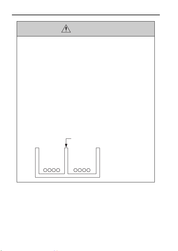
Example of Separated Cables
Power cable
I/O signal
cables in
control circuits
Steel separator
CAUTION
• Select the I/O signal wires for external wiring to connect the Machine Controller to external devices
based on the following criteria:
• Mechanical strength
• Noise interference
• Wiring distance
• Signal voltage
• Separate the I/O signal cables for control circuits
from the power cables both inside and outside the
control panel to reduce the influence of noise from
the power cables.
If the I/O signal lines and power lines are not separated
properly, malfunction may occur.
E-10
Page 13

Operation
CAUTION
• Follow the procedures and instructions in the user’s
manuals for the relevant products to perform normal
operation and trial operation.
Operating mistakes while the Servomotor and machine are
connected may damage the machine or even cause accidents resulting in injury or death.
• Implement interlock signals and other safety circuits
external to the Machine Controller to ensure safety in
the overall system even if the following conditions
occur.
• Machine Controller failure or errors caused by external fac-
tors
• Shutdown of operation due to Machine Controller detection
of an error in self-diagnosis and the subsequent turning OFF
or holding of output signals
• Holding of the ON or OFF status of outputs from the
Machine Controller due to fusing or burning of output relays
or damage to output transistors
• Voltage drops from overloads or short-circuits in the 24-V
output from the Machine Controller and the subsequent
inability to output signals
• Unexpected outputs due to errors in the power supply, I/O, or
memory that cannot be detected by the Machine Controller
through self-diagnosis.
There is a risk of injury, device damage, or burning.
E-11
Page 14

CAUTION
Maintenance and Inspection
CAUTION
• Do not attempt to disassemble or repair the Machine
Controller.
There is a risk of electrical shock, injury, or device damage.
• Do not change any wiring while power is being supplied.
There is a risk of electrical shock, injury, or device damage.
• Do not forget to perform the following tasks when you
replace the CPU Unit:
• Back up all programs and parameters from the CPU Unit that
is being replaced.
• Transfer all saved programs and parameters to the new CPU
Unit.
If you operate the CPU Unit without transferring this data,
unexpected operation may occur. There is a risk of injury
or device damage.
Disposal
• Dispose of the Machine Controller as general industrial waste.
E-12
Page 15

CAUTION
• Observe all local laws and ordinances when you dispose of used Batteries.
Other General Precautions
Observe the following general precautions to
ensure safe application.
• The products shown in the illustrations in this manual
are sometimes shown without covers or protective
guards. Always replace the cover or protective guard
as specified first, and then operate the products in
accordance with the manual.
• The illustrations that are presented in this manual are
typical examples and may not match the product you
received.
• If the manual must be ordered due to loss or damage, inform your nearest Yaskawa representative or
one of the offices listed on the back of this manual.
E-13
Page 16

Warranty
Details of Warranty
Warranty Period
The warranty period for a product that was purchased (hereinafter called “delivered product”) is one year from the time of
delivery to the location specified by the customer or 18 months
from the time of shipment from the Yaskawa factory, whichever is sooner.
Warranty Scope
Yaskawa shall replace or repair a defective product free of
charge if a defect attributable to Yaskawa occurs during the
warranty period above. This warranty does not cover defects
caused by the delivered product reaching the end of its service
life and replacement of parts that require replacement or that
have a limited service life.
This warranty does not cover failures that result from any of
the following causes.
• Improper handling, abuse, or use in unsuitable conditions
or in environments not described in product catalogs or
manuals, or in any separately agreed-upon specifications
• Causes not attributable to the delivered product itself
• Modifications or repairs not performed by Yaskawa
• Abuse of the delivered product in a manner in which it
was not originally intended
E-14
Page 17

• Causes that were not foreseeable with the scientific and
technological understanding at the time of shipment from
Ya sk a wa
• Events for which Yaskawa is not responsible, such as
natural or human-made disasters
Limitations of Liability
• Yaskawa shall in no event be responsible for any damage
or loss of opportunity to the customer that arises due to
failure of the delivered product.
• Yaskawa shall not be responsible for any programs
(including parameter settings) or the results of program
execution of the programs provided by the user or by a
third party for use with programmable Yaskawa products.
• The information described in product catalogs or manuals is provided for the purpose of the customer purchasing the appropriate product for the intended application.
The use thereof does not guarantee that there are no
infringements of intellectual property rights or other proprietary rights of Yaskawa or third parties, nor does it
construe a license.
• Yaskawa shall not be responsible for any damage arising
from infringements of intellectual property rights or
other proprietary rights of third parties as a result of
using the information described in catalogs or manuals.
E-15
Page 18

Suitability for Use
• It is the customer’s responsibility to confirm conformity
with any standards, codes, or regulations that apply if the
Yaskawa product is used in combination with any other
products.
• The customer must confirm that the Yaskawa product is
suitable for the systems, machines, and equipment used
by the customer.
• Consult with Yaskawa to determine whether use in the
following applications is acceptable. If use in the application is acceptable, use the product with extra allowance
in ratings and specifications, and provide safety measures to minimize hazards in the event of failure.
• Outdoor use, use involving potential chemical contamination
or electrical interference, or use in conditions or environments
not described in product catalogs or manuals
• Nuclear energy control systems, combustion systems, railroad
systems, aviation systems, vehicle systems, medical equipment, amusement machines, and installations subject to separate industry or government regulations
• Systems, machines, and equipment that may present a risk to
life or property
• Systems that require a high degree of reliability, such as systems that supply gas, water, or electricity, or systems that operate continuously 24 hours a day
• Other systems that require a similar high degree of safety
E-16
Page 19

• Never use the product for an application involving seri-
ous risk to life or property without first ensuring that the
system is designed to secure the required level of safety
with risk warnings and redundancy, and that the Yaskawa
product is properly rated and installed.
• The circuit examples and other application examples
described in product catalogs and manuals are for reference. Check the functionality and safety of the actual
devices and equipment to be used before using the product.
• Read and understand all use prohibitions and precau-
tions, and operate the Yaskawa product correctly to prevent accidental harm to third parties.
Specifications Change
The names, specifications, appearance, and accessories of
products in product catalogs and manuals may be changed at
any time based on improvements and other reasons. The next
editions of the revised catalogs or manuals will be published
with updated code numbers. Consult with your Yaskawa representative to confirm the actual specifications before purchasing
a product.
E-17
Page 20

Contents
Safety Precautions . . . . . . . . . . . . . . . . . . . . . . . . . . . 1
Warranty. . . . . . . . . . . . . . . . . . . . . . . . . . . . . . . . . . 14
1
Confirmations Upon Delivery . . . . . . . . . 19
Nameplate . . . . . . . . . . . . . . . . . . . . . . . . . . . . . . . . 20
2
Installation . . . . . . . . . . . . . . . . . . . . . . . 21
3
Wiring . . . . . . . . . . . . . . . . . . . . . . . . . . . 23
Wiring Precautions . . . . . . . . . . . . . . . . . . . . . . . . . . 23
4
Inspections . . . . . . . . . . . . . . . . . . . . . . . 28
Daily Inspections . . . . . . . . . . . . . . . . . . . . . . . . . . . 28
Periodic Inspections . . . . . . . . . . . . . . . . . . . . . . . . . 30
Replacement Guidelines for Machine Controller
Parts. . . . . . . . . . . . . . . . . . . . . . . . . . . . . . . . . . . . . 31
5
EMC Standard Compliance . . . . . . . . . . 32
Revision History . . . . . . . . . . . . . . . . . . . 33
E-18
Page 21

1 Confirmations Upon Delivery
1
Confirmations Upon Delivery
Please confirm the following items as soon as you receive the
Machine Controller.
Item Confirmation Method
Have you received the correct
Machine Controller as
ordered?
Is the Machine Controller
damaged in any way?
Check the model number on the
nameplate on the side of the
Machine Controller. Check all
accessories as well.
Check the appearance of the entire
Machine Controller for any damage
that might have occurred during
shipment.
If you find any problems with the above items, contact the
place of purchase or your Yaskawa representative immediately.
E-19
Page 22

1 Confirmations Upon Delivery
cpu
Nameplate
Model number
Version
MAC address
Serial number
/1&'.
8'4
/#%#&&$
+0&%106'3
E-20
Page 23

2
Installation
Refer to the following manual for details on installing the
Machine Controller.
MP2000/MP3000 Series Machine Controller System Setup Manual
(Manual No.: SIEP C880725 00)
Precautions for the installation location are given in the following table.
2 Installation
Installation
Condition
Installation in a
control panel
Installation near
heat-generating
objects
Installation near
sources of vibration
Installation Precautions
• Design the control panel size, Machine Controller location, and cooling method so that
the ambient temperature around the Machine
Controller does not exceed 55°C.
• If you install Machine Controllers side by
side, install a cooling fan above them.
• Provide gaps above and below the Machine
Controller.
Suppress temperature increases due to radiant
heat or convection from the heat-generating
object so that the ambient temperature around
the Machine Controller does not exceed 55°C.
Install a vibration-absorbing device on the
installation surface for the Machine Controller
to prevent vibration from reaching the Machine
Controller.
Continued on next page.
E-21
Page 24

2 Installation
Installation
Installation in
locations subject
to corrosive gas
Others
Condition
Continued from previous page.
Installation Precautions
Take measures to prevent corrosive gas from
entering the Machine Controller. Although the
Machine Controller would not be affected
immediately, the Machine Controller or contact
devices may fail in the future if exposed to corrosive gas.
• Do not install the Machine Controller in locations that are subject to high temperatures or
high humidity, or subject to excessive
amounts of dust, dirt, or iron powder.
• Do not subject the Machine Controller to
freezing or condensation.
• For long-term reliability, use the Machine
Controller at an ambient temperature of 45°C
or less.
E-22
Page 25

3
CAUTION
Wiring
Refer to the following manual for details on connecting the
Machine Controller.
MP2000/MP3000 Series Machine Controller System Setup Manual
(Manual No.: SIEP C880725 00)
Wiring Precautions
Wiring precautions are given below.
• Configure the circuits to turn ON the power
supply to the CPU Unit before the 24-V I/O
power supply.
If the power supply to the CPU Unit is turned ON
after the external power supply, e.g., the 24-V I/O
power supply, the outputs from the CPU Unit may
momentarily turn ON when the power supply to the
CPU Unit turns ON. This can result in unexpected
operation that may cause injury or device damage.
• If you use MECHATROLINK I/O Modules, use
the establishment of MECHATROLINK communications as an interlock output condition.
There is a risk of device damage.
3 Wiring
E-23
Page 26

3 Wiring
cpu
A power-ON sequence and an example circuit configuration
are given below.
Outputs Connected to Relays or Solenoids
Configure circuits that will turn ON the power supply to the
output devices (relays, solenoids, etc.) only after the CPU
RUN output (interlock output) from the CPU Unit turns ON.
<Power-ON Sequence>
Power source to
Power Supply Unit
CPU RUN signal
Power source to
output devices
OFF
OFF
OFF
ON
ON
ON
E-24
Page 27

3 Wiring
cpu
<Example Circuit Configuration>
Power supply
MP3200 and Output Module
Interlock output
SB000004
CPU RUN
OB000000
RA1
Power supply ON relay
for output devices
DC power supply
RA1
DC power supply
Output Module
Output devices
SB000004: Always ON Coil
(ON while the CPU Unit is operating normally.)
OB000000: Interlock output
Note: The MP3200 includes the Power Supply Unit, CPU Unit, and
Base Unit.
The circuit configuration example is for an Output Module added
to the MP3200.
E-25
Page 28

3 Wiring
cpu
Outputs Connected to Other Input and
Output Devices
Connect the CPU RUN output (interlock output) from the
CPU Unit to other input and output devices as an interlock
signal, and confirm that the CPU RUN output from the CPU
Unit is ON before using inputs and outputs on other devices.
The other inputs and outputs are not valid until the CPU RUN
output turns ON.
<Power-ON Sequence>
Power source to
Power Supply Unit
CPU RUN output
Interlock single input to other
input and output devices
Inputs and outputs on
other devices
OFF
OFF
Inputs and outputs are valid.
ON
ON
E-26
Page 29

3 Wiring
cpu
<Example Circuit Configuration>
MP3200 and Output Module
Interlock
SB000004
SB000004: Always ON Coil
(ON while the CPU Unit is operating normally.)
OB000000: Interlock output
output
CPU RUN
OB000000
* Design the circuits so that input and output signals from other input
Other Input and Output Devices
Interlock
signal input
Input and
output signals
and output devices are used only after the interlock signal turns ON.
Note: The MP3200 includes the Power Supply Unit, CPU Unit, and
Base Unit.
The circuit configuration example is for an Output Module added
to the MP3200.
∗
E-27
Page 30

4 Inspections
4
Inspections
Perform inspections and part replacements according to the
information that is provided in this section.
Daily Inspections
The daily inspection items are given in the following table.
Inspection Item Description Criteria Correction
Installation
condition
Connection
conditions
Loose screws
or covers
Loose terminal screws
Connectors
Separation
between
crimped terminals
All screws
and covers
must be
secure.
Screws must
not be loose.
Connectors
must not be
loose.
Suitable gaps
must be maintained.
Continued on next page.
Tighten the
screws.
Tighten the
terminal
screws.
Tighten the
lock screws
on the connectors.
Correct the
gaps.
E-28
Page 31

4 Inspections
Continued from previous page.
Inspection Item Description Criteria Correction
Must be lit.
RDY indicator
Check the
status.
(Otherwise,
there is an
error.)
Must be lit.
(Otherwise,
there is an
error.)
Must not be
lit. (Other-
wise, there is
an error.)
Must not be
lit. (Other-
wise, there is
Refer to the
relevant man-
*
ual.
Indicators
RUN indicator
ALM indicator
ERR indicator
Check the
status in
RUN mode.
Check the
status.
Check the
status.
an error.)
Must not be
BAT indicator
Check the
status.
lit. (Other-
wise, the bat-
Replace the
Battery.
tery is low.)
M_ALM
indicator
Check the
status.
Must not be
lit. (Other-
wise, there is
an axis alarm.)
Refer to the
relevant man-
*
ual.
* MP3000-series MP3200/MP3300 Troubleshooting Manual
(Manual No.: SIEP C880725 01)
E-29
Page 32

4 Inspections
Periodic Inspections
Perform the following inspections at least once a year.
*
Inspection
Period
At least 1 or 2
times every 6
to 12 months
At least 1 time
a year
Description Correction
Measure the
temperature and
humidity with a
hydrometer and
thermometer and
measure corrosive gas. They
must be within
specifications.
There must be
no dirt, dust, oil,
or other foreign
matter on the
Machine Controller.
There must be
no looseness in
terminal screws
or connector
lock screws.
Inspection Item
Ambient
tempera-
ture
Ambient
Ambient
condi-
humidity
tions
Atmosphere
Vis ua l ex ter ior
inspection
Loose screws
Remove
sources of
contamination or
improve the
installation
environment.
Clean the
Machine
Controller
with air or a
cloth.
Tighten the
screws.
E-30
* If the Machine Controller is installed in a panel, the temperature
inside the panel is the ambient temperature.
Page 33

4 Inspections
Replacement Guidelines for Machine Controller Parts
Electrical and electronic parts have a limited service life due
to mechanical wear and deterioration over time. Perform periodic inspections for preventive maintenance.
Contact your Yaskawa representative for replacements based
on the standard replacement periods that are given in the following table. Yaskawa will inspect your Machine Controller
and determine if part replacement is required.
Yaskawa will initialize the settings of all parameters to the
default values in Machine Controllers that are returned for
overhaul. Before you start operation again, make sure that you
reset the parameters that are required for operation.
Standard
Part Name
Battery
FAN 5 years
Replacement
Period
3 years
2 years
*
*
Application Conditions
• Ambient temperature:
55°C or less
• Operation: 16 hours/day
• Ambient temperature:
55°C or less
• Operation: 12 hours/day
Ambient temperature:
40°C or less
* Replace the Battery when the total time that the product is not in
operation reaches 1 year (8,760 hours).
E-31
Page 34

5 EMC Standard Compliance
5
EMC Standard Compliance
The Machine Controller complies with the following EMC
standards: EN 55011 group 1 class A, EN 61000-6-2, and EN
61000-6-4. However, the Machine Controller is an electric
device that is used as part of a machine or manufacturing
equipment. Therefore, the EMC performance will also depend
on the configuration of the actual system, wiring conditions,
and other conditions. It is the user’s responsibility to confirm
EMC standard compliance for the overall machine or equipment.
E-32
Page 35

Revision History
MANUAL NO.
TOMP C880725 16A
<1>
Published in Japan
November 2014
Date of publication
Revision number
cpu
The revision dates and numbers of the revised manuals are given on
the bottom of the back cover.
Date of
Publication
May 2015 <2>
November 2014 <1>
September 2014 −
Rev.
Section Revised Contents
No.
Front cover,
back cover
Back cover Revision: Address
− First edition
Revision: Format
E-33
Page 36

Machine Controller MP3000 Series
MP3200 CPU Unit
INSTRUCTIONS
IRUMA BUSINESS CENTER (SOLUTION CENTER)
480, Kamifujisawa, Iruma, Saitama, 358-8555, Japan
Phone 81-4-2962-5151 Fax 81-4-2962-6138
http://www.yaskawa.co.jp
YASKAWA AMERICA, INC.
2121, Norman Drive South, Waukegan, IL 60085, U.S.A.
Phone 1-800-YASKAWA (927-5292) or 1-847-887-7000 Fax 1-847-887-7310
http://www.yaskawa.com
YASKAWA ELÉTRICO DO BRASIL LTDA.
777, Avenida Piraporinha, Diadema, São Paulo, 09950-000, Brasil
Phone 55-11-3585-1100 Fax 55-11-3585-1187
http://www.yaskawa.com.br
YASKAWA EUROPE GmbH
185, Hauptstraβe, Eschborn, 65760, Germany
Phone 49-6196-569-300 Fax 49-6196-569-398
http://www.yaskawa.eu.com
YASKAWA ELECTRIC KOREA CORPORATION
9F, Kyobo Securities Bldg. 26-4, Yeouido-dong, Yeongdeungpo-gu, Seoul, 150-737, Korea
Phone 82-2-784-7844 Fax 82-2-784-8495
http://www.yaskawa.co.kr
YASKAWA ELECTRIC (SINGAPORE) PTE. LTD.
151, Lorong Chuan, #04-02A, New Tech Park, 556741, Singapore
Phone 65-6282-3003 Fax 65-6289-3003
http://www.yaskawa.com.sg
YASKAWA ELECTRIC (THAILAND) CO., LTD.
252/125-126, 27th Floor, Muang Thai-Phatra Tower B, Rachadapisek Road, Huaykwang, Bangkok, 10310, Thailand
Phone 66-2693-2200 Fax 66-2693-4200
http://www.yaskawa.co.th
YASKAWA ELECTRIC (CHINA) CO., LTD.
22F, One Corporate Avenue, No.222, Hubin Road, Shanghai, 200021, China
Phone 86-21-5385-2200 Fax 86-21-5385-3299
http://www.yaskawa.com.cn
YASKAWA ELECTRIC (CHINA) CO., LTD. BEIJING OFFICE
Room 1011, Tower W3 Oriental Plaza, No.1, East Chang An Ave.,
Dong Cheng District, Beijing, 100738, China
Phone 86-10-8518-4086 Fax 86-10-8518-4082
YASKAWA ELECTRIC TAIWAN CORPORATION
9F, 16, Nanking E. Rd., Sec. 3, Taipei, 104, Taiwan
Phone 886-2-2502-5003 Fax 886-2-2505-1280
In the event that the end user of this product is to be the military and said product is
to be employed in any weapons systems or the manufacture thereof, the export will
fall under the relevant regulations as stipulated in the Foreign Exchange and Foreign
Trade Regulations. Therefore, be sure to follow all procedures and submit all relevant
documentation according to any and all rules, regulations and laws that may apply.
Specifications are subject to change without notice for ongoing product modifications
and improvements.
© 2014-2015 YASKAWA ELECTRIC CORPORATION
MANUAL NO. TOMP C880725 16A <2>-0
Published in Japan May 2015
14-9-10
Page 37

한국 전파법에 관한 주의사항
韓国電波法に関連する注意事項
Precautions for Korean Radio Waves Act
针对韩国电波法的注意事项
Précautions pour la Loi coréenne relative aux ondes radio
사용자 안내문
기종별 사용자 안내문
A급 기기
( 업무용 방송
통신기 자재 )
이 기기는 업무용 (A 급 ) 전자파 적합 기기로서 판매자
또는 , 사용자는 이 점을 주의하시기 바라며 , 가정외의
지역에서 사용하는 것을 목적으로 합니다 .
 Loading...