

Page 1

Machine Controller MP2000 Series
263IF-01
EtherNet/IP Communication Module
USER'S MANUAL
Model: JAPMC-CM2304-E
263IF-01
MS
NS
IP
RX
TX
INIT
TEST
EtherNet/IP
LINK
100M
NO
ONOFF
EtherNet/IP Communication
263IF-01 Module
Mounting and Starting the Module
EtherNet/IP Transmission Definition
Explicit Message and Explicit Message Send Function
Troubleshooting
Appendices
1
2
3
4
5
6
App
MANUAL NO. SIEP C880700 39A
Page 2

Copyright © 2008 YASKAWA ELECTRIC CORPORATION
All rights reserved. No part of this publication may be reproduced, stored in a retrieval system, or
transmitted, in any form, or by any means, mechanical, electronic, photocopying, recording, or otherwise, without the prior written permission of Yaskawa. No patent liability is assumed with respect to
the use of the information contained herein. Moreover, because Yaskawa is constantly striving to
improve its high-quality products, the information contained in this manual is subject to change without
notice. Every precaution has been taken in the preparation of this manual. Nevertheless, Yaskawa
assumes no responsibility for errors or omissions. Neither is any liability assumed for damages resulting from the use of the information contained in this publication.
Page 3

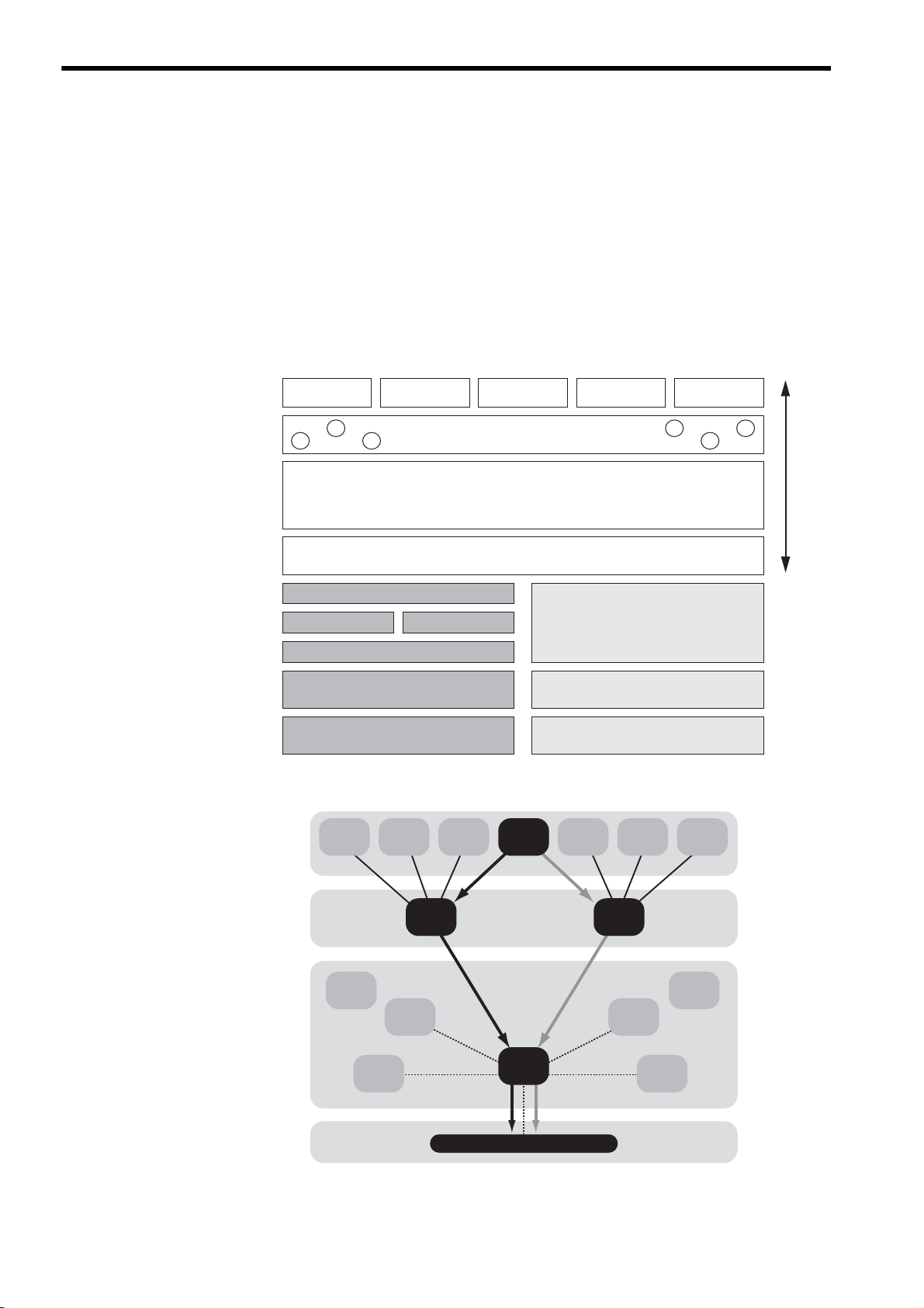
Purpose
Chapter
Selecting
Models and
Peripheral
Devices
Studying
Specifications
and Ratings
Designing
the
System
Panel
Installation
and Wiring
Tria l
Operation
Maintenance
and
Inspection
Chapter 1 EtherNet/IP
Communication
99
Chapter 2 263IF-01 Module 9 9 999 9
Chapter 3 Mounting and Starting
the Module
9 999 9
Chapter 4 EtherNet/IP
Transmission
Definition
99 99
Chapter 5 Explicit Message and
Explicit Message
Send Function
99
Chapter 6 Troubleshooting 9 999 9
This symbol is used to indicate important information that should be memorized or minor precautions,
such as precautions that will result in alarms if not heeded.
S-ON = /S-ON
P-CON
=
/P-CON
Using this Manual
This manual describes EtherNet/IP Communication Module 263IF-01 for the MP2000-series Machine Controller.
Read this manual thoroughly before using the 263IF-01. Keep this manual in a safe place for future reference.
Basic Terms
Unless otherwise specified, the following definitions are used:
• MP2000-series Machine Controllers: MP2100M, MP2200, MP2300, MP2310, MP2300S, and MP2500MD
Machine Controllers
• PLC: Programmable Logic Controller
• MPE720: The Programming Device Software or a personal computer running the Programming Device Software
Manual Configuration
This manual consists of the chapters listed in the following table. Read the chapters of this manual as required by the
purpose.
Graphic Symbols Used in this Manual
The graphic symbols used in this manual indicate the following type of information.
Indication of Reverse Signals
In this manual, the names of reverse signals (ones that are valid when low) are written with a forward slash (/) before
the signal name, as shown in the following example:
<Notation Examples>
iii
Page 4

Related Manuals
The following table lists the manuals relating to the 263IF-01 Module for the MP2000-series Machine Controller.
Refer to these manuals as needed.
Manual Name Manual Number Contents
Machine Controller MP2100/MP2100M
User's Manual
Design and Maintenance
Machine Controller MP2200
User's Manual
Machine Controller MP2300
Basic Module User's Manual
Machine Controller MP2310
Basic Module User's Manual
Machine Controller MP2300S
Basic Module User's Manual
Machine Controller
MP2500/MP2500M/MP2500D/MP2500MD
User's Manual
Machine Controller MP2000 Series
Motion Module Built-in SVB/SVB-01
User's Manual
Machine Controller MP2000 Series
Communication Module User's Manual
Machine Controller MP2000 Series
262IF-01 FL-net Communication Module
User's Manual
Machine Controller MP900/MP2000 Series
User's Manual: Ladder Programming
Machine Controller MP900/MP2000 Series
User's Manual: Motion Programming
Machine Controller MP2000 Series
MPE720 Programming Device Version 6
User's Manual
Machine Controller MP900/MP2000 Series
MPE720 Software for Programming Device
User's Manual
Machine Controller MP900/MP2000 Series
New Ladder Editor Programming Manual
Machine Controller MP900/MP2000 Series
New Ladder Editor User's Manual
Machine Controller MP920
User's Manual
Communication Modules
SIEPC88070001
SIEPC88070014
SIEPC88070003
SIEPC88073201
SIEPC88073200
SIEPC88075200
SIEPC88070033
SIEPC88070004
SIEPC88070036
SIEZ-C887-1.2
SIEZ-C887-1.3
SIEPC880700 30
SIEPC88070005
SIEZ-C887-13.1
SIEZ-C887-13.2
SIEZ-C887-2.6
Describes how to use the MP2100 and MP2100M
Machine Controllers.
Describes how to use the MP2200 Machine Controller and the modules that can be connected.
Describes how to use the MP2300 Basic Module
and the modules that can be connected.
Describes how to use the MP2310 Basic Module
and the modules that can be connected.
Describes how to use the MP2300S Basic Module
and the modules that can be connected.
Describes how to use the MP2500, MP2500M,
MP2500D, and MP2500MD Machine Controllers.
Provides a detailed description on the MP2000
Series Machine Controller built-in SVB Module
and slot-mounting optional SVB-01 Module.
Provides the information on the Communication
Module that can be connected to MP2000 Series
Machine Controller and the communication methods.
Provides a detailed description of the FL-net Communication Module 262IF-01 that can be connected
to an MP2000-series Machine Controller.
Describes the instructions used in MP900/MP2000
ladder programming.
Describes the instructions used in MP900/MP2000
motion programming.
Describes how to install and operate the programming tool MPE720 version 6 for MP2000 Series
Machine Controllers.
Describes how to install and operate the MP900/
MP2000 Series programming system (MPE720).
Describes the programming instructions of the New
Ladder Editor, which assists MP900/MP2000
Series design and maintenance.
Describes the operating methods of the New Ladder
Editor, which assists design and maintenance of the
MP900/MP2000 series Machine Controllers.
Describes the functions, specifications, and application methods of the MP920 Communication Modules (217IF, 215IF, and 218IF).
iv
Copyrights
EtherNet/IP and DeviceNet are registered trademarks of the ODVA (Open DeviceNet Vendor Association Inc.).
Ethernet is a registered trademark of the Xerox Corporation.
Other product names and company names are the trademarks or registered trademarks of the respective company.
“TM” and the
® mark do not appear with product or company names in this manual.
Page 5
WARNING
CAUTION
CAUTION
PROHIBITED
MANDATORY
●
Safety Information
The following conventions are used to indicate precautions in this manual. Information marked as shown below is
important for the safety of the user. Always read this information and heed the precautions that are provided. The conventions are as follows:
Indicates precautions that, if not heeded, could possibly result in loss of life or serious
injury.
Indicates precautions that, if not heeded, could result in relatively serious or minor
injury, or property damage.
If not heeded, even precautions classified under can lead to serious results
depending on circumstances.
Indicates prohibited actions. Specific prohibitions are indicated inside .
For example, indicates no fire or open flame.
Indicates mandatory actions. Specific actions are indicated inside .
For example, indicates that grounding is required.
Safety Precautions
The following precautions are for checking products on delivery, storage, transportation, installation, wiring, operation,
application, inspection, and disposal. These precautions are important and must be observed.
General Precautions
WARNING
Before starting operation while connected to the machine, ensure that an emergency stop procedure has
been provided and is working correctly.
There is a risk of injury.
Do not touch anything inside the product.
There is a risk of electrical shock.
Always keep the front cover attached when power is being supplied.
There is a risk of electrical shock.
Observe all procedures and precautions given in this manual for trial operation.
Operating mistakes while the Servomotor and machine are connected can cause damage to the machine or even accidents resulting in injury or death.
Do not remove the front cover, cables, connector, or options while power is being supplied.
There is a risk of electrical shock.
Do not damage, pull on, apply excessive force to, place heavy objects on, or pinch cables.
There is a risk of electrical shock, operational failure of the product, or burning.
Do not attempt to modify the product in any way.
There is a risk of injury or device damage.
Do not approach the machine when there is a momentary interruption to the power supply. When power is
restored, the MP2000-series Machine Controller or machine connected to it may start operation suddenly.
Provide suitable safety measures to protect people when operation restarts.
There is a risk of injury.
Do not allow installation, disassembly, or repairs to be performed by anyone other than specified person-
nel.
There is a risk of electrical shock or injury.
v
Page 6
CAUTION
CAUTION
Storage and Transportation
Do not store or install the product in locations subject to the following. There is a risk of fire, electric shock,
and machine product damage.
Direct sunlight
Ambient temperatures exceeding the storage or operating conditions
Ambient humidity exceeding the storage or operating conditions
Extreme changes in temperature that would result in condensation
Corrosive or flammable gas
Excessive dust, dirt, salt, or metallic powder
Water, oil, or chemicals
Vibration or shock
Do not overload the product during transportation.
There is a risk of injury or an accident.
Never subject the product to an atmosphere containing halogen (fluorine, chlorine, bromine, or iodine) dur-
ing transportation or installation.
There is a risk of device damage or an accident.
If disinfectants or insecticides must be used to treat packing materials such as wooden frames, pallets, or
plywood, the packing materials must be treated before the product is packaged, and methods other than
fumigation must be used.
Example: Heat treatment, where materials are kiln-dried to a core temperature of 56°C
for 30 minutes or more.
If the electronic products, which include stand-alone products and products installed in machines, are packed with
fumigated wooden materials, the electrical components may be greatly damaged by the gases or fumes resulting from
the fumigation process. In particular, disinfectants containing halogen, which includes chlorine, fluorine, bromine, or
iodine can contribute to the erosion of the capacitors.
Installation
Never use the product in locations subject to water, corrosive atmospheres, or flammable gas, or near
burnable objects.
There is a risk of electrical shock or fire.
Do not step on the product or place heavy objects on the product.
There is a risk of injury.
Do not block the air exhaust port on the product. Do not allow foreign objects to enter the product.
There is a risk of element deterioration inside, an accident, or fire.
Always mount the product in the specified orientation.
There is a risk of an accident.
Do not subject the product to strong shock.
There is a risk of an accident.
vi
Page 7
CAUTION
CAUTION
CAUTION
Wiring
Check the wiring to be sure it has been performed correctly.
There is a risk of motor run-away, injury, or an accident.
Always use a power supply of the specified voltage.
There is a risk of burning.
In places with poor power supply conditions, take all steps necessary to ensure that the input power is sup-
plied within the specified voltage range.
There is a risk of device damage.
Install breakers and other safety measures to provide protection against shorts in external wiring.
There is a risk of fire.
Provide sufficient shielding when using the product in the locations subject to the following.
There is a risk of device damage.
Noise, such as from static electricity
Strong electromagnetic or magnetic fields
Radiation
Near power lines
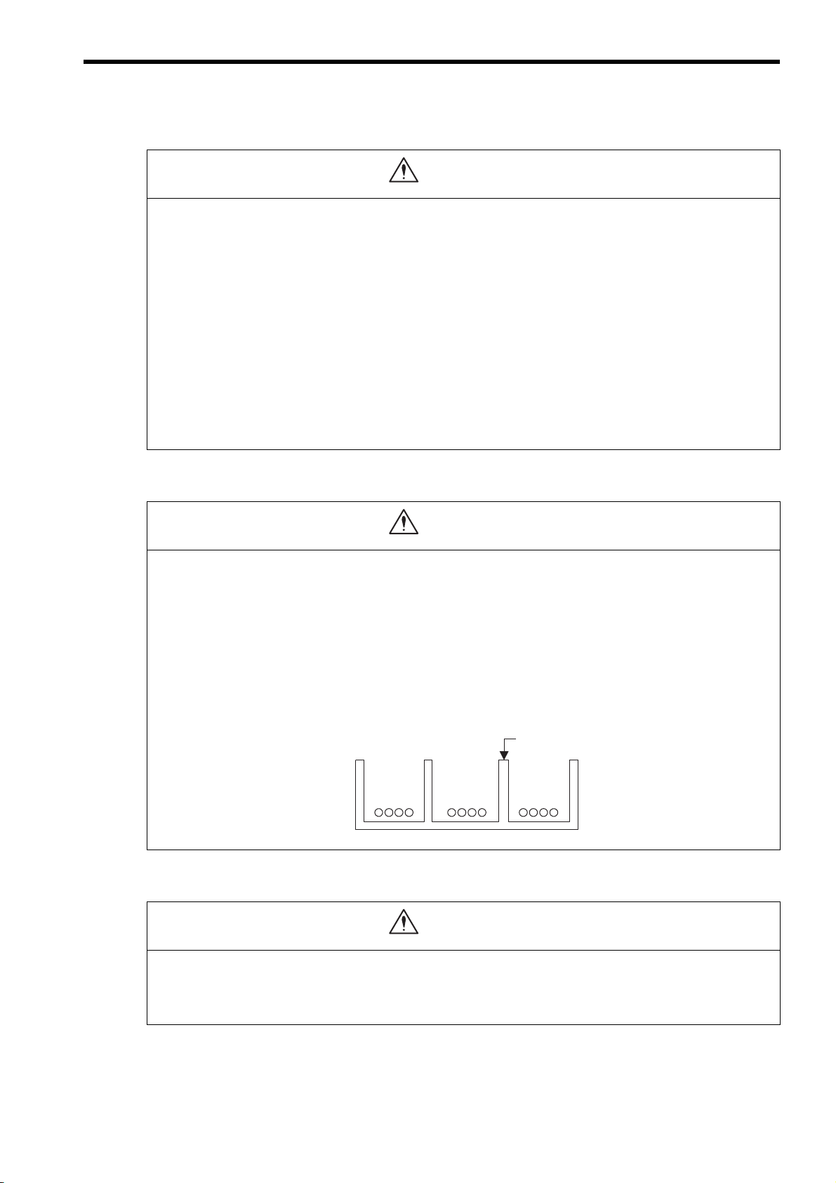
Selecting, Separating, and Laying External Cables
Consider the following items when selecting the I/O signal lines (external cables) to connect the product to
external devices.
Mechanical strength
Noise interference
Wiring distance
Signal voltage, etc.
Separate the I/O signal lines from the power lines both inside and outside the control box to reduce the
influence of noise from the power lines.
If the I/O signal lines and power lines are not separated properly, malfunctioning may result.
Example of Separated External Cables
Power circuit
cables
General
control circuit
cables
Maintenance and Inspection Precautions
Steel separator
Digital I/O
signal cables
Do not attempt to disassemble the product.
There is a risk of electrical shock or injury.
Do not change wiring while power is being supplied.
There is a risk of electrical shock or injury.
vii
Page 8

CAUTION
Disposal Precautions
Dispose of the product as general industrial waste.
General Precautions
Observe the following general precautions
to ensure safe application.
The products shown in illustrations in this manual are sometimes shown without covers or protective
guards. Always replace the cover or protective guard as specified first, and then operate the products in
accordance with the manual.
The drawings presented in this manual are typical examples and may not match the product you
received.
If the manual must be ordered due to loss or damage, inform your nearest Yaskawa representative or
one of the offices listed on the back of this manual.
viii
Page 9

Warranty
( 1 ) Details of Warranty
Warranty Period
The warranty period for a product that was purchased (hereinafter called “delivered product”) is one year from the time
of delivery to the location specified by the customer or 18 months from the time of shipment from the Yaskawa factory,
whichever is sooner.
Warranty Scope
Yaskawa shall replace or repair a defective product free of charge if a defect attributable to Yaskawa occurs during the
warranty period above. This warranty does not cover defects caused by the delivered product reaching the end of its
service life and replacement of parts that require replacement or that have a limited service life.
This warranty does not cover failures that result from any of the following causes.
1. Improper handling, abuse, or use in unsuitable conditions or in environments not described in product catalogs or
manuals, or in any separately agreed-upon specifications
2. Causes not attributable to the delivered product itself
3. Modifications or repairs not performed by Yaskawa
4. Abuse of the delivered product in a manner in which it was not originally intended
5. Causes that were not foreseeable with the scientific and technological understanding at the time of shipment from
Ya sk a wa
6. Events for which Yaskawa is not responsible, such as natural or human-made disasters
( 2 ) Limitations of Liability
1. Yaskawa shall in no event be responsible for any damage or loss of opportunity to the customer that arises due to
failure of the delivered product.
2. Yaskawa shall not be responsible for any programs (including parameter settings) or the results of program execu-
tion of the programs provided by the user or by a third party for use with programmable Yaskawa products.
3. The information described in product catalogs or manuals is provided for the purpose of the customer purchasing
the appropriate product for the intended application. The use thereof does not guarantee that there are no infringements of intellectual property rights or other proprietary rights of Yaskawa or third parties, nor does it construe a
license.
4. Yaskawa shall not be responsible for any damage arising from infringements of intellectual property rights or other
proprietary rights of third parties as a result of using the information described in catalogs or manuals.
ix
Page 10

( 3 ) Suitability for Use
1. It is the customer’s responsibility to confirm conformity with any standards, codes, or regulations that apply if the
Yaskawa product is used in combination with any other products.
2. The customer must confirm that the Yaskawa product is suitable for the systems, machines, and equipment used by
the customer.
3. Consult with Yaskawa to determine whether use in the following applications is acceptable. If use in the application
is acceptable, use the product with extra allowance in ratings and specifications, and provide safety measures to
minimize hazards in the event of failure.
• Outdoor use, use involving potential chemical contamination or electrical interference, or use in conditions or
environments not described in product catalogs or manuals
• Nuclear energy control systems, combustion systems, railroad systems, aviation systems, vehicle systems,
medical equipment, amusement machines, and installations subject to separate industry or government regulations
• Systems, machines, and equipment that may present a risk to life or property
• Systems that require a high degree of reliability, such as systems that supply gas, water, or electricity, or systems that operate continuously 24 hours a day
• Other systems that require a similar high degree of safety
4. Never use the product for an application involving serious risk to life or property without first ensuring that the system is designed to secure the required level of safety with risk warnings and redundancy, and that the Yaskawa
product is properly rated and installed.
5. The circuit examples and other application examples described in product catalogs and manuals are for reference.
Check the functionality and safety of the actual devices and equipment to be used before using the product.
6. Read and understand all use prohibitions and precautions, and operate the Yaskawa product correctly to prevent
accidental harm to third parties.
( 4 ) Specifications Change
The names, specifications, appearance, and accessories of products in product catalogs and manuals may be changed at
any time based on improvements and other reasons. The next editions of the revised catalogs or manuals will be published with updated code numbers. Consult with your Yaskawa representative to confirm the actual specifications
before purchasing a product.
x
Page 11

Contents
Using this Manual - - - - - - - - - - - - - - - - - - - - - - - - - - - - - - - - - - - - - - - - - - - - - - - - - - - - - - - iii
Safety Information - - - - - - - - - - - - - - - - - - - - - - - - - - - - - - - - - - - - - - - - - - - - - - - - - - - - - - - v
Safety Precautions - - - - - - - - - - - - - - - - - - - - - - - - - - - - - - - - - - - - - - - - - - - - - - - - - - - - - - v
Warranty - - - - - - - - - - - - - - - - - - - - - - - - - - - - - - - - - - - - - - - - - - - - - - - - - - - - - - - - - - - - - ix
1 EtherNet/IP Communication - - - - - - - - - - - - - - - - - - - - - - - - - - - - - - - - - - - - 1-1
1.1 What is EtherNet/IP? - - - - - - - - - - - - - - - - - - - - - - - - - - - - - - - - - - - - - - - - - 1-2
1.2 EtherNet/IP Features - - - - - - - - - - - - - - - - - - - - - - - - - - - - - - - - - - - - - - - - - 1-3
1.3 EtherNet/IP (CIP) Communication Types - - - - - - - - - - - - - - - - - - - - - - - - - - - 1-4
1.3.1 Explicit Message Communication - - - - - - - - - - - - - - - - - - - - - - - - - - - - - - - - - - - - - - - - - - - 1-4
1.3.2 I/O Communication - - - - - - - - - - - - - - - - - - - - - - - - - - - - - - - - - - - - - - - - - - - - - - - - - - - - - 1-4
2 263IF-01 Module - - - - - - - - - - - - - - - - - - - - - - - - - - - - - - - - - - - - - - - - - - - - 2-1
2.1 Features - - - - - - - - - - - - - - - - - - - - - - - - - - - - - - - - - - - - - - - - - - - - - - - - - - 2-2
2.1.1 I/O Communication - - - - - - - - - - - - - - - - - - - - - - - - - - - - - - - - - - - - - - - - - - - - - - - - - - - - - 2-2
2.1.2 Explicit Message Communication - - - - - - - - - - - - - - - - - - - - - - - - - - - - - - - - - - - - - - - - - - - 2-3
2.1.3 Engineering Communication- - - - - - - - - - - - - - - - - - - - - - - - - - - - - - - - - - - - - - - - - - - - - - - 2-4
2.2 Specifications- - - - - - - - - - - - - - - - - - - - - - - - - - - - - - - - - - - - - - - - - - - - - - - 2-5
2.2.1 Hardware Specifications- - - - - - - - - - - - - - - - - - - - - - - - - - - - - - - - - - - - - - - - - - - - - - - - - - 2-5
2.2.2 Transmission Specifications - - - - - - - - - - - - - - - - - - - - - - - - - - - - - - - - - - - - - - - - - - - - - - - 2-6
2.2.3 Software Configuration- - - - - - - - - - - - - - - - - - - - - - - - - - - - - - - - - - - - - - - - - - - - - - - - - - - 2-8
2.2.4 Operating Environment Specifications - - - - - - - - - - - - - - - - - - - - - - - - - - - - - - - - - - - - - - - 2-9
2.3 Overview - - - - - - - - - - - - - - - - - - - - - - - - - - - - - - - - - - - - - - - - - - - - - - - - - - 2-10
2.3.1 Appearance and Connectors - - - - - - - - - - - - - - - - - - - - - - - - - - - - - - - - - - - - - - - - - - - - - 2-10
2.3.2 Status Indicators (LEDs)- - - - - - - - - - - - - - - - - - - - - - - - - - - - - - - - - - - - - - - - - - - - - - - - - 2-10
2.3.3 Communication Status Indicators (LEDs) (Contained in the Ethernet Connector)- - - - - - - - - 2-11
2.3.4 Switch Settings - - - - - - - - - - - - - - - - - - - - - - - - - - - - - - - - - - - - - - - - - - - - - - - - - - - - - - 2-11
2.4 Connection Specifications - - - - - - - - - - - - - - - - - - - - - - - - - - - - - - - - - - - - - - 2-12
2.4.1 Connector Specifications - - - - - - - - - - - - - - - - - - - - - - - - - - - - - - - - - - - - - - - - - - - - - - - - 2-12
2.4.2 Cable Specifications - - - - - - - - - - - - - - - - - - - - - - - - - - - - - - - - - - - - - - - - - - - - - - - - - - - 2-12
3 Mounting and Starting the Module - - - - - - - - - - - - - - - - - - - - - - - - - - - - - - - - 3-1
3.1 Applicable Machine Controllers and Supported Versions - - - - - - - - - - - - - - - - 3-2
3.1.1 Applicable Machine Controllers- - - - - - - - - - - - - - - - - - - - - - - - - - - - - - - - - - - - - - - - - - - - - 3-2
3.1.2 Supported CPU and MPE720 Versions - - - - - - - - - - - - - - - - - - - - - - - - - - - - - - - - - - - - - - - 3-2
3.2 Mounting and Removing a Module on the Machine Controller- - - - - - - - - - - - - 3-3
3.2.1 Mounting a 263IF-01 Module - - - - - - - - - - - - - - - - - - - - - - - - - - - - - - - - - - - - - - - - - - - - - - 3-3
3.2.2 Removing a 263IF-01 Module- - - - - - - - - - - - - - - - - - - - - - - - - - - - - - - - - - - - - - - - - - - - - - 3-6
3.3 Setting the Communication Manager - - - - - - - - - - - - - - - - - - - - - - - - - - - - - - 3-8
3.3.1 Preparation of the Personal Computer- - - - - - - - - - - - - - - - - - - - - - - - - - - - - - - - - - - - - - - - 3-8
3.3.2 Setting the Communication Manager- - - - - - - - - - - - - - - - - - - - - - - - - - - - - - - - - - - - - - - - 3-10
3.4 Self-configuration - - - - - - - - - - - - - - - - - - - - - - - - - - - - - - - - - - - - - - - - - - - - 3-14
3.4.1 Executing Self-configuration - - - - - - - - - - - - - - - - - - - - - - - - - - - - - - - - - - - - - - - - - - - - - - 3-14
xi
Page 12

3.5 Starting the MPE720, and Setting Communication or Network Parameters - - - 3-15
3.5.1 Starting MPE720 Ver. 6 and Setting Communication Parameters - - - - - - - - - - - - - - - - - - - 3-15
3.5.2 Starting MPE720 Ver. 5.xx and Setting Network Parameters- - - - - - - - - - - - - - - - - - - - - - - 3-16
4 EtherNet/IP Transmission Definition - - - - - - - - - - - - - - - - - - - - - - - - - - - - - - 4-1
4.1 Displaying the EtherNet/IP Transmission Configuration Window - - - - - - - - - - - - 4-2
4.1.1 Displaying the Module Configuration Window - - - - - - - - - - - - - - - - - - - - - - - - - - - - - - - - - - 4-2
4.1.2 Displaying the EtherNet/IP Transmission Configuration Window
from the Module Configuration Window - - - - - - - - - - - - - - - - - - - - - - - - - - - - - - - - - - - - - - 4-3
4.2 EtherNet/IP Transmission Definition - - - - - - - - - - - - - - - - - - - - - - - - - - - - - - - - 4-4
4.2.1 Network Parameter Tab Page - - - - - - - - - - - - - - - - - - - - - - - - - - - - - - - - - - - - - - - - - - - - - 4-4
4.2.2 Connection List Tab Page - - - - - - - - - - - - - - - - - - - - - - - - - - - - - - - - - - - - - - - - - - - - - - - - 4-6
4.2.3 IO Communication Detail Setting Window - - - - - - - - - - - - - - - - - - - - - - - - - - - - - - - - - - - - 4-10
4.2.4 NetWork Configuration Search Window - - - - - - - - - - - - - - - - - - - - - - - - - - - - - - - - - - - - - 4-11
4.2.5 Status Detail Window - - - - - - - - - - - - - - - - - - - - - - - - - - - - - - - - - - - - - - - - - - - - - - - - - - 4-12
4.2.6 I/O Status Tab Page - - - - - - - - - - - - - - - - - - - - - - - - - - - - - - - - - - - - - - - - - - - - - - - - - - - 4-13
4.2.7 Status Detail Window - - - - - - - - - - - - - - - - - - - - - - - - - - - - - - - - - - - - - - - - - - - - - - - - - - 4-14
4.2.8 Module Information Tab Page - - - - - - - - - - - - - - - - - - - - - - - - - - - - - - - - - - - - - - - - - - - - 4-16
5 Explicit Message and Explicit Message Send Function - - - - - - - - - - - - - - - - - 5-1
5.1 Explicit Messages- - - - - - - - - - - - - - - - - - - - - - - - - - - - - - - - - - - - - - - - - - - - - 5-2
5.1.1 Explicit Request Message - - - - - - - - - - - - - - - - - - - - - - - - - - - - - - - - - - - - - - - - - - - - - - - - 5-2
5.1.2 Explicit Response Message- - - - - - - - - - - - - - - - - - - - - - - - - - - - - - - - - - - - - - - - - - - - - - - 5-3
5.2 Message Send Function - - - - - - - - - - - - - - - - - - - - - - - - - - - - - - - - - - - - - - - - 5-4
5.2.1 Outline Specifications - - - - - - - - - - - - - - - - - - - - - - - - - - - - - - - - - - - - - - - - - - - - - - - - - - - 5-4
5.2.2 MSG-SND Function Setting Example - - - - - - - - - - - - - - - - - - - - - - - - - - - - - - - - - - - - - - - - 5-5
5.2.3 Inputs and Outputs for the Message Send Function - - - - - - - - - - - - - - - - - - - - - - - - - - - - - - 5-5
5.2.4 Parameter List for MSG-SND Function - - - - - - - - - - - - - - - - - - - - - - - - - - - - - - - - - - - - - - 5-10
5.2.5 Details of Parameters Used in Explicit Message - - - - - - - - - - - - - - - - - - - - - - - - - - - - - - - 5-11
5.3 Displaying a Register List and Notes at Register Input - - - - - - - - - - - - - - - - - - 5-14
5.3.1 Displaying a Register List - - - - - - - - - - - - - - - - - - - - - - - - - - - - - - - - - - - - - - - - - - - - - - - 5-14
5.3.2 Notes at Register Input - - - - - - - - - - - - - - - - - - - - - - - - - - - - - - - - - - - - - - - - - - - - - - - - - 5-16
5.4 Programming Example - - - - - - - - - - - - - - - - - - - - - - - - - - - - - - - - - - - - - - - - 5-17
5.4.1 Procedure to Start Communication - - - - - - - - - - - - - - - - - - - - - - - - - - - - - - - - - - - - - - - - - 5-17
5.4.2 Programming Example - - - - - - - - - - - - - - - - - - - - - - - - - - - - - - - - - - - - - - - - - - - - - - - - - 5-18
6 Troubleshooting - - - - - - - - - - - - - - - - - - - - - - - - - - - - - - - - - - - - - - - - - - - - 6-1
6.1 Status Indication by LED Indicators - - - - - - - - - - - - - - - - - - - - - - - - - - - - - - - - 6-2
6.2 System I/O Error Status- - - - - - - - - - - - - - - - - - - - - - - - - - - - - - - - - - - - - - - - - 6-3
6.2.1 System I/O Error Status by Controllers - - - - - - - - - - - - - - - - - - - - - - - - - - - - - - - - - - - - - - - 6-3
6.2.2 Details on I/O Error Status - - - - - - - - - - - - - - - - - - - - - - - - - - - - - - - - - - - - - - - - - - - - - - - - 6-7
xii
Appendices - - - - - - - - - - - - - - - - - - - - - - - - - - - - - - - - - - - - - - - - - - - - - - - - A-1
Appendix A Details of Status Codes- - - - - - - - - - - - - - - - - - - - - - - - - - - - - - - - - - A-2
A.1 General Status Code Table - - - - - - - - - - - - - - - - - - - - - - - - - - - - - - - - - - - - - - - - - - - - - - - - A-2
A.2 Extended Status Code Table - - - - - - - - - - - - - - - - - - - - - - - - - - - - - - - - - - - - - - - - - - - - - - - A-3
Index
Revision History
Page 13

1
EtherNet/IP Communication
1
EtherNet/IP Communication
This chapter gives an overview of EtherNet/IP communication.
1.1 What is EtherNet/IP? - - - - - - - - - - - - - - - - - - - - - - - - - - - - - - - - - - - - - -1-2
1.2 EtherNet/IP Features - - - - - - - - - - - - - - - - - - - - - - - - - - - - - - - - - - - - - -1-3
1.3 EtherNet/IP (CIP) Communication Types - - - - - - - - - - - - - - - - - - - - - - - - 1-4
1.3.1 Explicit Message Communication - - - - - - - - - - - - - - - - - - - - - - - - - - - - - - - - - - - - - - 1-4
1.3.2 I/O Communication - - - - - - - - - - - - - - - - - - - - - - - - - - - - - - - - - - - - - - - - - - - - - - - - 1-4
1-1
Page 14
1.1 What is EtherNet/IP?
SemiconductorDevice profile
Transport
Network
Data link
Physical media
Application
Encapsulation
IP
Ethernet
CSMA/CD
Ethernet
Physical Layer
CAN
CSMA/CD
DeviceNet
Transport
DeviceNet
Physical Layer
TCP UDP
CIP application layer
Application object library
CIP message routing, connection control
CIP data management service
Explicit messages, I/O messages
CIP
Valve Drive Robot Others
Application layer
Transport layer
Network layer
Data link layer
Physical layer
Explicit messages
I/O messages
UDPUDP
CIPCIP
IPIP
TCPTCP
IEEE 802.3 EthernetIEEE 802.3 Ethernet
SNMPSNMPFTPFTP
OSPFOSPF ICMPICMP
HTTPHTTP SMTPSMTP BOOTPBOOTP DHCPDHCP
IGRPIGRP IGMPIGMP
ARPARP RARPRARP
1.1 What is EtherNet/IP?
EtherNet/IP is a standard network in which the CIP (Common Industrial Protocol), defined by EN50170 and IEC61158
standards and proven in DeviceNet, is implemented over standard Ethernet and TCP/IP protocols.
EtherNet/IP can handle the I/O messages that are used to control devices or to perform interlock communication
between the controllers in real time, and also the explicit messages that check the configuration of and diagnose field
devices. Since EtherNet/IP uses routing technology that is compatible with DeviceNet, it is possible to send and receive
messages between devices in different networks by simply connecting EtherNet/IP and DeviceNet with a CIP router
(gateway), without using additional networking and programs.
The following figures show the protocol stack configuration of EtherNet/IP (includes DeviceNet) and the protocol
stack concept of EtherNet/IP.
1-2
Fig. 1.1 Protocol Stack Configuration of EtherNet/IP (Includes DeviceNet)
Fig. 1.2 Protocol Stack of EtherNet/IP
Page 15
1
EtherNet/IP Communication
1.2 EtherNet/IP Features
EtherNet/IP
DeviceNet
Distributed I/O
Controller Controller
Robot
I/O Device
I/O DeviceDrive Drive Display unitSensor
Controller
for welding
PC
Recipe information:
Controller information:
Recipe.xxx
Welding.xxx
FTP
MAC ID:
IP:
Mask:
00:00:xx:xx:xx:xx
192.xxx.xxx.xxx
255.255.0.0
DHCP
CIP router
Standard Ethernet protocol
(FTP, DHCP, etc.)
Device control/setting by EtherNet/IP
Routing between
EtherNet/IP
and DeviceNet
Distributed I/O
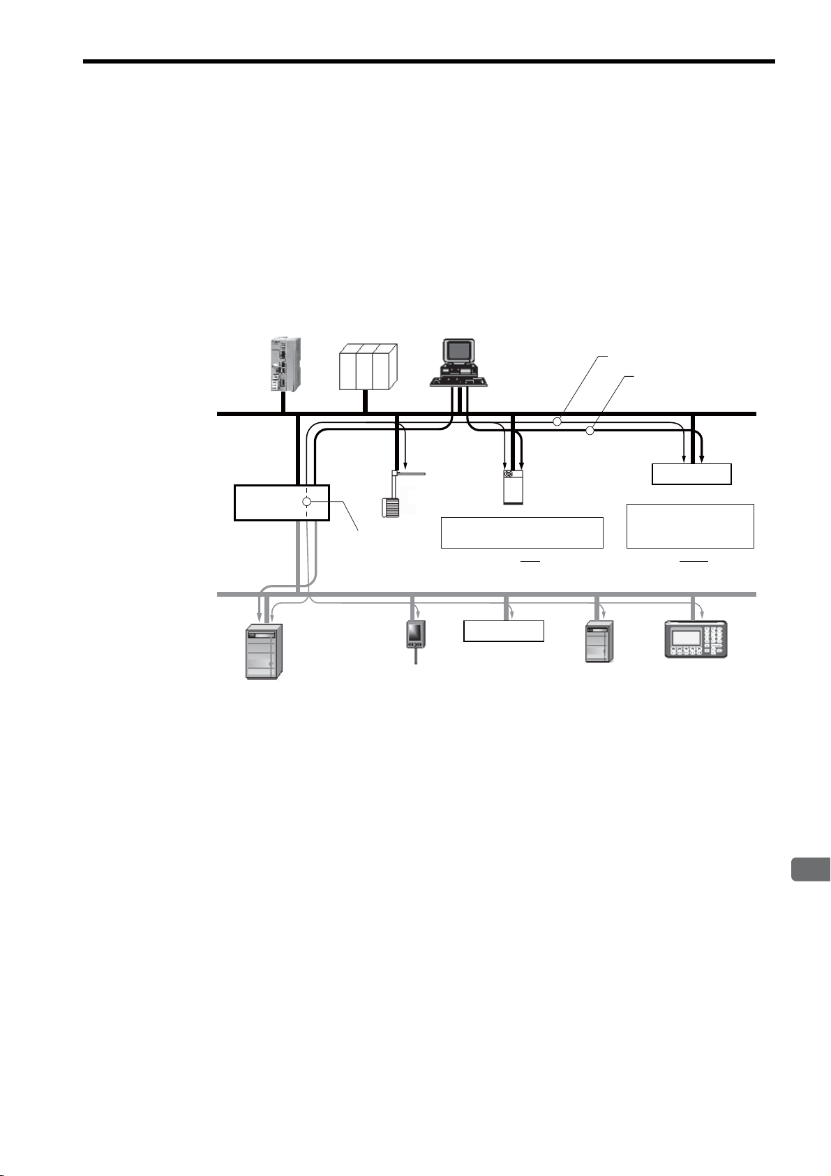
EtherNet/IP is a standard network configured with standard worldwide protocols (Ethernet, TCP/IP, and CIP), it has the
following features since it uses standard protocols.
• Can manage and integrate entire production systems, from field devices to the internet.
• Can control, set, diagnose the device and collect data on the same Ethernet.
• Can use a previously installed Ethernet for the information system.
The following figure illustrates how a system that connects EtherNet/IP devices and DeviceNet using EtherNet/IP may
be arrayed.
1.2 EtherNet/IP Features
Fig. 1.3 Example of EtherNet/IP (Includes DeviceNet) System Configuration
1-3
Page 16

1.3 EtherNet/IP (CIP) Communication Types
1.3.1 Explicit Message Communication
1.3 EtherNet/IP (CIP) Communication Types
There are two kinds of CIP communication: Explicit message communication and I/O communication.
1.3.1 Explicit Message Communication
Explicit messages are used in general message communication between the client and the server (peer-to-peer communication).
• Two types of message communication is available, namely, connected message communication and unconnected
message communication.
• An explicit message contains the communication destination object information and the request details.
Major Applications
Program uploading/downloading, device setting, data collection, diagnosing, etc.
1.3.2 I/O Communication
I/O communication is used for time-critical control data communication.
• Efficient communication is possible since only data is sent/received in I/O communication.
• The meaning of the data is pre-defined for each connection (communication target application object).
Major Applications
Transmission of control data for individual devices, etc.
1-4
Page 17

2
263IF-01 Module
2
263IF-01 Module
This chapter describes the external appearance and specifications of the 263IF-01 Module.
2.1 Features - - - - - - - - - - - - - - - - - - - - - - - - - - - - - - - - - - - - - - - - - - - - - - -2-2
2.1.1 I/O Communication - - - - - - - - - - - - - - - - - - - - - - - - - - - - - - - - - - - - - - - - - - - - - - - - 2-2
2.1.2 Explicit Message Communication - - - - - - - - - - - - - - - - - - - - - - - - - - - - - - - - - - - - - - 2-3
2.1.3 Engineering Communication - - - - - - - - - - - - - - - - - - - - - - - - - - - - - - - - - - - - - - - - - - 2-4
2.2 Specifications - - - - - - - - - - - - - - - - - - - - - - - - - - - - - - - - - - - - - - - - - - - -2-5
2.2.1 Hardware Specifications - - - - - - - - - - - - - - - - - - - - - - - - - - - - - - - - - - - - - - - - - - - - - 2-5
2.2.2 Transmission Specifications - - - - - - - - - - - - - - - - - - - - - - - - - - - - - - - - - - - - - - - - - - 2-6
2.2.3 Software Configuration - - - - - - - - - - - - - - - - - - - - - - - - - - - - - - - - - - - - - - - - - - - - - - 2-8
2.2.4 Operating Environment Specifications - - - - - - - - - - - - - - - - - - - - - - - - - - - - - - - - - - - 2-9
2.3 Overview - - - - - - - - - - - - - - - - - - - - - - - - - - - - - - - - - - - - - - - - - - - - - -2-10
2.3.1 Appearance and Connectors - - - - - - - - - - - - - - - - - - - - - - - - - - - - - - - - - - - - - - - - 2-10
2.3.2 Status Indicators (LEDs) - - - - - - - - - - - - - - - - - - - - - - - - - - - - - - - - - - - - - - - - - - - - 2-10
2.3.3 Communication Status Indicators (LEDs) (Contained in the Ethernet Connector) - - - - 2-11
2.3.4 Switch Settings - - - - - - - - - - - - - - - - - - - - - - - - - - - - - - - - - - - - - - - - - - - - - - - - - - 2-11
2.4 Connection Specifications - - - - - - - - - - - - - - - - - - - - - - - - - - - - - - - - - - 2-12
2.4.1 Connector Specifications - - - - - - - - - - - - - - - - - - - - - - - - - - - - - - - - - - - - - - - - - - - 2-12
2.4.2 Cable Specifications - - - - - - - - - - - - - - - - - - - - - - - - - - - - - - - - - - - - - - - - - - - - - - 2-12
2-1
Page 18

2.1 Features
MP2300
263IF-01
MP2300
263IF-01
Controller, I/O
Adaptor 1 Adaptor 2 Scanner 1
Scanner/Adaptor
Various devices
compatible
with EtherNet/IP
I/O data I/O data
I/O data
Switch
2.1.1 I/O Communication
2.1 Features
A 263IF-01 Module can perform I/O communication, explicit message communication and engineering communication.
2.1.1 I/O Communication
In I/O communication (Class 1), communication of time-critical control data is possible. This type of communication is
mainly used between scanners and adaptors in a 1:1 or 1:N configuration.
I/O communication using the 263IF-01 Module provides both the scanner and adaptor functions and supports a maximum of 64 connected devices (scanner devices and adapter devices). The scanner and adaptor functions operate simultaneously.
The following figure illustrates communication between scanners and adaptors.
The communication trigger for an I/O communication is as follows.
Type Scanner/Adaptor Remarks
Cyclic
Scanner, adaptor Sends the data at specified intervals (at each timeup).
2-2
Page 19

2
263IF-01 Module
2.1.2 Explicit Message Communication
In explicit message communication, general message communication is possible.
In explicit message communication using the 263IF-01 Module, the Module provides both the client (UCMM) and
server (Class 3, UCMM) functions, and is mainly used in communication between the client and server (maximum
number of connected devices = 64) in 1:1 (peer-to-peer) configuration.
The following figure illustrates a layout for communication between clients and a server.
Scanner/Adaptor
MP2300
2.1 Features
2.1.2 Explicit Message Communication
263IF-01
Switch
Command
Response
Command
Response
MP2300
263IF-01
Various devices
compatible
with EtherNet/IP
Client 1 Client 2
The following table shows the types of message communication and their communication triggers.
Communication Type Remarks
Performs message communication after establishing a CIP
connection.
Server: Supported
Client: Not supported
Performs message communication without establishing a CIP
connection.
Sends a message upon occurrence of an event.
(Uses a message send function.)
Message
Communication
Communication Trigger
Connected
message communication
Unconnected (UCMM)
message communication
Driven by application object
(event)
2-3
Page 20
2.1 Features
2.1.3 Engineering Communication
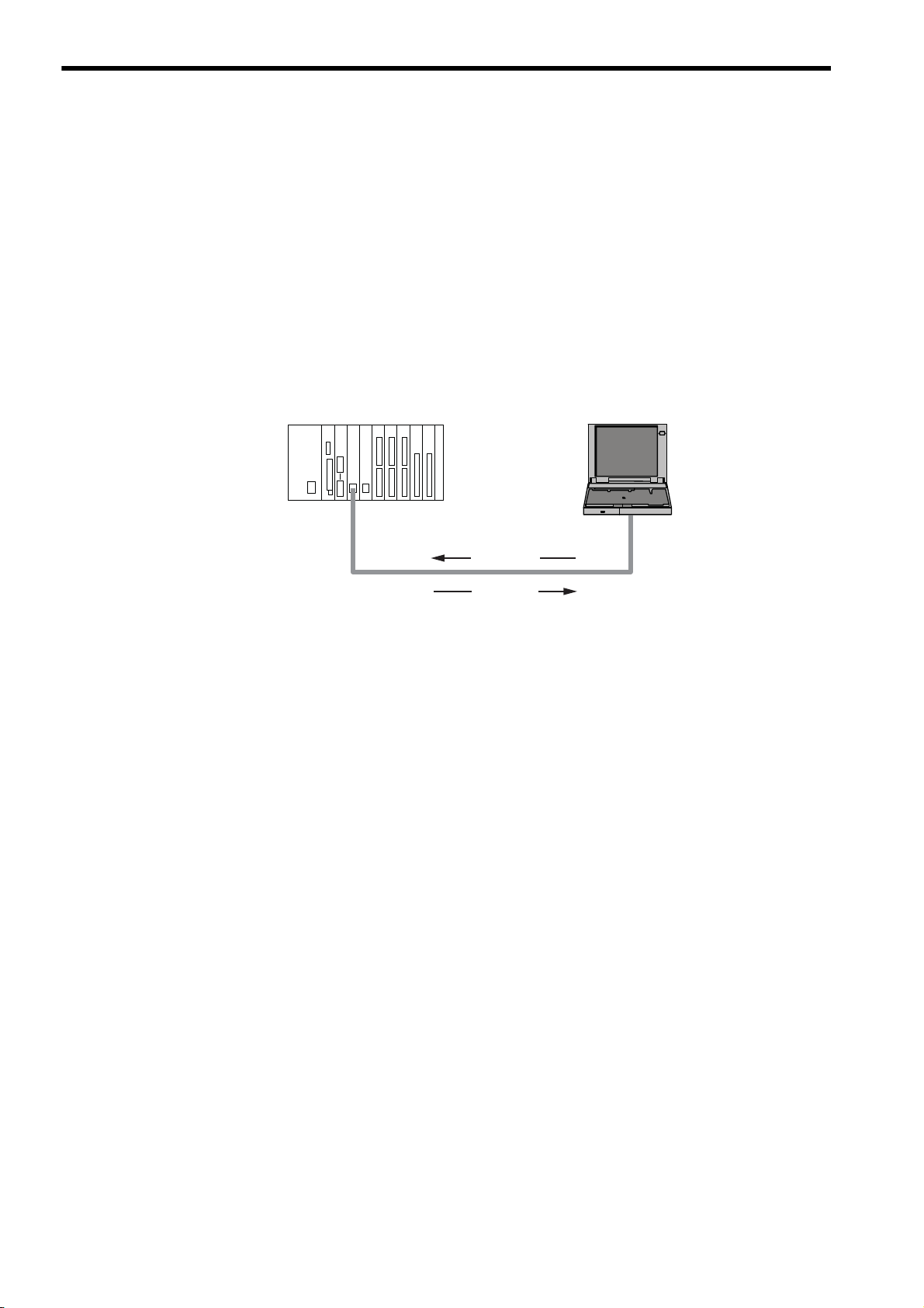
2.1.3 Engineering Communication
By connecting the 263IF-01 Module to the Programming Device MPE720, ladder programming and monitoring are
possible through engineering communication.
The self configuration function of the MP2000-series Machine Controller enables an Ethernet connection between the
personal computer where MPE720 is installed and the 263IF-01 Module, without requiring settings for connections at
the 263IF-01 Module.
The Communication Manager setting on the personal computer and connection setting on the MPE720 are neces-
sary. For details, refer to 3.3.2 Setting the Communication Manager on page 3-10, 3.5.1 Starting MPE720 Ver. 6 and
Setting Communication Parameters on page 3-15 and 3.5.2 Starting MPE720 Ver. 5.xx and Setting Network Parameters on page 3-16.
The following figure illustrates a layout for connection with the MPE720.
CPU-02
MP2200
263IF-01 262IF-01
LIO-04SVB-01
LIO-04 LIO-04 LIO-01 LIO-01
Personal computerMP2000-series Machine Controller
Command
Response
MPE720
2-4
Page 21

2
263IF-01 Module
2.2 Specifications
This section provides specifications for the 263IF-01 Module.
2.2.1 Hardware Specifications
Item Specification
Name
Model
Communication Port
Indicators
Switch
Dimensions (mm)
Mass
263IF-01
JAPMC-CM2304-E
EtherNet/IP: 1 port
Module status indicators LED
MS (red/green)
TX (green)
EtherNet/IP status indicator LED
LINK (yellow)
100M (green/orange)
INIT
TEST
125 × 95 mm (H × D)
80 g
2.2 Specifications
2.2.1 Hardware Specifications
NS (red/green)
IP (green)
RX (green)
2-5
Page 22

2.2 Specifications
2.2.2 Transmission Specifications
2.2.2 Transmission Specifications
Item Specifications
Interface RJ-45 connector
Compliance Standard
Media Access Mode CSMA/CD
Communication Mode Full duplex/half duplex
Modulation Method Baseband
Topology Bus
Communication Protocol TCP/UDP/IP/ICMP/IGMP
Baud Rate
Ethernet
Transmission
Specifications
EtherNet/IP
Specifications
I/O
Communication
Specifications
Maximum Number of
Cascade Connections
Transmission Path Length
(Full length at repeater
usage)
Transmission Media
Maximum Segment Length 100 m (distance between hub and node at UTP usage)
Link Function
IP Address
Port Number
Communication Protocol
Device Type
Supported Objects
Product Level
Maximum Number of
Connectable I/O Devices
Max. Number of I/O Bytes
Communication Mode
Communication Mode at
Startup
Communication Trigger
100BASE-TX 10BASE-T
IEEE802.3u IEEE802.3i
100 Mbps 10 Mbps
2 levels 4 levels
*1
100 m (500 m max.
Twisted-pair cable (UTP)
Category 5 or 5e
Twisted-pair cable (STP)
Category 5 or 5e (100 Ω)
) 100 m (205 m max.*1)
Twisted-pair cable (UTP)
Category 3, 4, 5, or 5e
Twisted-pair cable (STP)
Category 3, 4, 5, or 5e (100 Ω)
Support for auto-negotiation
(not possible to fix transmission and communication modes)
Support for Auto MDI/MDI-X
To be set by Programming Device (DHCP and BOOTP are not supported.)
I/O communication:
The system uses one port at 2222 (0x08AE).
*2
Explicit message communication:
The system uses one port at 44818 (0xAF12).
*2
Conforms to EtherNet/IP (CIP)
Communication adaptor
Mandatory objects
• Identity
• Message Router
• Ethernet Link
*4
• TCP/IP Interface
• Connection Manager
Optional objects
• Assembly
• UCMM (Unconnected Message Manager; Non-object)
•Port
Level 4
I/O communication: Scanner and adaptor
Explicit message communication: Client and server
*3
64 units
(Does not include the devices used for explicit message communication)
*3
Inputs/outputs: 8192 bytes each
per system (Total number of bytes of input/
output data exchanged among all connected devices)
*2
Inputs/outputs: 500 bytes each
per device
Scanner, adaptor
Simultaneous start of scanners and adaptors
Cyclic
2-6
Page 23

2.2.2 Transmission Specifications
2
263IF-01 Module
Item Specifications
Max. Number of
Connectable Devices for
Explicit Message
Communication
Number of Message
Channels
Explicit
Message
Specifications
∗ 1. The maximum transmission path length when a switching hub is used.
Use a switching hub for the Ethernet (available at any electronics shop)
(A product manufactured by the Japan Electrical Manufacturers' Association is recommended.)
∗ 2. EtherNet/IP (CIP) specifications
∗ 3. Restrictions due to MP2000-series Machine Controller specifications
∗ 4. The following table describes objects in detail.
Max. Number of Message
Bytes
Function for Execution
Communication Mode
Connection Type
Communication Trigger
*3
64 units
(Number of devices that can communicate simultaneously: 10)
10
504 bytes
MSG-SND Function
Client and server
Unconnected type (UCMM)
Application object driven
*2
When the Module functions as a server, connected type (class 3) is
also supported.
2.2 Specifications
Object Name Class ID
Identity
Message Router
Assembly
Connection Manager
Port
Ethernet Link
TCP/IP Interface
Optional/
Mandatory
*2
(See
0x01 Mandatory
0x02 Mandatory
0x04 Optional
0x06
0xF4 Optional
0xF5
0xF6
Mandatory
(conditional)
Mandatory
(conditional)
Mandatory
(conditional)
Description
above)
• Retains the identification information of a device. The
device identification information can be obtained by
reading the attributes of an Identity object.
• Supports device reset processing to be activated
through the network.
<Attributes>
Vendor ID, device type, product code, revision, status,
product serial number, product name, state, etc.
• Transfers the received explicit request to the specified
object.
• To be specified in the connection path used when
establishing the connection for explicit message
communication.
Provides the access map for accessing attributes or I/O
data in a device.
• Issues and receives the Forward_Open service and
creates the CIP connection.
• Retains the CIP connection information and secures the
necessary internal resources.
• Retains the information of the connection ports that can
be used in the CIP network.
• Used when searching for the CIP routing information.
Provides the EtherNet/IP interface.
Provides the EtherNet/IP interface.
2-7
Page 24

2.2 Specifications
Application layer
Presentation layer
Session layer
Transport layer
Network layer
Scanner/adaptor
function
EtherNet/IP
communication
protocol
Engineering
tool interface
Data link layer
Host interface
CPU Module
Physical layer
TCP/UDP
ARP/IP/ICMP/IGMP
Ethernet
10BASE-T/100BASE-TX
2.2.3 Software Configuration
2.2.3 Software Configuration
The following figure illustrates the software configuration that provides the 263IF-01 Module functions.
The following table provides the details of the individual protocols.
Protocol Details
TCP (Transmission Control Protocol)
UDP (User Datagram Protocol)
IP (Internet Protocol)
ICPM (Internet Control Message Protocol)
IGMP (Internet Group Management Protocol)
ARP (Address Resolution Protocol)
Connection type transport layer protocol
Connection type transport layer protocol
Protocol that establishes the communication path between computers
Protocol that handles error control in the IP protocol
Protocol used for IP multicast
Converts an IP address into a MAC address.
2-8
Page 25

2
263IF-01 Module
2.2.4 Operating Environment Specifications
Item Specifications
Ambient
Environmental
Conditions
Mechanical
Operating
Conditions
Operating
Temperature
Ambient
Storage
Temperature
Ambient
Operating
Humidity
Ambient
Storage
Humidity
Pollution Level Pollution level: 2 (conforming to JIS B3502)
Corrosion
Resistance
Operating
Altitude
Vibration
Resistance
Shock
Resistance
0 to +55 °C
−25 to +85°C
30% to 95% RH (with no condensation)
5% to 95% RH (with no condensation)
There must be no combustible or corrosive gas.
2,000 m above sea level or lower
Conforming to JIS B3502
(1) Frequency: 16.7 Hz Vibration strength: 14.7 m/s
(2) Frequency: 10 to 57 Hz Vibration strength: 0.075 mm of single-amplitude
(3) Frequency: 57 to 150 Hz Vibration strength: 9.8 m/s
Conforming to JIS B3502
Peak acceleration of 147 m/s
directions
2.2 Specifications
2.2.4 Operating Environment Specifications
2
2
of fixed acceleration
2
(15G) twice for 11 ms each in the X, Y, and Z
Electrical
Operating
Conditions
Installation
Requirements
Conforming to EN 61000-6-2, EN 55011 (Group 1, Class A)
Noise
Resistance
Ground Ground to 100 Ω max.
Cooling Method Natural cooling
Power supply noise (FT noise): ±2 kV min., for one minute
Radiation noise (FT noise): ±1 kV min., for one minute
Ground noise (impulse noise): ±1 kV min., for ten minutes
Electrostatic noise (contact discharge method): ±6 kV min., ten times
2-9
Page 26
2.3 Overview
EtherNet/IP connector
100Base-TX/10Base-T
Status indicators
(LEDs)
Switches
263IF-01
NS
IP
RX
MS
TX
TEST
INIT
ONOFF
LINK
100M
EtherNet/IP
Communication status
indicator (LED)
(contained in the connector)
(25 mm)
NO
NS
IP
RX
MS
TX
2.3.1 Appearance and Connectors
2.3 Overview
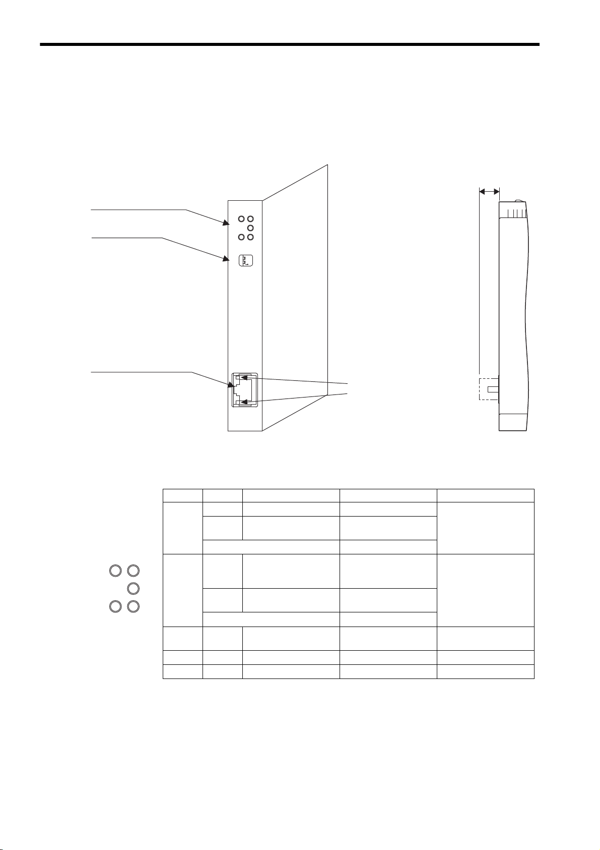
2.3.1 Appearance and Connectors
The following illustration shows the appearance of the 263IF-01 Module and provides the external dimensions of the
connector.
2.3.2 Status Indicators (LEDs)
The following table shows the status of the 263IF-01 Module indicated by the LED indicators.
Indicator Color Meaning When Lit
MS
Green
Red
Operating normally Device not set
Module error
(Unrecoverable)
Alternately flashing green/red During self-testing
NS
IP Green
TX Green
RX Green
Green
Red
Operating normally
Error
(Duplicated IP address)
Alternately flashing green/red During self-testing
IP address acquisition
completed
Sending data
Receiving data
For details on the Module status indicated by the LED indicators, refer to 6.1 Status Indication by LED Indicators on
page 6-2.
Meaning When Flashing
Module error
(Recoverable)
Connection being established, or no I/O allocations
Communication error
(Timeout)
–
–
–
Meaning When Not Lit
Module power supply
disconnected/Startup
failure
Communication power
supply disconnected/No
IP address
IP address acquisition not
completed
Not sending data
Not receiving data
2-10
Page 27

2.3.3 Communication Status Indicators (LEDs) (Contained in the Ethernet Connector)
2
263IF-01 Module
TEST
INIT
ONOFF
2.3.3 Communication Status Indicators (LEDs)
(Contained in the Ethernet Connector)
The indicators (LEDs) contained in the EtherNet/IP connector indicate the status of EtherNet/IP communication.
Indicator Color Meaning When Lit Meaning When Not Lit
LINK Yel l ow
EtherNet/IP link established EtherNet/IP link not established
2.3 Overview
100M Green/orange
2.3.4 Switch Settings
The following table shows the 263IF-01 Module switch settings.
(Switch No.)
Always leave the unused switches (Nos. 3 and 4), located behind the faceplate, OFF.
Label
INIT
(2)
TEST
(1)
Green: 100 Mbps
(Orange: 1 Gbps)
Name Status Function
Transmission Parameters Startup Selection
(For Programming Device)
Operating Mode Selection
10 Mbps or not connected
ON
Initial startup
OFF
Normal operation mode
ON
Reserved by the system.
OFF
Always set to OFF.
Factory
Setting
OFF
OFF
2-11
Page 28
2.4 Connection Specifications
LINK
100M
EtherNet/IP
LINK
100M
EtherNet/IP
2.4.1 Connector Specifications
2.4 Connection Specifications
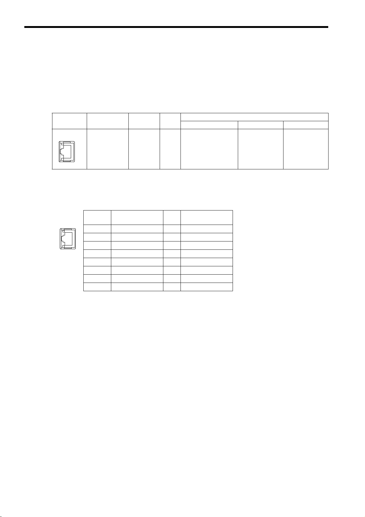
2.4.1 Connector Specifications
This section explains the connector specifications for the 263IF-01 Module.
( 1 ) Connector Specifications
Connector
Shape
Name
EtherNet/IP EtherNet/IP 8
Connector
Name
No. of
Pins
Module Cable Manufacturer
JOG-0001NL
(LED/Pulse transformer
built-in modular jack)
Connector Model
–
( 2 ) Connector Pin Arrangement
The connector is used to connect the 263IF-01 Module to the devices in the EtherNet/IP network via an EtherNet/IP
connection.
Pin
Number
1
2
3
4
5
6
7
8
Signal Name I/O Description
TXD+ O
TXD- O
RXD+ I
–––
–––
RXD- I
–––
–––
Send data +side
Send data -side
Receive data +side
Receive data -side
Pulse Engineering
2.4.2 Cable Specifications
Yaskawa does not provide EtherNet/IP cables. Obtain commercially available category 5 cross or straight cables.
The AUTO MDI/MDI-X function of the 263IF-01 Module automatically distinguishes between cross and straight
cables.
2-12
Page 29

3
Mounting and Starting the Module
3
Mounting and Starting the Module
This chapter describes how to connect the 263IF-01 Module and start the system, focusing on
mounting the 263IF-01 Module, communication process setting, and self-configuration.
3.1 Applicable Machine Controllers and Supported Versions - - - - - - - - - - - - -3-2
3.1.1 Applicable Machine Controllers - - - - - - - - - - - - - - - - - - - - - - - - - - - - - - - - - - - - - - - - 3-2
3.1.2 Supported CPU and MPE720 Versions - - - - - - - - - - - - - - - - - - - - - - - - - - - - - - - - - - 3-2
3.2 Mounting and Removing a Module on the Machine Controller - - - - - - - - - -3-3
3.2.1 Mounting a 263IF-01 Module - - - - - - - - - - - - - - - - - - - - - - - - - - - - - - - - - - - - - - - - - 3-3
3.2.2 Removing a 263IF-01 Module - - - - - - - - - - - - - - - - - - - - - - - - - - - - - - - - - - - - - - - - - 3-6
3.3 Setting the Communication Manager - - - - - - - - - - - - - - - - - - - - - - - - - - - 3-8
3.3.1 Preparation of the Personal Computer - - - - - - - - - - - - - - - - - - - - - - - - - - - - - - - - - - - 3-8
3.3.2 Setting the Communication Manager - - - - - - - - - - - - - - - - - - - - - - - - - - - - - - - - - - - 3-10
3.4 Self-configuration - - - - - - - - - - - - - - - - - - - - - - - - - - - - - - - - - - - - - - - - 3-14
3.4.1 Executing Self-configuration - - - - - - - - - - - - - - - - - - - - - - - - - - - - - - - - - - - - - - - - - 3-14
3.5 Starting the MPE720, and Setting Communication or Network Parameters 3-15
3.5.1 Starting MPE720 Ver. 6 and Setting Communication Parameters - - - - - - - - - - - - - - - 3-15
3.5.2 Starting MPE720 Ver. 5.xx and Setting Network Parameters - - - - - - - - - - - - - - - - - - 3-16
3-1
Page 30

3.1 Applicable Machine Controllers and Supported Versions
3.1.1 Applicable Machine Controllers
3.1 Applicable Machine Controllers and Supported Versions
3.1.1 Applicable Machine Controllers
The MP2000-series Machine Controllers to which the 263IF-01 Modules can be mounted are listed in the following
table.
Max. No. of
Name Model
Base Unit with 100/
MP
2200
MP2300 JEPMC-MP2300 2 modules
200-VAC input
Base Unit with
24-VDC input
∗1
∗1
JEPMC-BU2200
JEPMC-BU2210
Connectable
Modules
8 modules
Remarks
The maximum number of connectable Modules
is the total for the maximum expansion to four
∗2
Racks.
–
MP2310 JEPMC-MP2310-E 3 modules
MP2300S JEPMC-MP2300S-E 1 module
MP2100M
MP2500MD
* 1. One of the following CPU Module is required.
Name Model Remarks
CPU-01
CPU-02
CPU-03
CPU-04
∗ 2. An EXIOIF Inter-Rack Connection Module (model: JAPMC-EX2200) is required to add Expansion Racks.
The 263IF-01 Modules cannot be mounted on the following MP2000-series Machine Controllers: MP2100, MP2400,
MP2500, MP2500M, and MP2500D.
JAPMC-MC2140 8 modules
JAPMC-MC2540-D 8 modules
JAPMC-CP2200 –
JAPMC-CP2210 With one slot for CF card and one USB port
JAPMC-CP2220-E With one slot for CF card and one Ethernet port
JAPMC-CP2230-E With one Ethernet port
3.1.2 Supported CPU and MPE720 Versions
–
–
The 263IF-01 Modules can be mounted on the
Expansion Racks (which use the MP2200 Base
Unit) connected to an Expansion Interface
Board (MP2100MEX, model: JAPMCEX2100) mounted on the Machine Controller.
The maximum number of connectable Modules
is the total for the maximum expansion to three
∗2
Racks.
3-2
The following table lists the CPU and MPE720 versions that can be used with the 263IF-01 Module.
Machine Controller
CPU-01 Ver. 2.64 or later Ver. 5.42 or later Ver. 6.08 or later
MP2200
MP2300 Ver. 2.64 or later Ver. 5.42 or later Ver. 6.08 or later
MP2310 Ver. 2.64 or later Ver. 5.42 or later Ver. 6.08 or later
MP2300S Ver. 2.64 or later Ver. 5.42 or later Ver. 6.08 or later
MP2100M Ver. 2.64 or later Ver. 5.42 or later Ver. 6.08 or later
MP2500MD Ver. 2.64 or later Ver. 5.42 or later Ver. 6.08 or later
CPU-02 Ver. 2.64 or later Ver. 5.42 or later Ver. 6.08 or later
CPU-03 Ver. 2.70 or later Ver. 5.50 or later Ver. 6.20 or later
CPU-04 Ver. 2.72 or later Ver. 5.52 or later Ver. 6.22 or later
CPU MPE720 (CPMC-720)
Supported Versions
MPE720 Ver. 6 (CPMC-770)
Page 31

3.2 Mounting and Removing a Module on the Machine Controller
3
Mounting and Starting the Module
<MP2200/MP2300/MP2200 Base Unit>
Insert a hard thin metal object, such as a coin, into
the notch on the side of the battery cover and open
the cover forward to remove the battery cover.
<MP2310/MP2300S>
Insert a finger in the lug on the lower part of the battery cover as shown in the figure and remove the
battery cover.
3.2.1 Mounting a 263IF-01 Module
3.2 Mounting and Removing a Module on the Machine Controller
This section explains the procedure for mounting and removing a 263IF-01 Module.
3.2.1 Mounting a 263IF-01 Module
Use the following procedure to mount a 263IF-01 Module.
Before replacing a 263IF-01 Module, remove the 263IF-01 Module that needs to be replaced referring to 3.2.2
Removing a 263IF-01 Module on page 3-6.
( 1 ) Preparation
1. Backup the Programs.
Save the programs written to the Machine Controller in the personal computer using MPE720.
MPE720 Ver. 5.xx: Right-click the PLC folder and then select Transfer - All Files - From Controller to
MPE720.
MPE720 Ver. 6.xx: Open the project file and then select Online - Transfer - Read from Controller.
2. Save in the Flash Memory.
Save the programs written to the Machine Controller in the flash memory using the MPE720.
MPE720 Ver. 5.xx: Right-click the PLC folder and then select Transfer - Other - Save to Flash.
MPE720 Ver. 6.xx: Open the project file and then select Online - Transfer - Save to Flash.
3. Remove the Machine Controller and Expansion Rack.
Turn OFF the power supply and remove all the cables connected to the Machine Controller or Expansion Rack
(MP2200 Base Unit). Then, remove the Machine Controller and Expansion Rack from the panel or rack, and
place them where there is sufficient space, such as on a work table.
( 2 ) Removing the Option Cover
If an Option Cover is attached to the slot into which the 263IF-01 Module is to be mounted, remove it using the following procedure.
1. Remove the Battery Cover.
3-3
Page 32

3.2 Mounting and Removing a Module on the Machine Controller
Guide
rail
3.2.1 Mounting a 263IF-01 Module
2. Remove the Option Cover.
Hold the battery cover with the front facing forward, insert the protrusion on the battery cover into the notch at
the top of the Option Cover, and release the hook on the Option Cover.
Release the hook on the bottom in the same way and remove the Option Cover.
( 3 ) Mounting Procedures
1. Insert the 263IF-01 Module.
Grip the top and bottom of the 263IF-01 Module, align the Module with the left side of the guide rail inside the
option slot, and push the Module straight in.
If the Module is not inserted along the guide rail correctly, the frame ground bar on the bottom of the slot may
get damaged.
2. Connect to the Mounting Base Connector.
After inserting the Module completely, press the Module firmly until it connects securely with the Mounting
Base connector. If the Module is connected securely, the front of the Module should approximately align with the
hooks.
3-4
3. Mount the Option Panel.
Insert the bottom hook into the hole on the bottom of the operation panel and then securely insert the top hook
into the hole.
This completes the mounting procedure.
Page 33

3
Mounting and Starting the Module
( 4 ) After Mounting the Module
1. Connect to the Hub.
Connect the 263IF-01 Module and the hub using the Ethernet cable.
Refer to 2.4.2 Cable Specifications on page 2-12 for cables that can be used.
2. Create Module Configuration Definitions.
a) After Mounting New Modules
Execute self-configuration for each slot in which a 263IF-01 Module has been newly mounted.
Refer to 3.4 Self-configuration on page 3-14 for more information.
b) After Replacing Modules
Turn OFF the CNFG and INIT DIP switches on the Machine Controller and turn ON the power supply.
After turning ON the power, modify the module configuration as required.
Refer to 4.1.1 Displaying the Module Configuration Window on page 4-2 for information on the Module
configuration definitions.
3.2 Mounting and Removing a Module on the Machine Controller
3.2.1 Mounting a 263IF-01 Module
3-5
Page 34

3.2 Mounting and Removing a Module on the Machine Controller
<MP2200/MP2300/MP2200 Base Unit>
Insert a hard thin metal object, such as a coin, into
the notch on the side of the battery cover and open
the cover forward to remove the battery cover.
<MP2310/MP2300S>
Insert a finger in the lug on the lower part of the battery cover as shown in the figure and remove the
battery cover.
3.2.2 Removing a 263IF-01 Module
3.2.2 Removing a 263IF-01 Module
Use the following procedure to remove a 263IF-01 Module.
( 1 ) Preparation
1. Backup the Programs.
Save the programs written to the Machine Controller in the personal computer using MPE720.
MPE720 Ver. 5.xx: Right-click the PLC folder and then select Transfer - All Files - From Controller to
MPE720.
MPE720 Ver. 6.xx: Open the project file and then select Online - Transfer - Read from Controller.
2. Remove the Machine Controller and Expansion Rack.
Turn OFF the power supply and remove the cables connected to the Machine Controller or Expansion Rack.
Then, remove the Machine Controller and Expansion Rack from the panel or rack and place them where there is
sufficient space, such as on a work table.
( 2 ) Removing Procedures
1. Remove the Battery Cover.
2. Remove the Option Panel.
Hold the battery cover with the front facing forward, insert the protrusion on the battery cover into the notch at
the top of the Module's option panel, and release the hook on the option panel.
3-6
Release the hook on the bottom in the same way and remove the option panel.
Page 35

3.2 Mounting and Removing a Module on the Machine Controller
3
Mounting and Starting the Module
Round
projection
Notch
Fulcrum
3.2.2 Removing a 263IF-01 Module
3. Remove the 263IF-01 Module from the Mounting Base.
Pull the top of the option panel to remove it. A notch can be seen in the 263IF-01 Module from the gap in the
panel. Insert the round projection on the battery cover (see the following figure) into the gap in the panel so that
it engages the notch in the Module.
Hold the battery cover as shown in the following figure and rotate it toward the rear, using the round projection as
a fulcrum to disconnect the Module from the Mounting Base connector. The Module will come out toward the
front.
4. Pull Out the 263IF-01 Module.
Hold onto the top and bottom of the Module with your fingers and pull the Module straight out. Be sure to hold
onto the edges of the Module. Do not touch the components mounted to the Module.
Place the Module that you removed into the bag that it was delivered in and store it.
Always attach an Option Cover (JEPMC-OP2300) to any unused slot.
3-7
Page 36

3.3 Setting the Communication Manager
3.3.1 Preparation of the Personal Computer
3.3 Setting the Communication Manager
This section describes the software called the Communication Manager that is used to set the communication method
for engineering communication between the personal computer running the MPE720 and the MP2000-series Machine
Controller.
When a 263IF-01 Module is used for communication between the MPE720 (personal computer) and a Machine Controller, set the communication method with the Communication Manager in accordance with the Module to be used.
Set the communication conditions with the Communication Manager after the MPE720 Programming Device has been
installed. Once they have been set, you do not need to set them for subsequent start-ups, except when other conditions
are to be added.
3.3.1 Preparation of the Personal Computer
Before starting EtherNet/IP connection, a general-purpose Ethernet board or PCMCIA Ethernet card must be installed
on the personal computer. Before making the settings, the IP address of the personal computer must be set.
( 1 ) Mounting an Ethernet Card
Mount a general-purpose Ethernet board or PCMCIA Ethernet card on the specified connector of the personal computer. Also, install the driver provided with the Ethernet card.
( 2 ) Setting the IP Address
Before making the settings for EtherNet/IP connections, the IP address of the personal computer must be set. Set the IP
address by the procedure below:
Make the following settings with the LAN cable connected.
1. Click the Windows Start button and select Settings - Control Panel - Internet Options.
The Internet Properties dialog box will be displayed.
2. Click the Connections tab to display the tab page. Click the LAN Settings... button.
3-8
The Local Area Network (LAN) Settings dialog box will be displayed.
Page 37

3.3 Setting the Communication Manager
3
Mounting and Starting the Module
3.3.1 Preparation of the Personal Computer
3. Check that the Automatically detect settings check box is cleared, and click the OK button to close
the dialog box.
4. For a computer running Windows 2000, click the Windows Start button and select Settings - Control
Panel - Network and Dial-up Connections.
For a computer running Windows XP, click the Windows Start button and select Settings - Control
Panel - Network Connections.
On a computer running Windows 2000, the Network and Dial-up Connections window will be displayed. On a
computer running Windows XP, the Network Connections window will be displayed.
5. On a computer running Windows 2000, double-click the Local Area Connection icon.
On a computer running Windows XP, click Local Area Connection and click Change settings of this
connection in the Network Tasks menu.
Windows 2000
The Local Area Connection Properties dialog box will be displayed.
Windows XP
6. Select Internet Protocol (TCP/IP) and click the Properties button.
The Internet Protocol (TCP/IP) Properties dialog box will be displayed.
3-9
Page 38

3.3 Setting the Communication Manager
Double-click
Communication Manager icon
3.3.2 Setting the Communication Manager
7. Select Use the following IP address and enter “192.168.1.2” for IP address and “255.255.255.0” for
Subnet mask. Then click the OK button to close the dialog box.
3.3.2 Setting the Communication Manager
( 1 ) Opening the Communication Manager
1. Double-click the Communication Manager icon in the YE_Applications folder on the desktop to start
the Communication Manager. Or, select All Programs - YE-Applications - Communication Man-
ager under the Windows Start button.
The Communication Manager icon will be displayed in the task tray at the right bottom of the window.
2. Double-click the Communication Manager icon in the task tray.
The Communication Manager window will open.
Logical ports for up to 16 channels can be set in the Communication Manager window.
3-10
Page 39

3.3 Setting the Communication Manager
3
Mounting and Starting the Module
3.3.2 Setting the Communication Manager
( 2 ) Setting the Ethernet Communication Port
1. In the Communication Manager window, double-click the number in the Logical PT column of a line
which has not been set (In the following example, Line 2 and subsequent lines have not been set.) to
view the Logical Port Setting dialog box.
2. Select Ethernet or CP-218 under Port Kind in the Logical Port Setting dialog box and click the
Detail button.
Ethernet and CP-218 require the same communication specifications. Either can be set for EtherNet/IP
(10BASE-T) communication.
The CP-218 Port Setting dialog box will be displayed.
3. Enter the IP address of computer and click OFF for Default. Leave the other items on their default set-
tings. Click the OK button to close the dialog box.
4. Click the OK button in the Logical Port Setting dialog box. The display will return to the Communica-
tion Manager window. Confirm that CP-218 (Ethernet connection) is allocated to the Logical Port num-
ber that you selected.
3-11
Page 40

3.3 Setting the Communication Manager
3.3.2 Setting the Communication Manager
5. Save the settings and restart the Communication Manager.
Refer to 3.3.2 ( 4 ) Saving the Communication Port Settings and Restarting the Communication Manager on
page 3-13 for the procedure.
( 3 ) Setting the Ethernet (LP) Communication Port
These settings are optimum for performing engineering via the Ethernet communication port of the 263IF-01
Module.
Since the engineering message size is expanded at the Ethernet (LP) communication port compared with the conventional Ethernet communication port (CP218/Ethernet), high-speed engineering communication is possible.
1. In the Communication Manager window, double-click the number in the Logical PT column of a line
which has not been set ([3] and greater in the figure below) to display the Logical Port Setting dialog
box.
2. Select Ethernet (LP) under Port Kind in the Logical Port Setting dialog box and click the Detail but-
ton.
The CP-218/Ethernet (LP) Port Setting dialog box will be displayed.
3. Enter the IP address of the computer in the IP Address (First) box, and confirm that the rest of the set-
tings are as shown here. Then click the OK button.
3-12
The CP-218/Ethernet (LP) Port Setting dialog box is closed and the display will return to the Logical Port
Setting dialog box.
Page 41

3.3 Setting the Communication Manager
3
Mounting and Starting the Module
Double-click
3.3.2 Setting the Communication Manager
4. Click the OK button in the Logical Port Setting dialog box. The display will return to the Communica-
tion Manager window. Confirm that Ethernet (LP) is allocated to the selected Logical Port number.
5. Save the settings and restart the Communication Manager.
Refer to 3.3.2 ( 4 ) Saving the Communication Port Settings and Restarting the Communication Manager on
page 3-13 for the procedure.
( 4 ) Saving the Communication Port Settings and Restarting the Communication Manager
Save the communication port settings, and restart the Communication Manager to validate the settings.
1. Select File - Save. A save confirmation message will be displayed. Click the Yes button to save the
communication port settings.
These settings will be used as the communication port information whenever the Communication Manager is
started.
2. Close the Communication Manager window and restart to validate the settings.
Select File - Exit to close the Communication Manager window. A confirmation message will be displayed. Click the Yes button to close the Communication Manager window.
3. Double-click the Communication Manager icon in the YE_Applications folder to reopen the Com-
munication Manager window.
3-13
Page 42

3.4 Self-configuration
3.4.1 Executing Self-configuration
3.4 Self-configuration
The self-configuration function automatically detects the Option Modules connected to the Machine Controller and
automatically generates the files for the Module configuration definitions and the detailed definition of each Module.
Executing self-configuration will greatly reduce the system startup procedure.
After executing self-configuration, always save data to flash memory so that the results of self-configuration
are saved to the Machine Controller.
3.4.1 Executing Self-configuration
The methods used to execute self-configuration are described below.
( 1 ) Setting the CNFG DIP Switch Pin and Turning the Power ON
(MP2200/MP2300/MP2310/MP2300S)
Self-configuration can be executed by turning ON the CNFG DIP switch pin on the Machine Controller and then turning the power ON. The result will depend on the setting of the INIT DIP switch pin.
CNFG INIT Result
ON ON
ON OFF
• The Module configuration definitions are updated.
• The default values are allocated in the definitions for all of the Modules that are detected.
• The Module configuration definitions are updated.
• The definitions for any Modules for which definitions already exist are not changed.
• The default values are allocated in the definitions for any new Modules that are detected.
The DIP switch is not normally used for the MP2100M/MP2500MD. For these Machine Controllers, execute self-
configuration by following the procedure described in (2) Using the MPE720 (MP2100M/MP2500MD) below.
( 2 ) Using the MPE720 (MP2100M/MP2500MD)
After starting the MPE720, start the Engineering Manager, and then select Order - Self Configure All Modules from
the main menu in the Module Configuration window. Alternatively, select the Module for which self-configuration is
to be executed in the Module Configuration window, and then select Order - Module Self-configuration from the
Main Menu.
Refer to 4.1.1 Displaying the Module Configuration Window on page 4-2 for the procedure to display the Module
Configuration window.
The result depends on the command that is used, as described below.
Command Result
Self-configuration for all
Modules
Module Self-configuration
• The Module configuration definitions are updated.
• The definitions for any Modules for which definitions already exist are not changed.
• The default values are allocated in the definitions for any new Modules that are detected.
• Definitions are allocated only for the selected Module.
• The definitions for any Modules for which definitions already exist are not changed.
• The default values are allocated in the definitions for any new Modules that are detected.
3-14
Page 43

3.5 Starting the MPE720, and Setting Communication or Network Parameters
3
Mounting and Starting the Module
3.5.1 Starting MPE720 Ver. 6 and Setting Communication Parameters
3.5 Starting the MPE720, and Setting Communication or Network
Parameters
This section describes how to start the MPE720, and how to set the communication parameters in the object file
(MPE720 Ver. 6) or the network parameters in the PLC folder (MPE720 Ver. 5.xx).
3.5.1 Starting MPE720 Ver. 6 and Setting Communication Parameters
This section describes how to start MPE720 Ver. 6 and set the communication parameters in the object file.
Disconnect the Machine Controller when setting the parameters.
Create the object file in advance.
1. Select Online - Communications Setting from the Main Menu. Or, select Controller - Communica-
tions Setting (or Project - Communications Setting in the Start window).
The Communications Setting dialog box will be displayed.
2. Select the logical port number to connect to the Machine Controller, and click the Setting button.
Settings for the logical port numbers are made with the Communication Manager. Refer to 3.3 Setting the
Communication Manager on page 3-8 for the Communication Manager setting procedure.
Communication will be set and the dialog box will close.
The Connection and Setting buttons will be disabled while the Machine Controller is connected, preventing
communication settings from being made.
3-15
Page 44

3.5 Starting the MPE720, and Setting Communication or Network Parameters
3.5.2 Starting MPE720 Ver. 5.xx and Setting Network Parameters
3.5.2 Starting MPE720 Ver. 5.xx and Setting Network Parameters
This section describes how to start the MPE720 and set the network parameters in the PLC folder.
Create the PLC folder in advance.
1. Open the YE_Applications folder and double-click the MPE720 icon.
Alternatively, select MPE720 from the Start menu.
The procedure for selecting the network will vary, depending on the operating system.
The MPE720 will start and the File Manager window will be displayed.
2. Open the root, group, and then order folder, right-click the desired PLC folder, and select Properties
from the pop-up menu that is displayed.
3-16
The Controller Configuration dialog box will be displayed.
Page 45

3.5 Starting the MPE720, and Setting Communication or Network Parameters
3
Mounting and Starting the Module
3.5.2 Starting MPE720 Ver. 5.xx and Setting Network Parameters
3. Click the Network tab and select Yes for OnLine.
Fields will be displayed for the logical port number, unit number, and route so that they can be set.
4. For Logical Port No. (Device Type), select the logical port number to be used from the logical port
numbers that were set with the Communication Manager.
The contents display on the tab page may change depending on the port that is selected.
<Ethernet/EtherNet(LP) Connection>
Enter the IP address of the personal computer, and click the OK button.
3-17
Page 46

3.5 Starting the MPE720, and Setting Communication or Network Parameters
3.5.2 Starting MPE720 Ver. 5.xx and Setting Network Parameters
5. A confirmation dialog box will be displayed. Click the Yes button. This completes selecting the logical
port.
Be sure to continue the setting of the transmission definition for the 263IF-01 Module. For details of the transmission
definition setting, refer to Chapter 4 EtherNet/IP Transmission Definition.
3-18
Page 47

4
EtherNet/IP Transmission Definition
4
EtherNet/IP Transmission Definition
To perform EtherNet/IP communication with the 263IF-01 using an MP2000-series Machine Controller, an EtherNet/IP transmission definition file must be created. This chapter describes how to set
the EtherNet/IP transmission definition on the MPE720 screen.
4.1 Displaying the EtherNet/IP Transmission Configuration Window - - - - - - - -4-2
4.1.1 Displaying the Module Configuration Window - - - - - - - - - - - - - - - - - - - - - - - - - - - - - - 4-2
4.1.2 Displaying the EtherNet/IP Transmission Configuration Window from
the Module Configuration Window - - - - - - - - - - - - - - - - - - - - - - - - - - - - - - - - - - - - - 4-3
4.2 EtherNet/IP Transmission Definition - - - - - - - - - - - - - - - - - - - - - - - - - - - - 4-4
4.2.1 Network Parameter Tab Page - - - - - - - - - - - - - - - - - - - - - - - - - - - - - - - - - - - - - - - - - 4-4
4.2.2 Connection List Tab Page - - - - - - - - - - - - - - - - - - - - - - - - - - - - - - - - - - - - - - - - - - - 4-6
4.2.3 IO Communication Detail Setting Window - - - - - - - - - - - - - - - - - - - - - - - - - - - - - - - 4-10
4.2.4 NetWork Configuration Search Window - - - - - - - - - - - - - - - - - - - - - - - - - - - - - - - - - 4-11
4.2.5 Status Detail Window - - - - - - - - - - - - - - - - - - - - - - - - - - - - - - - - - - - - - - - - - - - - - - 4-12
4.2.6 I/O Status Tab Page - - - - - - - - - - - - - - - - - - - - - - - - - - - - - - - - - - - - - - - - - - - - - - - 4-13
4.2.7 Status Detail Window - - - - - - - - - - - - - - - - - - - - - - - - - - - - - - - - - - - - - - - - - - - - - - 4-14
4.2.8 Module Information Tab Page - - - - - - - - - - - - - - - - - - - - - - - - - - - - - - - - - - - - - - - - 4-16
4-1
Page 48

4.1 Displaying the EtherNet/IP Transmission Configuration Window
4.1.1 Displaying the Module Configuration Window
4.1 Displaying the EtherNet/IP Transmission Configuration Window
This section describes how to open the Module Configuration window from the MPE720, open the EtherNet/IP
Transmission Configuration window from the Module Configuration window, and set the transmission definition
for the EtherNet/IP Module.
4.1.1 Displaying the Module Configuration Window
Use the following procedure to display the Module Configuration window.
( 1 ) MPE720 Ver. 6
1. Start the MPE720 on the personal computer connected to the Machine Controller, and open the project
file.
For information on starting the MPE720, refer to Machine Controller MPE720 Programming Device Ver. 6
User's Manual (Manual No.: SIEPC88070030).
2. Select Setup - Module configuration in the Launcher, or double-click the Module configuration icon
in the system subprogram.
The Engineering Manager will launch and the Module Configuration window will open
(refer to page 4-3).
( 2 ) MPE720 Ver. 5
1. Start the MPE720 on the personal computer connected to the Machine Controller and use the File Man-
ager to log in and go online with the application for the Machine Controller.
For information on starting the MPE720 and logging on, refer to MPE720 Software for Programming Device
User's Manual (Manual No.: SIEPC88070005).
2. Double-click the Module Configuration icon in the Definition Folder.
The Engineering Manager will launch and the Module Configuration Window will open
(refer to page 4-3).
4-2
Page 49

4.1 Displaying the EtherNet/IP Transmission Configuration Window
4
EtherNet/IP Transmission Definition
Click.
1
Double-click
2
Click.
1
Double-click
2
4.1.2 Displaying the EtherNet/IP Transmission Configuration Window from the Module Configuration Window
4.1.2 Displaying the EtherNet/IP Transmission Configuration Window
from the Module Configuration Window
As the result of executing self-configuration, all Option Modules connected to the Machine Controller will be displayed in the Controller area of the Module Configuration window. (Refer to 3.4.1 Executing Self-configuration on
page 3-14.)
<MP2300/MP2310/MP2300S Module Configuration Window>
<MP2100M, MP2200, or MP2500MD Module Configuration Window>
In the Controller area, select the 263IF-01 cell and then double-click the slot number cell of EtherNet/IP in the Module Details area. The EtherNet/IP Transmission Configuration window (refer to the next page) will then open.
If the Transmission Configuration window is being opened for the first time, a “new file” message box will be dis-
played and the EtherNet/IP Transmission Configuration window will open when the OK button is clicked.
In Online Mode, the EtherNet/IP transmission definition data saved in the Machine Controller is displayed. In Offline
Mode, the EtherNet/IP transmission definition data saved in the personal computer on which MPE720 is running is displayed.
Refer to 4.2 EtherNet/IP Transmission Definition on page 4-4 to perform EtherNet/IP transmission definition settings.
4-3
Page 50

4.2 EtherNet/IP Transmission Definition
1
2
3
4
5
Configuration Information
1
2
4.2.1 Network Parameter Tab Page
4.2 EtherNet/IP Transmission Definition
The EtherNet/IP Transmission Configuration window has four tab pages, namely Network Parameters, Connection
List, I/O Status and Module Information. Select the appropriate tab page to perform setting and monitoring.
4.2.1 Network Parameter Tab Page
On the Network Parameter tab page, set the network parameters required to perform EtherNet/IP communication. The
following explains the details of the network parameter setting.
After changing the setting on the Network Parameter Setting tab page, save the definition data by selecting File -
Save to Flash from the Main Menu.
Configuration Information
Displays the 263IF-01 Module configuration information. The configuration information is the same as the information
displayed in the Module Details area in the Module Configuration window.
RACK#: The rack number of the rack in which the 263IF-01 is defined.
Slot#: The slot number of the slot in which the 263IF-01 is defined.
CIR#: The circuit number of the EtherNet/IP port on the 263IF-01.
When the MSG-SND function is used, set the circuit number displayed here for Circuit Number.
Network Parameters
IP Address
Set the IP address of the local station.
There are four 8-bit fields delimited by periods (.). Input a decimal number for each field.
Field No. 4: 001 to 254
Field No. 3: 000 to 255
Field No. 2: 000 to 255
Field No. 1: 000 to 255 (excluding 127)
Contact the network administrator for the available IP address.
Do not use an address already set for another station. If an IP address is duplicated, the Network Status will be
set to IP Duplicated on the Module Information screen (refer to page 4-16). If this happens, the module cannot join the network.
Subnet Mask
Enter the subnet mask for the IP address of the local station.
The range that can be entered in fields 1 to 3 is 0 to 255. The range that can be entered in field 4 is 0 to 254.
4-4
Page 51

4.2 EtherNet/IP Transmission Definition
4
EtherNet/IP Transmission Definition
3
4
5
4.2.1 Network Parameter Tab Page
Gateway IP Address
When communication is performed with other networks connected through a gateway (router), enter the IP
address of the gateway.
If there is no gateway or a gateway is not used, enter 0 for fields No. 1 to No. 4 of the gateway IP address.
The data input range for the gateway IP address varies according to the field.
Setting example
192. 168. 100.
Do not set the same address for the IP addresses and the gateway IP address.
200
Field No. 4: 1 to 254
Field No. 3: 0 to 255
Field No. 2: 0 to 255
Field No. 1: 0 to 255 (excluding 127)
Device Name
Any desired name can be set for a local station within 16 characters.
Engineering Port
Enter the port number of the engineering port (communication port used for communication with the MPE720) in
the range of 256 to 65535. Remember that 2222, 9998, and 10000 cannot be used.
4-5
Page 52

4.2 EtherNet/IP Transmission Definition
1
2 3 4 5 6 7 8 9 10 11 12 13 14 15
1
2
3
192. 168. 100.
Field No. 4: 1 to 254
Field No. 3: 0 to 255
Field No. 2: 0 to 255
Field No. 1: 0 to 255 (excluding 127)
Setting example
200
4.2.2 Connection List Tab Page
4.2.2 Connection List Tab Page
( 1 ) Details of the Connection List Tab Page
Make a list of devices connected to the EtherNet/IP on the Connection List tab page.
The IP address of the device that is assigned to the list as a scanner must be identical to the IP address actually set
for that device. Before assigning a scanner to the list, get the IP address of that device or confirm the IP address of
that device by opening the Network Configuration Search window (refer to page 4-11) while the device is connected to the EtherNet/IP.
After changing the setting on the Connection List tab page, save the definition data by selecting File - Save to
Flash from the Main Menu.
The following shows the details of the items.
Network Configuration Button
Valid only in Online Mode.
When the button is clicked, the Network Configuration Search window that shows what devices are connected
to the EtherNet/IP opens.
Selecting Edit - Network Configuration from the Main Menu will also open the Network Configuration
Search window.
For details of the Network Configuration Search window, refer to 4.2.4 NetWork Configuration Search Win-
dow on page 4-11.
Scanner/Adaptor Selection
Select the adaptor or scanner for the devices to be assigned to the list.
Select Adaptor when the local station is used as a adaptor for other stations. Setting at multiple stations is possible.
Select Scanner when setting the remote station of I/O communication. Setting at multiple stations is possible.
If the setting is changed after setting Scanner or Adaptor, the message
box shown to the right will be displayed. Clicking the Yes button will
delete the contents that have been assigned to the Connection No.
whose setting has been changed.
IP Address
Enter the IP address of the remote station for which the Scanner is selected.
If the Adaptor is selected, the IP address cannot be entered.
The data input range for the IP address varies in accordance with the field used as shown here.
4-6
Page 53

4.2 EtherNet/IP Transmission Definition
4
EtherNet/IP Transmission Definition
456
7
8910
11
12
4.2.2 Connection List Tab Page
I/O Communication Setting – Input Setting
D
Set whether the controller CPU exchanges the input data with the EtherNet/IP.
When a checkmark is entered, data exchange is not performed.
Instance No. [IN]
Set an input instance number in the following range.
Scanner: 1 to 65534
Adaptor: 100 to 199, and 768 to 1279
When 198 is set for the device set as Adaptor, entry in the Size field is disabled and 0 (bytes) is assigned.
Duplication of the input instance numbers and output instance numbers is checked. When Scanner is selected,
the instance number and the size must agree with those set at the remote station. For details, refer to
4.2.2 ( 2 ) Cautions on Setting Instance No. [IN] and Instance No. [OUT] on page 4-8.
Input Register
Set the leading address of the input area (input register IWxxxx) to be allocated to the corresponding device as a
hexadecimal word. The setting range is 0 to 7FFF.
Size (Byte)
Set the size of the input area (input registers IWxxxx to IWyyyy) to be allocated to the corresponding device in
bytes. The setting range is 1 to 500 bytes.
I/O Communication Setting – Output Setting
D
Set whether the controller CPU exchanges the output data with the EtherNet/IP.
When a check mark is entered, data exchange is not performed.
Instance No. [OUT]
Set an output instance number in the following range.
Scanner: 1 to 65534
Adaptor: 100 to 199, and 768 to 1279
Duplication with other instance numbers (IN/OUT) is not allowed.
When 198 is set for the device set as Adaptor, entry in the Size field is disabled and 0 (bytes) is assigned.
Duplication of the input instance numbers and output instance numbers is checked. When Scanner is selected,
the instance number and the size must agree with those set at the remote station. For details, refer to
4.2.2 ( 2 ) Cautions on Setting Instance No. [IN] and Instance No. [OUT] on page 4-8.
Output Register
Set the leading address of the output area (output register OWxxxx) to be allocated to the corresponding device
as a hexadecimal word. The setting range is 0 to 7FFF.
Size (Byte)
Set the size of the output area (output registers OWxxxx to OWyyyy) to be allocated to the corresponding device
in bytes. The setting range is 1 to 500 bytes.
I/O Communication Setting – Others
Scan
Select the scan timing with which the controller CPU exchanges the I/O data with the EtherNet/IP from High and
Low. The data exchange cycle of the controller CPU is asynchronous with I/O transmission.
High: The I/O data is exchanged at the high-speed scan timing of the controller CPU.
Low: The I/O data is exchanged at the low-speed scan timing of the controller CPU.
4-7
Page 54

4.2 EtherNet/IP Transmission Definition
131415
4.2.2 Connection List Tab Page
Setting (Detail) button
When Scanner is selected, clicking this button will open the IO Communication Detail Setting window where
I/O communication details are set for the selected device.
When Adaptor is selected, the IO Communication Detail Setting window is not displayed even if this button is
clicked.
For details of the IO Communication Detail Setting window, refer to 4.2.3 IO Communication Detail Setting
Window on page 4-10.
EM Communication Setting
Enable
Set enable or disable for explicit message communication. Entering a check mark in this field will enable explicit
message communication. Setting is not possible when Adaptor is selected.
Comment
A comment within 16 characters can be entered as desired.
( 2 ) Cautions on Setting Instance No. [IN] and Instance No. [OUT]
Restrictions on Duplication
The following restrictions are applied to the instance numbers.
• The input instance number and output instance number must not be duplicated at the same connection number.
• For Scanner, duplication of input and output instance numbers is permitted if the connection number differs.
• For Adaptor, duplication of input and output instance numbers is not permitted even if the connection number
differs.
An error will occur when saving the settings if the restrictions above are not observed.
Instance Number and Size for Scanner
When setting the instance number and size for Scanner, the input/output instance numbers and sizes must agree with
those set for Adaptor at the remote station. The setting is replaced as shown in examples below. That is, the input setting of Adaptor at the remote station is replaced with the Scanner output setting, and the output setting of Adaptor at the
remote station is replaced with the Scanner input setting.
<Examples>
If the Adaptor setting at remote station is: Input instance number 100 and Size 100, Output instance number
101 and Size 50,
then, the Scanner setting must be: Input instance number 101 and Size 50, Output instance number 100 and
Size 100.
( 3 ) Deleting the Assigned Devices
The following explains the procedure for deleting the devices assigned to the list.
Care should be taken in assignment deletion. The deleted assignment cannot be restored.
1. Click any cell of the device to be deleted on the Connection List tab page.
4-8
Page 55

4
EtherNet/IP Transmission Definition
2. Select Edit - Assignment Delete from the Main Menu.
The assignment of the selected device is deleted and the line is left blank.
4.2 EtherNet/IP Transmission Definition
4.2.2 Connection List Tab Page
4-9
Page 56

4.2 EtherNet/IP Transmission Definition
1
2
3
4
5
6
123
4
5
6
4.2.3 IO Communication Detail Setting Window
4.2.3 IO Communication Detail Setting Window
The IO Communication Detail Setting window opens when the Setting button of Scanner is clicked on the Connection List tab page.
If Adaptor is selected, this window does not open even if the Setting button is clicked.
The following explains the details of the IO Communication Detail Setting window and the setting details.
RPI (Request packet interval)
Set the request packet interval of the CIP connection in units of “ms”. The value set for this item is also used as
the RPI value of adaptor devices.
The setting range is 4 to 750 (ms).
Connection Timeout Multiplier
The CIP connection timeout value is calculated by multiplying the RPI value by the value set for Connection
Timeout Multiplier. The timeout value is also used as the timeout value of adaptor devices.
The CIP connection is shut off when timeout is detected.
The setting range is 4 to 64.
Connection Type
Select the CIP connection type for I/O communication from [POINT2PONT] (1 to 1 communication) and [MULTICAST] (1 to n communication).
Configuration Instance No.
Set the number for the instance to be set in this window within the range of 1 to 65534. Duplication of the
instance number with the number of another configuration instance and input/output instance is permitted.
The size of the configuration instance to be set is fixed at 2 bytes.
Run/Idle Header
Select the validity or invalidity of Run/Idle Header at input data (Target → Originator) and output data (Originator → Target) of I/O communication following each adapter device.
4-10
Priority
Select the priority of input data (Target → Originator) and output data (Originator → Target) of I/O communication from [Low], [High], [Scheduled] and [Urgent] following each adapter device.
Click the OK button after completely setting the items above. The window will close and the display will return to the
Connection List tab page.
Page 57

4
EtherNet/IP Transmission Definition
A switching hub delay of 1 ms to 10 ms can occur, depending on the number of connected devices and the
2 3 4
1
123
4
amount of communication data. (The delay time differs according to the manufacturer of the switching hub to
be used). If connection timeouts occur frequently during I/O communication, adjust the RPI and Connection
Timeout Multiplier values in accordance with the network system configuration.
If engineering communication and I/O communication are performed simultaneously by connecting the Pro-
gramming Device (MPE720) to the EtherNet/IP port of the 263IF-01 Module, the I/O transmission interval
may become greater than the RPI value by up to about 5 ms.
4.2.4 NetWork Configuration Search Window
The NetWork Configuration Search window opens when the Network Configuration button is clicked on the Con-
nection List tab page.
In offline mode, the Network Configuration button is disabled.
The following explains the details of the NetWork Configuration Search window.
4.2 EtherNet/IP Transmission Definition
4.2.4 NetWork Configuration Search Window
Search Start Button
Displays the information for all EtherNet/IP devices currently connected to the same network when clicked.
The information is updated to the latest data each time the Search Start button is clicked.
IP Address
Displays the IP address of the EtherNet/IP device found.
Status (button)
Displays the status (Normal/Abnormal) of the EtherNet/IP device found in the form of a button.
Clicking the button that shows the status will open the St atu s De tail window to allow monitoring of the detailed
status of the device.
For details on the Status Detail window, refer to 4.2.5 Status Detail Window on page 4-12.
Product Name
Displays the product name (Machine Controller name/communication module name) of the EtherNet/IP device
found.
When the Close button is clicked, the NetWork Configuration Search window will close and the display will return
to the Connection List tab page.
4-11
Page 58

4.2 EtherNet/IP Transmission Definition
1
3
4
5
6
7
8
2
z: Lit {: Not lit
1
2
3
4
5
6
7
8
4.2.5 Status Detail Window
4.2.5 Status Detail Window
The Status Detail window opens when the status button (Normal/Abnormal) is clicked on the Network Configuration Search window. Details of the status of the corresponding device can be monitored on the Status Detail window.
The following explains each item displayed in the Stat us Detail window.
No
Displays the connection number of the selected device.
IP Address
Displays the IP address of the selected device.
Status
Displays the status of the Identity object of the selected device as set in hexadecimal code.
For details of the code, refer to the EtherNet/IP (CIP) Specifications.
Bit4-7 Extended Device Status
Indicates the extended status of the selected device in binary code.
For details of the code, refer to the EtherNet/IP (CIP) Specifications or the specifications of the device.
Bit8 Minor Recoverable Fault
The ON lamp lights when a minor recoverable fault has occurred.
Bit9 Minor Unrecoverable Fault
The ON lamp lights when a minor unrecoverable fault has occurred.
BitA Major Recoverable Fault
The ON lamp lights when a major recoverable fault has occurred.
BitB Major Unrecoverable Fault
The ON lamp lights when a major unrecoverable fault has occurred.
4-12
When the OK button is clicked, the Status Det ail window will close and the display will return to the Network Configuration Search window.
Page 59

4
EtherNet/IP Transmission Definition
4.2.6 I/O Status Tab Page
1 2 3 4 5 6 7
123
4
5
6
7
The I/O Status tab page displays the I/O status of the devices assigned on the Connection List tab page.
On this tab page, setting is not possible.
The following explains each item displayed on the I/O Status tab page.
IP Address
Displays the IP address of the corresponding device.
For devices set as Adaptor, IP address is not displayed.
4.2 EtherNet/IP Transmission Definition
4.2.6 I/O Status Tab Page
Instance No. [IN]
Displays the input instance number assigned to the corresponding device.
Size (Byte)
Displays the size of the input area (IWxxxx to IWyyyy) allocated to the corresponding device in bytes.
Instance No. [OUT]
Displays the output instance number assigned to the corresponding device.
Size (Byte)
Displays the size of the output area (OWxxxx to OWyyyy) allocated to the corresponding device in bytes.
Status (button)
Displays the I/O status of the devices in the form of a button.
The status is displayed as shown below.
Wait: The status in which communication has not started.
Connect: The status in which communication is in progress.
Pause: The status in which communication has stopped for some reason, although it did start.
The Statu s Detail window opens when the status button (Wait/Connect/Pause) is clicked. Details of the I/O status of the corresponding device can be monitored in the Status Detail window.
For details on the Status Detail window, refer to 4.2.7 Status Detail Window on page 4-14.
Comment
Displays the comment set for the corresponding device.
4-13
Page 60

4.2 EtherNet/IP Transmission Definition
1
2
3
4
5
1
2
3
452
4.2.7 Status Detail Window
4.2.7 Status Detail Window
The Status Detail window will open when the status button (Wait/Connect/Pause) is clicked on the I/O Status tab
page. Details of the I/O status of the corresponding device can be monitored in the Status Deta il window.
( 1 ) Details of Status Display Window
The following explains each item displayed in the Stat us Detail window.
Connection No.
Displays the connection number of the selected device.
Status
Displays the status code of the selected device in hexadecimal.
Comment
Displays the details of the status code in text.
For details of the contents of the status code, refer to 4.2.7 ( 2 ) Status Code Table on page 4-15.
General Status and Extended Status
If the status code of is 4003H (error details returned from the target), more details will be indicated in the sta-
tus code (hexadecimal) and text. In other cases, 0000 is displayed as the status code.
For details of the code displayed at General Status, refer to A.1 General Status Code Table on page A-2.
For details of the code displayed at Extended Status, refer to A.2 Extended Status Code Table on page A-3.
When the OK button is clicked, the Status Det ail window will close and the display will return to the I/O Status tab
page.
4-14
Page 61

4
EtherNet/IP Transmission Definition
( 2 ) Status Code Table
The following table lists the status codes and their details.
Status Code Contents Description
0000H Waiting I/O communication has not been started.
8000H I/O communication normal I/O communication is being correctly performed.
4001H Connection error Connection to the target failed.
4002H Connection timeout
4003H
4004H Connection shutoff Timeout was detected while establishing the connection
4005H Request send error Sending the request to the specified path failed.
4006H Request timeout
4007H Memory error Failed to secure memory.
4008H Socket error An error occurred with the socket function.
4009H Session number error The number of sessions exceeded the limit.
400AH Connection number error The number of connections exceeded the limit.
400BH Request number error The number of requests exceeded the limit.
400CH Request receiving error
Error details returned from
the target
4.2 EtherNet/IP Transmission Definition
4.2.7 Status Detail Window
Although connection to the target was successful, no response for the
ForwardOpen service was returned.
Although connection to the target was successful, an error response was
received for the ForwardOpen service.
No response was returned for the request.
(After establishing the session)
The device is not in response receivable status, or the request
transmission target remote station does not exist.
If the status code is “4003H,” more details are displayed in the General Status and Extended Status fields. For
details of the code displayed in these fields, refer to A.1 General Status Code Table on page A-2 and A.2 Extended
Status Code Table on page A-3.
4-15
Page 62

4.2 EtherNet/IP Transmission Definition
1
2
4
5
3
1
2
3
4
5
4.2.8 Module Information Tab Page
4.2.8 Module Information Tab Page
The Module Information tab page displays the information of the EtherNet/IP Module (local station)
On this tab page, setting is not possible.
The following explains each item displayed on the Module Information tab page.
Module Status
Displays information that shows the current status of the local station.
The module status will be displayed in one of the five categories shown below.
• Operating normally
• Device not set
• Module error (unrecoverable)
• Module error (recoverable)
• Self-testing
Network Status
Displays the current status of the EtherNet/IP network.
The network status will be displayed in one of the five categories shown below.
• Operating normally
• No I/O allocations or connection being established
• IP duplicated
• Communication timeout
• Self-testing
IP Address
Displays the IP address of the local station.
Serial Number
Displays the serial number of EtherNet/IP.
Revision
Displays the revision number of EtherNet/IP.
4-16
Page 63

5
Explicit Message and Explicit Message Send Function
5
Explicit Message and
Explicit Message Send Function
This chapter describes explicit messages and the message send function (MSG-SND) used to send
and receive explicit messages in detail, and shows examples of the programs required for transmission.
5.1 Explicit Messages - - - - - - - - - - - - - - - - - - - - - - - - - - - - - - - - - - - - - - - - -5-2
5.1.1 Explicit Request Message - - - - - - - - - - - - - - - - - - - - - - - - - - - - - - - - - - - - - - - - - - - 5-2
5.1.2 Explicit Response Message - - - - - - - - - - - - - - - - - - - - - - - - - - - - - - - - - - - - - - - - - - 5-3
5.2 Message Send Function - - - - - - - - - - - - - - - - - - - - - - - - - - - - - - - - - - - -5-4
5.2.1 Outline Specifications - - - - - - - - - - - - - - - - - - - - - - - - - - - - - - - - - - - - - - - - - - - - - - 5-4
5.2.2 MSG-SND Function Setting Example - - - - - - - - - - - - - - - - - - - - - - - - - - - - - - - - - - - 5-5
5.2.3 Inputs and Outputs for the Message Send Function - - - - - - - - - - - - - - - - - - - - - - - - - 5-5
5.2.4 Parameter List for MSG-SND Function - - - - - - - - - - - - - - - - - - - - - - - - - - - - - - - - - 5-10
5.2.5 Details of Parameters Used in Explicit Message - - - - - - - - - - - - - - - - - - - - - - - - - - - 5-11
5.3 Displaying a Register List and Notes at Register Input - - - - - - - - - - - - - - 5-14
5.3.1 Displaying a Register List - - - - - - - - - - - - - - - - - - - - - - - - - - - - - - - - - - - - - - - - - - - 5-14
5.3.2 Notes at Register Input - - - - - - - - - - - - - - - - - - - - - - - - - - - - - - - - - - - - - - - - - - - - 5-16
5.4 Programming Example - - - - - - - - - - - - - - - - - - - - - - - - - - - - - - - - - - - - 5-17
5.4.1 Procedure to Start Communication - - - - - - - - - - - - - - - - - - - - - - - - - - - - - - - - - - - - 5-17
5.4.2 Programming Example - - - - - - - - - - - - - - - - - - - - - - - - - - - - - - - - - - - - - - - - - - - - 5-18
5-1
Page 64

5.1 Explicit Messages
5.1.1 Explicit Request Message
5.1 Explicit Messages
The message send function (MSG-SND) is used to send and receive explicit messages. The MSG-SND function sends
a request message and receives a response message when it is executed once.
The following explains the explicit request and response messages.
5.1.1 Explicit Request Message
The explicit request message is written to the area set by PARAM05 (data address) in the parameter list* in the following format.
Offset
Word Address
00000 Request service code
00001 Class ID
00002 Instance ID
00003 Attribute ID
00004 (Message data to write service code)
•
•
For details, refer to the EtherNet/IP Specifications.
Meaning
Request service codes include Read (0EH) and Write (10H).
If Read request service code is used, set 8 to PARAM06 (data size) in the parameter list*.
If Write request service code is used, set 8 + (write data size) to PARAM06 (data size) in the parameter list*.
∗ Refer to 5.2.4 Parameter List for MSG-SND Function on page 5-10 for information on the parameter list.
Example of Vendor ID Read Request Message
The following is an example of an explicit request message for reading the vendor ID when 1000 is set to PARAM05
(data address).
Word Address Explicit Request Message
MW01000 000EH (Get_Attribute_Single service code)
MW01001 0001H (Class ID)
MW01002 0001H (Instance ID)
MW01003 0001H (Attribute ID)
5-2
Page 65

5
Explicit Message and Explicit Message Send Function
5.1.2 Explicit Response Message
The explicit response message is written to the area set by PARAM05 (data address) in the parameter list* in the following format.
5.1 Explicit Messages
5.1.2 Explicit Response Message
Offset
Word Address
00000 Response service code
00001 General error code
00002 Extended error code
00003 Response message data
•
•
For details, refer to the EtherNet/IP Specifications.
∗ Refer to 5.2.4 Parameter List for MSG-SND Function on page 5-10 for information on the parameter list.
Meaning
Example of Vendor ID Read Response Message
The following is an example of an explicit response message for reading the vendor ID when 1000 is set at PARAM05
(data address).
Word Address Explicit Response Message
MW01000 008EH
MW01001 0000H
MW01002 0000H
MW01003 002CH (Vendor ID)
In this case, 8 which includes 6 bytes of response service code, general error code, and extended error code, is written
to PARAM06 (data size).
5-3
Page 66

5.2 Message Send Function
5.2.1 Outline Specifications
5.2 Message Send Function
If a request is sent assuming that the 263IF-01 is a client for explicit message transmission or a response is sent as a
server, the message send function (MSG-SND) is used.
If a response is not returned from the remote station within 10 seconds after sending a message, the 263IF-01 detects a
timeout and the MSG-SND function ends abnormally.
5.2.1 Outline Specifications
Function Name
Function
Function Definition
I/O Definitions
Inputs
Outputs
∗ The I/O designations are as follows:
B-VAL: I/O is specified as bit data.
I-REG: I/O is specified as integer data. Specify the number of an integer register.
Constants (immediate data) can also be specified for inputs.
Address input: The address of the specified register (any integer register) is passed to the function.
MSG-SND
Sends a message to a remote station on the circuit specified by the Transmission Device Type (Dev-Typ).
The Execute command must be held ON until the Complete or Error output turns ON.
No. Name I/O Designation* Description
1 Execute B-VAL Send Message command
2 Abort B-VAL Send Message Abort command
3 Dev-Typ I-REG
4 Pro-Typ I-REG
5 Cir-No I-REG
6 Ch-No I-REG
7 Param Address input
8 Busy B-VAL Actively Processing
9 Complete B-VAL Processing completed
10 Error B-VAL Error occurred
Transmission Device Type
EtherNet/IP = 17
Communication Protocol
MEMOBUS = 1
Non-procedure protocols 1 and 2 are not used.
Circuit Number
EtherNet/IP = 1 to 8
Transmission Buffer Channel Number
EtherNet/IP = 1 to 10
Parameter list leading address
(MA, DA)
5-4
Page 67

5
Explicit Message and Explicit Message Send Function
5.2.2 MSG-SND Function Setting Example
Transmission device = EtherNet/IP
Protocol type = MEMOBUS
Circuit number = 1
Transmission buffer channel number = 1
Parameter list leading address = DA00000
(DW00000 to DW00016 are used.)
This example illustrates the settings needed when using the EtherNet/IP as the transmission device.
The protocol type is set to MEMOBUS.
Set the circuit number in accordance with the circuit number assigned to the corresponding 263IF-01 Module.
Transmission buffer channel numbers in the same circuit must all be unique.
For details on settings, refer to 5.2.3 Inputs and Outputs for the Message Send Function on page 5-5.
5.2 Message Send Function
5.2.2 MSG-SND Function Setting Example
5.2.3 Inputs and Outputs for the Message Send Function
The following table lists the registers that can be used for the inputs and outputs.
Item I/O Designation Applicable Registers
Input
Output
Execute
Abort
Dev-Typ
Pro-Typ
Cir-No
Ch-No
Param
Busy
Complete
Error
B-VAL
I-REG
Address input
B-VAL
The following describes the inputs and outputs in more detail.
( 1 ) Execute (Send Message Execute Command)
Specify the bit that will be used to control execution of the Message Send function.
Message send processing is started when the Execute command turns ON. To execute processing, this bit must be
turned ON and OFF from the ladder program or other programs.
The Execute command must be held ON until the Complete or Error output turns ON. The message is sent when the
Execute command turns ON. To send another message consecutively, always turn OFF the Execute command for
at least one scan.
Any bit registers (including those with subscripts)
except for # and C registers
Any integer registers (including those with subscripts)
and constants
Any register addresses (including those with subscripts)
except for # and C registers
Any bit registers (including those with subscripts)
except for # and C registers
( 2 ) Abort (Send Message Abort Command)
Specify the bit that will be used to abort the Message Send function.
Sending the message will be aborted when the Abort command turns ON. The Abort command takes priority over the
Execute command.
To abort processing, this bit must be turned ON and OFF from the ladder program or other programs.
( 3 ) Dev-Typ (Transmission Device Type)
Specify the Dev-Typ to specify the transmission device type.
The transmission device type of EtherNet/IP is 17.
5-5
Page 68

5.2 Message Send Function
Circuit number
5.2.3 Inputs and Outputs for the Message Send Function
( 4 ) Pro-Typ (Communication Protocol)
The Pro-Typ input specifies the communication protocol as shown in the following table.
For EtherNet/IP, select 1 (MEMOBUS).
Type Code Communication Protocol Remarks
1 MEMOBUS
2 Non-procedure 1 (in units of words)
3 Non-procedure 2 (in units of bytes)
( 5 ) Cir-No (Circuit Number)
The Cir-No input specifies the circuit number of the transmission device.
Set the circuit number to the value displayed in the MPE720 Module Configuration window.
Used for performing explicit message communication with EtherNet/IP.
Not used in EtherNet/IP.
Not used in EtherNet/IP.
The valid range of EtherNet/IP circuit numbers is 1 to 8.
( 6 ) Ch-No (Transmission Buffer Channel Number)
The Ch-No input specifies the channel number of the transmission buffer.
Any channel number can be specified, as long as it is within the valid range. If more than one function is being executed at the same time, do not specify the same channel number more than once for the same circuit number. (The same
channel number can be used as long as the functions are not executed at the same time.)
The valid range of EtherNet/IP channel numbers is 1 to 10.
<Examples>
EtherNet/IP (263IF-01) has 10 transmission buffer channels, so simultaneous transmission on 10 channels is made possible by using 10 channel numbers (1 to 10).
One MSG-SND function must be programmed for each of the circuits being used at the same time.
5-6
Page 69

5.2.3 Inputs and Outputs for the Message Send Function
5
Explicit Message and Explicit Message Send Function
MP2000 Series
Machine Controller
EtherNet/IP
Local IP Address
192.168.1.x
Remote device #1
Remote device #2
Network Configuration Diagram
263IF-01
Local IP Address
192.168.1.x
1
2
4
5
6
7
8
9
10
Transmission
buffer channel
MP2000-series
Machine Controller
MSG-SND
function
MSG-SND
function
MSG-SND
function
3
MSG-SND
function
EtherNet/IP
The MSG-SND functions use the 263IF-01 transmission
buffer channels to perform message communication.
A transmission buffer channel can start only one
MSG-SND function. In other words, one transmission
buffer channel cannot be used to start several
MSG-SND functions simultaneously.
EtherNet/IP
EtherNet/IP
Remote IP Address
192.168.1.y
Remote device #1
EtherNet/IP
port
EtherNet/IP
port
Remote device #2
EtherNet/IP
Remote IP Address
192.168.1.z
EtherNet/IP
port
EtherNet/IP
Remote IP Address
192.168.1.y
EtherNet/IP
Remote IP Address
192.168.1.z
Conceptual Diagram of Transmission Buffer Channels
The following is a conceptual diagram of the transmission buffer channels.
5.2 Message Send Function
Even if different transmission buffer channels are used, it is not possible to start the MSG-SND functions
simultaneously for one device (IP address). If this is attempted, an error occurs when the MSG-SND function
is executed.
5-7
Page 70

5.2 Message Send Function
5.2.3 Inputs and Outputs for the Message Send Function
( 7 ) Param (Parameter List Leading Address)
The PARAM input specifies the leading address of the parameter list. A parameter list will be automatically created
from the 17 words starting with the specified address. Use the parameter list to input the function code and other related
parameters. The processing results and status are also output to the parameter list.
Refer to 5.2.4 Parameter List for MSG-SND Function on page 5-10 for information on the parameter list.
Example: The following parameter list will be created when the Parameter List Leading Address is set to
DA000000.
Parameter
Register
DW00000 PAR AM 00
DW00001 PAR AM 01
DW00002 PAR AM 02
DW00003 PAR AM 03
DW00004 PAR AM 04
DW00005 PAR AM 05
DW00006 PAR AM 06
DW00007 PAR AM 07
DW00008 PAR AM 08
DW00009 PAR AM 09
DW00010 PAR AM 10
DW00011 PA RA M1 1
DW00012 PA RA M 12
DW00013 PA RA M 13
DW00014 PA RA M 14
DW00015 PA RA M 15
DW00016 PA RA M 16
F · · · · · · · 0
( 8 ) Busy (Processing in Progress)
Specify the bit that will report when sending the message is being processed.
The Busy output will be ON while message send processing or abort processing is in progress.
Keep the Execute command or Abort command ON while the Busy output is ON.
( 9 ) Complete (Processing Completed)
Specify the bit that will report when processing to send the message has been completed.
The Complete output will be ON for only one scan after message send processing or abort processing has been completed normally.
( 10 ) Error (Error Occurred)
Specify the bit that will report when an error has occurred while sending the message.
The Error output will turn ON for only one scan when an error occurs.
5-8
Page 71

5.2.3 Inputs and Outputs for the Message Send Function
5
Explicit Message and Explicit Message Send Function
Execute (Send Message Execute Command)
Abort (Send Message Abort Command)
Busy (Actively Processing)
Complete (Processing Complete)
Error (Error Occurred)
Input:
Input:
Output:
Output:
Output:
Time
To send another message,
always turn OFF the Execute
command for at least one scan
after processing has been
completed for the first message.
1 scan
Execute (Send Message Execute Command)
Abort (Send Message Abort Command)
Busy (Actively Processing)
Complete (Processing Complete)
Error (Error Occurred)
Input:
Input:
Output:
Output:
Output:
Time
To send another message, always turn
OFF the Execute command for at least
one scan after processing has been
completed for the first message.
1 scan
Execute (Send Message Execute Command)
Abort (Send Message Abort Command)
Busy (Actively Processing)
Complete (Processing Complete)
Error (Error Occurred)
Input:
Input:
Output:
Output:
Output:
Time
To send another message, always
turn OFF the Execute command for at
least one scan after processing has
been completed for the first message.
1 scan
( 11 )I/O Timing Chart
The following timing charts show the bit inputs and outputs used with the MSG-SND function.
<Normal Processing>
5.2 Message Send Function
<Abort Processing>
<Error Processing>
5-9
Page 72

5.2 Message Send Function
5.2.4 Parameter List for MSG-SND Function
5.2.4 Parameter List for MSG-SND Function
The Param input to the MSG-SND function is a parameter list structure consisting of 17 words. The value of the Param
input is the leading address (MA or DA) of the parameter list.
Use the parameter list to input the connection number, function code, and other related parameters. The processing
results and status are also output to the parameter list.
The following table shows the parameters to be used when MEMOBUS is used as the transmission protocol for EtherNet/IP.
Param No. IN/OUT Contents Description
00 OUT Processing result The processing results are output here.
01 OUT Status The status of the current MSG-SND function is output here.
02 IN Remote connection number The connection number of the remote station is set.
03 IN Option Not used
04 IN Function code
05 IN Data address
06 IN Data size Data size is set within the range of 1 to 504 bytes.
07 IN Remote CPU number Not used
08 IN Coil offset Not used
09 IN Input relay offset Not used
10 IN Input register offset Not used
11 IN Holding register offset Not used
12 to 16 SYS Reserved by the system
IN: Input, OUT: Output, SYS: Used by the system.
Refer to 5.2.5 Details of Parameters Used in Explicit Message on page 5-11 for details on the parameters.
For explicit message communication, set 03H.
Usually, function code 03H is used to read the contents of
holding registers. With explicit messages, however, it does
not have that function.
PARAM05 sets the leading address of the M registers used in
explicit message communication within the range of 0 to 65535.
5-10
Page 73

5.2.5 Details of Parameters Used in Explicit Message
5
Explicit Message and Explicit Message Send Function
Bits 0 to 7,
[d] PARAMETER
Bits 8 to B,
[c] COMMAND
Bits C to E,
[b] RESULT
Bit F,
[a] REQUEST
F78 65432109ABCDE
5.2.5 Details of Parameters Used in Explicit Message
This section explains the parameters used as explicit message in EtherNet/IP transmission.
( 1 ) PARAM00: Processing Result
The processing result is output to the upper-place byte of PARAM00. The lower-place byte is for system analysis.
Value of Processing Result Meaning
00xxH Processing in progress (Busy)
10xxH Processing completed (Complete)
8yxxH Error occurred (Error)
If an error occurs, troubleshoot the problem according to the value of the processing result as listed below.
Error Error Contents Description
80xxH – Reserved by the system.
81xxH Function code error
82xxH Address setting error
83xxH Data size error
84xxH Circuit number setting error
85xxH Channel number setting error
86xxH Remote connection error
87xxH – Reserved by the system.
88xxH Transmission device error
89xxH Device selection error
An undefined function code was sent or received.
Check PARAM04 (function code).
One of the following settings is not within the valid range. Check the settings.
PARAM05 (data address)
PARAM11 (holding register offset)
The size of the sent or received data is not within the allowable range.
Check PARAM06 (data size).
The circuit number is not within the allowable range. Check the circuit number
in the MSG-SND function.
The transmission buffer channel number is not within the allowable range.
Check the transmission buffer channel number in the MSG-SND function.
The remote connection number is not within the allowable range. Check
PARAM02 (remote connection number).
An error response was returned from the transmission device. Check the connection to the equipment. Also, be sure that the remote device is ready for
communication.
An unavailable device was set. Check the transmission device type in the
MSG-SND function.
5.2 Message Send Function
( 2 ) PARAM01: Status
The status of the transmission device is output to PARAM01.
The following diagram illustrates bit allocation.
Items [a] to [d] below describe the details of bit allocation.
5-11
Page 74

5.2 Message Send Function
5.2.5 Details of Parameters Used in Explicit Message
[ a ] REQUEST
The status of the processing request for the MSG-SND function is output to this bit.
Bit Status Meaning
1 Processing is being requested.
0 Processing request has been accepted.
[ b ] RESULT
The result of executing MSG-SND function is output to these bits.
Code Abbreviation Meaning
1
2
3
4
5
6
7
SEND_OK
REC_OK
ABORT_OK
FMT_NG
SEQ_NG
RESET_NG
REC_NG
Sending has been completed normally.
Receiving has been completed normally.
Abort completed.
Parameter format error
Command sequence error
Reset status
Data receive error (Error detected by a lower-layer program.)
[ c ] COMMAND
The processing command for the MSG-SND function is output to these bits. The executed process is indicated by the
COMMAND bits.
Code (Hex) Abbreviation Meaning
3
8
9
C
ABORT
M_SEND
M_REC
MR_SEND
Abort
Send MEMOBUS command;
execution of the command is completed upon reception of a response.
Receive MEMOBUS command;
execution of the command is followed by the sending of a response.
Send MEMOBUS response
[ d ] PARAMETER
The following error code is output if RESULT (Processing result) is set to 4 (FMT_NG: parameter format error).
In other cases, the remote connection number is output.
RESULT Code Meaning
00 No errors
01 Remote connection number out of range
02 MEMOBUS response receive monitor time error
RESULT = 4
(FMT_NG:
parameter format error)
Other values of RESULT XX Remote connection number
03 Retry count setting error
04 Cyclic area setting error
05 Not used
06 Data address error
07 Data size error
08 Function code error
10H Function code error or format conversion error
5-12
Page 75

5
Explicit Message and Explicit Message Send Function
( 3 ) PARAM02: Remote Connection Number
PARAM02 specifies the remote connection number.
The following table provides the valid setting range.
5.2 Message Send Function
5.2.5 Details of Parameters Used in Explicit Message
Transmission Device
EtherNet/IP (263IF) 1 to 64
Remote connection
number
Remarks
The message is sent to the remote station set in the designated connection number
( 4 ) PARAM03: Option
PARAM03 sets options specific to each transmission device.
PARAM03 is not used for explicit messages. Setting is not necessary.
( 5 ) PARAM04: Function Code
PARAM04 sets the function code to be sent.
Explicit messages use only function code 03H.
Usually, function code 03H is used to read the contents of holding registers. With explicit messages, however, it
does not have that function.
( 6 ) PARAM05: Data Address
PARAM05 sets the leading address of the M registers storing the explicit request message. The received explicit
response message is also stored in the same area.
The address is input as a decimal or hexadecimal value.
Example: To set a leading address of MW01000, set 1000 (decimal) or 3E8H (hexadecimal).
The following table provides the data address setting ranges used for explicit messages.
<Data Address Setting Ranges for Explicit Messages>
Function Code
03H
Applicable Data
Typ e
–
Function Data Address Setting Range
Explicit Messages
0 to 65534 (0 to FFFEH)
( 7 ) PARAM06: Data Size
PARAM06 sets the data size (number of bytes) for explicit request messages. When an explicit response message is
received, the data size (number of bytes) of the response message is displayed.
Do not allow the final address of the data, which is determined by the data address and data size, to exceed the valid
range of addresses.
The data size varies according to the request service code, class ID, instance ID, and attribute ID of the explicit message. They are specific to EtherNet/IP devices. For details, contact the manufacturer of the EtherNet/IP device to be
used. The following table provides the data size setting ranges used for explicit messages.
<Data Size Setting Ranges for Explicit Messages>
Function Code
03H
Applicable Data
Typ e
–
Function Data Size Setting Range
Explicit Messages
1 to 504 bytes
( 8 ) PARAM07 to PARAM16
Not used for explicit messages. Setting is not necessary.
5-13
Page 76

5.3 Displaying a Register List and Notes at Register Input
5.3.1 Displaying a Register List
5.3 Displaying a Register List and Notes at Register Input
When a message send function is used in a ladder program, access and input to the DW or MW register are required.
The following describes how to display the register list and notes during register input.
5.3.1 Displaying a Register List
( 1 ) MPE720 Ver 6.xx
Use the following procedure to display the MPE720 Ver 6.xx register list.
1. Open the Register List Sub-window from the MPE720 Ver 6.xx Main Window.
The Register List 1 tab is provided by default in the sub-window displayed on the bottom of the screen.
2. Enter the leading register number of the system register “MWxxxxx” (or “DWxxxxx”) to be accessed in
the Register input field and press the ENTER key. The contents of the system register will be dis-
played starting from the leading register number.
Enter the drawing number for the D register as follows.
The data type is set by default to decimal. Place the cursor anywhere in the list, and then right-click. Select Hex
(hexadecimal) from the pop-up menu that appears. The data will then be displayed in hexadecimal.
5-14
Page 77

5.3 Displaying a Register List and Notes at Register Input
5
Explicit Message and Explicit Message Send Function
5.3.1 Displaying a Register List
( 2 ) MPE720 Ver 5.xx
Use the following procedure to display the MPE720 Ver 5.xx register list.
1. Select File − Open − Tool − Register List from the MPE720 Ver 5.xx Main Menu of Engineering
Manager window to open the Register List window.
Refer to 4.1.1 Displaying the Module Configuration Window on page 4-2 for details on how to display the Engi-
neering Manager window.
2. Enter the leading register number “MWxxxxx” (or “DWxxxxx”) to be accessed in the Register No. input
field, enter the final register number to be accessed in the D input field, and click anywhere in the list.
The contents of the specified range of register numbers will be displayed.
Clicking the DEC button will display the list in decimal values. Clicking the HEX button will display the list in
hexadecimal values.
( 3 ) Displaying a Register List with the Quick Reference (MPE720 Ver 5.xx)
Register lists can also be accessed with the Quick Reference.
1. Select View − Quick Reference from the Main Menu of MPE720 Engineering Manager window.
The Quick Reference will be displayed at the bottom of the Engineering Manager window.
Refer to 4.1.1 Displaying the Module Configuration Window on page 4-2 for details on how to display the Engi-
neering Manager window.
2. Click the Register List tab to switch to the register list.
5-15
Page 78

5.3 Displaying a Register List and Notes at Register Input
Hexadecimal
Decimal
5.3.2 Notes at Register Input
3. Enter the leading register number “MWxxxxx” to be accessed in the Register No. input field, enter the
final register number to be accessed in the D input field, and click anywhere in the list. The contents of
the specified range of register numbers will be displayed.
5.3.2 Notes at Register Input
( 1 ) Decimal/Hexadecimal Number
DW and MW registers are signed integer registers, and their input ranges in decimal notation are from −32768 to
+32767. (Hexadecimal: 0 to FFFFH)
Because integers greater than or equal to +32768 cannot be input to these registers as decimal numbers, set the display
mode to “HEX” (hexadecimal) and input them in hexadecimal notation for entry of a remote address or transaction
code.
( 2 ) Negative Value Representation in Decimal Numbers
When a register input with a hexadecimal value is displayed as a decimal number, its value may be represented as a
negative value as shown below.
5-16
This is because a hexadecimal input value is greater than +32768 (decimal number) and it is represented as a negative
value through bit inversion. In spite of negative value representation, processing is performed as a positive value.
To convert a negative decimal number into a positive decimal number, the following expression is used.
32768 | + 32767 + 1 + (displayed negative value)
| −
In the above screen example (−531), the following is used.
32768 | + 32767 + 1 + (−531) = 65005
| −
Page 79

5
Explicit Message and Explicit Message Send Function
5.4 Programming Example
This section shows examples of programs used for sending explicit messages.
5.4.1 Procedure to Start Communication
Use the following procedure to start communication.
1. Start the EtherNet/IP client device.
2. Turn ON the Execute command in the MSG-SND function in the 263IF Module on the EtherNet/IP
server to send a message.
An example of ladder programming using the MSG-SND function is shown in 5.4.2 Programming Example on page 5-
18. In 5.4.2 Programming Example on page 5-18, a message will be sent as soon as DB000201 (the register set for Exe-
cute in the MSG-SND function) is turned ON, thus starting communication with the client side device.
I/O Definition No. Name Setting Example Description
Input 1
Execute DB000201
5.4 Programming Example
5.4.1 Procedure to Start Communication
Message send processing is started when the send command (Execute) is
turned ON.
In 5.4.2 Programming Example on page 5-18, the programming is written so that a message will be sent after the
elapse of five seconds from the start of the low-speed scan. When the MSG-SND function has been completed normally, execution of the MSG-SND function will be started again by the SB000034 0.5-s sampling relay, repeatedly
sending a message 0.5 s after sending of the previous message has been completed normally.
5-17
Page 80

5.4 Programming Example
5.4.2 Programming Example
5.4.2 Programming Example
Example of L01 diagram
5-18
Page 81

5.4 Programming Example
5
Explicit Message and Explicit Message Send Function
5.4.2 Programming Example
5-19
Page 82

6
Troubleshooting
6
Troubleshooting
This chapter describes how to troubleshoot problems and take countermeasures against them.
6.1 Status Indication by LED Indicators - - - - - - - - - - - - - - - - - - - - - - - - - - - -6-2
6.2 System I/O Error Status - - - - - - - - - - - - - - - - - - - - - - - - - - - - - - - - - - - - -6-3
6.2.1 System I/O Error Status by Controllers - - - - - - - - - - - - - - - - - - - - - - - - - - - - - - - - - - 6-3
6.2.2 Details on I/O Error Status - - - - - - - - - - - - - - - - - - - - - - - - - - - - - - - - - - - - - - - - - - - 6-7
6-1
Page 83

6.1 Status Indication by LED Indicators
6.1 Status Indication by LED Indicators
The following table provides a description of the 263IF-01 Module status indicated by each LED indicator.
Classification
Power ON {{–––
LED Test –––––
Selfdiagnosis
Initial status
Normal
Other
Error
MS NS LNK TX RX
Red
Green
Green Green
Green zGreen
Green
Green
Green zRed
Red
Red
LED Indication
Red
Green
z
z
Green
z
Red
z
z
–––
–––
–––
–––
–––
–––
––––
––––
The power is
turned ON
LED test
Self diagnosis in
progress
Waiting for initial
settings
Operating
normally
No connection
Connection
timeout
IP address
duplication
Minor fault status
Major fault status
Meaning Description
The status immediately after the power is turned
ON. Module initialization processing is in progress.
After the completion of processing, the Module is
placed in the initial status.
When Module initialization is completed, the LED
test is performed.
After the completion of the LED test, self-diagnosis
is performed.
The status in which the Module, started normally, is
waiting for initialization by the CPU.
The 100M, TX and RX indicators light according to
the connection status.
The status in which the Module is performing
Ethernet communication normally.
The TX and RX indicators flash during Ethernet
communication.
The 100M indicator is lit during 100M communication.
The status in which the device has obtained the IP
address but the connection has not been established.
Timeout is detected on at least one connection
where a device is the target of connection.
The IP address is already being used in another
device.
The status in which a device has detected a recoverable minor fault. A setting error will be the cause of
the problem.
The status in which a device has detected an unrecoverable major fault. If the error status does not
clear even if the power is shut off and turned on
again, the Module must be replaced.
6-2
z: Lit, {: Not lit, : Flashing, –: Indefinite
Page 84

6
Troubleshooting
6.2 System I/O Error Status
6.2.1 System I/O Error Status by Controllers
The following shows the system I/O error status of the MP2000 Series Machine Controller.
Refer to 5.3.1 Displaying a Register List on page 5-14 and specify a system register number “SWxxxxx” to access.
( 1 ) MP2100M Machine Controller
Name Register No. Remarks
I/O Error Count SW00200
Number of Input Errors SW00201
Input Error Address SW00202
Number of Output Errors SW00203
Output Error Address SW00204
SW00205
Reserved by System
I/O Error Status
SW00206
SW00207
SW00208 to SW00215
SW00216 to SW00223
SW00224 to SW00228
SW00229 to SW00239
SW00240 to SW00247
SW00248 to SW00255
SW00256 to SW00263
SW00264 to SW00271
... ...
SW00448 to SW00455
6.2 System I/O Error Status
6.2.1 System I/O Error Status by Controllers
Number of I/O error occurrences
Number of input error occurrences
Address of the latest input error (IWxxxx register number)
Number of output error occurrences
Address of the latest output error
(OWxxxx register number)
(Not used)
MP2100M Machine Controller error status
Reserved by the system
SVB-01 Module error status
Reserved by the system
Error status of slot 1 of rack 2
(Depends on the mounted module and error code.)
Error status of slot 2 of rack 2
(Depends on the mounted module and error code.)
Error status of slot 3 of rack 2
(Depends on the mounted module and error code.)
Error status of slot 4 of rack 2
(Depends on the mounted module and error code.)
Error status of slot 9 of rack 4
(Depends on the mounted module and error code.)
*
*
*
*
*
∗ Racks 2 to 4 can be used only when using MP2100MEX.
6-3
Page 85

6.2 System I/O Error Status
6.2.1 System I/O Error Status by Controllers
( 2 ) MP2200 Machine Controller
Name Register No. Remarks
I/O Error Count SW00200
Number of Input Errors SW00201
Input Error Address SW00202
Number of Output Errors SW00203
Output Error Address SW00204
Reserved by System
I/O Error Status
SW00205
SW00206
SW00207
SW00208 to SW00215
SW00216 to SW00223
SW00224 to SW00228
SW00229 to SW00239
SW00240 to SW00247
SW00248 to SW00255
... ...
SW00496 to SW00503
Number of I/O error occurrences
Number of input error occurrences
Address of the latest input error (IWxxxx register number)
Number of output error occurrences
Address of the latest output error
(OWxxxx register number)
(Not used)
(Not used)
Reserved by the system
Error status of slot 1 of rack 1
(Depends on the mounted module and error code.)
Error status of slot 2 of rack 1
(Depends on the mounted module and error code.)
Error status of slot 3 of rack 1
(Depends on the mounted module and error code.)
Error status of slot 4 of rack 1
(Depends on the mounted module and error code.)
Error status of slot 9 of rack 4
(Depends on the mounted module and error code.)
*
∗ Racks 2 to 4 can be used only when using EXIOIF.
( 3 ) MP2300 Machine Controller
Name Register No. Remarks
I/O Error Count SW00200
Number of Input Errors SW00201
Input Error Address SW00202
Number of Output Errors SW00203
Output Error Address SW00204
Reserved by System
I/O Error Status
SW00205
SW00206
SW00207
SW00208 to SW00215
SW00216 to SW00223
SW00224 to SW00231
SW00232 to SW00239
SW00240 to SW00247
Number of I/O error occurrences
Number of input error occurrences
Address of the latest input error (IWxxxx register number)
Number of output error occurrences
Address of the latest output error
(OWxxxx register number)
(Not used)
Slot 0 error status
(Depends on the mounted module and error code.)
Reserved by the system
Slot 1 error status
(Depends on the mounted module and error code.)
Slot 2 error status
(Depends on the mounted module and error code.)
Slot 3 error status
(Depends on the mounted module and error code.)
6-4
Page 86

6
Troubleshooting
( 4 ) MP2310 Machine Controller
Name Register No. Remarks
I/O Error Count SW00200
Number of Input Errors SW00201
Input Error Address SW00202
Number of Output Errors SW00203
Output Error Address SW00204
Reserved by System
I/O Error Status
SW00205
SW00206
SW00207
SW00208 to SW00215
SW00216 to SW00223
SW00224 to SW00231
SW00232 to SW00239
SW00240 to SW00247
SW00248 to SW00255
...
SW00456 to SW00463
6.2 System I/O Error Status
6.2.1 System I/O Error Status by Controllers
Number of I/O error occurrences
Number of input error occurrences
Address of the latest input error (IWxxxx register number)
Number of output error occurrences
Address of the latest output error
(OWxxxx register number)
(Not used)
Slot 0 error status
Reserved by the system
Slot 1 error status
Slot 2 error status
Slot 3 error status
Reserved by the system
(Slot 4 error status)
Reserved by the system
(Slot 30 error status)
( 5 ) MP2300S Machine Controller
Name Register No. Remarks
I/O Error Count SW00200
Number of Input Errors SW00201
Input Error Address SW00202
Number of Output Errors SW00203
Output Error Address SW00204
Reserved by System
I/O Error Status
SW00205
SW00206
SW00207
SW00208 to SW00215
SW00216 to SW00223
SW00224 to SW00231
SW00232 to SW00239
SW00240 to SW00247
SW00248 to SW00255
...
SW00456 to SW00463
Number of I/O error occurrences
Number of input error occurrences
Address of the latest input error (IWxxxx register number)
Number of Output Errors
Address of the latest output error
(OWxxxx register number)
(Not used)
Slot 0 error status
Reserved by the system
Slot 1 error status
Reserved by the system
(Slot 2 error status)
Reserved by the system
(Slot 3 error status)
Reserved by the system
(Slot 4 error status)
Reserved by the system
(Slot 30 error status)
6-5
Page 87

6.2 System I/O Error Status
6.2.1 System I/O Error Status by Controllers
( 6 ) MP2500MD Machine Controller
Name Register No. Remarks
I/O Error Count SW00200
Number of Input Errors SW00201
Input Error Address SW00202
Number of Output Errors SW00203
Output Error Address SW00204
Reserved by System
I/O Error Status
SW00205
SW00206
SW00207
SW00208 to SW00215
SW00216 to SW00223
SW00224 to SW00228
SW00229 to SW00239
SW00240 to SW00247
SW00248 to SW00255
SW00256 to SW00263
SW00264 to SW00271
... ...
SW00448 to SW00455
Number of I/O error occurrences
Number of input error occurrences
Address of the latest input error (IWxxxx register number)
Number of output error occurrences
Address of the latest output error
(OWxxxx register number)
(Not used)
MP2500MD Machine Controller error status
Reserved by the system
SVB-01 Module error status
Reserved by the system
Error status of slot 1 of rack 2
*
(Depends on the mounted module and error code.)
Error status of slot 2 of rack 2
*
(Depends on the mounted module and error code.)
Error status of slot 3 of rack 2
*
(Depends on the mounted module and error code.)
Error status of slot 4 of rack 2
*
(Depends on the mounted module and error code.)
Error status of slot 9 of rack 4
*
(Depends on the mounted module and error code.)
∗ Racks 2 to 4 can be used only when using MP2100MEX.
6-6
Page 88

6
Troubleshooting
6.2.2 Details on I/O Error Status
ST#15SW00210
Error code (I/O error = 2) Subslot No. (= 2)SW00208
Error code (Station error = 1) Subslot No. (= 3)SW00209
(Bit No.)
ST#2 ST#1 Not used
Not usedSW00211 ST#30 ST#17 ST#16
Not usedSW00212 Not used
Not usedSW00213 Not used
Not usedSW00214 Not used
Not usedSW00215 Not used
ST#15SW00226
Error code (I/O error = 2) Subslot No. (= 1)SW00224
Error code (I/O error = 2) Subslot No. (= 2)SW00225
Not used
Not usedSW00227 Not used
Not usedSW00228 Not used
Not usedSW00229 Not used
Not usedSW00230 Not used
Not usedSW00231 Not used
ST#2 ST#1
(Bit No.)
When a system I/O error occurs, the error status will be written in the system register.
The following shows the register allocation of the error status when the I/O Module (LIO-01/02), the EtherNet/IP
Communication Module (263IF-01), and the DeviceNet Communication Module (260IF-01) are set at slots 1, 2 and 3
of the MP2300 Machine Controller, respectively.
( 1 ) MP2300 Machine Controller Basic Module Error Status
Name Register No. Remarks
Slot 0 error status SW00208 to SW00215
Reserved by System SW00216 to SW00223
Slot 1 error status SW00224 to SW00231
Slot 2 error status SW00232 to SW00239
Slot 3 error status SW00240 to SW00247
(Depends on the mounted module and error code.)
(Depends on the mounted module and error code.)
(Depends on the mounted module and error code.)
(Depends on the mounted module and error code.)
(Depends on the mounted module and error code.)
Register Allocation: Slot 0 (Reserved for Basic Module)
6.2 System I/O Error Status
6.2.2 Details on I/O Error Status
( 2 ) LIO-01/LIO-02 Module Error Status (Slot 1)
6-7
Page 89

6.2 System I/O Error Status
CNO#16SW00233
Error code (Station error = 1) Subslot No. (= 2)SW00232
CNO#1
CNO#32SW00234 CNO#17
CNO#48SW00235 CNO#33
CNO#64SW00236 CNO#49
(Bit No.)
ST#15SW00241
Error code (Station error = 1) Subslot No. (= 2)SW00240
ST#0
ST#31SW00242 ST#16
ST#47SW00243 ST#32
ST#63SW00244 ST#48
(Bit No.)
6.2.2 Details on I/O Error Status
( 3 ) 263IF-01 Module Error Status (Slot 2)
<Error Status Details>
Item Code Description
CNO#n
CNO corresponds to the number in the Connection No. field on the Connection List tab page of the 263IF-01 Mod-
ule configuration definition.
0
1
Normal communication
Communication error at the station n
( 4 ) 260IF-01 Module Error Status (Slot 3)
<Error Status Details>
Item Code Description
ST#n
0
1
Normal communication
Communication error at the station n
(n = local station number in slave mode)
6-8
Page 90

Appendices
App
Appendices
Appendix A Details of Status Codes - - - - - - - - - - - - - - - - - - - - - - - - - - - - - - -A-2
A.1 General Status Code Table - - - - - - - - - - - - - - - - - - - - - - - - - - - - - - - - - -A-2
A.2 Extended Status Code Table - - - - - - - - - - - - - - - - - - - - - - - - - - - - - - - - -A-3
A-1
Page 91

Appendix A Details of Status Codes
A.1 General Status Code Table
Appendix A Details of Status Codes
In the Status Detail window (refer to 4.2.7 Status Detail Window on page 4-14), General Status code and Extended Sta-
tus code are displayed if the status code is “4003H.” The following table explains these codes in detail.
A.1 General Status Code Table
Status
Code (Hex)
0000
0001
0002
0003
0004
0005
0007
0008
0009
000C
0010
0011
0013
0014
0015
0025
0026
Text Details/Description
–
ROUTER_ERROR_FAILURE
ROUTER_ERROR_NO_RESOURCE
ROUTER_ERROR_INVALID_PARAMETER_
VALU E
ROUTER_ERROR_INVALID_SEG_TY PE
ROUTER_ERROR_INVALID_DESTINATION
ROUTER_ERROR_CONN_LOST
ROUTER_ERROR_BAD_SERVICE
ROUTER_ERROR_BAD_ATTR_DATA
ROUTER_ERROR_OBJECT_STATE_
CONFLICT
ROUTER_ERROR_DEV_IN_WRONG_
STATE
ROUTER_ERROR_REPLY_DATA_TOO_
LARGE
ROUTER_ERROR_NOT_ENOUGH_DATA
ROUTER_ERROR_ATTR_NOT_
SUPPORTED
ROUTER_ERROR_TOO_MUCH_DATA
ROUTER_ERROR_BAD_KEY_IN_PATH
ROUTER_ERROR_BAD_PATH_SIZE
Service has been completed successfully.
Details are given by Extended Status code.
Refer to A.2 Extended Status Code Table on page A-3.
The Connection Manager resource necessary for processing the
service request cannot be used.
The connection number specified by Get_Connection_Data
service is invalid.
If the specified connection is not found, the
Search_Connection_Data service will also return this code.
The segment type in the path is invalid.
The word offset (0 base) to the error position in the path is
taken as the Extended Status. The offset starts from the word
immediately after the path size field.
This error code is not returned if the error occurs during syntax analysis of the connection path.
The path destination is invalid.
The word offset (0 base) to the error position in the path is
taken as the Extended Status. The offset starts from the word
immediately after the path size field.
This error code is not returned if the error occurs during syntax analysis of the connection path.
Connection was lost.
When the Get/Set service is created through the connection,
the Get/Set service uses this code.
The Connection Manager does not support the requested service.
Data segment error
The Extended Status gives an index that indicates the position where the error occurred in the data segment.
The index is “1” when the configuration revision number is
present in the data segment. If the error occurs in the Get/Set
service, the Extended Status will indicate the failed attribute
number.
With the current state of the object, the requested service cannot be performed.
As an option, the first word of the Extended Status can
include the current object state.
With the current state of the device, the requested service cannot be performed.
As an option, the first word of the Extended Status can
include the current device state.
The response data volume is too large.
The Get service uses this code to indicate that the amount of
the request data is too great to be set in the response buffer.
Not enough data has been received.
The Connection Manager does not support the attribute specified in the FIND service.
Too much data has been received.
At least one of the following in the key segment does not agree
with the device: Vendor ID, product code, product type, and
major or minor revision information.
This code is used if a key segment is included in the path.
The path size is invalid.
A-2
Page 92

Appendices
App
A.2 Extended Status Code Table
Extended
Status Code
(Hex)
0100
0103
0106
0107
0108
0109
0110
0111
0113
0114
0115
0116
0117
0118
0119
011A
011B
0203
0204
0205
0206
0207
0301
0302
0303
0304
ROUTER_EXT_ERR_DUPLICATE_FWD_
OPEN
ROUTER_EXT_ERR_CLASS_TRIGGER_
INVALID
ROUTER_EXT_ERR_OWNERSHIP_
CONFLICT
ROUTER_EXT_ERR_CONNECTION_NOT_
FOUND
ROUTER_EXT_ERR_INVALID_CONN_
TYPE
ROUTER_EXT_ERR_INVALID_CONN_SIZE
ROUTER_EXT_ERR_DEVICE_NOT_
CONFIGURED
ROUTER_EXT_ERR_RPI_NOT_
SUPPORTED
ROUTER_EXT_ERR_CONNECTION_LIMI_
REACHED
ROUTER_EXT_ERR_VENDOR_PRODUCT_
CODE_MISMATCH
ROUTER_EXT_ERR_PRODUCT_TYPE_
MISMATCH
ROUTER_EXT_ERR_REVISION_
MISMATCH
ROUTER_EXT_ERR_INVALID_CONN_
POINT
ROUTER_EXT_ERR_INVALID_CONFIG_
FORMAT
ROUTER_EXT_ERR_NO_CONTROLLING_
CONNECTION
ROUTER_EXT_ERR_TARGET_CONN_
LIMIT_REACHED
ROUTER_EXT_ERR_RPI_SMALLER_THA_
INHIBIT
ROUTER_EXT_ERR_CONNECTION_
TIMED_OUT
ROUTER_EXT_ERR_UNCONNECTED_
SEND_TIMED_OUT
ROUTER_EXT_ERR_PARAMETER_ERRO
R
ROUTER_EXT_ERR_MESSAGE_TOO_
LARGE
ROUTER_EXT_ERR_UNCONN_ACK_
WITHOUT_REPLY
ROUTER_EXT_ERR_NO_BUFFER_
MEMORY_AVAILABLE
ROUTER_EXT_ERR_BANDWIDTH_NOT_
AVAIL ABLE
ROUTER_EXT_ERR_TAG_FILTERS_NOT_
AVAIL ABLE
ROUTER_EXT_ERR_REAL_TIME_DATA_
NOT_CONFIG
Te xt D e ta i ls
Appendix A Details of Status Codes
A.2 Extended Status Code Table
The connection is currently being used, or Forward_Open is
duplicated.
The combination of the specified transport class and trigger is
not supported.
Conflict in ownership
The connection is not found in the target application.
The connection type is invalid. The connection type or connection priority is incorrect.
The connection size is invalid.
The device is not set.
RPI is not supported.
The connection timeout multiplier or production inhibit time
value may also be incorrect.
The Connection Manager cannot support any further connections.
The vendor ID or product code in the key segment does not
agree with the device.
The product type in the key segment does not agree with the
device.
The major or minor revision information in the key segment
does not agree with the device.
The connection point is invalid.
The configured format is invalid.
The connection request failed because no control connection is
currently open.
The target application cannot support any further connections.
The RPI value is smaller than the production inhibit time value.
The connection cannot be terminated due to timeout.
Timeout of the Unconnected_Send service was detected while
waiting for the response.
Parameter error in the Unconnected_Send service
The message for the unconnected message service is too large.
Unconnected type ACK for which a response is not given
No available buffer memory.
No available network bandwidth for data transmission.
No usable tag filter is available.
The system is not configured to send data in real time.
A-3
Page 93

Appendix A Details of Status Codes
A.2 Extended Status Code Table
Extended
Status Code
(Hex)
0311
0312
0315
0316
0317
0318
0319
031A
031B
031C
031D
031E
031F
320 to 7FF
ROUTER_EXT_ERR_PORT_NOT_
AVAIL ABLE
ROUTER_EXT_ERR_LINK_ADDR_NOT_
AVAIL ABLE
ROUTER_EXT_ERR_INVALID_SEGMENT_
TYPE_VALUE
ROUTER_EXT_ERR_PATH_
CONNECTION_MISMATCH
ROUTER_EXT_ERR_INVALID_NETWORK_
SEGMENT
ROUTER_EXT_ERR_INVALID_LINK_
ADDRESS
ROUTER_EXT_ERR_SECOND_
RESOURCES_NOT_AVAILABLE
ROUTER_EXT_ERR_CONNECTION_
ALREADY_ESTABLISHED
ROUTER_EXT_ERR_DIRECT_CONN_
ALREADY_ESTABLISHED
ROUTER_EXT_ERR_MISC
ROUTER_EXT_ERR_REDUNDANT_
CONNECTION_MISMATCH
ROUTER_EXT_ERR_NO_MORE_
CONSUMER_RESOURCES
ROUTER_EXT_ERR_NO_TARGET_PATH_
RESOURCES
ROUTER_EXT_ERR_VENDOR_SPECIFIC
Te xt D et ai ls
The port specified in the port segment is not available.
The link address specified in the port segment is not available.
The segment type or segment value specified in the path is
invalid.
When the connection is closed, the path and the connection do
not agree with each other.
The segment does not exist, or the encode value of the network
segment is invalid.
The link address to the local station is invalid.
The secondary resource is not available.
The connection has already been established.
The direct connection has already been established.
Other
Mismatch in redundant connection
No remaining receive resources that can be used by the transmission module exist.
The connection resource for the target path does not exist.
Vendor specific error
A-4
Page 94

Index
Numerics
263IF-01 module - - - - - - - - - - - - - - - - - - - - - - - - - - - - - - - - - - 2-2
mounting - - - - - - - - - - - - - - - - - - - - - - - - - - - - - - - - - - - - 3-3
removing - - - - - - - - - - - - - - - - - - - - - - - - - - - - - - - - - - - - 3-6
A
appearance - - - - - - - - - - - - - - - - - - - - - - - - - - - - - - - - - - - - - 2-10
ARP - - - - - - - - - - - - - - - - - - - - - - - - - - - - - - - - - - - - - - - - - - 2-8
Assembly - - - - - - - - - - - - - - - - - - - - - - - - - - - - - - - - - - - - - - - 2-7
B
battery cover - - - - - - - - - - - - - - - - - - - - - - - - - - - - - - - - - - - - - 3-3
C
cable - - - - - - - - - - - - - - - - - - - - - - - - - - - - - - - - - - - - - - - - - 2-12
cautions on setting instance No. - - - - - - - - - - - - - - - - - - - - - - - - 4-8
CIP - - - - - - - - - - - - - - - - - - - - - - - - - - - - - - - - - - - - - - - - - - - 1-2
CIP router- - - - - - - - - - - - - - - - - - - - - - - - - - - - - - - - - - - - - - - 1-2
Communication Manager - - - - - - - - - - - - - - - - - - - - - - - - - - - - 3-8
communication method - - - - - - - - - - - - - - - - - - - - - - - - - - - - - 3-8
starting the Communication Manager - - - - - - - - - - - - - - - - 3-10
communication status indicators (LEDs) - - - - - - - - - - - - - - - - - 2-11
conceptual diagram of transmission buffer channels - - - - - - - - - - 5-7
configuration information - - - - - - - - - - - - - - - - - - - - - - - - - - - - 4-4
configuration instance No. - - - - - - - - - - - - - - - - - - - - - - - - - - 4-10
connection list tab page - - - - - - - - - - - - - - - - - - - - - - - - - - - - - 4-6
Connection Manager - - - - - - - - - - - - - - - - - - - - - - - - - - - - - - - 2-7
connection timeout multiplier - - - - - - - - - - - - - - - - - - - - - - - - 4-10
connection type - - - - - - - - - - - - - - - - - - - - - - - - - - - - - - - - - - 4-10
connector
pin arrangement - - - - - - - - - - - - - - - - - - - - - - - - - - - - - - 2-12
specifications - - - - - - - - - - - - - - - - - - - - - - - - - - - - - - - - 2-12
CPU versions - - - - - - - - - - - - - - - - - - - - - - - - - - - - - - - - - - - - 3-2
CPU-01 - - - - - - - - - - - - - - - - - - - - - - - - - - - - - - - - - - - - - - - - 3-2
CPU-02 - - - - - - - - - - - - - - - - - - - - - - - - - - - - - - - - - - - - - - - - 3-2
D
deleting the assigned devices - - - - - - - - - - - - - - - - - - - - - - - - - - 4-8
details of parameters - - - - - - - - - - - - - - - - - - - - - - - - - - - - - - 5-11
details on I/O error status - - - - - - - - - - - - - - - - - - - - - - - - - - - - 6-7
DeviceNet - - - - - - - - - - - - - - - - - - - - - - - - - - - - - - - - - - - - - - 1-2
displaying a register list - - - - - - - - - - - - - - - - - - - - - - - - - - - - 5-14
E
EM communication setting - - - - - - - - - - - - - - - - - - - - - - - - - - - 4-8
engineering communication- - - - - - - - - - - - - - - - - - - - - - - - - - - 2-4
engineering port - - - - - - - - - - - - - - - - - - - - - - - - - - - - - - - - - - 4-5
Ethernet Link - - - - - - - - - - - - - - - - - - - - - - - - - - - - - - - - - - - - 2-7
EtherNet/IP- - - - - - - - - - - - - - - - - - - - - - - - - - - - - - - - - - - - - - 1-2
EtherNet/IP Transmission Configuration window - - - - - - - - - - - - 4-3
EtherNet/IP transmission definition - - - - - - - - - - - - - - - - - - - - - 4-4
EXIOIF - - - - - - - - - - - - - - - - - - - - - - - - - - - - - - - - - - - - - - - - 3-2
Expansion Interface Board - - - - - - - - - - - - - - - - - - - - - - - - - - - 3-2
explicit message - - - - - - - - - - - - - - - - - - - - - - - - - - - - - - - - - - 1-4
details of parameters - - - - - - - - - - - - - - - - - - - - - - - - - - - 5-11
explicit message communication - - - - - - - - - - - - - - - - - - - - - - - 2-3
explicit request message - - - - - - - - - - - - - - - - - - - - - - - - - - - - - 5-2
explicit response message - - - - - - - - - - - - - - - - - - - - - - - - - - - - 5-3
Extended Status - - - - - - - - - - - - - - - - - - - - - - - - - - - - - - - - - - 4-14
external dimension of the connector - - - - - - - - - - - - - - - - - - - - 2-10
Index
G
gateway IP address - - - - - - - - - - - - - - - - - - - - - - - - - - - - - - - - 4-5
General Status - - - - - - - - - - - - - - - - - - - - - - - - - - - - - - - - - - 4-14
H
hardware specifications - - - - - - - - - - - - - - - - - - - - - - - - - - - - - 2-5
I
I/O communication - - - - - - - - - - - - - - - - - - - - - - - - - - - - - 1-4, 2-2
I/O status tab page - - - - - - - - - - - - - - - - - - - - - - - - - - - - - - - - 4-13
I/O timing chart - - - - - - - - - - - - - - - - - - - - - - - - - - - - - - - - - - 5-9
ICMP - - - - - - - - - - - - - - - - - - - - - - - - - - - - - - - - - - - - - - - - - 2-8
Identity object- - - - - - - - - - - - - - - - - - - - - - - - - - - - - - - - - - - - 2-7
IGMP - - - - - - - - - - - - - - - - - - - - - - - - - - - - - - - - - - - - - - - - - 2-8
instance No. - - - - - - - - - - - - - - - - - - - - - - - - - - - - - - - - - 4-7, 4-13
Inter-Rack Connection Module - - - - - - - - - - - - - - - - - - - - - - - - 3-2
IO communication detail setting window - - - - - - - - - - - - - - - - 4-10
IP - - - - - - - - - - - - - - - - - - - - - - - - - - - - - - - - - - - - - - - - - - - - 2-8
IP address - - - - - - - - - - - - - - - - - - - - - - - - - - - 4-4, 4-6, 4-13, 4-16
setting IP address - - - - - - - - - - - - - - - - - - - - - - - - - - - - - - 3-8
L
LED - - - - - - - - - - - - - - - - - - - - - - - - - - - - - - - - - - - - - - - - - 2-11
status indication - - - - - - - - - - - - - - - - - - - - - - - - - - - - - - - 6-2
M
Message Router - - - - - - - - - - - - - - - - - - - - - - - - - - - - - - - - - - 2-7
message send function - - - - - - - - - - - - - - - - - - - - - - - - - - - - - - 5-4
Module Configuration window - - - - - - - - - - - - - - - - - - - - - - - - 4-3
displaying - - - - - - - - - - - - - - - - - - - - - - - - - - - - - - - - - - - 4-2
Module Information tab page - - - - - - - - - - - - - - - - - - - - - - - - 4-16
module status - - - - - - - - - - - - - - - - - - - - - - - - - - - - - - - - - - - 4-16
MP2100M - - - - - - - - - - - - - - - - - - - - - - - - - - - - - - - - - - - 3-2, 6-3
MP2100MEX - - - - - - - - - - - - - - - - - - - - - - - - - - - - - - - - - - - - 3-2
MP2200- - - - - - - - - - - - - - - - - - - - - - - - - - - - - - - - - - - - - 3-2, 6-4
MP2300- - - - - - - - - - - - - - - - - - - - - - - - - - - - - - - - - - - - - 3-2, 6-4
MP2300S- - - - - - - - - - - - - - - - - - - - - - - - - - - - - - - - - - - - 3-2, 6-5
MP2310- - - - - - - - - - - - - - - - - - - - - - - - - - - - - - - - - - - - - 3-2, 6-5
MP2500MD - - - - - - - - - - - - - - - - - - - - - - - - - - - - - - - - - - 3-2, 6-6
MPE720 versions - - - - - - - - - - - - - - - - - - - - - - - - - - - - - - - - - 3-2
MSG-SND - - - - - - - - - - - - - - - - - - - - - - - - - - - - - - - - - - - - - - 5-4
MSG-SND function setting example - - - - - - - - - - - - - - - - - - - - 5-5
N
negative value representation - - - - - - - - - - - - - - - - - - - - - - - - 5-16
NetWork Configuration Search window - - - - - - - - - - - - - - - - - 4-11
Network Congifuration button - - - - - - - - - - - - - - - - - - - - - - - - - 4-6
network parameter tab page - - - - - - - - - - - - - - - - - - - - - - - - - - 4-4
network status- - - - - - - - - - - - - - - - - - - - - - - - - - - - - - - - - - - 4-16
O
object - - - - - - - - - - - - - - - - - - - - - - - - - - - - - - - - - - - - - - - - - 2-7
operating environment specifications - - - - - - - - - - - - - - - - - - - - 2-9
Option Cover - - - - - - - - - - - - - - - - - - - - - - - - - - - - - - - - - 3-3, 3-7
option panel - - - - - - - - - - - - - - - - - - - - - - - - - - - - - - - - - - - - - 3-6
P
parameter list - - - - - - - - - - - - - - - - - - - - - - - - - - - - - - - - - - - 5-10
Port- - - - - - - - - - - - - - - - - - - - - - - - - - - - - - - - - - - - - - - - - - - 2-7
priority - - - - - - - - - - - - - - - - - - - - - - - - - - - - - - - - - - - - - - - 4-10
programming example - - - - - - - - - - - - - - - - - - - - - - - - - 5-17, 5-18
protocol - - - - - - - - - - - - - - - - - - - - - - - - - - - - - - - - - - - - - - - - 2-8
Index-1
Page 95

Index
R
request packet interval - - - - - - - - - - - - - - - - - - - - - - - - - - - - - 4-10
RPI - - - - - - - - - - - - - - - - - - - - - - - - - - - - - - - - - - - - - - - - - - 4-10
run/idle header- - - - - - - - - - - - - - - - - - - - - - - - - - - - - - - - - - - 4-10
S
self-configuration - - - - - - - - - - - - - - - - - - - - - - - - - - - - - - - - - 3-14
setting communication parameters(MPE720 Ver.6) - - - - - - - - - - 3-15
setting network parameters (MPE720 Ver.5) - - - - - - - - - - - - - - - 3-16
setting the Ethernet (LP) Communication Port - - - - - - - - - - - - - 3-12
setting the Ethernet Communication Port - - - - - - - - - - - - - - - - - 3-11
software configuration - - - - - - - - - - - - - - - - - - - - - - - - - - - - - - 2-8
status code table - - - - - - - - - - - - - - - - - - - - - - - - - - - - - - - - - - 4-15
Status Detail window - - - - - - - - - - - - - - - - - - - - - - - - - - 4-12, 4-14
status indicators (LEDs) - - - - - - - - - - - - - - - - - - - - - - - - - - - - 2-10
subnet mask - - - - - - - - - - - - - - - - - - - - - - - - - - - - - - - - - - - - - 4-4
switch settings - - - - - - - - - - - - - - - - - - - - - - - - - - - - - - - - - - - 2-11
system configuration example - - - - - - - - - - - - - - - - - - - - - - - - - 1-3
system I/O error status - - - - - - - - - - - - - - - - - - - - - - - - - - - - - - 6-3
T
TCP - - - - - - - - - - - - - - - - - - - - - - - - - - - - - - - - - - - - - - - - - - - 2-8
TCP/IP Interface - - - - - - - - - - - - - - - - - - - - - - - - - - - - - - - - - - 2-7
transmission specifications - - - - - - - - - - - - - - - - - - - - - - - - - - - 2-6
U
UDP- - - - - - - - - - - - - - - - - - - - - - - - - - - - - - - - - - - - - - - - - - - 2-8
Index-2
Page 96

Revision History
MANUAL NO.ޓSIEP C880700 39A
Published in Japan September 2009 08-9
Date of
publication
Date of original
publication
Revision number
WEB revision number
0 -1
0
5
6
The revision dates and numbers of the revised manuals are given on the bottom of the back cover.
WEB
Date of Publication
June 2014 5
September 2011
September 2010 3
May 2010 2
September 2009 1
September 2008 0
Rev.
No.
Rev.
No.
4
Section Revised Contents
2.4.1 Revision: Description of connector pin arrangement
Back cover Revision: Address
Front cover Revision: Format
2.3 Deletion: 2.3.5 Offline Self-diagnostic Test
Back cover Revision: Address and format
3.1.1, 3.1.2 Addition: CPU-03, CPU-04
Back cover Revision: Address
4.2.3 Revision: IO communication detail setting window
Addition: IO communication setting detail and
Preface Addition: Warranty
Back cover Revision: Address
– First edition
Page 97

Machine Controller MP2000 Series
263IF-01
EtherNet/IP Communication Module
USER'S MANUAL
IRUMA BUSINESS CENTER (SOLUTION CENTER)
480, Kamifujisawa, Iruma, Saitama 358-8555, Japan
Phone 81-4-2962-5151 Fax 81-4-2962-6138
http://www.yaskawa.co.jp
YASKAWA AMERICA, INC.
2121 Norman Drive South, Waukegan, IL 60085, U.S.A.
Phone 1-800-YASKAWA (927-5292) or 1-847-887-7000 Fax 1-847-887-7310
http://www.yaskawa.com
YASKAWA ELÉTRICO DO BRASIL LTDA.
Avenida Piraporinha 777, Diadema, São Paulo, 09950-000, Brasil
Phone 55-11-3585-1100 Fax 55-11-3585-1187
http://www.yaskawa.com.br
YASKAWA EUROPE GmbH
Hauptstraβe 185, Eschborn 65760, Germany
Phone 49-6196-569-300 Fax 49-6196-569-398
http://www.yaskawa.eu.com
YASKAWA ELECTRIC KOREA CORPORATION
9F, Kyobo Securities Bldg. 26-4, Yeouido-dong, Yeongdeungpo-gu, Seoul, 150-737, Korea
Phone 82-2-784-7844 Fax 82-2-784-8495
http://www.yaskawa.co.kr
YASKAWA ELECTRIC (SINGAPORE) PTE. LTD.
151 Lorong Chuan, #04-02A, New Tech Park 556741, Singapore
Phone 65-6282-3003 Fax 65-6289-3003
http://www.yaskawa.com.sg
YASKAWA ELECTRIC (CHINA) CO., LTD.
12F, Carlton Bld., No.21 HuangHe Road, HuangPu District, Shanghai 200003, China
Phone 86-21-5385-2200 Fax 86-21-5385-3299
http://www.yaskawa.com.cn
YASKAWA ELECTRIC (CHINA) CO., LTD. BEIJING OFFICE
Room 1011, Tower W3 Oriental Plaza, No.1 East Chang An Ave.,
Dong Cheng District, Beijing 100738, China
Phone 86-10-8518-4086 Fax 86-10-8518-4082
YASKAWA ELECTRIC TAIWAN CORPORATION
9F, 16, Nanking E. Rd., Sec. 3, Taipei 104, Taiwan
Phone 886-2-2502-5003 Fax 886-2-2505-1280
YASKAWA ELECTRIC CORPORATION
In the event that the end user of this product is to be the military and said product is to be employed in any weapons systems or the manufacture
thereof, the export will fall under the relevant regulations as stipulated in the Foreign Exchange and Foreign Trade Regulations. Therefore, be sure
to follow all procedures and submit all relevant documentation according to any and all rules, regulations and laws that may apply.
Specifications are subject to change without notice for ongoing product modifications and improvements.
© 2008-2014 YASKAWA ELECTRIC CORPORATION. All rights reserved.
MANUAL NO. SIEP C880700 39A
Published in Japan June 2014 08-9
13-6-9
0 -5
 Loading...