


CIMR-V7xx21P5 series
Table of contents
 Loading...
YASKAWA CIMR-V7xx21P5 series, CIMR-V7xx20P2 series, CIMR-V7xx22P2 series, CIMR-V7xx23P7 series, CIMR-V7xx25P5 series Installation Manual
...
Models: MV and CIMR-V7* Document Number: IG.V7.01
V7 and V74X Drives
Installation Guide
WARNINGS, CAUTIONS, INSTRUCTIONS
WARNING
WARNING
YASKAWA manufactures component parts that can be used in a wide variety of industrial applications. The selection and
application of YASKAWA products remain the responsibility of the equipment designer or end user.YASKAWA accepts no
responsibility for the way its products are incorporated into the final system design. Under no circumstances should any
YASKAWA product be incorporated into any product or design as the exclusive or sole safety control. Without exception, all
controls should be designed to detect faults dynamically and fail safely under all circumstances. All products designed to
incorporate a component part manufactured by YASKAWA must be supplied to the end user with appropriate warnings and
instructions as to that part’s safe use and operation. Any warnings provided by YASKAWA must be promptly provided to the
end user.YASKAWA offers an express warranty only as to the quality of its products in conforming to standards and specifications published in the YASKAWA manual. NO OTHER WARRANTY, EXPRESS OR IMPLIED, IS OFFERED. YASKAWA
assumes no liability for any personal injury, property damage, losses, or claims arising from misapplication of its products.
• Do not connect or disconnect wiring while the power is on. Do not remove covers or touch circuit boards while
the power is on.
• Before servicing, disconnect all power to the equipment. The internal capacitor remains charged even after the
power supply is turned OFF. Status indicator LEDs and Digital Operator display will be extinguished when the DC
bus voltage is below 50 VDC. To prevent electric shock, wait at least 5 minutes after all indicators are OFF.
• Do not perform a withstand voltage test on any part of the unit. This equipment uses sensitive devices and may
be damaged by high voltage.
• The drive is not suitable for circuits capable of delivering more than 18,000 RMS symmetrical amperes at 250V
maximum or 480V maximum. Install adequate branch short circuit protection. Refer to page 13. Failure to do so
may result in equipment damage and/or personal injury.
• Input Fuses are required for proper branch short circuit protection for all NEMA type 4X/12 drives. Failure to use
recommended fuses (See Appendix 4) may result in damage to the drive and/or personal injury.
2

WARNINGS, CAUTIONS, INSTRUCTIONS
For Enclosed wall-mounted type (NEMA type 1)
When mounting units in an enclosure, remove the top, bottom and terminal covers. Install a cooling fan or
some other means to maintain the air entering the enclosure below 113°F (45°C).
ater and dust tight type (NEMA type 4X/12)
For W
Never submerge this model in water. For the cable lead-in section, use a waterproof cable gland. After
completion of wiring, mount the front cover and bottom cover with care so as not to damage the gasket.
The front cover mounting screws and bottom cover mounting screws are made of stainless. Replacements
must be of stainless steel and the same length.
IMPORTANT
• Wiring should be performed only by qualified personnel.
•Verify that the rated voltage of the Drive matches the voltage of the incoming power.
• Some drawings in this manual are shown with the protective covers and shields removed, in order to describe
detail with more clarity. Make sure all covers and shields are replaced before operating this product.
• This manual may be modified when necessary because of product improvement, modification, or changes in
specifications.
•YASKAWA is not responsible for any modification of the product made by the user, doing so will void the warranty.
3

4

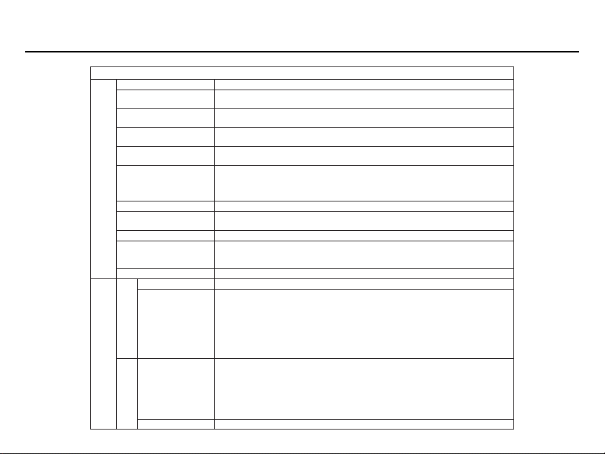
CONTENTS
SECTION DESCRIPTION PAGE
1 Specifications .............................................................................................................. 4
2 Preliminary Inspection ................................................................................................. 6
Introduction .................................................................................................................. 6
Receiving .................................................................................................................... 6
Nameplate Structure ................................................................................................... 7
3 Mounting Precautions ................................................................................................. 9
4Wiring........................................................................................................................... 10
Main Circuit Input/Output Wiring.................................................................................. 10
Control Circuit Wiring................................................................................................... 10
Grounding ................................................................................................................... 11
Te r minal Functions & Voltages ................................................................................... 12
5Peripheral Devices....................................................................................................... 13
Short Circuit Protection ............................................................................................... 13
Auxiliary Input/Output Power Options.......................................................................... 14
6 Conformance to European EMC Directive ................................................................. 15
7Drive Interconnection Diagrams ................................................................................. 16
Precautions ................................................................................................................. 16
2-Wire Control ............................................................................................................ 17
3-Wire Control ............................................................................................................ 18
8Drive Parameter Listing .............................................................................................. 19
9 Monitor Displays ......................................................................................................... 26
10 Drive Dimensions ....................................................................................................... 27
5
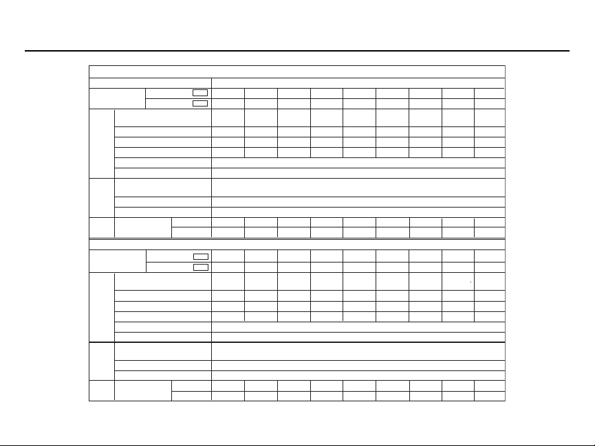
Drive Specifications Section 1
230V Class
Model CIMR-V7* 20P1 20P2 20P4 20P7 21P5 22P2 23P7 25P5 27P5
Max. applicable motor output
HP(1) and 1
Drive capacity (kVA) 0.3 0.6 1.1 1.9 3.0 4.2 6.7 9.5 13
Rated Output Current (A) 0.8 1.6 3.0 5.0 8.0 11.0 17.5 25 33
Output
Rated Input Current (A) 1.1 1.8 3.9 6.4 11.0 15.1 24.0 33.0 39.6
Max. Output Voltage (V) 200 to 230V (proportional to input voltage)
Characteristics
Max. Output Frequency (Hz) 400 Hz (programmable)
Rated Input Voltage and
Frequency
Allowable voltage fluctuation -15% to +10%
Power
Supply
Allowable frequency fluctuation ±5%
Cooling Method
istics
(QTY) NEMA 4 self self self self fan fan fan self self
Physical
Character-
460V Class
SECTION A.
MV A001 A002 A003 A005 A008 A011 A017 A025 A033
NEMA 1 self self self fan fan fan fan fan(2) fan(2)
Model No. Related Specifications
1/8 1/4 1/2
3/4
2357.5 10
3-phase. 200 to 230 V, 50/60 Hz
(5)
Model CIMR-V7* - - 40P2 40P4 40P7 41P5 42P2 43P7 45P5 47P5
Max. applicable motor
output HP(1)
Drive capacity (kVA) - - 0.9 1.4 2.6 3.7 4.2 7 11 16
Rated Output Current (A) - - 1.2 1.8 3.4 4.8 5.5 8.6 14.8 21
Output
Rated Input Current (A) - - 1.6 2.4 4.7 7.0 8.1 12.0 19.6 27.8
Characteristics
Max. Output Voltage (V) 380 to 460V (proportional to input voltage)
Max. Output Frequency (Hz) 400 Hz (programmable)
Rated Input Voltage and
Frequency
Allowable voltage fluctuation -15% to +10%
Power
Supply
Allowable frequency fluctuation ±5%
Cooling Method
istics
Physical
(QTY) NEMA 4 - - self self self fan - - fan self self
Character-
MV - - B001 B002 B003 B005 - - B009 B015 - -
- - 1/2 3/4 1&2 3 3 5
7.5 &
10
3-phase. 380 to 460 V, 50/60 Hz
NEMA 1 - - self
self self fan - - fan fan(2) fan(2)
(6)
15
(6
(6
(6
6
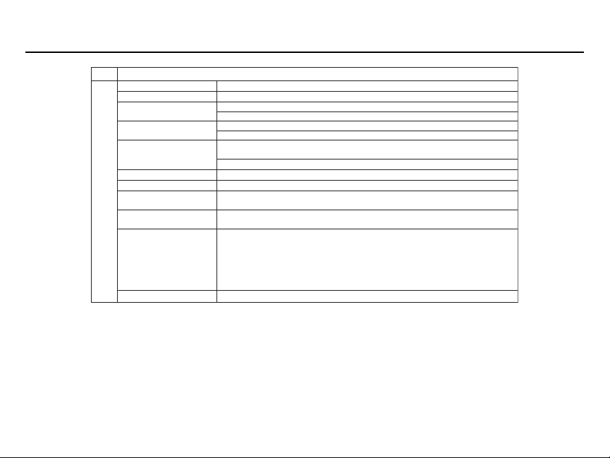
SpecificationsSection 1
Drive
Control method Sine wave PWM (V/f Control or Open Loop Vector)
SECTION B.
Frequency control range 0.1 to 400 Hz
Frequency accuracy Digital command: ±0.01% (14 to 122°F, -10 to +50°C)
(temperature change) Analog command: ±0.5% (77°F ± 18°F, 25°C ± 10°C)
Speed Regulation
Frequency setting resolution 0.1 Hz (100Hz or more)
Output frequency resolution
Overload capacity 150% of rated output current for 1 minute
Frequency Reference Signal
Accel/Decel Time
Control Characteristics
Braking Torque
V/f characteristics Custom V/f pattern
0 to 10VDC (20kΩ), 4 to 20mA (250Ω), 0 to 20mA (250Ω) pulse train input,
All Drives
Open Loop Vector: ±0.2%
V/Hz Mode: ±0.5% – 1% with Slip Compensation
Digital Operator reference: 0.01 Hz (< 100Hz)
Analog
reference: 0.06Hz/60Hz (1/1000)
0.01 Hz
Digital Operator Pot
(accel/decel time are independently programmed)
Continuous regenerative torque: Approx. 20% (150% with
optional braking resistor, braking transistor built-in)
0.01 to 6000 sec.
Short-term average deceleration torque (2)
0.2kW: 150%
0.75kW: 100%
1.5kW: 50%
2.2kW or more: 20%
See notes at end of table
(table continued on next page)
7
Drive
Specifications Section 1
Motor overload protection Electronic thermal overload relay
Instantaneous overcurrent
Overload
Overvoltage
Undervoltage
Momentary Power Loss
Heatsink overheat Protected by electronic circuit
Protective Functions
Stall prevention level
Ground fault Protected by electronic circuit (overcurrent level)
Power charge indication RUN lamp says ON or digital operator LED stays ON.
Cooling Fan Fault Protected by electronic circuit
Run/stop input 2-Wire or 3-Wire
Multi-function input
Input signalsOutput signals
Other Functions
Multi-function output (output frequency ≤ or ≥ set value), during overtorque detection,
8
Analog monitor 0 to +10VDC output, programmable for output frequency or output current
SECTION B.
All Drives (Continued)
Motor coasts to stop at approx. 250%
Motor coasts to stop after 1 min. at 150% of
Motor coasts to stop if DC bus voltage exceeds
Motor coasts to stop when DC bus voltage is
210VDC or less (230V), 400VDC or less (460V)
• Not provided (stops if power loss is 15 ms or longer)
• Automatic restart at recovery from 0.5 sec. power loss
Independently programmable during accel and
constant-speed running. Selectable during decel.
ON until the DC bus voltage becomes 50V or less.
Seven of the following input signals are selectable:
Forward/reverse run (3-Wire sequence), fault reset,
external fault (NO/NC contact input), multi-step speed operation,
external baseblock (NO/NC contact input, speed search command,
accel/decel hold command, LOCAL/REMOTE selection,
communication/control circuit terminal selection,
emergency stop fault emergency stop alarm
(1 NO/NC contact output, 2 photo-coupler outputs):
Fault, running, zero speed, at frequency, frequency detection
during undervoltage detection, minor error, during baseblock, operation mode,
inverter run ready, during fault retry, during UV, during speed search,
of drive current
drive rated current (7)
410VDC (230V), 820VDC (460V)
The following operations are selectable:
• Automatic restart
(Charge LED is Provided for 400V)
Jog command, accel/decel time select,
Following output signals are selectable
data output through communication
SpecificationsSection 1
Drive
SECTION B.
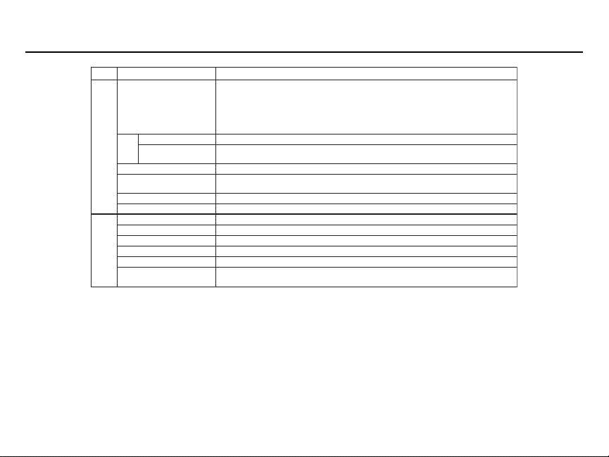
Standard functions
Status indicator LEDs RUN and ALARM LEDs provided as standard
Digital Operator
Display
Other Functions
Terminals Screw terminals for both main circuit and control circuit
Wiring distance between
drive and motor
Enclosure Open Type/NEMA type 1/NEMA type 4X/12
Cooling method Self-cooling/cooling fan
Ambient temperature 14 to 104°F (-10 to 40°C)
Humidity 95% RH or less (non-condensing)
Storage temperature (4) -4 to 140°F (-20 to 60°C)
Location Indoor (free from corrosive gases or dust)
Elevation 3,280 feet (1,000 m) or less
conditions
Environmental
Vibration
NOTES:
(1) Based on an N.E.C. standard 4-pole motor for max.applicable motor output.
(2) Shows deceleration torque for an uncoupled motor decelerating from 60 Hz in 0.1 seconds.
(3) Contact Yaskawa for wiring distances greater than 328 ft. (100 m).
(4) Temperature during shipping (for short periods of time).
(5) On NEMA type 4X/12 model only, maximum continuous rating of 30.8 A is 40 degrees C maximum ambient. For 33.0 A maximum
continuous rating, maximum ambient is 32 degrees C.
(6) Applies to NEMA type 4X/12 model only.
(7) On Model 47P5 NEMA type 4X/12 (21A), overload is 120% for 1 minute.
All Drives (Continued)
Open Loop Vector Control, full-range automatic torque boost, auto restart,
upper/lower frequency limit, DC injection braking current/time at start/stop,
frequency reference gain/bias, prohibited frequencies,
analog meter calibrating gain, S-curve accel/decel, slip compensation,
MODBUS communications (RS485/422, Max. 19.2K bps),
frequency reference from digital operator pot
Monitors frequency reference, output frequency,
output current, FWD/REF selection
328 ft (100 m) or less (3)
Up to 1G, at less than 20 Hz;
up to 0.2G, at 20 to 50 Hz
9

10

Preliminary
InspectionSection 2
oduction
Intr
This document pertains to the V7 ac drive. This document is equally applicable to drives identified as GPD315, GPD315/V7,
GPD315/V74X, and V74X. Additionally, in this document, the word “drive”, “ac drive”, and “inverter” may be used interchangeably. The V7 (NEMA type1) and V74X (NEMA type 4X/12), hereafter referred to as the "Drive," are general purpose sinecoded pulse width modulated AC motor drives which generate an adjustable voltage/frequency three phase output for complete speed control of most conventional squirrel cage induction motors. Automatic stall prevention and voltage boost prevent
nuisance tripping during load or line side transient conditions. The Drive will not induce any voltage line notching distortion
back to the utility line, and it maintains a displacement power factor of not less than 0.98 throughout its speed range.
When properly installed, operated and maintained, the Drive will provide a lifetime of service. It is mandatory that the person
who operates, inspects, or maintains this equipment thoroughly read and understand this manual before proceeding.
This installation guide details installation procedures and parameter setting ranges. For programming, refer to the Technical
Manual TM.V7.01 on the CD-ROM included with the Drive.
Receiving
Check nameplate - Be certain your input voltage source, motor and Drive nameplates are all marked either 230V or 460V.
Other voltages can be used, but require additional programming; see TM.V7.01.
11
Preliminary
Y
Y
Inspection Section 2
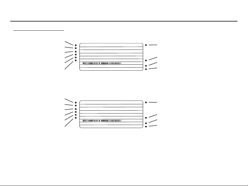
Nameplate Structure
MODEL NO.
REFERENCE
INPUT SPEC
OUTPUT SPEC
LOT NO.
SERIAL NO.
MODEL:
CIMR-V7AU23P7
MVA017
REF:
3PH 200-230VAC 50/60Hz 24A
INPUT:
3PH 0-230VAC MAX. 0-400Hz 17.5A
OUTPUT:
LOT NO.:
SER NO.: N8W0593-8-043/V9905
E131457FILE NO.:
INSTALLATION CATEGORY: II
SPEC:
MASS: 2.4kg
PRG: 8021
IP20
23P71
INVERTER SPEC
MASS
SOFTWARE NO.
INSTALLATION CATEGOR
V7 [NEMA type 1]
MODEL NO.
REFERENCE
INPUT SPEC
OUTPUT SPEC
LOT NO.
SERIAL NO.
MODEL:
CIMR-V7AU23P7
MVA017
REF:
3PH 200-230VAC 50/60Hz 24A
INPUT:
3PH 0-230VAC MAX. 0-400Hz 17.5A
OUTPUT:
LOT NO.:
SER NO.: N8W0593-8-043/V9905
E131457FILE NO.:
INSTALLATION CATEGORY: II
SPEC:
MASS: 2.4kg
PRG: 8021
IP20
23P71
INVERTER SPEC
MASS
SOFTWARE NO.
INSTALLATION CATEGOR
V74X [NEMA type 4X/12]
12
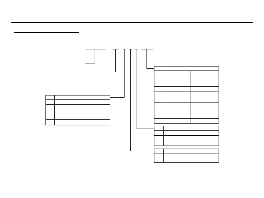
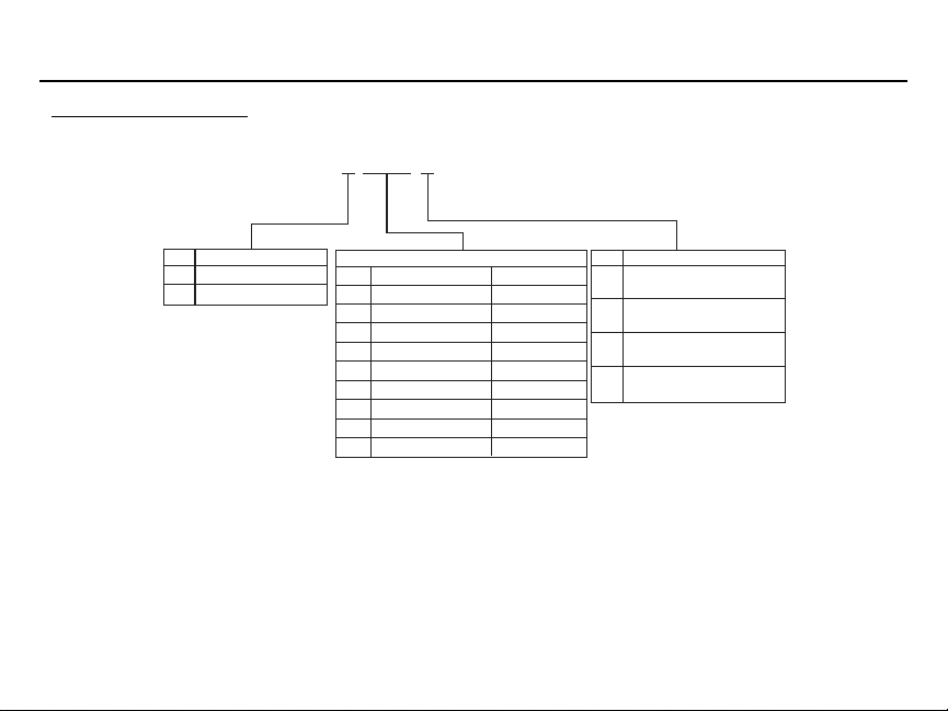
Model Number Structure
Preliminary
InspectionSection 2
C I M R - V 7 A M 2 3 P 7
DRIVE
V7 SERIES
No. Type
AWith digital operator
BWithout digital operator
CWith digital operator
R Finless
Note: Contact your YASKAWA representative
for finless type drives.
No. Applicable maximum motor output
230V 460V
0P1 1/8 HP ---
0P2 1/4 HP 1/2 HP
0P4 1/2 HP 3/4 HP
0P7 3/4 & 1 HP 1 & 2 HP
1P5 2 HP 3 HP
2P2 3 HP 3 HP
3P7 5 HP 5 HP
5P5 7.5 HP 7.5 & 10 HP
7P5 10 HP 15
No. Voltage Class
B Single-phase 230VAC
2 Three-phase 230VAC
4 Three-phase 460VAC
No. Specifications
U UL Specification (U.S.)
or M Specification)
(1)
Applies to NEMA type 4X12 model only
(1)
13

14
Drive Spec Structure
Preliminary
InspectionSection 2
2 3 P 7 1
B Single-phase 230VAC
2 Three-phase 230VAC
4
Three-phase 460VAC
Note: Model Number and Drive Spec Number are required to fully define a drive.
(1)
Applies to NEMA type 4X/12 model only.
No. Applicable maximum motor output
0P1 1/8 HP ---
0P2 1/4 HP 1/2 HP
0P4 1/2 HP 3/4 HP
0P7 3/4 & 1 HP 1 & 2 HP
1P5 2 HP 3 HP
2P2 3 HP 3 HP
3P7 5 HP 5 HP
5P5 7.5 7.5 & 10 HP
7P5 10 HP 10/15
230 V 460 V
(1)
HP
No. Protective structure
0 Open chassis
(IP20, IP00)
1 Enclosed wall-mounted
(NEMA 1)
4Water and dust tight
(NEMA 4/IP66)
7 Open chassis (IP20)
Top-closed type
15

Mounting Precautions Section 3
Location of the Drive is important to achieve proper performance and normal operating life. The unit should be installed in an
area where it will be protected from:
• Extreme cold and heat. Use only within the ambient temperature range (for open chassis
type): 14 to 122°F (-10 to +50°C) (for enclosed wall mount type): 14 to 104°F (10 to +40°C)
• Rain, moisture
• Oil sprays, splashes
• Salt spray
• Direct sunlight. (Avoid using outdoors)
• Corrosive gases (e.g. sulfurized gas) or liquids
• Dust or metallic particles in the air
• Physical shock, vibration
• Magnetic noise (Example: welding machines, power devices, etc.)
• High humidity
• Radioactive substances
• Combustibles: thinner, solvents, etc.
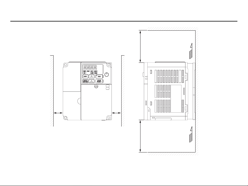
When preparing to mount the Drive, lift it by its base, never by the front cover. For effective cooling, as well as proper maintenance, the Drive must be installed on a flat, non-flammable vertical surface (wall or panel) using recommended mounting
screws. There MUST be a MINIMUM 3.9 in. clearance above and below the Drive to allow air flow over the heat sink fins.
A minimum 1.2 in. clearance is required on each side of the Drive.
16
Mounting
PrecautionsSection 3
3.94 in.
(100mm)
30mm30mm
3.94 in.
(100mm)
Important: To use the CIMR-V7*U25P5, 27P5, 45P5, and 47P5 Drives
as an open chassis, remove top and bottom covers.
AIR
AIR
17
Wiring Main and Control Circuit Section 4
Main Circuit Input /Output Wiring
• Use 600V vinyl-sheathed wire or equivalent. Wire size and type should be determined by local electrical codes.
•Avoid routing power wiring near equipment sensitive to electrical noise.
•Avoid running input and output wiring in the same conduit.
• NEVER connect AC main power to output terminals T1(U), T2(V), and T3(W).
• NEVER allow wire leads to contact metal surfaces. Shor t-circuit may result.
• NEVER connect power factor correction capacitors to the Drive output. Consult Yaskawa when connecting noise
filters to the Drive output.
• WIRE SIZING MUST BE SUITABLE FOR CLASS I CIRCUITS.
• When connecting motor to Drive’s output terminals, include a separate ground wire. Attach ground wire solidly to
motor frame and to Drive’s ground terminal .
• When using armored or shielded cable for connection between Drive and motor, solidly connect armor or shield
to motor frame, and to Drive’s ground terminal .
• Motor lead length should NOT EXCEED 164 feet (50 meters), and motor wiring should be run in a separate conduit from the power wiring. If lead length must exceed this distance, reduce carrier frequency (see TM.V7.01,
paragraph 5.8) and consult factory for proper installation procedures.
• Use UL listed closed loop connectors or CSA certified ring connectors sized for the selected wire gauge. Install
connectors using the correct crimp tool recommended by the connector manufacturer.
ol Circuit
Contr
All basic control circuit (signal) interconnections are shown in the appropriate diagram:
• Interconnections for external two-wire control in combination with the Digital Operator are shown in Figure 1-5.
• Interconnections for external three-wire control in combination with the Digital Operator are shown in Figure 1-6.
Make wire connections according to Figures 1-5 and 1-6 and Table 1-2; obser ve the following:
• Signal Leads: Terminals S1-S7 & SC; RP, FS, FR & FC; R+, R-, S+, S-; & AM & AC.
• Control Leads: Terminals P1, P2 & PC; MA, MB & MC.
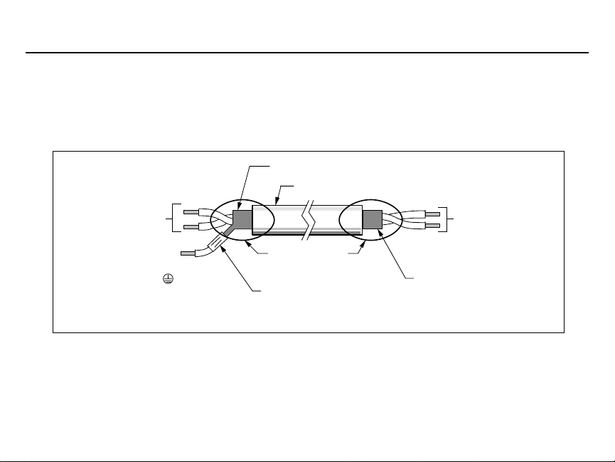
• Use twisted shielded or twisted-pair shielded wire (20-16 AWG [0.5 – 1.25mm2]) for control and signal circuit
leads. The shield sheath MUST be connected at the drive end ONLY (terminal ). The other end should be
dressed neatly and left unconnected (floating). See Figure 1-1.
18
Main and Control CircuitSection 4
• Signal leads and feedback leads (PG) must be separated from control leads main circuit leads, and any other
power cables, to prevent erroneous operation caused by electrical noise.
• Lead length should NOT EXCEED 164 feet (50 meters). Wire sizes should be determined considering the voltage
drop.
• All AC relays, contactors and solenoids should have RC surge supressors installed across their coils.
• All DC relays, contactors and solenoids should have diodes installed across their coils.
SHIELD SHEATH
OUTER JACKET
Wiring
TO DRIVE
SIGNAL
TERMINALS
TO SHIELD
SHEATH
TERMINAL
(TERM. )
WRAP BOTH ENDS
OF SHEATH WITH
INSULATING TAPE
CRIMP
CONNECTION
Figure 1-1. Shielded Sheath Termination
DO NOT
CONNECT
TO
EXTERNAL
CIRCUIT
19
Wiring Grounding Section 4
• The Drive must be solidly grounded using the main circuit ground terminal .
• If Drive is installed in a cabinet with other equipment, ground leads for all equipment should be connected to a
common low-impedance ground point within the cabinet.
• The supply neutral should be connected to the ground point within the cabinet.
• Select appropriate ground wire size from Table 1-1.
• Make all ground wires as short as practical.
• NEVER ground the Drive in common with welding machines, or other high power electrical equipment.
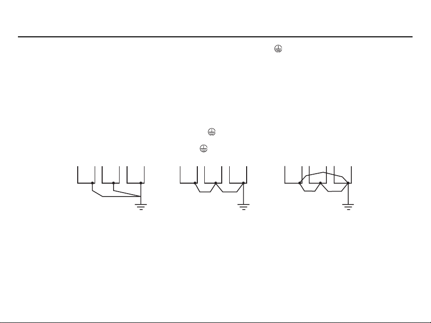
• Where several Drives are used, ground each directly to the ground point (see Figure 1-2). DO NOT FORM A
LOOP WITH THE GROUND LEADS.
• When connecting a motor to the Drive’s output terminals, include a separate ground wire. Attach ground wire
solidly to motor frame and to Drive’s ground terminal .
• When using armored or shielded cable for connection between Drive and motor, solidly connect armor or shield
to motor frame, and to the Drive’s ground terminal .
CORRECT CORRECT NOT
ACCEPTABLE
Figure 1-2. Correct Ground Connection
20
Loading...