

Page 1
PUT
VOLUME
2
Page 2
FCC INFORMATION (U.S.A)
1. IMPORTANT NOTICE : DO NOT MODIFY THIS UNIT!
This product, when installed as indicated in the instructions contained in this manual, meets FCC requirements. Modifications not expressly
approved by Yamaha may void your authority, granted by the FCC, to use the product.
2. IMPORTANT: When connecting this product to accessories and/or another product use only high quality shielded cables. Cable/s
supplied with this product MUST be used. Follow all installation instructions. Failure to follow instructions could void your FCC
authorization to use this product in the USA.
3. NOTE: This product has been tested and found to comply with the requirements listed in FCC Regulations, Part 15 for Class “B” digital
devices. Compliance with these requirements provides a reasonable level of assurance that your use of this product in a residential
environment will not result in harmful interference with other electronic devices. This equipment generates/uses radio frequencies and, if
not installed and used according to the instructions found in the user’s manual, may cause interference harmful to the operation of other
electronic devices. Compliance with FCC regulations does not guarantee that interference will not occur in all installations. If this product
is found to be the source of interference, which can be determined by turning the unit “OFF” and “ON”, please try to eliminate the problem
by using one of the following measures:
Relocate either this product or the device that is being affected by the interference.
Utilize power outlets that are on different branch (circuit breaker or fuse) circuits or install AC line filter/s.
In the case of radio or TV interference, relocate/reorient the antenna. If the antenna lead-in is 300 ohm ribbon lead, change the lead-in to
co-axial type cable.
If these corrective measures do not produce satisfactory results, please contact the your local retailer authorized to distribute this type of
product. If you can not locate the appropriate retailer, please contact Yamaha Corporation of America, Electronic Service Division, 6600
Orangethorpe Ave, Buena Park, CA 90620
The above statements apply ONLY to those products distributed by Yamaha Corporation of America or its subsidiaries.
*
NEDERLAND / NETHERLAND
• Dit apparaat bevat een lithium batterij voor geheugen back-up.
• This apparatus contains a lithium battery for memory back-up.
• Raadpleeg uw leverancier over de verwijdering van de batterij op
het moment dat u het apparaat ann het einde van de levensduur
afdankt of de volgende Yamaha Service Afdeiing:
Yamaha Music Nederland Service Afdeiing
Kanaalweg 18-G, 3526 KL UTRECHT
Tel. 030-2828425
• For the removal of the battery at the moment of the disposal at the
end of the service life please consult your retailer or Yamaha
Service Center as follows:
Yamaha Music Nederland Service Center
Address : Kanaalweg 18-G, 3526 KL UTRECHT
Tel : 030-2828425
• Gooi de batterij niet weg, maar lever hem in als KCA.
• Do not throw away the battery. Instead, hand it in as small chemical
waste.
ADVARSEL!
Lithiumbatteri—Eksplosionsfare ved fejlagtig håndtering.
Udskiftning må kun ske med batteri af samme fabrikat og type.
Levér det brugte batteri tilbage til leverandoren.
VARNING
Explosionsfara vid felaktigt batteribyte. Använd samma
batterityp eller en ekvivalent typ som rekommenderas av
apparattillverkaren. Kassera använt batteri enligt fabrikantens
instruktion.
VAROITUS
Paristo voi räjähtää, jos se on virheellisesti asennettu. Vaihda
paristo ainoastaan laitevalmistajan suosittelemaan tyyppiin.
Hävitä käytetty paristo valmistajan ohjeiden mukaisesti.
Page 3
SPECIAL MESSAGE SECTION
This product utilizes batteries or an external power supply
(adapter). DO NOT connect this product to any power supply or adapter other than one described in the manual, on
the name plate, or specifically recommended by Yamaha.
WARNING: Do not place this product in a position where
anyone could walk on, trip over, or roll anything over
power or connecting cords of any kind. The use of an
extension cord is not recommended! If you must use an
extension cord, the minimum wire size for a 25' cord (or
less ) is 18 AWG. NOTE: The smaller the AWG number,
the larger the current handling capacity. For longer extension cords, consult a local electrician.
This Product should be used only with the components
supplied or; a cart, rack, or stand that is recommended by
Yamaha. If a cart, etc., is used, please observe all safety
markings and instructions that accompany the accessory
product.
SPECIFICATIONS SUBJECT TO CHANGE: The information contained in this manual is believed to be correct
at the time of printing. However, Yamaha reserves the right
to change or modify any of the specifications without notice or obligation to update existing units.
This product, either alone or in combination with an amplifier and headphones or speaker/s, may be capable of producing sound levels that could cause permanent hearing loss.
DO NOT operate for long periods of time at a high volume
level or at a level that is uncomfortable. If you experience
any hearing loss or ringing in the ears, you should consult
an audiologist. IMPORTANT: The louder the sound, the
shorter the time period before damage occurs.
Some Yamaha products may have benches and/or accessory mounting fixtures that are either supplied with the
product or as optional accessories. Some of these items are
designed to be dealer assembled or installed. Please make
sure that benches are stable and any optional fixtures
(where applicable) are well secured BEFORE using.
Benches supplied by Yamaha are designed for seating only.
No other uses are recommended.
goals. In keeping with both the letter and the spirit of the
law, we want you to be aware of the following:
Battery Notice: This product MAY contain a small nonrechargeable battery which (if applicable) is soldered in
place. The average life span of this type of battery is approximately five years. When replacement becomes necessary, contact a qualified service representative to perform
the replacement.
This Product may also use “household” type batteries.
Some of these may be rechargeable. Make sure that the
battery being charged is a rechargeable type and that the
charger is intended for the battery being charged.
When installing batteries, do not mix old batteries with
new, or with batteries of a different type. Batteries MUST
be installed correctly. Mismatches or incorrect installation
may result in overheating and battery case rupture.
Warning: Do not attempt to disassemble, or incinerate any
battery. Keep all batteries away from children. Dispose of
used batteries promptly and as regulated by the laws in
your area.
Note: Check with any retailer of household type batteries
in your area for battery disposal information.
Disposal Notice: Should this Product become damaged
beyond repair, or for some reason its useful life is considered to be at an end, please observe all local, state, and
federal regulations that relate to the disposal of products
that contain lead, batteries, plastics, etc. If your dealer is
unable to assist you, Please contact Yamaha directly.
NAME PLATE LOCATION: The name Plate is located
on the top of the product. The model number, serial
number, power requirements, etc., are located on this plate.
You should record the model number, serial number, and
the date of purchase in the spaces provided below and
retain this manual as a permanent record of your purchase.
NOTICE: Service charges incurred due to lack of knowledge relating to how a function or effect works (when the
unit is operating as designed) are not covered by the manufacturer’s warranty, and are therefore the owners responsibility. Please study this manual carefully and consult your
dealer before requesting service.
ENVIRONMENTAL ISSUES: Yamaha strives to produce products that are both user safe and environmentally
friendly. We sincerely believe that our products and the
production methods used to produce them, meet these
PLEASE KEEP THIS MANUAL
92-BP
Model
Serial No.
Purchase Date
Page 4

WELCOME TO THE MU90R
Welcome to the MU90R
Congratulations and thank you for purchasing the Yamaha MU90R Tone
Generator!
The MU90R is an advanced tone generator providing 779 high-quality
Voices, full General MIDI compatibility — including Yamaha’s new XG-
MIDI (Extended General MIDI) — plus flexible computer interfacing
in a rack-mount unit.
With the convenient built-in host computer interface and MIDI ter-
minals, the MU90R is ideal for any computer music system — from connection to a simple laptop to integration in a complete MIDI studio. With
its large LCD and the intuitive graphic controls on the display, the MU90R
is remarkably easy to use.
The MU90R also features completely independent dual MIDI inputs,
32 Part multi-timbral capacity and full 64-note polyphony for playback
of even the most sophisticated song data. A special Performance mode
gives you flexible four-Voice operation, for live performance applications.
Built-in digital multi-effects give you enormous versatility in “sweeten-
ing” the sound. Plus, the convenient A/D inputs allow you to connect a microphone, electric guitar or other instrument, and mix those signals with the
MU90R’s Voices. What’s more, the MU90R provides a host of comprehensive, yet easy-to-use editing tools for getting just the sound you need.
ii
Page 5

TABLE OF CONTENTS
Table of Contents
Welcome to the MU90R......................................................................................................... ii
Unpacking .............................................................................................................................. iii
Table of Contents ................................................................................................................... iv
How to Use This Manual .....................................................................................................vii
Precautions...........................................................................................................................viii
The Controls of the MU90R .................................................................................................. 1
Front Panel .................................................................................................................... 1
Rear Panel ..................................................................................................................... 3
The MU90R — What It Is and What It Can Do ................................................................. 4
What It Is…....................................................................................................................... 4
About General MIDI..................................................................................................... 4
What It Can Do…............................................................................................................. 5
Using With MIDI Keyboard ......................................................................................... 5
Using With a Computer or Sequencer .......................................................................... 5
About the Modes of the MU90R...................................................................................... 6
Play Modes and the Part Controls................................................................................. 6
Utility Mode................................................................................................................ 11
Part Edit Mode ............................................................................................................ 11
GUIDED TOUR
Setting Up Your MU90R ................................................................................................ 14
What Y ou’ll Need.................................................................................................. 14
Making the Connections ....................................................................................... 14
Powering Up and Playing the Demo Song.................................................................... 16
Powering Up ............................................................................................................... 16
Playing the Demo Song .............................................................................................. 17
Playing Your MU90R with a MIDI Keyboard ............................................................. 18
Selecting V oices............................................................................................................... 19
Changing the Voice Bank............................................................................................ 20
Selecting Voices From Your MIDI Keyboard ............................................................. 21
Changing Some of the Settings — Part Controls ........................................................ 22
Selecting Another Part and Changing its MIDI Channel............................................ 22
Changing the Volume and Pan Settings of a Part ....................................................... 24
Using Mute/Solo.............................................................................................................. 25
Using the A/D Input........................................................................................................ 26
Setting Up the MU90R in Your Music System............................................................. 29
Connecting With a Computer ..................................................................................... 29
Macintosh .............................................................................................................. 29
IBM PC/AT and Clones ........................................................................................ 30
Connecting to Other MIDI Devices............................................................................ 31
Using the MU90R with a MIDI Data Storage Device ................................................. 33
Data Flow Block Diagram.............................................................................................. 34
MIDI/Computer Connecting Cables............................................................................. 35
iv
Page 6

TABLE OF CONTENTS
REFERENCE
Multi Mode...................................................................................................................... 38
Multi Play Mode ......................................................................................................... 39
Play Displays .............................................................................................................. 39
Part Controls ............................................................................................................... 40
Single Part Control...................................................................................................... 41
Selecting Single Part Control ................................................................................ 41
Editing in Single Part ............................................................................................ 41
All Part Control........................................................................................................... 46
Editing in All Part.................................................................................................. 46
Multi Edit Mode.......................................................................................................... 49
Filter ...................................................................................................................... 49
EG (Envelope Generator)...................................................................................... 52
EQ (Equalizer) ...................................................................................................... 57
Vibrato................................................................................................................... 59
Others .................................................................................................................... 61
Drum Setup Controls............................................................................................. 73
Calling Up the Drum Setup Menu................................................................... 73
Drum Setup Parameters ................................................................................... 75
Performance Mode ......................................................................................................... 80
Performance Play Mode.............................................................................................. 80
Selecting a Performance and its Individual Parts.................................................. 81
Performance Part Control ........................................................................................... 83
Single Part ............................................................................................................. 83
All Part .................................................................................................................. 86
Performance Edit Mode .............................................................................................. 89
Common ................................................................................................................ 89
Part ........................................................................................................................ 93
Filter ...................................................................................................................... 94
EG ......................................................................................................................... 94
EQ ......................................................................................................................... 94
Vibrato................................................................................................................... 95
Others .................................................................................................................... 95
Copy and Store Operations ......................................................................................... 97
Copy ...................................................................................................................... 97
Store ...................................................................................................................... 98
Recall Function ................................................................................................... 100
Effect Edit Mode........................................................................................................... 101
Reverb (REV) ........................................................................................................... 101
Chorus ....................................................................................................................... 103
Variation .................................................................................................................... 104
Insertion 1, 2 ............................................................................................................. 106
About the Effect Connections — System and Insertion ........................................... 109
Equalizer (EQ) Edit...................................................................................................... 112
Utility Mode .................................................................................................................. 114
System Functions ...................................................................................................... 114
GUIDED TOUR
REFERENCE
APPENDIX
v
Page 7

TABLE OF CONTENTS
Dump Out Functions................................................................................................. 119
Saving and Restoring Data via MIDI.................................................................. 119
Saving and Restoring Data via TO HOST .......................................................... 119
Initialize Functions ................................................................................................... 122
Demo Song Play (DEMO) ........................................................................................ 125
Sound Module Mode (MODE) ................................................................................. 126
Show Control Change ............................................................................................... 127
Show Exclusive......................................................................................................... 128
About Cable Messages ........................................................................................ 129
XG .................................................................................................................................. 132
Chapter 0: Format Overview .................................................................................... 132
Chapter 1: MIDI Specifications ................................................................................ 135
Troubleshooting ............................................................................................................ 147
Error Messages ............................................................................................................. 148
Specifications................................................................................................................. 149
Glossary ......................................................................................................................... 151
Index .............................................................................................................................. 153
APPENDIX
vi
Page 8

How to Use This Manual
You are probably eager to try out your new MU90R Tone Generator right
away and hear what it can do, rather than have to read through a lot of instructions before you can even get a sound out of it.
However, to get the most out of your MU90R, we strongly suggest that
you read the following sections in the order given:
1) Precautions
This gives you important information on how to care for your new
MU90R, how to avoid damaging, and how to ensure long-term, reli-
able operation.
2) The Controls of the MU90R
This section introduces you to the panel controls and connectors.
3) The MU90R — What It Is and What It Can Do
This briefly provides an overview of the functions and features of the
MU90R and offers some important hints on how you can use it effec-
tively.
HOW TO USE THIS MANUAL
4) Guided Tour
This very important section gets you started using your new MU90R. It
helps you set up the instrument, play it, and use some of the more im-
portant functions and features. The hands-on experience you gain in
this section will help you navigate through the other sections of the
manual.
5) Setting Up the MU90R in Your Music System;
Using the MU90R with a Computer
These sections (within the Guided Tour) provide all you need to know
to effectively integrate the MU90R into your present computer music
system.
6) Reference
Once you’re familiar with everything above, lightly go over this com-
prehensive guide to all editing functions. You won’t need (or want) to
read everything at once, but it is there for you to refer to when you need
information about a certain feature or function.
7) Appendix
Finally, use the sections in the Appendix as necessary. For example, the
Index will come in handy when you need to quickly find information
on a specific topic. Other sections, such as the Glossary, Trouble-
shooting and Error Messages provide additional useful information.
vii
Page 9
PRECAUTIONS
PLEASE READ CAREFULLY BEFORE PROCEEDING
* Please keep these precautions in a safe place for future reference.
WARNING
Always follow the basic precautions listed below to avoid the possibility of serious injury or even death from electrical
shock, short-circuiting, damages, fire or other hazards. These precautions include, but are not limited to, the following:
• Do not open the instrument or attempt to disassemble the internal parts or
modify them in any way. The instrument contains no user-serviceable
parts. If it should appear to be malfunctioning, discontinue use immediately
and have it inspected by qualified Yamaha service personnel.
• Do not expose the instrument to rain, use it near water or in damp or wet
conditions, or place containers on it containing liquids which might spill
into any openings.
• If the AC adaptor cord or plug becomes frayed or damaged, or if there is a
sudden loss of sound during use of the instrument, or if any unusual
smells or smoke should appear to be caused by it, immediately turn off
CAUTION
the power switch, disconnect the adaptor plug from the outlet, and have
the instrument inspected by qualified Yamaha service personnel.
• Use the specified adaptor (PA-3B) only. Using the wrong adaptor can
result in damage to the instrument or overheating.
• Before cleaning the instrument, always remove the electric plug from the
outlet. Never insert or remove an electric plug with wet hands.
• Check the electric plug periodically and remove any dirt or dust which
may have accumulated on it.
Always follow the basic precautions listed below to avoid the possibility of physical injury to you or others, or damage
to the instrument or other property. These precautions include, but are not limited to, the following:
• Do not place the AC adaptor cord near heat sources such as heaters or
radiators, and do not excessively bend or otherwise damage the cord,
place heavy objects on it, or place it in a position where anyone could
walk on, trip over, or roll anything over it.
• When removing the electric plug from an outlet, always hold the plug
itself and not the cord.
• Do not connect the instrument to an electrical outlet using a multipleconnector. Doing so can result in lower sound quality, or possibly cause
overheating in the outlet.
• Remove the adaptor plug from the outlet when the instrument is not to be
used for extended periods of time, or during electrical storms.
• Before connecting the instrument to other electronic components, turn off
the power for all components. Before turning the power on or off for all
components, set all volume levels to minimum.
• Do not expose the instrument to excessive dust or vibrations, or extreme
cold or heat (such as in direct sunlight, near a heater, or in a car during
the day) to prevent the possibility of panel disfiguration or damage to the
internal components.
•Do not use the instrument near other electrical products such as televisions,
radios, or speakers, since this might cause interference which can affect
proper operation of the other products.
• Do not place the instrument in an unstable position where it might
accidentally fall over.
• Before moving the instrument, remove all connected adaptor and other
cables.
• When cleaning the instrument, use a soft, dry cloth. Do not use paint
thinners, solvents, cleaning fluids, or chemical-impregnated wiping cloths.
Also, do not place vinyl or plastic objects on the instrument, since this
might discolor the panel or keyboard.
• Do not rest your weight on, or place heavy objects on the instrument, and
do not use excessive force on the buttons, switches or connectors.
• Use only the stand/rack specified for the instrument. When attaching the
stand or rack, use the provided screws only. Failure to do so could cause
damage to the internal components or result in the instrument falling over.
• Do not operate the instrument for a long period of time at a high or
uncomfortable volume level, since this can cause permanent hearing loss.
If you experience any hearing loss or ringing in the ears, consult a
physician.
■REPLACING THE BACKUP BATTERY
• This instrument contains a non rechargeable internal backup battery which
permits internal data to remain stored even when the power is off. When
the backup battery needs replacing, the message “Battery Low!” will display
in the display. When this happens, immediately back up your data (using
an external device such as the floppy disk-based Yamaha MIDI Data Filer
MDF2), then have qualified Yamaha service personnel replace the backup
battery.
•Do not attempt to replace the backup battery yourself, in order to prevent
the possible serious hazards. Always have qualified Yamaha service
personnel replace the backup battery.
• Never place the backup battery in a location that a child can reach, since
a child might accidentally swallow the battery. If this should happen,
consult a physician immediately.
■SAVING USER DATA
• Save all data to an external device such as the Yamaha MIDI Data Filer
MDF2, in order to help prevent the loss of important data due to a
malfunction or user operating error.
Yamaha cannot be held responsible for damage caused by improper
use or modifications to the instrument, or data that is lost or destroyed.
Always turn the power off when the instrument is not in use.
viii
Page 10
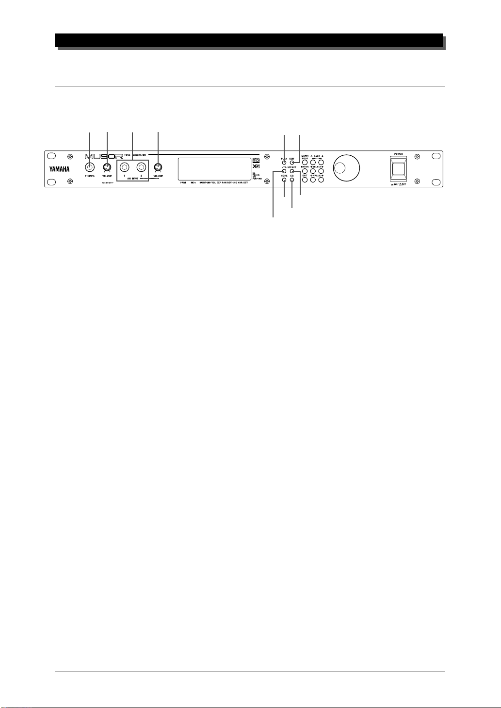
The Controls of the MU90R
Front Panel
THE CONTROLS OF THE MU90R
2
1
4
3
58
9
7
10
6
1 PHONES jack
For connection to a set of stereo headphones (1/4”).
2 VOLUME control
Turning this adjusts the overall volume of the MU90R.
3 A/D INPUT 1, 2 jacks
For connection of a microphone, electric guitar or other electronic instruments
(mono 1/4” plugs).
4 A/D INPUT level control
For control of the level of the A/D inputs.
5 PLAY button
For entering the Play mode and switching among the different Play displays.
(See page 39.)
6 UTIL (UTILITY) button
For entering the Utility mode. (See page 114.)
7 MODE button
For entering the Sound Module mode. (See page 126.)
8 EDIT button
For entering the Edit mode. (See pages 49 and 89.)
9 EFFECT button
For entering the Effect Edit mode. (See page 101.)
10 EQ button
For entering the EQ Edit mode. (See page 112.)
1
Page 11
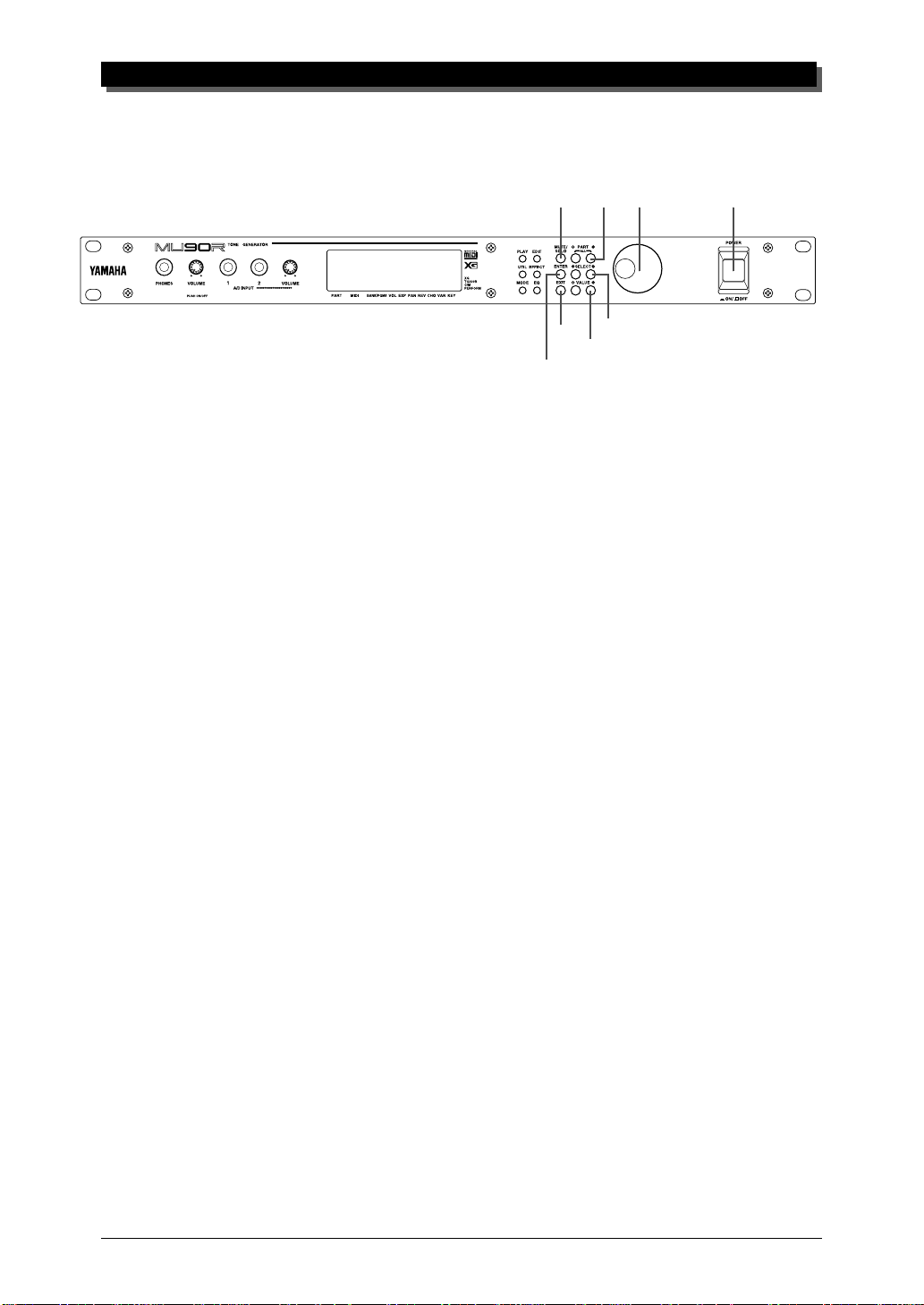
THE CONTROLS OF THE MU90R
14
17
18
11 MUTE/SOLO button
Pressing this alternately mutes or solos the selected Part. (See page 25.)
12 ENTER button
For calling up menu items in the display and for executing certain functions
and operations. Double-clicking this (pressing it twice quickly) calls up the
System Exclusive hexadecimal message for the current function and parameter value.
11
13
12
15
16
13 EXIT button
For leaving various display pages and returning to previous displays. Also for
canceling certain functions and operations.
14 PART -/+ buttons
For selecting different Parts. In the Effect Edit mode, these can be used to
switch among the different effects. Pressing these together enters and exits
from All Part control. (See page 46.)
15 SELECT </> buttons
For selecting the various menu items, parameters and controls on the display.
16 VALUE -/+ buttons
For changing the value of a selected parameter or control.
17 DATA dial
For adjusting/changing values of the selection function or parameter. Rotate
this clockwise to increase the value.
18 POWER switch
Pressing this turns the power on and off.
2
Page 12
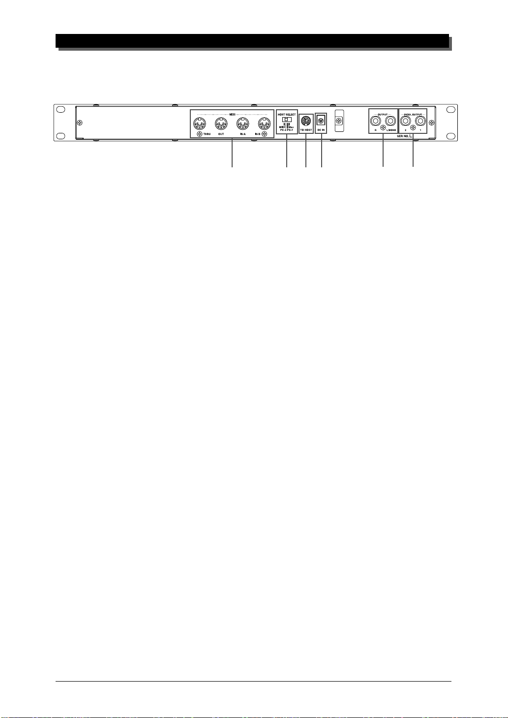
Rear Panel
THE CONTROLS OF THE MU90R
1
1 MIDI THRU, MIDI OUT and MIDI IN A/B terminals
For connection to other MIDI devices, such as a MIDI keyboard, tone generator, sequencer, or to a computer that has a MIDI interface. MIDI IN A and B
are independent MIDI ports, allowing full 32-channel MIDI input. MIDI OUT
is for data dumps to another MIDI device, while MIDI THRU is for “daisychain” connection of additional MU90Rs or other MIDI instruments. (See
page 14 for more information on MIDI connections.)
2 HOST SELECT switch
For selecting the type of host computer. (See page 29.)
3 TO HOST terminal
For connection to a host computer that does not have a MIDI interface. (See
page 31.)
4 DC IN jack
For connection to the PA-3B AC power adaptor.
2
34
56
5 OUTPUT L, R jacks
For connection to a stereo amplifier/speaker system. When using a mono system, connect it to the L/MONO jack.
6 INDIV. OUTPUT 1, 2 jacks
For independent output of selected Parts (1/4”). Parts selected for output
through these jacks are not output through the main OUTPUT or PHONES
jacks. (See pages 72 and 79.)
3
Page 13

THE MU90R — WHAT IT IS AND WHAT IT CAN DO
The MU90R — What It Is and What It Can Do
What It Is…
The MU90R is a fulll-featured and easy-to-use tone generator. It features
full General MIDI Level 1 compatibility with 128 General MIDI Voices
and 9 drum kits. It also provides new XG-MIDI (Extended General MIDI)
compatibility, with a total of 586 Voices and 20 drum kits. The MU90R has
64-note polyphony and is 32-Part multi-timbral. In other words, the
MU90R has 32 different Parts, each with its own Voice, so that up to 32
different Voices can be sounded simultaneously. Since the MU90R features
dual MIDI input ports (A and B), 16 Parts can be played from one MIDI
port and the remaining 16 from the other port.
The MU90R also has a TO HOST terminal for easy interfacing with a
computer, allowing you to play the Voices using your favorite music software. This is where the advanced multi-timbral capabilities come in, letting you playing sophisticated arrangements using up to 32 different Voices
at the same time.
The MU90R also features a special Performance mode, in which four
Parts are played simultaneously over a single MIDI channel. Connected to a
MIDI keyboard, this effectively gives you four tone generators in one. The
MU90R gives you 100 factory-programmed Preset Performances plus 100
Internal Performance locations for your own original Performances.
About General MIDI
General MIDI is a new addition to the worldwide MIDI standard. MIDI, as
you know, stands for Musical Instrument Digital Interface, and makes it
possible for various electronic musical instruments and other devices to
“communicate” with each other. For example, by connecting a sequencer
to the MU90R’s MIDI IN terminal, you could play back a song on the
sequencer using the Voices of the MU90R.
So, where does General MIDI fit in all of this? One of the most important features of General MIDI is in the standardization of Voices. This
means that a song recorded in the General MIDI format can be played back
on any General MIDI compatible tone generator and sound just as the composer intended. For example, if there is an alto sax solo in the song, it will
be played by an alto sax Voice on the General MIDI tone generator (and
not by a tuba or harpsichord!). Since the MU90R is fully compatible with
General MIDI, you can take advantage of the vast wealth of musical material recorded in that format.
4
Page 14

What It Can Do…
Here are a few ideas on how you can use the MU90R. The list below is not
comprehensive, but is meant to be a general guide to the possibilities and
provide a starting point or springboard for your own creative ideas and explorations.
Using With MIDI Keyboard
Use the MU90R as supplementary tone generator with your MIDI keyboard and play the Voices of both instruments in a layer together. Or, use
the convenient Performance mode, and play four Voices on the MU90R at
once. You can split the four Voices across the keyboard, playing each from
a different register. Or you can create sophisticated velocity splits, in which
a different Voice is heard depending on how strongly you play the keyboard. Or use keyboard and velocity splits together for even greater flexibility.
THE MU90R — WHAT IT IS AND WHAT IT CAN DO
Using With a Computer or Sequencer
Home Studio Setup
The MU90R integrates instantly and easily into any existing setup. If you
have a MIDI keyboard, computer and sequencing software, the MU90R
with its high-quality Voices and multi-timbral capabilities can expand your
home studio system.
Take It With You
If you have a laptop computer (and sequencing software), simply connect
the MU90R, plug in some headphones and you’ve got a complete, highpowered music making system that’s exceptionally easy to use. Use it for
composing, arranging, practicing or making/playing demos for your band.
Multimedia
Since it’s compatible with General MIDI, the MU90R is a natural for multimedia applications. Since the computer interface is built-in to the MU90R,
it hooks up instantly and easily to the computer’s serial port or printer port,
without the need for any other equipment.
5
Page 15
THE MU90R — WHAT IT IS AND WHAT IT CAN DO
About the Modes of the MU90R
The MU90R has two main operating modes: Multi and Performance. In
Multi mode, the MU90R is a 32-Part multi-timbral tone generator; in Performance mode, the MU90R effectively functions as four tone generators
controlled over a single MIDI channel.
Which mode the MU90R is in depends on the selected Sound Module
mode. If XG, TG300B or C/M are selected, the MU90R automatically sets
itself to the Multi mode. When PFM is selected, the MU90R is in the Performance mode.
Sound Module Mode
XG
TG300B
C/M
Performance
The bottom right of the display indicates the currently selected Sound Module mode.
Selected Sound Module mode.
Play Modes and the Part Controls
Once the operating mode of the MU90R is set (Multi or Performance),
there are two main ways you can use the MU90R: playing and editing. In
the Play modes, you play the Voices; in the various Edit modes, you change
their settings.
Within the Play modes are the Part controls. These let you make basic settings for the Parts. The Single Part controls allow you to make independent
settings for each Part, while the All Part controls allow you to change the overall settings of all Parts. (See pages 41 and 46 for more information.)
6
Page 16
THE MU90R — WHAT IT IS AND WHAT IT CAN DO
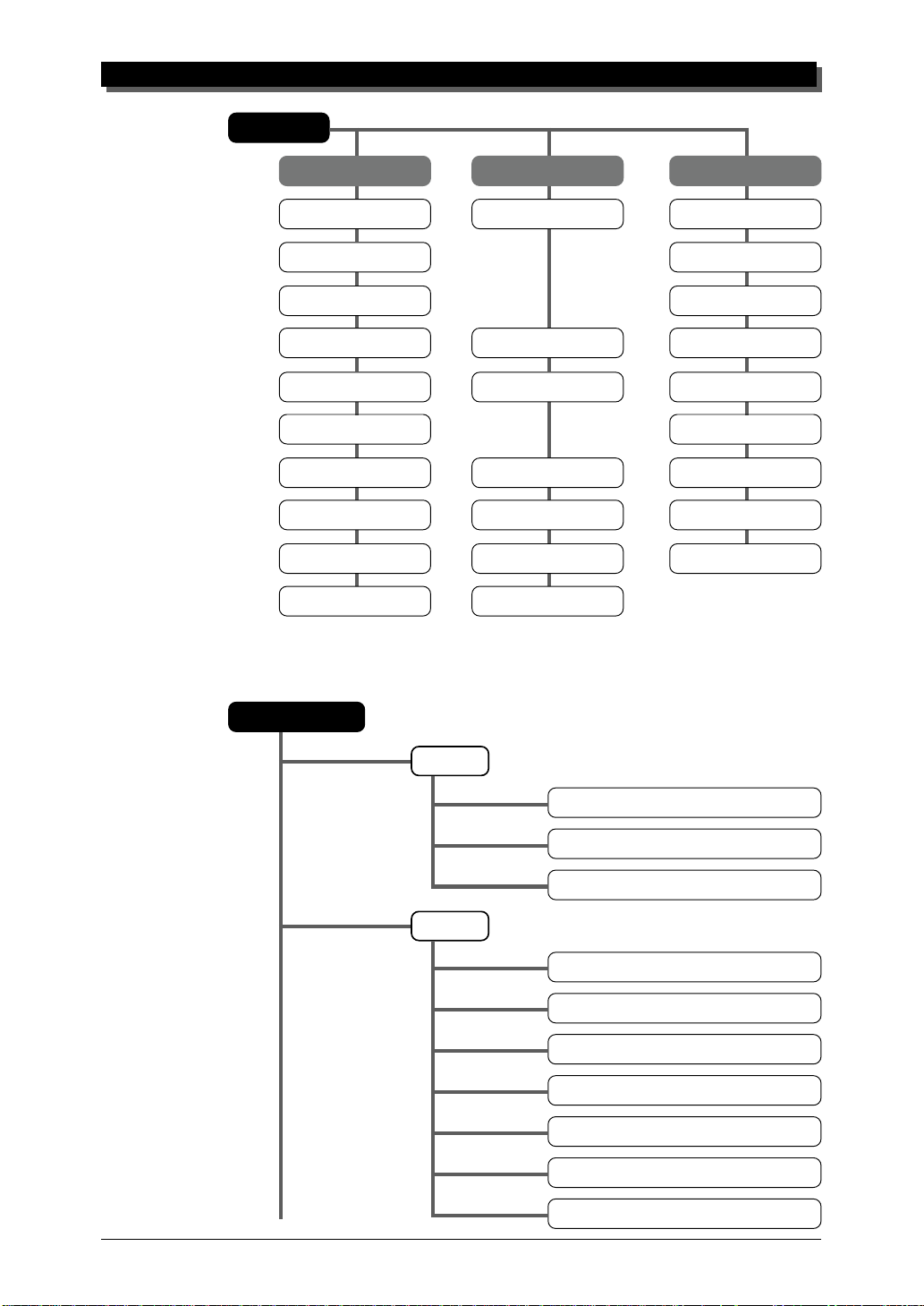
Play Mode
Part 1 … 32 A ll Part A/D
Receive Channel Device Number Receive Channel
Bank Number Source Variation
Program Number A/D Source
Volume Master Volume Volume
Expression Master Attenuator Expression
Pan Pan
Reverb Send Reverb Return Reverb Send
Chorus Send Chorus Return Chorus Send
Variation Send Variation Return Variation Send
Note Shift Transpose
The MU90R has several different Edit modes, each with various menus and
operations:
Part Edit Mode
Filter
LPF Cutoff Frequency
LPF Resonance
HPF Cutoff Frequency
EG
EG Attack Time
EG Decay Time
EG Release Time
Pitch EG Initial Level
Pitch EG Attack Time
Pitch EG Release Level
Pitch EG Release Time
7
Page 17
THE MU90R — WHAT IT IS AND WHAT IT CAN DO
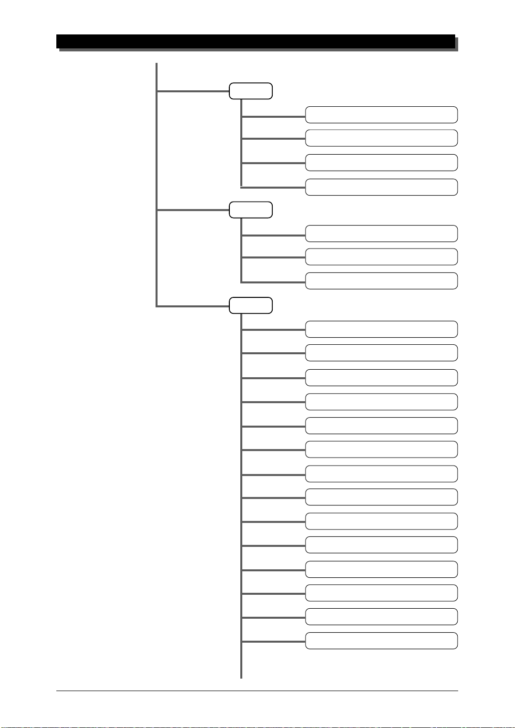
EQ
Vibrato
Others
EQ Low Frequency
EQ Low Gain
EQ High Frequency
EQ High Gain
Vibrato Rate
Vibrato Depth
Vibrato Delay
Detune
Part Mode
Mono/Poly Mode
Portamento Switch
Portamento Time
Element Reserve
Note Limit Low
Note Limit High
Dry Level (VarConnect=SYS)
Velocity Sensitivity Depth
Velocity Sensitivity Offset
Velocity Limit Low
Velocity Limit High
Pitch Bend Control
8
Page 18
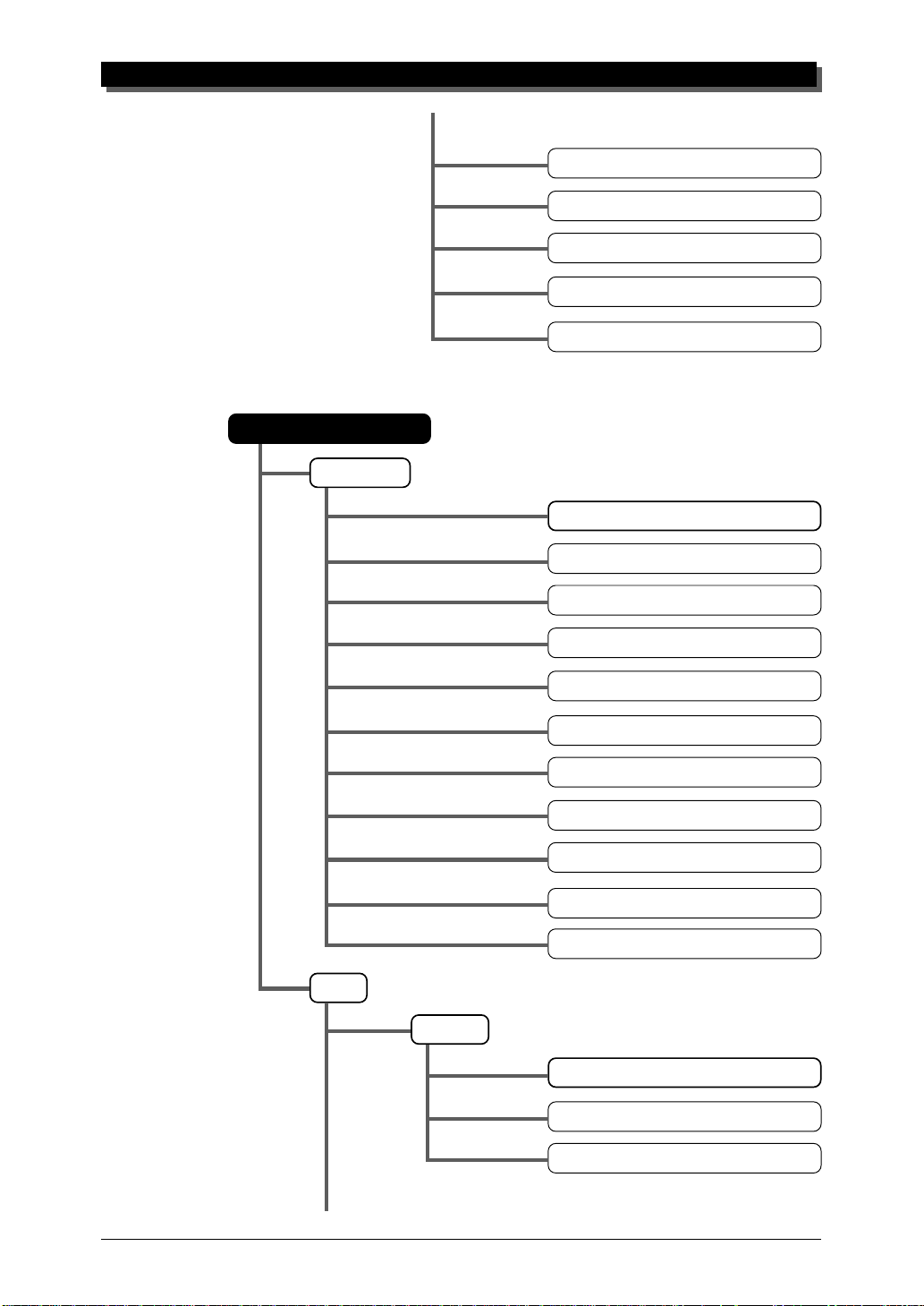
Performance Edit Mode
Common
THE MU90R — WHAT IT IS AND WHAT IT CAN DO
MW LFO Pitch Modulation Depth
AC1 Control Change Number
AC1 Filter Control
AC1 Amplitude Control
Output Select
Performance Name
Portamento Switch
Part
Portamento Time
MW LFO Pitch Modulation Depth
MW LFO Filter Modulation Depth
Pitch Bend Control
A/D Part
AC1 Control Change Number
AC1 Filter Control
AC1 Amplitude Control
AC1 LFO Filter Modulation Depth
Filter
LPF Cutoff Frequency
LPF Resonance
HPF Cutoff Frequency
9
Page 19
THE MU90R — WHAT IT IS AND WHAT IT CAN DO
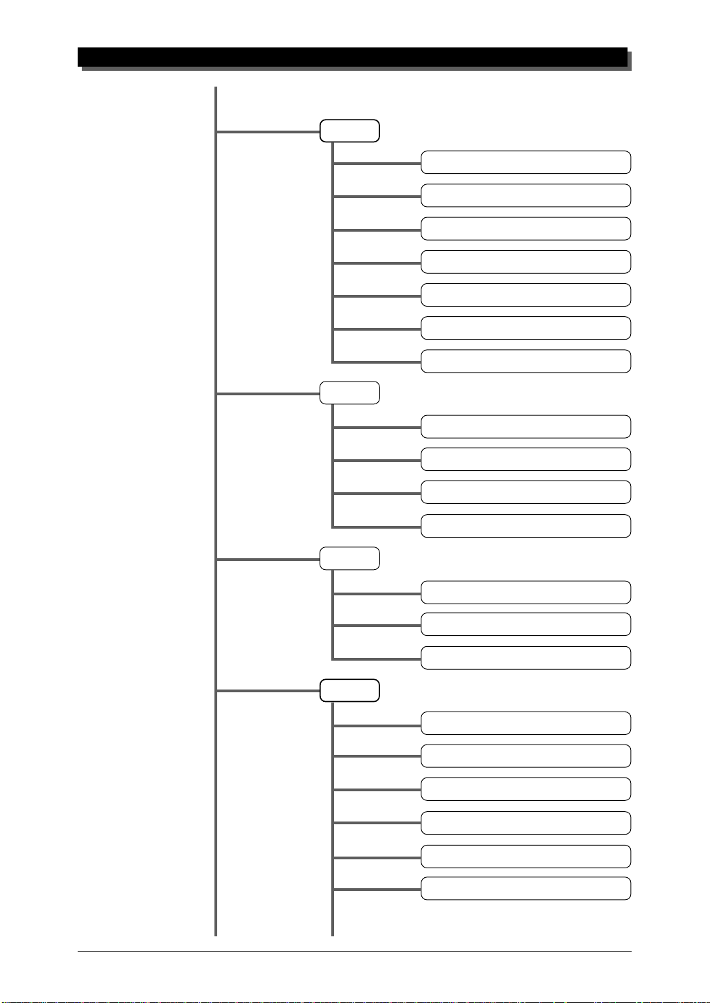
EG
EQ
EG Attack Time
EG Decay Time
EG Release Time
Pitch EG Initial Level
Pitch EG Attack Time
Pitch EG Release Level
Pitch EG Release Time
EQ Low Frequency
Vibrato
Others
EQ Low Gain
EQ High Frequency
EQ High Gain
Vibrato Rate
Vibrato Depth
Vibrato Delay
Detune
Mono/Poly Mode
Note Limit Low
Note Limit High
Dry Level (VarConnect=SYS)
10
Velocity Sensitivity Depth
Page 20
For more information on each of these modes and their menus, see the respective sections in the Reference section.
Utility Mode
The Utility mode lets you set functions related to the overall operation of
the MU90R, such as Master Tune, display Contrast and reception of certain MIDI messages that affect the entire instrument. Included also are miscellaneous operations, such as sending bulk data to a data storage device,
initializing of the MU90R settings, and playing the special Demo song.
THE MU90R — WHAT IT IS AND WHAT IT CAN DO
Velocity Sensitivity Offset
Velocity Limit Low
Velocity Limit High
Copy
Store
Recall
Part Edit Mode
The Part Edit mode allows you to change certain settings for each individual Part, such as those of the Filter, EG (Envelope Generator), and many
other settings. The internal Voices can be sounded during editing, allowing
you to hear the effects of your edits.
11
Page 21

THE MU90R — WHAT IT IS AND WHAT IT CAN DO
MEMO
12
Page 22

G
When using your MU90R for the first time, read through this
short section of the manual. It guides you step-by-step in using many of the basic operations: setting the instrument up,
connecting it properly to other equipment, and — most importantly — playing it.
UIDED
T
OUR
Page 23

GUIDED TOUR
Setting Up Your MU90R
In this introductory section, you’ll learn how to set up the MU90R for use
with a MIDI keyboard. (Setting up for use with a computer is covered on
page 29.)
What You’ll Need
☛ The MU90R and the included power adaptor.
☛ A MIDI keyboard, electronic piano, or any instrument that can output
MIDI data.
☛ An amplifier/speaker system, preferably stereo. Alternately, you can use
a set of stereo headphones.
☛ Audio connecting cables.
☛ A MIDI cable.
Making the Connections
CAUTION!
Before making any connections, make sure that all equipment to be connected is turned off,
and that the MU90R power adaptor is not connected to an electrical outlet.
Operation
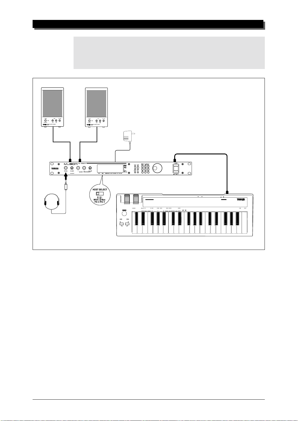
1 Connect one end of the MIDI cable to the MIDI OUT terminal of
the MIDI keyboard and the other to MIDI IN-A of the MU90R (as
shown in the illustration below).
2 Connect the audio cables from the R and L/MONO OUTPUT
jacks of the MU90R to the appropriate inputs on the amplifier
speaker system (as shown in the illustration below). You can also
connect cables to the INDIV. OUTPUT jacks.
If the amplifier has only one input, use the L/MONO jack on
the MU90R. If you are using stereo headphones, connect them
to the front panel PHONES jack.
3 Set the HOST SELECT switch on the MU90R to MIDI.
14
Connect the power adaptor to the DC IN terminal on the MU90R
4
and plug the adaptor into an appropriate electrical outlet.
Page 24
GUIDED TOUR
CAUTION!
● Do not attempt to use an AC adaptor other than the PA-3B. The use of an incompatible
adaptor may result in irreparable damage to the MU90R, and even pose a serious shock
hazard.
● Be sure to disconnect the power adaptor from the outlet when the MU90R is not in use.
PHONES
Amplifier
Speaker System
R
Power
Adaptor
DC INL/MONO
OCTAVE SHIFT
MIDI IN-A
MIDI CABLE
MIDI OUT
DC IN
CONTROLLER NUMBER LIST
CONTROL CHANGE
1 MODULATION DEPTH
2 BREATH CONTROL
4 FOOT CONTROL
5 PORTAMENTO TIME
6 DATA ENTRY
7 MAIN VOLUME
ASSIGNABLE
STOP CONTINUE START
8 BALANCE CONTROL
10 PANPOT
PROGRAM RESET SYSTEM WHEEL ASSIGNSEQUENCER
PROGRAM
GMONXG
BANK
CHANGE
TEMPO
SELECT
PITCH
SHIFT
OCTAVE
OCTAVE
RESET
73 ATTACK TIME
11 EXPRESSION
74 BRIGHTNESS
64 HOLD1(DAMPER)
84 PORTAMENTO CONTROL
65 PORTAMENTO
91 REVERB DEPTH
66 SOSTENUTO(CHORD HOLD)
92 TREMOLO DEPTH
67 SOFT PEDAL
93 CHORUS DEPTH
69 HOLD2 (FREEZE)
94 VARIATION DEPTH
71 HARMONIC CONTENT
95 PHASER DEPTH
72 RELEASE TIME
MIDI
SOUND
MERGE
FIXED
DRUM
CONTROLLER
NRPN
RPN
CH
ON
OFF
ON/OFF 1 2 3 4 5 6 7 8 9 A B C D E F 0
VELOCITY
NUMBER
(RPN)
120 PITCH BEND SENSITIVITY
121 FINE TUNING
122 COARSE TUNING
(NRPN)
123 VIBRATO RATE
124 VIBRATO DEPTH
125 VIBRATO DELAY
TRANSPOSE
IN MIDI OUT
126 FILTER CUTOFF FREQUENCY
127 FILTER RESONANCE
128 EG ATTACK TIME
129 EG DECAY TIME
130 EG RELEASE TIME
131 DRUM FILTER CUTOFF FREQUENCY
132 DRUM FILTER RESONANCE
133 DRUM EG ATTACK RATE
134 DRUM EG DECAY RATE
135 DRUM PITCH COARSE
136 DRUM PITCH FINE
137 DRUM LEVEL
138 DRUM PAN
139 DRUM REVERB DEPTH
140 DRUM CHORUS DEPTH
141 DRUM VARIATION DEPTH
POWER ON OFF
OTHERS
142 CHANNEL PRESSURE
143 POLYPHONIC KEY PRESSURE
144 MASTER VOLUME
145 MASTER BALANCE
146 MASTER TUNING
147 VELOCITY
148 TEMPO
MIDI KEYBOARD CBX-K1
HEXA
DECIMAL
ENTER
DECIMAL
MIDI Keyboard
15
Page 25
GUIDED TOUR
Powering Up and Playing the Demo Song
Once you’ve connected everything properly, you’re ready to turn the
MU90R on and start playing it. However, a small word of caution before
you begin: Follow the instructions given below to avoid possible damage
to your equipment and speakers.
Powering Up
Operation
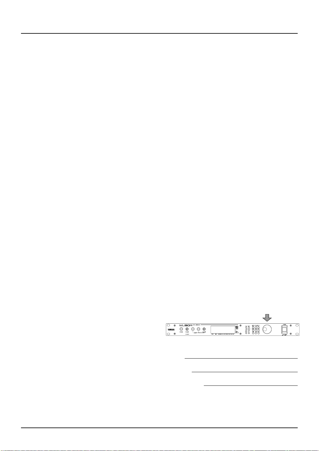
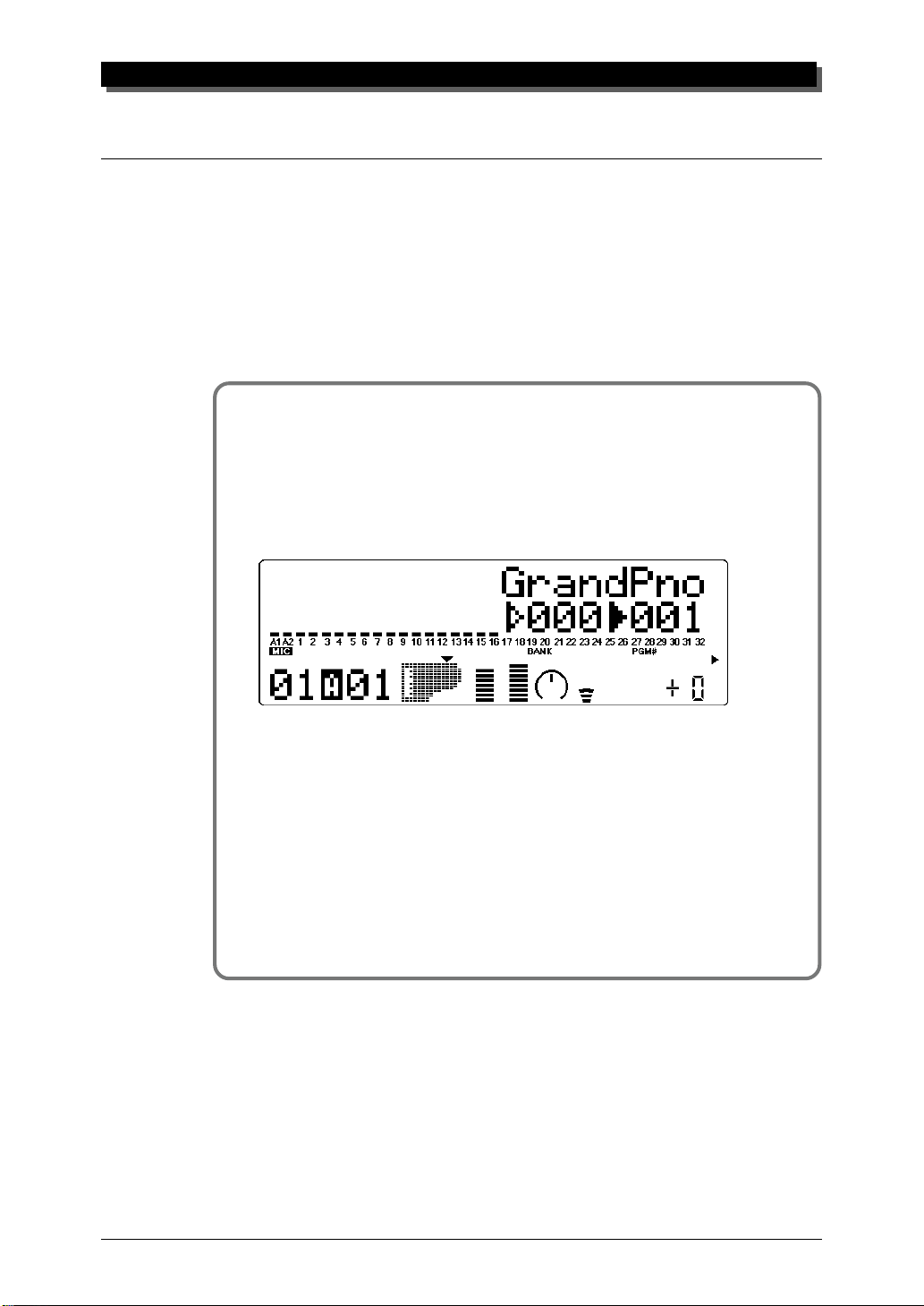
1 If you haven’t done so already, press the POWER switch on the
MU90R.
After the greeting display, the following display will appear:
16
2 Turn on the power of your MIDI keyboard.
3 Make sure that all volume controls (on the MU90R and the con-
nected amplifier) are turned down. Then, turn on the power of
your amplifier speaker system.
4 Finally, set the volume control on the MU90R to about the mid-
way position and set the volume on the amplifier to a suitable
level.
Page 26

Playing the Demo Song
Now that you’ve set everything up properly, try playing the built-in Demo
Song. This showcases the high-quality Voices and the AWM2 tone generation system of the MU90R.
Operation
1 Press the UTIL button.
2 Select “DEMO” with the SELECT w buttons and press the
ENTER button.
GUIDED TOUR
3 Press the ENTER button to start the Demo Song.
The Demo Song starts playing immediately and repeats indefinitely
until stopped (in step 4 below). After a while, playback of the individual Parts of the song is shown graphically by the “level meter” bars
in the display.
NOTE
During Demo Song playback, all panel controls (except the EXIT button and the VOLUME
control) cannot be used.
4 To stop playback of the song, press the EXIT button.
5 To exit from the Demo Song function, press the EXIT button
again.
17
Page 27

GUIDED TOUR
Playing Your MU90R With a MIDI Keyboard
Operation
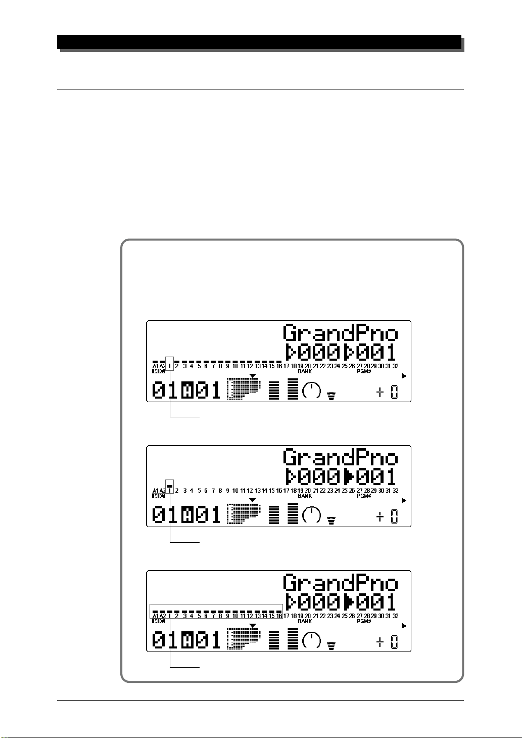
Play some notes on your MIDI keyboard.
If you’ve carefully followed all instructions up to now, one of
the “level meter” bars in the display should move — and you
should be able to hear the sound of the MU90R as you play.
The “level meter” bar indicates the “level” (velocity) of the
incoming MIDI data.
The number under the moving “level meter” indicates the Part number.
NOTE
If your MIDI keyboard is transmitting on channel 1, the Voice of Part 1 should sound. If it is
transmitting on another channel, another Part’s Voice will sound. For the sake of these introductory instructions, set your keyboard so that it transmits on channel 1. (Refer to the owner’s manual of that instrument if necessary.)
18
Page 28

Selecting Voices
In this brief section, you’ll learn how to select other Voices. You can do
this directly from the panel of the MU90R or remotely, from your MIDI
keyboard.
Operation
1 First, select a Part. Use the PA R T q buttons to select Part 1.
Press the appropriate button until “01” appears in the PART section of the display.
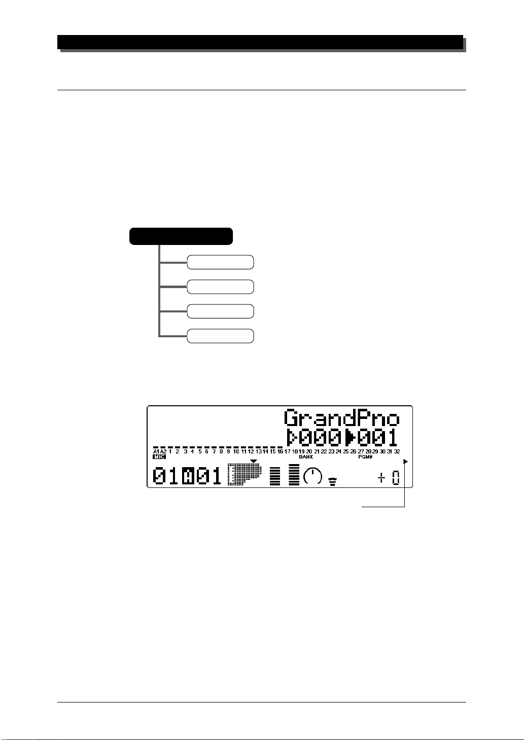
GUIDED TOUR
2 Use the SELECT w buttons to move the arrow cursor to the
right side of the instrument icon, as shown below.
Solid arrow at Voice number (currently selected).
Arrow cursor (indicates currently selected control).
The arrow is directly above “PGM#” on the panel,
Voice name.
Instrument icon of current Voice.
MIDI receive channel for current Part.
Part number. (This is selectable only with the PAR T q buttons.)
indicating that Program Number is currently selected.
Voice number (program number).
3 Use the VALUE q buttons or data dial to change the Voice
number. In the display below, Voice number 26 has been selected.
Use these to move arrow cursor.
19
Page 29

GUIDED TOUR
Play this new Voice from the keyboard. Try selecting other Voices
and play them as well. (For a list of all the available Voices, refer to
the SOUND LIST & MIDI DATA booklet.
HINT
You can rapidly move through the values by holding down one of the VALUE q buttons.
You can move even more rapidly by holding down one button and then pressing and holding down the other. For example, to rapidly advance (increase) the value, hold down the
VALUE + button and simultaneously press and hold down the VALUE – button.
Changing the Voice Bank
In the current Sound Module mode (XG), several banks of Voices are
available. Each bank can contain up to 128 different Voices.
Operation
1 Use the SELECT w buttons to move the arrow cursor to the
left side of the instrument icon, as shown below.
Solid arrow at Bank number (currently selected).
Bank number.
Arrow cursor (indicates currently selected control).
The arrow is directly above “BANK” on the panel,
indicating that Bank number is currently selected.
Use these to move arrow cursor.
20
Page 30

2 Use the VALUE q buttons or data dial to change the Bank
number.
3 Finally, use the SELECT w buttons again to move the arrow
cursor back to the right side of the instrument icon — for Voice
selection.
Selecting Voices From Your MIDI Keyboard
GUIDED TOUR
You can also select Voices remotely from the connected MIDI keyboard. Though the actual operation may differ depending on the
keyboard used, the general procedure is the same. (Refer to the
owner’s manual of your instrument for specific instructions.)
Operation
1 Make sure that your keyboard is set up to send Program Change
messages.
2 Use the panel controls to select a program on your keyboard.
Generally, if everything has been set up properly, the Voice number
and name on the MU90R will change, and will be the same number
as the program number you selected on your keyboard.
21
Page 31

GUIDED TOUR
Changing Some of the Settings — Part Controls
You can make changes to each individual Part by using the Part controls.
These are always displayed in the Play mode, giving you at-a-glance confirmation of the various basic settings of the MU90R. Let’s take a look at
the Play display again:
Voice name, bank number and program number
for the selected Part.
PART MIDI
Part number.
BANK/PGM# VOL EXP PAN REV CHO VAR KEY
Note Shift setting
for the selected
Part.
Variation Send setting
for the selected Part.
Chorus Send setting for the
selected Part.
Pan setting for the selected Part.
Expression setting for the selected Part.
Volume setting for the selected Part.
MIDI receive channel for the selected Part.
Each of these settings can be made independently for each of the Parts. For
example, each Part could have a different Volume setting, or a different Pan
setting. Try going through the brief sections below and making some
changes in the Part controls yourself.
Selecting Another Part and Changing its MIDI Channel
Here we’ll select Part 2 and change its MIDI channel to 1, so that it
matches the MIDI channel of Part 1. This allows you to play the Voices of
both Part 1 and Part 2 over MIDI channel 1.
22
Page 32

GUIDED TOUR
Operation
1 Use the PA RT q buttons to select Part 2.
Part 2.
2 Use the SELECT w buttons to call up the “Rcv CH” display
below.
Current MIDI Receive Channel.
3 Use the VALUE q buttons or data dial to change the MIDI
Receive Channel to “A01.”
4 Finally, use the SELECT w buttons to move the arrow cursor
back to the instrument icon (so that the Voice name is displayed),
and play the MIDI keyboard again.
Both “level meters” move together.
If both Parts 1 and 2 have been set to MIDI channel 1, both of their “level
meters” should move together as you play. And, if the two Parts are set to different Voices, you should hear two different Voices sound at the same time.
(T o change the Voice for a Part, refer back to Selecting V oices above.)
23
Page 33

GUIDED TOUR
Changing the Volume and Pan Settings of a Part
Now that you’re playing two Voices at the same time, you may want to adjust their settings. Here, we’ll change the Volume and Pan settings of one
Part’s Voice.
Operation
Use the PART q buttons to select the desired Part (Part 1 or 2).
1
2 Use the SELECT w buttons to call up the “Volume” display
below.
Current Volume setting.
3 Use the VA L UE q buttons or data dial to change the setting,
and play the keyboard as you make changes.
4 Now that you’ve adjusted the Volume balance of the two Voices,
change one of the Part’s Pan setting. Use the SELECT w buttons to call up the “Pan” display below.
Current Pan setting.
5 Use the VA L UE q buttons or data dial to change the setting,
and play the keyboard again as you make changes.
If you want, try making changes to some of the other Part controls. The
procedure is the same: 1) Use the PART q buttons to select a Part, 2)
use the SELECT w buttons to choose the desired control, and 3) use
the VALUE q buttons or data dial to change the setting. For more
information on the Part controls, see page 40.
24
Page 34
Using Mute/Solo
The MU90R has convenient Mute and Solo functions for selectively muting or soloing any of the 32 Parts and A/D Parts A1 and A2. This is especially useful when playing back several Parts from a connected computer
or sequencer. Mute lets you silence one Part to hear how all of the other
Parts sound without it. Solo lets you isolate a single Part, to hear how that
Part sounds by itself.
Mute and Solo are effective tools that help you as you edit the Parts,
since they allow you to better hear how the changes you make affect specific Voices as well as the overall sound.
Operation
While playing the keyboard (or during playback of a song from a
sequencer), press the MUTE button. Each press cycles through the
three functions: Mute, Solo and Normal operation.
GUIDED TOUR
The selected Part is muted, while all other Parts sound normally.
The selected Part is soloed, while all other Parts are muted.
All Parts sound normally.
25
Page 35

GUIDED TOUR
Using the A/D Input
The MU90R features a special A/D (Analog-to-Digital) Input function that
allows you to connect a microphone, electric guitar or other instrument and
mix in those signals with the MU90R’s Voices. A/D Input is perfect for
singing along with your keyboard performance, since it allows you to blend
the two signals without the need for an external mixer. Or you can use it to
sing or play guitar over backing tracks played from a MIDI sequencer.
There are two A/D Parts — A1 and A2 — and they include several different pre-programmed settings that take advantage of the built-in effects of
the MU90R.
The MU90R has two inputs on the front panel. The signals from these
are mixed.
Operation
1 Turn down the A/D INPUT control on the front panel.
26
2 Connect the microphone, instrument or audio source to the A/D
INPUT jack(s) on the front panel. (Depending on the equipment
you intend to connect, converting adaptors may be necessary.)
Page 36

GUIDED TOUR
3 Use the PA RT q buttons to select Part A1.
4 Use the SELECT w buttons to move the arrow cursor to
PGM#, as shown below, and use the VALUE q buttons or
data dial to select number 002.
5 Move the arrow cursor to BANK (with the SELECT w buttons)
and use the VALUE q buttons or data dial to select the type
of input: Mic, Guitar, Keyboard, Audio, Stereo Keyboard or
Stereo Audio. This determines the gain level of the input. Select
the type corresponding to the input you’ll use.
6 Slowly bring up the A/D INPUT control on the front panel and
play the instrument (or sing into the microphone) until the level
is appropriate.
27
Page 37

GUIDED TOUR
7 Now, move the arrow cursor back to PGM# (with the SELECT
w buttons) and try selecting some different A/D programs
(with the VALUE q buttons or data dial).
The available programs have been specially programmed to suit
the type of input selected. For example, programs for Mic input
include Karaoke and Vocal; Guitar input programs include Tube,
Stack and Phaser. Explore some of these settings on your own
with a microphone and different instruments.
28
Page 38

GUIDED TOUR
Setting Up the MU90R in Your Music System
As you learned in the section The MU90R — What It Is and What It
Can Do on page 4, the MU90R can be integrated into a variety of setups. It
would be impossible to cover all connection possibilities in a short manual
as this; however, the section below will help in quickly setting up the
MU90R and using it in your system.
Connecting With a Computer
The MU90R features a built-in host computer interface, allowing you to directly connect it to your computer — eliminating the need of installing a
special MIDI interface to your computer. The MU90R can be used with the
following computers: Apple Macintosh and IBM PC.
If your computer has a MIDI interface you may want to connect the
MU90R to it, rather than using the host computer interface on the MU90R.
(See the section “Connecting to Other MIDI Devices” on page 31.)
Depending on the computer or interface used, set the HOST SELECT
switch to the appropriate setting: MIDI, PC-1, PC-2 (IBM and clones), or
Mac (Macintosh). For information on the types of cables that can be used
for connection, see the section “MIDI/Computer Connecting Cables” on
page 35.
Macintosh
Follow these instructions if you have an Apple Macintosh not equipped
with an external MIDI interface. Connect the TO HOST terminal on the
MU90R to the Modem or Printer port on the Macintosh.
Modem or
Printer Port
Macintosh
29
Page 39

GUIDED TOUR
Operation
1 Set the HOST SELECT switch to Mac.
2 Connect the MU90R to the host computer, as shown in the illus-
tration above. Use a standard Macintosh cable (8-pin Mini DIN
on both ends; see page 35).
3 Turn on the the host computer, then the MU90R.
4 Start up your music software, and set up the appropriate options
on the software for operation with the MU90R.
The options you may have to set include:
gg
g
MIDI Interface Type
MIDI Time Piece
Clock
Standard MIDI Interface
gg
gg
g
On (for controlling all 32 Parts of the MU90R)
gg
gg
g
1 MHz
gg
Other options and settings may have to be made as well. Refer to the owner’s manual of your particular music software for more information.
IBM PC /AT and Clones
Follow these instructions if you have an IBM PC/AT or compatible computer
not equipped with an external MIDI interface. Connect the TO HOST terminal on the MU90R to one of the computer’s serial ports, COM 1 or COM 2.
Serial Port
IBM PC/AT or Compatible Computer
NOTE
Your music software must be able to recognize the TO HOST connection. Consult your
Yamaha dealer for more details. If your software is not compatible, you can still use the
MU90R by installing a MIDI interface (internal card or external) to the computer.
30
Page 40

Operation
1 Set the HOST SELECT switch to PC-2.
2 Connect the MU90R to the host computer, as shown in the illus-
tration above. Use a standard computer cable (8-pin Mini DIN
to 9-pin D-SUB; see page 35).
3 Turn on the the host computer, then the MU90R.
4 Start up your music software, and set up the appropriate options
on the software for operation with the MU90R.
Refer to the owner’s manual of your particular music software for more information.
Connecting to Other MIDI Devices
GUIDED TOUR
The MU90R is equipped with MIDI IN and OUT terminals, allowing you to
use it in any MIDI system. Example uses for the built-in MIDI interface include:
☛ Connecting to a MIDI keyboard (for playing the sounds of the MU90R
from that keyboard).
☛ Connecting to a computer equipped with a MIDI interface (either in-
ternal or external).
☛ Connecting to a hardware sequencer (such as the Yamaha QY700).
☛ Connecting to a MIDI data storage device (such as the Yamaha MDF2
MIDI Data Filer).
31
Page 41

GUIDED TOUR
MIDI CABLE
MIDI OUT
OCTAVE SHIFT
MDF2
MIDI IN-A or IN-B
MIDI CABLE
MIDI OUT
DC IN
IN MIDI OUT
CONTROLLER NUMBER LIST
CONTROL CHANGE
11 EXPRESSION
73 ATTACK TIME
(RPN)
1 MODULATION DEPTH
64 HOLD1(DAMPER)
2 BREATH CONTROL
4 FOOT CONTROL
5 PORTAMENTO TIME
6 DATA ENTRY
7 MAIN VOLUME
8 BALANCE CONTROL
PITCH
ASSIGNABLE
10 PANPOT
PROGRAM RESET SYSTEM WHEEL ASSIGNSEQUENCER
PROGRAM
BANK
CHANGE
STOP CONTINUE START
TEMPO
SHIFT
OCTAVE
OCTAVE
RESET
SELECT
74 BRIGHTNESS
65 PORTAMENTO
84 PORTAMENTO CONTROL
66 SOSTENUTO(CHORD HOLD)
91 REVERB DEPTH
67 SOFT PEDAL
92 TREMOLO DEPTH
69 HOLD2 (FREEZE)
93 CHORUS DEPTH
71 HARMONIC CONTENT
94 VARIATION DEPTH
72 RELEASE TIME
95 PHASER DEPTH
MIDI
GMONXG
SOUND
MERGE
FIXED
CONTROLLER
RPN
CH
ON
OFF
ON/OFF 1 2 3 4 5 6 7 8 9 A B C D E F 0
VELOCITY
126 FILTER CUTOFF FREQUENCY
120 PITCH BEND SENSITIVITY
127 FILTER RESONANCE
121 FINE TUNING
128 EG ATTACK TIME
122 COARSE TUNING
129 EG DECAY TIME
(NRPN)
130 EG RELEASE TIME
123 VIBRATO RATE
131 DRUM FILTER CUTOFF FREQUENCY
124 VIBRATO DEPTH
132 DRUM FILTER RESONANCE
125 VIBRATO DELAY
133 DRUM EG ATTACK RATE
TRANSPOSE
DRUM
NRPN
NUMBER
134 DRUM EG DECAY RATE
135 DRUM PITCH COARSE
136 DRUM PITCH FINE
137 DRUM LEVEL
138 DRUM PAN
139 DRUM REVERB DEPTH
140 DRUM CHORUS DEPTH
141 DRUM VARIATION DEPTH
POWER ON OFF
OTHERS
142 CHANNEL PRESSURE
143 POLYPHONIC KEY PRESSURE
144 MASTER VOLUME
145 MASTER BALANCE
146 MASTER TUNING
147 VELOCITY
148 TEMPO
MIDI KEYBOARD CBX-K1
ENTER
HEXA
DECIMAL
DECIMAL
MIDI Keyboard
MIDI IN-B
32
Operation
1 Set the HOST SELECT switch to MIDI.
2 Connect the MU90R to the appropriate MIDI device, as shown
in the illustrations above. Use a standard MIDI cable (see page
35).
3 Turn on the the connected device, then the MU90R.
4 If you are using a computer, start up your music software, and
set up the appropriate options on the software for operation with
the MU90R.
Page 42

GUIDED TOUR
Using the MU90R with a MIDI Data Storage Device
You can also use the MU90R with a MIDI data storage device, such as the
Yamaha MDF2 MIDI Data Filer. This lets you save or back up whatever
changes you’ve made in the settings of the Utility and Part Edit modes, as
well as changes to the EQ built-in effects and Performances. Then, when
you want to recall those settings, you can transfer the appropriate data from
the storage device.
The MDF2 also allows you to play compatible song data on the
MU90R directly from the MDF2 itself, without the need of a sequencer.
Make sure that the MU90R is properly connected to the data storage
device (via MIDI). Use the Dump Out function (page 119) to send data to
the device. Also refer to the owner’s manual of your data storage device
for specific operating instructions in receiving or sending data.
MIDI CABLE
MIDI IN
MDF2
MIDI OUT
33
Page 43

GUIDED TOUR
Data Flow Block Diagram
When HOST SELECT switch is set to MIDI (31,250 bps):
TO HOST IN-B IN-A OUT THRU
Sound
Module
A1~16CH
Sound
Module
B1~16CH
When HOST SELECT switch is set to
PC-1/MAC (31,250 bps) or PC-2 (38,400 bps):
TO HOST IN-B IN-A OUT THRU
Sound
Module
A1~16CH
Sound
Module
B1~16CH
34
Page 44

MIDI/Computer Connecting Cables
MIDI
Standard MIDI cable. Maximum length 15 meters.
GUIDED TOUR
DIN 5-PIN DIN 5-PIN
4
2
5
4
2 (GND)
5
Mac
Apple Macintosh Peripheral cable (M0197). Maximum length 2 meters.
MINI DIN
8-PIN
1
2
3
4 4 (GND)
5 3 (TxD –)
6 8 (RxD +)
7 7 (GP i)
8 6 (TxD +)
2 (HSK i)
1 (HSK o)
5 (RxD –)
MINI DIN
8-PIN
PC-1
8-pin MINI DIN to D-SUB 25-pin cable. If your PC-1 type computer has a
9-pin serial port, use the PC-2 type cable. Maximum length 1.8 meters.
MINI DIN
8-PIN
1
2
3
4 7 (GND)
8
5 2 (TxD)
5 (CTS)
4 (RTS)
3 (RxD)
D-SUB
25-PIN
PC-2
8-pin MINI DIN to D-SUB 9-pin cable. Maximum length 1.8 meters.
MINI DIN
8-PIN
1
2
3
4 5 (GND)
8
5 3 (TxD)
This concludes your basic tour of the important functions of the MU90R. To find out
more about how to best use your MU90R, look through the Reference section that follows and try out some of the functions and operations that interest you.
8 (CTS)
7 (RTS)
2 (RxD)
D-SUB
9-PIN
35
Page 45

MEMO
Page 46

R
The Reference section of this manual covers in detail all of
the functions of the MU90R. Refer to it when you need information about a specific function, feature or operation.
EFERENCE
Page 47

MULTI MODE
Multi Mode
In the Multi mode, the MU90R performs as a multi-timbral tone generator
capable of playing up to 32 Parts simultaneously, over 32 MIDI channels.
Normally, the MU90R should be set to Multi mode when using it with a
sequencer and General MIDI song data. There are three Multi modes: XG,
TG300B and C/M. Each mode provides compatibility with different music software and hardware.
XG: This stands for Extended General MIDI and provides the full poten-
tial of the MU90R, giving you access to all 586 Voices.
TG300B: This mode provides compatibility with the GM-B mode of the TG300
Tone Generator.
C/M: This mode provides compatibility with most computer music soft-
ware not supported by the other two Multi modes.
NOTE
When set to the TG300B mode, the MU90R may not be able to play TG300-specific song data with complete
accuracy. However, MIDI data designed for other computer music tone generators is compatible with the
MU90R.
To set the Multi mode:
1 Press the MODE button.
2 Use theg SELECT w buttons to select the desired Multi mode:
XG, TG300B or C/M.
3 Press the EXIT button or the PLAY button to return to the Play
display.
XG
TG300B
C/M
PERFORMANCE
Indicates currently selected mode.
38
The currently selected mode setting is shown by the arrow at the bottom
right of the display.
Page 48

Multi Play Mode
The Play mode (with the main Play display shown below) is the normal
operating mode of the MU90R. To select the Play mode from any other
mode, press the PLAY button. (The Play mode is also automatically se-
lected when you turn on the MU90R.)
MULTI MODE
Current Part number.
NOTE
Applications that are capable of controlling 32 Parts (e.g., Performer) are set to a clock rate of
1 MHz.
Play Displays
The Play mode has three basic displays, that can be changed according to
your preference. Simply press the PLAY button repeatedly, and the display
alternates as shown below:
Velocity “level meters” for each Part.
MIDI port (A or B) and channel number for currently selected Part.
Voice number and name for
currently selected Part.
1)
Shows full “level meter” indication for the A1 and A2 A/D Parts and Parts
1 — 16. Currently selected parameter (here, Voice number and name) is
displayed at the right side.
39
Page 49

MULTI MODE
Parts 17 — 32 can be displayed by selecting one of those Parts with the
PART q buttons. For example, when Part 18 is selected, the changes
as shown below:
2)
Shows half “level meter” indication for the A1 and A2 A/D Parts and all 32
Parts. Currently selected parameter (here, Voice number and name) is displayed at top.
3)
Shows full “level meter” indication for the A1 and A2 A/D Parts and all 32
Parts. Currently selected parameter is not displayed.
Part Controls
The Part controls in the Play mode give you tools for adjusting the basic
sound and settings for each Part. The MU90R lets you adjust the various
settings for each Part individually (Single Part control) or together (All Part
control). Each of these types is explained in greater detail below.
NOTE
In the Multi mode, no settings can be permanently saved to the internal memory of the
MU90R. However, you can use the Dump Out function to save Multi settings to a MIDI data
storage device. (See page 119.)
40
Page 50

Single Part Control
The Single Part controls include: MIDI Receive Channel, Bank Number,
Program Number, Volume, Expression, Pan, Reverb Send, Chorus Send,
Variation Send and Note Shift.
Selecting Single Part Control
Single Part control is automatically called up when the MU90R is turned
on. If All Part is selected, simply press both PART q buttons simulta-
neously (or press the EXIT button) to return to Single Part.
MULTI MODE
Editing in Single Part
Operation
1 Select the Part to be edited by using the PART q buttons.
2 Select the desired control for the selected Part by using the
SELECT w buttons.
3 Change the value of the selected control by using the VALUE
q buttons or data dial.
MIDI Receive Port/Channel
This determines the MIDI IN port (A or B) and the receive channel (1
— 16) for the selected Part.
Graphically indicates current Receive Channel setting.
Settings: A1 — A16, B1 — B16
41
Page 51

MULTI MODE
Bank Number
This determines the bank number of the selected Part’s Voice. Each
bank contains 128 Voices. (Refer to the SOUND LIST & MIDI DATA
booklet.)
A1/A2 (A/D Input) part:
000 — 003
Normal part:
XG: 000, 001, 003, 006, 008, 012, 014, 016 — 020, 024 —
028, 032 — 043, 045, 064 — 072, 096 — 101, SFX
TG300B: 000 — 011, 016 — 019, 024 — 026, 032, 033, 040, 080,
126, 127
C/M: Fixed (only one bank)
Drum part:
XG: 126, 127
TG300B: 000
C/M: Fixed (only one bank)
For more information on selecting banks, see Display Bank Select
parameter, page 118.
Program (Voice) Number
This determines the Voice for the selected Part. (Refer to the SOUND
LIST & MIDI DATA booklet.)
Range: 001 — 128
42
Page 52

MULTI MODE
Volume
This determines the Volume setting for the selected Part’s Voice.
Graphically indicates current Volume setting.
Range: 000 — 127
Expression (Expresn)
This determines the Expression setting for the selected Part’s Voice.
Graphically indicates current Expression setting.
Range: 000 — 127
Pan
This determines the stereo position of the selected Part’s Voice. A set-
ting of “Rnd” (Random) randomly assigns the Voice to a pan position.
This is useful when you want to have different Voices sound from dif-
ferent random parts of the stereo image. (The Random setting does not
affect the A/D input Parts.)
Graphically indicates current Pan setting.
Settings: Rnd (Random), L63 — C — R63
43
Page 53

MULTI MODE
Reverb Send (RevSend)
This determines the level of the selected Part’s Voice that is sent to the
Reverb effect. A value of 000 results in a completely “dry” Voice sound.
Graphically indicates current Reverb Send setting.
Range: 000 — 127
NOTE
Keep in mind that the Reverb effect must be properly enabled and set for this parameter to
work as intended. (See page 101.)
Chorus Send (ChoSend)
This determines the level of the selected Part’s Voice that is sent to the
Chorus effect. A value of 000 results in a completely “dry” Voice sound
(no Chorus effect).
Graphically indicates current Chorus Send setting.
Range: 000 — 127
NOTE
Keep in mind that the Chorus effect must be properly enabled and set for this parameter to
work as intended. (See page 103.)
Variation Send (VarSend)
This determines whether the selected Part’s Voice is sent to the Varia-
tion effect or not. A setting of “off” results in no Variation effect being
applied to the Voice.
44
Page 54

Graphically indicates current Variation Send setting.
Settings: off, on (when Variation Connection is set to INS);
000 — 127 (when Variation Connection is set to SYS)
Note Shift (NoteSft)
This determines the key transposition setting for the Part’s Voice.
Graphically indicates current Note Shift setting.
MULTI MODE
Range: –24 — +24 semitones
45
Page 55

MULTI MODE
All Part Control
The All Part controls include: Device Number, Master Volume, Master
Attenuator, Reverb Return, Chorus Return, Variation Return and Transpose.
Keep in mind that these controls affect all Parts equally, and either add
to or subtract from their individual values. For example, if Note Shift on
one Part is set to –12, and Transpose (in All Part) is set to +12, that Part’s
pitch value will actually be 0 or normal.
Selecting All Part Control
To select All Part control, press both PART q buttons simultaneously. (or
press the EXIT button). (“All” appears in the P ART section of the display.)
Editing in All Part
Operation
1 Select the desired control for all Parts by using the SELECT
w buttons.
2 Change the value of the selected control by using the VALUE
q buttons or data dial.
Device Number (DevNo.)
Settings: 1 — 16, all
This determines the Device Number for the MU90R, a kind of MIDI
“identification” number to distinguish between multiple units. For
Graphically indicates current Device Number setting.
46
Page 56

example, if you are using more than one MU90R, set a different Device Number for each. This is especially important when using the
data dump features. (See page 119.) If you have only one MU90R,
set this to “all.”
Master Volume (M.Volum)
Range: 000 — 127
This determines the overall Volume of the Parts.
Master Attenuator (M.Attn)
MULTI MODE
Graphically indicates current Master Volume setting.
Graphically indicates current Master Attenuator setting.
Range: 000 (maximum volume) — 127 (minimum volume)
This determines the level of all Parts, but functions as an attenuator; the
greater the value, the lower the volume. This is useful when you are
playing several songs and want to keep their overall level consistent.
Reverb Return (RevRtn)
Graphically indicates current Reverb Return setting.
Range: 000 — 127
This determines the amount of Reverb return in the overall mix.
47
Page 57

MULTI MODE
Chorus Return (ChoRtn)
Graphically indicates current Chorus Return setting.
Range: 000 — 127
This determines the amount of Chorus return in the overall mix.
Variation Return (VarRtn)
Graphically indicates current Variation Return setting.
Range: 000 — 127
This determines the amount of Variation return in the overall mix.
Variation Return is only available when the Variation Connection
parameter is set to SYS. (See page 106.)
Transpose (Trans)
Range: –24 — +24 semitones
This determines the overall Transpose setting of the Parts.
Graphically indicates current Transpose setting.
48
Page 58

Multi Edit Mode
The Multi Edit mode features various parameters for controlling the Filter,
the EG (Envelope Generator), the EQ, and Vibrato. It also features a variety of other miscellaneous controls grouped in the Others parameters.
When a Drum Part is selected, Drum-related parameters are also available.
To enter the Multi Edit mode, press the EDIT button. When a normal
Part is selected, the following menu appears:
When a Drum Part is selected, the following menu appears:
MULTI MODE
Filter
Part Edit Mode
Filter
LPF Cutoff Frequency
LPF Resonance
HPF Cutoff Frequency
The MU90R features a digital filter that can be used to change the timbre
of the Voices. The filter is affected (together with the level) by the EG (Envelope Generator), which allows you to change the timbre over time as
well. (See EG, page 52.)
49
Page 59

MULTI MODE
LPF Cutoff Frequency (LPF Cutoff)
This determines the cutoff frequency of the low pass filter (LPF). The
LPF filters out frequencies higher than the cutoff point and “passes” the
lower frequencies. Lower cutoff values create a deeper, more rounded
tone, while higher values create a brighter tone.
Graphically shows LPF Cutoff Frequency setting for each Part.
Selected Part and MIDI channel
Range: –64 — +63
Level
These frequencies are
“passed” or let through.
These frequencies are “cut”
or filtered out.
Frequency
LPF Cutoff Frequency setting
LPF Resonance (LPF Reso)
This determines the amount of filter resonance or emphasis of the LPF
Cutoff Frequency above. Higher values make the filter effect more pro-
nounced and stronger, creating a resonant peak around the cutoff fre-
quency.
Graphically shows LPF Resonance setting for each Part.
50
Selected Part and MIDI channel
Range: –64 — +63
Page 60

MULTI MODE
Level
Resonance
Frequency
LPF Cutoff Frequency setting
HPF Cutoff Frequency (HPF Cutoff)
This determines the cutoff frequency of the high pass filter (HPF). The
HPF filters out frequencies lower than the cutoff point and “passes” the
higher frequencies. Lower cutoff values preserve the fundamental and
lower overtones of the sound, while higher values create a thinner,
brighter tone.
Graphically shows HPF Cutoff Frequency setting for each Part.
Selected Part and MIDI channel
Range: –64 — +63
Level
These frequencies are
“cut” or filtered out.
These frequencies are
“passed” or let through.
Frequency
HPF Cutoff Frequency setting
51
Page 61

MULTI MODE
EG (Envelope Generator)
Part Edit Mode
EG
EG Attack Time
EG Decay Time
EG Release Time
Pitch EG Initial Level
Pitch EG Attack Time
Pitch EG Release Level
Pitch EG Release Time
The EG parameters allow you to shape the sound of a Part’s Voice — or, in
other words, set how the level and timbre of the Voice changes over time.
This section also includes independent Pitch Envelope Generator (PEG) parameters for controlling how the pitch of a Part’s Voice changes over time.
The relationship of the main EG parameters — Attack, Decay and Release — are shown in the illustration below. These parameters not only affect
the sound level, but also the timbre (with the Filter parameters; see page 49).
1) Short Attack, Decay, Release times:
Level
Attack Decay Release
Max.
Min.
Key is releasedKey is pressed
Time
52
Page 62

2) Long Attack, Decay, Release times:
Level
Attack Decay Release
Max.
MULTI MODE
Min.
Even though the key is held for the same length of time in both examples,
the sound of the second example slowly reaches full volume and decays
over a longer time. It also sustains longer after the key is released.
Keep in mind that the EG parameters affect each other, and are affected by how long a note is held. For example, if Decay is set to a
low value and the note is held for a long time, you may not be able
to hear changes made to the Release parameter.
EG Attack Time
Time
Key is releasedKey is pressed
Graphically shows EG Attack Time setting for each Part.
Selected Part and MIDI channel
Range: –64 — +63
This determines the Attack Time of the EG, or how long it takes for
the sound to reach full volume when a note is played. For the Filter,
this determines how long it takes for the sound to be affected by the
maximum Filter values.
53
Page 63

MULTI MODE
EG Decay Time
Graphically shows EG Decay Time setting for each Part.
Selected Part and MIDI channel
Range: –64 — +63
This determines the Decay Time of the EG, or how rapidly the
sound dies out as a note is held. For the Filter, this determines how
long it takes for the Filter effect to die out.
EG Release Time
Graphically shows EG Release Time setting for each Part.
54
Selected Part and MIDI channel
Range: –64 — +63
This determines the Release Time of the EG, or how long the sound
sustains after a note is released. For the Filter, this determines how
long the Filter effect continues after a note is released.
Page 64
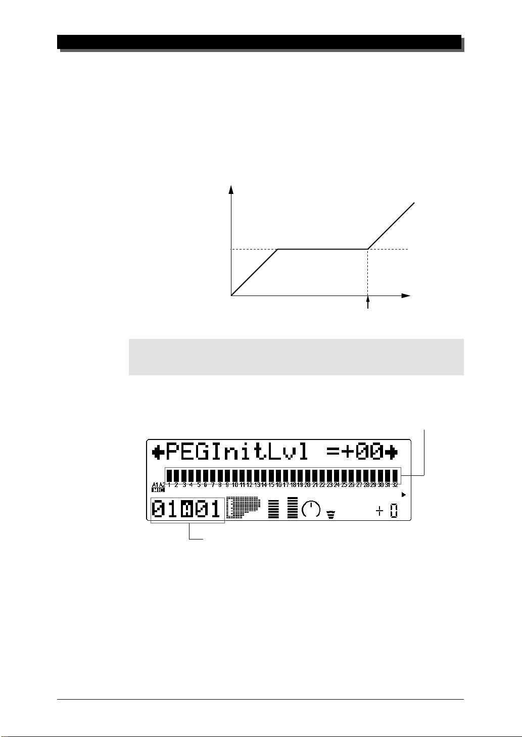
Pitch EG Parameters
The Pitch EG parameters determine how the pitch of a Part’s Voice
changes over time. This lets you produce subtle or pronounced pitch
changes as a note is played.
In the example Pitch EG settings below, a played note is gradually bent up to its normal pitch, and kept there as the note is held.
When the note is released, the pitch rapidly climbs up.
Pitch
High
Normal
MULTI MODE
Low
Key is released
NOTE
The Pitch EG parameters may have little or no effect, depending on the particular Voice used
and the settings made to the main EG parameters.
Time
Pitch EG Initial Level (PEGInitLvl)
Graphically shows Pitch EG Initial Level setting for each Part.
Selected Part and MIDI channel
Range: –64 — +63
This determines the initial pitch of the Part’s Voice, when the note is
first played. A setting of 00 corresponds to normal pitch.
55
Page 65

MULTI MODE
Pitch EG Attack Time (PEGAtakTime)
Graphically shows Pitch EG Attack Time setting for each Part.
Selected Part and MIDI channel
Range: –64 — +63
This determines the Attack Time of the Pitch EG, or how long it
takes for the pitch to return to normal (from the pitch value set in
Initial Level above).
Pitch EG Release Level (PEGReleLvel)
Graphically shows Pitch EG Release Level setting for each Part.
56
Selected Part and MIDI channel
Range: –64 — +63
This determines the final pitch of the Part’s Voice, or the pitch that
is reached after the note is released. A setting of 00 corresponds to
normal pitch.
NOTE
The Pitch EG Release Level and Time parameters may have no effect if the Voice itself does
not sustain after the note is released. (Short percussive Voices may fall into this category.)
Also make sure that the main EG Release Time is set to an appropriate value so that the sound
sustains.
Page 66

Pitch EG Release Time (PEGReleTime)
Range: –64 — +63
This determines the Release Time of the Pitch EG, or how long it
takes for the pitch to change to the pitch value set in Release Level
above.
EQ (Equalizer)
MULTI MODE
Graphically shows Pitch EG Release Time setting for each Part.
Selected Part and MIDI channel
Part Edit Mode
EQ
EQ Low Frequency
EQ Low Gain
EQ High Frequency
EQ High Gain
The EQ parameters let you adjust and set the tonal quality of a Part’s Voice,
such as boosting the bass sound, or making it brighter. This is a two-band
equalizer with wide frequency variation for each band, and is independent
of the overall EQ controls (see page 112).
57
Page 67

MULTI MODE
EQ Low Frequency (Low Freq)
This determines the frequency which is boosted or cut (in the Low Gain
parameter below) for each Part.
Graphically shows the Low Frequency setting for each Part.
Selected Part and MIDI channel
Range: 32 Hz — 2.0 kHz
EQ Low Gain
This determines the level of the selected frequency (in Low Freq
above). Positive values boost the level of the selected frequency and
negative values attenuate it.
Graphically shows the Low Gain setting for each Part.
58
Selected Part and MIDI channel
Range: –64 — +00 — +63
EQ High Frequency (High Freq)
This determines the frequency which is boosted or cut (in the High
Gain parameter below) for each Part.
Graphically shows the High Frequency setting for each Part.
Selected Part and MIDI channel
Range: 500 Hz — 16 kHz
Page 68

Vibrato
MULTI MODE
EQ High Gain
This determines the level of the selected frequency (in High Freq
above). Positive values boost the level of the selected frequency and
negative values attenuate it.
Graphically shows the High Gain setting for each Part.
Selected Part and MIDI channel
Range: –64 — +00 — +63
Part Edit Mode
Vibrato
Vibrato Rate
Vibrato Depth
Vibrato Delay
Vibrato produces a quavering, vibrating sound in the Part’s Voice, by regularly modulating the pitch. You can control the speed and depth of the Vibrato, as well as the time it takes before the Vibrato effect is applied.
Vibrato Rate
Graphically shows Vibrato Rate setting for each Part.
Selected Part and MIDI channel
59
Page 69

MULTI MODE
Range: –64 — +63
This determines the speed of the Vibrato effect. Higher values result
in a faster Vibrato sound.
Vibrato Depth
Graphically shows Vibrato Depth setting for each Part.
Selected Part and MIDI channel
Range: –64 — +63
This determines the depth of the Vibrato effect. Higher values result
in a stronger, more pronounced Vibrato sound.
Vibrato Delay
Range: –64 — +63
This determines the delay in the onset of the Vibrato effect. Delay is
effective especially on stringed instrument Voices. For example, violin players often use delayed vibrato, especially while playing long
notes. The Delay parameter is useful in recreating this effect, producing a more natural, lifelike sound. Higher values result in a
longer Delay time.
Graphically shows Vibrato Delay setting for each Part.
Selected Part and MIDI channel
60
Page 70

Others
MULTI MODE
Part Edit Mode
Others
Detune
Part Mode
Mono/Poly Mode
Portamento Switch
Portamento Time
Element Reserve
Note Limit Low
Note Limit High
Dry Level (VarConnect=SYS)
Velocity Sensitivity Depth
Velocity Sensitivity Offset
Velocity Limit Low
Velocity Limit High
Pitch Bend Control
MW LFO Pitch Modulation Depth
AC1 Control Change Number
AC1 Filter Control
AC1 Amplitude Control
Output Select
The Others section of parameters contains miscellaneous controls, including those related to tuning, Part Mode, velocity, portamento, note range,
etc.
61
Page 71

MULTI MODE
Detune
Graphically shows Detune setting for each Part.
Selected Part and MIDI channel
Range: –12.8 — +12.7
This determines the fine tuning of the Part’s Voice.
HINT
Detune could be used to slightly detune a Voice compared to the tuning of the rest of the
Voices for a richer sound. It could also be used to detune two different Voices being played
in unison. For example if two different Parts are set to the same MIDI channel (see page 41)
and same Voice, a naturally thick chorusing effect can be obtained by slightly detuning each
Voice in opposite directions here.
Part Mode
Height of bars indicates selected Part Mode setting for each Part.
Selected Part and MIDI channel
Settings: normal, drum, drumS1 — S4
(When Sound Module mode is set to C/M, both Parts 10 and 26 are set
to drumS1.)
This determines the mode for the Part. A setting of normal allows selection of the normal instrument Voices. (See the SOUND LIST & MIDI
DATA booklet.) The drum setting allows selection of the drum kits. (See
the SOUND LIST & MIDI DATA booklet.) The drumS1 — S4 settings
are locations for storing specially programmed drum setups. These setups
can be edited by using the Drum Setup controls in the Multi Edit mode.
(See page 73.) The drum and drumS1 — S4 settings are not available in
the Performance mode (all Parts are fixed to “normal”).
(A single bar indicates “normal” setting.)
62
Page 72

MULTI MODE
The Part Mode settings differ depending on the Sound Module mode
selected, as described below.
For XG (Extended General MIDI) mode:
All settings described above are available. When normal is selected,
any of the basic or the extended set of Voices can be used for the Part.
For TG300B mode:
The settings normal and drumS1 — S4 are available; drum cannot be
selected. When normal is selected, either the basic or the extended set
of Voices (for the TG300B mode) can be used for the Part.
For C/M mode:
The Part Mode settings are fixed in this mode and cannot be changed:
Parts 10 and 26 are set to drumS1, and all other Parts are set to nor-
mal. The MIDI Receive Channel setting for Parts 1 and 17 is set to off.
The 128 Voices of C/M Type 1 can be used for Parts 1 — 9 and 17 —
25; the 64 Voices of C/M Type 2 can be used for Parts 11 — 16 and 27
— 32.
For PFM (Performance) mode:
All four Parts are set to normal; none of the drum settings are available. Any of the basic or the extended set of Voices can be used for
each Part.
NOTE
When two or more different Parts are set to the same editable drum setup (drumS1 — S4),
any edits made to that drum setup automatically affect all those Parts. For example, when
two Parts are set to drumS1, any changes made to drumS1 affect both Parts.
Mono/Poly Mode
Height of bars indicates selected Mono/Poly Mode setting for each Part.
(A single bar indicates “mono” setting, while full height indicates “poly.”)
Selected Part and MIDI channel
63
Page 73

MULTI MODE
Settings: mono, poly
This determines whether the Part’s Voice is played monophonically
(only one note at a time) or polyphonically (up to 64 notes at a
time). This parameter is not available when the Part Mode is set to
Drum.
Portamento Parameters
Portamento is a function that creates a smooth pitch glide from one
note to another.
Portamento Switch (PortametSw)
This determines whether Portamento is on or off for the Part. (This parameter is not available for Drum Parts.)
Height of bars indicates selected Portamento Switch setting for each Part.
(A single bar indicates “off” setting, while full height indicates “on.”)
Selected Part and MIDI channel
Settings: off, on
Portamento Time (PortametTm)
This determines the time of the Portamento effect, or how long it takes
to glide the pitch from one note to the next. Higher values result in a
longer pitch glide time. (This parameter is not available for Drum
Parts.)
Graphically shows Portamento Time setting for each Part.
Selected Part and MIDI channel
Range: 000 — 127
64
Page 74

MULTI MODE
Element Reserve (ElemReserv)
This determines the minimum number of sound elements that are reserved for the Part. This setting ensures that when the maximum simultaneous polyphony of 64 notes (or elements) is exceeded, the selected
Part will still play up to the number of elements set here. For example,
if the Element Reserve of a Part is set to 10, the sounds for that Part
(up to 10 simultaneous notes) will not be cut off, even if the maximum
polyphony is exceeded. The total number of Element Reserve values
for all of the Parts cannot exceed 64.
This parameter is useful when playing back dense song data, and it
ensures that the most important Parts in the song data will play properly without being cut off.
Graphically shows the Element Reserve setting for each Part.
Selected Part and MIDI channel
Range: 00 — 32
Note Limit Parameters
The Note Limit Low and High parameters allow you to set the range of
notes for a Part’s Voice. Notes outside the range will not be played.
HINT
Note Limit can be used to set up keyboard splits. Set two Parts to the same MIDI channel
(see page 41), but give them Note Limit settings so that one Part is played from the left side of
the keyboard and the other is played from the right.
Note Limit Low (NoteLimitL)
Graphically shows Note Limit Low setting for each Part.
Selected Part and MIDI channel
65
Page 75

MULTI MODE
Range: C-2 — G8
This determines the lowest responding note for the Part. Notes below this value will not be played.
Note Limit High (NoteLimitH)
Graphically shows Note Limit High setting for each Part.
Selected Part and MIDI channel
Range: C-2 — G8
This determines the highest responding note for the Part. Notes
above this value will not be played.
Dry Level
Range: 000 — 127
This determines the level of the unprocessed sound of the Voice
(sound with no effect processing). This parameter is only available
when the Variation Connection parameter is set to SYS. (See page
106.)
Velocity Sensitivity Depth (VelSensDpt)
Graphically shows Velocity Sensitivity Depth setting for each Part.
66
Selected Part and MIDI channel
Page 76

Range: 000 — 127
This determines the degree to which velocity affects the Part’s Voice.
Higher values make the Voice more sensitive to changes in velocity.
Velocity Sensitivity Offset (VelSensOfs)
Graphically shows Velocity Sensitivity Offset setting for each Part.
Selected Part and MIDI channel
Range: 000 — 127
This determines the volume range over which velocity affects. For
lower values, the velocity affects a volume range from minimum to
medium-loud. For higher values, velocity affects a range from medium-soft to maximum.
MULTI MODE
127
at 127
Level
0
NOTE
Depending on the Voice used, if Velocity Sensitivity Offset is set to too low of a value, the
Voice may not sound, no matter how strong the velocity.
at 64
Velocity
at 0
127
Velocity Limit Parameters
The Velocity Limit Low and High parameters allow you to set the
effective velocity range for a Part’s Voice. Velocity values outside
the range will not be played. (Velocity is generally the strength at
which notes are played from a MIDI keyboard.)
HINT
Velocity Limit can be used to set up velocity splits. A velocity split allows you to have one Part’s
Voice sound when you play the connected keyboard strongly, and a different Voice sound when
you play softly. Set two Parts to the same MIDI channel (see page 41), but give them different Velocity Limit settings so that one or the other sounds depending on how strongly you play the keyboard.
67
Page 77

MULTI MODE
Velocity Limit Low (VelLimitLo)
Graphically shows Velocity Limit Low setting for each Part.
Selected Part and MIDI channel
Range: 000 — 127
This determines the lowest velocity value at which the Part’s Voice
will play. The higher the value, the harder the keyboard must be
played for the Voice to sound.
Velocity Limit High (VelLimitHi)
Graphically shows Velocity Limit High setting for each Part.
68
Selected Part and MIDI channel
Range: 000 — 127
This determines the highest velocity value at which the Part’s Voice
will play. The lower the value, the less strength needed (in playing
the keyboard) to get maximum volume.
no
1 127
sound
VelLimitLo VelLimitHi
no
sound
Page 78

Pitch Bend Control (PitBndCtrl)
Graphically shows Pitch Bend Control setting for each Part.
Selected Part and MIDI channel
Range: –24 — +24 semitones (+/– 2 octaves)
This determines the Pitch Bend range for the Part’s Voice. (Pitch Bend
is usually controlled by a pitch bend wheel on a MIDI keyboard.)
Modulation Wheel — LFO Pitch Modulation Depth
(MW LFOPMod)
Graphically shows LFO Pitch Modulation Depth setting for each Part.
MULTI MODE
Selected Part and MIDI channel
Range: 000 — 127
This determines how widely the pitch is modulated by the LFO (low
frequency oscillator). This is generally controlled from a modulation
wheel on a MIDI keyboard and produces a vibrato effect. The
higher the value, the deeper the pitch modulation, and hence, the
more pronounced the vibrato effect.
69
Page 79

MULTI MODE
Assignable Controller 1 Control Change Number (AC1 CC No.)
This determines the which MIDI control change number is assigned to
the Assignable Controller (AC1) for the selected Part. AC1 can be used
to affect the Filter (page 71), volume (Amplitude; page 72), LFO (page
69) or the Variation effect (page 104). Make sure that parameters you
don’t want to be affected by AC1 are properly set to 00.
Graphically shows the AC 1 Control Change Number setting for each Part.
Selected Part and MIDI channel
Range: 00 — 95
HINT
Though this parameter allows you to assign any control change number from 0 to 95, only a
few of these are in common use. The controllers most likely to be encountered include:
01 — Modulation wheel or lever
02 — Breath controller
04 — Foot controller
07 — Volume controller
Some or all of these may be available on your MIDI instrument, and can be used to control
certain functions on the MU90R in real time. Some MIDI instruments allow you to change
the control change number for a particular controller: for example, setting the modulation
wheel (normally 01) to control Volume (07). Refer to the owner’s manual of your particular
instrument for more information.
70
Page 80

MULTI MODE
Assignable Controller 1 Filter Control (AC1 FilCtrl)
This determines the degree to which Assignable Controller 1 (AC1) affects the Cuttoff Frequency of the Low Pass Filter for each Part. For
maximum effect, this should be set to one of the extreme values, negative or positive. A setting of 00 results in no control over the Filter,
even when AC1 is operated (or control change data is received). Negative settings affect the Filter negatively; in other words, when the controller is at the minimum position, control over the Filter is greatest.
(The control number used for AC1 is set in the Assignable Controller 1
Control Change Number parameter above.)
Graphically shows the AC 1 Filter Control setting for each Part.
Selected Part and MIDI channel
Range: –64 — +63
In the illustration below, a foot controller is used
as Assignable Controller 1.
For positive values: For negative values:
Minimum
effect
HINT
Positive and negative values can be most effectively used by setting two different Parts to
opposite settings. In this way, moving the controller (for example, a foot controller) one way
will affect one Part and moving it the opposite way will affect the other Part.
Maximum
effect
Maximum
effect
Minimum
effect
71
Page 81

MULTI MODE
Assignable Controller 1 Amplitude Control (AC1 AmpCtrl)
This determines the degree to which Assignable Controller 1 (AC1) affects the volume (Amplitude) for each Part. For maximum effect, this
should be set to one of the extreme values, negative or positive. A setting of 00 results in no volume control, even when AC1 is operated (or
control change data is received). Negative settings affect the volume
negatively; in other words, when the controller is at the minimum position, control over the volume is greatest. (The control number used for
AC1 is set in the Assignable Controller 1 Control Change Number parameter above.)
Graphically shows the AC 1 Amplitude Control setting for each Part.
Selected Part and MIDI channel
Range: 64 — +63
NOTE
For more information on using positive and negative values, see the illustration and hint in
Assignable Controller 1 Filter Control (page 71).
Output Select (OutPtSel)
This determines the output configuration for the selected Part. When
set to “stereo,” the Part is output (with effects) through the main OUTPUT and PHONES jacks. When set to one of the “ind” (individual) settings, it is output through the INDIV. OUTPUT jacks. In this case, only
Insertion effects can be applied; System effects cannot be applied to the
INDIV. OUTPUT jacks. When set to “ind1+2,” the Part is output in
stereo (1: left, 2: right). Settings of “ind1” and “ind2” output the Part
in mono to the corresponding jack. (Parts output through the INDIV.
OUTPUT jacks cannot be heard through the PHONES jack.)
72
Page 82

Selected Part and MIDI channel
Settings: stereo, ind1+2, ind1, ind2
NOTE
●
The Output Select Lock parameter (page 116) must be set to “off” in order to change this
setting via MIDI.
●
When the Part Mode parameter (page 62) is set to “drum” or “drum S1 — S4”, this setting
is inactive.
Drum Setup Controls
MULTI MODE
Graphically shows the Output Select setting for each Part.
The Drum Setup controls allow you to make a wide variety of settings for
the drum sounds in a Drum Part. These settings include Pitch controls,
Level, Pan, effect send, filter controls and EG (Envelope Generator),
among others. Moreover, these parameters can be set to completely independent values for each of the drum sounds in a Part.
Calling Up the Drum Setup Menu
To call up the Drum Setup menu, select a Part for which a Drum Part has
been assigned. The Drum Setup controls automatically come up in the Edit
mode. For example, if Part 10 is assigned a Drum Part, the Drum Setup
menu will appear in the main Edit menu:
73
 Loading...