

Page 1
Page 2
Page 3
Page 4

WELCOME TO THE MU80
Welcome to the MU80
Congratulations and thank you for purchasing the Yamaha MU80 Tone
Generator!
The MU80 is an advanced tone generator providing 729 high-quality
Voices, full General MIDI compatibility — including Yamaha’s new XG-
MIDI (Extended General MIDI) — plus flexible computer interfacing
in a highly compact and portable package.
With the convenient built-in host computer interface and MIDI ter-
minals, the MU80 is ideal for any computer music system — from connection to a simple laptop to integration in a complete MIDI studio. With its
large LCD and the intuitive graphic controls on the display, the MU80 is
remarkably easy to use.
The MU80 also features completely independent dual MIDI inputs,
32 Part multi-timbral capacity and full 64-note polyphony for playback
of even the most sophisticated song data. A special Performance mode
gives you flexible four-Voice operation, for live performance applications.
Built-in digital multi-effects give you enormous versatility in “sweetening” the sound. Plus, the convenient A/D inputs allow you to connect a microphone, electric guitar or other instrument, and mix those signals with the
MU80’s Voices. What’ s more, the MU80 provides a host of comprehensive,
yet easy-to-use editing tools for getting just the sound you need.
ii
Page 5
Unpacking
Your MU80 package should include the items listed below. Make sure that
you have them all. Also, write down the serial number of your MU80 in the
box below , for future reference.
MU80 Serial No.:
PA-1207 AC Power Adaptor
Owner’s Manual
UNPACKING
iii
Page 6

TABLE OF CONTENTS
Table of Contents
Welcome to the MU80............................................................................................................ ii
Unpacking ..............................................................................................................................iii
Table of Contents................................................................................................................... iv
How to Use This Manual ...................................................................................................... vi
Precautions............................................................................................................................vii
The Controls of the MU80 ..................................................................................................... 1
The MU80 — What It Is and What It Can Do .................................................................... 4
What It Is…....................................................................................................................... 4
About General MIDI..................................................................................................... 4
What It Can Do…............................................................................................................. 5
Using With MIDI Keyboard ......................................................................................... 5
Using With a Computer or Sequencer .......................................................................... 5
About the Modes of the MU80 ........................................................................................ 6
Play Modes and the Part Controls................................................................................. 6
Utility Mode................................................................................................................ 10
Part Edit Mode ............................................................................................................ 10
GUIDED TOUR
Setting Up Your MU80 ................................................................................................... 12
What Y ou’ll Need .................................................................................................. 12
Making the Connections ....................................................................................... 12
Powering Up and Playing the Demo Song.................................................................... 14
Playing the Demo Song .............................................................................................. 15
Selecting V oices ............................................................................................................... 17
Changing the Voice Bank............................................................................................ 18
Selecting Voices From Your MIDI Keyboard ............................................................. 19
Changing Some of the Settings — Part Controls......................................................... 20
Selecting another Part and changing its MIDI channel .............................................. 20
Changing the Volume and Pan settings of a Part ........................................................ 22
Using Mute/Solo.............................................................................................................. 23
Using the A/D Input........................................................................................................ 24
Setting Up the MU80 in Your Music System................................................................ 26
Connecting With a Computer ..................................................................................... 26
Macintosh .............................................................................................................. 26
IBM PC and Clones .............................................................................................. 27
Connecting to Other MIDI Devices ............................................................................ 28
Using the MU80 with a MIDI Data Storage Device .................................................... 30
Data Flow Block Diagram.............................................................................................. 31
MIDI/Computer Connecting Cables............................................................................. 32
REFERENCE
Multi Mode...................................................................................................................... 34
Multi Play Mode ......................................................................................................... 35
Play Displays .............................................................................................................. 35
Part Controls ............................................................................................................... 36
Single Part Control...................................................................................................... 37
iv
Page 7

TABLE OF CONTENTS
Selecting Single Part Control ................................................................................ 37
Editing in Single Part ............................................................................................ 37
All Part Control........................................................................................................... 41
Editing in All Part..................................................................................................41
Multi Edit Mode.......................................................................................................... 44
Filter ...................................................................................................................... 44
EG (Envelope Generator) ...................................................................................... 46
Vibrato................................................................................................................... 51
Others .................................................................................................................... 53
Drum Setup Controls............................................................................................. 61
Calling Up the Drum Setup Menu................................................................... 61
Drum Setup Parameters ................................................................................... 62
Performance Mode ......................................................................................................... 66
Performance Play Mode.............................................................................................. 66
Selecting a Performance and its Individual Parts .................................................. 67
Performance Part Control ........................................................................................... 69
Single Part ............................................................................................................. 69
All Part .................................................................................................................. 72
Performance Edit Mode .............................................................................................. 75
Common ................................................................................................................ 75
Part ........................................................................................................................ 78
Filter ...................................................................................................................... 79
EG ......................................................................................................................... 79
Vibrato................................................................................................................... 80
Others .................................................................................................................... 80
Copy and Store Operations ......................................................................................... 83
Copy ...................................................................................................................... 83
Store ...................................................................................................................... 84
Effect Edit Mode............................................................................................................. 86
Reverb (REV) ............................................................................................................. 86
Chorus ......................................................................................................................... 88
Variation ...................................................................................................................... 89
Distortion .................................................................................................................... 91
About the Effect Connections — System and Insertion ............................................. 93
Equalizer (EQ) Edit........................................................................................................ 96
Utility Mode .................................................................................................................... 98
System Functions ........................................................................................................ 98
Dump Out Functions................................................................................................. 102
Saving and Restoring Data via MIDI .................................................................. 102
Saving and Restoring Data via TO HOST .......................................................... 102
Initialize Functions ................................................................................................... 105
Demo Song Play (DEMO) ........................................................................................ 108
Sound Module Mode (MODE) ................................................................................. 109
GUIDED TOUR
REFERENCE
APPENDIX
XG .................................................................................................................................. 112
Troubleshooting ............................................................................................................ 127
Error Messages ............................................................................................................. 128
Specifications................................................................................................................. 129
Glossary ......................................................................................................................... 131
Index .............................................................................................................................. 133
v
APPENDIX
Page 8

HOW TO USE THIS MANUAL
How to Use This Manual
You are probably eager to try out your new MU80 Tone Generator right
away and hear what it can do, rather than have to read through a lot of instructions before you can even get a sound out of it.
However, to get the most out of your MU80, we strongly suggest that
you read the following sections in the order given:
1) Precautions
This gives you important information on how to care for your new
MU80, how to avoid damaging, and how to ensure long-term, reliable
operation.
2) The Controls of the MU80
This section introduces you to the panel controls and connectors.
3) The MU80 — What It Is and What It Can Do
This briefly provides an overview of the functions and features of the
MU80 and offers some important hints on how you can use it effectively.
4) Guided Tour
This very important section gets you started using your new MU80. It
helps you set up the instrument, play it, and use some of the more im-
portant functions and features. The hands-on experience you gain in
this section will help you navigate through the other sections of the
manual.
5) Setting Up the MU80 in Your Music System;
Using the MU80 with a Computer
These sections (within the Guided Tour) provide all you need to know
to effectively integrate the MU80 into your present computer music
system.
6) Reference
Once you’re familiar with everything above, lightly go over this com-
prehensive guide to all editing functions. You won’t need (or want) to
read everything at once, but it is there for you to refer to when you need
information about a certain feature or function.
7) Appendix
Finally, use the sections in the Appendix as necessary. For example, the
Index will come in handy when you need to quickly find information
on a specific topic. Other sections, such as the Glossary, Trouble-
shooting and Error Messages provide additional useful information.
vi
Page 9

Precautions
Your MU80 will give you years of reliable service if you follow the simple
precautions below:
■ LOCATION
Keep the instrument away from locations where it is likely to be exposed to
high temperatures (such as direct sunlight) or humidity. Also avoid locations which are subject to excessive dust accumulation or vibration which
could cause mechanical damage.
■ USE THE CORRECT POWER ADAPTOR
Use only the recommended PA-1207 Power Adaptor for supplying power
to the instrument. Use of another adaptor may cause serious damage to the
instrument or the adaptor itself.
PRECAUTIONS
■
MAKE SURE POWER IS OFF WHEN MAKING OR REMOVING
CONNECTIONS
To prevent damage to the instrument and other connected equipment, always turn off the power prior to connecting or disconnecting cables. Also,
turn the power off when the instrument is not in use, and disconnect the
power adaptor during electric storms.
■ HANDLE THE INSTRUMENT WITH CARE
Although the instrument has been constructed to withstand the rigors of
normal use for optimum sturdiness and reliability, avoid subjecting it to
strong physical shocks (such as dropping or hitting it). Since the MU80 is a
precision-made electronic device, also avoid applying excessive force to the
various controls. When moving the instrument, first unplug the power adaptor and all other cables to prevent damage to cords and jacks. Always unplug cables by gripping the plug firmly, not by pulling on the cable.
■ CLEAN WITH A SOFT, DRY CLOTH
Never use solvents such as benzine or thinner to clean the instrument, since
these will damage the cabinet finish or dull the keys. Wipe clean with a
soft, dry cloth. If necessary, use a soft, clean, slightly moistened cloth —
making sure to wipe the case off again with a dry cloth.
vii
Page 10
PRECAUTIONS
■ ELECTROMAGNETIC INTERFERENCE
Avoid using the unit near televisions, radios or other equipment generating
electromagnetic fields. Proximity to such equipment may cause the unit to
malfunction, and may generate interference noise in the other appliance as
well.
■ DO NOT OPEN THE CASE OR TRY REPAIRING THE INSTRUMENT
YOURSELF
The instrument contains no user-serviceable parts. Never open the case or
tamper with the internal circuitry in any way, since doing so may result in
damage to the instrument. Refer all servicing to qualified Yamaha service
personnel.
■ MIDI CABLES
When connecting the instrument to other MIDI equipment, be sure to use
only high-quality cables made especially for MIDI data transmission. Also,
avoid using cables longer than 15 meters, since long cables can result in
data errors.
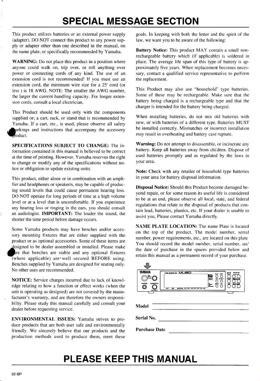
Yamaha is not responsible for damage caused by improper handling or operation.
viii
Page 11
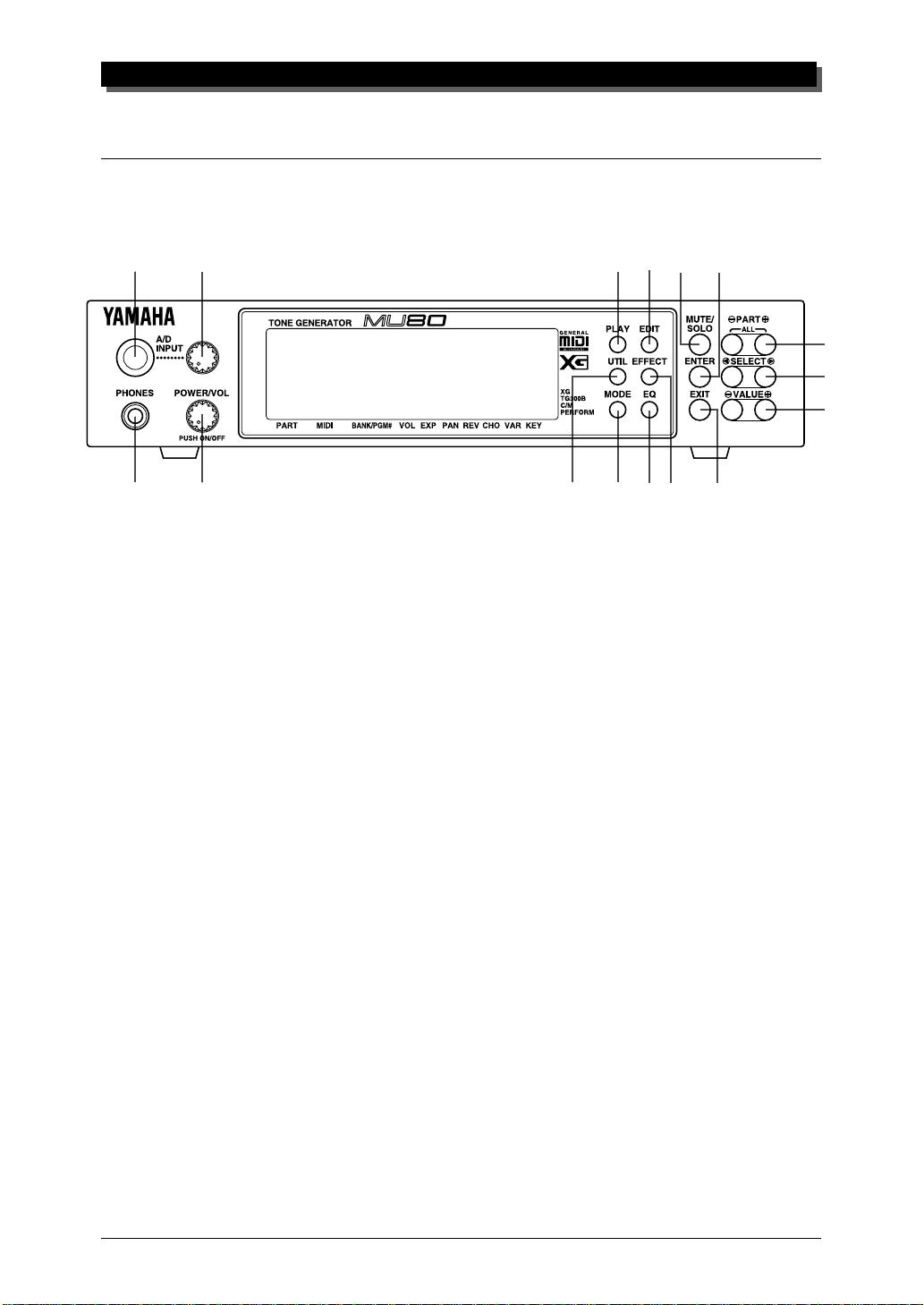
The Controls of the MU80
Front Panel
1
3
2
4
1
A/D INPUT jack
For connection of a microphone, electric guitar or other electronic instrument.
(Accepts either stereo or mono 1/4" plugs.)
THE CONTROLS OF THE MU80
6
58
7
10
11
9
13
12
14
15
16
2
A/D INPUT level control
For control of the A/D input level.
3
PHONES jack
For connection to a set of stereo headphones (mini-pin).
4
POWER/VOL control
Pressing this turns the power on and off. Turning it adjusts the overall volume
of the MU80.
5
PLAY button
For entering the Play mode and switching among the different Play displays.
(See page 34.)
6
UTIL (UTILITY) button
For entering the Utility mode. (See page 15.)
7
MODE button
For entering the Sound Module mode. (See page 34.)
8
EDIT button
For entering the Edit mode. (See page 44.)
1
Page 12
THE CONTROLS OF THE MU80
1
2
8
5
11
12
14
15
16
3
4
9
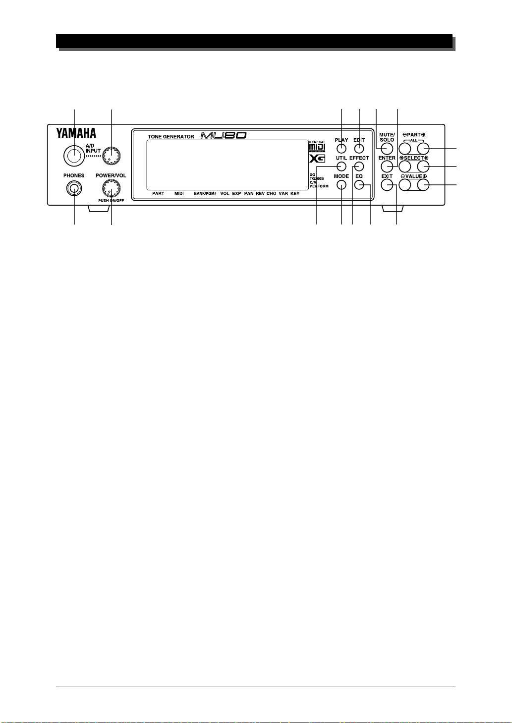
EFFECT button
For entering the Effect Edit mode. (See page 86.)
10
EQ button
For entering the EQ Edit mode. (See page 96.)
11
MUTE/SOLO button
Pressing this alternately mutes or solos the selected Part. (See page 23.)
12
ENTER button
For calling up menu items in the display and for executing certain functions
and operations. Double-clicking this (pressing it twice quickly) calls up the
System Exclusive hexadecimal message for the current function and parameter value.
13
EXIT button
For leaving various display pages and returning to previous displays. Also for
canceling certain functions and operations.
7
6
9
10
13
14
PART -/+ buttons
For selecting different Parts. In the Effect Edit mode, these can be used to
switch among the different effects. Pressing these together enters and exits
from All Part control. (See page 17.)
15
SELECT </> buttons
For selecting the various menu items, parameters and controls on the display.
16
VALUE -/+ buttons
For changing the value of a selected parameter or control.
2
Page 13
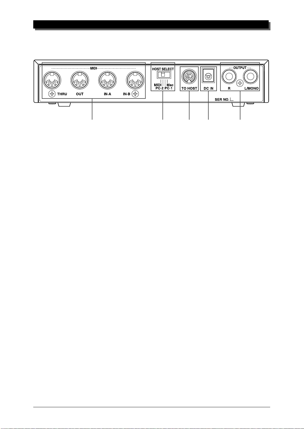
Rear Panel
THE CONTROLS OF THE MU80
1
1
MIDI THRU, MIDI OUT and MIDI IN A/B terminals
For connection to other MIDI devices, such as a MIDI keyboard, tone generator, sequencer, or to a computer that has a MIDI interface. MIDI IN A and B
are independent MIDI ports, allowing full 32-channel MIDI input. MIDI OUT
is for data dumps to another MIDI device, while MIDI THRU is for “daisychain” connection of additional MU80s or other MIDI instruments. (See page
12 for more information on MIDI connections.)
2
HOST SELECT switch
For electing the type of host computer. (See page 12.)
3
TO HOST terminal
For connection to a host computer that does not have a MIDI interface. (See
page 26.)
4
DC IN jack
For connection to the PA-1207 AC power adaptor.
5
OUTPUT R, L/MONO jacks (Right, Left/Mono)
For connection to a stereo amplifier/speaker system. When using a mono system, connect it to the L/MONO jack.
2
34 5
3
Page 14

THE MU80 — WHAT IT IS AND WHAT IT CAN DO
The MU80 — What It Is and What It Can Do
What It Is…
The MU80 is a compact, highly portable and easy-to-use tone generator. It
features full General MIDI Level 1 compatibility with 128 General MIDI
Voices and 9 drum kits. It also provides new XG-MIDI (Extended General
MIDI) compatibility, with a total of 537 Voices and 11 drum kits. The
MU80 has 64-note polyphony and is 32-Part multi-timbral. In other words,
the MU80 has 32 different Parts, each with its own Voice, so that up to 32
different Voices can be sounded simultaneously. Since the MU80 features
dual MIDI input ports (A and B), 16 Parts can be played from one MIDI
port and the remaining 16 from the other port.
The MU80 also has a TO HOST terminal for easy interfacing with a
computer, allowing you to play the Voices using your favorite music software. This is where the advanced multi-timbral capabilities come in, letting
you playing sophisticated arrangements using up to 32 different Voices at
the same time.
The MU80 also features a special Performance mode, in which four Parts
are played simultaneously over a single MIDI channel. Connected to a MIDI
keyboard, this effectively gives you four tone generators in one. The MU80
gives you two sets of 64 factory-programmed Preset Performances plus 128
Internal Performance locations for your own original Performances.
About General MIDI
General MIDI is a new addition to the worldwide MIDI standard. MIDI, as
you know, stands for Musical Instrument Digital Interface, and makes it
possible for various electronic musical instruments and other devices to
“communicate” with each other. For example, by connecting a sequencer
to the MU80’s MIDI IN terminal, you could play back a song on the
sequencer using the Voices of the MU80.
So, where does General MIDI fit in all of this? One of the most important features of General MIDI is in the standardization of Voices. This
means that a song recorded in the General MIDI format can be played back
on any General MIDI compatible tone generator and sound just as the composer intended. For example, if there is an alto sax solo in the song, it will
be played by an alto sax Voice on the General MIDI tone generator (and
not by a tuba or harpsichord!). Since the MU80 is fully compatible with
General MIDI, you can take advantage of the vast wealth of musical material recorded in that format.
4
Page 15

What It Can Do…
Here are a few ideas on how you can use the MU80. The list below is not
comprehensive, but is meant to be a general guide to the possibilities and
provide a starting point or springboard for your own creative ideas and explorations.
Using With MIDI Keyboard
Use the MU80 as supplementary tone generator with your MIDI keyboard
and play the Voices of both instruments in a layer together. Or, use the convenient Performance mode, and play four Voices on the MU80 at once. You
can split the four Voices across the keyboard, playing each from a different
register. Or you can create sophisticated velocity splits, in which a different
Voice is heard depending on how strongly you play the keyboard. Or use
keyboard and velocity splits together for even greater flexibility.
THE MU80 — WHAT IT IS AND WHAT IT CAN DO
Using With a Computer or Sequencer
Home Studio Setup
The MU80 integrates instantly and easily into any existing setup. If you
have a MIDI keyboard, computer and sequencing software, the MU80 with
its high-quality Voices and multi-timbral capabilities can expand your home
studio system.
Carry It With You
If you have a laptop computer (and sequencing software), simply connect
the MU80, plug in some headphones and you’ve got a complete, high-powered music making system that’s ready to go wherever you go. Use it for
composing, arranging, practicing or making/playing demos for your band.
Multimedia
Since it’s portable and compatible with General MIDI, the MU80 is a natural for multimedia applications. Bring it with you to a presentation — since
the computer interface is built-in to the MU80, it hooks up instantly and
easily to the computer’s serial port or printer port, without the need for any
other equipment.
5
Page 16
THE MU80 — WHAT IT IS AND WHAT IT CAN DO
About the Modes of the MU80
The MU80 has two main operating modes: Multi and Performance. In
Multi mode, the MU80 is a 32-Part multi-timbral tone generator; in Performance mode, the MU80 effectively functions as four tone generators
controlled over a single MIDI channel.
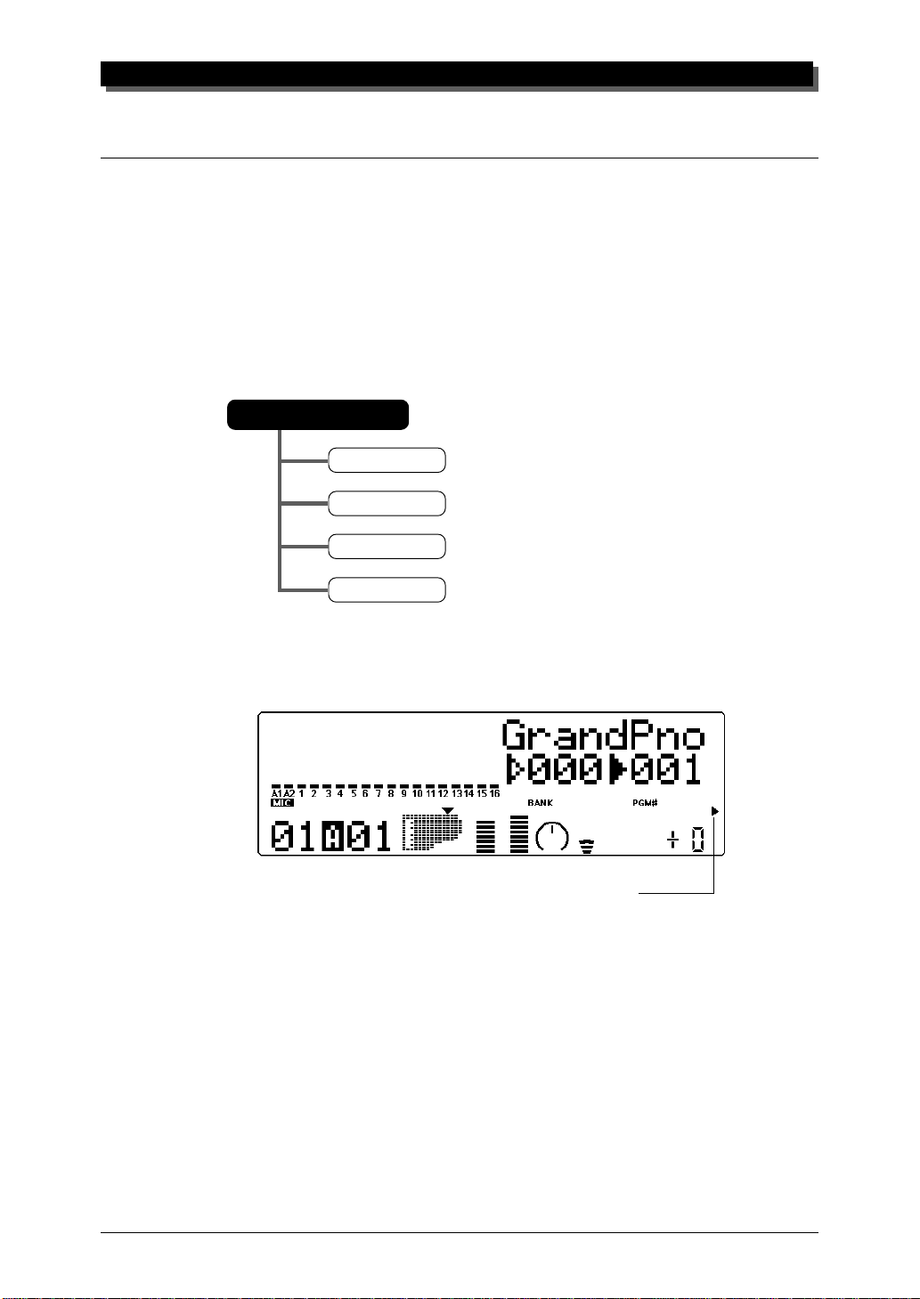
Which mode the MU80 is in depends on the selected Sound Module
mode. If XG, TG300B or C/M are selected, the MU80 automatically sets
itself to the Multi mode. When PFM is selected, the MU80 is in the Performance mode.
Sound Module Mode
XG
TG300B
C/M
Performance
The bottom right of the display indicates the currently selected Sound Module mode.
Selected Sound Module mode.
Play Modes and the Part Controls
Once the operating mode of the MU80 is set (Multi or Performance), there
are two main ways you can use the MU80: playing and editing. In the Play
modes, you play the Voices; in the various Edit modes, you change their
settings.
Within the Play modes are the Part controls. These let you make basic
settings for the Parts. The Single Part controls allow you to make independent settings for each Part, while the All Part controls allow you to change
the overall settings of all Parts. (See page 36 for more information.)
6
Page 17
THE MU80 — WHAT IT IS AND WHAT IT CAN DO
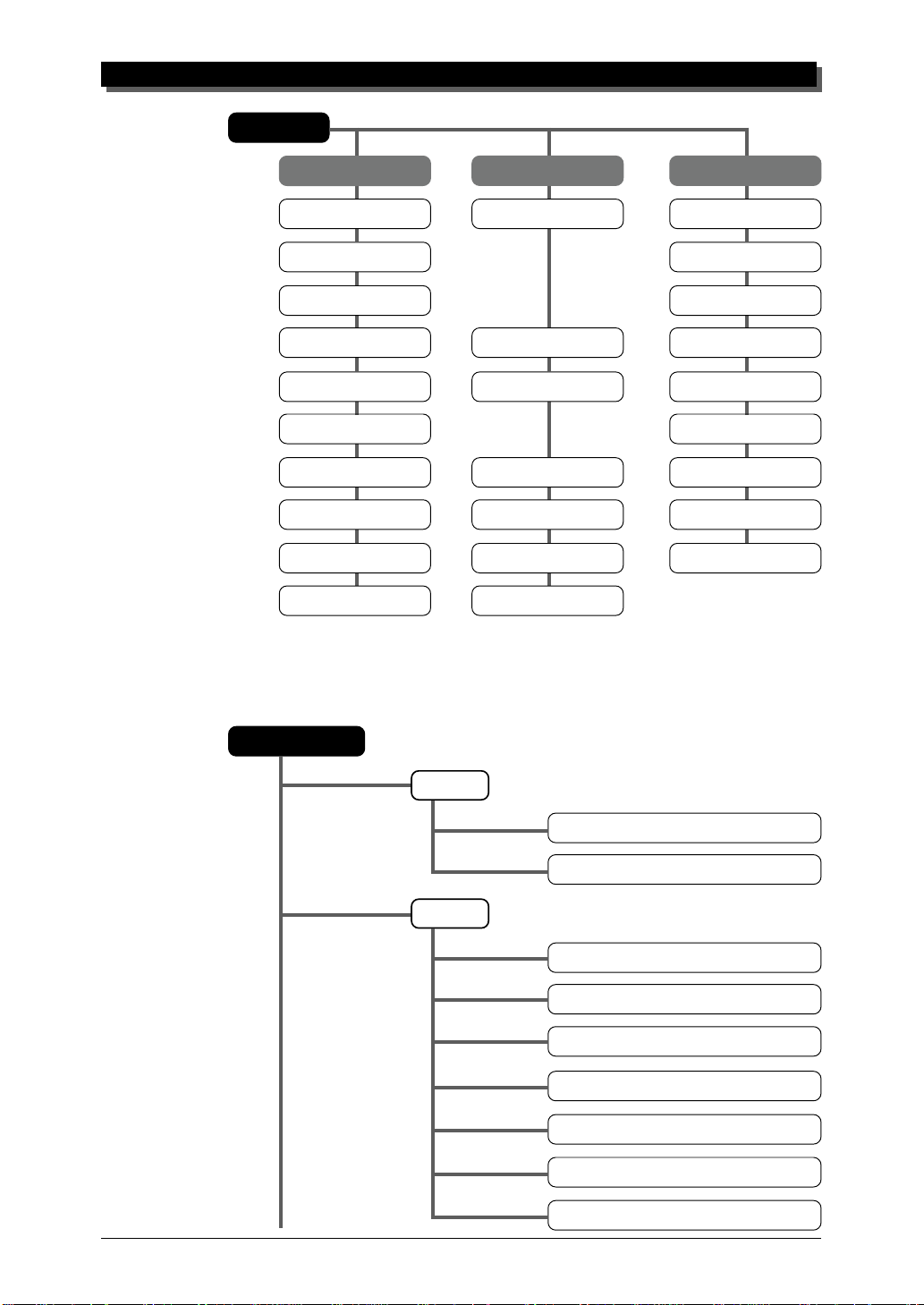
Play Mode
Part 1 … 32 A ll Part A/D
Receive Channel Device Number Receive Channel
Bank Number Source Variation
Program Number A/D Source
Volume Master Volume Volume
Expression Master Attenuator Expression
Pan Pan
Reverb Send Reverb Return Reverb Send
Chorus Send Chorus Return Chorus Send
Variation Send Variation Return Variation Send
Note Shift Transpose
The MU80 has several different Edit modes, each with various menus and
operations:
Part Edit Mode
Filter
Cutoff Frequency
Resonance
EG
EG Attack Time
EG Decay Time
EG Release Time
Pitch EG Initial Level
Pitch EG Attack Time
Pitch EG Release Level
Pitch EG Release Time
7
Page 18
THE MU80 — WHAT IT IS AND WHAT IT CAN DO
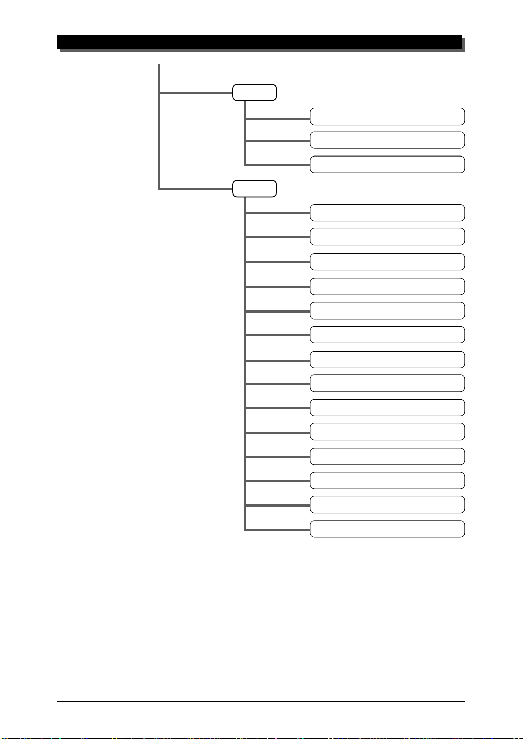
Vibrato
Others
Vibrato Rate
Vibrato Depth
Vibrato Delay
Detune
Part Mode
Mono/Poly Mode
Velocity Sensitivity Depth
Velocity Sensitivity Offset
Note Limit Low
Note Limit High
Portamento Switch
Portamento Time
Velocity Limit Low
Velocity Limit High
Dry Level (VarConnect=SYS)
Pitch Bend Control
MW LFO Pitch Moduration Depth
8
Page 19
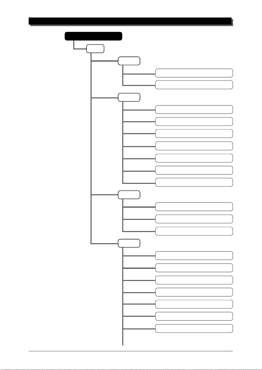
Performance Edit Mode
Part
THE MU80 — WHAT IT IS AND WHAT IT CAN DO
Filter
Cutoff Frequency
Resonance
EG
EG Attack Time
EG Decay Time
EG Release Time
Pitch EG Initial Level
Pitch EG Attack Time
Vibrato
Others
Pitch EG Release Level
Pitch EG Release Time
Vibrato Rate
Vibrato Depth
Vibrato Delay
Detune
Mono/Poly Mode
Velocity Sensitivity Depth
Velocity Sensitivity Offset
Note Limit Low
Note Limit High
Portamento Switch
9
Page 20
THE MU80 — WHAT IT IS AND WHAT IT CAN DO
For more information on each of these modes and their menus, see the respective sections in the Reference section.
Portamento Time
Velocity Limit Low
Velocity Limit High
Dry Level (VarConnect=SYS)
MW LFO Pitch Moduration Depth
MW LFO Filter Moduration Depth
Pitch Bend Control
Assignable Control 1 Filter Control
Assignable Control 1 Amplitude Control
Utility Mode
The Utility mode lets you set functions related to the overall operation of
the MU80, such as Master Tune, display Contrast and reception of certain
MIDI messages that affect the entire instrument. Included also are miscellaneous operations, such as sending bulk data to a data storage device, initializing of the MU80 settings, and playing the special Demo song.
Part Edit Mode
The Part Edit mode allows you to change certain settings for each individual Part, such as those of the Filter, EG (Envelope Generator), and many
other settings. The internal Voices can be sounded during editing, allowing
you to hear the effects of your edits.
10
Page 21
G
When using your MU80 for the first time, read through this
short section of the manual. It guides you step-by-step in using many of the basic operations: setting the instrument up,
connecting it properly to other equipment, and — most importantly — playing it.
UIDED
T
OUR
Chorus Distortion Dump EffectEQ
Initialize Reverb System U tility Variation
Page 22
GUIDED TOUR
Setting Up Your MU80
In this introductory section, you’ll learn how to set up the MU80 for use
with a MIDI keyboard. (Setting up for use with a computer is covered on
page 26.)
What You’ll Need
☛ The MU80 and the included power adaptor.
☛ A MIDI keyboard, electronic piano, or any instrument that can output
MIDI data.
☛ An amplifier/speaker system, preferably stereo. Alternately, you can use
a set of stereo headphones.
☛ Audio connecting cables.
☛ A MIDI cable.
Making the Connections
CAUTION!
Before making any connections, make sure that all equipment to be connected is turned off,
and that the MU80 power adaptor is not connected to an electrical outlet.
Operation
1 Connect one end of the MIDI cable to the MIDI OUT terminal of
the MIDI keyboard and the other to MIDI IN-A of the MU80 (as
shown in the illustration below).
2 Connect the audio cables from the R and L/MONO OUTPUT
jacks of the MU80 to the appropriate inputs on the amplifier
speaker system (as shown in the illustration below).
If the amplifier has only one input, use the L/MONO jack on
the MU80. If you are using stereo headphones, connect them to
the front panel PHONES jack.
3 Set the HOST SELECT switch on the MU80 to MIDI.
4 Connect the power adaptor to the DC IN terminal on the MU80
and plug the adaptor into an appropriate electrical outlet.
12
Page 23

GUIDED TOUR
CAUTION!
● Do not attempt to use an AC adaptor other than the PA-1207. The use of an incompatible
adaptor may result in irreparable damage to the MU80, and even pose a serious shock
hazard.
● Be sure to disconnect the power adaptor from the outlet when the MU80 is not in use.
Power
Adaptor
Amplifier
Speaker System
PHONES
R
DC INL/MONO
MIDI IN-A
MIDI CABLE
MIDI OUT
MIDI Keyboard
13
Page 24

GUIDED TOUR
Powering Up and Playing the Demo Song
Once you’ve connected everything properly, you’re ready to turn the MU80
on and start playing it. However, a small word of caution before you begin:
Follow the instructions given below to avoid possible damage to your
equipment and speakers.
Powering Up
Operation
1 If you haven’t done so already, press the POWER/VOL control
on the MU80.
After the greeting display, the following display will appear:
2 Turn on the power of your MIDI keyboard.
3 Make sure that all volume controls (on the MU80 and the con-
nected amplifier) are turned down. Then, turn on the power of
your amplifier speaker system.
4 Finally, set the volume control on the MU80 to about the mid-
way position and set the volume on the amplifier to a suitable
level.
14
Page 25

Playing the Demo Song
Now that you’ve set everything up properly, try playing the built-in Demo
Song. This showcases the high-quality Voices and the AWM2 tone generation system of the MU80.
Operation
1 Press the UTILITY button.
2 Select “DEMO” with the SELECT w buttons and press the
ENTER button.
GUIDED TOUR
3 Press the ENTER button to start the Demo Song.
The Demo Song starts playing immediately and repeats indefinitely
until stopped (in step 4 below). Playback of the individual Parts of
the song is shown graphically by the “level meter” bars in the display.
NOTE
During Demo Song playback, all panel controls (except the EXIT button and the VOLUME
control) cannot be used.
4 To stop playback of the song, press the EXIT button.
5 To exit from the Demo Song function, press the EXIT button
again.
15
Page 26

GUIDED TOUR
Playing Your MU80 With a MIDI Keyboard
Operation
Play some notes on your MIDI keyboard.
If you’ve carefully followed all instructions up to now, one of
the “level meter” bars in the display should move — and you
should be able to hear the sound of the MU80 as you play.
The “level meter” bar indicates the “level” (velocity) of the
incoming MIDI data.
The number under the moving “level meter” indicates the Part number.
NOTE
If your MIDI keyboard is transmitting on channel 1, the Voice of Part 1 should sound. If it is
transmitting on another channel, another Part’s Voice will sound. For the sake of these introductory instructions, set your keyboard so that it transmits on channel 1. (Refer to the owner’s manual of that instrument if necessary.)
16
Page 27

Selecting Voices
In this brief section, you’ll learn how to select other Voices. You can do this
directly from the panel of the MU80 or remotely, from your MIDI keyboard.
Operation
1 First, select a Part. Use the PART q buttons to select Part 1.
Press the appropriate button until “01” appears in the PART section of the display.
GUIDED TOUR
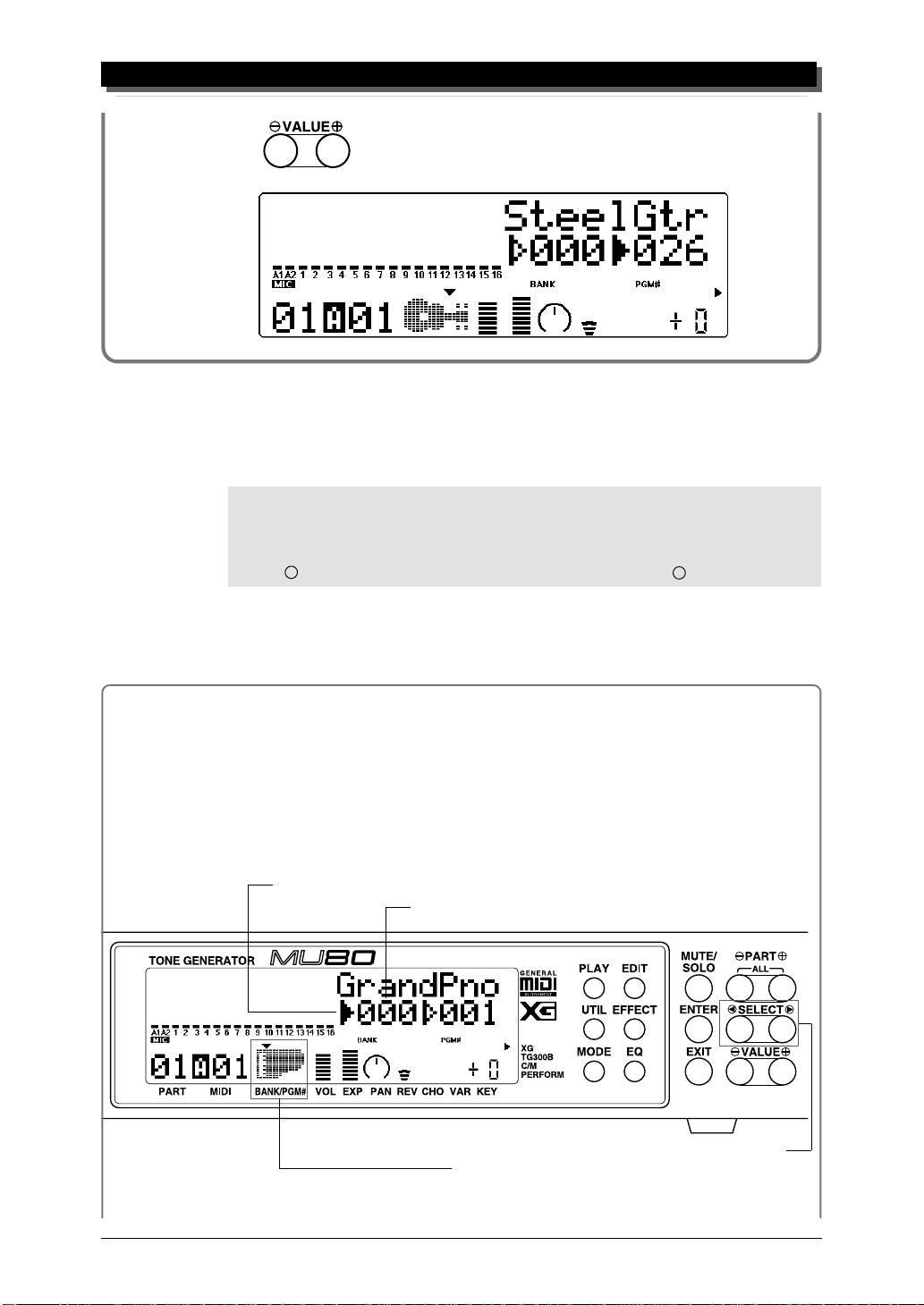
2 Use the SELECT w buttons to move the arrow cursor to the
right side of the instrument icon, as shown below.
Solid arrow at Voice number (currently selected).
Arrow cursor (indicates currently selected control).
The arrow is directly above “PGM#” on the panel,
indicating that Program Number is currently selected.
Voice name.
Instrument icon of current Voice.
MIDI receive channel for current Part.
Part number. (This is selectable only with the PART q buttons.)
Voice number (program number).
Use these to move arrow cursor.
3 Use the VALUE q buttons to change the Voice number. In
the display below, Voice number 26 has been selected.
17
Page 28
GUIDED TOUR
Play this new Voice from the keyboard. Try selecting other Voices and play
them as well. (For a list of all the available Voices, refer to the SOUND
LIST & MIDI DATA booklet.
HINT
You can rapidly move through the values by holding down one of the VALUE q buttons.
You can move even more rapidly by holding down one button and then pressing and holding down the other. For example, to rapidly advance (increase) the value, hold down the
VALUE + button and simultaneously press and hold down the VALUE – button.
Changing the Voice Bank
In the current Sound Module mode (XG), several banks of Voices are available.
Each bank can contain up to 128 different Voices.
Operation
1 Use the SELECT w buttons to move the arrow cursor to the left side of
the instrument icon, as shown below.
Solid arrow at Bank number (currently selected).
Bank number.
Use these to move arrow cursor.
Arrow cursor (indicates currently selected control).
The arrow is directly above “BANK” on the panel,
indicating that Bank number is currently selected.
18
Page 29

GUIDED TOUR
2 Use the VALUE q buttons to change the Bank number.
3 Finally, use the SELECT w buttons again to move the arrow cursor back
to the right side of the instrument icon — for Voice selection.
Selecting Voices From Your MIDI Keyboard
You can also select Voices remotely from the connected MIDI keyboard. Though the actual operation may differ depending on the
keyboard used, the general procedure is the same. (Refer to the
owner’s manual of your instrument for specific instructions.)
Operation
1 Make sure that your keyboard is set up to send Program Change
messages.
2 Use the panel controls to select a program on your keyboard.
Generally, if everything has been set up properly, the Voice number
and name on the MU80 will change, and will be the same number
as the program number you selected on your keyboard.
19
Page 30

GUIDED TOUR
Changing Some of the Settings — Part Controls
You can make changes to each individual Part by using the Part controls.
These are always displayed in the Play mode, giving you at-a-glance confirmation of the various basic settings of the MU80. Let’s take a look at the
Play display again:
Voice name, bank number and program number
for the selected Part.
Note Shift setting
for the selected Part.
Variation Send setting
for the selected Part.
Chorus Send setting for the
selected Part.
Reverb Send setting for the
selected Part.
Pan setting for the selected Part.
Expression setting for the selected Part.
Volume setting for the selected Part.
MIDI receive channel for the selected Part.
Part number.
Each of these settings can be made independently for each of the Parts. For
example, each Part could have a different Volume setting, or a different Pan
setting. Try going through the brief sections below and making some
changes in the Part controls yourself.
Selecting another Part and changing its MIDI channel
Here we’ll select Part 2 and change its MIDI channel to 1, so that it
matches the MIDI channel of Part 1. This allows you to play the Voices of
both Part 1 and Part 2 over MIDI channel 1.
20
Page 31

GUIDED TOUR
Operation
1 Use the PART q buttons to select Part 2.
Part 2.
2 Use the SELECT w buttons to call up the “Rcv CH” display
below.
Current MIDI Receive Channel.
3 Use the VALUE q buttons to change the MIDI Receive Chan-
nel to “A01.”
4 Finally, use the SELECT w buttons to move the arrow cursor
back to the instrument icon (so that the Voice name is displayed),
and play the MIDI keyboard again.
Both “level meter” move together.
If both Parts 1 and 2 have been set to MIDI channel 1, both of their “level
meters” should move together as you play. And, if the two Parts are set to
different Voices, you should hear two different Voices sound at the same
time. (To change the Voice for a Part, refer back to Selecting Voices above.)
21
Page 32

GUIDED TOUR
Changing the Volume and Pan settings of a Part
Now that you’re playing two Voices at the same time, you may want to adjust their settings. Here, we’ll change the Volume and Pan settings of one
Part’s Voice.
Operation
Use the PART q buttons to select the desired Part (Part 1 or 2).
1
2 Use the SELECT w buttons to call up the “Volume” display
below.
Current Volume setting.
3 Use the VALUE q buttons to change the setting, and play the
keyboard as you make changes.
4 Now that you’ve adjusted the Volume balance of the two Voices,
change one of the Part’s Pan setting. Use the SELECT w but-
tons to call up the “Pan” display below.
Current Pan setting.
5 Use the VALUE q buttons to change the setting, and play the
keyboard again as you make changes.
If you want, try making changes to some of the other Part controls. The
procedure is the same: 1) Use the PART q buttons to select a Part, 2)
use the SELECT w buttons to choose the desired control, and 3) use
the VALUE q buttons to change the setting. For more information on
the Part controls, see page 36.
22
Page 33
Using Mute/Solo
The MU80 has convenient Mute and Solo functions for selectively muting
or soloing any of the 32 Parts and A/D Parts A1 and A2. This is especially
useful when playing back several Parts from a connected computer or
sequencer. Mute lets you silence one Part to hear how all of the other Parts
sound without it. Solo lets you isolate a single Part, to hear how that Part
sounds by itself.
Mute and Solo are effective tools that help you as you edit the Parts,
since they allow you to better hear how the changes you make affect specific Voices as well as the overall sound.
Operation
While playing the keyboard (or during playback of a song from a
sequencer), press the MUTE button. Each press cycles through the
three functions: Mute, Solo and Normal operation.
GUIDED TOUR
The selected Part is muted, while all other Parts sound normally.
The selected Part is soloed, while all other Parts are muted.
All Parts sound normally.
23
Page 34

GUIDED TOUR
Using the A/D Input
The MU80 features a special A/D (Analog-to-Digital) Input function that
allows you to connect a microphone, electric guitar or other instrument and
mix in those signals with the MU80’s Voices. A/D Input is perfect for singing along with your keyboard performance, since it allows you to blend the
two signals without the need for an external mixer. Or you can use it to sing
or play guitar over backing tracks played from a MIDI sequencer . There are
two A/D Parts — A1 and A2 — and they include several different pre-programmed settings that take advantage of the built-in effects of the MU80.
Operation
1 Turn down the A/D INPUT control on the front panel.
2 Connect the microphone or instrument to the A/D INPUT jack.
3 Use the PART q buttons to select Part A1.
24
Page 35

GUIDED TOUR
4 Use the SELECT w buttons to move the arrow cursor to
PGM#, as shown below, and use the VALUE q buttons to se-
lect number 002.
5 Move the arrow cursor to BANK (with the SELECT w buttons)
and use the VALUE q buttons to select the type of input: Mic,
Guitar, Keyboard or Audio. This determines the gain level of the
input. Select the type corresponding to the input you’ll use.
6 Slowly bring up the A/D INPUT control on the front panel and
play the instrument (or sing into the microphone) until the level
is appropriate.
7 Now, move the arrow cursor back to PGM# (with the SELECT
w buttons) and try selecting some different A/D programs
(with the VALUE q buttons).
The available programs have been specially programmed to suit the type of
input selected. For example, programs for Mic input include Karaoke and
Vocal; Guitar input programs include Tube, Stack and Phaser. Explore
some of these settings on your own with a microphone and different instruments.
25
Page 36

GUIDED TOUR
Setting Up the MU80 in Your Music System
As you learned in the section The MU80 — What It Is and What It Can
Do on page 4, the MU80 can be integrated into a variety of setups. It would
be impossible to cover all connection possibilities in a short manual as this;
however, the section below will help in quickly setting up the MU80 and
using it in your system.
Connecting With a Computer
The MU80 features a built-in host computer interface, allowing you to directly connect it to your computer — eliminating the need of installing a
special MIDI interface to your computer. The MU80 can be used with the
following computers: Apple Macintosh, IBM PC and the NEC PC-9800
Series.
If your computer has a MIDI interface you may want to connect the
MU80 to it, rather than using the host computer interface on the MU80.
(See the section “Connecting to Other MIDI Devices” on page 28.)
Depending on the computer or interface used, set the HOST SELECT
switch to the appropriate setting: MIDI, PC-1 (NEC computers), PC-2
(IBM and clones), or Mac (Macintosh). For information on the types of cables that can be used for connection, see the section “MIDI/Computer
Connecting Cables” on page 32.
26
Macintosh
Follow these instructions if you have an Apple Macintosh not equipped
with an external MIDI interface. Connect the TO HOST terminal on the
MU80 to the Modem or Printer port on the Macintosh.
Modem or
Printer Port
Macintosh
Page 37

GUIDED TOUR
Operation
1 Set the HOST SELECT switch to Mac.
2 Connect the MU80 to the host computer, as shown in the illus-
tration above. Use a standard Macintosh cable (8-pin Mini DIN
on both ends; see page 32).
3 Turn on the the host computer, then the MU80.
4 Start up your music software, and set up the appropriate options
on the software for operation with the MU80.
The options you may have to set include:
gg
g
MIDI Interface Type
MIDI Time Piece
Clock
Standard MIDI Interface
gg
gg
g
On (for controlling all 32 Parts of the MU80)
gg
gg
g
1 MHz
gg
Other options and settings may have to be made as well. Refer to the owner’s manual of your particular music software for more information.
IBM PC and Clones
Follow these instructions if you have an IBM PC/AT or compatible computer
not equipped with an external MIDI interface. Connect the TO HOST terminal on the MU80 to one of the computer’s serial ports, COM 1 or COM 2.
Serial Port
IBM PC/AT or Compatible Computer
NOTE
Your music software must be able to recognize the TO HOST connection. Consult your
Yamaha dealer for more details. If your software is not compatible, you can still use the
MU80 by installing a MIDI interface (internal card or external) to the computer.
27
Page 38

GUIDED TOUR
Operation
1 Set the HOST SELECT switch to PC-2.
2 Connect the MU80 to the host computer, as shown in the illus-
tration above. Use a standard computer cable (8-pin Mini DIN
to 9-pin D-SUB; see page 32).
3 Turn on the the host computer, then the MU80.
4 Start up your music software, and set up the appropriate options
on the software for operation with the MU80.
Refer to the owner’s manual of your particular music software for more information.
Connecting to Other MIDI Devices
The MU80 is equipped with MIDI IN and OUT terminals, allowing you to use
it in any MIDI system. Example uses for the built-in MIDI interface include:
☛ Connecting to a MIDI keyboard (for playing the sounds of the MU80
from that keyboard).
☛ Connecting to a computer equipped with a MIDI interface (either in-
ternal or external).
☛ Connecting to a hardware sequencer (such as the Yamaha QY300).
☛ Connecting to a MIDI data storage device (such as the Yamaha MDF2
MIDI Data Filer).
MIDI CABLE
MIDI OUT MIDI IN
28
Sequencer
Page 39

MIDI CABLE
MIDI IN MIDI INMIDI OUT MIDI OUT
MDF2
MIDI CABLE
MIDI IN MIDI INMIDI OUT MIDI OUT
GUIDED TOUR
MIDI Keyboard
Operation
1 Set the HOST SELECT switch to MIDI.
2 Connect the MU80 to the appropriate MIDI device, as shown in
the illustrations above. Use a standard MIDI cable (see page 32).
3 Turn on the the connected device, then the MU80.
4 If you are using a computer, start up your music software, and
set up the appropriate options on the software for operation with
the MU80.
29
Page 40

GUIDED TOUR
Using the MU80 with a MIDI Data Storage Device
You can also use the MU80 with a MIDI data storage device, such as the
Yamaha MDF2 MIDI Data Filer. This lets you save or back up whatever
changes you’ve made in the settings of the Utility and Part Edit modes, as
well as changes to the EQ built-in effects and Performances. Then, when
you want to recall those settings, you can transfer the appropriate data from
the storage device.
The MDF2 also allows you to play compatible song data on the MU80
directly from the MDF2 itself, without the need of a sequencer.
Make sure that the MU80 is properly connected to the data storage de-
vice (via MIDI). (Refer to page 28 for the connection example.) Use the
Dump Out function (page 102) to send data to the device. Also refer to the
owner’s manual of your data storage device for specific operating instructions in receiving or sending data.
30
Page 41

Data Flow Block Diagram
Sound
Module
A1~16CH
TO HOST IN-B IN-A OUT THRU
Sound
Module
B1~16CH
Sound
Module
A1~16CH
TO HOST IN-B IN-A OUT THRU
Sound
Module
B1~16CH
When HOST SELECT switch is set to MIDI (31,250 bps):
TO HOST IN-B IN-A OUT THRU
GUIDED TOUR
Sound
Module
A1~16CH
Sound
Module
B1~16CH
When HOST SELECT switch is set to PC-1/Mac (31,250 bps):
When HOST SELECT switch is set to PC-2 (38,400 bps):
31
Page 42

GUIDED TOUR
MIDI/Computer Connecting Cables
MIDI
Standard MIDI cable. Maximum length 15 meters.
DIN 5-PIN DIN 5-PIN
4
2
5
4
2 (GND)
5
Mac
Apple Macintosh Peripheral cable (M0197). Maximum length 2 meters.
MINI DIN
8-PIN
1
2
3
4 4 (GND)
5 3 (TxD –)
6 8 (RxD +)
7 7 (GP i)
8 6 (TxD +)
2 (HSK i)
1 (HSK o)
5 (RxD –)
MINI DIN
8-PIN
PC-1
8-pin MINI DIN to D-SUB 25-pin cable. If your PC-1 type computer has a
9-pin serial port, use the PC-2 type cable. Maximum length 1.8 meters.
MINI DIN
8-PIN
1
2
3
4 7 (GND)
8
5 2 (TxD)
5 (CTS)
4 (RTS)
3 (RxD)
D-SUB
25-PIN
PC-2
8-pin MINI DIN to D-SUB 9-pin cable. Maximum length 1.8 meters.
MINI DIN
8-PIN
1
2
3
4 5 (GND)
8
5 3 (TxD)
This concludes your basic tour of the important functions of the MU80. To find out
more about how to best use your MU80, look through the Reference section that follows and try out some of the functions and operations that interest you.
32
8 (CTS)
7 (RTS)
2 (RxD)
D-SUB
9-PIN
Page 43

R
The Reference section of this manual covers in detail all of
the functions of the MU80. Refer to it when you need information about a specific function, feature or operation.
EFERENCE
Chorus Distortion Dump EffectEQ
Initialize Reverb System U tility Variation
Page 44

MULTI MODE
Multi Mode
In the Multi mode, the MU80 performs as a multi-timbral tone generator capable of playing up to 32 Parts simultaneously, over 32 MIDI channels. Normally,
the MU80 should be set to Multi mode when using it with a sequencer and
General MIDI song data. There are three Multi modes: XG, TG300B and C/M.
Each mode provides compatibility with different music software and hardware.
XG: This stands for Extended General MIDI and provides the full poten-
tial of the MU80, giving you access to all 537 Voices.
TG300B: This mode provides compatibility with the GM-B mode of the TG300
Tone Generator.
C/M: This mode provides compatibility with most computer music soft-
ware not supported by the other two Multi modes.
NOTE
When set to the TG300B mode, the MU80 may not be able to play TG300-specific song data with complete
accuracy. However, MIDI data designed for other computer music tone generators is compatible with the MU80.
To set the Multi mode:
1 Press the MODE button.
2 Use theg SELECT w buttons to select the desired Multi mode:
XG, TG300B or C/M.
3 Press the EXIT button or the PLAY button to return to the Play
display.
XG
TG300B
C/M
PERFORMANCE
34
Indicates currently selected mode.
The currently selected mode setting is shown by the arrow at the bottom
right of the display.
Page 45

Multi Play Mode
The Play mode (with the main Play display shown below) is the normal operating mode of the MU80. To select the Play mode from any other mode,
press the PLAY button. (The Play mode is also automatically selected
when you turn on the MU80.)
MULTI MODE
Current Part number.
NOTE
Applications that are capable of controlling 32 Parts (e.g., Performer) are set to a clock rate of
1 MHz.
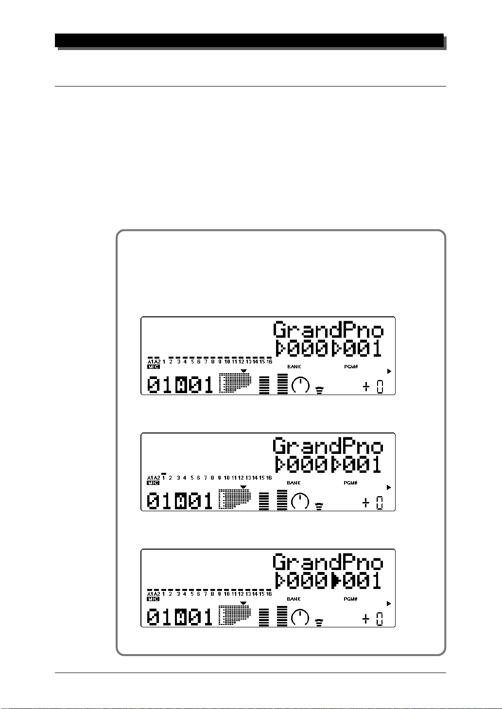
Play Displays
The Play mode has three basic displays, that can be changed according to
your preference. Simply press the PLAY button repeatedly, and the display
alternates as shown below:
Velocity “level meters” for each Part.
MIDI port (A or B) and channel number for currently selected Part.
Voice number and name for
currently selected Part.
1)
Shows full “level meter” indication for the A1 and A2 A/D Parts and Parts
1 … 16. Currently selected parameter (here, Voice number and name) is
displayed at the right side.
35
Page 46

MULTI MODE
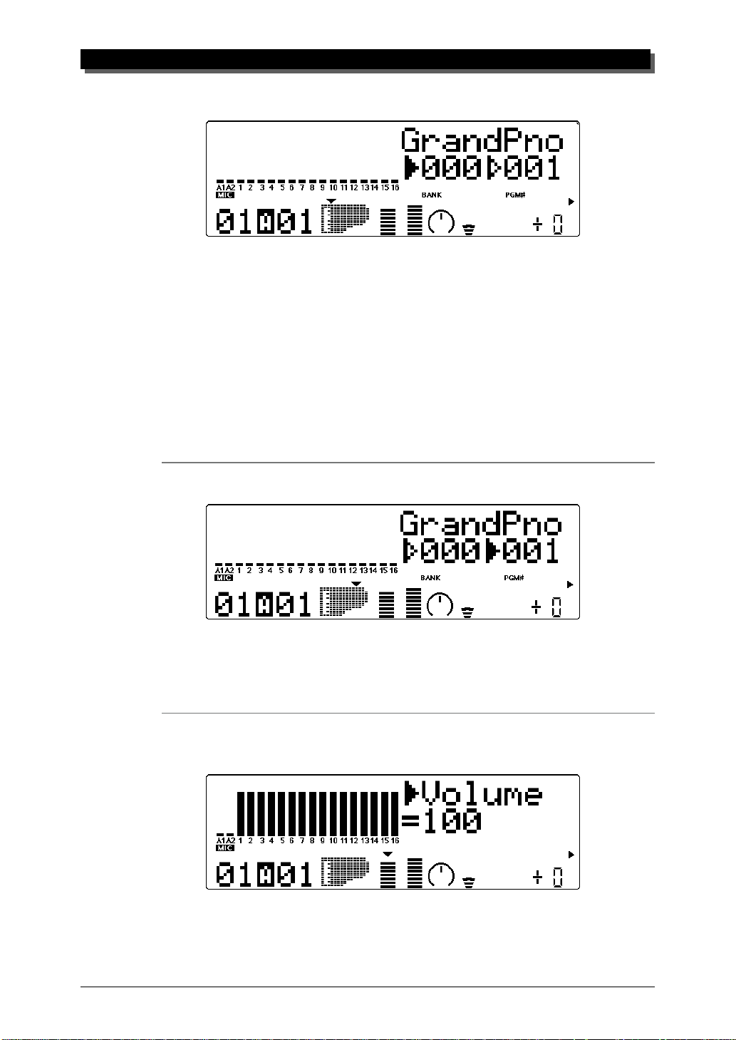
Parts 17 … 32 can be displayed by selecting one of those Parts with the
PART q buttons. For example, when Part 18 is selected, the changes
as shown below:
2)
Shows half “level meter” indication for the A1 and A2 A/D Parts and all 32
Parts. Currently selected parameter (here, Voice number and name) is displayed at top.
3)
Shows full “level meter” indication for the A1 and A2 A/D Parts and all 32
Parts. Currently selected parameter is not displayed.
Part Controls
The Part controls in the Play mode give you tools for adjusting the basic
sound and settings for each Part. The MU80 lets you adjust the various settings for each Part individually (Single Part control) or together (All Part
control). Each of these types is explained in greater detail below.
NOTE
In the Multi mode, no settings can be permanently saved to the internal memory of the
MU80. However, you can use the Dump Out function to save Multi settings to a MIDI data
storage device. (See page 102.)
36
Page 47

Single Part Control
The Single Part controls include: MIDI Receive Channel, Bank Number,
Program Number, Volume, Expression, Pan, Reverb Send, Chorus Send,
Variation Send and Note Shift.
Selecting Single Part Control
Single Part control is automatically called up when the MU80 is turned on.
If All Part is selected, simply press both PART q buttons simultaneously (or press the EXIT button) to return to Single Part.
MULTI MODE
Editing in Single Part
Operation
1 Select the Part to be edited by using the PART q buttons.
2 Select the desired control for the selected Part by using the
SELECT w buttons.
3 Change the value of the selected control by using the VALUE
q buttons.
MIDI Receive Port/Channel
Settings: A1 … A16, B1 … B16
This determines the MIDI IN port (A or B) and the receive channel
(1 … 16) for the selected Part.
37
Page 48
MULTI MODE
Bank Number
Settings:
XG: 000, 001, 003, 006, 008, 012, 014, 016 … 020, 025, 027,
028, 032 … 043, 045, 064 … 072, 096 … 101, SFX
TG300B:000 … 011, 016 … 019, 024 … 026, 032, 033, 040, 080,
126, 127
C/M: Fixed (only one bank)
This determines the bank number of the selected Part’s Voice. Each
bank contains 128 Voices. (Refer to the SOUND LIST & MIDI
DATA booklet.
Program (Voice) Number
Range: 1 … 128
This determines the Voice for the selected Part. (Refer to the
SOUND LIST & MIDI DATA booklet.
Volume
Graphically indicates current Volume setting.
38
Range: 0 … 127
This determines the Volume setting for the selected Part’ s Voice.
Page 49

Expression
Graphically indicates current Expression setting.
Range: 0 … 127
This determines the Expression setting for the selected Part’s Voice.
Pan
Graphically indicates current Pan setting.
MULTI MODE
Settings: Rnd (Random), L63 … C … R63
This determines the stereo position of the selected Part’s Voice. A
setting of “Rnd” (Random) randomly assigns the Voice to a pan po-
sition. This is useful when you want to have different Voices sound
from different random parts of the stereo image. (The Random set-
ting does not affect the A/D input Parts.)
Reverb Send
Graphically indicates current Reverb Send setting.
Range: 0 … 127
This determines the level of the selected Part’s Voice that is sent to the
Reverb effect. A value of 0 results in a completely “dry” Voice sound.
NOTE
Keep in mind that the Reverb effect must be properly enabled and set for this parameter to
work as intended. (See page 86.)
39
Page 50

MULTI MODE
Chorus Send
Graphically indicates current Chorus Send setting.
Range: 0 … 127
This determines the level of the selected Part’s Voice that is sent to
the Chorus effect. A value of 0 results in a completely “dry” Voice
sound (no Chorus effect).
NOTE
Keep in mind that the Chorus effect must be properly enabled and set for this parameter to
work as intended. (See page 88.)
Variation Send
Graphically indicates current Variation Send setting.
40
Settings: off, on (when Variation Connection is set to INS);
0 … 127 (when Variation Connection is set to SYS)
This determines whether the selected Part’s Voice is sent to the Vari-
ation effect or not. A setting of “off” results in no Variation effect
being applied to the Voice.
Note Shift
Graphically indicates current Note Shift setting.
Range: –24 … +24 semitones
This determines the key transposition setting for the Part’s Voice.
Page 51

All Part Control
The All Part controls include: Device Number, Master Volume, Master
Attenuator, Reverb Return, Chorus Return, Variation Return and Transpose.
Keep in mind that these controls affect all Parts equally, and either add
to or subtract from their individual values. For example, if Note Shift on
one Part is set to –12, and Transpose (in All Part) is set to +12, that Part’s
pitch value will actually be 0 or normal.
Selecting All Part Control
To select All Part control, press both PART q buttons simultaneously. (or
press the EXIT button). (“All” appears in the P ART section of the display.)
MULTI MODE
Editing in All Part
Operation
1 Select the desired control for all Parts by using the SELECT
w buttons.
2 Change the value of the selected control by using the VALUE
q buttons.
Device Number (DevNo.)
Graphically indicates current Device Number setting.
Settings: 1 … 16, all
This determines the Device Number for the MU80, a kind of MIDI
“identification” number to distinguish between multiple units. For
41
Page 52

MULTI MODE
example, if you are using more than one MU80, set a different De-
vice Number for each. This is especially important when using the
data dump features. (See page 102.) If you have only one MU80, set
this to “all.”
Master Volume (M.Volum)
Graphically indicates current Master Volume setting.
Range: 0 … 127
This determines the overall Volume of the Parts.
Master Attenuator (M.Attn)
Graphically indicates current Master Attenuator setting.
42
Range: 0 (maximum volume) … 127 (minimum volume)
This determines the level of all Parts, but functions as an attenuator; the
greater the value, the lower the volume. This is useful when you are
playing several songs and want to keep their overall level consistent.
Reverb Return (RevRtn)
Graphically indicates current Reverb Return setting.
Range: 0 … 127
This determines the amount of Reverb return in the overall mix.
Page 53

Chorus Return (ChoRtn)
Graphically indicates current Chorus Return setting.
Range: 0 … 127
This determines the amount of Chorus return in the overall mix.
Variation Return (VarRtn)
Graphically indicates current Variation Return setting.
MULTI MODE
Range: 0 … 127
This determines the amount of Variation return in the overall mix.
Variation Return is only available when the Variation Connection
parameter is set to SYS. (See page 91.)
Transpose
Graphically indicates current Transpose setting.
Range: –24 … +24 semitones
This determines the overall Transpose setting of the Parts.
43
Page 54

MULTI MODE
Multi Edit Mode
The Multi Edit mode features various parameters for controlling the Filter,
the EG (Envelope Generator) and Vibrato. It also features a variety of other
miscellaneous controls grouped in the Others parameters. When a Drum
Part is selected, Drum-related parameters are also available.
To enter the Multi Edit mode, press the EDIT button. When a normal
Part is selected, the following menu appears:
When a Drum Part is selected, the following menu appears:
Filter
44
Part Edit Mode
Filter
Cutoff Frequency
Resonance
The MU80 features a digital filter that can be used to change the timbre of
the Voices. The filter is affected (together with the level) by the EG (Envelope Generator), which allows you to change the timbre over time as well.
(See EG, page 46.)
Page 55
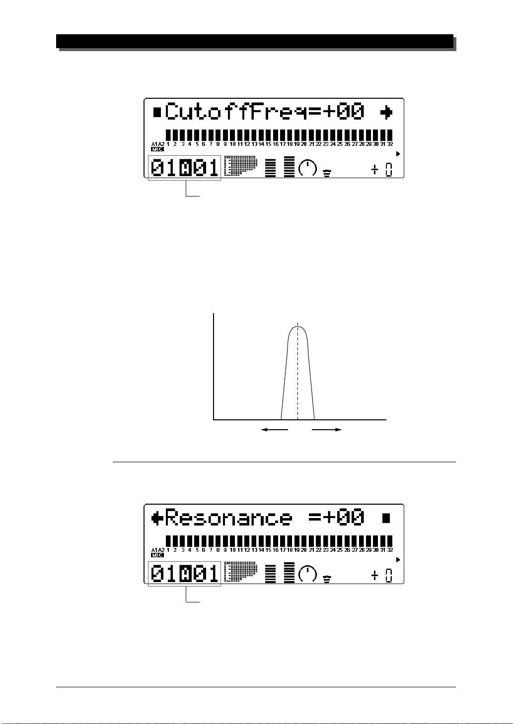
Cutoff Frequency
Graphically shows Cutoff Frequency setting for each Part.
Selected Part and MIDI channel
Range: –64 … +63
Default: 0
This determines the cutoff frequency of the filter, or the frequency
point above which other frequencies are filtered out. Lower cutoff
values create a deeper, more rounded tone, while higher values cre-
ate a thinner, brighter tone.
MULTI MODE
Level
Low (–64) High (+63)
Cutoff
Frequency
Resonance
Graphically shows Resonance setting for each Part.
Selected Part and MIDI channel
45
Page 56

MULTI MODE
Range: –64 … +63
Default: 0
This determines the amount of filter resonance or emphasis of the
Cutoff Frequency parameter above. Higher values increase the em-
phasis of the Cutoff Frequency, producing a higher resonant peak,
while lower values produce a relatively flat response.
Resonant Peak
Lower
Resonance
Level
Higher
Resonance
Cutoff Frequency
EG (Envelope Generator)
Part Edit Mode
EG
The EG parameters allow you to shape the sound of a Part’s Voice — or, in
other words, set how the level and timbre of the Voice changes over time.
This section also includes independent Pitch Envelope Generator (PEG) parameters for controlling how the pitch of a Part’s Voice changes over time.
The relationship of the main EG parameters — Attack, Decay and Re-
lease — are shown in the illustration below. These parameters not only affect
the sound level, but also the timbre (with the Filter parameters; see page 44).
EG Attack Time
EG Decay Time
EG Release Time
Pitch EG Initial Level
Pitch EG Attack Time
Pitch EG Release Level
Pitch EG Release Time
46
Page 57

1) Short Attack, Decay, Release times:
Level
Attack Decay Release
Max.
MULTI MODE
Min.
Key is releasedKey is pressed
2) Long Attack, Decay, Release times:
Level
Attack Decay Release
Max.
Min.
Key is releasedKey is pressed
Even though the key is held for the same length of time in both examples,
the sound of the second example slowly reaches full volume and decays
over a longer time. It also sustains longer after the key is released.
Keep in mind that the EG parameters affect each other, and are af-
fected by how long a note is held. For example, if Decay is set to a
low value and the note is held for a long time, you may not be able
to hear changes made to the Release parameter.
Time
Time
EG Attack Time
Graphically shows EG Attack Time setting for each Part.
Selected Part and MIDI channel
47
Page 58

MULTI MODE
Range: –64 … +63
Default: 0
This determines the Attack Time of the EG, or how long it takes for
the sound to reach full volume when a note is played. For the Filter,
this determines how long it takes for the sound to be affected by the
maximum Filter values.
EG Decay Time
Graphically shows EG Decay Time setting for each Part.
Selected Part and MIDI channel
Range: –64 … +63
Default: 0
This determines the Decay Time of the EG, or how rapidly the
sound dies out as a note is held. For the Filter, this determines how
long it takes for the Filter effect to die out.
EG Release Time
Graphically shows EG Release Time setting for each Part.
Selected Part and MIDI channel
Range: –64 … +63
Default: 0
This determines the Release Time of the EG, or how long the sound
sustains after a note is released. For the Filter, this determines how
long the Filter effect continues after a note is released.
48
Page 59
Pitch EG Parameters
The Pitch EG parameters determine how the pitch of a Part’s Voice
changes over time. This lets you produce subtle or pronounced pitch
changes as a note is played.
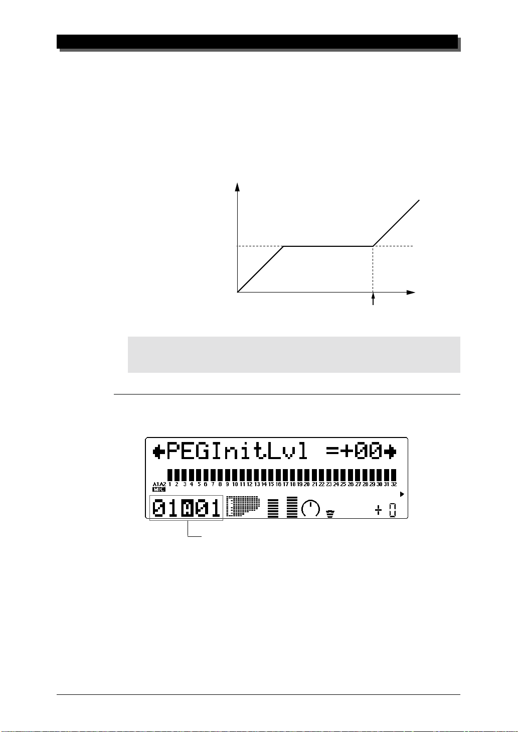
In the example Pitch EG settings below, a played note is gradually bent up to its normal pitch, and kept there as the note is held.
When the note is released, the pitch rapidly climbs up.
High
Normal
MULTI MODE
Pitch
Low
Key is released
NOTE
The Pitch EG parameters may have little or no effect, depending on the particular Voice used
and the settings made to the main EG parameters.
Time
Pitch EG Initial Level (PEGInitLvel)
Graphically shows Pitch EG Initial Level setting for each Part.
Selected Part and MIDI channel
Range: –64 … +63
Default: 0
This determines the initial pitch of the Part’s Voice, when the note is
first played. A setting of 0 corresponds to normal pitch.
49
Page 60

MULTI MODE
Pitch EG Attack Time (PEGAtakTime)
Graphically shows Pitch EG Attack Time setting for each Part.
Selected Part and MIDI channel
Range: –64 … +63
Default: 0
This determines the Attack Time of the Pitch EG, or how long it
takes for the pitch to return to normal (from the pitch value set in
Initial Level above).
Pitch EG Release Level (PEGReleLvel)
Graphically shows Pitch EG Release Level setting for each Part.
50
Selected Part and MIDI channel
Range: –64 … +63
Default: 0
This determines the final pitch of the Part’s Voice, or the pitch that
is reached after the note is released. A setting of 0 corresponds to
normal pitch.
NOTE
The Pitch EG Release Level and Time parameters may have no effect if the Voice itself does
not sustain after the note is released. (Short percussive Voices may fall into this category.)
Also make sure that the main EG Release Time is set to an appropriate value so that the sound
sustains.
Page 61

Vibrato
MULTI MODE
Pitch EG Release Time (PEGReleTime)
Graphically shows Pitch EG Release Time setting for each Part.
Selected Part and MIDI channel
Range: –64 … +63
Default: 0
This determines the Release Time of the Pitch EG, or how long it
takes for the pitch to change to the pitch value set in Release Level
above.
Part Edit Mode
Vibrato
Vibrato Rate
Vibrato Depth
Vibrato Delay
Vibrato produces a quavering, vibrating sound in the Part’s Voice, by regularly modulating the pitch. You can control the speed and depth of the Vibrato, as well as the time it takes before the Vibrato effect is applied.
Vibrato Rate
Graphically shows Vibrato Rate setting for each Part.
Selected Part and MIDI channel
51
Page 62

MULTI MODE
Range: –64 … +63
Default: 0
This determines the speed of the Vibrato effect. Higher values result
in a faster Vibrato sound.
Vibrato Depth
Graphically shows Vibrato Depth setting for each Part.
Selected Part and MIDI channel
Range: –64 … +63
Default: 0
This determines the depth of the Vibrato effect. Higher values result
in a stronger, more pronounced Vibrato sound.
Vibrato Delay
Graphically shows Vibrato Delay setting for each Part.
Selected Part and MIDI channel
Range: –64 … +63
Default: 0
This determines the delay in the onset of the Vibrato effect. Delay is
effective especially on stringed instrument Voices. For example, violin players often use delayed vibrato, especially while playing long
notes. The Delay parameter is useful in recreating this effect, producing a more natural, lifelike sound. Higher values result in a
longer Delay time.
52
Page 63

Others
MULTI MODE
Part Edit Mode
Others
Detune
Part Mode
Mono/Poly Mode
Velocity Sensitivity Depth
Velocity Sensitivity Offset
Note Limit Low
Note Limit High
Portamento Switch
Portamento Time
Velocity Limit Low
Velocity Limit High
Dry Level (VarConnect=SYS)
Pitch Bend Control
MW LFO Pitch Moduration Depth
The Others section of parameters contains miscellaneous controls, including those related to tuning, Part Mode, velocity, portamento, note range,
etc.
Detune
Graphically shows Detune setting for each Part.
Selected Part and MIDI channel
53
Page 64

MULTI MODE
Range: –12.8 … +12.7
Default: 0.0
This determines the fine tuning of the Part’s Voice.
HINT
Detune could be used to slightly detune a Voice compared to the tuning of the rest of the
Voices for a richer sound. It could also be used to detune two different Voices being played
in unison. For example if two different Parts are set to the same MIDI channel (see page 37)
and same Voice, a naturally thick chorusing effect can be obtained by slightly detuning each
Voice in opposite directions here.
Part Mode
Selected Part and MIDI channel
Height of bars indicates selected Part Mode setting for each Part. (A
single bar indicates “normal” setting.)
Settings: normal, drum, drumS1 … S4
Default: normal (Parts 1 … 9, 11 … 25, 27 … 32)
drumS1 (Part 10)
drumS3 (Part 26)
(When Sound Module mode is set to C/M, both Parts 10 and 26 are set
to drumS1.)
This determines the mode for the Part. A setting of normal allows selection of the normal instrument Voices. (See the SOUND LIST & MIDI
DATA booklet.) The drum setting allows selection of the drum kits. (See
the SOUND LIST & MIDI DATA booklet.) The drumS1 … S4 settings
are locations for storing specially programmed drum setups. These setups
can be edited by using the Drum Setup controls in the Multi Edit mode.
(See page 61.) The drum and drumS1 … S4 settings are not available in
the Performance mode.
The Part Mode settings differ depending on the Sound Module mode
selected, as described below.
54
For XG (Extended General MIDI) mode:
All settings described above are available. When normal is selected,
any of the basic or the extended set of Voices can be used for the Part.
Page 65

MULTI MODE
For TG300B mode:
The settings normal and drumS1 … S4 are available; drum cannot be
selected. When normal is selected, either the basic or the extended set
of Voices (for the TG300B mode) can be used for the Part.
For C/M mode:
The Part Mode settings are fixed in this mode and cannot be changed:
Parts 10 and 26 are set to drumS1, and all other Parts are set to nor-
mal. The MIDI Receive Channel setting for Parts 1 and 17 is set to off.
The 128 Voices of C/M Type 1 can be used for Parts 1 … 9 and 17 …
25; the 64 Voices of C/M Type 2 can be used for Parts 11 … 16 and 27
… 32.
For PFM (Performance) mode:
All four Parts are set to normal; none of the drum settings are available. Any of the basic or the extended set of Voices can be used for each
Part.
NOTE
When two or more different Parts are set to the same editable drum setup (drumS1 … S4),
any edits made to that drum setup automatically affect all those Parts. For example, when
two Parts are set to drumS1, any changes made to drumS1 affect both Parts.
Mono/Poly Mode
Height of bars indicates selected Mono/Poly Mode setting for each
Part. (A single bar indicates “mono” setting, while full height indicates
“poly.”)
Selected Part and MIDI channel
Settings: mono, poly
Default: poly
This determines whether the Part’s Voice is played monophonically
(only one note at a time) or polyphonically (up to 64 notes at a
time). This parameter is not available when the Part Mode is set to
Drum.
55
Page 66

MULTI MODE
Velocity Sensitivity Depth (VelSensDpt)
Graphically shows Velocity Sensitivity Depth setting for each Part.
Selected Part and MIDI channel
Range: 0 … 127
Default: 64
This determines the degree to which velocity affects the Part’s Voice.
Higher values make the Voice more sensitive to changes in velocity.
Velocity Sensitivity Offset (VelSensOfs)
Graphically shows Velocity Sensitivity Offset setting for each Part.
56
Selected Part and MIDI channel
Range: 0 … 127
Default: 64
This determines the volume range over which velocity affects. For
lower values, the velocity affects a volume range from minimum to
medium-loud. For higher values, velocity affects a range from medium-soft to maximum.
127
at 127
Level
0
NOTE
Depending on the Voice used, if Velocity Sensitivity Offset is set to too low of a value, the
Voice may not sound, no matter how strong the velocity.
at 64
Velocity
at 0
127
Page 67

MULTI MODE
Note Limit Parameters
The Note Limit Low and High parameters allow you to set the range
of notes for a Part’s Voice. Notes outside the range will not be
played.
HINT
Note Limit can be used to set up keyboard splits. Set two Parts to the same MIDI channel
(see page 37), but give them Note Limit settings so that one Part is played from the left side of
the keyboard and the other is played from the right.
Note Limit Low (NoteLimitL)
Graphically shows Note Limit Low setting for each Part.
Selected Part and MIDI channel
Range: C-2 … G8
Default: C-2
This determines the lowest responding note for the Part. Notes below this value will not be played.
Note Limit High (NoteLimitH)
Graphically shows Note Limit High setting for each Part.
Selected Part and MIDI channel
Range: C-2 … G8
Default: G8
This determines the highest responding note for the Part. Notes
above this value will not be played.
57
Page 68
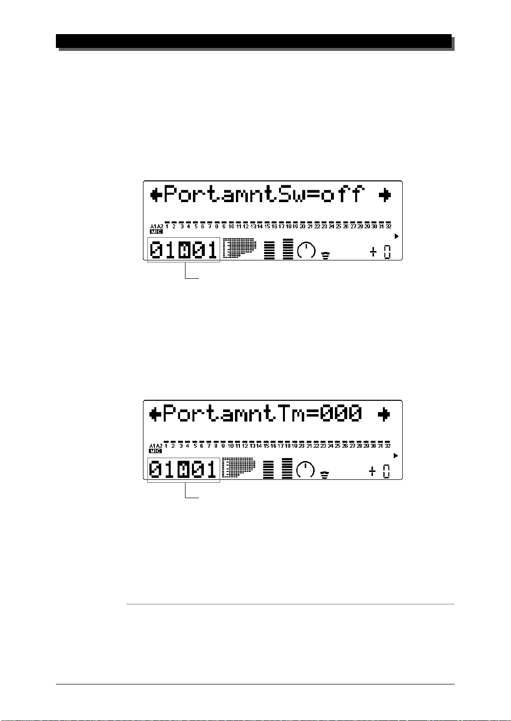
MULTI MODE
Portamento Parameters
Portamento is a function that creates a smooth pitch glide from one
note to another.
Portamento Switch (PortametSw)
Height of bars indicates selected Portamento Switch setting for each
Part. (A single bar indicates “off” setting, while full height indicates
“on.”)
Selected Part and MIDI channel
Settings: off, on
Default: off
This determines whether Portamento is on or off for the Part. (This
parameter is not available for Drum Parts.)
Portamento Time (PortametTm)
Graphically shows Portamento Time setting for each Part.
Selected Part and MIDI channel
Range: 0 … 127
Default: 0
This determines the time of the Portamento effect, or how long it
takes to glide the pitch from one note to the next. Higher values result in a longer pitch glide time. (This parameter is not available for
Drum Parts.)
Velocity Limit Parameters
The Velocity Limit Low and High parameters allow you to set the
effective velocity range for a Part’s Voice. Velocity values outside
the range will not be played. (Velocity is generally the strength at
which notes are played from a MIDI keyboard.)
58
Page 69

MULTI MODE
HINT
Velocity Limit can be used to set up velocity splits. A velocity split allows you to have one Part’s
Voice sound when you play the connected keyboard strongly, and a different Voice sound when
you play softly. Set two Parts to the same MIDI channel (see page 37), but give them different Velocity Limit settings so that one or the other sounds depending on how strongly you play the keyboard.
Velocity Limit Low (VelLimitLo)
Graphically shows Velocity Limit Low setting for each Part.
Selected Part and MIDI channel
Range: 1 … 127
Default: 1
This determines the lowest velocity value at which the Part’s Voice
will play. The higher the value, the harder the keyboard must be
played for the Voice to sound.
Velocity Limit High (VelLimitHi)
Graphically shows Velocity Limit High setting for each Part.
Selected Part and MIDI channel
Range: 1 … 127
Default: 127
This determines the highest velocity value at which the Part’s Voice
will play. The lower the value, the less strength needed (in playing
the keyboard) to get maximum volume.
no
1 127
sound
VelLimitLo VelLimitHi
no
sound
59
Page 70

MULTI MODE
Dry Level
Range: 1 … 127
Default: 127
This determines the level of the unprocessed sound of the Voice
(sound with no effect processing). This parameter is only available
when the Variation Connection parameter is set to SYS. (See page
91.)
Pitch Bend Control (PitBndCtrl)
Graphically shows Pitch Bend Control setting for each Part.
Selected Part and MIDI channel
Range: –24 … +24 semitones (+/– 2 octaves)
Default: +2
This determines the Pitch Bend range for the Part’s Voice. (Pitch Bend
is usually controlled by a pitch bend wheel on a MIDI keyboard.)
Modulation Wheel — LFO Pitch Modulation Depth
(MW LFOPMod)
Graphically shows LFO Pitch Modulation Depth setting for each Part.
Selected Part and MIDI channel
Range: 0 … 127
Default: 10
This determines how widely the pitch is modulated by the LFO (low
frequency oscillator). This is generally controlled from a modulation
wheel on a MIDI keyboard and produces a vibrato effect. The higher
the value, the deeper the pitch modulation, and hence, the more pronounced the vibrato effect.
60
Page 71

Drum Setup Controls
The Drum Setup controls allow you to make a wide variety of settings for
the drum sounds in a Drum Part. These settings include Pitch controls,
Level, Pan, effect send, filter controls and EG (Envelope Generator), among
others. Moreover, these parameters can be set to completely independent
values for each of the drum sounds in a Part.
Calling Up the Drum Setup Menu
To call up the Drum Setup menu, select a Part for which a Drum Part has
been assigned. The Drum Setup controls automatically come up in the Edit
mode. For example, if Part 10 is assigned a Drum Part, the Drum Setup
menu will appear in the main Edit menu:
MULTI MODE
Use the SELECT w buttons to select “DRUM” in the display, and
press the ENTER button.
Currently selected parameter name and value.
Currently selected note and assigned drum sound.
(Can also be selected by pressing appropriate
Use these to select the note number.
key on connected MIDI keyboard.)
Use these to select the parameter.
Use these to change the parameter value.
61
Page 72

MULTI MODE
Operation
1 Select the desired note number and its assigned drum sound with
the PART q buttons.
For a list of the available sounds and their note assignments, see
the SOUND LIST & MIDI DATA booklet.
HINT
You can also select the desired note number by simply pressing the appropriate key on a
connected MIDI keyboard.
2 Select the desired parameter with the SELECT w buttons.
Refer to the descriptions below for details on the individual parameters.
3 Change the parameter value with the VALUE q buttons.
Drum Setup Parameters
Pitch Coarse
Range: –64 … +63
This determines the coarse pitch setting of the selected drum sound.
This parameter is only available when the Part Mode has been set to
DrumS1 … S4. (See page 54.)
62
Pitch Fine
Range: –64 … +63
This determines the fine pitch setting of the selected drum sound.
Level
Range: 0 … 127
This determines the volume of the selected drum sound.
Pan
Settings: Rnd (Random), L63 … C … R63
This determines the stereo position of the selected drum sound. A
setting of “Rnd” (Random) randomly assigns the drum to a pan position. This is useful when you want to have different drums sound
from different random parts of the stereo image.
Reverb Send (Rev Send)
Range: 0 … 127
This determines the level of the selected drum sound that is sent to
the Reverb effect. A value of 0 results in a completely “dry” drum
sound, no matter how much Reverb is applied to the Drum Part.
 Loading...