

Page 1
Owner’s Manual
Bedienungsanleitung
Mode d’emploi
Page 2

SPECIAL MESSAGE SECTION
This product utilizes batteries or an external power
supply (adapter). DO NOT connect this product to
any power supply or adapter other than one described in the manual, on the name plate, or specifically recommended by Yamaha.
WARNING: Do not place this product in a position
where anyone could walk on, trip over ,or roll
anything over power or connecting cords of any kind.
The use of an extension cord is not recommended!
IF you must use an extension cord, the minimum
wire size for a 25' cord (or less ) is 18 AWG. NOTE:
The smaller the AWG number ,the larger the current
handling capacity. For longer extension cords,
consult a local electrician.
This product should be used only with the components supplied or; a cart, rack, or stand that is
recommended by Yamaha. If a cart, etc., is used,
please observe all safety markings and instructions
that accompany the accessory product.
SPECIFICATIONS SUBJECT TO CHANGE:
The information contained in this manual is believed to be correct at the time of printing. However,
Yamaha reserves the right to change or modify any
of the specifications without notice or obligation to
update existing units.
This product, either alone or in combination with an
amplifier and headphones or speaker/s, may be
capable of producing sound levels that could cause
permanent hearing loss. DO NOT operate for long
periods of time at a high volume level or at a level
that is uncomfortable. If you experience any hearing loss or ringing in the ears, you should consult
an audiologist.
IMPORTANT: The louder the sound, the shorter
the time period before damage occurs.
Some Yamaha products may have benches and / or
accessory mounting fixtures that are either supplied
with the product or as optional accessories. Some of
these items are designed to be dealer assembled or
installed. Please make sure that benches are stable
and any optional fixtures (where applicable) are well
secured BEFORE using.
Benches supplied by Yamaha are designed for
seating only. No other uses are recommended.
NOTICE:
Service charges incurred due to a lack of knowledge relating to how a function or effect works
(when the unit is operating as designed) are not
covered by the manufacturer’s warranty, and are
therefore the owners responsibility. Please study
this manual carefully and consult your dealer
before requesting service.
ENVIRONMENTAL ISSUES:
Yamaha strives to produce products that are both
user safe and environmentally friendly. We sin-
cerely believe that our products and the production
methods used to produce them, meet these goals.
In keeping with both the letter and the spirit of the
law, we want you to be aware of the following:
Battery Notice:
This product MAY contain a small non-rechargeable battery which (if applicable) is soldered in
place. The average life span of this type of battery
is approximately five years. When replacement
becomes necessary, contact a qualified service
representative to perform the replacement.
This product may also use “household” type batteries. Some of these may be rechargeable. Make
sure that the battery being charged is a rechargeable type and that the charger is intended for the
battery being charged.
When installing batteries, do not mix batteries with
new, or with batteries of a different type. Batteries
MUST be installed correctly. Mismatches or incorrect installation may result in overheating and
battery case rupture.
Warning:
Do not attempt to disassemble, or incinerate any
battery. Keep all batteries away from children.
Dispose of used batteries promptly and as regulated by the laws in your area. Note: Check with
any retailer of household type batteries in your area
for battery disposal information.
Disposal Notice:
Should this product become damaged beyond
repair, or for some reason its useful life is considered to be at an end, please observe all local,
state, and federal regulations that relate to the
disposal of products that contain lead, batteries,
plastics, etc. If your dealer is unable to assist you,
please contact Yamaha directly.
NAME PLATE LOCATION:
The name plate is located on the bottom of the
product. The model number, serial number, power
requirements, etc., are located on this plate. You
should record the model number, serial number,
and the date of purchase in the spaces provided
below and retain this manual as a permanent
record of your purchase.
Model
Serial No.
Purchase Date
2
92-BP (bottom)
PLEASE KEEP THIS MANUAL
Page 3
PRECAUTIONS
PLEASE READ CAREFULLY BEFORE PROCEEDING
* Please keep these precautions in a safe place for future reference.
WARNING
Always follow the basic precautions listed below to avoid the possibility of serious injury or even death from
electrical shock, short-circuiting, damages, fire or other hazards. These precautions include, but are not limited
to, the following:
• Do not open the instrument or attempt to disassemble the
internal parts or modify them in any way. The instrument
contains no user-serviceable parts. If it should appear to be
malfunctioning, discontinue use immediately and have it
inspected by qualified Yamaha service personnel.
• Do not expose the instrument to rain, use it near water or in
damp or wet conditions, or place containers on it containing
liquids which might spill into any openings.
• If the AC adaptor cord or plug becomes frayed or damaged, or
if there is a sudden loss of sound during use of the instrument,
or if any unusual smells or smoke should appear to be caused
CAUTION
Always follow the basic precautions listed below to avoid the possibility of physical injury to you or others, or
damage to the instrument or other property. These precautions include, but are not limited to, the following:
• Do not place the AC adaptor cord near heat sources such as
heaters or radiators, and do not excessively bend or otherwise
damage the cord, place heavy objects on it, or place it in a
position where anyone could walk on, trip over, or roll anything
over it.
• When removing the electric plug from the instrument or an
outlet, always hold the plug itself and not the cord.
• Do not connect the instrument to an electrical outlet using a
multiple-connector. Doing so can result in lower sound quality,
or possibly cause overheating in the outlet.
• Unplug the AC power adaptor when not using the instrument,
or during electrical storms.
• Always make sure all batteries are inserted in conformity with
the +/- polarity markings. Failure to do so might result in
overheating, fire, or battery fluid leakage.
• Always replace all batteries at the same time. Do not use new
batteries together with old ones. Also, do not mix battery types,
such as alkaline batteries with manganese batteries, or
batteries from different makers, or different types of batteries
from the same maker, since this can cause overheating, fire,
or battery fluid leakage.
• Do not dispose of batteries in fire.
• Do not attempt to recharge batteries that are not intended to
be charged.
• If the instrument is not to be in use for a long time, remove the
batteries from it, in order to prevent possible fluid leakage from
the battery.
• Keep batteries away from children.
• Before connecting the instrument to other electronic
components, turn off the power for all components. Before
turning the power on or off for all components, set all volume
levels to minimum.
• Do not expose the instrument to excessive dust or vibrations,
(4)-3
by it, immediately turn off the power switch, disconnect the
adaptor plug from the outlet, and have the instrument inspected
by qualified Yamaha service personnel.
• Use the specified adaptor (PA-3B or an equivalent
recommended by Yamaha) only. Using the wrong adaptor can
result in damage to the instrument or overheating.
• Before cleaning the instrument, always remove the electric
plug from the outlet. Never insert or remove an electric plug
with wet hands.
• Check the electric plug periodically and remove any dirt or dust
which may have accumulated on it.
or extreme cold or heat (such as in direct sunlight, near a heater,
or in a car during the day) to prevent the possibility of panel
disfiguration or damage to the internal components.
• Do not use the instrument near other electrical products such
as televisions, radios, or speakers, since this might cause
interference which can affect proper operation of the other
products.
• Do not place the instrument in an unstable position where it
might accidentally fall over.
• Before moving the instrument, remove all connected adaptor
and other cables.
• When cleaning the instrument, use a soft, dry cloth. Do not
use paint thinners, solvents, cleaning fluids, or chemicalimpregnated wiping cloths. Also, do not place vinyl, plastic or
rubber objects on the instrument, since this might discolor the
panel or keyboard.
• Do not rest your weight on, or place heavy objects on the
instrument, and do not use excessive force on the buttons,
switches or connectors.
• Do not operate the instrument for a long period of time at a
high or uncomfortable volume level, since this can cause
permanent hearing loss. If you experience any hearing loss or
ringing in the ears, consult a physician.
■SAVING USER DATA
• Save all data to an external device such as the Yamaha MIDI
Data Filer MDF3, in order to help prevent the loss of important
data due to a malfunction or user operating error.
Yamaha cannot be held responsible for damage caused by
improper use or modifications to the instrument, or data that is
lost or destroyed.
Always turn the power off when the instrument is not in use.
Make sure to discard used batteries according to local regulations.
English
3
Page 4

Welcome to the MU15
Congratulations and thank you for purchasing the Yamaha MU15 Tone Generator!
The MU15 an advanced, yet easy-to-use tone generator providing exceptionally
high-quality Voices, built-in effects, XG format and General MIDI (GM) compatibility, plus direct connection to computer — all in a highly compact and
portable package.
With the built-in host computer interface and MIDI terminals, the MU15 is ideal
for any computer music system — from connection to a simple laptop to
integration in a complete MIDI studio. It even features a two-octave keyboard
(with adjustable ten-octave range), allowing you to play the internal Voices and
enter notes to a connected sequencer. Since it’s compatible with Yamaha’s
powerful XG format, it lets you faithfully and easily playback any XG or GM
song data.
The MU15 also features 16-Part multi-timbral capacity and full 32-note polyphony for playback of even very sophisticated, multi-part song data. Three
independent digital effect sections give you enormous versatility in “sweetening” the sound. What’s more, the MU15 provides a host of comprehensive
editing tools for getting just the sound you need.
4
Page 5
GM System Level 1
“GM System Level 1” is a standard specification that
defines the arrangement of voices in a tone generator
and its MIDI functionality, ensuring that data can be
played back with substantially the same sounds on any
GM-compatible tone generator, regardless of its manufacturer or model.
Tone generators and song data that meet the “GM
System Level 1” bear this GM logo.
XG
“XG” is a tone generator format that expands the voice
arrangement of the “GM System Level 1” specification
to meet the ever-increasing demands of today’s computer peripheral environment, providing richer expressive power while maintaining upward compatibility of
data. “XG” greatly expands “GM System Level 1” by
defining the ways in which voices are expanded or
edited and the structure and type of effects.
When commercially available song data bearing the XG
logo is played back on a tone generator which bears the
XG logo, you will enjoy a full musical experience that
includes unlimited expansion voices and effect functions.
English
Your MU15 package should include the items listed below. Make sure that you
have them all.
• MU15
• Owner’s Manual
5
Page 6

Table of Contents
How to Use This Manual .......................................................................................... 8
The MU15 — What It Is and What It Can Do ........................................................ 10
What It Is... ................................................................................................... 10
What It Can Do... .......................................................................................... 10
About General MIDI (GM) ............................................................................. 12
About XG ...................................................................................................... 12
Panel Controls and Terminals ................................................................................ 13
Guided Tour 17
Setting Up Your MU15............................................................................................ 17
What You’ll Need .......................................................................................... 17
Power Supply ............................................................................................... 18
Using a Power Adaptor .................................................................... 18
Using Batteries ................................................................................ 19
When to Replace the Batteries ........................................................ 19
Making the Connections ............................................................................... 20
Powering Up ................................................................................................. 21
Playing the MU15 .................................................................................................... 22
Playing the Keyboard .................................................................................... 22
Playing the Demo Song ................................................................................ 22
Selecting Voices ........................................................................................... 24
About Parts, Voices, and Banks .................................................................... 24
Selecting Parts .............................................................................................. 26
Selecting Banks ............................................................................................ 27
Playing Drum Voices ..................................................................................... 28
Changing the Octave Setting ........................................................................ 29
Editing a Part ................................................................................................ 30
Changing the Note Shift and Volume Settings ................................ 30
Soloing and Muting Parts ............................................................................. 31
Using the Effects .......................................................................................... 32
Using Reverb and Chorus ................................................................ 32
Using the Variation Effects .............................................................. 33
Using the MU15 with a Computer/Sequencer ..................................................... 36
Setting Up ..................................................................................................... 36
Playing Song Data ......................................................................................... 40
MIDI/Computer Connecting Cables .............................................................. 41
Reference 42
Function Tree ........................................................................................................... 42
Play Mode ................................................................................................................ 43
Sound Module Mode .................................................................................... 43
Edit Mode ................................................................................................................. 44
Part Controls ................................................................................................. 45
Volume ............................................................................................. 46
Pan ................................................................................................... 47
Note Shift ......................................................................................... 47
Solo .................................................................................................. 48
Mute ................................................................................................ 49
6
Page 7

Table of Contents
• Filter Parameters — Cutoff Frequency and Resonance ............. 50
Cutoff Frequency ............................................................................. 50
Resonance ....................................................................................... 51
• EG (Envelope Generator) Parameters — Attack Time and
Release Time .................................................................................. 52
Attack Time ...................................................................................... 53
Release Time ................................................................................... 53
• Vibrato Parameters — Rate, Depth, and Delay ........................... 54
Vibrato Rate ..................................................................................... 54
Vibrato Depth ................................................................................... 54
Vibrato Delay .................................................................................... 55
Effect Controls .............................................................................................. 56
• Reverb Parameters ........................................................................ 56
Reverb Send Level ........................................................................... 57
Reverb Type ..................................................................................... 57
• Chorus Parameters ........................................................................ 58
Chorus Type ..................................................................................... 58
Chorus Send Level ........................................................................... 59
• Variation Parameters ..................................................................... 59
Variation Connection ........................................................................ 60
Variation Type ................................................................................... 60
Variation Send Level ........................................................................ 61
Dry Level .......................................................................................... 62
Utility Controls .............................................................................................. 63
Master Tune..................................................................................... 63
Velocity ............................................................................................ 64
Local Control .................................................................................... 64
Dump Out ........................................................................................ 65
Initialize All ....................................................................................... 68
English
Appendix 69
Troubleshooting ...................................................................................................... 69
Error Messages ........................................................................................................ 71
Specifications .......................................................................................................... 72
Index ......................................................................................................................... 73
Sound List & MIDI Data 75
XG Normal Voice List .............................................................................................. 76
TG300B Normal Voice List ...................................................................................... 78
XG Drum Voice List (Drum Map) ........................................................................... 80
TG300B Drum Voice List (Drum Map) ................................................................... 82
Effect Type List ........................................................................................................ 84
Effect Parameter List............................................................................................... 85
Effect Data Assign Table ......................................................................................... 90
MIDI Data Format .................................................................................................... 91
MIDI Implementation Chart .................................................................................. 108
7
Page 8

How to Use This Manual
How to Use This Manual
You are probably eager to try out your new MU15 Tone Generator right away
and hear what it can do, rather than have to read through a lot of instructions
before you can even get a sound out of it. Since the MU15 is so easy to use,
you could play it right “out of the box” without even having to glance at the
manual. However, to get the most out of your MU15 and to avoid damaging it,
we strongly suggest that you take time to read the sections introduced below.
The structure of the manual is very straightforward. You can approach it in a
linear manner, reading through from beginning to end, or on an “on-demand”
basis, going directly to the information as you need it.
1) Precautions
Read this section very carefully for important information on how to
care for your new MU15, how to avoid damaging it, and how to
ensure long-term, reliable operation.
2) The MU15 — What It Is and What It Can Do
This briefly provides an overview of the functions and features of the
MU15 and offers some important hints on how you can use it
effectively.
3) Panel Controls and Terminals
This section introduces you to the panel controls and terminals of the
MU15, and where applicable provides convenient page references
for more information.
4) Guided Tour
This is perhaps the most important and valuable section of the
manual. It gets you started using your new MU15, helping you set
up the instrument, integrate it into your music system, and play it. It
also introduces you to virtually all of the important functions and
features. The hands-on experience that you gain in this section will
help you quickly master the instrument and aid you in navigating the
more detailed sections of the manual.
8
Page 9

How to Use This Manual
5) Reference
Once you’re familiar with everything above, lightly go over this
comprehensive guide to all editing functions. You won’t need (or
want) to read everything at once, but it is there for you to refer to
when you need information about a certain feature or function.
6) Appendix
Use the sections in the Appendix as necessary. For example, the
Index will come in handy when you need to quickly find information
on a specific topic. Other sections, such as Troubleshooting and
Error Messages, provide additional useful information.
7) Sound List & MIDI Data
This section features lists of the Voices, drum sounds, effect types
and parameters, as well as details on all relevant MIDI messages and
data.
NOTE
• The illustrations and LCD screens as shown in this owner’s manual are
for instructional purposes only, and may appear somewhat different
from those on your instrument.
English
9
Page 10

The MU15 — What It Is and What It Can Do
The MU15 — What It Is and
What It Can Do
What It Is...
The MU15 is a compact, highly portable and easy-to-use tone
generator. It features XG compatibility with a stunning variety of 480
XG Voices (including 128 GM Voices) and 11 Drum Voices (with
Drum and SFX kits).* The MU15 has 32-Voice polyphony and is 16Part multi-timbral. In other words, the MU15 has 16 different Parts,
each with its own Voice, so that up to 16 different Voices can be
sounded simultaneously.
With the built-in two-octave keyboard, you can play any of the Voices
directly from the MU15 itself. Or you can play them from a connected MIDI keyboard. In addition, the MU15 also has a TO HOST
terminal for easy interfacing with a computer, allowing you to play
the Voices using your favorite music software. This is where the
advanced multi-timbral capabilities come in, letting you play up to 16
different Voices at the same time.
10
* The MU15 has a total of 676 different Voices. A separate
TG300B mode (page 43) features 579 Voices, some of which are
diiferent than the XG set.
What It Can Do...
Here are a few ideas on how you can use the MU15. The list below
is not comprehensive, but is meant to be a general guide to the
possibilities and provide a starting point or springboard for your own
creative ideas and explorations.
Carry It With You
If you have a laptop computer (and sequencing software), simply
connect the MU15, plug in some headphones and you’ve got a
complete music making system that’s ready to go wherever you go.
Page 11

The MU15 — What It Is and What It Can Do
Use it for composing, arranging, practicing or making/playing demos
for your band.
Perform With It
Bring it with you to a gig — as long as there’s a MIDI keyboard on
stage, you can use the high-quality sounds of MU15 in your performance.
Multimedia
Since it’s portable and compatible with General MIDI, the MU15 is a
natural for multimedia applications. Bring it with you to a presentation — since the computer interface is built-in to the MU15, it hooks
up instantly and easily to the computer’s serial port without the need
for any other equipment.
Using With MIDI Keyboard
Use the MU15 as supplementary tone generator with your MIDI
keyboard and play the Voices of both instruments in a layer together.
Or, if your keyboard has the capability, program a “split” so that the
notes you play on the right side of the keyboard play only the Voices
of the MU15.
English
Using With Other MIDI Controllers
Even if you’re not a keyboard player, you can still play the MU15 with
other types of MIDI controllers. For example, use a MIDI percussion
controller to play the drum and percussion sounds of the MU15.
Guitar controllers (such as the Yamaha G50) or wind controllers (such
as the Yamaha WX5) are also available for players of those instruments.
Home Studio Setup
The MU15 integrates easily into any existing setup. If you have a
MIDI keyboard, computer and sequencing software, the MU15 with
its high-quality Voices and multi-timbral capabilities can expand your
home studio system.
11
Page 12

The MU15 — What It Is and What It Can Do
About General MIDI (GM)
General MIDI (GM) is a new addition to the worldwide MIDI standard. MIDI, as you know, stands for Musical Instrument Digital
Interface, and makes it possible for various electronic musical
instruments and other devices to “communicate” with each other.
For example, by connecting a sequencer to the MU15’s MIDI IN
terminal, you could play back a song on the sequencer using the
Voices of the MU15.
So, where does GM fit in all of this? One of the most important
features of General MIDI is in the standardization of Voices. This
means that a song recorded in the GM standard can be played back
on any GM-compatible tone generator and sound just as the composer intended. For example, if there is an alto sax solo in the song,
it will be played by an alto sax Voice on the General MIDI tone
generator (and not by a tuba or harpsichord!). Since the MU15 is
fully GM-compatible, you can take advantage of the vast wealth of
musical material recorded in that format.
About XG
The Yamaha XG format is an extension of General MIDI, and provides a number of significant improvements and enhancements. XGcompatible song data takes advantage of the expanded Voice set,
extensive MIDI control and built-in effects of the MU15 (as well as
other MU-series instruments).
12
To get the most out of XG and your MU15, we recommend using
XG-compatible instruments and software. For example, the Yamaha
CBX-K2 keyboard lets you dynamically control a variety of parameters in real time while you play. The XGworks sequencer software
not only lets you playback GM- or XG-compatible song data, it lets
you record your own songs — and gives you enormously powerful
and easy-to-use editing tools for adjusting detailed settings of the
MU15 that are unavailable with the panel controls.
Page 13
Panel Controls and Terminals
Panel Controls and Terminals
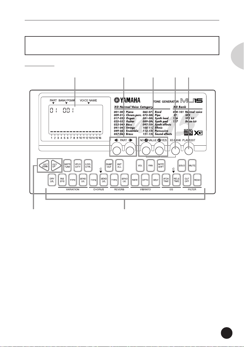
Front Panel
q w e r t
GrandPno
y u
English
q Display
In the Play mode, this shows the Part number, the currently selected
program number and Voice name for the Part. It also shows the
octave setting (when set to a value other than normal) and acts as a
“level meter,” showing the volume for each Part as it is played.
When the XG BANK button is held down, it shows the currently
selected Bank number and Voice name.
In the Edit mode, this shows the relevant values and, where applicable, a graphic display of the set values.
13
Page 14
Panel Controls and Terminals
w PART buttons ( , )
For selecting the desired Part. (In some of the Edit functions, these
may not be available.) Hold down either button to rapidly advance
through the values.
e VALUE buttons ( /NO, /YES)
For changing the value of the selected function or parameter. In the
Play mode, these are used to change the Voice number (or Bank
number) at the selected Part. In the Edit mode, these are used to
change the current function’s value. Hold down either button to
rapidly advance through the values. For even faster editing, simultaneously hold down one button, and then press (or hold down) the
other. For example, to rapidly decrease the value, simultaneously
hold down the
/NO button and press the /YES button.
r XG BANK button
For selecting or confirming the desired Voice Bank (pages 26, 27).
To select Banks, simultaneously hold down this button and press
one of the VALUE buttons. To confirm the currently selected Bank,
simply press this button.
14
t PLAY/EDIT button
For switching between the Play and Edit modes, and (when held
down) for selecting the desired Edit mode parameter. (Page 30.)
y OCTAVE DOWN and OCTAVE UP buttons
For changing the octave transposition of the MU15’s keyboard.
(Page 29.)
u Keyboard
This two-octave keyboard is used to play the Voices of the MU15. It
can also be used to enter notes to a connected sequencer or
computer. (Page 22.)
The keys are also used to select Edit mode parameters (the names
of which are printed on the buttons). (Page 44.)
Page 15
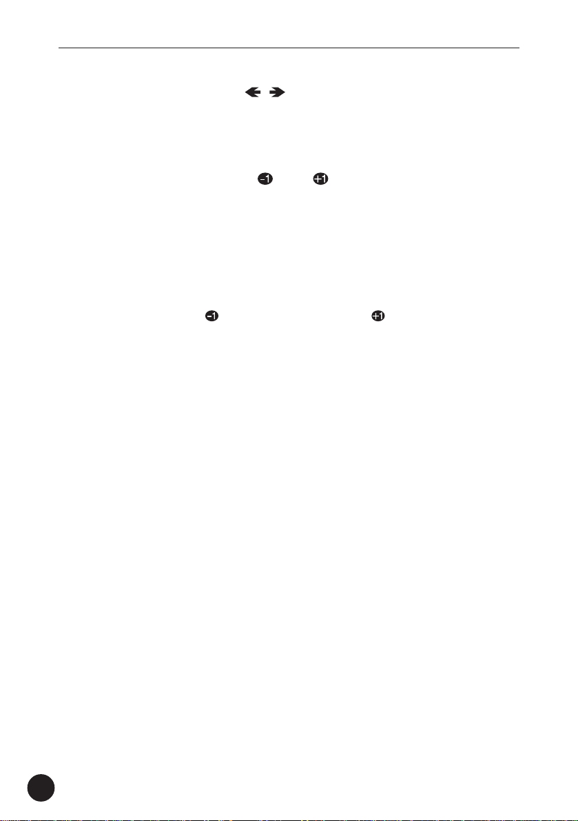
Rear Panel
Panel Controls and Terminals
English
q w e r t
q MIDI OUT and MIDI IN terminals
For connection to other MIDI devices, such as a MIDI keyboard, tone
generator, sequencer, or to a computer that has a MIDI interface.
(Pages 20, 39.)
w HOST SELECT switch
For selecting the type of connected device (computer or MIDI
device). (Page 37.)
e TO HOST terminal
For connection to a host computer that does not have a MIDI
interface. (Page 37.)
r DC IN jack
For connection to the AC power adaptor (PA-3B).
t ON/ STANDBY switch
For turning the power on and off.
15
Page 16
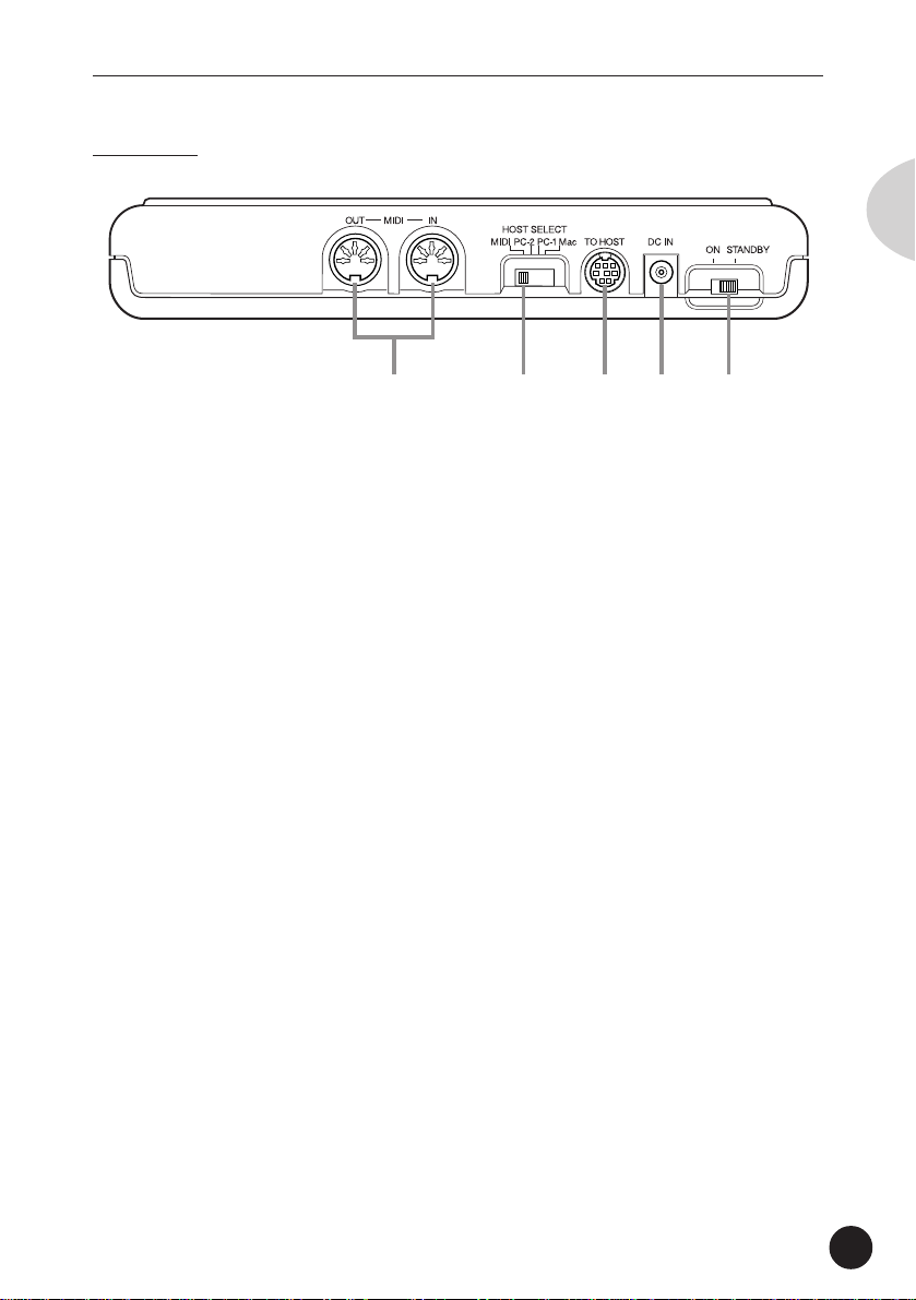
Side Panel
Panel Controls and Terminals
q w
q VOLUME control
For adjusting the overall level of the MU15.
w LINE OUT/PHONES jack
For connection to an amplifier/speaker system or a set of stereo
headphones.
16
Page 17

Guided Tour
Guided Tour
When using your MU15 for the first time, read
through this short section of the manual. It guides you
step-by-step in using many of the basic operations: setting
the instrument up, connecting it properly to other equipment, and — most importantly — playing it. It also introduces you to most of the other, advanced features and
operations of the instrument — enabling you to quickly
and effectively get the most out of your new MU15.
Setting Up Your MU15
Since the MU15 has a built-in keyboard, you could use it with nothing more
than a set of batteries and a proper set of stereo headphones. It can also be
used effectively with a computer in a “desktop music” system.
English
In this section, however, you’ll learn how to connect the MU15 in a basic
system with a MIDI keyboard and an external amplifier/speaker system. (For
basic information on MIDI and its applications, see page 91.)
What You’ll Need
• The MU15 and a proper power supply (either an AC adaptor or
batteries).
• A MIDI keyboard, electronic piano, or any instrument that can
output MIDI data.
• An amplifier speaker system, preferably stereo. Alternately, you
can use a set of stereo headphones.
• Audio connecting cables.
• A MIDI cable.
17
Page 18
Setting Up Your MU15
Power Supply
Although the MU15 will run either from an optional AC adaptor or batteries,
Yamaha recommends use of an AC adaptor whenever possible. Moreover, an
AC adaptor is more environmentally friendly than batteries and does not
deplete resources.
CAUTION
• Before making any connections, make sure that all equipment to be connected is
turned off.
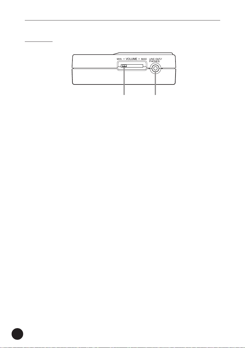
Using a Power Adaptor
Connect one end of the power adaptor (Yamaha PA-3B) to the DC IN
jack on the rear panel, and the other end to a suitable electrical
outlet.
18
WARNING
• Do not attempt to use an AC adaptor other than the PA-3B. The use of
an incompatible adaptor may result in irreparable damage to the MU15,
and even pose a serious shock hazard.
CAUTION
• When connecting the AC power adaptor, first make sure that the MU15
is turned off (set to STANDBY). Next, connect one end of the power
adaptor to the DC IN jack on the MU15, and connect the other end to
an appropriate AC outlet.
• The MU15 has a convenient data backup feature that maintains any
changes you’ve made to the settings, even when the power is turned
off. However, removing the batteries or disconnecting the AC adaptor
automatically clears the data and restores the factory defaults. To save
your important data, use the Dump Out function (page 65).
Page 19
Setting Up Your MU15
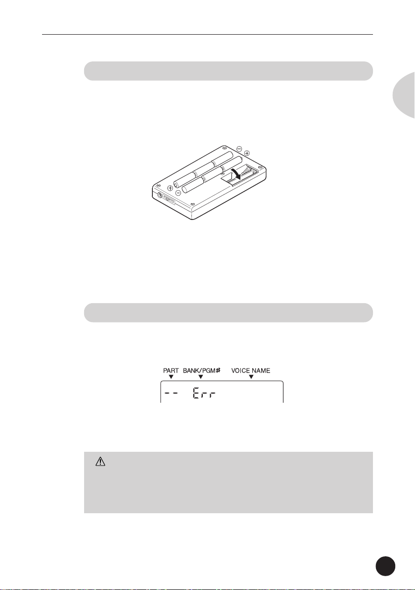
Using Batteries
To use the MU15 on battery power, insert six 1.5V AA size (SUM-3,
R-6 or equivalent) manganese or alkaline batteries in the battery
compartment. Make sure to follow the polarity indications on the
bottom case (and as shown below).
Securely replace the battery compartment cover when done installing the batteries.
When to Replace the Batteries
When the battery power runs too low to operate the MU15, the
sound may become distorted and the following display will appear:
English
Battery
When this happens, replace all batteries with a complete set of six
new batteries of the same type.
CAUTION
• NEVER mix old and new batteries or different types of batteries! Also,
to prevent possible damage due to battery leakage, remove the
batteries from the instrument if it is not to be used for an extended
period of time.
19
Page 20
Setting Up Your MU15
Making the Connections
CAUTION
• Before making any connections, turn all related equipment off, and make sure the
MU15’s power adaptor is not connected to an electrical outlet.
Operation
Z Connect the MIDI cable.
Connect the MIDI OUT terminal of the MIDI keyboard to the MIDI IN
terminal of the MU15 (as shown in the illustration).
X Connect the audio cables.
If you are using an external sound system, connect the LINE OUT/
PHONES jack on the side of the MU15 to the appropriate inputs of
the sound system (as shown). Use a stereo mini-plug to dual RCA
pin “Y” cable (available at many audio and musical instrument
dealers).
If you are using stereo headphones (with a stereo mini-plug), connect them to the same LINE OUT/PHONES jack on the MU15.
20
C Set the HOST SELECT switch.
Set this rear panel to “MIDI” (as shown).
MIDI IN
GrandPno
MIDI OUT
MIDI keyboard
LINE OUT/
PHONES
MIDI
Amplifier/speaker system
Page 21

Setting Up Your MU15
Powering Up
Admittedly, this is a simple operation, but you should be careful to follow the
instructions below to avoid possible damage to your equipment and speakers.
Operation
Z Turn on the power of your MIDI keyboard.
X Turn down all volume controls.
This includes the MU15 and any connected equipment.
C Turn on the power of the MU15.
Set the ON/STANDBY switch to “ON.”
V Turn on the amplifier/speaker system.
B Set the volume controls.
First, set the volume control on the MU15 to about midway or
higher, and then set the volume on the amplifier to a suitable level.
Powering Down
English
When you turn the power off, make sure to do it in the following
order, to prevent possible speaker damage:
1) Amplifier/speaker system
2) MU15
3) Any other connected equipment (MIDI keyboard, etc.)
CAUTION
• Even when the switch is in the “STANDBY” position, electricity is still
flowing to the instrument at the minimum level. When you are not
using the MU15, make sure you unplug the AC power adaptor from the
wall AC outlet and remove the batteries from the MU15.
21
Page 22
Playing the MU15
Playing the MU15
Playing the Keyboard
If you’ve set up everything properly in the instructions above, you can now play
the MU15. Press the keys on the built-in keyboard to hear the currently
selected Voice.
Try also playing the connected MIDI keyboard. As long as the keyboard is
sending MIDI data, it doesn’t matter what the MIDI channel setting is — at
least one of the Voices on the MU15 will sound. (For more information on
MIDI, see page 91.)
Playing the Demo Song
To get a taste of what is possible with the MU15, try playing the built-in Demo
Song. This showcases the high-quality Voices and the AWM tone generation
system of the MU15.
Operation
Z Simultaneously hold down the PLAY/EDIT button and
press the VALUE
22
/YES button.
DemoSong
“DemoSong” and “PressYES”
alternately appear in the display.
Page 23
Playing the MU15
X Start the song by pressing the VALUE /YES button.
The Demo Song starts playing immediately and repeats indefinitely
until stopped (in step #3 below). Playback of the individual Parts of
the song is shown graphically by the “level meter” bars in the
display.
CAUTION
• Once you play the demo song, any edits that you’ve made to the MU15
will be cleared (with the exception of the Velocity, Local Control and
Octave settings). To save your important data, use the Dump Out
function (page 65).
NOTE
• During Demo Song playback, all panel controls (except the VALUE /
NO button and the VOLUME control) cannot be used.
English
C To stop playback of the song, press the VALUE /NO
button.
V To exit from the Demo Song function and return to the
Play mode, press the PLAY/EDIT button or the VALUE
/NO button.
*Demo Song Credit
Programmed and Composed by Gigbag (Presto Inc.)
23
Page 24
Playing the MU15
Selecting Voices
The MU15 has a total of 676 different instrument Voices. Here, we’ll select a
different Voice for playing.
Each Voice is numbered, and there are 128 Voices from which you can immediately select. (We’ll see how to select Voices outside of these 128 later.)
Operation
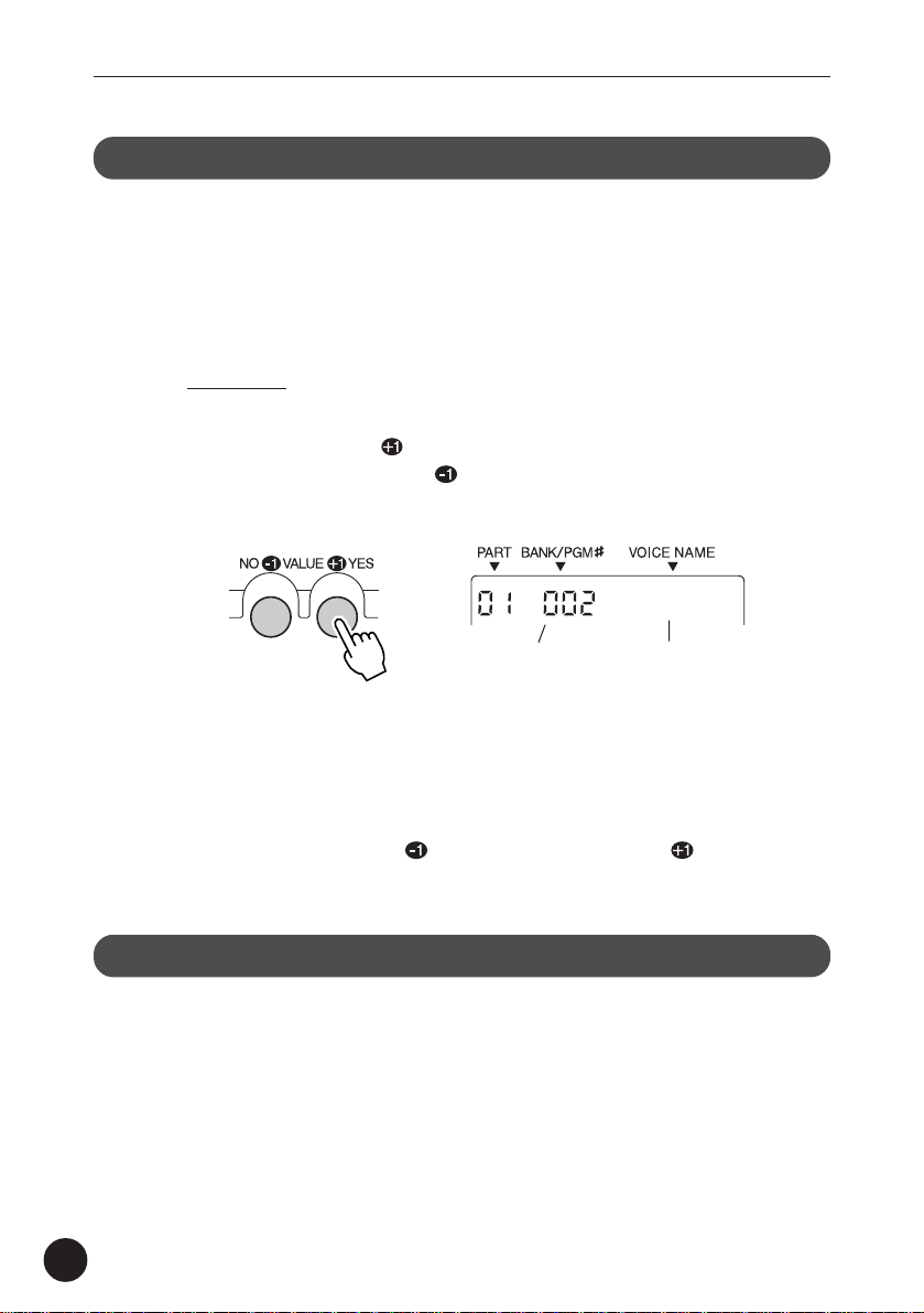
Use the VALUE buttons.
Pressing the VALUE /YES button steps up through Voice numbers
while pressing the VALUE
numbers.
/NO button steps down through the
BritePno
Voice nameVoice number
Hold either button down to move rapidly through the numbers in the
selected direction. To move even more quickly through the numbers, simultaneously hold down one button, and then press (or hold
down) the other. For example, to rapidly decrease the value, simultaneously hold down the
/NO button and press the /YES button.
About Parts, Voices, and Banks
Before we go on to the next section, a little explanation about the organization
of the MU15 is needed. Here, you’ll learn about Parts, Voices, and Banks —
three important concepts around which the sounds of the MU15 are organized.
24
Page 25
Playing the MU15
Voices
As mentioned in the section “The MU15 — What It Is and What It
Can Do,” the MU15 is capable of playing sixteen different instrument sounds at the same time. Each instrument sound is called a
“Voice,” and the MU15 has 676 different Normal Voices, as well as
21 Drum Voices.
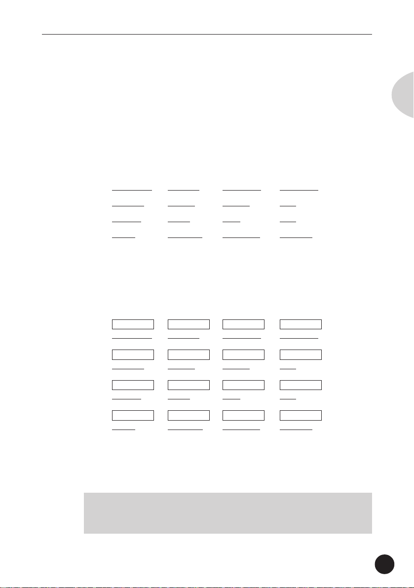
Let’s say, for example, you have a song in which you want to use the
following sixteen Voices:
Grand Piano Pick Bass Steel Guitar Rock Organ
Tenor Sax Alto Sax Trumpet Flute
Marimba Drums Violin Cello
Strings Warm Pad Sweep Pad Saw Lead
Parts
For these Voices to be used simultaneously, they must be assigned
to different “Parts.” These correspond exactly to the parts of a song
or the elements of a band, such as bass, guitar, and drums.
English
Part 1 Part 2 Part 3 Part 4
Grand Piano Pick Bass Steel Guitar Rock Organ
Part 5 Part 6 Part 7 Part 8
Tenor Sax Alto Sax Trumpet Flute
Part 9 Part 10 Part 11 Part 12
Marimba Drums Violin Cello
Part 13 Part 14 Part 15 Part 16
Strings Warm Pad Sweep Pad Saw Lead
Obviously, each Part can have its own Voice setting, but it can also
have independent settings for other aspects of the sound as well, as
we’ll see later.
NOTE
• Part 10 is normally reserved for Drum Voices, although this can be
changed. (Page 28.)
25
Page 26
Playing the MU15
Banks
As you learned in “Selecting Voices” above, each Voice is numbered,
and there are 128 of them from which you can select. These 128
Voices make up a Voice “Bank.” The MU15 has many Banks, each
of which contain 128 Voices. By selecting a different Bank, you can
select different Voices — any of the 676 Voices available on the
MU15.
Now, let’s go on to the next sections and see how to select different
Parts, and how to select Voices on the other Banks.
Selecting Parts
In “Selecting Voices” above, you learned how to select a Voice. Here, you’ll
see how to select a different Part and select a different Voice for that Part.
Operation
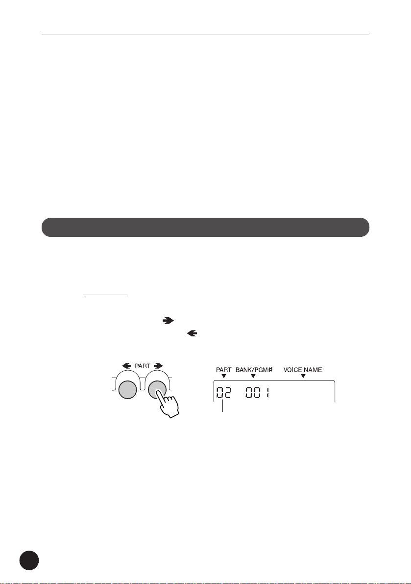
Z Select the desired Part by using the PART buttons.
Pressing the PART button steps up through the Part numbers
while pressing the PART
bers.
button steps down through the num-
26
GrandPno
Part number
Hold either button down to move rapidly through the numbers in the
selected direction.
X Select a Voice for the current Part.
Do this in the normal way, by using the VALUE buttons.
Page 27
Playing the MU15
Selecting Banks
As you learned in “About Parts, Voices, and Banks” above, the MU15’s 676
Voices are organized into Banks of 128 Voices each. Here, we’ll see how to
select Voices of different Banks.
Operation
Z Select the desired Part.
Do this in the normal way, by using the PART buttons.
X Select the desired Voice.
Do this in the normal way, by using the VALUE buttons.
In general, the Voice Banks feature variations on the basic Voices —
for example, the “PercOrgn” Voice has several similar sounding
organ Voices at the same Voice number, but in different Banks.
That’s why it’s a good idea to decide which type of Voice you want,
and then call up different Banks to select a specific Voice variation.
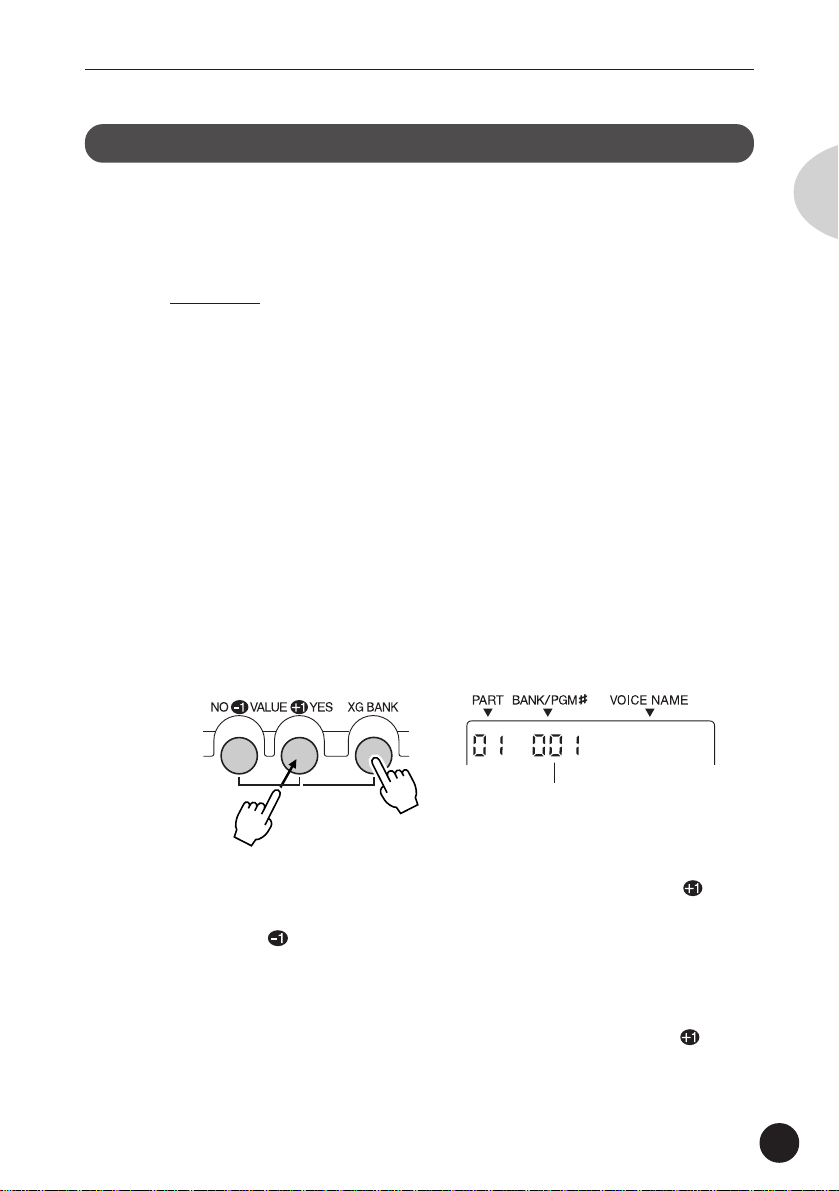
C Simultaneously hold down the XG BANK button and
press one of the VALUE buttons.
English
GrndPnoK
Bank number. (This changes to the
Voice number as soon as the XG
BANK button is released.)
Holding down the XG BANK button and pressing the VALUE /YES
button steps up through Bank numbers while doing the same with
the VALUE
Notice that the Bank numbers jump to seemingly random values.
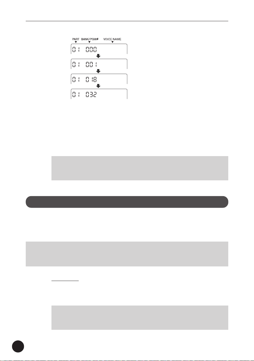
For example, if you’ve selected Voice number 005 “E.Piano1,”
holding down the XG BANK button and pressing the VALUE
button will step through the following Banks:
/NO button steps down through the numbers.
/YES
27
Page 28
Playing the MU15
E.Piano1
El.Pno1K
MelloEP1
Chor.EP1
…and so on.
In this way, the MU15 skips over Banks that have the same Voices
as the basic Bank (Bank 000), and lets you automatically jump to
Banks that have unique Voices for the selected Voice number. In the
above example, Banks 002 - 017 all have the same Voice for number
005: “E.Piano1.” Bank 018 has a unique Voice, followed by another
unique Voice at Bank 032, and so on.
NOTE
• When the SFX kit (XG Bank #126) or Drum kit (XG Bank #127) is
selected , the Voice number is automatically set to 001.
Playing Drum Voices
The MU15 also features a wide selection of dynamic, realistic drum and
percussion sounds. These sounds are grouped together in Drum Voices and
each note on the keyboard plays a different drum or percussion sound.
NOTE
• For details on which drum sounds are assigned to which notes of the keyboard,
refer to the Drum Map charts on pages 80 - 83.
28
Operation
Z Select Part 10.
Do this in the normal way, by using the PART buttons.
NOTE
• Part 10 is assigned to a Drum Voice by default. However, any Part can
be set to a Drum Voice by selecting Bank 126 or 127 for the Part.
Page 29
Playing the MU15
X Select the desired Drum Voice.
Do this in the normal way, by using the VALUE buttons.
C Play the drum sounds.
Play the sounds from the MU15’s keyboard or from a connected
MIDI keyboard.
Since the various drum/percussion sounds are spread out over
several octaves, in order to play them from the MU15, you’ll need to
change the octave setting (see next section).
Changing the Octave Setting
Although the MU15’s built-in keyboard has a two-octave range, you can
actually play it over a range of ten octaves.
Operation
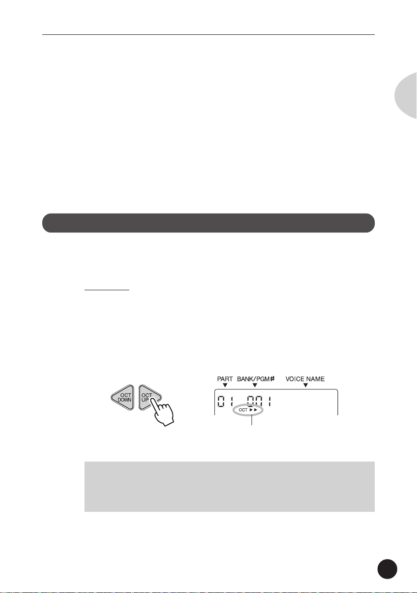
Use the OCT DOWN / OCT UP buttons.
Pressing the OCT DOWN button lowers the pitch by one octave, and
pressing the OCT UP button raises it by one octave. The current
octave setting is shown in the display. (No indication appears when
the octave setting is normal.)
English
GrandPno
Current octave setting. (In this example,
the pitch is two octaves above normal.)
NOTE
• For Normal Voices (such as Piano or Strings), this changes the pitch.
For Drum Voices, this changes the drum/percussion sounds playable
from the keyboard.
You can instantly restore the normal octave setting by pressing both
OCT DOWN / OCT UP buttons simultaneously.
29
Page 30
Playing the MU15
Editing a Part
The editing features of the MU15 provide various controls for changing the
Parts and setting other important operating functions. Among other things,
these let you set the Volume or Pan setting of each Part independently, change
the Velocity of the built-in keyboard, and save your edits to a connected
computer, sequencer or data storage device.
NOTE
• The Velocity and Local Control settings cannot be saved.
Editing on the MU15 is basically divided into three types of controls: Part,
Effect, and Utility. In this section, you’ll learn how to change the Note Shift
setting and the Volume setting (both Part controls). However, the instructions
given here are fundamentally the same for all editing operations. (See the
Reference section of this manual for information about the specific editing
functions.)
Changing the Note Shift and Volume Settings
The Note Shift parameter lets you change the key (pitch) of the
selected Part. This only affects the Normal Voices, and does not
change the pitch of the Drum Voices.
30
The Volume parameter allows you to change the level of each Part’s
Voice, letting you set a custom balance or mix of all the Parts.
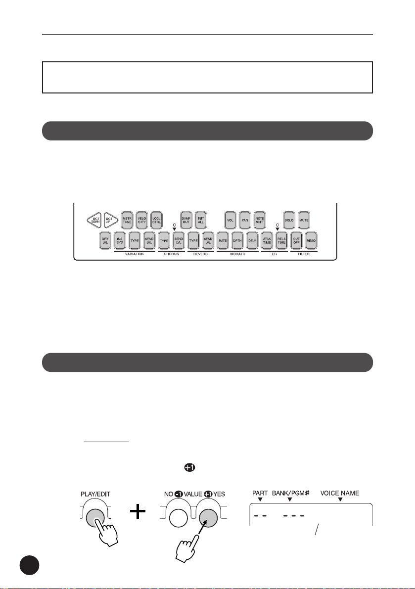
Operation
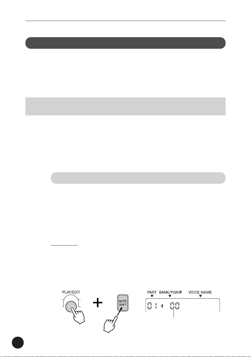
Z Select the desired parameter.
For Note Shift, simultaneously hold down the PLAY/EDIT button and
press the NOTE SHFT button. Doing this enters the Edit mode and
calls up the Note Shift parameter.
NoteShft
Current Note Shift value
Page 31

Playing the MU15
To select Volume, hold down PLAY/EDIT and press the VOL button.
X Change the value.
Use the VALUE buttons. For Note Shift,
the value changes in semitone steps up or
down, depending on which VALUE button
you press. For Volume, the value can be
changed over a range of 0 (minimum) to
127 (maximum).
Play the MU15 keyboard (or the connected MIDI keyboard) and hear
the change in the sound of the Part.
You can continue to change the selected setting with the VALUE
buttons and play the keyboard to hear the results of the changes. If
you wish, you can also easily change the setting for different Parts
by using the PART buttons to select the desired Part. To switch
between the desired parameters, repeat step #1 above.
English
C To return to the Play mode, press the PLAY/EDIT button
again.
Soloing and Muting Parts
The MU15 has convenient Solo and Mute functions for selectively soloing or
muting any of the sixteen Parts. These functions are especially useful when
playing back song data from a connected computer or sequencer, since they
let you isolate specific Parts in the mix and hear how they sound by themselves or how the rest of the song sounds without them.
For instructions on using Solo and Mute, see pages 48 and 49.
31
Page 32

Playing the MU15
Using the Effects
The compact MU15 is packed with an enormous amount of sonic power and
flexibility. In addition to the huge amount of instrument Voices, the MU15
features a built-in multi-effect processor with three independent digital effects:
Reverb, Chorus, and Variation.
In this section, you’ll learn how to apply the effects, change the effect type,
and set how much effect is applied for each Part. (See the Reference section
of this manual for information about specific effect parameters.)
Using Reverb and Chorus
Judicious use of Reverb creates a sense of space and enhances the
realism of the Voices. The Reverb Type that you select is applied to
all Parts; however, the amount of Reverb for each Part can be
adjusted. This lets you add special textures to the mix of a song,
such as “drenching” one Part in Reverb while another Part is kept
“dry.”
The Chorus effect section features a variety of pitch modulation
effects. These let you subtly enhance or “fatten” the sound, or
completely transform the sound in wild and unique ways. As with
Reverb, only one Chorus Type can be used for all Parts; however, the
amount of Chorus for each Part can be adjusted.
32
Since the methods of using Reverb and Chorus are identical, both
are covered here together.
Operation
Z Select the desired Part.
Do this in the normal way, by using the PART buttons.
X Set the Send Level controls to appropriate values.
Before you actually change the Reverb or Chorus settings, you
should set the Send Level controls, in order to properly hear the
effect and the changes you make.
Page 33

Playing the MU15
To do this, simultaneously hold down the PLAY/EDIT button and
press the REVERB SEND LVL button (for Reverb), or the CHORUS
SEND LVL button (for Chorus), and then set the value to “60” or
higher, by using the VALUE buttons.
RevSend
C Select the Reverb Type (or Chorus Type) parameter.
Simultaneously hold down the PLAY/EDIT button and press the
REVERB TYPE button (for Reverb), or the CHORUS TYPE button (for
Chorus).
Hall1
V Select the desired Reverb (or Chorus) Type.
Use the VALUE buttons. For a list of the available Reverb Types, see
page 57. For a list of the available Chorus Types, see page 58.
English
B Set the Send Level control to the desired value.
Once you’ve selected an Reverb or Chorus Type to your satisfaction,
you can re-adjust the effect level for the selected Part (and other
Parts, too). To do this, repeat steps #1 and #2 above.
Using the Variation Effects
The Variation effect section provides a wealth of additional effects,
with which you can enhance or radically change the sound of the
Voices.
Variation can be applied to all Parts (just as with Reverb and Chorus),
or to a single selected Part. (For more information on the Variation
effect, see page 59.)
33
Page 34

Playing the MU15
Operation
Z Select the desired Part.
Do this in the normal way, by using the PART buttons.
X Set Variation Connection to “SYS” (System).
Setting the Variation Connection parameter to “SYS” allows you to
use the Variation effect for all Parts. (For instructions on using the
“INS” or Insertion setting, see the boxed section on page 35.)
To do this, simultaneously hold down the PLAY/EDIT button and
press the INS SYS button, and then set the parameter to “SYS,” by
pressing the VALUE
/YES button.
SYS
C Set the Send Level controls to appropriate values.
Before you actually change the Variation settings, you should set the
Send Level controls, in order to properly hear the effect and the
changes you make.
34
To do this, simultaneously hold down the PLAY/EDIT button and
press the VARIATION SEND LVL button, and then set the value to
“60” or higher, by using the VALUE buttons.
VarSend
V Select the Variation Type parameter.
Simultaneously hold down the PLAY/EDIT button and press the
VARIATION TYPE button.
DelayLCR
Page 35

Playing the MU15
B Select the desired Variation Type.
Use the VALUE buttons. For a list of the available Variation Types,
see page 60.
N Set the Send Level control to the desired value.
Once you’ve selected a Variation Type to your satisfaction, you can
re-adjust the effect level for the selected Part (and other Parts, too).
To do this, repeat steps #1 and #3 above.
M Set the Dry Level control to the desired value.
This parameter gives you additional fine control over the Variation
effect balance. Setting this to a low value turns down the level of
the “dry” sound and emphasizes the Variation effect sound.
To do this, simultaneously hold down the PLAY/EDIT button and
press the DRY LVL button, and then set the value by using the
VALUE buttons.
DryLevel
English
Using the “INS” (Insertion) Setting
The “INS” (Insertion) setting lets you dedicate the Variation
effect to a single selected Part.
NOTE
• For the “INS” setting, the Send Level parameter can only be
turned on or off for the selected Part, and the Dry Level
parameter is unavailable.
1) Select the desired Part.
2) Set Variation Connection to “INS.” Simultaneously hold
down the PLAY/EDIT button and press the INS SYS button,
and then press the VALUE
3) Set the Send Level for the Part to “on.” Simultaneously
hold down the PLAY/EDIT button and press the VARIATION
SEND LVL button, and then press the VALUE
4) Select the desired Variation Type in the same way as
described in steps #4 and #5 in the main instructions above.
/NO button.
/YES button.
35
Page 36

Using the MU15 with a Computer/Sequencer
Using the MU15
with a Computer/Sequencer
By connecting the MU15 to a computer or sequencer, you have a powerful
music system for playing back songs and even creating your own songs, using
the Voices of the MU15.
First, you’ll have to make sure that the MU15 is properly connected to the
computer or sequencer, and that your music software is ready to run. (Refer to
page 37 for connection examples and instructions.) If you are using the TO
HOST terminal or if both MIDI terminals are properly connected, you should be
able to play songs from your software and enter notes to the software from
the MU15.
Using the MU15 with a MIDI Data Storage Device
You can also use the MU15 with a MIDI data storage device, such as
the Yamaha MDF3 MIDI Data Filer. This lets you save or back up
changes you’ve made in the settings of the Edit mode. Then, when
you want to recall those settings, you can transfer the appropriate
data from the storage device.
The MDF3 also allows you to play compatible song data on the
MU15 directly from the MDF3 itself, without the need of a sequencer.
Make sure that the MU15 is properly connected to the data storage
device (via MIDI). (Refer to page 66 for the connection example.)
Use the Dump Out function (page 65) to send data to the device.
Also refer to the owner’s manual of your data storage device for
specific operating instructions in receiving or sending data.
Setting Up
The MU15 features a built-in host computer interface, allowing you to directly
connect it to your computer — eliminating the need for installing a special
MIDI interface to your computer. This also makes it easier to use the MU15
36
Page 37

Using the MU15 with a Computer/Sequencer
with a laptop computer, giving you an exceptionally portable yet powerful
computer music system. The MU15 can be used with the following computers: Apple Macintosh and compatibles, or IBM PC/AT and compatibles.
If your computer already has a MIDI interface, you can connect the MU15 to it
by using MIDI cables instead.
Depending on the computer or interface used, you should set the HOST
SELECT switch to the appropriate setting: MIDI, PC-1, PC-2, or Mac. For
information on proper cables, see the section “MIDI/Computer Connecting
Cables” on page 41.
NOTE
• The PC-1 setting is designed only for use with computers in the Japanese domestic
market.
Operation
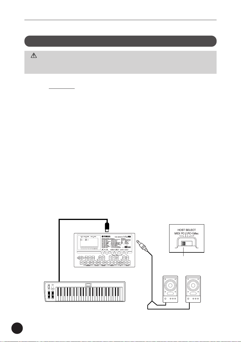
Z Set the HOST SELECT switch (on the rear panel) to the
appropriate setting.
English
For connecting to a MIDI interface: MIDI
For IBM PC/AT and compatibles: PC-2
For Apple Macintosh and compatibles: Mac
X Connect the equipment as shown in the illustrations
below.
If you are connecting directly to the TO HOST terminal, make sure to
use the following standard cable types:
For IBM PC/AT and compatibles: D-SUB 9-pin to mini
DIN 8-pin (page 41)
For Apple Macintosh and compatibles: 8-pin Macintosh
peripheral cable (page
41)
37
Page 38

Using the MU15 with a Computer/Sequencer
C Turn on the power of the computer first, and then the
MU15.
V Start up your music software, and (if necessary) set the
appropriate options on the software for operation with
the MU15. (See note on page 39.)
• Connecting via the TO HOST terminal
Connecting directly to an IBM PC/AT
compatible computer
MIDI keyboard controller
(Used as both tone generator
MU15
and MIDI interface.)
GrandPno
MIDI
OUT
MIDI
RS-232C
IBM-PC/AT or
(DB-9)
compatible computer
IN
TO HOST
Connecting directly to a Macintosh computer
TO HOST
RS422
Macintosh computer
PC-2
Mac
38
Page 39

Using the MU15 with a Computer/Sequencer
• Connecting via a MIDI interface
Connecting to a Macintosh computer
(with MIDI interface)
MIDI
MIDI interface
IN
MIDI
OUT
Macintosh computer
English
MIDI
MIDI keyboard controller
GrandPno
NOTE
• For Windows 95/98 users: In order to use the TO HOST connection,
• If the MU15 is connected to a computer via the TO HOST terminal and
• For Macintosh computers: You should set the MIDI interface clock
• If you are using the MU15 to enter notes to the computer and wish to
Connecting to an IBM PC/AT compatible
computer (with MIDI interface)
MIDI
IN
MIDI
OUT
IBM-PC/AT or compatible
computer
MIDI
MIDI
OUT
IN
MU15
you’ll need to install special MIDI driver software (YAMAHA CBX Driver
for Windows 95). You can obtain this driver from your local Yamaha
dealer, or download it via the Internet at:
http://www.yamaha.co.jp/english/xg/utility/tools.html
the power of the computer is turned off, an “IlglData” (Illegal Data)
error message appears, and the MU15 may not be operable. If this
happens, turn on your computer again. If this still doesn’t resolve the
problem, turn all equipment off and then back on again.
setting on the music software to 1 MHz.
hear what you are playing, you should set the music software to
“echo” the MIDI IN data to the MIDI OUT (on the computer). This is
usually done with a “MIDI Thru” or “MIDI Echo” option on the music
software.
MIDI
39
Page 40

Using the MU15 with a Computer/Sequencer
Playing Song Data
Once you set up your computer or sequencer with the MU15, you’re ready to
play back song data using the Voices of the MU15. Although any GM-compatible song data can be played, the MU15 will sound best when used with XGcompatible song data.
By using Yamaha’s XGworks Music Sequencer software, you can create your
own XG song data. Since XGworks also features a special XG Editor, you can
conveniently and easily edit any of the “hidden” parameters of the MU15.
This gives you comprehensive control over the Voices and effects. (For more
information on the “hidden” parameters, see the “MIDI Data Format” section,
page 91.)
When you do any editing to the MU15 for your own songs, you should save
your settings (as System Exclusive data) to the computer with the Dump Out
function (page 65). It’s especially useful to record this data at the beginning of
a song, so that the MU15 will be set properly for the particular song. Make
sure to enter several measures of silence before the song starts to accommodate the System Exclusive data.
40
Page 41

Using the MU15 with a Computer/Sequencer
MIDI/Computer Connecting Cables
MIDI
Standard MIDI cable. Maximum length 15 meters.
44
DIN 5-PIN
Macintosh
Apple Macintosh Peripheral cable (M0197). Maximum length 2
meters.
MINI DIN
8-PIN
PC-2
8-pin MINI DIN to D-SUB 9-pin cable. Maximum length 1.8 meters.
DIN 5-PIN
2 (GND)2
55
2 (HSK i)1
MINI DIN
1 (HSK 0)2
8-PIN
5 (RxD-)3
4 GND4
3 (TxD-)5
8 (RxD+)6
7 (GP i)7
6 (TxD+)8
English
MINI DIN
8-PIN
4 5 (GND)
8
8 (CTS)1
D-SUB
7 (RST)2
9-PIN
2 (RxD)3
3 (TxD) 5
This concludes your basic tour of the important functions of the MU15. To
find out more about how to best use your MU15, look through the
Reference section that follows and try out some of the functions and
operations that interest you.
41
Page 42

Reference
Reference
The Reference section of this manual covers in detail
all of the functions of the MU15. Refer to it when you
need information about a specific function, feature, or
operation.
Function Tree
Play Mode Part Select
Voice Select
Bank Select
Octave Down/Up
Demo Song
Edit Mode Part Controls Volume
Pan
Note Shift
Solo
Mute
Filter
EG
Vibrato
Effect Controls Reverb
Chorus
Variation
Utility Controls Master Tune
Velocity
Local Control
Dump Out
Initialize All
42
Page 43

Play Mode
Play Mode
The Play mode is the default mode of the MU15 and is automatically set when
the power is turned on. The Play mode allows you to play the Voices, either
from the MU15’s keyboard or from a MIDI device. Depending on data received
via MIDI, the MU15 operates in one of two Sound Module modes: XG or
TG300B. (XG is the default.)
The Play mode also lets you select Voices, Banks, and Parts, and change the
octave setting of the keyboard. If the Edit mode is selected, you can return to
the Play mode by pressing the PLAY/EDIT button.
For general instructions and details on various Play mode operations, refer to
the Guided Tour section.
Sound Module Mode
The MU15 plays Voices in one of two Sound Module modes: XG or TG300B.
The Sound Module mode is one of the “hidden” parameters of the MU15 and
can be changed only by incoming MIDI data. Normally this data is recorded at
the start of commercially available sequenced songs. If the song data is XGcompatible, the XG mode will be selected, letting you take advantage of the
MU15’s full performance power. If the song data is GM-compatible but
intended for another manufacturer’s tone generator, the TG300B mode will be
selected, enabling optimum playback of the song data.
English
You can change this setting yourself by the use of MIDI System Exclusive
messages (page 91), either as part of sequenced song data, or received from a
device that allows you to send user-specified System Exclusive data.
NOTE
• The last selected Sound Module mode is automatically enabled when the power is
turned on. However, if both the batteries and AC adaptor are removed (or if the
PLAY/EDIT button is pressed), the XG mode is automatically enabled.
When the TG300B mode is selected, the following display appears:
*
*
43
Page 44

Edit Mode
The XG mode features 480 Normal Voices (including 42 SFX Voices) and 11
Drum Voices (including 2 SFX drum kits). The TG300B mode features 579
Normal Voices and 10 Drum Voices.
NOTE
• In the TG300B mode, the Voices can only be selected by MIDI; they cannot be
selected from the panel of the MU15.
Edit Mode
The Edit mode allows you to change various settings and parameters of the
MU15. These controls are divided into three basic types: Part (page 45), Effect
(page 56), and Utility (page 63).
The basic method of editing is fundamentally the same for all of the parameters. Many of the parameters can be set independently for each Part, and as
such allow you to select the Part to be edited.
NOTE
• Keep in mind that the settings you make may automatically change when playing
back song data on a connected sequencer. If you want to save your original
settings, use the Dump Out function (page 65) before playing the song.
44
Operation
Z Select the desired edit parameter.
To do this, simultaneously hold down the PLAY/EDIT button and
press the appropriate button.
X Select the desired Part (if necessary).
Use the PART buttons.
Page 45

Edit Mode
NOTE
• Selecting a Part does not apply to the Utility controls or Effect controls,
except for the Send Level parameters (pages 57, 59, 61) and Dry Level
(when Variation Connection is set to “SYS”; page 62).
Once you’ve selected a certain parameter, you can instantly return to
that parameter from the Play mode by simply pressing the PLAY/
EDIT button.
C Change the setting or value.
Use the VALUE buttons. You can rapidly increase or decrease the
value by holding down the appropriate button. For even faster
editing, simultaneously hold down one button, and then press (or
hold down) the other. For example, to rapidly decrease the value,
simultaneously hold down the
button.
/NO button and press the /YES
Part Controls
English
Volume ................ 46
Pan ................ 47
Note Shift ................ 47
Solo ................ 48
Mute ................ 49
Filter Cutoff ................ 50
Resonance ................ 51
EG Attack Time .......... 52, 53
Release Time .......... 52, 53
Vibrato Rate ................ 54
Depth ................ 54
Delay ................ 55
45
Page 46

Edit Mode
The Part controls allow you to change certain parameters for each
Part. These include Volume, Pan, Note Shift, Filter, EG (Envelope
Generator) and Vibrato. All of these parameters can be set independently for each Part, giving you enormous and flexible control over
the sound. Also included in the Part controls are the convenient Solo
and Mute functions. The Effect Send Level parameters (pages 57,
59, 61) can also be adjusted for each Part.
Volume
Volume setting
Selected
Volume
Part
Graphically shows
Volume position for
each Part.
Range: 0 - 127
Default: 100
This determines the Volume of the selected Part. The Volume
setting is graphically represented by bars in the display.
NOTE
• Keep in mind that when playing the MU15’s keyboard, the actual sound
level of a selected Part also depends on the Velocity parameter in the
Utility controls (page 64). If the Velocity setting is at or near the
minimum, the Part may be very low in level, no matter what the
Volume setting made here.
46
Page 47

Edit Mode
Pan
Pan setting
Selected
Pan
Part
Graphically shows
Pan position for
each Part.
Range: Rnd, L 63 - C 00 - R 63
Default: C 00
This determines the stereo position of the selected Part. The Pan
position is graphically represented by bars in the display. The “Rnd”
(Random) setting randomly assigns the Voice to a pan position. This
is useful when you want to have different Voices sound from
different random positions of the stereo image.
A double bar in the middle represents the center position (C 00),
while right pan positions are indicated by bars stretching up from the
middle, and left pan positions are indicated by bars stretching down.
Note Shift
English
Note Shift
setting
Selected
NoteShft
Part
Shows Note Shift
setting for each
Part.
Range: -24 - +24 semitones
Default: 0
This determines the key transposition of the selected Part, over a
total range of four octaves in semitone steps. A Note Shift setting of
“0” results in normal pitch. This parameter has no effect on the
individual drum/percussion sounds of the Drum Voices.
47
Page 48

Solo setting
Edit Mode
Solo
Selected
Solo
Part
While a song is playing back on your computer or sequencer, you can
selectively solo any of the 16 Parts of the MU15. Solo lets you
isolate a single Part, to hear how that Part sounds by itself.
Along with Mute (page 49), Solo is an effective tool that helps you as
you edit the Parts, since it allows you to better hear how the
changes you make affect specific Voices as well as the overall
sound.
Operation
Shows Solo setting
for each Part.
Z Simultaneously hold down the PLAY/EDIT button and
press the SOLO button.
Solo
X Select the Part to be soloed.
Use the PART buttons.
48
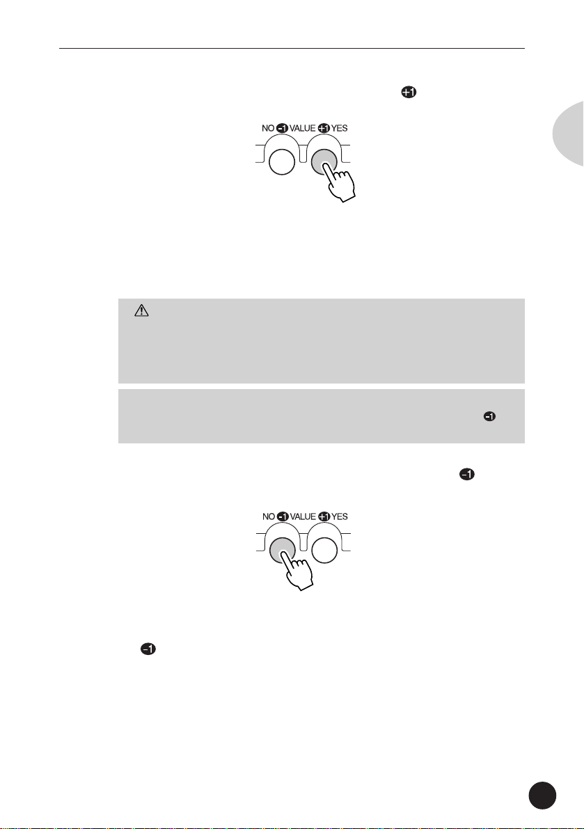
C To solo the selected Part, press the VALUE /YES
button. To hear all Parts normally, press the VALUE
NO button.
The display indicates the Solo status of the Part. For example, when
Part 2 is being soloed (Solo is on), the following display is shown:
Solo
Part 2 is soloed.
/
Page 49

Edit Mode
Mute
Mute setting
Selected
Mute
Part
While a song is playing back on your computer or sequencer, you can
selectively mute any of the 16 Parts of the MU15. Mute lets you
silence one Part to hear how all of the other Parts sound without it.
Along with Solo (page 48), Mute is a convenient tool, since it allows
you to hear how the presence or absence of specific Parts affects
the overall sound.
Operation
Z Simultaneously hold down the PLAY/EDIT button and
press the MUTE button.
Mute
Shows Mute
setting for each
Part.
English
X Select the Part to be muted.
Use the PART buttons.
C To mute the selected Part, press the VALUE /YES
button. To un-mute it, press the VALUE
The display indicates the Mute status of the Part. For example,
when Part 2 is being muted (Mute is on), the following display is
shown:
/NO button.
Mute
Part 2 is muted.
49
Page 50

Edit Mode
Filter Parameters — Cutoff Frequency
and Resonance
The MU15 features digital filters for each Part that allow you to change the
timbre or tone of the Voices. The filters are affected (together with the level)
by the EG (Envelope Generator) parameters, which allow you to change the
timbre over time as well. (Page 52.)
Cutoff Frequency
Cutoff Frequency
setting
Selected
Cutoff
Part
Range: -64 - +63
Default: 0
This determines the cutoff frequency of the filter. The filter effectively takes out frequencies higher than the cutoff point and
“passes” the lower frequencies. Lower cutoff values create a
deeper, more rounded tone, while higher values create a brighter
tone.
Shows Cutoff
Frequency setting
for each Part.
50
Level
These frequencies
are “passed” or let
through.
These frequencies are
“cut” or filtered out.
Frequency
Cutoff Frequency
setting
Page 51

Edit Mode
Resonance
Resonance
setting
Selected
Reso
Part
Range: -64 - +63
Default: 0
This determines the amount of filter resonance or emphasis of the
Cutoff Frequency parameter above. Higher values make the filter
effect more pronounced and stronger, creating a resonant peak
around the cutoff frequency.
Level
Resonance
Frequency
Cutoff Frequency setting
Shows Resonance
setting for each
Part.
English
51
Page 52

Edit Mode
EG (Envelope Generator) Parameters —
Attack Time and Release Time
The EG parameters allow you to shape the sound of a Part’s Voice — or, in
other words, set how the level and timbre of the Voice changes over time.
The relationship of the two EG parameters — Attack Time and Release Time —
are shown in the illustrations below. These parameters affect both the volume
of the Voice and its timbre (with the Filter parameters; page 50).
1) Short Attack and Release Times
Level
Attack Time Release Time
Max.
52
Min.
Key is pressed
Key is released
Time
2) Long Attack and Release Times
Level
Attack Time Release Time
Max.
Min.
Key is pressed
Key is released
Time
Even though the key is held for the same length of time in both
examples, the sound of the second example takes a much longer
time to reach full volume and sustains longer after the key is released.
Page 53

Edit Mode
Attack Time
Attack Time
setting
Selected
AtckTime
Part
Shows Attack Time
setting for each
Part.
Range: -64 - +63
Default: 0
This determines the Attack Time of the EG, or how long it takes for
the sound to reach full volume when a note is played. Higher
positive values result in a longer, slower attack. For the Filter, this
determines how long it takes for the sound to be affected by the
Filter values.
Release Time
Release Time
setting
Selected
RelsTime
Part
Shows Release
Time setting for
each Part.
English
Range: -64 - +63
Default: 0
This determines the Release Time of the EG, or how long the sound
sustains after a note is released. Higher positive values result in a
longer, slower sustain. For the Filter, this determines how long the
Filter effect continues after a note is released.
NOTE
• Short percussive Voices (such as Marimba) whose sound decays very
quickly may not be affected by the Release Time parameter, depending
on how long the key is held. For example, if the key is held until the
sound completely dies out, there will be no sound to slowly sustain, no
matter what the Release Time setting is.
53
Page 54

Edit Mode
Vibrato Parameters — Rate, Depth, and Delay
Vibrato produces a quavering, vibrating sound in the Part’s Voice, by regularly
modulating the pitch. You can control the speed and depth of the Vibrato, as
well as the time it takes before the Vibrato effect is applied.
Vibrato Rate
Vibrato Rate
setting
Selected
VibRate
Part
Range: -64 - +63
Default: 0
This determines the speed of the Vibrato effect. Negative values
produce a very slow Vibrato, while higher values result in a faster
Vibrato sound.
Shows Vibrato Rate
setting for each
Part.
54
Vibrato Depth
Vibrato Depth
setting
Selected
VibDepth
Part
Range: -64 - +63
Default: 0
This determines the depth of the Vibrato effect. Higher values result
in a stronger, more pronounced Vibrato sound.
Shows Vibrato
Depth setting for
each Part.
Page 55

Edit Mode
Vibrato Delay
Vibrato Delay
setting
Selected
VibDelay
Part
Range: -64 - +63
Default: 0
This determines the delay in the start of the Vibrato effect. Delay is
effective especially for producing a natural sound on stringed
instrument Voices. For example, violin players often use delayed
Vibrato, especially while playing long notes. The Delay parameter is
useful in recreating this effect, producing a richer, more lifelike
sound. Higher values result in a longer Delay time.
Shows Vibrato
Delay setting for
each Part.
English
55
Page 56

Edit Mode
Effect Controls
Reverb Type ................ 57
Send Level ................ 57
Chorus Type ................ 58
Send Level ................ 59
Variation Connection ................ 60
Type ................ 60
Send Level ................ 61
Dry Level ................ 62
The MU15 features a built-in multi-effect processor with three
independent digital effects: Reverb, Chorus, and Variation.
Reverb Parameters
Reverb recreates the sounds of various performance environments by adding
an ambient wash of delays or reflections. Several different types of Reverb
effects are available to simulate the ambience of different sized rooms.
For general information on using the Reverb effect, see page 32.
56
Page 57

Edit Mode
Reverb Type
The current Type setting
RevType
appears in the LCD as
soon as the TYPE
button is released.
Hall1
Reverb Type
setting
Settings: NoEffect, Hall1 - 2, Room1 - 3, Stage1 - 2, Plate,
W-Room (White Room), Tunnel, Basement
Default: Hall1
This determines the Type of Reverb effect, or the performance
environment that is simulated. When “NoEffect” is selected, the
Reverb effect is turned off.
Reverb Send Level
Reverb Send
Level setting
Selected
RevSend
Part
Shows Reverb
Send Level setting
for each Part.
English
Range: 0 - 127
Default: 40
This determines the level of the selected Part’s Voice that is sent to
the Reverb effect. Each Part can be set independently for different
amounts of Reverb on each Voice. A value of “0” results in a
completely “dry” Voice sound.
NOTE
• Keep in mind that Reverb Type (above) must be set to something other
than “NoEffect” for this parameter to work as intended.
57
Page 58

Edit Mode
Chorus Parameters
Chorus uses pitch modulation to create a variety of rich, spacious-sounding
effects, including Chorus, Celeste, and Flanger.
For general information on using the Chorus effect, see page 32.
Chorus Type
The current Type setting
ChoType
Chorus1
appears in the LCD as
soon as the TYPE
button is released.
Chorus Type
setting
58
Settings: NoEffect, Chorus1 - 4, Celeste1 - 4, Flanger1 - 3
Default: Chorus1
This determines the Type of Chorus effect. When “NoEffect” is
selected, the Chorus effect is turned off.
Chorus and Celeste are used to subtly enhance the sound, and
generally make it richer, fatter, and warmer. Flanger uses modulation
to create an animated, swirling motion effect, and produces a
characteristic metallic sound.
Page 59

Edit Mode
Chorus Send Level
Chorus Send
Level setting
Selected
ChoSend
Part
Range: 0 - 127
Default: 0
This determines the level of the selected Part’s Voice that is sent to
the Chorus effect. Each Part can be set independently for different
amounts of Chorus on each Voice. A value of “0” results in a
completely “dry” Voice sound (no Chorus effect).
NOTE
• Keep in mind that Chorus Type (page 58) must be set to something
other than “NoEffect” for this parameter to work as intended.
Shows Chorus
Send Level setting
for each Part.
English
Variation Parameters
The Variation effects provide a wealth of additional tools for processing the
Voices of the MU15. It features most of the same effects found in the Reverb
and Chorus effects. This is not mere redundancy; it allows you to use two
types of Reverb or Chorus simultaneously on different Voices. For example,
you may want to have a Chorus effect on Voice and apply Flanger to another.
Variation also gives you many special effects not found in the other sections,
such as Delay, Gate Reverb, Rotary Speaker, and Wah.
Variation effects can be applied either to a single selected Part or to all Parts,
depending on the Variation Connection setting (page 60): Insertion or System.
For general information on using the Variation effect, see page 33.
59
Page 60

Edit Mode
Variation Connection
The current Variation
VarCnct
INS
Settings: INS (Insertion), SYS (System)
Default: INS
This determines how the Variation effect is connected in the effect
chain of the MU15. When set to “SYS” (System), Variation is
applied to all Parts, according to the amount of Variation Send Level
(page 61) set for each Part. When set to “INS” (Insertion), Variation
is applied to only the selected Part, also set in the Variation Send
Level parameter.
Connection setting
appears in the LCD as
soon as the INS/SYS
button is released.
Variation Connection
setting
60
Variation Type
The Type setting
VarType
DelayLCR
Settings: NoEffect, Hall1 - 2, Room1 - 3, Stage1 - 2, Plate,
DelayLCR, DelayLR, Echo, CrsDelay (Cross Delay),
E-Ref1 - 2 (Early Reflections), GateRev (Gate Reverb),
RvsGate (Reverse Gate), Karaoke1 - 3, Chorus1 - 4,
Celeste1 - 4, Flanger1 - 3, Symphnic (Symphonic),
appears in the LCD as
soon as the TYPE
button is released.
Variation Type
setting
Page 61

Edit Mode
RotarySp (Rotary Speaker), Tremolo, AutoPan,
Phaser1 - 2, Dist (Distortion), OverDrv (Overdrive),
AmpSim (Amp Simulator), 3BandEQ, 2BandEQ, AutoWah,
PitchCng (Pitch Change), Thru
Default: DelayLCR
This determines the Type of the Variation effect.
About “NoEffect” and “Thru”
When Variation Connection is set to “INS” and “NoEffect” is
selected, the sound for the Part is turned off (there is no “dry”
sound). When “Thru” is selected, you can hear the dry, unprocessed sound.
NOTE
• The 3BandEQ and 2BandEQ Types have little effect on the sound
unless the “hidden” parameters are changed via MIDI. (Page 91.)
Variation Send Level
English
Variation Send
Level setting
Selected
VarSend
Part
Shows Variation
Send Level setting
for each Part.
Settings: off, on (when Variation Connection is set to “INS”)
0 - 127 (when Variation Connection is set to “SYS”)
Default: off (for “INS”)
0 (for “SYS”)
When the Variation Connection parameter (page 60) is set to “INS,”
this determines whether the Variation effect is applied to the selected Part or not. Also, since the Variation effect cannot be used
simultaneously on several Parts (for “INS”), only the last Part for
which this parameter has been set to “on” will have the Variation
effect. A setting of “off” results in no Variation effect being applied.
61
Page 62

Edit Mode
When the Variation Connection parameter (page 60) is set to “SYS,”
this determines the level of the selected Part’s Voice that is sent to
the Variation effect. In this case, each Part can be set independently
for different amounts of Variation on each Voice. A value of “0”
results in a completely “dry” Voice sound (no Variation effect).
NOTE
• Keep in mind that Variation Type (page 60) must be set to something
other than “NoEffect” or “Thru” for this parameter to work as
intended.
• If the Variation Type is set to “NoEffect” and Variation Connection is set
to “INS,” there will be no sound for the Part. To remedy this, set the
Type to “Thru” or to one of the other effect Types. (Page 60.)
Dry Level
Dry Level
setting
Selected
DryLevel
Part
Shows Dry Level
setting for each
Part.
62
Range: 0 - 127
Default: 127
This determines the level or volume of the selected Part’s “dry”
sound — the sound of the Voice without the effects. Dry Level gives
you additional fine control over the effect balance. Setting this to a
low value turns down the level of the “dry” sound and emphasizes
the effect sound.
NOTE
• When Variation Connection is set to “INS,” the Dry Level parameter is
automatically set to “off” and cannot be changed.
Page 63

Edit Mode
Utility Controls
Master Tune ................ 63
Velocity ................ 64
Local Control ................ 64
Dump Out ................ 65
Initialize All ................ 68
Master Tune
Tuning value
MstrTune
English
Range: +/- 999 (in 0.1 cent steps)
Default: 0
This determines the overall fine tuning of the MU15’s Voices. It
does not affect the pitch of the individual drum/percussion sounds of
the Drum Voices. Master Tune is especially useful for adjusting the
pitch of the MU15 when playing with other instruments. (The actual
pitch of each Part depends also on the Note Shift parameter on page
47.)
63
Page 64

Edit Mode
Velocity
Velocity setting
Velocity
Range: 1 - 127
Default: 88
This determines the note on velocity of the MU15’s built-in keyboard.
All notes that you play from the panel keyboard will be at this fixed
velocity, and sound at the same level. This velocity is also transmitted to connected devices via the MIDI OUT or TO HOST terminals.
However, it does not affect the incoming velocity of notes played
from a connected sequencer or external keyboard.
NOTE
• Settings of 20 or less may result in little or no sound. For normal
applications, make sure this is set to around 88 (default).
• Keep in mind that when playing the MU15’s keyboard, the actual sound
level of a selected Part also depends on the Volume parameter in the
Part controls (page 46). If the Volume setting is at or near the minimum, the Part may be very low in level, no matter what the Velocity
setting made here.
64
Local Control
Local Control
setting
LoclCtrl
Page 65

Edit Mode
Range: off, on
Default: on
This determines whether or not the internal tone generator responds
to the notes you play on the MU15’s keyboard. Normally, this should
be on. Setting this to “off” effectively disconnects the panel
keyboard from the internal tone generator. Even when this is set to
“off,” notes played on the keyboard are still transmitted via the TO
HOST or MIDI OUT terminals.
HINT
• A common application of Local Control is when using the MU15 to
input notes into a sequencer. If the sequencer is also set up to play
back data using the Voices of the MU15, when you play the MU15, it
will be sounding its own Voices twice — once from the keyboard, and
after a very brief delay, again from the MIDI data coming from the
sequencer. This not only decreases the available polyphony of the
MU15 by half, it also creates an undesirable flanging sound. To remedy
this, set Local Control to “off.”
• Another useful application of the “off” setting of this parameter is
when you’ve connected the MU15 to another tone generator and want
to play only that tone generator and leave the MU15 Voices silent.
English
Dump Out
DumpOut
This function allows you to save the current parameter settings of
the MU15 to a MIDI sequencer, computer or a MIDI data recorder
(such as the Yamaha MDF3 MIDI Data Filer).
65
Page 66

Edit Mode
• Saving and Restoring Data via MIDI
GrandPno
MU15
MIDI OUT
MIDI IN MIDI OUT
Bulk Dump data can be sent and
received using the MIDI IN and
MIDI OUT connections.
MIDI IN
MIDI Data
Recorder
• Saving and Restoring Data via TO HOST
COMPUTER/
MIDI Data Recorder
GrandPno
MU15
TO HOST
Bulk Dump data can be sent and
received using the TO HOST
connection.
SERIAL PORT
Operation
Z Make sure that the MU15 is properly connected to the
device and that the HOST SELECT switch is properly
set.
66
When using the MIDI terminals, connect the MIDI OUT of the MU15
to the MIDI IN of the data recorder. (See the “Saving and Restoring
Data via MIDI” illustration above.) Also, set the HOST SELECT
switch to MIDI.
When using the TO HOST terminal, make sure that the HOST
SELECT switch is set corresponding to the device to be used. (See
the “Saving and Restoring Data via TO HOST” illustration above.)
For more information on host computer connections, see page 37.
X Set the connected device to receive MIDI System Exclu-
sive data.
Refer to the owner’s manual of the particular device or software for
instructions on receiving System Exclusive data.
Page 67

Edit Mode
C Simultaneously hold down the PLAY/EDIT button and
press the DUMP OUT button.
DumpOut
V At the “DumpOut” message, press the VALUE /YES
button.
Sure?
B At the “Sure?” prompt, press the VALUE /YES but-
ton.
A “Transmit” message appears in the display during the operation.
When the operation is completed, a “Complete” message briefly
appears. To cancel the operation at the “Sure?” prompt, press the
VALUE
/NO button.
To reload the data from the data recorder back to the
MU15
Make sure that the devices are properly connected (see the illustrations on page 66), and execute the appropriate data transfer operation from the data recorder. (Refer to the owner’s manual of that
device or software for instructions.) The MU15 automatically
receives incoming bulk data.
English
NOTE
• This operation does not save settings of parameters which cannot be
controlled via MIDI (such as Velocity and Local Control).
67
Page 68

Edit Mode
Initialize All
InitAll
This operation allows you to restore the original factory settings of
the MU15.
CAUTION
• Using Initialize All will erase whatever settings you’ve made on the
MU15. If you have important settings you wish to keep, store them to
a MIDI data recorder with the Dump Out function. (See page 65.)
Operation
68
Z Simultaneously hold down the PLAY/EDIT button and
press the INIT ALL button.
InitAll
X At the “InitAll” message, press the VALUE
button.
/YES
Sure?
C At the “Sure?” prompt, press the VALUE /YES but-
ton.
An “Execute” message appears in the display during the operation.
Once started, the operation cannot be stopped. When the operation
is completed, a “Complete” message briefly appears.
Page 69

Appendix
Appendix
Troubleshooting
Even though the MU15 is exceptionally easy to use, it may occasionally not
function as you expect it to. If that happens, check the possible problems and
solutions below before assuming that the instrument is faulty.
English
Problem
No power.
No sound.
No sound when playing the
keyboard on the MU15.
Possible Cause and Solution
• If you are using an AC adaptor, check that
the adaptor properly plugged into both the
AC outlet and the MU15 (Page 18.)
• If you are using batteries, check that a
fresh set of batteries properly installed in
the battery compartment. (Page 19.)
• Check that the side panel volume control
is set to an appropriate level. (Pages 16,
21.)
• Check that other volume-related parameters are set to appropriate levels. (See
Velocity, page 64, and Volume, page 46.)
• Check the Mute and Solo settings.
(Pages 48, 49.) If a Part is being muted,
or an empty Part is being soloed, you may
not get any sound.
• Check that Local Control is set to on.
(Page 64.) Also check the points for “No
Sound” above.
69
Page 70

Troubleshooting
Problem Possible Cause and Solution
No sound when playing the
MU15 from a computer,
sequencer or external
keyboard.
No sound of a specific Part.
• Check all MIDI connections, making sure
that the MIDI OUT of the external device
is connected to the MIDI IN of the MU15,
and that the MIDI IN of the external
device is connected to the MIDI OUT of
the MU15. (Page 39.) Or, if you are using
the TO HOST terminal with a computer,
make sure that the terminal is properly
connected to the computer and that the
HOST SELECT switch is properly set for
your particular computer. (Page 37.)
• Check the settings of the connected MIDI
device. If Expression and Master Volume
are set to low values, the MU15 may put
out little or no sound.
• Check the Mute setting. (Page 49.) If a
Part is being muted, it will not sound.
• Check the Variation effect settings. If
Variation Connection (page 60) is set to
“INS” and Variation Type is set to
“NoEffect,” the selected Part may not
sound. Also, if Variation Type is set to
“NoEffect” or “Thru” and Dry Level is set
near or at the minimum value, the
selected Part may not sound.
Notes are cut off or omitted.
When using a sequencer or
computer, an unusual “flanging” sound occurs and/or not
all notes seem to sound.
Even though Local Control is
set to “off,” the MU15
continues to sound when
playing the built-in keyboard.
70
• The maximum polyphony of the MU15
may be exceeded. The MU15 can play no
more than 32 notes at once.
• Check that Local Control is set to “off.”
(Page 64.) Also, check the settings on
your sequencer or computer (such as
“MIDI Thru” or “MIDI Echo”).
• This is normal, if you’ve routed the MU15
to a sequencer or computer and that
device’s “MIDI Thru” or “MIDI Echo”
option is turned on.
Page 71

Error Messages
Error Messages
Errors may occur from time to time, and when they do the MU15 will display a
message to indicate the type of problem so that you can rectify it and return to
normal operation.
“Battery”
The battery voltage is too low for proper operation. Replace the old batteries
with a set of new ones. (Page 19.)
“CheckSum” (Checksum Error)
The checksum of the received System Exclusive message is incorrect. Check
the checksum of the message and try transmitting again. (The checksum
which is calculated for the received data will be displayed.)
“IlglData” (Illegal Data)
A data error resulted during reception of MIDI messages. Try transmitting the
data again, or turn the MU15 off and back on again.
Or the MU15 is connected to a computer via the TO HOST terminal and the
power of the computer is turned off. Turn on your computer again. If this still
doesn’t resolve the problem, turn all equipment off and then back on again.
“BuffFull” (MIDI Buffer Full)
Too much MIDI data is being received by the MU15 at one time. Reduce the
amount of data being sent to the MU15.
English
“MIDIAdrs” (System Exclusive Address Error)
The data of the received System Exclusive message is incorrect. Check the
address of the message and try transmitting again.
“MIDIData” (System Exclusive Data Error)
An error has been detected in the MIDI System Exclusive data received by the
MU15. Check the data of the message (as to whether it requires an MSB or
LSB header) and try transmitting again.
“BulkSize” (System Exclusive Size Error)
The data of the received System Exclusive message is incorrect. Check the
size of the message and try transmitting again.
71
Page 72

Specifications
Specifications
Tone Generation Method
Advanced Wave Memory 2 (AWM2)
Polyphony
32-note (Dynamic Voice Allocation)
Multi-timbral Capacity
16-Part
Demo Song
1 (not editable, stored in ROM)
Display
Custom LCD (54.5 mm x 29.4 mm)
Controls
PART
UP; keypad (for playing Voices or accessing Edit functions); ON/STANDBY
switch; HOST SELECT switch; VOLUME control
, ; VALUE /NO, /YES; XG BANK, PLAY/EDIT; OCT DOWN,
Jacks and Terminals
MIDI OUT and MIDI IN terminals, TO HOST terminal (8-pin mini DIN), DC IN
jack, LINE OUT/PHONES jack
Host Computer Interface and Data Baud Rate
MIDI — 31,250 bps (bits per second)
Mac — 31,250 bps
PC-1 — 31,250 bps
PC-2 — 38,400 bps
Power Supply
YAMAHA PA-3B AC Power Adaptor (sold separately).
Six “AA” size, SUM-3, R-6 or equivalent batteries (sold separately).
Dimensions (W x D x H)
188 x 104 x 33 mm (7-3/8” x 4-1/8” x 1-5/16”)
Weight
350 g (12.3 oz.) (without batteries)
* Specifications and descriptions in this owner’s manual are for information purposes only.
Yamaha Corp. reserves the right to change or modify products or specifications at any time
without prior notice. Since specifications, equipment or options may not be the same in every
locale, please check with your Yamaha dealer.
72
Page 73

Index
Index
A
Attack Time ............................. 52, 53
B
Banks ...................................... 26, 27
Banks, selecting ............................ 27
batteries, replacing ........................ 19
batteries, using.............................. 19
C
Chorus ..................................... 32, 58
Chorus Send Level ........................ 59
Chorus Type .................................. 58
computer, connections............ 38, 39
computer, IBM ........................ 38, 39
computer, Macintosh .............. 38, 39
connections, audio ........................ 20
connections, computer ........... 38, 39
connections, MIDI ................... 20, 39
Cutoff ............................................ 50
English
G
GM (General MIDI) .................... 5, 12
H
headphones............................. 16, 20
“hidden” parameters ........ 40, 43, 91
I
Initialize All .................................... 68
INS (Insertion) ......................... 35, 60
L
Local Control ................................. 64
M
Master Tune .................................. 63
MIDI ...................... 12, 15, 20, 36, 91
MIDI Channel ................................ 91
MIDI data storage device ........ 36, 65
Mute.............................................. 49
D
Demo Song ................................... 22
Drum Voices .................................. 28
Dry Level ....................................... 62
Dump Out ..................................... 65
E
editing ..................................... 30, 44
Effect controls ............................... 56
EG (Envelope Generator)............... 52
F
Filter .............................................. 50
N
Note Shift ................................ 30, 47
O
octave setting................................ 29
P
Pan ................................................ 47
Part controls .................................. 45
Parts .................................. 25, 26, 30
Parts, muting ................................. 49
Parts, selecting.............................. 26
Parts, soloing................................. 48
Play mode ..................................... 43
power adaptor, using ..................... 18
73
Page 74

R
Release Time ........................... 52, 53
Resonance .................................... 51
Reverb ..................................... 32, 56
Reverb Send Level ........................ 57
Reverb Type .................................. 57
S
Solo ............................................... 48
Sound Module mode..................... 43
SYS (System) .......................... 34, 60
T
TG300B mode ............................... 43
U
Utility controls ............................... 63
V
Variation ................................... 33, 59
Variation Connection ............... 34, 60
Variation Send Level ................ 34, 61
Variation Type ................................ 60
Velocity .......................................... 64
Vibrato ........................................... 54
Vibrato Delay ................................. 55
Vibrato Depth ................................ 54
Vibrato Rate................................... 54
Voices ................................ 10, 24, 25
Voices, selecting ........................... 24
Volume .......................................... 46
Index
X
XG format .................................. 5, 12
XG mode ....................................... 43
74
Page 75

Sound List &
Sound List &
MIDI Data
MIDI Data
XG Normal Voice List.............................. 76
TG300B Normal Voice List ...................... 78
XG Drum Voice List (Drum Map) ............ 80
TG300B Drum Voice List (Drum Map) .... 82
Effect Type List ....................................... 84
Effect Parameter List .............................. 85
Effect Data Assign Table......................... 90
MIDI Data Format................................... 91
MIDI Implementation Chart ................. 108
75
Page 76

XG Normal Voice List
Bank Select MSB=000, LSB=Bank Number
Instrument
Instrument
Program#Bank
Group
Piano 1 0 GrandPno 1
Chromatic 9 0 Celesta 1
Percussion 10 0 Glocken 1
Voice Name
#
1 GrndPnoK 1
18 MelloGrP 1
40 PianoStr 2
41 Dream 2
2 0 BritePno 1
1 BritPnoK 1
3 0 El.Grand 2
1 ElGrPnoK 2
32 Det.CP80 2
40 LayerCP1 2
41 LayerCP2 2
4 0 HnkyTonk 2
1 HnkyTnkK 2
5 0 E.Piano1 2
1 El.Pno1K 1
18 MelloEP1 2
32 Chor.EP1 2
40 HardEl.P 2
45 VX El.P1 2
64 60sEl.P1 1
6 0 E.Piano2 2
1 El.Pno2K 1
32 Chor.EP2 2
33 DX Hard 2
34 DXLegend 2
40 DX Phase 2
41 DX+Analg 2
42 DXKotoEP 2
45 VX El.P2 2
7 0 Harpsi. 1
1 Harpsi.K 1
25 Harpsi.2 2
35 Harpsi.3 2
8 0 Clavi 2
1 Clavi K 1
27 ClaviWah 2
64 PulseClv 1
65 PierceCl 2
11 0 MusicBox 2
64 Orgel 2
12 0 Vibes 1
1 Vibes K 1
45 HardVibe 2
13 0 Marimba 1
1 MarimbaK 1
64 SineMrmb 2
97 Balimba 2
98 Log Drum 2
14 0 Xylophon 1
15 0 TubulBel 1
96 ChrchBel 2
97 Carillon 2
16 0 Dulcimer 1
35 Dulcimr2 2
96 Cimbalom 2
97 Santur 2
ment
Ele-
Program#Bank
Group
Organ 17 0 DrawOrgn 1
Guitar 25 0 NylonGtr 1
Voice Name
#
32 DetDrwOr 2
33 60sDrOr1 2
34 60sDrOr2 2
35 70sDrOr1 2
36 DrawOrg2 2
37 60sDrOr3 2
38 Even Bar 2
40 16+2"2/3 2
64 Organ Ba 1
65 70sDrOr2 2
66 CheezOrg 2
67 DrawOrg3 2
18 0 PercOrgn 1
24 70sPcOr1 2
32 DetPrcOr 2
33 Lite Org 2
37 PercOrg2 2
19 0 RockOrgn 2
64 RotaryOr 2
65 SloRotar 2
66 FstRotar 2
20 0 ChrchOrg 2
32 ChurOrg3 2
35 ChurOrg2 2
40 NotreDam 2
64 OrgFlute 2
65 TrmOrgFl 2
21 0 ReedOrgn 1
40 Puff Org 2
22 0 Acordion 2
32 AccordIt 2
23 0 Harmnica 1
32 Harmo. 2 2
24 0 TangoAcd 2
64 TngoAcd2 2
16 NylonGt2 1
25 NylonGt3 2
43 VelGtHrm 2
96 Ukulele 1
26 0 SteelGtr 1
16 SteelGt2 1
35 12StrGtr 2
40 Nyln&Stl 2
41 Stl&Body 2
96 Mandolin 2
27 0 Jazz Gtr 1
18 MelloGtr 1
32 Jazz Amp 2
28 0 CleanGtr 1
32 ChorusGt 2
29 0 Mute Gtr 1
40 FunkGtr1 2
41 MuteStlG 2
43 FunkGtr2 2
45 Jazz Man 2
30 0 Ovrdrive 1
43 Gt.Pinch 2
31 0 Dist.Gtr 1
40 FeedbkGt 2
41 FeedbkG2 2
32 0 GtrHarmo 1
65 GtFeedbk 1
66 GtrHrmo2 1
Instrument
Ele-
Group
ment
Bass 33 0 Aco.Bass 1
Strings 41 0 Violin 1
Bank
Program
#
#
40 JazzRthm 2
45 VXUprght 2
34 0 FngrBass 1
18 FingrDrk 2
27 FlangeBa 2
40 Ba&DstEG 2
43 FngrSlap 2
45 FngBass2 2
65 Mod.Bass 2
35 0 PickBass 1
28 MutePkBa 1
36 0 Fretless 1
32 Fretles2 2
33 Fretles3 2
34 Fretles4 2
96 SynFretl 2
97 SmthFrtl 2
37 0 SlapBas1 1
27 ResoSlap 1
32 PunchThm 2
38 0 SlapBas2 1
43 VeloSlap 2
39 0 SynBass1 1
18 SynBa1Dk 1
20 FastResB 1
24 AcidBass 1
35 Clv Bass 2
40 TechnoBa 2
64 Orbiter 2
65 Sqr.Bass 2
66 RubberBa 2
96 Hammer 2
40 0 SynBass2 2
6 MelloSBa 1
12 Seq Bass 2
18 ClkSynBa 2
19 SynBa2Dk 1
32 SmthSynB 2
40 ModulrBa 2
41 DX Bass 2
64 X WireBa 2
8 Slow Vln 1
42 0 Viola 1
43 0 Cello 1
44 0 Contrabs 1
45 0 Trem.Str 1
8 SlwTrStr 1
40 Susp.Str 2
46 0 Pizz.Str 1
47 0 Harp 1
40 YangChin 2
48 0 Timpani 1
Voice Name
Instrument
Ele-
Group
ment
Ensemble 49 0 Strings1 1
Brass 57 0 Trumpet 1
Bank
Program
#
#
3 S.Strngs 2
8 Slow Str 1
24 Arco Str 2
35 60sStrng 2
40 Orchestr 2
41 Orchstr2 2
42 TremOrch 2
45 VeloStr 2
50 0 Strings2 1
3 S.SlwStr 2
8 LegatoSt 2
40 Warm Str 2
41 Kingdom 2
64 70s Str 1
65 Strings3 1
51 0 Syn Str1 2
27 Reso Str 2
64 Syn Str4 2
65 Syn Str5 2
52 0 Syn Str2 2
53 0 ChoirAah 1
3 S.Choir 2
16 Ch.Aahs2 2
32 MelChoir 2
40 ChoirStr 2
54 0 VoiceOoh 1
55 0 SynVoice 1
40 SyVoice2 2
41 Choral 2
64 AnaVoice 1
56 0 Orch.Hit 2
35 OrchHit2 2
64 Impact 2
16 Trumpet2 1
17 BriteTrp 2
32 Warm Trp 2
58 0 Trombone 1
18 Trmbone2 2
59 0 Tuba 1
16 Tuba 2 1
60 0 Mute Trp 1
61 0 Fr. Horn 1
6 FrHrSolo 1
32 FrHorn 2 2
37 HornOrch 2
62 0 BrssSect 1
35 Tp&TbSec 2
40 BrssSec2 2
41 Hi Brass 2
42 MelloBrs 2
63 0 SynBrss1 2
12 Quack Br 2
20 RezSynBr 2
24 PolyBrss 2
27 SynBrss3 2
32 JumpBrss 2
45 AnVelBr1 2
64 AnaBrss1 2
64 0 SynBrss2 1
18 Soft Brs 2
40 SynBrss4 2
41 ChoirBrs 2
45 AnVelBr2 2
64 AnaBrss2 2
Voice Name
Element
Bank 0 : (GM)
Bank 1 : Key Scale
Bank 3 : Stereo
Bank 6 : Single
Bank 8 : Slow
Bank 12 : Fast Decay
Bank 14 : Double Attack
Bank 16 : Bright 1
76
Panning
Bank 17 : Bright 2
Bank 18 : Dark 1
Bank 19 : Dark 2
Bank 20 : Resonant
Bank 24 : Attack
Bank 25 : Release
Bank 27 : Reso Sweep
Bank 28 : Muted
Bank 32 : Detune 1
Bank 33 : Detune 2
Bank 34 : Detune 3
Bank 35 : Octave 1
Bank 36 : Octave 2
Bank 37 : 5th 1
Bank 38 : 5th 2
Bank 39 : Bend
Bank 40 : Tutti 1
Bank 41 : Tutti 2
Bank 42 : Tutti 3
Bank 43 : Velo-Switch
Bank 45 : Velo-Xfade
Bank 64 : Other waves 1
Bank 65 : Other waves 2
Bank 66 : Other waves 3
Bank 67 : Other waves 4
Bank 68 : Other waves 5
Bank 69 : Other waves 6
Bank 70 : Other waves 7
Bank 71 : Other waves 8
Bank 72 : Other waves 9
Bank 96 : Other Instruments 1
Bank 97 : Other Instruments 2
Bank 98 : Other Instruments 3
Bank 99 : Other Instruments 4
Bank 100 : Other Instruments 5
Bank 101 : Other Instruments 6
Page 77

Element
Program
#
MSB=064
LSB=000
Element
MSB=064
LSB=000
Program
#
1 CuttngNz 1
2 CttngNz2 2
3
4 Str Slap 1
5
6
7
8
9
10
11
12
13
14
15
16
17 Fl.KClik 1
18
19
20
21
22
23
24
25
26
27
28
29
30
31
32
33 Shower 2
34 Thunder 1
35 Wind 1
36 Stream 2
37 Bubble 2
38 Feed 2
39
40
41
42
43
44
45
46
47
48
49 Dog 1
50 Horse 1
51 Tweet 2 1
52
53
54
55 Ghost 2
56 Maou 2
57
58
59
60
61
62
63
64
65 PhonCall 1
66 DoorSqek 1
67 DoorSlam 1
68 ScratchC 1
69 ScratchS 2
70 WindChim 1
71 Telphon2 1
72
73
74
75
76
77
78
79
80
81 CarEIgnt 1
82 CarTSqel 1
83 Car Pass 1
84 CarCrash 1
85 Siren 2
86 Train 1
87 JetPlane 2
88 Starship 2
89 Burst 2
90 Coaster 2
91 Submarin 2
92
93
94
95
96
97 Laugh 1
98 Scream 1
99 Punch 1
100 Heart 1
101 FootStep 1
102
103
104
105
106
107
108
109
110
111
112
113 MchinGun 1
114 LaserGun 2
115 Xplosion 2
116 Firework 2
117
118
119
120
121
122
123
124
125
126
127
128
Instrument
Group
Reed 65 0 SprnoSax 1
Pipe 73 0 Piccolo 1
Synth Lead 81 0 SquareLd 2
Synth Pad 89 0 NewAgePd 2
Bank
Program
#
#
66 0 Alto Sax 1
40 Sax Sect 2
43 HyprAlto 2
67 0 TenorSax 1
40 BrthTnSx 2
41 SoftTenr 2
64 TnrSax 2 1
68 0 Bari.Sax 1
69 0 Oboe 2
70 0 Eng.Horn 1
71 0 Bassoon 1
72 0 Clarinet 1
74 0 Flute 1
75 0 Recorder 1
76 0 PanFlute 1
77 0 Bottle 2
78 0 Shakhchi 2
79 0 Whistle 1
80 0 Ocarina 1
6 SquarLd2 1
8 LMSquare 2
18 Hollow 1
19 Shroud 2
64 Mellow 2
65 SoloSine 2
66 SineLead 1
82 0 Saw Ld 2
6 Saw Ld 2 1
8 ThickSaw 2
18 Dyna Saw 1
19 Digi Saw 2
20 Big Lead 2
24 HeavySyn 2
25 WaspySyn 2
40 PulseSaw 2
41 Dr.Lead 2
45 VeloLead 2
96 Seq Ana. 2
83 0 CaliopLd 2
65 PureLead 2
84 0 Chiff Ld 2
64 Rubby 2
85 0 CharanLd 2
64 DistLead 2
65 WireLead 2
86 0 Voice Ld 2
24 SynthAah 2
64 Vox Lead 2
87 0 Fifth Ld 2
35 Big Five 2
88 0 Bass &Ld 2
16 Big&Low 2
64 Fat&Prky 2
65 Soft Wrl 2
64 Fantasy 2
90 0 Warm Pad 2
16 ThickPad 2
17 Soft Pad 2
18 Sine Pad 2
64 Horn Pad 2
65 RotarStr 2
91 0 PolySyPd 2
64 PolyPd80 2
65 ClickPad 2
66 Ana. Pad 2
67 SquarPad 2
Voice Name
XG Normal Voice List
Instrument
Ele-
Group
ment
Synth Pad 92 0 ChoirPad 2
Synth 97 0 Rain 2
Effects 45 ClaviPad 2
Bank
Program
#
#
64 Heaven 2
66 Itopia 2
67 CC Pad 2
93 0 BowedPad 2
64 Glacier 2
65 GlassPad 2
94 0 MetalPad 2
64 Tine Pad 2
65 Pan Pad 2
95 0 Halo Pad 2
96 0 SweepPad 2
20 Shwimmer 2
27 Converge 2
64 PolarPad 2
66 Celstial 2
64 HrmoRain 2
65 AfrcnWnd 2
66 Carib 2
98 0 SoundTrk 2
27 Prologue 2
64 Ancestrl 2
99 0 Crystal 2
12 SynDrCmp 2
14 Popcorn 2
18 TinyBell 2
35 RndGlock 2
40 GlockChi 2
41 ClearBel 2
42 ChorBell 2
64 SynMalet 1
65 SftCryst 2
66 LoudGlok 2
67 ChrstBel 2
68 VibeBell 2
69 DigiBell 2
70 AirBells 2
71 BellHarp 2
72 Gamelmba 2
100 0 Atmosphr 2
18 WarmAtms 2
19 HollwRls 2
40 Nylon EP 2
64 NylnHarp 2
65 Harp Vox 2
66 AtmosPad 2
67 Planet 2
101 0 Bright 2
64 FantaBel 2
96 Smokey 2
102 0 Goblins 2
64 GobSynth 2
65 Creeper 2
66 Ring Pad 2
67 Ritual 2
68 ToHeaven 2
70 Night 2
71 Glisten 2
96 BelChoir 2
103 0 Echoes 2
8 Echoes 2 2
14 Echo Pan 2
64 EchoBell 2
65 Big Pan 2
66 SynPiano 2
67 Creation 2
68 StarDust 2
69 Reso&Pan 2
104 0 Sci-Fi 2
64 Starz 2
Voice Name
Instrument
Ele-
Group
ment
Ethnic 105 0 Sitar 1
Percussive 113 0 TnklBell 2
Sound 121 0 FretNoiz 2
Effects 122 0 BrthNoiz 2
Bank
Program
#
#
32 DetSitar 2
35 Sitar 2 2
96 Tambra 2
97 Tamboura 2
106 0 Banjo 1
28 MuteBnjo 1
96 Rabab 2
97 Gopichnt 2
98 Oud 2
107 0 Shamisen 1
108 0 Koto 1
96 Taisho-k 2
97 Kanoon 2
109 0 Kalimba 1
110 0 Bagpipe 2
111 0 Fiddle 1
112 0 Shanai 1
64 Shanai 2 1
96 Pungi 1
97 Hichriki 2
96 Bonang 2
97 Altair 2
98 Gamelan 2
99 S.Gamlan 2
100 Rama Cym 2
101 AsianBel 2
114 0 Agogo 2
115 0 SteelDrm 2
97 GlasPerc 2
98 ThaiBell 2
116 0 Woodblok 1
96 Castanet 1
117 0 TaikoDrm 1
96 Gr.Cassa 1
118 0 MelodTom 2
64 Mel Tom2 1
65 Real Tom 2
66 Rock Tom 2
119 0 Syn Drum 1
64 Ana Tom 1
65 ElecPerc 2
120 0 RevCymbl 1
123 0 Seashore 2
124 0 Tweet 2
125 0 Telphone 1
126 0 Helicptr 1
127 0 Applause 1
128 0 Gunshot 1
Voice Name
Bank Select
MSB=064, LSB=000
SFX voice
Element
: No Sound
77
Page 78

TG300B Normal Voice List
Bank Select MSB=Bank Number, LSB=000
Instrument
Group
Piano 1 0 GrandPno 1
Chromatic 9 0 Celesta 1
Percussion 126 E-Piano2 2
Bank
Program
Voice Name
#
#
8 GrndPnoK 1
16 MelloGrP 1
126 A-Piano1 2
127 a.piano1 1
2 0 BritePno 1
8 BritPnoK 1
126 A-Piano2 2
127 a.piano2 1
3 0 El.Grand 2
1 LayerCP1 2
2 LayerCP2 2
8 ElGrPnoK 2
126 A-Piano3 2
127 a.piano3 1
4 0 HnkyTonk 2
8 HnkyTnkK 2
126 A-Piano4 2
127 e.piano1 1
5 0 E.Piano1 2
8 Chor.EP1 2
16 VX El.P1 2
24 60sEl.P1 1
25 HardEl.P 2
26 MelloEP1 2
32 El.Pno1K 1
126 A-Piano5 1
127 e.piano2 1
6 0 E.Piano2 2
8 Chor.EP2 2
16 VX El.P2 2
24 DX Hard 2
32 El.Pno2K 1
126 A-Piano6 1
127 e.piano3 1
7 0 Harpsi. 1
8 Harpsi.3 2
16 Harpsi.K 1
24 Harpsi.2 2
126 A-Piano7 1
127 e.piano4 1
8 0 Clavi 2
8 Clavi K 1
126 E-Piano1 2
127 hnkytnk 2
127 e.organ1 2
10 0 Glocken 1
126 E-Piano3 2
127 e.organ2 2
11 0 MusicBox 2
126 A-Guitr1 1
127 e.organ3 1
12 0 Vibes 1
1 HardVibe 2
8 Vibes K 1
126 A-Guitr2 2
127 e.organ4 1
13 0 Marimba 1
8 MarimbaK 1
17 Balimba 2
24 Log Drum 2
126 A-Guitr3 2
127 pipeorg1 2
14 0 Xylophon 1
126 E-Guitr1 2
127 pipeorg2 2
15 0 TubulBel 1
8 ChrchBel 2
9 Carillon 2
126 E-Guitr2 1
127 pipeorg3 2
16 0 Dulcimer 1
1 Dulcimr2 2
8 Cimbalom 2
126 Slap-1 2
127 acordion 2
Instrument
Ele-
Group
ment
Organ 17 0 DrawOrgn 1
Guitar 25 0 NylonGtr 1
Bank
Program
#
#
1 70sDrOr1 2
8 DetDrwOr 2
9 70sDrOr2 2
16 60sDrOr1 2
17 60sDrOr2 2
18 60sDrOr3 2
24 CheezOrg 2
32 DrawOrg2 2
33 Even Bar 2
40 Organ Ba 1
126 Slap-2 2
127 harpsi1 1
18 0 PercOrgn 1
1 70sPcOr1 2
8 DetPrcOr 2
32 PercOrg2 2
126 Slap-3 2
127 harpsi2 2
19 0 RockOrgn 2
8 RotaryOr 2
16 SloRotar 2
24 FstRotar 2
126 Slap-4 2
127 harpsi3 1
20 0 ChrchOrg 2
8 ChurOrg2 2
16 ChurOrg3 2
24 OrgFlute 2
32 TrmOrgFl 2
126 Slap-5 2
127 clavi1 1
21 0 ReedOrgn 1
126 Slap-6 2
127 clavi2 1
22 0 Acordion 2
8 AccordIt 2
126 Slap-7 2
127 clavi3 1
23 0 Harmnica 1
1 Harmo. 2 2
126 Slap-8 2
127 celesta1 1
24 0 TangoAcd 2
126 Finger-1 1
127 celesta2 1
8 Ukulele 1
16 NylonGt3 2
24 VelGtHrm 2
32 NylonGt2 1
40 LequintG 1
126 Finger-2 2
127 synbras1 2
26 0 SteelGtr 1
8 12StrGtr 2
9 Nyln&Stl 2
16 Mandolin 2
32 SteelGt2 1
126 Picked-1 1
127 synbras2 2
27 0 Jazz Gtr 1
1 MelloGtr 1
8 PdlSteel 1
126 Picked-2 2
127 synbras3 2
28 0 CleanGtr 1
8 ChorusGt 2
126 FretlsBs 1
127 synbras4 2
Voice Name
Instrument
Ele-
Group
ment
Guitar 29 0 Mute Gtr 1
Bass 33 0 Aco.Bass 1
Bank
Program
#
#
8 FunkGtr1 2
16 FunkGtr2 2
126 A-Bass 2
127 synbass1 1
30 0 Ovrdrive 1
126 Choir-1 1
127 synbass2 1
31 0 Dist.Gtr 1
8 FeedbkGt 2
9 FeedbkG2 2
126 Choir-2 1
127 synbass3 2
32 0 GtrHarmo 1
8 GtFeedbk 1
126 Choir-3 2
127 synbass4 1
126 Choir-4 2
127 newagepd 2
34 0 FngrBass 1
1 FngBass2 2
126 Strngs-1 2
127 synharmo 2
35 0 PickBass 1
8 MutePkBa 1
126 Strngs-2 2
127 choir pd 2
36 0 Fretless 1
1 Fretles2 2
2 Fretles3 2
3 Fretles4 2
4 SynFretl 2
5 SmthFrtl 2
126 Strngs-3 2
127 bowed pd 2
37 0 SlapBas1 1
8 ResoSlap 1
126 Strngs-4 2
127 soundtrk 2
38 0 SlapBas2 1
126 E-Organ1 2
127 atmosphr 2
39 0 SynBass1 1
1 SynBa1Dk 1
8 AcidBass 1
9 FastResB 1
10 TechnoBa 2
16 ResoBass 1
126 E-Organ2 2
127 syn warm 2
40 0 SynBass2 2
1 ClkSynBa 2
2 ModulrBa 2
3 Seq Bass 2
8 DX Bass 2
9 X WireBa 2
16 RubberBa 2
17 SynBa2Dk 1
18 MelloSBa 1
19 SmthSynB 2
126 E-Organ3 2
127 synfunny 1
Voice Name
Instrument
Ele-
Group
ment
Strings 41 0 Violin 1
Ensemble 49 0 Strings1 1
Bank
Program
#
#
8 Slow Vln 1
126 E-Organ4 2
127 synecho1 2
42 0 Viola 1
126 E-Organ5 2
127 rain 2
43 0 Cello 1
126 E-Organ6 2
127 synoboe 2
44 0 Contrabs 1
126 E-Organ7 2
127 synecho2 2
45 0 Trem.Str 1
8 SlwTrStr 1
9 Susp.Str 2
126 E-Organ8 2
127 synsolo 2
46 0 Pizz.Str 1
126 E-Organ9 2
127 synrdorg 2
47 0 Harp 1
126 SoftTP-1 1
127 synbell 1
48 0 Timpani 1
126 SoftTP-2 1
127 squareld 2
1 Slow Str 1
8 Orchestr 2
9 Orchstr2 2
10 TremOrch 2
11 ChoirStr 2
16 S.Strngs 2
24 Velo.Str 2
126 TP/TRB-1 1
127 strsect1 2
50 0 Strings2 1
1 70s Str 1
8 LegatoSt 2
9 Warm Str 2
10 S.SlwStr 2
126 TP/TRB-2 1
127 strsect2 2
51 0 Syn Str1 2
1 Syn Str4 2
126 TP/TRB-3 1
127 strsect3 2
52 0 Syn Str2 2
126 TP/TRB-4 1
127 pizz.str 1
53 0 ChoirAah 1
8 S.Choir 2
9 MelChoir 2
32 Ch.Aahs2 2
126 TP/TRB-5 2
127 violin 1 2
54 0 VoiceOoh 1
126 TP/TRB-6 2
127 violin 2 1
55 0 SynVoice 1
8 SyVoice2 2
126 Sax-1 1
127 cello 1 1
56 0 Orch.Hit 2
1 OrchHit2 2
8 Impact 2
16 LoFiRave 2
126 Sax-2 1
127 cello 2 1
Voice Name
Element
78
Page 79

TG300B Normal Voice List
Instrument
Group
Brass 57 0 Trumpet 1
Reed 65 0 SprnoSax 1
Pipe 73 0 Piccolo 1
Bank
Program
Voice Name
#
#
1 Trumpet2 1
24 BriteTrp 2
25 Warm Trp 2
126 Sax-3 1
127 contrabs 1
58 0 Trombone 1
1 Trmbone2 2
126 Sax-4 2
127 harp 1 1
59 0 Tuba 1
1 Tuba 2 1
126 Brass-1 1
127 harp 2 1
60 0 Mute Trp 1
126 Brass-2 1
127 guitar 1 1
61 0 Fr. Horn 1
1 FrHorn 2 2
8 FrHrSolo 1
16 HornOrch 2
126 Brass-3 2
127 guitar 2 1
62 0 BrssSect 1
8 BrssSec2 2
126 Brass-4 2
127 elecgtr1 2
63 0 SynBrss1 2
1 PolyBrss 2
8 SynBrss3 2
9 Quack Br 2
16 AnaBrss1 2
126 Brass-5 2
127 elecgtr2 2
64 0 SynBrss2 1
1 Soft Brs 2
8 SynBras4 2
16 AnaBrss2 2
17 VelBras2 2
126 Orch-Hit 1
127 sitar 1
127 a.bass 1 1
66 0 Alto Sax 1
8 HyprAlto 2
127 a.bass 2 1
67 0 TnrSax 2 1
8 BrthTnSx 2
127 e.bass 1 1
68 0 Bari.Sax 1
127 e.bass 2 1
69 0 Oboe 2
127 slapbas1 1
70 0 Eng.Horn 1
127 slapbas2 1
71 0 Bassoon 1
127 fretles1 1
72 0 Clarinet 1
127 fretles2 1
127 flute1 1
74 0 Flute 1
127 flute2 1
75 0 Recorder 1
127 piccolo1 1
76 0 PanFlute 1
127 piccolo2 2
77 0 Bottle 2
127 recorder 1
78 0 Shakhchi 2
127 panpipes 2
79 0 Whistle 1
127 sax1 2
80 0 Ocarina 1
127 sax2 1
Instrument
Ele-
Group
ment
Synth Lead 81 0 SquareLd 2
Synth Pad 89 0 NewAgePd 2
Bank
Program
#
#
1 SquarLd2 1
2 Hollow 1
3 Mellow 2
4 SoloSine 2
5 Shroud 2
6 LMSquare 2
8 SineLead 1
127 sax3 1
82 0 Saw Ld 2
1 Saw Ld 2 1
2 PulseSaw 2
3 ThickSaw 2
4 Big Lead 2
5 VeloLead 2
6 HeavySyn 2
7 Dyna Saw 1
8 Dr.Lead 2
16 WaspySyn 2
127 sax4 1
83 0 CaliopLd 2
2 PureLead 2
127 clarint1 1
84 0 Chiff Ld 2
127 clarint2 1
85 0 CharanLd 2
8 DistLead 2
127 oboe 1
86 0 Voice Ld 2
127 eng.horn 1
87 0 Fifth Ld 2
1 Big Five 2
127 bassoon 1
88 0 Bass &Ld 2
1 Big&Low 2
2 Fat&Prky 2
127 harmnica 1
1 Fantasy 2
127 trumpet1 1
90 0 Warm Pad 2
1 ThickPad 2
2 Horn Pad 2
3 RotarStr 2
4 Soft Pad 2
127 trumpet2 1
91 0 PolySyPd 2
1 PolyPd80 2
127 trmbone1 2
92 0 ChoirPad 2
1 Heaven 2
127 trmbone2 2
93 0 BowedPad 2
127 fr.horn1 1
94 0 MetalPad 2
1 Tine Pad 2
2 Pan Pad 2
127 fr.horn2 2
95 0 Halo Pad 2
127 tuba 2
96 0 SweepPad 2
1 PolarPad 2
8 Converge 2
9 Shwimmer 2
10 Celstial 2
127 brssect1 1
Voice Name
Instrument
Ele-
Group
ment
Synth 97 0 Rain 2
Effects 1 HrmoRain 2
Ethnic 105 0 Sitar 1
Bank
Program
#
2 AfrcnWnd 2
8 ClaviPad 2
127 brssect2 2
98 0 SoundTrk 2
1 Ancestrl 2
2 Prologue 2
127 vibe1 1
99 0 Crystal 2
1 SynMalet 1
2 SftCryst 2
3 RndGlock 2
4 LoudGlok 2
5 GlockChi 2
6 ClearBel 2
7 ChrstBel 2
8 VibeBell 2
9 DigiBell 2
16 ChorBell 2
17 AirBells 2
18 BellHarp 2
19 Gamelmba 2
127 vibe2 1
100 0 Atmosphr 2
1 WarmAtms 2
2 NylnHarp 2
3 Harp Vox 2
4 HollwRls 2
5 Nylon EP 2
6 AtmosPad 2
127 symallet 1
101 0 Bright 2
127 maletwin 2
102 0 Goblins 2
1 GobSynth 2
2 Creeper 2
127 glocken 2
103 0 Echoes 2
1 EchoBell 2
2 Echo Pan 2
3 Echoes 2 2
4 Big Pan 2
6 SynPiano 2
127 tubulbel 1
104 0 Sci-Fi 2
1 Starz 2
127 xylophen 1
1 Sitar 2 2
2 DetSitar 2
8 Tambra 2
16 Tamboura 2
127 marimba 2
106 0 Banjo 1
1 MuteBnjo 1
8 Rabab 2
16 Gopichnt 2
24 Oud 2
127 koto 1
107 0 Shamisen 1
127 sho 2
108 0 Koto 1
8 Taisho-k 2
16 Kanoon 2
127 shakhchi 2
109 0 Kalimba 1
127 whistle1 2
110 0 Bagpipe 2
127 whistle2 1
111 0 Fiddle 1
127 bottle 2
112 0 Shanai 1
1 Shanai 2 1
8 Pungi 1
16 Hichriki 2
127 breath 2
#
Voice Name
Instrument
Ele-
Group
ment
Percussive 113 0 TnklBell 2
Sound 121 0 FretNoiz 2
Effects 1 CuttngNz 1
Bank
Program
#
#
8 Bonang 2
9 Altair 2
10 Gamelan 2
11 S.Gamlan 2
16 Rama Cym 2
127 timpani 1
114 0 Agogo 2
127 melotom 1
115 0 SteelDrm 2
127 deepsnar 1
116 0 Woodblok 1
8 Castanet 1
127 e.perc1 1
117 0 TaikoDrm 1
8 Gr.Cassa 1
127 e.perc2 1
118 0 MelodTom 2
1 Real Tom 2
8 Mel Tom2 1
9 Rock Tom 2
127 taiko 1
119 0 Syn Drum 1
8 Ana Tom 1
9 ElecPerc 2
127 taikorim 1
120 0 RevCymbl 1
127 cymbal 2
2 Str Slap 1
3 CttngNz2 2
127 castanet 1
122 0 BrthNoiz 2
1 Fl.KClik 1
127 triangle 1
123 0 Seashore 2
1 Shower 2
2 Thunder 1
3 Wind 1
4 Stream 2
5 Bubble 2
127 orchehit 1
124 0 Tweet 2
1 Dog 1
2 Horse 1
3 Tweet 2 1
127 telphone 1
125 0 Telphone 1
1 PhonCall 1
2 DoorSqek 1
3 DoorSlam 1
4 ScratchC 1
5 WindChim 1
7 ScratchS 2
127 bird 1
126 0 Helicptr 1
1 CarEIgnt 1
2 CarTSqel 1
3 Car Pass 1
4 CarCrash 1
5 Siren 2
6 Train 1
7 Jetplane 2
8 Starship 2
9 Burst 2
16 Coaster 2
127 jam 1
127 0 Applause 1
1 Laugh 1
2 Scream 1
3 Punch 1
4 Heart 1
5 FootStep 1
127 efctwatr 2
128 0 Gunshot 1
1 MchinGun 1
2 LaserGun 2
3 Xplosion 2
127 efctjngl 2
Voice Name
Element
79
Page 80

XG Drum Voice List (Drum Map)
13 C# -1 3 Surdo Mute
14 D -1 3 Surdo Open
15 D# -1 Hi Q
16 E -1 Whip Slap
17 F -1 4 Scratch H
18 F# -1 4 Scratch L
19 G -1 Finger Snap
20 G# -1 Click Noise
21 A -1 Mtrnm Click
22 A# -1 Mtrnm Bell
23 B -1 Seq Click L
24 C 0 Seq Click H
25 C# 0 Brush Tap
26 D 0 O Brush Swirl
27 D# 0 Brush Slap
28 E 0 O BrushTapSwrl ReversCymbal ReversCymbal
29 F 0 O Snare Roll Snare Roll 2
30 F# 0 Castanet Hi Q 2 Hi Q 2
31 G 0 Snare Soft Snare Soft 2 Snare Noisy SnrSnpyElctr SnareNoisy 4 Brush Slap 2
32 G# 0 Sticks
33 A 0 Kick Soft Kick Tight 2 Kick 3 Kick Tight 2 Kick Soft 2
34 A# 0 OpenRimShot RimShotHShrt
35 B 0 Kick Tight KickTghtShrt Kick 2 Kick Gate KickAnlgShrt Gran Cassa
36 C 1 Kick Kick Short Kick Gate KckGateHeavy Kick Analog Kick Jazz Kick Small GranCassa Mu CuttingNoiz Phone Call
37 C# 1 Side Stick SideStickAn CuttingNoiz Door Squeak
38 D 1 Snare Snare Short
Snare Snappy
Snare Rock SnareNoisy 2 SnareAnalog Brush Slap 3 Band Snare Door Slam
39 D# 1 Hand Clap String Slap Scratch Cut
40 E 1 Snare Tight SnareTight H SnrTightSnpy
Snare Rock Rim
SnareNoisy 3 SnareAnalog2 Brush Tap 2 Band Snare 2 Scratch H 3
41 F 1 Floor Tom L Tom Room 1 Tom Rock 1 TomElectro 1 Tom Analog 1 Tom Jazz 1 Tom Brush 1 Tom Jazz 1 Wind Chime
42 F# 1 1 Hi-HatClosed HatCloseAnlg Telephone 2
43 G 1 Floor Tom H Tom Room 2 Tom Rock 2 TomElectro 2 Tom Analog 2 Tom Jazz 2 Tom Brush 2 Tom Jazz 2
44 G# 1 1 Hi-Hat Pedal HatCloseAn 2
45 A 1 Low Tom Tom Room 3 Tom Rock 3 TomElectro 3 Tom Analog 3 Tom Jazz 3 Tom Brush 3 Tom Jazz 3
46 A# 1 1 Hi-Hat Open HatOpen Anlg
47 B 1 Mid Tom L Tom Room 4 Tom Rock 4 TomElectro 4 Tom Analog 4 Tom Jazz 4 Tom Brush 4 Tom Jazz 4
48 C 2 Mid Tom H Tom Room 5 Tom Rock 5 TomElectro 5 Tom Analog 5 Tom Jazz 5 Tom Brush 5 Tom Jazz 5
49 C# 2 CrashCymbal1 Crash Analog Hand Cymbal
50 D 2 High Tom Tom Room 6 Tom Rock 6 TomElectro 6 Tom Analog 6 Tom Jazz 6 Tom Brush 6 Tom Jazz 6
51 D# 2 RideCymbal 1 HandCymShort
52 E 2 Chinese Cym Fl.Key Click CarEngnIgnit
53 F 2 Ride Cym Cup CarTireSqeal
54 F# 2 Tambourine Car Passing
55 G 2 SplashCymbal Car Crash
Bank MSB# 127 127 127 127 127 127 127 127 127 126 126
Program # 1 2 9 17 25 26 33 41 49 1 2
Note# Note Key Alternate
off assign StandKit StndKit2 Room Kit Rock Kit ElctrKit AnalgKit Jazz Kit BrushKit SymphKit SFXKit 1 SFXKit 2
Bank Select MSB=Bank Number, LSB=000
80
Page 81

56 G# 2 Cowbell Cowbell Anlg Siren
57 A 2 CrashCymbal2 HandCymbal 2 Train
58 A# 2 Vibraslap Jet Plane
59 B 2 RideCymbal 2 HandCym2Shrt Starship
60 C 3 Bongo H Burst
61 C# 3 Bongo L Coaster
62 D 3 Conga H Mute Conga Anlg H Submarine
63 D# 3 Conga H Open Conga Anlg M
64 E 3 Conga L Conga Anlg L
65 F 3 Timbale H
66 F# 3 Timbale L
67 G 3 Agogo H
68 G# 3 Agogo L Shower Laugh
69 A 3 Cabasa Thunder Scream
70 A# 3 Maracas Maracas 2 Wind Punch
71 B 3 O SambaWhistlH Stream Heartbeat
72 C 4 O SambaWhistlL Bubble Footsteps
73 C# 4 Guiro Short Feed
74 D 4 O Guiro Long
75 D# 4 Claves Claves 2
76 E 4 Wood Block H
77 F 4 Wood Block L
78 F# 4 Cuica Mute Scratch H 2 Scratch H 2
79 G 4 Cuica Open Scratch L 2 Scratch L 2
80 G# 4 2 TriangleMute
81 A 4 2 TriangleOpen
82 A# 4 Shaker
83 B 4 Jingle Bells
84 C 5 Bell Tree Dog Machine Gun
85 C# 5 Horse Laser Gun
86 D 5 Bird Tweet 2 Explosion
87 D# 5 FireWork
88 E 5
89 F 5
90 F# 5 Gorst
91 G 5 Maou
XG Drum Voice List (Drum Map)
: Same as StandKit
: No Sound
Assign numbered group cannot be sounded simultaneously.
For e xample, the Hi-Hat Open sound (group 1) and Hi-Hat
Closed sound (also group 1) cannot be sounded at the same time.
* Drum and percussion sounds assigned to the same Alternate
81
Page 82

TG300B Drum Voice List (Drum Map)
25 C# 0 SnareRoll TG
26 D 0 FingerSnapTG
27 D# 0 Hi Q TG HatCloseOrch
28 E 0 Whip Slap TG HatPedalOrch
29 F 0 7 Scratch H TG HatOpen Orch
30 F# 0 7 Scratch L TG RideCym1Orch
31 G 0 Sticks TG
32 G# 0 ClickNoiseTG
33 A 0 MtrnmClickTG
34 A# 0 MtrnmBell TG
35 B 0 Kick Tight Kick Orch
36 C 1 Kick Kick Power Kick El TG Kick Analog Kick Jazz Kick Small GranCassa Or
37 C# 1 Side Stick SideStickAn
38 D 1 Snare Snare Power Snare El TG SnareAnalog
Brush Tap TG
BandSnare TG
39 D# 1 Hand Clap
BrushSlap TG
CastanetTG 2 Hi Q TG
40 E 1 Snare Tight SnarePower 2
BrushSwirlTG BandSnare TG
Whip Slap TG Snare El CM
41 F 1 Floor Tom L Tom Room 1 Tom Room 1 TomElectro 1 Tom Analog 1 Tom Jazz 1 Tom Jazz 1 Timpani F Scratch H TG
42 F# 1 1 Hi-HatClosed HatCloseAnlg Timpani F# Scratch L TG
43 G 1 Floor Tom H Tom Room 2 Tom Room 2 TomElectro 2 Tom Analog 2 Tom Jazz 2 Tom Jazz 2 Timpani G Sticks TG
44 G# 1 1 Hi-Hat Pedal HatCloseAn 2 Timpani G# ClickNoiseTG HatOpShrt CM
45 A 1 Low Tom Tom Room 3 Tom Room 3 TomElectro 3 Tom Analog 3 Tom Jazz 3 Tom Jazz 3 Timpani A MtrnmClickTG
46 A# 1 1 Hi-Hat Open HatOpen Anlg Timpani A# MtrnmBell TG Hat Open CM
47 B 1 Mid Tom L Tom Room 4 Tom Room 4 TomElectro 4 Tom Analog 4 Tom Jazz 4 Tom Jazz 4 Timpani B Fret Noise
48 C 2 Mid Tom H Tom Room 5 Tom Room 5 TomElectro 5 Tom Analog 5 Tom Jazz 5 Tom Jazz 5 Timpani C CuttingNoizH
49 C# 2 CrashCymbal1 Crash Analog Timpani C# CuttingNoizL
50 D 2 High Tom Tom Room 6 Tom Room 6 TomElectro 6 Tom Analog 6 Tom Jazz 6 Tom Jazz 6 Timpani D String Slap
51 D# 2 RideCymbal 1 Timpani D# Fl.Key Click
52 E 2 Chinese Cym ReversCym TG Timpani E Laugh
53 F 2 Ride Cym Cup Timpani F' Scream
54 F# 2 Tambourine Punch
55 G 2 SplashCymbal Heartbeat
56 G# 2 Cowbell Cowbell Anlg Footsteps 1
57 A 2 CrashCymbal2
HandCym H TG
Footsteps 2
58 A# 2 Vibraslap Applause
59 B 2 RideCymbal 2
HandCym L TG
Door Squeak
60 C 3 Bongo H Door Slam
61 C# 3 Bongo L Scratch Cut
62 D 3 Conga H Mute Conga Anlg H Wind Chime
63 D# 3 Conga H Open Conga Anlg M Ignition
64 E 3 Conga L Conga Anlg L Squeal
65 F 3 Timbale H Exhaust
66 F# 3 Timbale L Crash
67 G 3 Agogo H Siren
68 G# 3 Agogo L Train
69 A 3 Cabasa Jet Plane
70 A# 3 Maracas Maracas 2 Helicopter
Program # 1 9 17 25 26 33 41 49 57 128
Note# Note Alternate
assign Standard Kit Room Kit Power Kit Electro Kit Analog Kit Jazz Kit Brush Kit Orchestra Kit SFX Set C/M Kit
82
Page 83

71 B 3 2 SmbaWhstlHTG Starship
72 C 4 2 SmbaWhstlLTG Gunshot
73 C# 4 3 GuiroShortTG Machine Gun Vibraslap CM
74 D 4 3 GuiroLong TG Laser Gun
75 D# 4 Claves Claves 2 Explosion
76 E 4 WoodBlockHTG Dog Laugh
77 F 4 WoodBlockLTG Horse Scream
78 F# 4 4 CuicaMute TG Bird Tweet Punch
79 G 4 4 CuicaOpen TG Shower Heartbeat
80 G# 4 5 TriangleMuTG Thunder Footsteps 1
81 A 4 5 TriangleOpTG Wind Footsteps 2
82 A# 4 Shaker Seashore Applause
83 B 4 Jingle Bells Stream Door Squeak
84 C 5 Bell Tree Bubble Door Slam
85 C# 5 Castanet TG Scratch Cut
86 D 5 6 SurdoMute TG Wind Chime
87 D# 5 6 SurdoOpen TG Ignition
88 E 5 Applause Squeal
89 F 5 Exhaust
90 F# 5 Crash
92 G# 5 Siren
92 G# 5 Train
93 A 5 Jet Plane
94 A# 5 Helicopter
95 B 5 Starship
96 C 6 Gunshot
97 C# 6 Machine Gun
98 D 6 Laser Gun
99 D# 6 Explosion
100 E 6 Dog
101 F 6 Horse
102 F# 6 Bird Tweet
103 G 6 Shower
104 G# 6 Thunder
105 A 6 Wind
106 A# 6 Seashore
107 B 6 Stream
108 C 7 Bubble
TG300B Drum Voice List (Drum Map)
: Same as Standard Kit
: No Sound
Kit differ from those of the Standard Kit in effect send level or
pan settings etc., even though the instrument itself is the same.
* Some of the C/M Kit instruments in common with the Standard
83
Page 84

Effect Type List
REVERB
Exclusive
MSB LSB
00 00 NoEffect
01 00 Hall1
01 01 Hall2
02 00 Room1
02 01 Room2
02 02 Room3
03 00 Stage1
03 01 Stage2
04 00 Plate
10 00 W-Room
11 00 Tunnel
13 00 Basement
CHORUS
Exclusive
MSB LSB
00 00 NoEffect
41 00 Chorus1
41 01 Chorus2
41 02 Chorus3
41 08 Chorus4
42 00 Celeste1
42 01 Celeste2
42 02 Celeste3
42 08 Celeste4
43 00 Flanger1
43 01 Flanger2
43 08 Flanger3
VARIATION
Exclusive
MSB LSB
00 00 NoEffect
01 00 Hall1
01 01 Hall2
02 00 Room1
02 01 Room2
02 02 Room3
03 00 Stage1
03 01 Stage2
04 00 Plate
05 00 DelayLCR
06 00 DelayLR
07 00 Echo
08 00 CrsDelay
09 00 E-Ref1
09 01 E-Ref2
0A 00 GateRev
0B 00 RvsGate
14 00 Karaoke1
14 01 Karaoke2
14 02 Karaoke3
41 00 Chorus1
41 01 Chorus2
41 02 Chorus3
41 08 Chorus4
42 00 Celeste1
42 01 Celeste2
42 02 Celeste3
42 08 Celeste4
43 00 Flanger1
43 01 Flanger2
43 08 Flanger3
44 00 Symphnic
45 00 RotarySp
46 00 Tremolo
47 00 AutoPan
48 00 Phaser1
48 08 Phaser2
49 00 Dist
4A 00 OverDrv
4B 00 AmpSim
4C 00 3BandEQ
4D 00 2BandEQ
4E 00 AutoWah
50 00 PitchCng
40 00 Thru
* MSB, LSB is represented in hexadecimal. * LSB = 0 is the basic effect type.
84
Effect T ype
Effect T ype
Effect T ype
Effect turned off.
Reverb simulating the resonance of a hall.
Reverb simulating the resonance of a hall.
Reverb simulating the resonance of a room.
Reverb simulating the resonance of a room.
Reverb simulating the resonance of a room.
Reverb appropriate for a solo instrument.
Reverb appropriate for a solo instrument.
Reverb simulating a metal plate reverb unit.
A unique short reverb with a bit of initial delay.
Simulation of a tunnel space expanding to left and right.
A bit of initial delay followed by reverb with a unique resonance.
Effect turned off.
Conventional chorus program that adds natural spaciousness.
Conventional chorus program that adds natural spaciousness.
Conventional chorus program that adds natural spaciousness.
Chorus with stereo input. The pan setting specified for the Part will also apply to the effect sound.
A 3-phase LFO adds modulation and spaciousness to the sound.
A 3-phase LFO adds modulation and spaciousness to the sound.
A 3-phase LFO adds modulation and spaciousness to the sound.
Celeste with stereo input. The pan setting specified for the Part will also apply to the effect sound.
Adds a jet-airplane effect to the sound.
Adds a jet-airplane effect to the sound.
Adds a jet-airplane effect to the sound.
Effect turned off.
Reverb simulating the resonance of a hall.
Reverb simulating the resonance of a hall.
Reverb simulating the resonance of a room.
Reverb simulating the resonance of a room.
Reverb simulating the resonance of a room.
Reverb appropriate for a solo instrument.
Reverb appropriate for a solo instrument.
Reverb simulating a metal plate reverb unit.
A program that creates three delay sounds; L, R, and C (center).
A program that creates two delay sounds; L and R. Two feedback delays are provided.
Two delays (L and R) and independent feedback delays for L and R.
A program that crosses the feedback of two delays.
An effect that produces only the early reflection component of reverb.
An effect that produces only the early reflection component of reverb.
A simulation of gated reverb.
A program that simulates gated reverb played backwards.
A delay with feedback of the same types as used for karaoke reverb.
A delay with feedback of the same types as used for karaoke reverb.
A delay with feedback of the same types as used for karaoke reverb.
Conventional chorus program that adds natural spaciousness.
Conventional chorus program that adds natural spaciousness.
Conventional chorus program that adds natural spaciousness.
Chorus with stereo input.
A 3-phase LFO adds modulation and spaciousness to the sound.
A 3-phase LFO adds modulation and spaciousness to the sound.
A 3-phase LFO adds modulation and spaciousness to the sound.
Celeste with stereo input.
Adds a jet-airplane effect to the sound.
Adds a jet-airplane effect to the sound.
Adds a jet-airplane effect to the sound.
A multi-phase version of Celeste.
A simulation of a rotary speaker. You can use AC1 (assignable controller) etc. to control the speed of rotation.
An effect that cyclically modulates the volume.
A program that cyclically moves that sound image to left and right, front and back.
Cyclically changes the phase to add modulation to the sound.
Phaser with stereo input.
Adds a sharp-edged distortion to the sound.
Adds mild distortion to the sound.
A simulation of a guitar amp.
A mono EQ with adjustable LOW, MID, and HIGH equalizing.
A stereo EQ with adjustable LOW and HIGH. Ideal for drum Parts.
Cyclically modulates the center frequency of a wah filter. With an AC1 etc. this can function as a pedal wah.
This program changes the pitch of the input signal.
Bypass without applying an effect.
Description
Description
Description
Page 85

Effect Parameter List
• Parameters marked with a ● in the “Control” column can be controlled from an AC1
(assignable controller 1) and AC2. However, this is valid only for a Variation effect (when
selected for Insertion).
• The “→Tbl ”column refers to the Effect Data Assigh Table (page 90).
• Dry/Wet is valid only for a Variation effect (when selected for Insertion).
• Abbreviations used in the effect block diagrams.
LPF=Low Pass Filter
HPF=High Pass Filter
LSF=Low Shelving Filter
HSF=High Shelving Filter
PDF=Peak Dip Filter
ER=Early Reflection
Hall1,2, Room1,2,3, Stage1,2, Plate
No. * Parameter Range Value → Tbl
1 Reverb Time 0.3~30.0s 0-69 table#4
2 Diffusion 0~10 0-10
3 Initial Delay 0~63 0-63 table#5
4 HPF Cutoff Thru~8.0kHz 0-52 table#3
5 LPF Cutoff 1.0k~Thru 34-60 table#3
6
7
8
9
10 Dry/Wet D63>W ~ D=W ~ D<W63 1-127 ●
11 Rev Delay 0~63 0-63 table#5
12 Density 0~3 0-3
13 Er/ Rev Balance E63> R~ E=R ~ E<R63 1-127
14
15 Feedback Level -63~+63 1-127
16
W-Room, T unnel, Basement
No. * Parameter Range Value → Tbl
1 Reverb Time 0.3~30.0s 0-69 table#4
2 Diffusion 0~10 0-10
3 Initial Delay 0~63 0-63 table#5
4 HPF Cutoff Thru~8.0kHz 0-52 table#3
5 LPF Cutoff 1.0k~Thru 34-60 table#3
6 Width 0.5~10.2m 0-37 table#8
7 Height 0.5~20.2m 0-73 table#8
8 Depth 0.5~30.2m 0-104 table#8
9 Wall Vary 0~30 0-30
10
11 Rev Delay 0~63 0-63 table#5
12 Density 0~3 0-3
13 Er/ Rev Balance E63> R~ E=R ~ E<R63 1-127
14
15 Feedback Level -63~+63 1-127
16
Reverb Block
L
+
R
Variation Block
L
+
R
HPF LPF
HPF LPF
DELAY/ER
DELAY/ER
REV
REV
+
+
dry (L)
+
+
dry (R)
DelayLCR
Control
Control
L
R
L
R
No. * Parameter Range Value → Tbl
1 Lch Delay 0.1~715.0ms 1-7150
2 Rch Delay 0.1~715.0ms 1-7150
3 Cch Delay 0.1~715.0ms 1-7150
4 Feedback Delay 0.1~715.0ms 1-7150
5 Feedback Level -63~+63 1-127
6 Cch Level 0~127 0-127
7 High Damp 0.1~1.0 1-10
8
9
10 Dry/Wet D63>W ~ D=W ~ D<W63 1-127 ●
11
12
13 EQ Low Frequency 50Hz~2.0kHz 8-40 table#3
14 EQ Low Gain -12~+12dB 52-76
15 EQ High Frequency 500Hz~16.0kHz 28-58 table#3
16 EQ High Gain -12~+12dB 52-76
DELAY
LPF
DELAY
LPF
LPF
dry (L)
L
R
dry (R)
L
LSF HSF
+
R
LSF HSF
DelayLR
No. * Parameter Range Value → Tbl
1 Lch Delay 0.1~715.0ms 1-7150
2 Rch Delay 0.1~715.0ms 1-7150
3 Feedback Delay 1 0.1~715.0ms 1-7150
4 Feedback Delay 2 0.1~715.0ms 1-7150
5 Feedback Level -63~+63 1-127
6 High Damp 0.1~1.0 1-10
7
8
9
10 Dry/Wet D63>W ~ D=W ~ D<W63 1-127 ●
11
12
13 EQ Low Frequency 50Hz~2.0kHz 8-40 table#3
14 EQ Low Gain -12~+12dB 52-76
15 EQ High Frequency 500Hz~16.0kHz 28-58 table#3
16 EQ High Gain -12~+12dB 52-76
L
LSF HSF
+
R
LSF HSF
Control
L
C
R
Control
dry (L)
L
L
R
R
dry (R)
85
Page 86

Effect Parameter List
Echo
No. * Parameter Range Value → Tbl
1 Lch Delay1 0.1~355.0ms 1-3550
2 Lch Feedback Level -63~+63 1-127
3 Rch Delay1 0.1~355.0ms 1-3550
4 Rch Feedback Level -63~+63 1-127
5 High Damp 0.1~1.0 1-10
6 Lch Delay2 0.1~355.0ms 1-3550
7 Rch Delay2 0.1~355.0ms 1-3550
8 Delay2 Level 0~127 0-127
9
10 Dry/Wet D63>W ~ D=W ~ D<W63 1-127 ●
11
12
13 EQ Low Frequency 50Hz~2.0kHz 8-40 table#3
14 EQ Low Gain -12~+12dB 52-76
15 EQ High Frequency 500Hz~16.0kHz 28-58 table#3
16 EQ High Gain -12~+12dB 52-76
L
LSF HSF
R
LSF HSF
CrsDelay
No. * Parameter Range Value → Tbl
1 L->R Delay 0.1~355.0ms 1-3550
2 R->L Delay 0.1~355.0ms 1-3550
3 Feedback Level -63~+63 1-127
4 Input Select L,R,L&R 0-2
5 High Damp 0.1~1.0 1-10
6
7
8
9
10 Dry/Wet D63>W ~ D=W ~ D<W63 1-127 ●
11
12
13 EQ Low Frequency 50Hz~2.0kHz 8-40 table#3
14 EQ Low Gain -12~+12dB 52-76
15 EQ High Frequency 500Hz~16.0kHz 28-58 table#3
16 EQ High Gain -12~+12dB 52-76
L
LSF HSF
R
LSF HSF
+
+
+
+
DELAY
LPF
LPF
DELAY
DELAY
LPF
LPF
DELAY
dry (L)
dry (R)
dry (L)
L
R
dry (R)
L
R
Control
Control
E-Ref1,2
No. * Parameter Range Value → Tbl
1 Type S-H, L-H, Rdm, Rvs, Plt, Spr 0-5
2 Room Size 0.1~7.0 0-44 table#6
3 Diffusion 0~10 0-10
4 Initial Delay 0~63 0-63 table#5
5 Feedback Level -63~+63 1-127
6 HPF Cutoff Thru~8.0kHz 0-52 table#3
7 LPF Cutoff 1.0k~Thru 34-60 table#3
8
9
10 Dry/Wet D63>W ~ D=W ~ D<W63 1-127 ●
11 Liveness 0~10 0-10
12 Density 0~3 0-3
13 High Damp 0.1~1.0 1-10
14
15
16
GateRev, RvsGate
No. * Parameter Range Value → Tbl
1 Type TypeA,TypeB 0-1
2 Room Size 0.1~7.0 0-44 table#6
3 Diffusion 0~10 0-10
4 Initial Delay 0~63 0-63 table#5
5 Feedback Level -63~+63 1-127
6 HPF Cutoff Thru~8.0kHz 0-52 table#3
7 LPF Cutoff 1.0k~Thru 34-60 table#3
8
9
10 Dry/Wet D63>W ~ D=W ~ D<W63 1-127 ●
11 Liveness 0~10 0-10
12 Density 0~3 0-3
13 High Damp 0.1~1.0 1-10
14
15
16
L
+
HPF LPF
R
Karaoke1,2,3
No. * Parameter Range Value → Tbl
1 Delay Time 0~127 0-127 table#7
2 Feedback Level -63~+63 1-127
3 HPF Cutoff Thru~8.0kHz 0-52 table#3
4 LPF Cutoff 1.0k~Thru 34-60 table#3
5
6
7
8
9
10 Dry/Wet D63>W ~ D=W ~ D<W63 1-127 ●
11
12
13
14
15
16
dry (L)
L
ER
R
dry (R)
Control
Control
Control
86
KARAOKE
dry (L)
L
R
dry (R)
L
+
HPF LPF
R
Page 87

Effect Parameter List
Chorus1,2,3,4, Celeste1,2,3,4
No. * Parameter Range Value → Tbl
1 LFO Frequency 0.00~39.7Hz 0-127 table#1
2 LFO PM Depth 0~127 0-127
3 Feedback Level -63~+63 1-127
4 Delay Offset 0~127 0-127 table#2
5
6 EQ Low Frequency 50Hz~2.0kHz 8-40 table#3
7 EQ Low Gain -12~+12dB 52-76
8 EQ High Frequency 500Hz~16.0kHz 28-58 table#3
9 EQ High Gain -12~+12dB 52-76
10 Dry/Wet D63>W ~ D=W ~ D<W63 1-127 ●
11
12
13
14
15 Input Mode mono/stereo 0-1
16
Chorus Block :
when input mode=“mono”
L
LSF HSF
R
LSF HSF
Chorus Block :
when input mode=“stereo”
L
LSF HSF
+
CHORUS
L
R
L
CHORUS
CHORUS
R
LSF HSF
Variation Block :
when input mode=“mono”
L
LSF HSF
R
LSF HSF
Variation Block :
when input mode=“stereo”
L
LSF HSF
+
CHORUS
dry (L)
dry (R)
R
L
R
dry (L)
L
CHORUS
CHORUS
R
LSF HSF
dry (R)
R
Control
Flanger1,2,3
No. * Parameter Range Value → Tbl
1 LFO Frequency 0.00~39.7Hz 0-127 table#1
2 LFO Depth 0~127 0-127
3 Feedback Level -63~+63 1-127
4 Delay Offset 0~63 0-63 table#2
5
6 EQ Low Frequency 50Hz~2.0kHz 8-40 table#3
7 EQ Low Gain -12~+12dB 52-76
8 EQ High Frequency 500Hz~16.0kHz 28-58 table#3
9 EQ High Gain -12~+12dB 52-76
10 Dry/Wet D63>W ~ D=W ~ D<W63 1-127 ●
11
12
13
14 LFO Phase Difference -180~+180deg 4-124
15
16
resolution=3deg.
Chorus Block
L
LSF HSF
L
FLANGER
FLANGER
R
LSF HSF
Variation Block
L
LSF HSF
R
dry (L)
L
FLANGER
FLANGER
R
LSF HSF
Symphnic
No. * Parameter Range Value → Tbl
1 LFO Frequency 0.00~39.7Hz 0-127 table#1
2 LFO Depth 0~127 0-127
3 Delay Offset 0~127 0-127 table#2
4
5
6 EQ Low Frequency 50Hz~2.0kHz 8-40 table#3
7 EQ Low Gain -12~+12dB 52-76
8 EQ High Frequency 500Hz~16.0kHz 28-58 table#3
9 EQ High Gain -12~+12dB 52-76
10 Dry/Wet D63>W ~ D=W ~ D<W63 1-127 ●
11
12
13
14
15
16
L
LSF HSF
+
SYMPHONIC
R
LSF HSF
R
dry (R)
dry (L)
L
R
dry (R)
Control
Control
87
Page 88

Effect Parameter List
RotarySp
No. * Parameter Range Value → Tbl
1 LFO Frequency 0.00~39.7Hz 0-127 table#1 ●
2 LFO Depth 0~127 0-127
3
4
5
6 EQ Low Frequency 50Hz~2.0kHz 8-40 table#3
7 EQ Low Gain -12~+12dB 52-76
8 EQ High Frequency 500Hz~16.0kHz 28-58 table#3
9 EQ High Gain -12~+12dB 52-76
10 Dry/Wet D63>W ~ D=W ~ D<W63 1-127
11
12
13
14
15
16
L
LSF HSF
+
ROTARY SP.
R
LSF HSF
Tremolo
No. * Parameter Range Value → Tbl
1 LFO Frequency 0.00~39.7Hz 0-127 table#1 ●
2 AM Depth 0~127 0-127
3 PM Depth 0~127 0-127
4
5
6 EQ Low Frequency 50Hz~2.0kHz 8-40 table#3
7 EQ Low Gain -12~+12dB 52-76
8 EQ High Frequency 500Hz~16.0kHz 28-58 table#3
9 EQ High Gain -12~+12dB 52-76
10
11
12
13
14 LFO Phase Difference -180~+180deg 4-124
15 Input Mode mono/stereo 0-1
16
dry (L)
dry (R)
L
R
resolution=3deg.
When input mode=“mono”
L
R
LSF HSF
LSF HSF
+
TREMOLO
L
R
Control
Control
AutoPan
No. * Parameter Range Value → Tbl
1 LFO Frequency 0.00~39.7Hz 0-127 table#1 ●
2 L/R Depth 0~127 0-127
3 F/R Depth 0~127 0-127
4 PAN Direction L<->R,L->R,L<-R,Lturn,Rturn,L/R 0-5
5
6 EQ Low Frequency 50Hz~2.0kHz 8-40 table#3
7 EQ Low Gain -12~+12dB 52-76
8 EQ High Frequency 500Hz~16.0kHz 28-58 table#3
9 EQ High Gain -12~+12dB 52-76
10
11
12
13
14
15
16
L
LSF HSF
+
AUTO PAN
R
LSF HSF
Phaser1,2
No. * Parameter Range Value → Tbl
1 LFO Frequency 0.00~39.7Hz 0-127 table#1
2 LFO Depth 0~127 0-127
3 Phase Shift Offset 0~127 0-127
4 Feedback Level -63~+63 1-127
5
6 EQ Low Frequency 50Hz~2.0kHz 8-40 table#3
7 EQ Low Gain -12~+12dB 52-76
8 EQ High Frequency 500Hz~16.0kHz 28-58 table#3
9 EQ High Gain -12~+12dB 52-76
10 Dry/Wet D63>W ~ D=W ~ D<W63 1-127 ●
11 Stage 6~10(phaser1) / 3~5(phaser2) 3-10
12
LFO Phase Difference
13
14
15
16
-180~+180deg. 4-124
Variation Block (Phaser1)
L
LSF HSF
+
PHASER
R
LSF HSF
L
R
Phaser2 only
dry (L)
L
R
dry (R)
Control
Control
88
When input mode=“stereo”
L
LSF HSF
R
LSF HSF
TOREMOLO
TOREMOLO
L
L
LSF HSF
(Phaser2)
dry (L)
L
PHASER
PHASER
R
R
LSF HSF
R
dry (R)
Page 89

L
R
L
R
LSF HSF
LSF HSF
Effect Parameter List
Dist, OverDrv
No. * Parameter Range Value → Tbl
1 Drive 0~127 0-127 ●
2 EQ Low Frequency 50Hz~2.0kHz 8-40 table#3
3 EQ Low Gain -12~+12dB 52-76
4 LPF Cutoff 1.0k~Thru 34-60 table#3
5 Output Level 0~127 0-127
6
7 EQ Mid Frequency 500Hz~10.0kHz 28-54 table#3
8 EQ Mid Gain -12~+12dB 52-76
9 EQ Mid Width 1.0~12.0 10-120
10 Dry/Wet D63>W ~ D=W ~ D<W63 1-127
11 Edge(Clip Curve) 0~127 0-127 mild~sharp
12
13
14
15
16
AmpSim
No. * Parameter Range Value → Tbl
1 Drive 0~127 0-127 ●
2 AMP Type Off,Stack,Combo,Tube 0-3
3 LPF Cutoff 1.0k~Thru 34-60 table#3
4 Output Level 0~127 0-127
5
6
7
8
9
10 Dry/Wet D63>W ~ D=W ~ D<W63 1-127
11 Edge(Clip Curve) 0~127 0-127 mild~sharp
12
13
14
15
16
L
+
DISTORTION
R
3BandEQ
No. * Parameter Range Value → Tbl
1 EQ Low Gain -12~+12dB 52-76
2 EQ Mid Frequency 500Hz~10.0kHz 28-54 table#3
3 EQ Mid Gain -12~+12dB 52-76
4 EQ Mid Width 1.0~12.0 10-120
5 EQ High Gain -12~+12dB 52-76
6 EQ Low Frequency 50Hz~2.0kHz 8-40 table#3
7 EQ High Frequency 500Hz~16.0kHz 28-58 table#3
8
9
10
11
12
13
14
15
16
L
+
LSF PDF HSF
R
dry (L)
L
R
dry (R)
L
R
Control
Control
Control
2BandEQ
No. * Parameter Range Value → Tbl
1 EQ Low Frequency 50Hz~2.0kHz 8-40 table#3
2 EQ Low Gain -12~+12dB 52-76
3 EQ High Frequency 500Hz~16.0kHz 28-58 table#3
4 EQ High Gain -12~+12dB 52-76
5
6
7
8
9
10
11
12
13
14
15
16
AutoWah
No. * Parameter Range Value → Tbl
1 LFO Frequency 0.00~39.7Hz 0-127 table#1
2 LFO Depth 0~127 0-127
3 Cutoff Frequency Offset 0~127 0-127 ●
4 Resonance 1.0~12.0 10-120
5
6 EQ Low Frequency 50Hz~2.0kHz 8-40 table#3
7 EQ Low Gain -12~+12dB 52-76
8 EQ High Frequency 500Hz~16.0kHz 28-58 table#3
9 EQ High Gain -12~+12dB 52-76
10 Dry/Wet D63>W ~ D=W ~ D<W63 1-127
11
12
13
14
15
16
L
LSF HSF
dry (L)
L
AUTO WAH
AUTO WAH
R
LSF HSF
PitchCng
No. * Parameter Range Value → Tbl
1 Pitch -24~+24 40-88
2 Initial Delay 0~127 0-127 table#7
3 Fine -50~+50 14-114
4
5
6
7
8
9
10 Dry/Wet D63>W ~ D=W ~ D<W63 1-127 ●
11
12
13
14
15
16
L
+
PITCH CHANGE
R
dry (L)
dry (R)
R
dry (R)
L
R
Control
Control
Control
89
Page 90

Effect Data Assign Table
90
Table#1
LFO Frequency (Hz)
Data Value
Data Value Data Value
0 0.00
1 0.04
2 0.08
3 0.13
4 0.17
5 0.21
6 0.25
7 0.29
8 0.34
9 0.38
10 0.42
11 0.46
12 0.51
13 0.55
14 0.59
15 0.63
16 0.67
17 0.72
18 0.76
19 0.80
20 0.84
21 0.88
22 0.93
23 0.97
24 1.01
25 1.05
26 1.09
27 1.14
28 1.18
29 1.22
30 1.26
31 1.30
32 1.35
33 1.39
34 1.43
35 1.47
36 1.51
37 1.56
38 1.60
39 1.64
40 1.68
41 1.72
42 1.77
Table#5
Delay Time (ms)
Data Value
Data Value Data Value
0 0.1
1 1.7
2 3.2
3 4.8
4 6.4
5 8.0
6 9.5
7 11.1
8 12.7
9 14.3
10 15.8
11 17.4
12 19.0
13 20.6
14 22.1
15 23.7
16 25.3
17 26.9
18 28.4
19 30.0
20 31.6
21 33.2
22 34.7
23 36.3
24 37.9
25 39.5
26 41.0
27 42.6
28 44.2
29 45.7
30 47.3
31 48.9
32 50.5
33 52.0
34 53.6
35 55.2
36 56.8
37 58.3
38 59.9
39 61.5
40 63.1
41 64.6
42 66.2
43 1.81
44 1.85
45 1.89
46 1.94
47 1.98
48 2.02
49 2.06
50 2.10
51 2.15
52 2.19
53 2.23
54 2.27
55 2.31
56 2.36
57 2.40
58 2.44
59 2.48
60 2.52
61 2.57
62 2.61
63 2.65
64 2.69
65 2.78
66 2.86
67 2.94
68 3.03
69 3.11
70 3.20
71 3.28
72 3.37
73 3.45
74 3.53
75 3.62
76 3.70
77 3.87
78 4.04
79 4.21
80 4.37
81 4.54
82 4.71
83 4.88
84 5.05
85 5.22
43 67.8
44 69.4
45 70.9
46 72.5
47 74.1
48 75.7
49 77.2
50 78.8
51 80.4
52 81.9
53 83.5
54 85.1
55 86.7
56 88.2
57 89.8
58 91.4
59 93.0
60 94.5
61 96.1
62 97.7
63 99.3
64 100.8
65 102.4
66 104.0
67 105.6
68 107.1
69 108.7
70 110.3
71 111.9
72 113.4
73 115.0
74 116.6
75 118.2
76 119.7
77 121.3
78 122.9
79 124.4
80 126.0
81 127.6
82 129.2
83 130.7
84 132.3
85 133.9
86 5.38
87 5.55
88 5.72
89 6.06
90 6.39
91 6.73
92 7.07
93 7.40
94 7.74
95 8.08
96 8.41
97 8.75
98 9.08
99 9.42
100 9.76
101 10.10
102 10.80
103 11.40
104 12.10
105 12.80
106 13.50
107 14.10
108 14.80
109 15.50
110 16.20
111 16.80
112 17.50
113 18.20
114 19.50
115 20.90
116 22.20
117 23.60
118 24.90
119 26.20
120 27.60
121 28.90
122 30.30
123 31.60
124 33.00
125 34.30
126 37.00
127 39.70
86 135.5
87 137.0
88 138.6
89 140.2
90 141.8
91 143.3
92 144.9
93 146.5
94 148.1
95 149.6
96 151.2
97 152.8
98 154.4
99 155.9
100 157.5
101 159.1
102 160.6
103 162.2
104 163.8
105 165.4
106 166.9
107 168.5
108 170.1
109 171.7
110 173.2
111 174.8
112 176.4
113 178.0
114 179.5
115 181.1
116 182.7
117 184.3
118 185.8
119 187.4
120 189.0
121 190.6
122 192.1
123 193.7
124 195.3
125 196.9
126 198.4
127 200.0
Table#2
Modulation Delay Offset (ms)
Data Value
Data Value Data Value
0 0.0
43 4.3
1 0.1
44 4.4
2 0.2
45 4.5
3 0.3
46 4.6
4 0.4
47 4.7
5 0.5
48 4.8
6 0.6
49 4.9
7 0.7
50 5.0
8 0.8
51 5.1
9 0.9
52 5.2
10 1.0
53 5.3
11 1.1
54 5.4
12 1.2
55 5.5
13 1.3
56 5.6
14 1.4
57 5.7
15 1.5
58 5.8
16 1.6
59 5.9
17 1.7
60 6.0
18 1.8
61 6.1
19 1.9
62 6.2
20 2.0
63 6.3
21 2.1
64 6.4
22 2.2
65 6.5
23 2.3
66 6.6
24 2.4
67 6.7
25 2.5
68 6.8
26 2.6
69 6.9
27 2.7
70 7.0
28 2.8
71 7.1
29 2.9
72 7.2
30 3.0
73 7.3
31 3.1
74 7.4
32 3.2
75 7.5
33 3.3
76 7.6
34 3.4
77 7.7
35 3.5
78 7.8
36 3.6
79 7.9
37 3.7
80 8.0
38 3.8
81 8.1
39 3.9
82 8.2
40 4.0
83 8.3
41 4.1
84 8.4
42 4.2
85 8.5
Table#6
Room Size (m)
Data Value
Data Value
0 0.1
43 6.8
1 0.3
44 7.0
2 0.4
3 0.6
4 0.7
5 0.9
6 1.0
7 1.2
8 1.4
9 1.5
10 1.7
11 1.8
12 2.0
13 2.1
14 2.3
15 2.5
16 2.6
17 2.8
18 2.9
19 3.1
20 3.2
21 3.4
22 3.5
23 3.7
24 3.9
25 4.0
26 4.2
27 4.3
28 4.5
29 4.6
30 4.8
31 5.0
32 5.1
33 5.3
34 5.4
35 5.6
36 5.7
37 5.9
38 6.1
39 6.2
40 6.4
41 6.5
42 6.7
86 8.6
87 8.7
88 8.8
89 8.9
90 9.0
91 9.1
92 9.2
93 9.3
94 9.4
95 9.5
96 9.6
97 9.7
98 9.8
99 9.9
100 10.0
101 11.1
102 12.2
103 13.3
104 14.4
105 15.5
106 17.1
107 18.6
108 20.2
109 21.8
110 23.3
111 24.9
112 26.5
113 28.0
114 29.6
115 31.2
116 32.8
117 34.3
118 35.9
119 37.5
120 39.0
121 40.6
122 42.2
123 43.7
124 45.3
125 46.9
126 48.4
127 50.0
Table#7
Delay Time (ms)
Data Value
0 0.1
1 3.2
2 6.4
3 9.5
4 12.7
5 15.8
6 19.0
7 22.1
8 25.3
9 28.4
10 31.6
11 34.7
12 37.9
13 41.0
14 44.2
15 47.3
16 50.5
17 53.6
18 56.8
19 59.9
20 63.1
21 66.2
22 69.4
23 72.5
24 75.7
25 78.8
26 82.0
27 85.1
28 88.3
29 91.4
30 94.6
31 97.7
32 100.9
33 104.0
34 107.2
35 110.3
36 113.5
37 116.6
38 119.8
39 122.9
40 126.1
41 129.2
42 132.4
Table#3
EQ Frequency (Hz)
Data Value
10 63
11 70
12 80
13 90
14 100
15 110
16 125
17 140
18 160
19 180
20 200
21 225
22 250
23 280
24 315
25 355
26 400
27 450
28 500
29 560
30 630
31 700
32 800
33 900
34 1.0k
35 1.1k
36 1.2k
37 1.4k
38 1.6k
39 1.8k
40 2.0k
41 2.2k
42 2.5k
Data Value Data Value
43 135.5
44 138.6
45 141.8
46 144.9
47 148.1
48 151.2
49 154.4
50 157.5
51 160.7
52 163.8
53 167.0
54 170.1
55 173.3
56 176.4
57 179.6
58 182.7
59 185.9
60 189.0
61 192.2
62 195.3
63 198.5
64 201.6
65 204.8
66 207.9
67 211.1
68 214.2
69 217.4
70 220.5
71 223.7
72 226.8
73 230.0
74 233.1
75 236.3
76 239.4
77 242.6
78 245.7
79 248.9
80 252.0
81 255.2
82 258.3
83 261.5
84 264.6
85 267.7
Data Value
0 THRU(20)
122
225
328
432
536
640
745
850
956
86 270.9
87 274.0
88 277.2
89 280.3
90 283.5
91 286.6
92 289.8
93 292.9
94 296.1
95 299.2
96 302.4
97 305.5
98 308.7
99 311.8
100 315.0
101 318.1
102 321.3
103 324.4
104 327.6
105 330.7
106 333.9
107 337.0
108 340.2
109 343.3
110 346.5
111 349.6
112 352.8
113 355.9
114 359.1
115 362.2
116 365.4
117 368.5
118 371.7
119 374.8
120 378.0
121 381.1
122 384.3
123 387.4
124 390.6
125 393.7
126 396.9
127 400.0
Table#4
Reverb Time (s)
43 2.8k
44 3.2k
45 3.6k
46 4.0k
47 4.5k
48 5.0k
49 5.6k
50 6.3k
51 7.0k
52 8.0k
53 9.0k
54 10.0k
55 11.0k
56 12.0k
57 14.0k
58 16.0k
59 18.0k
THRU(20.0k)
60
Data Value
Table#8
Reverb Width; Depth; Height (m)
Data Value
Data Value Data Value
0 0.5
1 0.8
2 1.0
3 1.3
4 1.5
5 1.8
6 2.0
7 2.3
8 2.6
9 2.8
10 3.1
11 3.3
12 3.6
13 3.9
14 4.1
15 4.4
16 4.6
17 4.9
18 5.2
19 5.4
20 5.7
21 5.9
22 6.2
23 6.5
24 6.7
25 7.0
26 7.2
27 7.5
28 7.8
29 8.0
30 8.3
31 8.6
32 8.8
33 9.1
34 9.4
35 9.6
36 9.9
37 10.2
38 10.4
39 10.7
40 11.0
41 11.2
42 11.5
0 0.3
1 0.4
2 0.5
3 0.6
4 0.7
5 0.8
6 0.9
7 1.0
8 1.1
9 1.2
10 1.3
11 1.4
12 1.5
13 1.6
14 1.7
15 1.8
16 1.9
17 2.0
18 2.1
19 2.2
20 2.3
21 2.4
22 2.5
23 2.6
24 2.7
25 2.8
26 2.9
27 3.0
28 3.1
29 3.2
30 3.3
31 3.4
32 3.5
33 3.6
34 3.7
35 3.8
36 3.9
37 4.0
38 4.1
39 4.2
40 4.3
41 4.4
42 4.5
43 11.8
44 12.1
45 12.3
46 12.6
47 12.9
48 13.1
49 13.4
50 13.7
51 14.0
52 14.2
53 14.5
54 14.8
55 15.1
56 15.4
57 15.6
58 15.9
59 16.2
60 16.5
61 16.8
62 17.1
63 17.3
64 17.6
65 17.9
66 18.2
67 18.5
68 18.8
69 19.1
70 19.4
71 19.7
72 20.0
73 20.2
74 20.5
75 20.8
76 21.1
77 21.4
78 21.7
79 22.0
80 22.4
81 22.7
82 23.0
83 23.3
84 23.6
85 23.9
Data Value
43 4.6
44 4.7
45 4.8
46 4.9
47 5.0
48 5.5
49 6.0
50 6.5
51 7.0
52 7.5
53 8.0
54 8.5
55 9.0
56 9.5
57 10.0
58 11.0
59 12.0
60 13.0
61 14.0
62 15.0
63 16.0
64 17.0
65 18.0
66 19.0
67 20.0
68 25.0
69 30.0
86 24.2
87 24.5
88 24.9
89 25.2
90 25.5
91 25.8
92 26.1
93 26.5
94 26.8
95 27.1
96 27.5
97 27.8
98 28.1
99 28.5
100 28.8
101 29.2
102 29.5
103 29.9
104 30.2
Page 91

MIDI Data Format
■ What is MIDI?
MIDI stands for Musical Instrument Digital
Interface, a sophisticated system that allows
various electronic musical instruments and other
devices to “communicate” with each other. This
is done by sending and receiving MIDI
messages over a MIDI cable.
Since MIDI has such as a broad scope and so
many different uses, it would be impossible to
explain everything here. However, if you’re a
MIDI “novice,” the brief explanations below
will give you a good start in understanding this
powerful and flexible technology.
■ MIDI Messages
The MU15 is controlled by various types of
MIDI messages. Using them in song data on a
sequencer or from a MIDI keyboard, you can:
• Determine the Sound Module mode
• Select MIDI channels, Voices and effects
• Play the Voices
• Edit the Parts and change parameter values
• Edit the effects
● Note On/Off (Key On/Off)
These tell the MU15 which notes to play and
how long they are to be played. Velocity values
let you change the dynamics or level of the
sound, depending on how strongly you play the
keys.
● Program Change
These messages determine which Voice is
selected for each Part, and they can be inserted
at any desired location in the song. Used with
Bank Select messages, they let you access any
of the 676 Voices of the MU15.
● Control Change
These messages provide powerful, real-time
control over various aspects of the sound —
including volume, pan position, sustain,
modulation, brightness, portamento time, effect
depth, and many others. Depending on the
controllers availa ble on your particular MIDI
instrument and their Control Change number
assignments, you can use key velocity,
aftertouch (see below) foot controllers, pedals,
sliders, performance wheels, and joysticks to
control these aspects of the sound.
● Pitch Bend
These messages let you continuously raise or
lower the pitch of the Voices as you play. They
are usually controlled with a pitch bend wheel
on a MIDI keyboard.
● Aftertouch
This is a pressure sensing function that lets you
control an assigned aspect of the sound by the
strength with which you press the keys. The
MU15 responds to both Channel (global) and
Polyphonic (individual keys) Aftertouch.
● System Exclusive
These messages let you delve even deeper into
the inner workings of the MU15, letting you
control the master volume and tuning, Sound
Module mode (XG or TG300B), Part parameters, effect types and parameters, and various
other settings.
One of the best and easiest ways to use System
Exclusive messages is with Yamaha’s XGworks
software. The included XG Editor window lets
you view and edit all of the MU15 parameters
from your computer. Special “Detail” buttons
on the main window give you compr ehensive
control over the Parts, Drum Setups, and effects.
The changes you make are instantaneous, and
you can save all your custom settings for future
recall as System Exclusive da ta, either directly
to the current song or as a special XG Parameter
file.
NOTE
The XG Editor in XGworks has additional parameters (for other
XG instruments) that are not available on the MU15.
Decimal - Hexadecimal
Conversion Chart
Many MIDI messages listed in the
MIDI Data Format section, are
expressed in hexadecimal numbers.
The chart at right lists the
corresponding decimal number for
each hexadecimal number.
(Hexadecimal numbers may include
the letter “H” as a suffix.)
Dec Hex Dec Hex Dec Hex Dec Hex Dec Hex Dec Hex Dec Hex Dec Hex
0
16
00
17
1
01
18
2
02
3
03
19
4
20
04
21
5
05
06
6
22
7
23
07
24
8
08
09
9
25
10
26
0A
27
11
0B
12
0C
28
13
0D
14
0E
30311E
15
0F
20
32
10
11
33
12
34
35
13
14
36
15
37
38
16
17
39
18
40
41
19
1A
1B
44
1C
1D29
45
46
1F
47
30
48
21
31
49
22
32
50
33
51
23
24
34
52
25
35
53
26
36
54
27
37
55
38
56
28
39
57
29
3A
58
2A
3B
59
2B4243
3C
2C
60
2D
61
3D
62
3E
2E
3F
63
2F
80
64
65
66
67
68
69
70
71
72
73
74
75
76
77
78
79
50
40
81
51
41
82
42
52
83
53
43
54
84
44
85
45
55
56
86
46
57
87
47
58
48
88
49
59
89
4A
5A
90
4B
91
5B
92
5C
4C
93
5D
4D
4E
94
5E
95
5F
4F
112
60
96
113
61
97
98
114
62
115
63
99
116
100
64
101
65
117
66
102
118
67
119
103
104
68
120
121
69
105
106
122
6A
107
123
6B
124
108
6C
109
125
6D
110
6E
126
6F
111
127
70
71
72
73
74
75
76
77
78
79
7A
7B
7C
7D
7E
7F
91
Page 92

MIDI Data Format
< MIDI TRANSMIT/RECEIVE FLOW >
(1)TRANSMIT FLOW
MIDI OUT [SW1] NOTE ON/OFF 9nH
(2)RECEIVE FLOW
MIDI IN NOTE OFF 8nH
<CHANNEL VOICE MESSAGE>
<SYSTEM EXCLUSIVE MESSAGE>
<XG PARAMETER CHANGE>
XG SYSTEM F0H 43H 10H 4CH ggH mmH llH ssH...F7H
MULTI EFFECT1 F0H 43H 10H 4CH ggH mmH llH ssH...F7H
MULTI PART F0H 43H 10H 4CH ggH mmH llH ssH...F7H
DRUMS SETUP F0H 43H 10H 4CH ggH mmH llH ssH...F7H
<UNIVERSAL NON REALTIME MESSAGE>
IDENTITY REPLY
<XG BULK DUMP>
XG SYSTEM
SYSTEM INFORMATION
MULTI EFFECT1
MULTI PART
DRUMS SETUP
[SW1] MIDI Transmit Channel
MIDI Transmit Channel is selected by Part.
<CHANNEL VOICE MESSAGE>
NOTE ON/OFF 9nH
CONTROL CHANGE
BANK SEL MSB BnH,00H
BANK SEL LSB BnH 20H
MODULATION BnH 01H
PORTAMENTO TIME BnH 05H
DATA ENTRY MSB BnH 06H
DATA ENTRY LSB BnH 26H
MAIN VOLUME BnH 07H
PANPOT BnH 0AH
EXPRESSION BnH 0BH
HOLD1 BnH 40H
PORTAMENTO BnH 41H
SOSTENUTO BnH 42H
SOFT PEDAL BnH 43H
HARMONIC CONTENT BnH 47H
RELEASE TIME BnH 48H
ATTACK TIME BnH 49H
BRIGHTNESS BnH 4AH
PORTAMENTO CONTROL BnH 54H
EFFECT1 DEPTH BnH 5BH
EFFECT3 DEPTH BnH 5DH
EFFECT4 DEPTH BnH 5EH
DATA INCREMENT BnH 60H
DATA DECREMENT BnH 61H
NRPN
F0H 7EH 00H 06H 02H 43H 00H 41H 51H 03H 00H 00H 00H 01H F7H
F0H 43H 00H 4CH ssH ttH ggH mmH llH vvH kkH F7H
F0H 43H 00H 4CH ssH ttH ggH mmH llH vvH...kkH F7H
F0H 43H 00H 4CH ssH ttH ggH mmH llH vvH...kkH F7H
F0H 43H 00H 4CH ssH ttH ggH mmH llH vvH...kkH F7H
F0H 43H 00H 4CH ssH ttH ggH mmH llH vvH...kkH F7H
VIBRATO RATE BnH 63H 01H 62H 08H 06H mmH
VIBRATO DEPTH BnH 63H 01H 62H 09H 06H mmH
VIBRATO DELAY BnH 63H 01H 62H 0AH 06H mmH
FILTER CUTOFF FREQ. BnH 63H 01H 62H 20H 06H mmH
FILTER RESONANCE BnH 63H 01H 62H 21H 06H mmH
AEG ATTACK TIME BnH 63H 01H 62H 63H 06H mmH
AEG DECAY TIME BnH 63H 01H 62H 64H 06H mmH
92
Page 93

MIDI Data Format
AEG RELEASE TIME BnH 63H 01H 62H 66H 06H mmH
DRUM INST
FILTER CUTOFF FREQ. BnH 63H 14H 62H rrH 06H mmH
FILTER RESONANCE BnH 63H 15H 62H rrH 06H mmH
AEG ATTACK RATE BnH 63H 16H 62H rrH 06H mmH
AEG DECAY RATE BnH 63H 17H 62H rrH 06H mmH
PITCH COARSE BnH 63H 18H 62H rrH 06H mmH
PITCH FINE BnH 63H 19H 62H rrH 06H mmH
LEVEL BnH 63H 1AH 62H rrH 06H mmH
PANPOT BnH 63H 1CH 62H rrH 06H mmH
CHORUS SEND BnH 63H 1EH 62H rrH 06H mmH
VARIATION SEND BnH 63H 1FH 62H rrH 06H mmH
RPN
PITCH BEND SENS. BnH 64H 00H 65H 00H 06H mmH
FINE TUNING BnH 64H 01H 65H 00H 06H mmH 26H llH
COARSE TUNING BnH 64H 02H 65H 00H 06H mmH
RPN RESET BnH 64H 7FH 65H 7FH
PROGRAM CHANGE CnH
PITCH BEND CHANGE EnH
CHANNEL AFTER TOUCH DnH
POLYPHONIC AFTER TOUCH AnH
<CHANNEL MODE MESSAGE>
ALL SOUND OFF BnH 78H
RESET ALL CONTROLLERS BnH 79H
ALL NOTE OFF BnH 7BH
OMNI OFF BnH 7CH
OMNI ON BnH 7DH
MONO BnH 7EH
POLY BnH 7FH
<SYSTEM EXCLUSIVE MESSAGE>
<UNIVERSAL REALTIME MESSAGE>
MASTER VOLUME F0H 7FH xnH 04H 01H ssH ttH F7H
<UNIVERSAL NON REALTIME MESSAGE>
GENERAL MIDI SYSTEM ON F0H 7EH xnH 09H 01H F7H
IDENTITY REQUEST F0H 7EH mmH 06H 01H F7H
<XG PARAMETER CHANGE>
XG SYSTEM ON F0H 43H 1nH 4CH 00H 00H 7EH 00H F7H
XG SYSTEM F0H 43H 1nH 4CH ggH mmH llH ssH ... F7H
MULTI EFFECT1 F0H 43H 1nH 4CH ggH mmH llH ssH ... F7H
DISPLAY F0H 43H 1nH 4CH ggH mmH llH ssH ... F7H
MULTI PART F0H 43H 1nH 4CH ggH mmH llH ssH ... F7H
DRUMS SETUP F0H 43H 1nH 4CH ggH mmH llH ssH ... F7H
<OTHER PARAMETER CHANGE>
MASTER TUNING F0H 43H 1nH 27H 30H 00H 00H 0mH 0lH xxH F7H
<XG BULK DUMP>
XG SYSTEM
MULTI EFFECT1
MULTI PART
DRUMS SETUP
<XG PARAMETER REQUEST>
XG SYSTEM F0H 43H 3nH 4CH ggH mmH llH F7H
MULTI EFFECT1 F0H 43H 3nH 4CH ggH mmH llH F7H
MULTI PART F0H 43H 3nH 4CH ggH mmH llH F7H
DRUMS SETUP F0H 43H 3nH 4CH ggH mmH llH F7H
<XG DUMP REQUEST>
XG SYSTEM F0H 43H 2nH 4CH ggH mmH llH F7H
MULTI EFFECT1 F0H 43H 2nH 4CH ggH mmH llH F7H
MULTI PART F0H 43H 2nH 4CH ggH mmH llH F7H
DRUMS SETUP F0H 43H 2nH 4CH ggH mmH llH F7H
<SYSTEM REAL TIME MESSAGE>
ACTIVE SENSING FEH
F0H 43H 0nH 4CH ssH ttH ggH mmH llH vvH...kkH F7H
F0H 43H 0nH 4CH ssH ttH ggH mmH llH vvH...kkH F7H
F0H 43H 0nH 4CH ssH ttH ggH mmH llH vvH... kkH F7H
F0H 43H 0nH 4CH ssH ttH ggH mmH llH vvH...kkH F7H
93
Page 94

MIDI Data Format
1. Channel messages
This device transmits only NOTE ON and NOTE OFF.
1.1 Note on/note off
These messages convey keyboard performance data. Note-on
is transmitted when a note is pressed, and note-off is
transmitted when a note is released. These messages contain a
note number which indicates the key that was played, and a
“velocity” which indicates how strongly it was played. When a
note-on of velocity “0” is received, it has the same effect as a
note-off.”
Range of note numbers received = C-2...G8
Velocity range = 1...127 (Velocity is received only for note-on)
When the Multi Part parameter “Rcv NOTE MESSAGE” = OFF,
that part will not receive these messages.
For a drum part*, key-off is not received if the DrumSetup
parameter Rcv NOTE OFF = OFF.
For a drum part, key-on is not received if the DrumSetup
parameter Rcv NOTE ON = OFF.
* Drum Part indicates that the Multi Part parameter PART MODE
is “set to DRUM or DRUMS1,2.”
1.2 Control changes
These messages control volume or pan etc.
Their functions are differentiated by the control number (Ctrl#).
If the Multi Part parameter Rcv CONTROL CHANGE = OFF,
that part will not receive control changes.
1.2.1 Bank Select
This message selects the voice bank.
The voice bank is selected by the combination of two control
change messages: MSB and LSB.
Control# Parameter Data Range
0 Bank Select MSB 0, 64, 126, 127
32 Bank Select LSB 0...127
In the XG mode, MSB numbers select Voice type (Normal Voice
or Drum Voice), and LSB numbers select Voice banks.
In the TG300B mode, LSB is fixed, and MSB n umbers select
Voice banks.
The Bank Select data will be processed only after a Program
Change is received, and then voice bank will change at that
time. If you wish to change the voice bank as well as the voice,
you must transmit Bank Select and Program Change messages
as a set, in the order of Bank Select MSB, LSB, and Program
Change.
1.2.2 Modulation
This message is used primarily to control the depth of vibrato,
but the depth of the following 7 types of effect can be
controlled.
The effect of this message can be changed by the following
parameters.
•Multi Part Parameter
1. MW PITCH CONTROL
2. MW FILTER CONTROL
3. MW AMPLITUDE CONTROL
4. MW LFO PMOD DEPTH
5. MW LFO FMOD DEPTH
6. MW LFO AMOD DEPTH
94
(Normal voice,SFX voice,
SFX kit, Drum kit)
•Effect1 Parameter
7. MW VARIATION CONTROL DEPTH
(Valid when Variation Effect is assigned to a part as
Insertion)
By default, an LFO Pitch Modulation (PMOD) effect will apply.
Control# Parameter Data Range
1 Modulation 0...127
If the Multi Part parameter Rcv MODULATION = OFF, that par t
will not receive Modulation.
If the receive channel is a drum part, effects 5 and 6 will not
apply.
1.2.3 Portamento Time
This message controls the degree of Portamento (refer to
1.2.9).
Control# Parameter Data Range
5 Portamento Time 0...127
When Portamento (control number 065) is ON, this regulates
the speed of the pitch change.
A value of 0 is the shortest portamento time, and 127 is the
longest portamento time.
If the receive channel is a drum part, Portamento Time is not
received.
1.2.4 Data Entry
This message sets the value of the parameter which was
specified by RPN MSB/LSB (see 1.2.22) and NRPN MSB/LSB
(see 1.2.21).
Control# Parameter Data Range
6 Data Entr y MSB 0...127
38 Data Entr y LSB 0...127
1.2.5 Main Volume
This message controls the volume of each part.
This is used to adjust the volume balance between parts.
Control# Parameter Data Range
7 Main Volume 0...127
When the Multi Part parameter Rcv VOLUME = OFF, that part
will not receive Main Volume.
With a value of 0 there will be no sound, and a value of 127 will
be the maximum volume.
1.2.6 Panpot
This message controls the panning (stereo location) of each
part.
Control# Parameter Data Range
10 Pan 0...64...127
When the Multi Part parameter Rcv PAN = OFF, that part will
not receive Panpot.
0 is left, 64 is center, and 127 is right.
1.2.7 Expression
This message controls expression (dynamics within a musical
line) for each part.
It is used to create volume changes during a song.
Control# Parameter Data Range
11 Expression 0...127
If the Multi Part parameter Rcv EXPRESSION = OFF, that part
will not receive Expression.
Page 95

MIDI Data Format
With a value of 0 there will be no sound, and with a value of
127 the volume will be maximum.
1.2.8 Hold1
This message controls sustain pedal on/off.
The notes that are sounding while the pedal is pressed will be
sustained.
Control# Parameter Data Range
64 Hold1 0...63,64...127
For data of 0...63 the sustain pedal will be OFF (released), and
for data of 64...127 it will be on (pressed).
When this is ON, currently-sounding notes will continue to
sound even if note-off messages are received.
If the Multi Part parameter Rcv HOLD1 = OFF, that part will not
receive Hold1.
(OFF , ON)
1.2.9 Portamento
This message controls portamento pedal on/off.
When the pedal is pressed, a portamento effect will be applied.
Control# Parameter Data Range
65 Por tamento 0...63,64...127
For data of 0...63 the portamento pedal will be OFF (released),
and for 64...127 it will be ON (pressed).
When this is ON, the pitch will change smoothly between notes.
The time over which the pitch changes is adjusted by
Portamento Time (see 1.2.3).
Also, when the Multi Part parameter MONO/POLY MODE =
MONO, the tone will also change smoothly (legato) if
Portamento = ON.
If any of the following Multi Par t parameter settings apply, that
part will not receive Portamento.
•Rcv PORTAMENTO = OFF
•PART MODE=DRUM, DRUMS1,2
(OFF , ON)
1.2.10 Sostenuto
This message controls sostenuto pedal on/off.
Notes which were already pressed when the pedal was pressed
will be sustained.
Control# Parameter Data Range
66 Sosten uto 0...63,64...127
For data of 0...63, the sostenuto pedal will be OFF (released),
and for 64...127 it will be ON (pressed).
If sostenuto is turned on while a note is sounding, that note will
be sustained until sostenuto is turned OFF.
If the Multi Part parameter Rcv SOSTENUTO = OFF, that part
will not receive Sostenuto.
(OFF , ON)
1.2.11 Soft Pedal
This message controls soft pedal on/off.
The sound will become more mellow while the pedal is pressed.
Control# Parameter Data Range
67 Soft Pedal 0...63,64...127
For data of 0...63, the soft pedal is OFF (released), and for
64...127 it is ON (pressed).
If any of the following Multi Par t parameter settings apply, that
part will not receive the Soft Pedal.
(OFF , ON)
•Rcv SOFT PEDAL= OFF
•PART MODE=DRUM,DRUMS1,2
1.2.12 Harmonic Content
This message adjusts the resonance of the filter that is
specified for the sound.
The value of 0~127 is taken as -64~+63, and added as an
offset value to the original sound data to modify the resonance.
Control# Parameter Data Range
71 Harmonic Content 0...64...127
Since this is a relative change parameter, it specifies a boost or
cut relative to 64.
Higher values will produce a more distinctive sound.
For some sounds, the effective range may be less than the
possible range of settings.
(-64...0...+63)
1.2.13 Release Time
This message adjusts the EG release time that was specified
by the sound data.
The value of 0~127 is taken as -64~+63, and added to the
original sound data as an offset value to modify the release
time.
Control# Parameter Data Range
72 Release Time 0...64...127
Since this is a relative change parameter, it specifies an
increase or decrease relative to 64.
Increasing this value will lengthen the release that follows a
note-off.
(-64...0...+63)
1.2.14 Attack Time
This message adjusts the EG attack time that was specified by
the sound data.
The value of 0~127 is taken as -64~+63, and added to the
original sound data as an offset value to modify the attack time.
Control# Parameter Data Range
73 Attack Time 0...64...127
Since this a relative change parameter, it specifies an increase
or decrease relative to 64.
Increasing this value will make the attack more gradual, and
decreasing this value will make the attack sharper.
(-64...0...+63)
1.2.15 Brightness
This message adjusts the cutoff frequency of the low pass filter
specified by the sound data.
The value of 0~127 is taken as -64~+63, and added to the
original sound data as an offset value to modify the cutoff
frequency
Control# Parameter Data Range
74 Brightness 0...64...127
Since this is a relative change parameter, it specifies an
increase or decrease relative to 64.
Lower values will produce a more mellow sound.
For some sounds, the effective range may be less than the
possible range of settings.
(-64...0...+63)
95
Page 96

MIDI Data Format
1.2.16 Portamento Control
This message specifies the portamento source key number (the
key number at which portamento will begin).
Data of 0...127 specifies the portamento source key.
When Portamento Control is received, the currently-sounding
pitch will change at a Portamento Time of 0 to the key of the
next-received note-on of the same channel.
Control# Parameter Data Range
84 Portamento Control 0...127
This is received even if Rcv PORTAMENTO = OFF.
(C-2...G8)
1.2.17 Effect1 Depth ( Reverb Send Level )
This message specifies the send level for the reverb effect.
Control# Parameter Data Range
91 Effect1 Depth 0...127
Increasing this value will produce a richer reverb. The effect of
the value will depend on the state of the reverb effect.
1.2.18 Effect3 Depth ( Chorus Send Level )
This message specifies the send level for the chor us effect.
Control# Parameter Data Range
93 Effect3 Depth 0...127
Raising this value will increase the modulation or spaciousness.
The effect of the value will depend on the state of the chorus
effect.
1.2.19 Effect4 Depth ( Variation Effect Send Level )
This message specifies the send level for the variation effect.
Control# Parameter Data Range
94 Effect4 Depth 0...127
However, this is not received if the Variation Effect parameter
Variation Connection = 0 (Insertion).
1.2.20 Data Increment / Decrement (for RPN)
After RPN (see 1.2.22) is used to specify a parameter such as
Pitch Bend Sensitivity, Fine Tune, or Coarse Tune, this message
is used to increase or decrease the respective parameter value
in steps of 1.
Control# Parameter Data Range
96 RPN Increment – –
97 RPN Decrement – –
The data byte is ignored.
1.2.21 NRPN (Non-registered parameter number)
This message is used to specify a sound parameter (such as
vibrato, filter, EG, drum setup etc.) as an offset value.
Use NRPN MSB and NRPN LSB to specify the parameter that
you wish to modify, and then use Data Entry (see 1.2.4) to set
the value for the specified parameter.
Control# Parameter Data Range
98 NRPN LSB 0...127
99 NRPN MSB 0...127
If the Multi Part parameter Rcv NRPN = OFF, that part will not
receive NRPN.
The following NRPN messages can be received.
NRPN
MSB LSB MSB LSB Parameter name and value range
01H 08H mm – – *2 Vibrato rate
01H 09H mm – – Vibr ato depth
01H 0AH mm – – *3 Vibrato delay
01H 20H mm – – Low pass filter cutoff frequency
01H 21H mm – – Low pass filter resonance
01H 63H mm – – EG attac k time
01H 64H mm – – EG deca y time
01H 66H mm – – EG release time
14H rr mm – – Drum low pass filter cutoff frequency
15H rr mm – – Drum lo w pass filter resonance
16H rr mm – – Drum EG attack rate
17H rr mm – – Drum EG decay rate
18H rr mm – – Drum instrument pitch coarse
19H rr mm – – Drum instrument pitch fine
1AH rr mm – – Drum instrument level
1CH rr mm – – Drum instrument panpot
1DH rr mm – – Drum instrument reverb send level
1EH rr mm – – Drum instrument chorus send level
1FH rr mm – – Drum instrument variation send level
MSB 14H-1FH (for drums) is received when Multi Par t
parameter PART MODE = DRUMS1,2.
Data Entry *1
mm : 00H - 40H - 7FH (-64...0...+63)
mm : 00H - 40H - 7FH (-64...0...+63)
mm : 00H - 40H - 7FH (-64...0...+63)
mm : 00H - 40H - 7FH (-64...0...+63)
mm : 00H - 40H - 7FH (-64...0...+63)
mm : 00H - 40H - 7FH (-64...0...+63)
mm : 00H - 40H - 7FH (-64...0...+63)
mm : 00H - 40H - 7FH (-64...0...+63)
rr : drum instrument note number
mm : 00H - 40H - 7FH (-64...0...+63)
rr : drum instrument note number
mm : 00H - 40H - 7FH (-64...0...+63)
rr : drum instrument note number
mm : 00H - 40H - 7FH (-64...0...+63)
rr : drum instrument note number
mm : 00H - 40H - 7FH (-64...0...+63)
The effect will apply both to Decay 1
and 2.
rr : drum instrument note number
mm : 00H - 40H - 7FH (-64...0...+63)
rr : drum instrument note number
mm : 00H - 40H - 7FH (-64...0...+63)
rr : drum instrument note number
mm : 00H - 7FH (0...maximum)
rr : drum instrument note number
mm : 00H,01H-40H-7FH (RND,
L63...C...R63)
rr : drum instrument note number
mm : 00H - 7FH (0...maximum)
rr : drum instrument note number
mm : 00H - 7FH (0...maximum)
rr : drum instrument note number
mm : 00H - 7FH (0...maximum)
When Variation Connection = SYSTEM
mm : 00H, 01H-7FH(OFF,ON)
When Variation Connection = INSERTION
*1 Refer to 1.2.4
*2 “– –” indicates that the setting value is ignored.
*3 Adjusts the time after the note is played until vibrato
begins to take effect.
The effect will begin more quickly for lower values, and
more slowly for higher values.
No effect if Bank Select MSB=127 is selected.
96
Page 97

MIDI Data Format
1.2.22 RPN (Registered parameter number)
This message is used to specify part parameters such as Pitch
Bend Sensitivity or Tuning etc. as an offset value.
Use RPN MSB and RPN LSB to specify the parameter that you
wish to modify, and then use Data Entry (see 1.2.4) to set the
value of the specified parameter.
Control# Parameter Data Range
100 RPN LSB 0...127
101 RPN MSB 0...127
If the Multi Part parameter Rcv RPN = OFF, that part will not
receive this message.
The following RPN messages can be received.
RPN Data Entry*1
MSB LSB MSB LSB Parameter name and value range
00H 00H mm – – *2 Pitch bend sensitivity
00H 01H mm ll Fine tuning
00H 02H mm – – Coarse tuning
7FH 7FH – – – – RPN Null
*1 Refer to 1.2.4
*2 “– –” indicates that the setting value is ignored.
mm:00-18H(0...+ 24 semitones)
Specify up to 2 octaves in semitone
steps
mm ll : 00H 00H -100 cents
::
mm ll : 40H 00H 0 cent
::
mm ll : 7FH 7FH+100 cents
[Note] mm ll: 00H 7FH(=-87.5)
cents is followed by 01H
00H(=-87.4) cents.
mm:28H - 40H - 58H(-24...0...+24
semitones)
This sets RPN and NRPN numbers
to an unset state.
Internal data is not affected.
1.2.23 Assignable controller
By assigning a control change number of 0...95 to a part, the
specified effect can be controlled.
This device allows two control change numbers (AC1 and AC2)
to be specified for each part.
The following parameters specify the effect of AC1 and AC2.
•Multi Part Parameter
1. AC1,AC2 PITCH CONTROL
2. AC1,AC2 FILTER CONTROL
3. AC1,AC2 AMPLITUDE CONTROL
4. AC1,AC2 LFO PMOD DEPTH
5. AC1,AC2 LFO FMOD DEPTH
6. AC1,AC2 LFO AMOD DEPTH
•Effect1 Parameter
7. AC1,AC2 VARIATION CONTROL DEPTH
(Valid if Variation Effect is assigned to a part as
Insertion)
The AC1 control change number is specified by the Multi Part
parameter AC1 CONTROLLER NUMBER, and the AC2 control
change number is specified by the Multi Part parameter AC2
CONTROLLER NUMBER.
1.3 Channel mode messages
These messages specify the basic operation of a part.
1.3.1 All Sound Off
This message silences all currently-sounding notes on the
corresponding channel.
However, the state of channel messages such as Hold1 and
Sostenuto will be maintained.
Control# Parameter Data Range
120 All Sound Off 0
1.3.2 Reset All Controllers
This message resets the following controllers to their default
values.
Controlle Value
Pitch bend change ± 0 (center)
Channel pressure 0 (off)
Polyphonic key pressure 0 (off)
Modulation 0 (off)
Expression 127 (maxim um)
Hold 0 (off)
Portamento 0 (off)
Sostenuto 0 (off)
Soft pedal 0 (off)
Portamento control Reset the por tamento source note
RPN Number unset, inter nal data is not
NRPN Number unset, internal data is not
The following data is not changed
Parameter values specified by prog ram change, bank select
MSB/LSB, volume, pan, effect send levels 1, 3, 4, RPN and
NRPN.
Control# Parameter Data Range
121 Reset All Controllers 0
number that was received
affected.
affected.
1.3.3 All Note Off
This message turns off all notes which are currently on for the
corresponding part.
However, if Hold 1 or Sostenuto are on, notes will continue to
sound until these are turned off.
Control# Parameter Data Range
123 All Note Off 0
1.3.4 Omni Off
Perform the same processing as when All Note Off is received.
Control# Parameter Data Range
124 Omni Off 0
1.3.5 Omni On
Perform the same processing as when All Note Off is received.
Control# Parameter Data Range
125 Omni On 0
1.3.6 Mono
Perform the same processing as when All Sound Off is
received, and if the value (mono number) is in the range of
0...16, set the corresponding channel to Mode4* (m = 1).
Control# Parameter Data Range
126 Mono 0...16
* Mode4 is a state in which only channel messages on the specified
channel will be received, and notes will be sounded individually
(monophonically).
97
Page 98

MIDI Data Format
1.3.7 Poly
Perform the same processing as when All Sound Off is
received, and set the corresponding channel to Mode3*.
Control# Parameter Data Range
127 Poly 0
* Mode3 is a state in which only channel messages on the specified
channel will be received, and note will be sounded polyphonically.
1.4 Program change
This message reports voice selection and changes the program
number of the receiving channel.
In order to include changes to the voice bank, Program Change
and Bank Select messages must be sent as a set (see 1.2.1)
If the Multi Part parameter Rcv PROGRAM CHANGE = OFF,
that part will not receive program changes.
1.5 Pitch bend
This message conveys movements of the pitch bender.
This message is generally used to modify the pitch of a part,
but the depth of the following seven effects can be controlled.
The effect of this message can be modified by the following
parameters.
•Multi Part Parameter
1. BEND PITCH CONTROL
2. BEND FILTER CONTROL
3. BEND AMPLITUDE CONTROL
4. BEND LFO PMOD DEPTH
5. BEND LFO FMOD DEPTH
6. BEND LFO AMOD DEPTH
•Effect1 Parameter
7. BEND VARIATION CONTROL DEPTH
(Valid when Variation Effect is assigned to a part as
Insertion)
By default, the Pitch Control effect is applied.
If the receive channel is a drum part, effects 5 and 6 will not
apply.
If the Multi Part parameter Rcv PITCH BEND CHANGE = OFF,
that part will not receive pitch bend messages.
1.6 Channel aftertouch
This message conveys the pressure which is applied to the
keyboard after playing a note in order to create tonal changes
(for an entire MIDI channel).
The pressure can be controlled for each part. This message will
affect the currently-sounding notes.
The effect of this message will be determined by the settings of
the following parameters.
•Multi Part Parameter
1. CAT PITCH CONTROL
2. CAT FILTER CONTROL
3. CAT AMPLITUDE CONTROL
4. CAT LFO PMOD DEPTH
5. CAT LFO FMOD DEPTH
6. CAT LFO AMOD DEPTH
• Effect1 Parameter
7. CAT VARIATION CONTROL DEPTH
(Valid when the Variation Effect is assigned to a
part as Insertion)
By default, there will be no effect.
If the receive channel is a drum part, effects 5 and 6 will not
apply.
If the Multi Part parameter Rcv CHANNEL AFTER TOUCH =
OFF, that part will not receive Channel Aftertouch.
1.7 Polyphonic aftertouch
This message conveys the pressure that is applied to the
keyboard after playing a note (for individual note numbers).
The pressure can be controlled independently for each note.
This message will affect currently-sounding notes.
The effect of this message is determined by the following Multi
Part parameters.
1. PAT PITCH CONTROL
2. PAT FILTER CONTROL
3. PAT AMPLITUDE CONTROL
4. PAT LFO PMOD DEPTH
5. PAT LFO FMOD DEPTH
6. PAT LFO AMOD DEPTH
By default, there will be no effect.
The effect will apply to note numbers 36...97.
In the case of either of the following Multi Part parameter
settings, that part will not receive Polyphonic Aftertouch.
Rcv CHANNEL AFTER TOUCH = OFF
PART MODE = DRUM, DRUMS1,2
2. System exclusive messages
These MIDI messages are not directly “performance data,” but
are used to make settings related to the system of the MIDI
device.
For example, these messages can be used to save data
specific to this device on a MIDI data filer such as the MDF3.
By using these messages, it is possible to edit almost all
settings of the MU15 from an external MIDI device.
The device number of the MU15 is fixed to “All”. And when
sending these messages, it is fixed to “0”.
2.1 Parameter changes
This devices uses the following parameter changes.
[ UNIVERSAL REALTIME MESSAGE ]
1) Master Volume
[ UNIVERSAL NON REALTIME MESSAGE ]
1) General MIDI System On
2) Identity Request (INQUIRY MESSAGE)
3) Identity Reply (INQUIRY MESSAGE)
[ XG PARAMETER CHANGE ]
1) XG System on
2) XG System parameter change
3) Multi Effect1 parameter change
4) Display parameter change
5) Multi Part parameter change
6) Drums Setup parameter change
[ Others ]
1) Master tuning
2.1.1 Universal realtime messages
2.1.1.1 Master Volume
This system exclusive message is used to control the volume
of all channels simultaneously.
98
Page 99

MIDI Data Format
11110000 F0H = Exclusive status
01111111 7FH = Universal Real Time
01111111 7FH = ID of target device
00000100 04H = Sub-ID #1=Device Control
00000001 01H = Sub-ID #2=Master Volume
*0sssssss SSH = Volume LSB
0ttttttt TTH = Volume MSB
11110111 F7H = End of Exclusive
or,
11110000 F0H = Exclusive status
01111111 7FH = Universal Real Time
0xxxnnnn XNH = N:device Number, X:don’t
00000100 04H = Sub-ID #1=Device Control
00000001 01H = Sub-ID #2=Master Volume
0sssssss SSH = Volume LSB
0ttttttt TTH = Volume MSB
11110111 F7H = End of Exclusive
When this is received, the Volume MSB will be reflected by
the System parameter MASTER VOLUME.
* The binary expression 0sssssss is expressed in hexadecimal as
SSH.
The same applies elsewhere.
Message
care
Message
2.1.2 Universal non-realtime messages
2.1.2.1 General MIDI System On
This system exclusive message causes the MU15 to function
as a tone generator that is compatible with GM System Level 1.
11110000 F0H = Exclusive status
01111110 7EH = Universal Non-Real Time
01111111 7FH = ID of target device
00001001 09H = Sub-ID #1=General MIDI
00000001 01H =
11110111 F7H = End of Exclusive
or,
11110000 F0H = Exclusive status
01111110 7EH = Universal Non-Real Time
0xxxnnnn XNH = N:Device Number, X:don’t
00001001 09H = Sub-ID #1=General MIDI
00000001 01H =
11110111 F7H = End of Exclusive
When this message is received, the SOUND MODULE
MODE is set to XG,
and all data except for MIDI Master Tuning will be restored to
the default value.
Since approximately 50[ms] is required in order to process
this message,
be sure to allow an appropriate interval before sending the
next message.
Message
Sub-ID #2=General MIDI On
care
Message
Sub-ID #2=General MIDI On
2.1.2.2 Identity Request
11110000 F0H = Exclusive status
01111110 7EH =
0mmmmmmm MMH = Device Number
00000110 06H = Sub-ID #1=General
00000001 01H = Sub-ID #2=Identity
11110111 F7H = End of Exclusive
Universal Non-Real Time
Information
Request
When this message is received, this device will transmit an
Identity Reply message as described in the following section
2.1.2.3.
2.1.2.3 Identity Reply
11110000 F0H = Exclusive status
01111110 7EH =
0mmmmmmm MMH = Device Number
00000110 06H = Sub-ID #1=General
00000010 02H = Sub-ID #2=Identity Reply
01000011 43H = YAMAHA ID
00000000 00H = Device Family Code LSB
01000001 41H = Device Family Code MSB
01010001 51H = Device Number Code LSB
00000011 03H = Device Number Code MSB
00000000 00H
00000000 00H
00000000 00H
00000001 01H = Tone Generator Code=XG
11110111 F7H = End of Exclusive
This device will transmit this message when it receives the
Identity Request message of 2.1.2.2.
Universal Non-Real Time
Information
MU15 ID #1
MU15 ID #2
MU15 ID #3
MU15 ID #4
2.1.3 XG parameter change
This message sets XG-related parameters. Each message can
set a single parameter.
The message format is as follows.
11110000 F0H Exclusive status
01000011 43H YAMAHA ID
0001nnnn 1NH N:device Number
01001100 4CH Model ID
0ggggggg GGH Address High
0mmmmmmm MMH Address Mid
0lllllll LLH Address Low
0sssssss SSH Data
::
11110111 F7H End of Exclusive
For parameters whose Data Size is 2 or 4, the appropriate
amount of data will be transmitted as indicated by Size.
EXAMPLE OF PARAMETER CHANGE
Changing chorus type to “Flang er1”
First, check the Effect Type List (page 84) to identify
the MSB and LSB numbers; for “Flanger1” Chorus type
numbers are MSB = 43, LSB = 0.
Next, check the Address in Table 1-4 (page 103) for the
CHORUS TYPE parameter; in this case the address is
High,Mid,Low = 02,01,20, respectively.
Apply these to the 2.1.3 XG parameter change list as
follows:
11110000 F0H Exclusive status
01000011 43H YAMAHA ID
0001nnnn 1NH N:device Number*
01001100 4CH XG Model ID
00000010 02H Address High
99
Page 100

MIDI Data Format
00000001 01H Address Mid
00100000 20H Address Low
01000011 43H Data(CHORUS TYPE MSB)
00000000 00H Data(CHORUS TYPE LSB)
11110111 F7H End of Exclusive
When this data is received, the MU15 will change the
Chorus effect type to “Flanger1”.
* Any number is OK, since the device number for the MU15 is
fixed to “All”.
Be sure to allow enough time for the procedure to tak e
place by inserting an empty measure at the top of the song
for every channel.
2.1.3.1 XG System On
This system exclusive message causes the MU15 to function
as an “XG”-compatible tone generator.”
11110000 F0H Exclusive status
01000011 43H YAMAHA ID
0001nnnn 1NH N:device Number
01001100 4CH Model ID
00000000 00H Address High
00000000 00H Address Mid
01111110 7EH Address Low
00000000 00H Data
11110111 F7H End of Exclusive
When On is received, the SOUND MODULE MODE will be
set to XG, and MIDI messages defined by XG such as NRPN
or bank select etc. can be received.
Since approximately 50[ms] are required in order to execute
this message, please allow an appropriate interval before
transmitting the next message.
2.1.3.2 XG System parameter change
This message sets the XG SYSTEM block (refer to tables
<1 - 1>, <1 - 2>).
2.1.3.3 Multi Effect1 parameter change
This message sets the MULTI EFFECT1 block (refer to tables
<1 - 1>, <1 - 4>).
2.1.3.4 Display parameter change
This message sets the DISPLAY block (refer to tables
<1 - 1>, <1 - 5>).
2.1.3.5 Multi Part parameter change
This message sets the MULTI PART block (refer to tables
<1 - 1>, <1 - 6>).
2.1.3.6 Drums Setup parameter change
This message sets the DRUMS SETUP block (refer to tables
<1 - 1> , <1 - 7>).
2.1.4 Other parameter changes
2.1.4.1 Master tuning
This message simultaneously modifies the tuning of all
channels.
11110000 F0H Exclusive status
01000011 43H YAMAHA ID
0001nnnn 1NH N:device Number
00100111 27H Model ID
00110000 30H Address High
00000000 00H Address Mid
00000000 00H Address Low
0000mmmm 0MH Master Tune MSB
0000llll 0LH Master Tune LSB
0xxxxxxx XXH don’t care
11110111 F7H End of Exclusive
Normally, the XG SYSTEM message MASTER TUNE should
be used (refer to table <1 - 2>).
2.2 Bulk dump
This device uses the following bulk dump messages.
[ XG BULK DUMP ]
1) XG System bulk dump
2) System Information bulk dump
3) Multi Effect1 bulk dump
4) Multi Part bulk dump
5) Drums Setup bulk dump
2.2.1 XG bulk dump
This message sets XG-related parameters. Unlike parameter
change messages, a single message can modify multiple
parameters. The message format is as follows.
11110000 F0H Exclusive status
01000011 43H YAMAHA ID
0000nnnn 0NH N:Device Number
01001100 4CH Model ID
0sssssss SSH ByteCountMSB
0ttttttt TTH ByteCountLSB
0ggggggg GGH Address High
0mmmmmmm MMH Address Mid
0lllllll LLH Address Low
0vvvvvvv VVH Data
::
0kkkkkkk KKH Check-sum
11110111 F7H End of Exclusive
Address and Byte Count are given in tables 1-n.
Byte Count is indicated by the total size of the Data in tables 1-n.
Bulk dump messages are received when the beginning of the
block is specified as the “Address”.
“Block” indicates the unit of the data string that is indicated in
tables 1-n as “Total size”.
Check sum is the value that produces a lower 7 bits of 0 when
the Start Address, Byte Count, Data, and the Check-sum itself
are added.
2.2.1.1 XG System bulk dump
This message sets the XG SYSTEM block (refer to tables
<1 - 1>, <1 - 2>).
2.2.1.2 System Information bulk dump
This message indicates the contents of the SYSTEM
INFORMATION block (refer to tables <1 - 1>, <1 - 3>).
This message is transmitted in response to a Dump Request,
but this message will be ignored if it is received.
100
 Loading...