

English
Deutsch
Français
1
2
STAND BY
ON
A/D INPUT
VOLUME
TONE GENERATOR
PART VOL EXP PAN
BANK/PGM
Chrom.perc.
Piano
Ensemble Brass Reed Pipe Synth lead Synth pad
Synth effects
PHONESMIDI IN A
REV CHO VAR KEY
StringsBassGuitarOrgan
DrumModel excl.SFXPercussiveEthnic
MU PLG-1 PLG-2 PLG-3
XG
300
TG
PERFORM
SELECT
PLAY EDIT
UTIL EFFECT
MODE EQ
B
PART GROUP
MUTE/
SOLO
ENTER
EXIT
PART
SELECT
VALUE
ALL
PART
SELECT
VALUE

FCC INFORMATION (U.S.A)
1. IMPORTANT NOTICE : DO NOT MODIFY THIS UNIT!
This product, when installed as indicated in the instructions contained in this manual, meets FCC requirements. Modifications not
expressly approved by Yamaha may void your authority, granted by the FCC, to use the product.
2. IMPORTANT: When connecting this product to accessories and/or another product use only high quality shielded cables. Cable/s
supplied with this product MUST be used. Follow all installation instructions. Failure to follow instructions could void your FCC
authorization to use this product in the USA.
3. NOTE: This product has been tested and found to comply with the requirements listed in FCC Regulations, Part 15 for Class “B”
digital devices. Compliance with these requirements provides a reasonable level of assurance that your use of this product in a
residential environment will not result in harmful interference with other electronic devices. This equipment generates/uses radio
frequencies and, if not installed and used according to the instructions found in the user’s manual, may cause interference harmful to
the operation of other electronic devices. Compliance with FCC regulations does not guarantee that interference will not occur in all
installations. If this product is found to be the source of interference, which can be determined by turning the unit “OFF” and “ON”,
please try to eliminate the problem by using one of the following measures:
Relocate either this product or the device that is being affected by the interference.
Utilize power outlets that are on different branch (circuit breaker or fuse) circuits or install AC line filter/s.
In the case of radio or TV interference, relocate/reorient the antenna. If the antenna lead-in is 300 ohm ribbon lead, change the lead-in
to co-axial type cable.
If these corrective measures do not produce satisfactory results, please contact the your local retailer authorized to distribute this type of
product. If you can not locate the appropriate retailer, please contact Yamaha Corporation of America, Electronic Service Division,
6600 Orangethorpe Ave, Buena Park, CA 90620
This applies only to products distributed by YAMAHA CORPORATION OF AMERICA.
*
NEDERLAND / THE NETHERLANDS
• Dit apparaat bevat een lithium batterij voor geheugen back-up.
• This apparatus contains a lithium battery for memory back-up.
• Raadpleeg uw leverancier over de verwijdering van de batterij
op het moment dat u het apparaat ann het einde van de
levensduur afdankt of de volgende Yamaha Service Afdeiing:
Yamaha Music Nederland Service Afdeiing
Kanaalweg 18-G, 3526 KL UTRECHT
Tel. 030-2828425
• For the removal of the battery at the moment of the disposal at
the end of the service life please consult your retailer or Yamaha
Service Center as follows:
Yamaha Music Nederland Service Center
Address: Kanaalweg 18-G, 3526 KL UTRECHT
Tel : 030-2828425
• Gooi de batterij niet weg, maar lever hem in als KCA.
• Do not throw away the battery. Instead, hand it in as small
chemical waste.
ADVARSEL!
Lithiumbatteri—Eksplosionsfare ved fejlagtig håndtering.
Udskiftning må kun ske med batteri af samme fabrikat og
type. Levér det brugte batteri tilbage til leverandoren.
VARNING
Explosionsfara vid felaktigt batteribyte. Använd samma
batterityp eller en ekvivalent typ som rekommenderas av
apparattillverkaren. Kassera använt batteri enligt fabrikantens
instruktion.
VAROITUS
Paristo voi räjähtää, jos se on virheellisesti asennettu. Vaihda
paristo ainoastaan laitevalmistajan suosittelemaan tyyppiin.
Hävitä käytetty paristo valmistajan ohjeiden mukaisesti.
92-BP
2
MU128
SPECIAL MESSAGE SECTION
This product utilizes batteries or an external power supply
(adapter). DO NOT connect this product to any power
supply or adapter other than one described in the manual,
on the name plate, or specifically recommended by
Yamaha.
WARNING: Do not place this product in a position
where anyone could walk on, trip over, or roll anything
over power or connecting cords of any kind. The use of
an extension cord is not recommended! If you must use
an extension cord, the minimum wire size for a 25' cord
(or less ) is 18 AWG. NOTE: The smaller the AWG
number, the larger the current handling capacity. For
longer extension cords, consult a local electrician.
This Product should be used only with the components
supplied or; a cart, rack, or stand that is recommended by
Yamaha. If a cart, etc., is used, please observe all safety
markings and instructions that accompany the accessory
product.
SPECIFICATIONS SUBJECT TO CHANGE: The information contained in this manual is believed to be correct at the time of printing. However, Yamaha reserves
the right to change or modify any of the specifications
without notice or obligation to update existing units.
This product, either alone or in combination with an amplifier and headphones or speaker/s, may be capable of producing sound levels that could cause permanent hearing
loss. DO NOT operate for long periods of time at a high
volume level or at a level that is uncomfortable. If you
experience any hearing loss or ringing in the ears, you
should consult an audiologist. IMPORTANT: The louder
the sound, the shorter the time period before damage occurs.
Some Yamaha products may have benches and/or accessory mounting fixtures that are either supplied with the
product or as optional accessories. Some of these items
are designed to be dealer assembled or installed. Please
make sure that benches are stable and any optional fixtures (where applicable) are well secured BEFORE using.
Benches supplied by Yamaha are designed for seating
only. No other uses are recommended.
NOTICE: Service charges incurred due to lack of knowledge relating to how a function or effect works (when the
unit is operating as designed) are not covered by the
manufacturer’s warranty, and are therefore the owners responsibility. Please study this manual carefully and consult your dealer before requesting service.
friendly. We sincerely believe that our products and the
production methods used to produce them, meet these
goals. In keeping with both the letter and the spirit of the
law, we want you to be aware of the following:
Battery Notice: This product MAY contain a small nonrechargeable battery which (if applicable) is soldered in
place. The average life span of this type of battery is
approximately five years. When replacement becomes
necessary, contact a qualified service representative to
perform the replacement.
This Product may also use “household” type batteries.
Some of these may be rechargeable. Make sure that the
battery being charged is a rechargeable type and that the
charger is intended for the battery being charged.
When installing batteries, do not mix old batteries with
new, or with batteries of a different type. Batteries MUST
be installed correctly. Mismatches or incorrect installation
may result in overheating and battery case rupture.
Warning: Do not attempt to disassemble, or incinerate
any battery. Keep all batteries away from children. Dispose of used batteries promptly and as regulated by the
laws in your area.
Note: Check with any retailer of household type batteries
in your area for battery disposal information.
Disposal Notice: Should this Product become damaged
beyond repair, or for some reason its useful life is considered to be at an end, please observe all local, state, and
federal regulations that relate to the disposal of products
that contain lead, batteries, plastics, etc. If your dealer is
unable to assist you, Please contact Yamaha directly.
NAME PLATE LOCATION: The name Plate is located
on the top of the product. The model number, power requirements, etc., are located on this plate. (The serial
number is located on the rear panel.) You should record
the model number, serial number, and the date of purchase in the spaces provided below and retain this manual
as a permanent record of your purchase.
STAND BY
ON
1
A/D INPUT
2
VOLUME
TONE GENERATOR
PART VOL EXPPAN
BANK/PGM
Chrom.perc.
Piano
Ensemble Brass Reed Pipe Synth lead Synth pad
Synth effects
PHONESMIDI IN A
REV CHOVAR KEY
StringsBassGuitarOrgan
MU PLG-1PLG-2 PLG-3
XG
TG
300
PERFORM
SELECT
DrumModel excl.SFXPercussiveEthnic
B
PLAY EDIT
UTIL EFFECT
MODE EQ
PART GROUP
ALL
MUTE/
PART
PART
SOLO
SELECT
SELECT
ENTER
VALUE
VALUE
EXIT
Model
English
ENVIRONMENTAL ISSUES: Yamaha strives to produce products that are both user safe and environmentally
92-BP
PLEASE KEEP THIS MANUAL
Serial No.
Purchase Date
MU128
3

Welcome to the MU128
Welcome to the MU128
Congratulations and thank you for purchasing the Yamaha MU128 Tone
Generator!
The MU128 is an advanced tone generator providing an amazing total of
1342 high-quality Voices, full General MIDI compatibility — including
Yamaha’s XG — plus flexible computer interfacing in a compact, easyto-use half-rack mount unit.
With the convenient built-in host computer interface and MIDI termi-
nals, the MU128 is ideal for any computer music system — from connection to a simple laptop to integration in a complete MIDI studio. With its
large LCD and the intuitive graphic controls on the display, the MU128 is
remarkably easy to use.
The MU128 also features completely independent dual MIDI inputs, 64
Part multi-timbral capacity and full 128-note polyphony for playback
of even the most sophisticated song data. A special Performance mode
gives you flexible four-Voice operation, for live performance applications.
Also built into the system are five digital multi-effects and two EQ sections (one per-part, and one overall), which give you enormous versatility
in “sweetening” the sound. What’s more, the MU128 provides a host of
comprehensive, yet easy-to-use editing tools for getting just the sound you
need.
The MU128 is also compatible with the powerful XG Plug-in System,
allowing you to install up to three optional XG Plug-in boards for
additional Voices and effects. Currently available plug-in boards include
the:
PLG100-VL Virtual Acoustic — which provides stunning monophonic
synthesizer Voices with the powerful physical modeling tone generation
system.
PLG100-VH Vocal Harmony — which produces automatic
“harmonizer” effects, letting you apply one-, two- or three-part harmonies
to a vocal signal (via a microphone connected to the A/D Inputs).
PLG100-DX Advanced DX/TX — which provides vintage FM
synthesis Voices, the same as found on the famous Yamaha DX7.
Three boards (in any combination) can be installed simultaneously. With
the easy-to-remove rear panel cover and the special guide slots, installation
is also exceptionally simple.
The MU128 also has convenient A/D inputs that allow you to connect a
microphone, electric guitar or other instrument, and mix those signals with
4
MU128
Welcome to the MU128
the MU128’s Voices.
* Company names and product names in this Owner’s Manual are the trade-
marks or registered trademarks of their respective companies and are
hereby acknowledged.
GM System Level 1
“GM System Level 1 is a standard specification that defines the arrangement of voices in a tone generator and its MIDI functionality , ensuring that
data can be played back with substantially the same sounds on any GMcompatible tone generator, regardless of its manufacturer or model.
T one generators and song data that meet the “GM System Level 1” bear this
GM logo.
English
XG
“XG” is a tone generator format that expands the voice arrangement of the
“GM System Level 1” specification to meet the ever-increasing demands of
today’s computer peripheral environment, providing richer expressive power
while maintaining upward compatibility of data. “XG” greatly expands “GM
System Level 1” by defining the ways in which voices are expanded or
edited and the structure and type of effects.
When commercially available song data bearing the XG logo is played
back on a tone generator which bears the XG logo, you will enjoy a full
musical experience that includes unlimited expansion voices and effect
functions.
About the XG Plug-in System
This system offers powerful expansion and upgrade capabilities for XGPlug-in-compatible tone generators.
The XG Plug-in System enables you to equip the tone generator with the
latest and most sophisticated technology, ensuring that you keep pace with
the rapid and multi-faceted advances in modern music production.
MU128Welcome to the MU100R
5
Unpacking
Unpacking
Your MU128 package should include the items listed below. Make sure that
you have them all. Also, write do wn the serial number of your MU128 in the
box below, for future reference.
MU128 Serial No.:
P A-6 AC Power Adaptor*
Owner’s Manual set
CD-ROM (XGtools)
XGtools Setup Guide
* Power supply recommendation may vary from country to country.
Please check with your nearest Yamaha dealer for further details.
(this book and the “Sound List & MIDI Data” booklet)
6
MU128

TABLE OF CONTENTS
Table of Contents
Welcome to the MU128 ......................................................................................................... 4
Unpacking ............................................................................................................................... 6
Table of Contents ................................................................................................................... 7
How to Use This Manual ..................................................................................................... 11
PRECAUTIONS .................................................................................................................. 13
The Controls of the MU128 ................................................................................................ 14
Front Panel.................................................................................................................. 14
Rear Panel................................................................................................................... 17
The MU128 — What It Is and What It Can Do ............................................................... 19
What It Is... ..................................................................................................................... 19
About General MIDI .................................................................................................. 19
About XG ................................................................................................................... 20
What It Can Do... ........................................................................................................... 20
Using With MIDI Keyboard....................................................................................... 20
Using With a Computer or Sequencer ........................................................................ 20
About the Modes of the MU128 .................................................................................... 21
Play Modes and the Part Controls .............................................................................. 22
Part Edit Mode............................................................................................................ 22
Utility Mode ............................................................................................................... 22
Modes and Function Tree ................................................................................................... 23
English
GUIDED TOUR
Setting Up Your MU128R ............................................................................................. 26
What Y ou'll Need ........................................................................................................ 26
Making the Connections............................................................................................. 26
Powering Up.................................................................................................................... 29
Playing the Demo Song .................................................................................................. 30
About the Demo Song ................................................................................................ 31
Setting Up the MU128 in Your Music System ............................................................ 32
Connecting to MIDI Devices ..................................................................................... 32
Connecting Directly to a Computer ........................................................................... 35
Selecting and Playing the Performances...................................................................... 38
Calling Up the Performance Play Mode and Playing the Performances................... 38
Selecting and Playing Individual Voices ...................................................................... 42
Calling Up the XG Mode ........................................................................................... 42
Selecting Voice Banks and Voices From the Panel .................................................... 43
Selecting Voices with the Voice Category Buttons .................................................... 43
Manually Selecting Voice Banks and Voices ............................................................. 45
Selecting Voices From a MIDI Keyboard .................................................................. 48
About the Parts and Voices of the MU128 .................................................................. 49
Parts ............................................................................................................................ 49
Voices ..........................................................................................................................49
MU128ts
7

TABLE OF CONTENTS
Normal Voices and Drum Voices ............................................................................... 50
Maximum Simultaneous Sounds (Polyphony) .......................................................... 50
Selecting the Voices.................................................................................................... 50
Use of bank select MSB and LSB when the Sound Module mode is set to
“XG” or “PFM” ................................................................................................... 51
Use of bank select MSB and LSB when the Sound Module mode is
set to “TG300B” ................................................................................................... 52
Part Mode ................................................................................................................... 53
How to select a Voice ................................................................................................. 54
Selecting Voices when the Sound Module mode is set to “XG” or “PFM” ........ 55
Selecting Voices when the Sound Module mode is set to “TG300B” ................. 56
Editing in the Multi Mode ............................................................................................. 58
Single Part Controls.................................................................................................... 59
Changing the Volume and Pan settings of a Part.................................................. 60
Edit Menu Parameters ................................................................................................ 62
Changing the Filter and EG Settings of a Part ..................................................... 62
Editing Drum Kits — with the Drum Setup Controls ............................................... 65
Making Changes to Individual Drum Sounds — the "Drum" Parameters .......... 66
Editing in the Performance Mode ................................................................................ 69
All Part Controls......................................................................................................... 70
Transposing the Overall Key of a Performance ......................................................... 71
Single Part Controls — Selecting Different Voices for the Performance.................. 72
Edit Menu Parameters — Creating a Two-Voice Layer ............................................ 74
Setting Up a Keyboard Split....................................................................................... 76
Using the Assignable Controller in a Performance.................................................... 77
Saving Your Or iginal Performance ............................................................................ 78
Assignable Controller (AC1)......................................................................................... 79
Controllers and Control Numbers .............................................................................. 79
Control Numbers and the Actual Sound .................................................................... 80
Assigning the Assignable Controller.......................................................................... 81
Using the Assignable Controller — Setting Up......................................................... 82
Using the Assignable Controller — Some Applications............................................ 83
Changing the Brightness on a Piano Voice........................................................... 83
Experssive Volume Control of a Part ................................................................... 85
Expressive Control of Individual Drum Sounds .................................................. 85
Effects .............................................................................................................................. 88
Using Reverb and Chorus........................................................................................... 88
Applying Distortion to a Part — Using the Variation Effects ................................... 90
On Your Own... ............................................................................................... 61
On Your Own... ............................................................................................... 64
On Your Own... ............................................................................................... 68
On Your Own... ............................................................................................... 73
On Your Own... ............................................................................................... 77
On Your Own... ............................................................................................... 87
8
MU128

TABLE OF CONTENTS
Equalizer (EQ)................................................................................................................ 92
Adjusting the Tone of a Specific Part — Part EQ ...................................................... 92
Adjusting the Overall Tone — Main EQ ................................................................... 94
Mute/Solo ........................................................................................................................ 95
Using Mute/Solo......................................................................................................... 95
A/D Inputs ....................................................................................................................... 97
Using the A/D Inputs.................................................................................................. 97
MIDI/Computer Connecting Cables .......................................................................... 101
REFERENCE
Multi Mode.................................................................................................................... 104
Part Controls ............................................................................................................. 104
Single Part Control.............................................................................................. 105
All Part Control................................................................................................... 109
Multi Edit Mode ....................................................................................................... 111
Filter (FIL) .......................................................................................................... 111
Envelope Generator (EG) ................................................................................... 113
Equalizer (EQ) .................................................................................................... 116
Vibrato................................................................................................................. 117
Others .................................................................................................................. 118
Drum Setup Controls .......................................................................................... 126
English
Performance Mode....................................................................................................... 131
Performance Part Control......................................................................................... 132
All Part ................................................................................................................ 132
Single Part ........................................................................................................... 134
Performance Edit Mode............................................................................................ 137
Common.............................................................................................................. 137
Part ...................................................................................................................... 140
Copy and Store Operations ...................................................................................... 142
Copy .................................................................................................................... 142
Store .................................................................................................................... 143
Recall Function......................................................................................................... 145
Effect Edit Mode .......................................................................................................... 146
Reverb (REV) ........................................................................................................... 147
Chorus (CHO)........................................................................................................... 148
Variation (VAR) ........................................................................................................ 149
Insertion 1, 2 (INS 1, 2)............................................................................................ 151
About the Effect Connections — System and Insertion .......................................... 152
Equalizer (Multi EQ) Edit........................................................................................... 155
MU128ts
9

TABLE OF CONTENTS
Utility Mode .................................................................................................................. 156
System Functions (SYSTEM) .................................................................................. 157
Dump Out Functions (DUMPOUT)......................................................................... 162
Saving and Restoring Data via MIDI ................................................................. 162
Saving and Restoring Data via TO HOST.......................................................... 162
Initialize Functions (INITIAL)................................................................................. 166
Demo Song Play (DEMO) ....................................................................................... 169
Other Functions............................................................................................................ 170
Sound Module Mode (MODE)................................................................................. 170
Show MIDI Data ...................................................................................................... 171
Plug-in System .............................................................................................................. 173
About the XG Plug-in System.................................................................................. 173
Structure of the XG Plug-in System ................................................................... 174
Optional XG Plug-in Boards .............................................................................. 174
Installing the Plug-in Boards.................................................................................... 176
Before Installing the Plug-in Board.................................................................... 176
Setting the Part Assign Parameter ...................................................................... 177
Setting Part Assign from an External MIDI Device........................................... 178
Selecting Voices of an XG Plug-in Board .......................................................... 178
Installing the Plug-in Board................................................................................ 179
10
APPENDIX
Troubleshooting ............................................................................................................ 184
Error Messages ............................................................................................................. 185
Specifications ................................................................................................................ 187
Glossary......................................................................................................................... 189
Index .............................................................................................................................. 191
MU128

How to Use This Manual
How to Use This Manual
You are probably eager to try out your new MU128 T one Generator right aw ay and
hear what it can do, rather than have to read through a lot of instructions before you
can even get a sound out of it.
The structure of the manual is very straightforward. You can approach it in a linear
manner, reading through from beginning to end, or on an “on-demand” basis, going
directly to the information you need as you need it.
Howev er , to get the most out of your MU128, we strongly suggest that you read the
following sections in the order given:
1) Precautions
This gives you important information on how to care for your new MU128,
how to avoid damaging it, and how to ensure long-term, reliable operation.
2) The MU128 — What It Is and What It Can Do
This briefly provides an overview of the functions and features of the MU128
and offers some important hints on how you can use it effectively. It also
provides convenient page references so that you can easily find out about
features and functions of interest.
3) The Controls of the MU128
This section introduces you to the panel controls and connectors.
4) Guided T our
This is perhaps the most important and valuable section of the manual. It gets
you started using your new MU128, helping you set up the instrument and
play it — and it introduces you to virtually all of the important functions and
features. The hands-on experience you gain in this section will help you
quickly master the instrument and aid you in navigating the more detailed
sections of the manual.
English
5) Setting Up the MU128 in Your Music System
This section (within the Guided Tour) provides all you need to know to effectively integrate the MU128 into your present computer music system.
6) Reference
Once you’re familiar with everything above, lightly go over this comprehensive guide to all editing functions. You won’t need (or want) to read
everything at once, but it is there for you to refer to when you need
information about a certain feature or function.
7) Appendix
Use the sections in the Appendix as necessary. For example, the Index will
come in handy when you need to quickly find information on a specific topic.
Other sections, such as the Glossary, Troubleshooting and Error Messages
provide additional useful information.
8) Sound List & MIDI Data booklet
This separate booklet features lists of the Performances, Voices, drum sounds,
effect types and parameters, as well as details on all relevant MIDI messages
and data.
MU128
11

How to Use This Manual
NOTES
•The illustrations and LCD screens as shown in this owner’s manual are for instructional purposes only, and may appear somewhat different from those on your instrument.
•Installing an XG Plug-in Board to the MU128 increases the number of menu items
and parameters shown in the display. Unless otherwise indicated, the example
displays printed in this manual correspond to a MU128 with no boards installed.
12
MU128
PRECAUTIONS
PLEASE READ CAREFULLY BEFORE PROCEEDING
* Please keep these precautions in a safe place for future reference.
WARNING
Always follow the basic precautions listed below to avoid the possibility of serious injury or even death from electrical
shock, short-circuiting, damages, fire or other hazards. These precautions include, but are not limited to, the following:
• Do not open the instrument or attempt to disassemble the internal parts
or modify them in any way. The instrument contains no user-serviceable
parts. If it should appear to be malfunctioning, discontinue use
immediately and have it inspected by qualified Yamaha service
personnel.
• Do not expose the instrument to rain, use it near water or in damp or wet
conditions, or place containers on it containing liquids which might
spill into any openings.
• If the AC adaptor cord or plug becomes frayed or damaged, or if there is
a sudden loss of sound during use of the instrument, or if any unusual
CAUTION
Always follow the basic precautions listed below to avoid the possibility of physical injury to you or others, or damage
to the instrument or other property. These precautions include, but are not limited to, the following:
• Do not place the AC adaptor cord near heat sources such as heaters or
radiators, and do not excessively bend or otherwise damage the cord,
place heavy objects on it, or place it in a position where anyone could
walk on, trip over, or roll anything over it.
• When removing the electric plug from the instrument or an outlet, always
hold the plug itself and not the cord.
• Do not connect the instrument to an electrical outlet using a multipleconnector. Doing so can result in lower sound quality, or possibly cause
overheating in the outlet.
• Unplug the AC power adaptor when not using the instrument, or during
electrical storms.
• Before connecting the instrument to other electronic components, turn
off the power for all components. Before turning the power on or off for
all components, set all volume levels to minimum.
• Do not expose the instrument to excessive dust or vibrations, or extreme
cold or heat (such as in direct sunlight, near a heater, or in a car during
the day) to prevent the possibility of panel disfiguration or damage to
the internal components.
• Do not use the instrument near other electrical products such as
televisions, radios, or speakers, since this might cause interference which
can affect proper operation of the other products.
• Do not place the instrument in an unstable position where it might
accidentally fall over.
• Before moving the instrument, remove all connected adaptor and other
cables.
• When cleaning the instrument, use a soft, dry cloth. Do not use paint
thinners, solvents, cleaning fluids, or chemical-impregnated wiping
cloths. Also, do not place vinyl, plastic or rubber objects on the
instrument, since this might discolor the panel or keyboard.
• Do not rest your weight on, or place heavy objects on the instrument,
and do not use excessive force on the buttons, switches or connectors.
smells or smoke should appear to be caused by it, immediately turn off
the power switch, disconnect the adaptor plug from the outlet, and have
the instrument inspected by qualified Yamaha service personnel.
• Use the specified adaptor (PA-6 or an equivalent recommended by
Yamaha) only. Using the wrong adaptor can result in damage to the
instrument or overheating.
• Before cleaning the instrument, always remove the electric plug from
the outlet. Never insert or remove an electric plug with wet hands.
• Check the electric plug periodically and remove any dirt or dust which
may have accumulated on it.
• Do not place object in front of the instrument's air vent, since this may
prevent adequate ventilation of the internal components, and possibly
result in the instrument overheating.
• Do not operate the instrument for a long period of time at a high or
uncomfortable volume level, since this can cause permanent hearing
loss. If you experience any hearing loss or ringing in the ears, consult a
physician.
■ REPLACING THE BACKUP BATTERY
• This instrument contains a non rechargeable internal backup battery
which permits internal data to remain stored even when the power is off.
When the backup battery needs replacing, the message “Battery Low!”
will display in the display. When this happens, immediately back up
your data (using an external device such as the floppy disk-based
Yamaha MIDI Data Filer MDF3), then have qualified Yamaha service
personnel replace the backup battery.
• Do not attempt to replace the backup battery yourself, in order to prevent
the possible serious hazards. Always have qualified Yamaha service
personnel replace the backup battery.
• Never place the backup battery in a location that a child can reach, since
a child might accidentally swallow the battery. If this should happen,
consult a physician immediately.
■ SAVING USER DATA
• Save all data to an external device such as the Yamaha MIDI Data Filer
MDF3, in order to help prevent the loss of important data due to a
malfunction or user operating error.
Yamaha cannot be held responsible for damage caused by improper
use or modifications to the instrument, or data that is lost or destroyed.
Always turn the power off when the instrument is not in use.
English
(3)-3
PRECAUTIONS
13
The Controls of the MU128
The Controls of the MU128
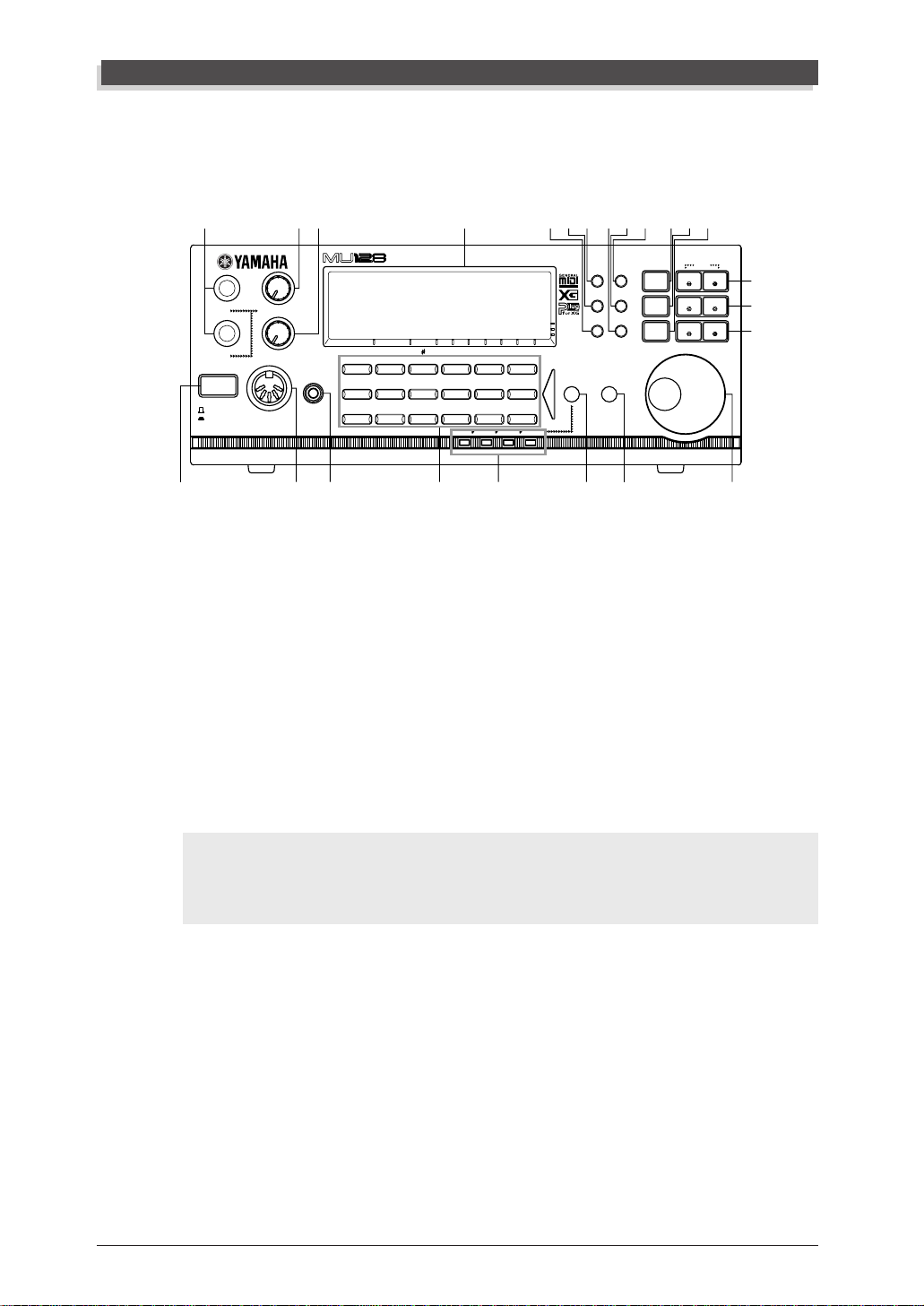
Front Panel
4
1
STAND BY
ON
1
2
2
39A8:
TONE GENERATOR
A/D INPUT
PART VOL EXP PAN
VOLUME
Synth effects
PHONESMIDI IN A
BANK/PGM
Chrom.perc.
Piano
Ensemble Brass Reed Pipe Synth lead Synth pad
5 6 JLK
REV CHO VAR KEY
MU PLG-1 PLG-2 PLG-3
7 N
StringsBassGuitarOrgan
DrumModel excl.SFXPercussiveEthnic
XG
TG
300
PERFORM
SELECT
PLAY EDIT
UTIL EFFECT
MODE EQ
B
PART GROUP
BCM
DEF
ALL
MUTE/
SOLO
ENTER
EXIT
PART
SELECT
VALUE
PART
SELECT
VALUE
1 A/D INPUT 1, 2 jacks
For connection of a microphone, electric guitar or other electronic instruments
(1/4” mono).
2 A/D INPUT VOLUME control
For control of the level of the A/D inputs.
3 VOLUME control
For adjusting the overall v olume of the MU128. (This does not affect the exter nal signal received via the rear panel INPUT jacks.).
G
H
I
14
4 STAND BY/ON switch (Power Switch)
Pressing this turns the power on and off (stand by).
1
CAUTION
Even when the switch is in the “STAND BY” position, electricity is still flowing to the
instrument at the minimum level. When you are not using the MU128, make sure you
unplug the AC power adaptor from the wall AC outlet.
5 MIDI IN A terminal (front panel)
For connection to other MIDI devices, such as a MIDI ke yboard or sequencer.
When the HOST SELECT switch is set to “MIDI,” this receives MIDI data for
controlling Parts set to receive over channels A01 - A16. When the HOST
SELECT switch is set to “Mac,” “PC-1,” or “PC-2,” it transmits the received
MIDI data to the TO HOST terminal. The front panel MIDI IN A terminal can
be selected for operation in the Utility mode (page 157). A rear panel MIDI
IN-A terminal is also provided; however both the front and rear panel terminals cannot be used simultaneously.
6 PHONES jack
For connection to a set of stereo headphones (stereo mini pin).
MU128of the MU90R

The Controls of the MU128
7 Voice Category buttons
For selection of basic Voice categories. Use these b uttons to call up the desired
Voice category in the Multi Play mode (Single Part controls; page 59) or in the
Performance Play mode (Single Part controls; page 72), then select a specific
Voices from the category by using the [VALUE -/+] buttons or data dial.
(page 43.)
8 MODE button
For calling up the Sound Module mode display. (page 170.)
9 PLAY button
For entering the Play mode and switching among the different Play displays.
(pages 41, 47.)
0 EDIT button
For entering the Edit mode. (pages 58, 69.)
A UTIL (UTILITY) button
For entering the Utility mode. (page 156.)
B EFFECT button
For entering the Effect Edit mode. (page 146.)
English
C EQ button
For entering the EQ Edit mode. (page 155.)
D MUTE/SOLO button
Pressing this alternately mutes or solos the selected Part. (page 95.)
E ENTER button
For calling up menu items in the display and for executing certain functions
and operations. Double-clicking this (pressing it twice quickly) calls up the
Show MIDI data function. (page 171.)
F EXIT button
For leaving various display pages and returning to previous displays. Also for
canceling certain functions and operations.
G PART -/+ buttons
For selecting different Parts. In the Effect Edit mode, these can be used to
switch among the different effects. Pressing these together alternately switc hes
between All Part and Single Part control. (page 61.)
H SELECT </> buttons
For selecting the various menu items, parameters and controls on the display.
I VALUE -/+ buttons
For changing the value of a selected parameter or control.
MU128 MU90R
15

The Controls of the MU128
Hint
You can rapidly move through the values by holding down one of the [VALUE
buttons. Y ou can move even more rapidly by holding down one button and then pressing and holding down the other . For example, to rapidly advance (increase) the value,
hold down the [VALUE
-
] button.
J Data dial
For rapidly adjusting/changing values of the selected function or parameter.
Rotate this clockwise to increase the value.
K SELECT button
For switching among the internal Voices of the MU128 and the Voices of any
installed optional XG Plug-in boards (page 174). (This applies to tone generator type boards only; effect type boards are selected by a different method.)
Press this repeatedly to select the desired board and its Voices. The appropriate LED flashes briefly and the corresponding icon for the board appears in the
LCD. (This button has no effect unless a tone generator type plug-in board is
installed.) (page 178.)
+
] button and simultaneously press and hold down the [VALUE
-/+
]
L PART GROUP button
For switching among the Part groups. Press this repeatedly to select the desired Part group (A, B, C, or D).
M Display
This back-lit LCD displays all necessary operation information for the MU128.
N LEDs
These indicate how many plug-in boards are installed. The MU LED indicates
the MU128 itself and its built-in Voices and remains lit. PLG-1, PLG-2, and
PLG-3 are lit according to the number of XG Plug-in boards installed. When
using the SELECT button to select a board, the corresponding LED flashes
briefly.
During playback of song data (from a sequencer, etc.), these flash to indicate
usage of the various sound sources.
16
MU128of the MU90R
The Controls of the MU128
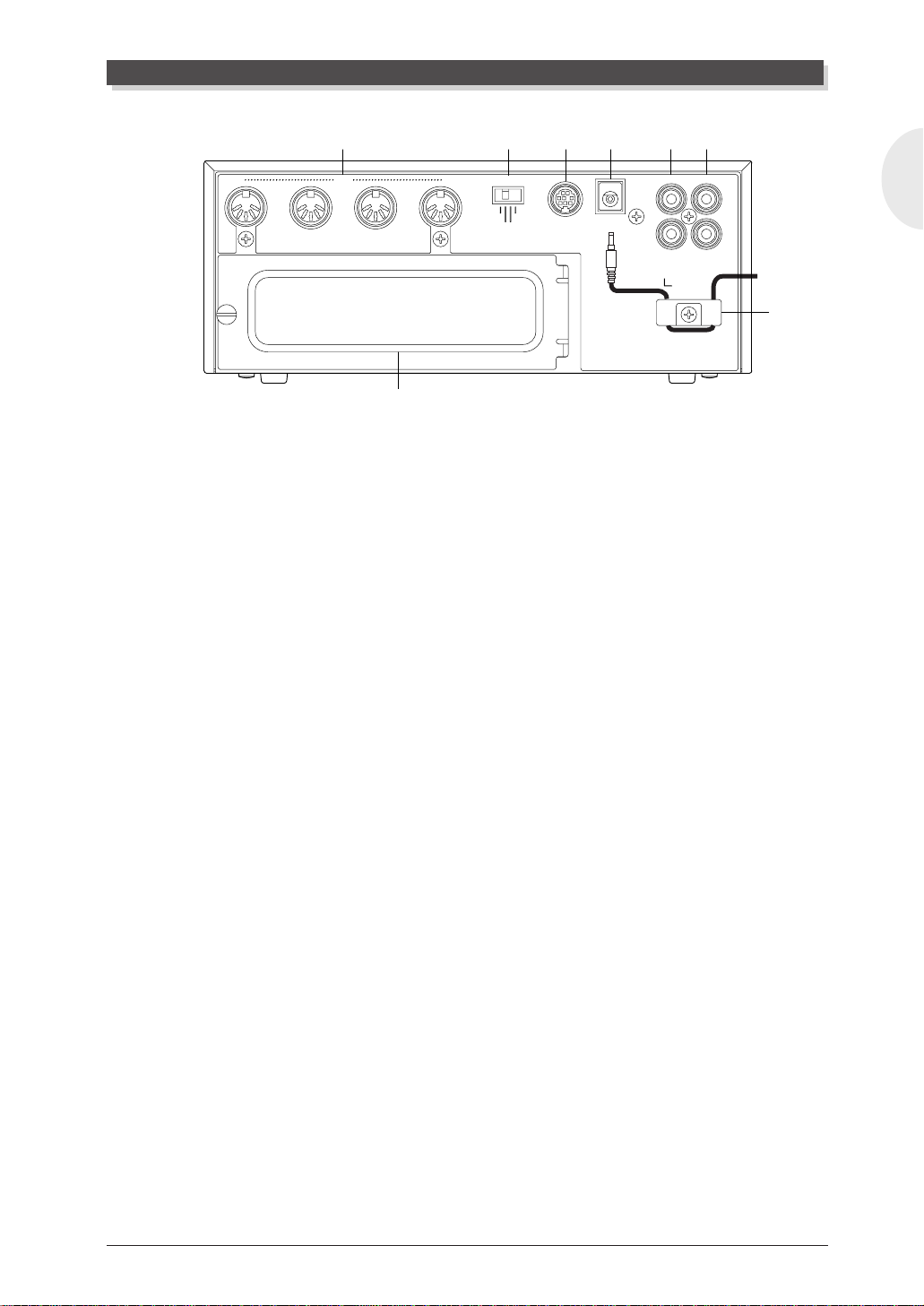
Rear Panel
1 MIDI terminals
For connection to other MIDI devices, such as a MIDI keyboard, tone generator, or sequencer, or to a computer that has a MIDI interface.
• MIDI IN-A terminal
When the HOST SELECT switch is set to “MIDI,” this receives MIDI data for
controlling Parts set to receive over channels A01 - A16. When the HOST
SELECT switch is set to “Mac,” “PC-1,” or “PC-2,” it transmits the received
MIDI data to the TO HOST terminal. The front and rear panel MIDI IN-A
terminals cannot be used simultaneously. The rear panel MIDI IN-A terminal
can be selected for operation in the Utility mode (page 157).
THRU
OUT IN-A IN-B
1
MIDI
8
2 3 4 6 7
HOST SELECT
Mac
MIDI
PC-2 PC-1
TO HOST DC IN
OUTPUT INPUT
L
R
SER NO.
English
5
• MIDI IN-B terminal
When the HOST SELECT switch is set to “MIDI,” this receives MIDI data for
controlling Parts set to receive over channels B01 - B16.
• MIDI OUT terminal
This is for transmitting data to another MIDI device, in the case of sending
bulk data to a computer or MIDI data storage device (when the HOST SELECT switch is set to “MIDI”). It also can be used for outputting the data
received via the TO HOST terminal, letting you connect other MIDI instruments and use the MU128 as a MIDI interface for your computer (when the
HOST SELECT switch is set to “Mac,” “PC-1,” or “PC-2”).
• MIDI THRU terminal
This is for outputting the data received via the MIDI IN-A terminal as is, without any additional data generated by the MU128 itself. This is commonly used
for “daisy-chain” connection of other MIDI instruments.
2 HOST SELECT switch
For selecting the type of host computer. (page 35.)
MU128 MU90R
17

The Controls of the MU128
3 TO HOST terminal
For connection to a host computer that does not have a MIDI interface. ( page
36.)
4 DC IN jack
For connection to the PA-6 AC power adaptor.
1
WARNING
Use ONLY a Yamaha PA-6 AC Power Adaptor (or other adaptor specifically recommended by Yamaha) to power your instrument from the AC mains. The use of other
adaptors may result in irreparable damage to both the adaptor and the MU128.
1
CAUTION
When connecting the AC power adaptor, first make sure that the MU128 is turned off
(set to ST AND BY). Next, connect one end of the power adaptor to the DC IN jack on
the MU128, and connect the other end to an appropriate AC outlet.
5 Power cord hook
Use this to secure the AC power adaptor’s cord and connector to the MU128,
to prevent accidental disconnection. Plug the connector into the DC IN jack,
then wrap the cord inside both ends of the hook.
6 OUTPUT L, R jacks (Left, Right)
For connection to a stereo amplifier/speaker system.
7 INPUT L, R jacks (Left, Right)
These are for connection to external sound sources, such as CD players, cassette decks, etc. Neither the front panel VOLUME control nor the built-in
effects and equalizer of the MU128 have any effect on the input sound.
8 XG Plug-in Board expansion bay
This bay accommodates up to three XG Plug-in Boards. To install a board,
first remove the expansion bay cover (page 179). Since the screw is tightened
securely at the factory, you may need to use a screwdriver to loosen it at first.
Normally, it can be fastened and removed simply by using your fingers.
18
MU128of the MU90R

The MU128 — What It Is and What It Can Do
The MU128 — What It Is and What It Can Do
What It Is...
The MU128 is a full-featured and easy-to-use tone generator, that provides an
unprecedented wealth of Voices and expressive sonic control. It features full
General MIDI Level 1 compatibility . It also pro vides XG compatibility , with an
huge total of 1149 Voices and 37 drum kits.
The MU128 has 128-note polyphony and is 64-Part multi-timbral. In other
words, the MU128 has 64 different Parts, each with its o wn Voice, so that up to
64 different Voices can be sounded simultaneously.
Additional A/D P arts let you connect up to two e xternal signals — such as a
microphone, electric guitar or CD player — and mix them with the MU128’s
Voices.
Although Voices cannot be directly edited, the various P art controls and Edit
mode give you tools for transforming or customizing the sound of the Voices.
What’ s more, the MU128 has a built-in multi-ef fect processor , with se ven independent digital effect “units” for enhancing the sound.
The MU128 also features a special Performance mode, in which four Parts
are played simultaneously over a single MIDI channel. Connected to a MIDI
keyboard, this effectively gives you four tone generators in one. The MU128
gives you 100 factory-programmed Preset Performances plus 100 Internal Per formance locations for storing your own original Performances.
English
About General MIDI
General MIDI is a new addition to the worldwide MIDI standard. MIDI, as
you know, stands for Musical Instrument Digital Interface, and makes it
possible for various electronic musical instruments and other devices to “communicate” with each other. For example, by connecting a sequencer to the
MU128’s MIDI IN terminal, you could play back a song on the sequencer
using the Voices of the MU128.
So, where does General MIDI fit in all of this? One of the most important
features of General MIDI is in the standardization of Voices. This means that a
song recorded in the General MIDI format can be played back on any General
MIDI compatible tone generator and sound just as the composer intended. For
example, if there is an alto sax solo in the song, it will be played by an alto sax
Voice on the General MIDI tone generator (and not by a tuba or harpsichord!).
Since the MU128 is fully compatible with General MIDI, you can take advantage of the vast wealth of musical material recorded in that format.
MU128
19

The MU128 — What It Is and What It Can Do
About XG
The new XG format is an extension of General MIDI, and provides a number of
significant improvements and enhancements. XG-compatible song data takes
advantage of the extensi ve MIDI control and built-in ef fects of the MU128 (and
other MU-series instruments).
To take greatest advantage of the powerful capabilities of XG, we recommend using XG-compatible instruments and software. For example, XG-compatible keyboards such as the Yamaha CBX-K2 keyboard and software giv e you
direct controls for accessing the full expressive potential of the MU128’s XG
Voices and the XG-related parameters.
What It Can Do...
Here are a few ideas on how you can use the MU128. The list below is not
comprehensive, but is meant to be a general guide to the possibilities and provide a starting point or springboard for your own creativ e ideas and explorations.
Using W ith MIDI Keyboard
Use the MU128 as supplementary tone generator with your MIDI keyboard
and play the Voices of both instruments in a layer together. Or, use the
convenient Performance mode, and pla y four Voices on the MU128 at once.
You can split the four Voices across the keyboard, playing each from a different register. Or you can create sophisticated velocity splits, in which a
different Voice is heard depending on how strongly you play the keyboard.
Or use keyboard and velocity splits together for even greater flexibility.
Using W ith a Computer or Sequencer
Home Studio Setup
The MU128 integrates instantly and easily into any existing setup. If you have a
MIDI keyboard, computer and sequencing software, the MU128 with its high-quality Voices and multi-timbral capabilities can expand your home studio system.
Carry It With You
If you have a laptop computer (and sequencing software), simply connect the
MU128, plug in some headphones and you’ve got a complete, high-powered
music making system that’ s ready to go wherever you go. Use it for composing,
arranging, practicing or making/playing demos for your band.
20
Use It on a Gig
Similarly , you can connect a laptop or a MIDI data filer and playback song data with
the MU128’s Voices. Plug a microphone into one of the A/D inputs and a guitar into
MU128an Do
The MU128 — What It Is and What It Can Do
the other, and you can mix your own live performance with the sequencer tracks.
Multimedia
Since it’s compatible with General MIDI and XG, the MU128 is a natural for
multimedia applications. Bring it with you to a presentation — since the computer interface is built-in to the MU128, it hooks up instantly and easily to the
computer’ s serial port or printer port, without the need for any other equipment.
About the Modes of the MU128
The MU128 has two main operating modes: Multi and Performance. In Multi
mode, the MU128 is a 64-Part multi-timbral tone generator; in Performance
mode, the MU128 effectively functions as four tone generators controlled
over a single MIDI channel.
Which mode the MU128 is in depends on the selected Sound Module
mode. If XG or TG300B are selected, the MU128 automatically sets itself to
the Multi mode. When PFM is selected, the MU128 is in the Performance
mode. (For information on selecting the Sound Module mode, see page 170.)
Each mode provides compatibility with different music software and hardware.
XG: This mode provides the full potential of the MU128, giving you
access to the 1149 XG Voices.
TG300B: This mode provides compatibility with the GM-B mode of the
TG300 Tone Generator.
PFM: This mode (Performance) lets you play four Voices simultaneously
over a single MIDI channel. (For more information on using the
Performance mode, see pages 38 and 70.)
English
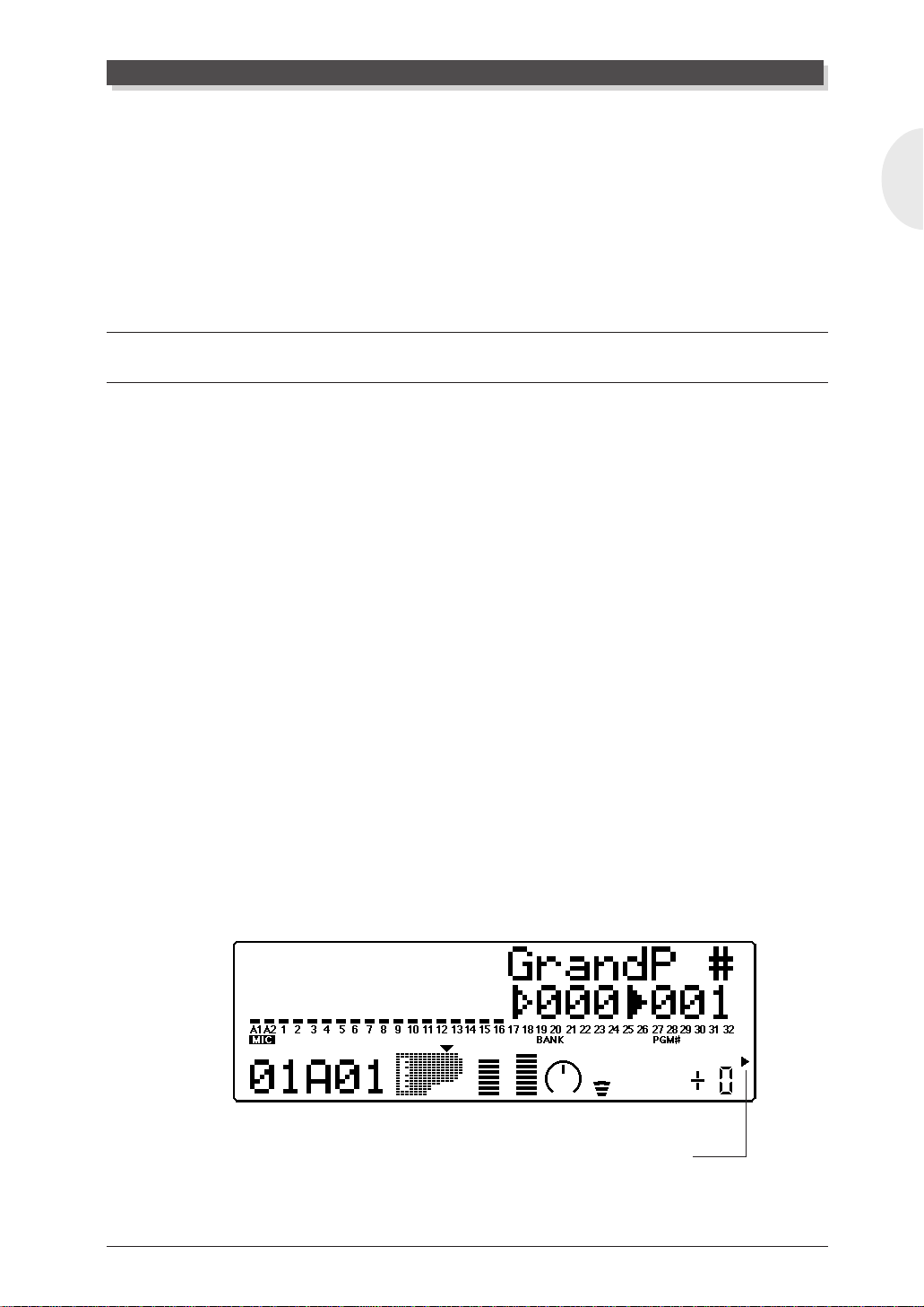
The bottom right of the display indicates the currently selected Sound Module mode.
XG
TG300B
PERFORM
Selected Sound Module mode.
MU128
21

The MU128 — What It Is and What It Can Do
NOTE
When set to the TG300B mode, the MU128 may not be able to play TG300-specific
song data with complete accuracy . However , MIDI data designed for other computer
music tone generators is compatible with the MU128.
Play Modes and the Part Controls
Once the operating mode of the MU128 is set (Multi or Performance), there
are two main ways you can use the MU128: playing and editing. In the Play
modes, you play the Voices; in the various Edit modes, you change their
settings.
Within the Play modes are the Part controls. These let you make basic
settings for the Parts. The Single Part controls allow you to make independent settings for each Part, while the All Part controls allow you to change
the overall settings of all Parts. (See pages 59 and 61 for more information.)
The MU128 has several diff erent Edit modes, each with various menus and
operations:
Part Edit Mode
The Part Edit mode allows you to change certain settings for each individual
Part, such as those of the Filter, EG (Envelope Generator), and many other
settings. The internal Voices can be sounded during editing, allowing you to
hear the effects of your edits.
Utility Mode
The Utility mode lets you set functions related to the overall operation of the
MU128, such as Master T une, display Contrast and reception of certain MIDI
messages that affect the entire instrument. Included also are miscellaneous
operations, such as sending bulk data to a data storage device, initializing of
the MU128 settings, and playing the special Demo song.
22
MU128an Do
Modes and Function Tree
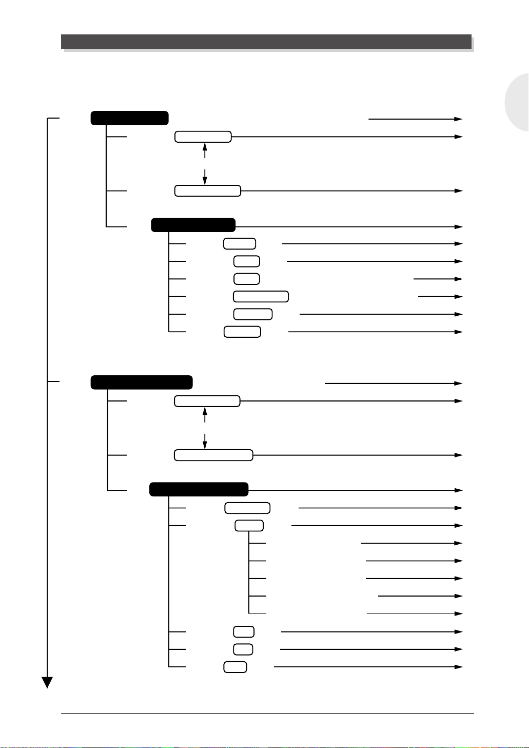
Modes and Function Tree
[PLAY]
Multi Play Mode
[SELECT </>] Multi Part Control
[SELECT </>] Multi All Part Control
[EDIT] Multi Part Edit Mode
( When the sound module mode is “XG” or “TG300B”)
[PART-++]
[SELECT <] Filter Edit [ENTER]
[SELECT </>] EG Edit [ENTER]
[SELECT </>] EQ Edit (Only when Normal Part is selected.) [ENTER]
[SELECT </>] Drum Setup Edit (Only when Drum Part is selected.)
[SELECT </>] Vibrato Edit [ENTER]
[SELECT >] Others Edit [ENTER]
[ENTER]
English
P. 170
P. 105
P. 109
P. 111
P. 111
P. 113
P. 116
P. 126
P. 117
P. 118
[PLAY]
Performance Play Mode ( When the sound module mode is ”PFM”)
[SELECT </>] Performance Control
[PART-++]
[SELECT </>] Performance Part Control
[EDIT] Performance Edit Mode
[SELECT <] Common Edit [ENTER]
[SELECT </>] Part Edit [ENTER]
[SELECT <] Filter Edit [ENTER]
[SELECT </>] EG Edit [ENTER]
[SELECT </>] EQ Edit [ENTER]
[SELECT </>] Vibrato Edit [ENTER]
[SELECT >] Others Edit [ENTER]
[SELECT </>] Copy [ENTER]
[SELECT </>] Store [ENTER]
[SELECT >] Recall [ENTER]
P. 170
P. 132
P. 134
P. 137
P. 137
P. 140
P. 141
P. 141
P. 141
P. 141
P. 141
P. 142
P. ??
P. 143
P. 145
MU128t Is and What It Can Do
23
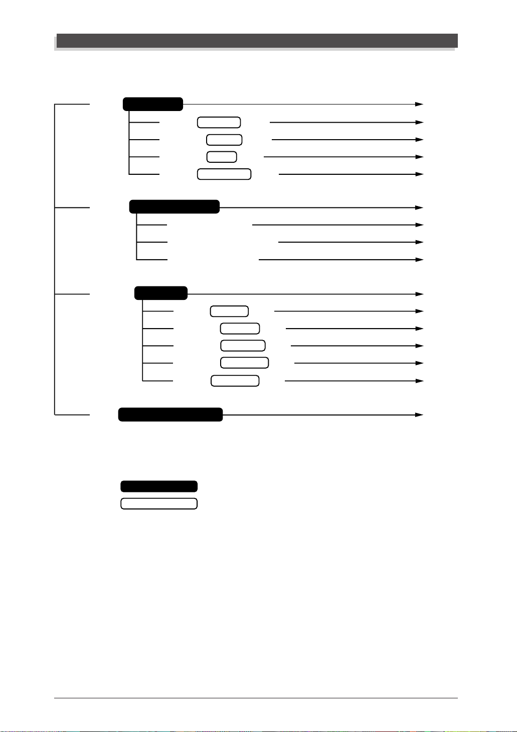
Modes and Function Tree
[UTIL]
[MODE]
[EFFECT]
Utility Mode
[SELECT <] System Setup [ENTER]
[SELECT </>] Dump Out [ENTER]
[SELECT </>] Initialize [ENTER]
[SELECT >] Demo Song Play [ENTER]
Sound Module Mode
[SELECT <] or [VALUE-] XG
[SELECT </>] or [VALUE+/-] TG300
[SELECT >] or [VALUE+] PFM
Effect Mode
[SELECT <] Reverb Edit [ENTER]
[SELECT </>] Chorus Edit [ENTER]
[SELECT </>] Variation Edit [ENTER]
[SELECT </>] Insertion 1 Edit [ENTER]
[SELECT >] Insertion 2 Edit [ENTER]
P. 156
P. 157
P. 162
P. 166
P. 169
P. 170
P. 170
P. 170
P. 170
P. 146
P. 147
P. 148
P. 149
P. 151
P. 151
[EQ]
Equalizer (Multi EQ) Mode
: Mode
: Submode
A slash mark ( / ) indicates that either button can be pressed.
(For example, SELECT < / > means that either < or > can be
pressed.)
A Plus sign ( + ) indicates that both buttons should be pressed
simultaneously. (For example, PART -+ + means that both
PART - and + should be pressed.)
P. 155
24
MU128

G
When using your MU128 for the first time, read through this
short section of the manual. It guides you step-by-step in
using many of the basic operations: setting the instrument up,
connecting it properly to other equipment, and — most importantly — playing it. It also introduces you to most of the
other, advanced features and operations of the instrument —
enabling you to quickly and effectively get the most out of
your new MU128.
UIDED
T
OUR
MU128 Guided Tour

Setting Up Y our MU128
Setting Up Your MU128
In this section, you’ll learn how to:
© Connect the MU128 in the most basic setup — with a MIDI keyboard and
an external amplifier/speaker system.
Other setup examples are covered in later sections; for example, setting up
for use with a computer is on page 35. Once you’ve set up the MU128, we
urge you to play the Demo song (page 30) and hear what the instrument is
capable of.
What You’ll Need
☛ The MU128 and the included PA-6 power adaptor.
☛ A MIDI keyboard, electronic piano, or any instrument that can output
MIDI data.
☛ An amplifier/speaker system, preferably stereo. Alternately, you can use
a set of stereo headphones.
☛ Audio connecting cables.
☛ A MIDI cable.
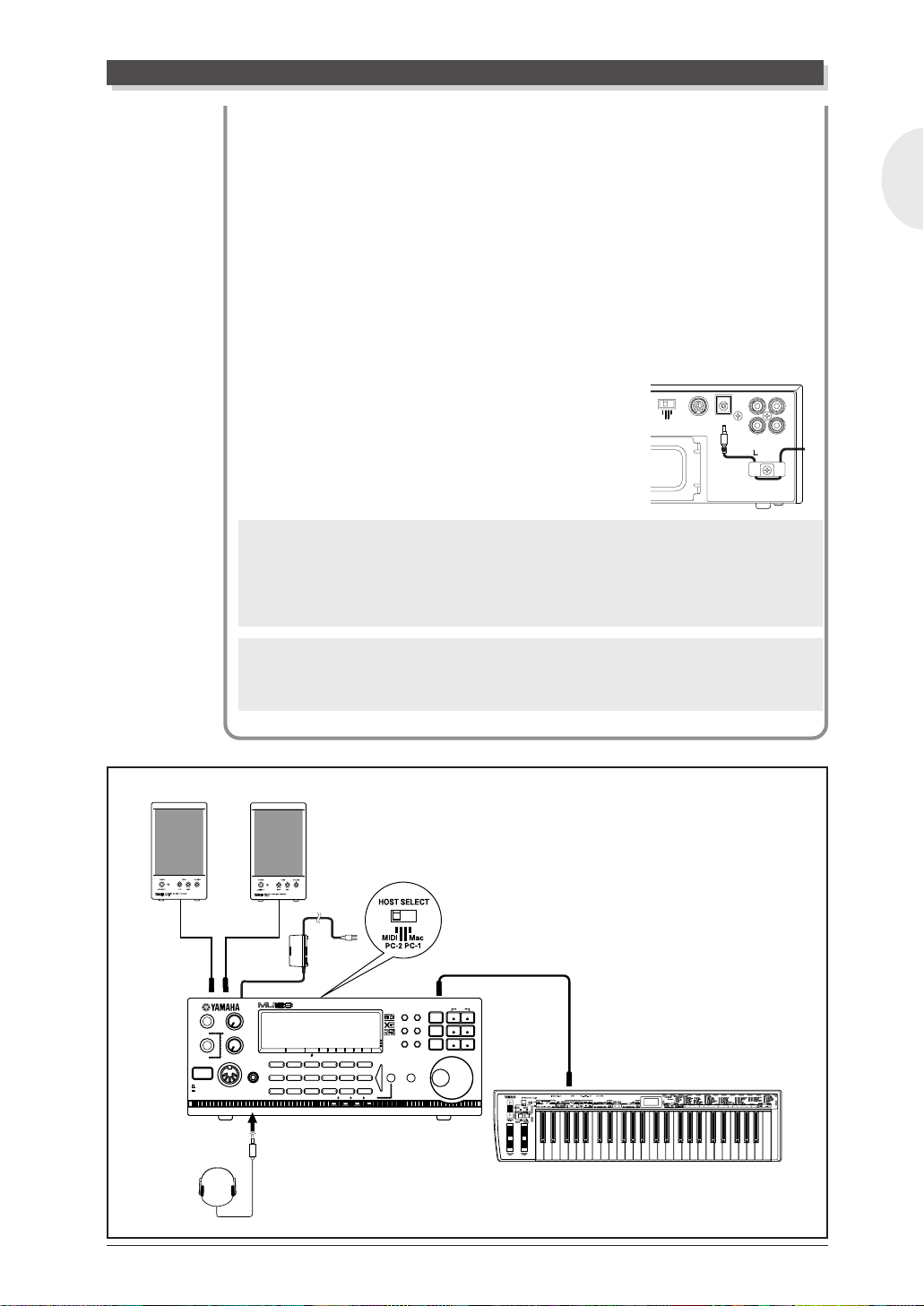
Making the Connections
1
CAUTION
Before making any connections, turn all related equipment off, and make sure the
MU128 power adaptor is not connected to an electrical outlet.
Operation
1 Connect the MIDI cable.
Connect the MIDI OUT terminal of the MIDI keyboard to the
MIDI IN-A of the MU128 (as shown in the illustration).
NOTE
The MU128 features both rear and front panel MIDI IN-A terminals. Since both
cannot be used simultaneously, you must determine which of them you will use.
At the factory, the MIDI IN-A is set for rear panel operation. This can be changed
to front panel operation in the Utility mode’s System parameters (page 157).
2 Connect the audio cables.
Connect the R and L OUTPUT jacks of the MU128 to the
appropriate inputs on the amplifier speaker system (as shown in
the illustration).
26
MU128 Guided Tour
Setting Up Y our MU128
• If you are using stereo headphones, connect them to the front
panel PHONES jack.
3 Set the HOST SELECT switch.
Set this rear panel switch to MIDI (see illustration).
4 Connect the AC power adaptor.
Plug the DC output cable of the PA-6 into the DC IN terminal
on the rear panel, then plug the adaptor into an appropriate
electrical outlet.
SER NO.
OUTPUT INPUT
L
R
• Wrap the DC output cable of the adaptor
around the cable clip (as shown at right) to
HOST SELECT
MIDI
PC-2 PC-1
Mac
TO HOST DC IN
prevent accidental unplugging of the cable
during operation.
1
WARNING
• Use ONL Y a Yamaha PA-6 AC Power Adaptor (or other adaptor specifically recommended by Y amaha) to power your instrument from the AC mains. The use of
other adaptors may result in irreparable damage to both the adaptor and the
MU128.
English
OUTPUT
1
CAUTION
• Unplug the AC Power Adaptor when not using the MU128, or during electrical
storms.
Amplifier
Speaker System
R
L
1
2
STAND BY
ON
PHONES
DC IN
A/D INPUT
VOLUME
PHONESMIDI IN A
TONE GENERATOR
PART VOL EXP PAN
BANK/PGM
Chrom.perc.
Piano
Ensemble Brass Reed Pipe Synth lead Synth pad
Synth effects
REV CHO VAR KEY
MU PLG-1 PLG-2 PLG-3
XG
TG
300
B
PERFORM
StringsBassGuitarOrgan
SELECT
DrumModel excl.SFXPercussiveEthnic
PLAY EDIT
UTIL EFFECT
MODE EQ
PART GROUP
MUTE/
SOLO
ENTER
EXIT
MIDI IN-A
ALL
PART
PART
SELECT
SELECT
VALUE
VALUE
MIDI CABLE
MIDI OUT
MU128 Guided Tour
MIDI Keyboard
27

Setting up your MU128
Now that you’ ve set up the MU128, we ur ge you to go on to the next section,
turn on the instrument, and play the Demo song (page 30) to hear what the
instrument is capable of. If you need information on setting up the MU128
for a different type of system, refer to “Setting Up the MU128 in Your
Music System” on page 32.
28
MU128 Guided Tour
Powering up
Powering Up
Admittedly this is a simple operation, but you should be careful to follow the
instructions below to avoid possible damage to your equipment and speakers.
Operation
1 Turn on the power of your MIDI keyboard.
2 Turn on the power of the MU128.
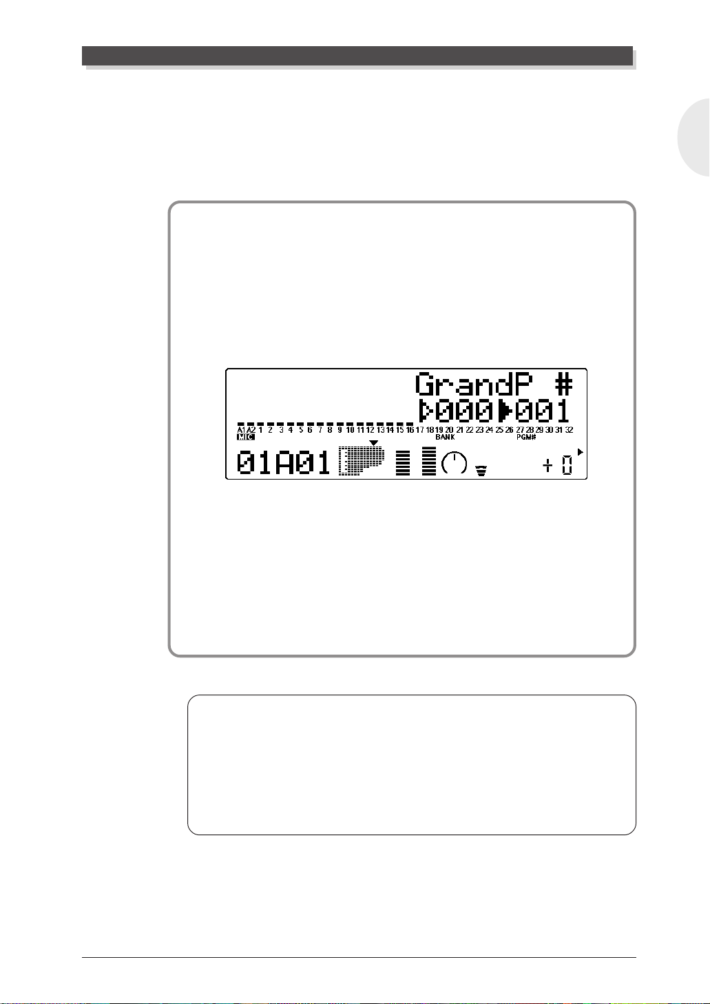
Press the STAND BY/ON switch.
After the animated greeting display finishes, the following dis-
play appears:
English
3 Turn down all volume controls.
This includes the MU128 and any connected equipment.
4 Turn on the amplifier/speaker system.
5 Set the volume controls.
First, set the volume control on the MU128 to about the midway
position, then set the volume on the amplifier to a suitable level.
Powering Down
When you turn the power off, make sure to do it in the following order:
1) Amplifier/speaker system
2) MU128
3) Other connected equipment (MIDI keyboard, etc.)
This prevents possible damage to the speakers.
MU128 Guided Tour
29
Playing the Demo Song
Playing the Demo Song
Now that you’ve set everything up properly, try playing the built-in Demo
song. This showcases the high-quality Voices and the AWM2 tone generation system of the MU128. It also is an excellent demonstration of the 64part multi-timbral capacity and the various expressive controls and effects
that can be used simultaneously . Most importantly , the Demo song will gi ve
you an idea of how powerful the MU128 can be in your own MIDI/computer music setup.
NOTE
All System Setup and Multi Part Edit settings are initialized to their default values
when playing back the demo song. Save your important data to a computer or the
MDF3 MIDI Data Filer by using the Dump Out functions (page 162).
Operation
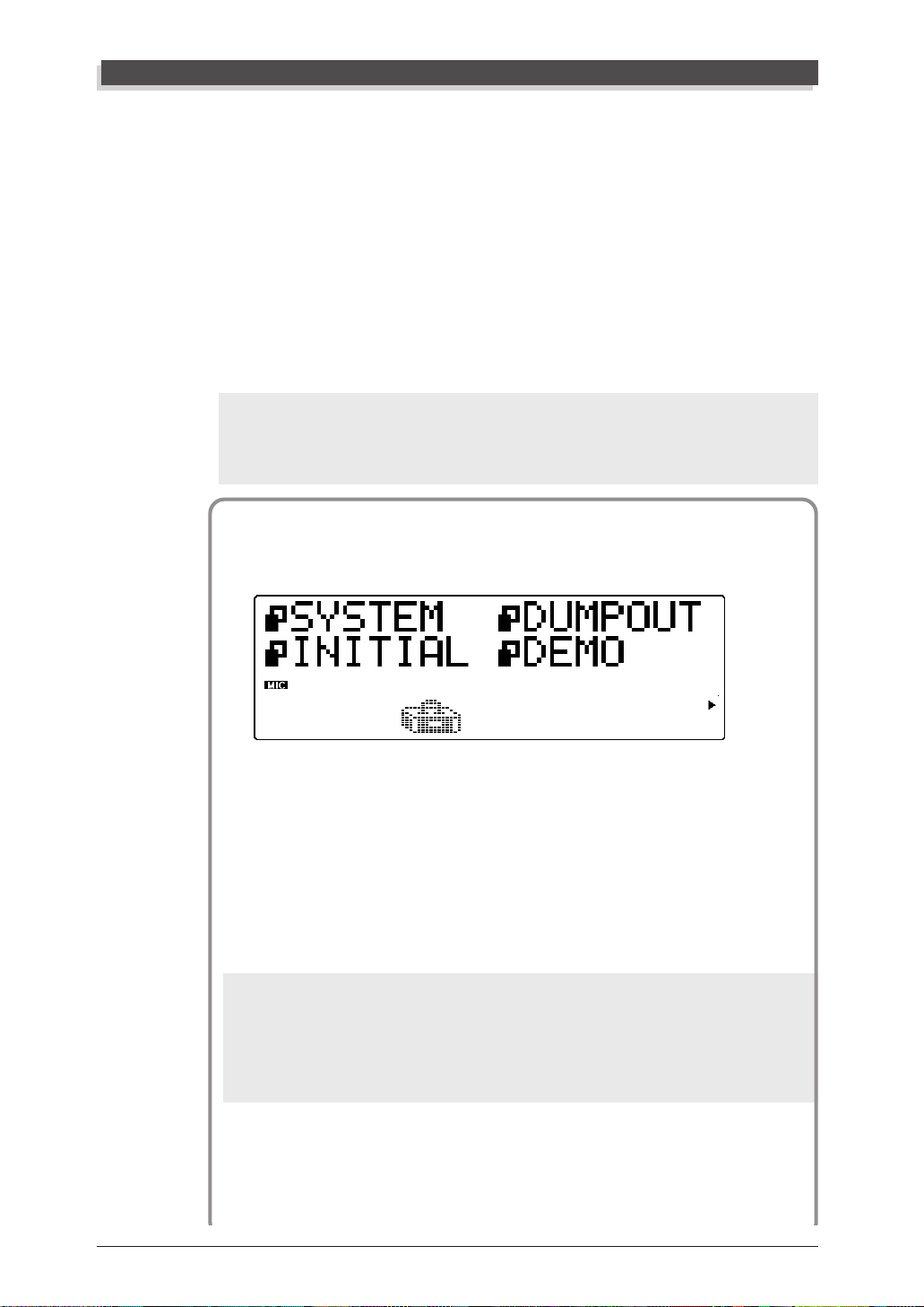
1 Press the [UTIL] button.
30
2 Select and open the DEMO menu.
Use the [SELECT </>] buttons to select “DEMO” (the menu
icon flashes), then press the [ENTER] button.
3 Start the Demo song.
Press the [ENTER] button. The Demo Song starts playing immediately and repeats indefinitely until stopped (in step 4 below).
NOTES
• During Demo Song playback, none of the panel controls (with the exception of
the [EXIT] button and the VOLUME control) can be used.
• In the Multi mode, the default setting for Variation Connection is Insertion. In
the Performance mode, the default setting differs depending on the selected
Performance.
MU128 Guided Tour

Playing the DemoSong
4 Stop playback of the song.
Press the [EXIT] button.
5 Exit from the Demo Song function.
Press the [EXIT] button again — twice to return to the Play
mode. (Or you can simply press the [PLAY] button.)
About the Demo Song
All instrument sounds and processing heard in the demo song were realized
exclusively with the Voices and effects of the MU128. It demonstrates just
how powerful and realistic sounding the MU128 can be on its own, as the
only tone generator in a MIDI sequencing system.
The demo song starts out with a soft orchestral introduction, using the rich
and realistic orchestra Voices, then swiftly segues into a hard rock section
showcasing fast and furious distorted guitar followed by jazz guitar and
overdriven guitar Voices. This breaks into a big band passage, starting with
a 40's style swinging sax section and continuing with a powerful full brass
arrangement. A rhythm and blues band, complete with an authentic
sounding organ and horn section, rounds out the demo, followed by a
luscious ambient/world music ending.
English
Make sure to read the display as the demo plays back — this shows the
names of some of the Voices used in creating this dynamic piece. Listen to
the demo often, as well — it’ll give you ideas and directions for interesting
paths to take as you use the MU128 in creating your own music.
Demo Song Credits
Programmed by Paul Lawley
Remixed by Graham Lee
Produced by XG Tokyo Office and Yamaha MusicSoft Europe
Data edited by Yasunori Ogawa
MU128 Guided Tour
31

Setting Up the MU128 in Your Music System
Setting Up the MU128 in Your Music System
As you learned in the section The MU128 — What It Is and What It Can
Do on page 19, the MU128 can be integrated into a variety of setups. It
would be impossible to cover all connection possibilities in a short manual
as this; howev er, the section belo w will help in quickly setting up the MU128
and using it in your system.
Connecting to MIDI Devices
The MU128 is equipped with MIDI IN, OUT, and THRU terminals, allowing you to use it in any MIDI system. Moreover, the two MIDI IN terminals
are independent 16-channel ports, effectively giving you two tone generators in one. Refer to the example that most closely matches your setup, then
read the Operation steps at the end of this section.
• MIDI keyboard
In this setup, you can play the sounds of the MU128 from the connected
keyboard.
MIDI
OUT
THRU
OUT IN-A IN-B
MIDI
IN-A
MIDI
TO HOST
HOST SELECT
MIDI
PC-2 PC-1
Mac
TO HOST DC IN
R
SER NO.
OUTPUT INPUT
L
MIDI Keyboard
NOTES
• Connect the MIDI OUT terminal of the keyboard or sequencer to the MIDI IN-A
terminal of the MU128.
• The MU128 features both rear and front panel MIDI IN-A terminals. Since both
cannot be used simultaneously , you must determine which of them you will use.
At the factory , the MIDI IN-A is set for rear panel operation. This can be changed
to front panel operation in the Utility mode’s System parameters (page 157).
32
MU128 Guided Tour

Setting Up the MU128 in Your Music System
• Hardware sequencer
In this setup, a hardware sequencer (such as the Yamaha QY700) is used.
The main advantage of such a setup is its portability.
MIDI
OUT
IN A
OUT BOUT A
FOOT SWRL/MONO
IN B
MIDI
PITCH ASSIGNABLE
SONG
VOICE
MAX
VOLUME
SHIFT
CAPS
OCT
OCT
DOWN
UP
ON
ORG
BASS
BASS
_
E FGABC
A
SECTION
B C D E F G H
OUTPUT
PATTERN
UTILITY
EFFECT
DISK
SHIFT F1 F2 F3 F4 F5 F6 SHIFT EXIT
CONTRAST
PLAYREC
EDIT
JOB
LOC 2LOC 1
(
#
#
E)D
#
CBA
A
F
C#D
G
b
b
b
B
G
A
DbE
c
S
%
&
?
!
MLK
D
MUSIC SEQUENCER
TRACK
TRACK
DOWN
UP
SOLOMUTE
REST
TIE
#
#
#
HGF
(
9)
5)
(
7
7
7
b
(
9)
b
b
5)
(
7
7
7
_
UTSRQPO#N
(9)
(9)
(9)
add9
6
7
M7
6
7
M7
M
OUT BOUT AIN B
IN A
MIDI
THRU
OUT IN-A IN-B
MIDI
IN-A
MIDI
TO HOST
HOST SELECT
Mac
MIDI
PC-2 PC-1 TO HOST DC IN
OUTPUT INPUT
L
R
-1 +1
789
YESNO
456
123
DEL
SPACE
a
b
(
13
)
JI
(11)
-
0
sus4
7
m7
OCT
OCT
3
3
#
DOWN
UP
(
11)
(13)
7
sus4
c
/
ZWV
YX
(9)
dim
mM7
add9
m7
aug
(b5
)
m
m6
m7
m7
SER NO.
• MIDI data storage device
This setup is used for backing up your important data — including original
Performances you’ve created, as well as settings you’ve changed in the Part
Edit, Effect, EQ, or Utility modes.
In this example, a Yamaha MDF3 MIDI Data Filer is used. To back up
data, connect the MIDI IN of the MDF3 to the MIDI OUT of the MU128. T o
restore the data to the MU128, connect the MIDI OUT of the MDF3 to the
MIDI IN-A of the MU128. Refer to the owner’s manual of the MDF3 (or
your particular data storage device) for specific operating instructions in
receiving or sending data.
English
MIDI IN
THRU
OUT IN-A IN-B
MIDI OUT
MIDI
HOST SELECT
Mac
MIDI
PC-2 PC-1 TO HOST DC IN
SER NO.
OUTPUT INPUT
L
R
MDF3
With the MDF3, you can also play compatible song data on the MU128
directly from the MDF3 itself, without the need of a sequencer. In this case ,
the MIDI OUT of the MDF3 should be connected to the MIDI IN-A of the
MU128.
MU128 Guided Tour
33

Setting Up the MU128 in Your Music System
• Computer equipped with a MIDI interface
In this setup, you can control the MU128 from a computer (using sequencing or other song playback software).
MIDI
MIDI
MIDI
IN-A
IN-B
TONE GENERATOR
PART VOL EXP PAN
BANK/PGM
REVCHO VAR KEY
Chrom.perc.
Piano
Ensemble Brass Reed Pipe Synth lead Synth pad
MU PLG-1PLG-2 PLG-3
MU128
OUT
StringsBassGuitarOrgan
DrumModel excl.SFXPercussiveEthnic
ALL
PLAY EDIT
MUTE/
PART
PART
SOLO
UTILEFFECT
SELECT
SELECT
ENTER
MODE EQ
XG
VALUE
VALUE
TG
300
B
EXIT
PERFORM
SELECT
PART GROUP
MIDI keyboard controller
1
A/D INPUT
2
VOLUME
Synth effects
STAND BY
PHONESMIDI IN A
ON
Connecting to a Macintosh computer
(with MIDI interface)
MIDI
MIDI interface
IN
MIDI
OUT
MIDI
OUT
Macintosh computer
Connecting to an IBM PC/AT compatible
computer (with MIDI interface)
MIDI
IN
MIDI
OUT1
MIDI
IBM-PC/AT or compatible
OUT2
HOST SELECT
MIDI Mac
HOST SELECT
MIDI Mac
computer
NOTES
• The MU128 features both rear and front panel MIDI IN-A terminals. Since both
cannot be used simultaneously , you must determine which of them you will use.
At the factory , the MIDI IN-A is set for rear panel operation. This can be changed
to front panel operation in the Utility mode’s System parameters (page 157).
• For Macintosh computers, you may have to change the MIDI interface clock setting on the application software to match your particular MIDI interface.
MIDI Data Flow
MIDI
OUT
MU128
MIDI
IN-B
MIDI
IN
MIDI
OUT
MIDI
OUT
MIDI Interface
TO HOST
CBX-K2
THRU OUT
Parts set to
receive over
channels
A1-A16
MIDI
IN-A
Parts set to
receive over
channels
B1-B16
34
MU128 Guided Tour

Setting Up the MU128 in Your Music System
NOTES
• Data received via the MIDI IN-A terminal plays back Parts set to channels A01 A16, and data received via the MIDI IN-B terminal plays back Parts set to channels B01 - B16.
• When the the HOST SELECT switch is set to MIDI, up to 32 Parts can be played
simultaneously.
Operation
1 Set the HOST SELECT switch to MIDI.
2 Connect the MU128 to the appropriate MIDI device.
Refer to the illustrations above. Use a standard MIDI cable (see
page ??).
3 Turn on the the connected device, then the MU128.
4 If you are using a computer, start up your music software, and
set up the appropriate options on the software for operation with
the MU128.
Connecting Directly to a Computer
English
The MU128 features a built-in host computer interface, allowing you to directly connect it to your computer — eliminating the need of installing a
special MIDI interface to your computer. The MU128 can be used with the
following computers: Apple Macintosh and compatibles, IBM PC/AT and
compatibles.
If your computer has a MIDI interface you may want to connect the
MU128 to it, rather than using the host computer interface on the MU128.
(See the section “Connecting to MIDI Devices” on page 32.)
Depending on the computer or interface used, set the HOST SELECT
switch to the appropriate setting: MIDI, PC-1, PC-2 (IBM and compatibles),
or Mac (Macintosh and compaibles). For information on the types of cables
that can be used for connection, see the section “MIDI/Computer Con-
necting Cables” on page 101.
Operation
1 Set the HOST SELECT switch on the rear panel of the MU128 to
the appropriate setting:
For IBM PC/AT or compatible computers: PC-2
For Macintosh computers: Mac
MU128 Guided Tour
35

Setting Up the MU128 in Your Music System
2 Connect the terminals as shown in the illustration below, using
standard computer cables*.
* Make sure to use the following commercially available standard cable types:
For IBM PC/AT or compatible computers: D-SUB 9-pin to Mini DIN 8-pin
(page 101)
For Macintosh computers:8-pin Macintosh Peripheral cable (page 101)
3 Turn on the power of the computer, then the MU128.
4 Start up your music software, and set up the appropriate options
on the software for operation with the MU128.
Connecting directly to an IBM PC/AT
compatible computer
HOST SELECT
MIDI Mac
PC-2 PC-1
MIDI keyboard controller
(Used as both tone generator
and MIDI interface.)
MU128
* Make sure to connect any external
MIDI devices to the MIDI IN-A terminal.
NOTES
• The MU128 features both rear and front panel MIDI IN-A terminals. Since both
• For Windows 95 users:
• For Macintosh computers, you should set the MIDI interface clock setting on the
STAND BY
ON
1
2
A/D INPUT
VOLUME
PHONESMIDI IN A
MIDI
OUT
MIDI
IN-A
TONE GENERATOR
PART VOLEXP PAN
BANK/PGM
Chrom.perc.
Piano
Ensemble Brass Reed Pipe Synth lead Synth pad
Synth effects
REVCHO VARKEY
MU PLG-1PLG-2PLG-3
StringsBassGuitarOrgan
DrumModel excl.SFXPercussiveEthnic
TO HOST
PLAY EDIT
UTILEFFECT
MODE EQ
XG
TG
300
B
PERFORM
SELECT
PART GROUP
ALL
MUTE/
PART
PART
SOLO
SELECT
SELECT
ENTER
VALUE
VALUE
EXIT
RS-232C
(DB-9)
IBM-PC/AT or
compatible computer
Connecting directly to a Macintosh computer
HOST SELECT
TO HOST
MIDI Mac
PC-2 PC-1
RS422
Macintosh computer
cannot be used simultaneously , you must determine which of them you will use.
At the factory , the MIDI IN-A is set for rear panel operation. This can be changed
to front panel operation in the Utility mode’s System parameters (page 157).
In order to use the TO HOST connection of the MU128 with your computer,
you’ll need to install special MIDI driver software (Y AMAHA CBX Driver for W indows 95). This driver is contained in the included CD-ROM.
application software to 1 MHz.
36
MU128 Guided Tour

Selecting and Playing the Performances
MIDI Data Flow
ECHO BACK = ON
MIDI
OUT
RS-232C
MIDI keyboard controller
MIDI
THRU OUT
MIDI data of the Port set in the Thru Port parameter
Port 1 Port 2 Port 3
Parts set to
receive over
channels
A1-A16
Parts set to
receive over
channels
B1-B16
IN-A
MU128
MIDI
IN-B
Parts set to
receive over
channels
C1-C16
TO HOST
Port 4
Parts set to
receive over
channels
D1-D16
NOTES
• Data received via the MIDI IN-A terminal is transmitted directly to the computer
(via the TO HOST terminal) without affecting the Parts of the MU128. To have
Parts on the MU128 respond to data received via the MIDI IN-A terminal (for
example, to hear sounds while entering data to the computer), make sure that the
MIDI Thru (or MIDI Echo) function on the music software is set to on. This function allows you to route data coming into the computer back out again.
• Providing your particular music software is capable of multi-port operation, you
can independently play all 64 Parts of the MU128 from your computer. With a
second multi-timbral tone generator , you can even expand this to a full 80 Parts.
To do this, connect the tone generator to the MIDI OUT terminal, then set the
Thru Port parameter (page 160) to a value of 5 or higher — giving you an additional 16 MIDI channels.
IBM-PC/AT or
compatible computer
ECHO BACK = ON
Macintosh computer
English
MU128 Guided Tour
37

Selecting and Playing the Performances
Selecting and Playing the Performances
As pointed out on page 21, the Performances of the MU128 let you play four
Voices together over one MIDI channel. These specially programmed Performances (100 Preset and 100 Internal) take full advantage of the MU128
dynamic Voices and flexible editing functions — giving you exceptionally
powerful and expressive sounds for live performance situations.
In this section, you’ll learn how to:
© Call up the Performance mode.
© Select and play Performances.
© Change the play mode display to suit your preference.
Calling Up the Performance Play Mode and
Playing the Performances
Operation
1 Press the [MODE] button.
2 Select “PFM” (PERFORMANCE) in the display.
Use the [SELECT </>] buttons, [VALUE -/+] buttons or data
dial.
XG
TG300B
PERFORM
Indicates Performance mode.
The Performance mode setting is also shown by the arrow at the
bottom right of the display.
NOTE
For more information on the sound module modes, see page 170.
38
MU128 Guided Tour

Selecting and Playing the Performances
3 Press the [PLAY] button to go to the Performance Play mode.
You can press the [EXIT] button for this as well.
“All” and keyboard player icon indicate All Part display of
Performance Play mode.
If the All Part display above (with the keyboard player icon) is not
shown, press both [PART-/+] buttons simultaneously.
4 Select the desired bank of Performances — Preset or Internal.
Use the [SELECT </>] buttons to select the Bank parameter,
then use the [VALUE -/+] buttons to select the desired bank,
Preset (Pre) or Internal (Int).
• Preset bank
English
• Internal bank
MU128 Guided Tour
39

Selecting and Playing Individual V oices
5 Select the desired Performance.
Use the [SELECT </>] buttons to select the Program Number
parameter, then use the [VALUE -/+] buttons or data dial to
select the desired Performance number.
Performance number
6 Play the connected MIDI keyboard.
Make sure that your keyboard is transmitting over MIDI channel
1. (Refer to the owner’s manual of that instrument if necessary.)
If you’ve carefully followed all instructions up to now, the “level
meter” bars in the display should move — and you should be
able to hear the sound of the MU128 as you play.
40
The “level meter” bars indicate the “level” (velocity) of the incoming MIDI data.
Go on to select other Performances in the same bank and play those
as well. To try out Performances in the other bank, return to step #4
above.
MU128 Guided Tour

Selecting and Playing Individual Voices
Changing the Play Mode Display
The MU128 lets you view the Parts of the Performance in two ways, depending
on your preference.
Press the [PLAY] button repeatedly. Each press of the [PLAY] button switches
between the two displays below.
Performance number and name are indicated.
Voice names which make up the Performance are indicated.
English
MU128 Guided Tour
41

Selecting and Playing Individual V oices
Selecting and Playing Individual V oices
The MU128 has a stunningly huge variety of Voices — a total of 1342. In
this section, you’ll select and play Voices in the XG mode, which features
1149 different Voices.
In this section, you’ll learn how to:
© Call up the XG mode.
© Select Voice banks and Voices from the panel controls.
© Change the Play mode display to suit your preference.
© Select and play Voices from a MIDI keyboard.
Calling Up the XG Mode
Operation
1 Press the [MODE] button.
2 Select “XG” in the display.
Use the [SELECT </>] buttons, [VALUE -/+] buttons or data
dial.
XG
TG300B
PERFORM
Indicates XG mode.
The XG mode setting is also shown by the arrow at the bottom right
of the display.
42
3 Press the [PLAY] button to go to the Play mode.
You can press the [EXIT] button for this as well.
MU128 Guided Tour

Selecting and Playing Individual Voices
About the Modes — Multi and Performance
The MU128 has two main operating modes: Multi and Performance. You used
the Performance mode earlier when playing Performances — playing four
Voices over one MIDI channel. The Multi mode is primarily used in sequencer
and computer music applications, since it allows you to play all 64 Parts
independently over different MIDI channels.
Which mode the MU128 is set to depends on the selected Sound Module
mode. The XG andTG300B settings are all Multi mode. When PFM is selected,
the MU128 is in the Performance mode.
Selecting Voice Banks and Voices From the Panel
There are two basic methods of selecting Voices and banks: one using the
Voice Category buttons to automatically select specific Voices according to
their instrument groups, and the other letting you manually select the Voice
bank and Voice. (Voices/banks can also be selected remotely from a MIDI
device; see page 48.)
Selecting Voices with the Voice Category Buttons
English
This convenient method lets you select Voices according to the general instrument groups to which they belong, automatically selecting the appropriate program number and bank for you.
Operation
1 Select a Part by using the [PART -/+] buttons.
Part number
2 Press the Voice Category button corresponding to the desired
Voice group (Piano, Guitar, Bass, etc.).
The lowest numbered bank/Voice in the category is
automatically selected.
MU128 Guided Tour
43

Selecting and Playing Individual V oices
STAND BY
ON
TONE GENERATOR
1
A/D INPUT
PART VOL EXP PAN
2
VOLUME
PHONESMIDI IN A
BANK/PGM
Chrom.perc.
Piano
Ensemble Brass Reed Pipe Synth lead Synth pad
Synth effects
REV CHO VAR KEY
StringsBassGuitarOrgan
DrumModel excl.SFXPercussiveEthnic
MU PLG-1 PLG-2 PLG-3
XG
TG
300
PERFORM
SELECT
PLAY EDIT
UTIL EFFECT
MODE EQ
B
PART GROUP
MUTE/
SOLO
ENTER
ALL
PART
PART
SELECT
SELECT
VALUE
VALUE
EXIT
Voice Category buttons
For example, when the [Guitar] Voice Category button is pressed,
bank 000/Voice 025 [NylonGt#] is selected as shown below.
The following list briefly describes the characteristics of the Voices for each
Voice Category button.
Piano: Conventional piano sounds, such as acoustic piano and electric
piano.
Chrom.perc.: Chromatic (pitched) percussion sounds, such as marimba and
vibraphone.
Organ: Various organ sounds, such as rock organ, pipe organ and
accordion.
Guitar: Guitar sounds, such as acoustic guitar and distorted guitar.
Bass: Bass and wood bass.
Strings: Stringed instruments, such as violin and cello. Also includes
other orchestral sounds, such as contrabass, harp and timpani.
Ensemble: Strings ensemble sounds.
Brass: Various brass instruments, such as trumpet and trombone, as
well as brass ensemble sounds.
Reed: Reed instrument sounds, such as saxophone and clarinet.
Pipe: Air reed instruments, such as flute, recorder and shakuhachi.
Synth lead: Synthesizer lead sounds.
Synth pad: Synthesizer pad sounds.
Synth effects: Various synthesizer sound effects and miscellaneous pitched
sounds.
Ethnic: World, ethnic and folk music instrument sounds.
Percussive: Percussion sounds.
SFX: Special sound effects.
Model excl.: Voices belonging to the MU100 Model Exclusive Voice bank.
Drum: Drum and SFX Kits.
44
NOTE
The V oice Category buttons can also be used to select Voices on an optional Plugin board (when it has been selected first with the [SELECT] button). Depending on
the board, however, certain categories may not be available. Also, the Model
excl. category features the original Voices of the board, which do not conform to
the GM standard.
MU128 Guided Tour

Selecting and Playing Individual Voices
3 Use the [VALUE -/+] buttons or data dial to select the desired
Voice from within the current category.
The selected bank and Voice numbers start from the lowest
number and “wrap around” at the beginning and end.
Try selecting different Voices for the other Parts using the same
operation.
Details
The MU128 features two different Voice maps: MU Basic and MU100 Native.
■
MU Basic — This V oice map maintains compatibility with the widest range of XG
tone generators.
■
MU 100 Native — This V oice map (selected as the default at the factory) includes
the upgraded Voices and Voices utilizing new waveforms not included on older
XG tone generators.
These two V oice maps have the same order and number of the V oices. However , the
actual sounds and overall balance may differ for each map when playing back identical song data, since the actual character of some of the Voices differs greatly.
When playing back song data created on or for other XG tone generators, try switching
between the two different maps to achieve the optimum playback condition for the
song.
The map setting can be changed in the Utility mode’s System parameters (page
161).
The MU128 includes additional Voices for both of the two maps that are not included on the MU100.
English
Manually Selecting Voice Banks and Voices
Operation
1 Select a Part.
Use the [PART -/+] buttons.
For this example, select Part 1. Press the appropriate button until
“01A1” appears in the PART section of the display.
MU128 Guided Tour
45

Selecting and Playing Individual V oices
2 Select the bank number.
Use the [SELECT </>] buttons to highlight the bank number
parameter (as shown below).
Instrument icon. Arrow at top
left of icon indicates bank
number is selected.
Bank number. Dark arrow
indicates bank number is
selected.
Program number.
3 Change the bank number.
Use the [VALUE -/+] buttons or data dial. Notice that the
bank numbers “jump” as they are selected — the MU128 skips
bank numbers that have the same Voice as bank “000.”
In the XG mode, several banks of Voices are available. Each bank
contains up to 128 different Voices, for a total of 1149 Voices.
4 Select the program (Voice) number.
Use the [SELECT </>] buttons to highlight the program
number parameter (as shown below).
46
Instrument icon, indicating the type of
Voice. Arrow at top right of icon indicates
program number is selected.
Bank number.
Program number. Dark arrow
indicates program number is
selected.
5 Change the program number.
Use the [VALUE -/+] buttons or data dial. In the example dis-
play below, Voice number 25 has been selected.
MU128 Guided Tour

About the Parts and Voices of the MU128
6 Play the Voice.
Play this new Voice from the connected MIDI keyboard. (Make
sure that the keyboard is transmitting on channel 1.) If you’ve
carefully followed all instructions up to now, the “level meter”
of the Part should move — and you should be able to hear the
sound of the MU128 as you play. Try selecting other Voice banks
and Voices and play them as well. Each Voice bank contains
some different Voices, some of which are variations, some
unique.
Details
• The MU128’s Voices and program numbers follow the GM (General MIDI) format. This means that you can select a Voice type by its number, then select
Voice variations by bank. For example, all the nylon guitar Voices are at program number 25.
• In the XG mode, the V oices are conveniently or ganized in the banks according
to their type. For example, V oices having stereo variations or brighter variations
are found in the “Stereo” and “Bright” banks, respectively. (See the “Sound List
& MIDI Data” booklet.)
• Though the MU128 skips over bank numbers with identical V oices (see step #3
above), it can be set to not skip bank numbers, if desired. (See page 161: Utility
mode/System/Display Bank Select.)
English
Refer to page 49 for more details about the MU128 voice organization.
Changing the Play Mode Display
The MU128 lets you view the Parts in three ways, depending on your preference.
Press the [PLAY] button repeatedly.
Each press of the [PLAY] button switches among the three displays below.
MU128 Guided Tour
47

About the Parts and V oices of the MU128
Selecting Voices From a MIDI Keyboard
You can also select Voices remotely from a connected MIDI keyboard.
Though the actual operation may differ depending on the keyboard used, the
general procedure is the same. These instructions also apply to use with a
computer. (Refer to the owner’s manual of your specific instrument or software for detailed instructions.)
Operation
1 Make the necessary settings on the keyboard.
Make sure that the keyboard is set to transmit over the desired
MIDI channel (the same as that of the selected Part), and that it
is set up to send Program Change messages.
2 Select a program number on the keyboard.
The Voice number and name on the MU128 will change, and
will be the same number as the program number you selected
on your keyboard.
Details
• Depending on what keyboard you are using to control the MU128, you may
need to be careful in selecting program numbers. The MU128’s program numbers start at “001,” but some keyboards have different numbering systems. For
example, some start at “0” — which means that selecting “25” on the keyboard
will select Voice 026 on the MU128.
• Parts 10, 26, 42 and 58 are reserved for playing drum “kits.” This is the default
factory setting for all of the Multi modes (XG and TG300B). For more information on drum Parts, see page 65.
48
MU128 Guided Tour

About the Parts and Voices of the MU128
About the Parts and V oices of the MU128
This section covers basic information about the Parts and Voices of the
MU128. It’ s not necessary to absorb all this information at once; yet if you
familiarize yourself with the concepts and details of this section, you’ll be
on your way to quickly mastering the operations of the MU128.
Parts
When the Sound Module mode is set to “XG” or “TG300B,” the tone generator section of the MU128 is fully multi-timbral and is made up of 64
independent Parts. By assigning different MIDI channels to each of these
64 Parts, you can play back complex song data having up to 64 separate and
simultaneous instrument tracks.
The Parts are designated by their Part group letters (A - D) and numbers
(01 - 16), as well as their individual Part numbers (1 - 64). The chart belo w
shows the Part numbers and their default MIDI channel settings.
Part Number
Part Group
MIDI Channel (default)
1
A01
A01
~
16
~
A16
~
A16
17
B01
B01
~
32
~
B16
~
B16
33
B16
B16
~
48
~
C16
~
C16
49
D01
D01
~
64
~
D16
~
D16
English
Voices
When the Sound Module mode is set to “PFM, ” the MU128 effecti vely functions as four tone generators, playing back up to four Parts over a single
MIDI channel.
Voices are the individual instrument sounds of the MU128. The MU128
features a total of 1342 Normal Voices and 47 Dr um Voice “kits.” (The
number of the Voices that can be used differs depending on the selected
Sound Module mode.) A Voice is actually comprised of one or two sound
elements, the “building blocks” of the sound.
Voice
Element 1 Element 2
MU128 Guided Tour
49

About the Parts and V oices of the MU128
Normal Voices and Drum Voices
The MU128 features two types of Voices: Normal and Drum.
Normal V oices
Normal Voices are pitched — in other words, the pitch of the Voice changes
according to the keys of the keyboard. A Normal Voice is made up of a
maximum of two sound elements. Voices having two elements include:
thick sounds that cannot be created by a single element, Voices in which the
sound changes depending on how strongly the keys are played, or layered
Voices in which two sounds are blended together (for example, piano and
strings). For details on how many elements specific Voices use, refer to the
Voice List of Normal Voices in the “Sound List & MIDI Data” booklet.
Drum V oices
The Drum Voice is a special Voice containing onl y drum and percussion
sounds, and each individual sound is assigned to a specific key of the keyboard (in the range of C#-1 — C5). For details on which drum sounds are
assigned to which keys, refer to the Drum Map charts in the “Sound List &
MIDI Data” booklet.
Maximum Simultaneous Sounds (Polyphony)
The maximum polyphony of the MU128, or the amount of sounds that can
be generated simultaneously, is 128. This number actually refers to the
amount of elements used. If you use many two-element Voices in your song
data, the number of available simultaneous sounds may be less than expected.
When the MU128 receives more MIDI data than can be played back with
the maximum polyphony, the earliest played notes will stop sounding to let
more recently received notes play. This is called “last note priority.”
Selecting the Voices
Voice selection on the MU128 is done by using three different numbers:
bank select MSB, bank select LSB, and the specific program number.
The bank select MSB and LSB values determine the Voice bank. A single
Voice bank can contain up to 128 Voices, each of which can be selected by a
program number.
The bank select MSB and LSB values are used differently depending on
which Sound Module mode is selected (as explained below).
50
MU128 Guided Tour

About the Parts and Voices of the MU128
Use of bank select MSB and LSB when the Sound
Module mode is set to “XG” or “PFM”
When the Sound Module mode is set to “XG” or “PFM,” the Voices are
divided into large groups, selectable by the bank select MSB values shown
below.
Bank select MSB = 0 — XG Voices
These are the Voices conforming to the GM System Level 1 standar d and its
expanded set of Voices. They can be played back to common effect for all
XG-compatible tone generators.
Bank select MSB = 48 — MU100 Exclusive Voices
Only the MU100 and MU128 contain these Voices. The order of the Voices
by program number assignments does not conform to the GM standard.
NOTE
Banks having an MSB value of 48 are used for original tone generator V oices which
do not conform to the GM standard in the XG V oice map. When playing back song
data using any of these Voices on an XG-compatible tone generator other than the
MU128 (or the MU100/100R), the Part using one of these Voices will not sound.
English
Bank select MSB = 64 — SFX Voices
These are sound effect Voices. They are included in the Normal Voices and
can be played back in pitch.
Bank select MSB = 126 — SFX Kits
These are also sound effects. They are included in the Drum Voices. A
different sound is assigned to each note number.
These are not available when the Sound Module mode is set to “PFM.”
Bank select MSB = 127 — Drum Kits
These are Drum Kits, and are not available when the Sound Module mode is
set to “PFM.”
When Sound Module mode is set to “XG” or “PFM”
(Drum and SFX Kits cannot be selected in “PFM”)
Normal Voices BankSelect MSB BankSelect LSB
Drum Voices
XG Voices
MU100 Exclusive Voices
SFX Voices
BankSelect MSB BankSelect LSB
Drum Kits
SFX Kits
0 0~127
48 0~120
64 0
127 0
126 0
MU128 Guided Tour
51

About the Parts and V oices of the MU128
The bank select LSB values apply only when the bank select MSB value is
set to 0 or 48 — these are used for selecting variation Voices. (Additional
MSB values are available when an XG Plug-in board is installed.)
For a bank select MSB value of 0, there are expanded sets of XG Voices
featuring Voice variations under general categories such as Stereo, Bright
and Sweep. Each of these variation banks is selected with a different LSB
value. The basic map for the 128 Voices in each variation bank is the same
as the GM System Level 1 standard, as found in the basic Voices (when
bank select LSB = 0). Therefore, you can select the desired Voice by specifying the program number, then select the desired type of Voice variation by
specifying the bank select LSB (as shown in the chart below).
For example, the basic Voice at program number 49 is “Strings1,” and
you can select variations on the Strings Voice by changing the bank select
LSB value while keeping the same program number. The variation bank
name (e.g., Stereo, Bright, etc.) indicates how the variation Voices differ
from the basic set of Voices.
Shaded portions in the chart below indicate Voices that are the same as
the basic ones in bank 0.
Bank Select LSB
Bank127 ~
:
Bank64 (Other Waves)
:
Bank40 (Tutti)
:
Bank3 (Stereo)
Bank1 (Key Scale Panning)
Bank0 (Basic GM
Voice set)
::: :
:::::
ElGrPno2PianoStr
:::::
ElGrPnoKGrndPnoK BritPnoK
El.Grand Strings1 GunshotGrandPno BritePno
3 49 12812
~
:
70s Str
~~
Orchestr
~~
S.Strngs
~~
~~
~~
~~
Ab
Program Number
Use of bank select MSB and LSB when the Sound
Module mode is set to “TG300B”
The bank select LSB value is set to a fixed number and the bank is selected
by changing the bank select MSB value. The bank select MSB is used to
select the variation Voices; however , unlike the XG Voices, individual banks
are not organized into specific variation categories.
52
MU128 Guided Tour

About the Parts and Voices of the MU128
When Sound Module mode is set to "TG300B"
Normal Voices BankSelect MSB BankSelect LSB
GM Voice set and variation set of Voices
C/M Voices*
Drum Voices
Drum Kits
* The C/M Voice set is included to provide multi-timbral compatibility for
Part Mode
The Part mode is used to determine whether the selected Part uses Normal
Voices or Drum Voices. It also lets you select a particular drum setup for
editing the Drum Voice. This is done in the Multi Part Edit mode (page
120).
Normal mode and Drum mode
The Part mode features two settings: Normal mode and Drum mode.
In the Normal mode (“normal”), Normal Voices can be selected.
In the Drum mode (“drum,” “drumS1 - S4”), Drum Voices can be selected.
English
0~41
126, 127
BankSelect MSB BankSelect LSB
computer music systems and song data that predate the GM System Level 1
standard.
NOTES
• When the Sound Module mode is set to “PFM,” the Part mode is fixed to normal
and cannot be changed. (The Part Mode parameter is not displayed.)
• When using the Voice Category buttons to select Drum and Normal Voices, the
Part mode is automatically changed to the appropriate mode. Pressing one of the
Voice Category buttons [Piano] - [Model excl.] automatically sets the Part mode
to Normal, and pressing the [Drum] button automatically sets the Part mode to
Drum (“drum,” “drumS1 - S4”).
About Drum Setups
The Drum Voice cannot be edited directly on the MU128. First, assign one
of the drum setups to a Part, then edit the selected setup. Editing of drum
setups is done in the Multi Part Edit mode (page 126).
The MU128 has four internal drum setups (“drumS1 - S4”), and each can
be assigned to different Parts and ha ve different settings for the drum sounds.
However, if the same drum setup is selected simultaneously for more than
one Part, editing the drum setup in one Part will automatically change all the
other Parts to which the same drum setup is assigned.
By setting the Part mode to “drum” for more than one Part, you can have
different Drum Voices assigned to each of these Parts. However, the Drum
Voices for Parts set to “drum” cannot be edited.
MU128 Guided Tour
53

About the Parts and V oices of the MU128
How to Select a Voice
Any MU128 Voice can be selected by specifying two numbers: the bank
number and the program number.
The method of selecting Voices differs depending on the selected Sound
Module mode or Part mode. (pages 55-57.) The operation of changing the
bank number and the program number is explained first, followed by instructions for selecting Voices in each of the Sound Module modes.
Operation
1 From the Single Part controls of the Multi Play mode or
Performance Play mode, use the [SELECT </>] buttons to
move the cursor to the bank number parameter.
BANK
Bank
2 Change the bank number by using the [VALUE -/+] buttons
or data dial.
3 Press the [SELECT >] button once to move the cursor to the
program number parameter.
PGM#
Program Number
4 Select the program number by using the [VALUE -/+] buttons
or data dial.
Details
• Voices (and V oice banks) can also be selected by using the Voice Category buttons (page 43).
54
MU128 Guided Tour

About the Parts and Voices of the MU128
Selecting Voices when the Sound Module mode is
set to “XG” or “PFM”
When the Part mode is set to “normal”
The bank select MSB is set to 0 as the default factory setting, and the bank
select LSB value (default setting of 000) is indicated in the display. In this
condition, the bank number can be changed over the range of 000 - 127.
Changing the program number lets you select individual XG Voices.
Increasing the bank number value past 127 (with the [VALUE -/+]
buttons or data dial) selects bank number 000. This is not the same as bank
000 in the range above; it is the first bank in the range for the bank select
MSB value of 48 (changed from 0 abov e). The bank select LSB is displayed
in the bank number, b ut the bank select MSB value is not shown. Howe ver,
the new bank select MSB is indicated by the “MU100” icon in the bit map
window in the display.
In this condition, the bank number can be changed over the range of 000
- 120. Changing the program number lets you select individual MU100
Exclusive Voices.
Increasing the bank number value past 120 (with the [VALUE -/+]
buttons or data dial) selects the SFX bank. Here, the MSB value changes
from 48 to 64. The “SFX” icon is shown in the display. Changing the
program number lets you select individual SFX Voices.
English
When Sound Module mode is set to “XG” or “PFM” and Part mode is set to “normal”
Bit Map
Window
Instrument
[VALUE-]
BANK
[VALUE+]
NOTE
The “Silence” Voice name indicates that no Voice is assigned for the currently selected bank.
icon
MU100
icon
SFX
icon
Bank Number
BankSelect
MSB
BankSelect
LSB
0~1270000~127
0~12048000~120
064SFX
Voice Type
XG Voices
MU100 Exclusive
Voices
SFX Voices
When the Part mode is set to “drum” (XG mode only)
The bank number in the display indicates the bank select MSB value. (The
bank select LSB is fixed at 0.)
Move the cursor to the bank number parameter , then use the [VALUE/+] buttons to select bank 126 or 127. Change the program number to
select the desired SFX kit or Drum Voice.
MU128 Guided Tour
55

Editing in the Multi Mode
When Sound Module mode is set to “XG,” and Part mode is set to “drum”
[VALUE-]
BANK
[VALUE+]
Bit Map
Window
Drum
icon
Drum
icon
Bank Number
126
127
BankSelect
MSB
BankSelect
LSB
0126
0127
Voice Type
SFX Kits
Drum Kits
Selecting Voices when the Sound Module mode is
set to “TG300B”
When the Part mode is set to “normal”
The bank number in the display indicates the bank select MSB value. (The
bank select LSB is fixed at 0.) In this condition, the bank number can be
changed over the range of 000 - 041. Changing the program number lets
you select individual GM format Voices and their variations. To select C/M
Voices, set the bank number to 126 or 127.
When Sound Module mode is set to “TG300B,” and Part mode is set to “normal”
[VALUE-]
BANK
[VALUE+]
Bit Map
Window
Instrument
icon
C/M
icon
Bank Number
000~041
126, 127
BankSelect
MSB
0~41
126, 127
BankSelect
LSB
Voice Type
GM Voice set and
Variation Voices
C/M Voices
When the Part mode is set to “drum”
The bank number is fixed and cannot be changed. Change the program
number to select the desired Drum Voice or SFX kit.
When Sound Module mode is set to “TG300B,” and Part mode is set to “drum”
Bit Map
Window
Drum
icon
Details
• To select Voices from an external MIDI device, first use the control change numbers 0 and 32 to specify the bank select MSB and LSB values, respectively, then
specify the desired program change number.
• The value range of the program change messages is 0 - 127 and is offset by 1 from
the actual program numbers on the MU128 (1 - 128). Depending on the sequencer or MIDI device you are using, this means you may have to subtract 1
from the desired MU128 V oice number to determine the necessary program change
number .
• When the cursor is at the bank number parameter, you can check the MSB, LSB,
and program change values for the currently selected V oice by pressing the [ENTER] button twice rapidly (Show MIDI Data function). For more information, see
page 171.
Bank Number
000
BankSelect
MSB
BankSelect
LSB
Voice Type
Drum kits
56
MU128 Guided Tour

Editing in the Multi Mode
When selecting the Voices with the Voice Category buttons and the [VALUE
-/+] buttons or data dial, Voices in the selected category are called up in
succession, skipping unrelated bank numbers and program numbers.
The Voices included in each Voice category are shown below. Also refer to
the Voice List and Drum Map charts in the “Sound List & MIDI Data” booklet.
In XG and Performance In TG300B mode
(PFM)modes
[Normal Voices]
Piano Program numbers 1 - 8*
Chrom.perc.Program numbers 9 - 16*
Organ Program numbers 17 - 24*
Guitar Program numbers 25 - 32*
Bass Program numbers 33 - 40*
Strings Program numbers 41 - 48*
Ensemble Program numbers 49 - 56*
Bass Program numbers 57 - 64*
Reed Program numbers 65 - 72*
Pipe Program numbers 73 - 80*
Synth lead Program numbers 81 - 88*
Synth pad Program numbers 89 - 96*
Synth effectsProgram numbers 97 - 104*
1
1
Program numbers 1 - 8*
Program numbers 9 - 16*
1
Program numbers 17 - 24*
1
Program numbers 25 - 32*
1
Program numbers 33 - 40*
1
Program numbers 41 - 48*
1
Program numbers 49 - 56*
1
Program numbers 57 - 64*
1
Program numbers 65 - 72*
1
Program numbers 73 - 80*
1
Program numbers 81 - 88*
1
Program numbers 89 - 96*
1
Program numbers 97 - 104*
Ethic Program numbers 105 - 112*1Program numbers 105 - 112*
Percussive Program numbers 113 - 120*1Program numbers 113 - 120*
SFX Program numbers 121 - 128*2Program numbers 121 - 128*
3
3
3
3
3
3
3
3
3
3
3
3
3
3
3
3
and all Voices in the bank
where MSB is set to 64.
Program numbers 121 - 128*
3
Model excl. All Voices in the banks All Voices in banks 126
where MSB is set to 48. and 127.
[Drum Voices]
Drum All Drum and SFX Kits in the Drum Kits
banks where MSB is set to 126 (TG300B Drum Map Voice)
or 127. (XG Drum Map Voices)
English
1
*
Excepting Voices in the banks where MSB is set to 64, 48, 126, or 127.
2
*
Excepting Voices in the banks where MSB is set to 48, 126, or 127.
3
*
Excepting Voices in banks 126 and 127.
Using the Voice Category buttons to select Voices also lets you automatically
change the Part mode (Normal/Drum) according to the selected Voice
category.
When an optional Plug-in board is selected, the Voices of the board are
assigned to the appropriate Voice Category buttons in the same way as shown
above. However, certain categories may not be available (depending on the
board), and some of the Voices may be assigned to categories they do not
perfectly match. The original Voices of the board which are not included in
the XG format are assigned to the Model excl. button.
MU128 Guided Tour
57

Editing in the Multi Mode
Editing in the Multi Mode
This section takes you step-by-step through an example editing session in
the Multi mode. The operations and techniques you learn here enable you to
perform any editing operation in the Multi mode.
There are two separate sections of the Multi mode that are devoted to
editing: the Single/All Part controls, and the Edit menus.
In this section, you’ll learn how to:
© Select a Part for editing.
© Use the Single Part controls — to change the MIDI channel of a Part, and
change its V olume and Pan settings.
© Use the Edit menu parameters — to change the filter and EG (Envelope
Generator) settings of a Part.
© Use the Drum Setup controls — to change the Part settings for a drum kit.
Hints
• Editing Parts, not Voices
It is important to remember that in editing you are not changing the Voice itself,
but rather the Part the V oice is assigned to. This means that when you change the
Voice of the Part, the edited settings apply to the new voice, whether they’re
appropriate or not.
• Saving your edits
Keep in mind that any edits you make in the Multi mode are automatically saved
as the power on defaults. In other words, the next time you turn on the power , the
previous condition of all Parts is automatically recalled. If you want to save one
“set” of edits (for example, for use with a specific song) before creating another
set, you must first save the current setup to a sequencer or MIDI data filer. (For
details, see page 162.)
58
MU128 Guided Tour

Editing in the Multi Mode
Single Part Controls
You can make changes to each individual Part by using the Single Part controls. These are displayed in the Multi Play mode, and give you at-a-glance
confirmation and control of the important basic settings of the selected Part.
If the Multi mode was active when you last turned the power off, the next
time you turn the power on, the Single Part controls are automatically called
up.
Let’s take a look at the Play display again:
PART
BANK/PGM# VOL EXP PAN REV CHO VAR KEY
English
Voice name, bank number and program number.
Note Shift
(key transpose).
Variation Send.
Chorus Send.
Reverb Send.
Pan (stereo position).
Expression.
Volume.
Part number. (Change this with the [PART -/+] buttons.)
Each of these settings are made independently for each Part. For example,
each Part could have a different Volume setting, or a different Pan setting.
Try going through the brief sections belo w and making some changes in the
Part controls yourself.
MU128 Guided Tour
59

Editing in the Multi Mode
Changing the Volume and Pan settings of a Part
Here, we’ll change the Volume and Pan settings of one Part’s Voice.
Operation
1 Select the desired Part.
Use the [PART -/+] buttons to select Part 1.
2 Select the desired control.
Use the [SELECT </>] buttons to select the Volume control.
Current Volume setting.
3 Change the setting.
Use the [VALUE -/+] buttons or data dial, and play the key-
board as you edit so you can hear the change in the sound.
Now, let’s change the Pan setting for the Part:
4 Select the desired control.
Use the [SELECT </>] buttons to select the Pan control.
Current Pan setting.
5 Change the setting.
Use the [VALUE -/+] buttons or data dial to change the set-
ting, and play the keyboard again as you make changes.
6 Return to “home base.”
Pressing the [EXIT] button from any of the Single Part controls
automatically returns to the Voice name/program number display. This is a convenient way to instantly return to “home base”
from a “distant” control.
60
MU128 Guided Tour

Editing in the Multi Mode
On Y our Own...
If you want to, try making changes to some of the other Part controls. The
procedure is the same:
1) Select a Part with the [PART -/+] buttons.
2) Select a control for editing with the [SELECT </>] buttons.
3) Change the setting with the [VALUE -/+] buttons or data dial.
4) Use the [EXIT] button as needed to return to “home base” — Voice
name and number.
Hint
Y ou can easily edit the same control for different Parts. To do this, simply remain at
the selected control and use the [PART -/+] buttons to change the Part to be
edited.
For more information on the specific Part controls, see page 104.
All Part controls
The instructions in the above section show you how to change the settings for
individual Parts; these are the Single Part controls. The All Part controls, on the
other hand, let you change certain global settings affecting all the Parts.
English
To select the All Part controls, simultaneously press both [PART -/+] buttons.
(For more information on the All Part controls, see page 109.)
MU128 Guided Tour
61

Editing in the Multi Mode
Edit Menu Parameters
The Edit menu parameters provide more detailed and advanced controls over
the Parts. These are powerful tools that let you subtly enhance or fine-tune
the sound of a Voice — or radically change its character for some wild and
unique sounds.
Changing the Filter and EG Settings of a Part
Operation
1 Select the desired Part.
Use the [PART -/+] buttons. Also, for the sake of these in-
structions, select the “SquareLd” Voice, #081. (page 45.)
2 Call up the Edit menu.
Press the [EDIT] button.
62
3 Select “FILTER” in the display.
Use the [SELECT </>] buttons. The Edit menu has five items:
FILTER, EG (Envelope Generator), EQ (Equalizer), VIBRATO, and
OTHERS. The “flag” next to the item flashes when selected.
Details
• When a drum Part is selected, the EQ menu item is replaced by “DRUM.” (See
page 65 for information on editing drum Parts.)
4 Call up the Filter parameters.
Press the [ENTER] button.
MU128 Guided Tour

Editing in the Multi Mode
5 Select the “LPF Cutoff” parameter.
Use the [SELECT </>] buttons.
Selected Part
flashes.
Indicates no other parameters
are available (to the left).
The bars graphically indicate parameter values for each Part.
Indicates additional parameters
are available (to the right).
6 Adjust the value while listening to the sound.
Hold down a note on the connected keyboard and turn the data dial
to adjust the value, swinging between the maximum (+63) and minimum (-64) values. Notice how the timbre of the sound changes.
Before going to the next step, set LPF Cutoff to “+63.”
7 Select “LPF Reso” and change the value.
Use the [SELECT </>] buttons. Then, do the same as you did in the
last step, holding a note and changing the value with the data dial.
English
Hint
Try holding notes or chords in different octaves of the keyboard as you adjust the
parameters, since the Filter effects depend on the pitch or frequency of the sound.
Details
The effect of the Filter parameters also differs depending on the selected Voice.
(For more information on the Filter parameters, see page 111.)
Now, let’s change one of the EG parameters:
8 Go back to the Edit menu.
Press the [EXIT] button.
9 Select and call up “EG.”
Use the [SELECT </>] buttons to select “EG,” then press the
[ENTER] button.
; Select the “Attack Time” parameter.
Use the [SELECT </>] buttons.
MU128 Guided Tour
63

Editing in the Multi Mode
a Adjust the value while listening to the sound.
Try setting this to around “+30” and play the keyboard. Notice
how the attack of the sound has become slower.
b Select and adjust the “Release Time” parameter.
Use the [SELECT </>] buttons, then set this to around “+50.”
Play some notes on the keyboard and release them. Notice how the
sound sustains after you release each key.
Details
The effect of the EG parameters differs depending on the selected V oice. (For more
information on the EG parameters, see page 113.)
On Y our Own...
While you’re at it, try making changes to some of the other Edit parameters.
The procedure is the same:
1) Select the desired Part with the [PART -/+] buttons.
2) Call up the Edit menus by pressing the [EDIT] button.
3) Select the desired menu with the [SELECT </>] buttons, and press
[ENTER].
4) Select the desired parameter with the [SELECT </>] buttons, and
change the value with the [VALUE -/+] buttons or data dial.
5) Use the [EXIT] button as needed to return to the Edit menu.
Hint
You can select different Parts (by using the
editing session, no matter which Edit menu or parameter is selected. This lets you
quickly shuttle among the various parts and effectively edit the desired parameters.
The selected Part is always indicated at the bottom left of the display.
[PART -/+]
For more information on the specific Edit parameters, see page 111.
buttons) at any point in the
64
MU128 Guided Tour

Editing in the Multi Mode
Editing Drum Kits — with the Drum Setup Controls
English
The Drum Setup controls provide a comprehensive set of tools for controlling and changing the drum kit Voices. These parameters can be set individually for each sound in a Drum Part. Up to four of your original editing
setups can be permanently stored.
Unless you’ve set them otherwise, Parts 10, 26, 42 and 58 are automati-
cally set to play a Drum Part and the MIDI channel for all of them is set to
10. (General MIDI song data is standardized for playing drum/percussion
sounds over channel 10.)
For the sake of these instructions, we’ll simply select Part 10 and edit the
existing Drum Part. However, you can set up additional Drum Parts on any
of the Part numbers; refer to the box section below.
Remember that once a Part is assigned a Drum Part, different drum kit
Voices can be selected. (Refer to the “Sound List & MIDI Data” booklet.)
Assigning a Drum Part
This operation allows you to assign a Drum Part to any of the Part numbers —
letting you use two or more different drum kits within the same song.
1. Select the desired Part.
Use the [PART -/+] buttons.
2. Call up the Edit menu.
Press the [EDIT] button.
3. Select and call up the OTHERS menu.
Use the [SELECT </>] buttons, then press [ENTER].
4. Select the Part Mode parameter.
Use the [SELECT </>] buttons.
5. Set the parameter to “drumS1.”
Use the [VALUE -/+] buttons or data dial. As long as you select one of
the “drum sets” (drumS1 – drumS4), any edits you make will automatically
be saved to the selected set.
Details
The “normal” setting is for normal V oices; the “drum” setting selects the Drum
Part, but cannot be edited. (For more information on the Part Mode, see page
120.)
6. Press the [EXIT] button.
Press it once to return to the Edit menus, twice to return to the Play display.
MU128 Guided Tour
65

Editing in the Multi Mode
Making Changes to Individual Drum Sounds — the “Drum” Parameters
The Drum parameters provide extraordinary flexibility , since the y allow you
to make independent settings for the individual drum/percussion sounds in a
Drum Part. We’ll explore a couple of the possiblilities here:
Operation
1 Select “DRUM” from the Edit menus (with the [SELECT </>]
buttons) and press [ENTER].
2 Select “E3: Conga L.”
Play E3 on the connected MIDI keyboard, or use the [PART -/
+] buttons to select “E3.”
Details
In the Drum parameters you cannot use the [PART
they are reserved for selecting notes/sounds only.
-/+
] buttons to select a Part;
3 Select the Pitch Coarse parameter, and set it to “-22.”
Use the [SELECT </>] buttons to select the parameter, then the
[VALUE -/+] buttons or data dial. This setting creates a deep
log drum sound.
4 Select the Velocity Pitch Sensitivity parameter (VelPchSens), and
set it to “+12.”
Again use the [SELECT </>] buttons, then the [VALUE -/+]
buttons or data dial. Play the key softly to strongly and notice
how the pitch changes according to key velocity.
66
MU128 Guided Tour

Editing in the Multi Mode
5 Select “F#3: Timbale L.”
Play F#3 on the connected keyboard, or use the [PART -/+]
buttons to select “F#3.”
6 Select the LPF Cutoff parameter, and set it to –40.
7 Select the LPF Resonance (LPF Reso) parameter, and set it to
+63.
8 Select the Velocity LPF Sensitivity parameter (VelLPFSens), and
set it to +16.
Play the key softly to strongly and notice how key velocity
changes the timbre of the sound for a “wah-wah” effect.
More Drum Editing
Try some of the other parameters in the edit menus (FILTER, EG, VIBRATO,
OTHERS) on your own and hear how they affect the drum sounds. Keep in
mind that these are applied to the entire Part, and cannot be set individually
for each sound.
English
As a springboard for further exploration, try editing the following parameters
in the OTHERS menu:
1. With a drum Part selected, call up the OTHERS parameters.
Press [EDIT], select “OTHERS,” then press [ENTER].
2. Select “PitBndCtrl” and set the value to +24.
Play with the pitch bend wheel on the connected keyboard while playing
different keys.
3. Select “MW LFOPMod” and set the value to 090.
Play with the modulation wheel on the connected keyboard while playing
different keys.
Select and change other parameters in the same way.
NOTE
Some of the parameters (such as Release Time in the EG menu) may not have
any affect on the drum sounds at all. Also, the effect of a parameter may differ
depending on the specific drum sound. (For more information on editing Drum
Parts, see page 126)
MU128 Guided Tour
67

On Y our Own...
1) Select a Drum Part with the [PART -/+] buttons.
2) Call up the Edit menus by pressing the [EDIT] button.
3) Select the “DRUM” menu with the [SELECT </>] buttons, and press
[ENTER].
4) Select the desired drum sound, either by playing the corresponding key
of the MIDI keyboard or by using the [SELECT </>] buttons.
Details
If you wish, you can alternately disable/enable this keyboard entry function by pressing the [MUTE/SOLO] button (while the “DRUM” menu is selected).
5) Select the desired parameter with the [SELECT </>] buttons, and
change the value with the [VALUE -/+] buttons or data dial.
6) Use the [EXIT] button as needed to return to the Edit menu.
Hint
Use of a connected MIDI keyboard is an exceptionally fast and convenient way to
edit Drum Parts. It not only lets you quickly shuttle among the various sounds while
editing, it also lets you hear the sound being edited and see the sound name.
For more information on the specific Drum parameters, see page 126.
68
MU128 Guided Tour

Editing in the Performance Mode
Editing in the Performance Mode
The Performance mode is an exceptionally powerful and fle xible mode that
allows you to combine four different Voices (including both A/D inputs) and
play them from a single MIDI channel.
The potential applications of the Performance mode are enormous, and
we’ll touch on some of the main ones here. As the name suggests, the Performance mode is primarily intended for live performance situations. The
four Voices can be played altogether in a huge, “fat” layer, or can be split
across the keyboard in different zones, or can be switched according to key
velocity.
A total of 200 Performances are available: 100 Preset, w hich are reserved
for only factory settings, and 100 Internal, to which you can save your own
original Performances.
This section takes you step-by-step through an example editing session
in the Performance mode. The operations and techniques you learn here
enable you to perform any editing operation in the Performance mode.
As with the Multi mode, the Performance mode has two separate sections that are devoted to editing: the Single/All Part controls, and the Edit
menus.
English
In this section, you’ll learn how to:
© Use the All Part controls — to transpose the overall key of a Performance.
© Use the Single Part controls — to select different Voices for the
Performance.
© Use the Edit menu parameters to create a “fat” two-Voice sound.
© Use the Mute/Solo button for effective editing.
© Set up a keyboard split — with individual Voices playable from different
sections of the keyboard.
© Set up a Performance for “playing” filter sweeps with the modulation
wheel on your keyboard.
© Save your original Performance.
MU 128 Guided Tour
69

Editing in the Performance Mode
All Part Controls
You can make changes to the overall Performance by using the All Part
controls. These are displayed in the Performance Play mode, and give you
at-a-glance confirmation and control of some important basic settings of the
selected Performance.
In the Performance mode, the All Part controls are automatically called
up whenever you turn the power on or select the Performance mode.
Let’s take a look at the All Part Performance Play display:
Performance name, bank (Preset or Internal), and
program number.
PART
BANK/PGM# VOL EXP PAN REV CHO VAR KEY
Indicates All Part control.
Chorus Return.
Reverb Return.
Performance Pan
(stereo position of entire Performance).
Expression
(not available; always set to maximum).
Performance Volume.
For more information on the All Part controls, see page 132.
System Transpose
(key transpose
setting for entire
Performance).
70
MU128 Guided Tour

Editing in the Performance Mode
Transposing the Overall Key of a Performance
In this example, you’ll change the System Transpose setting for the “Rich
Piano” Performance. This All Part control is useful for instantly changing
the key to match the range of a vocalist, or for ease in playing dif f icult ke ys.
Operation
1 Select the “Rich Piano” Performance.
First select the Preset bank (“Pre”), then select Performance
number 002 (“Stereo Grand”). (For instructions on selecting Performances, see steps #4 and #5 on pages 39 and 40.)
2 Select the System Transpose control.
Use the [SELECT >] buttons to move the cursor arrow to the appropriate control. (“SysTran” appears in the display.)
English
Current System transpose setting (in semitones).
3 Change the System Transpose setting as desired.
Use the [VALUE -/+] buttons or data dial. (The “+00” setting
is normal; ±“12” is up/down one octave.)
Play the connected keyboard and try other transpose settings as you
play.
MU 128 Guided Tour
71

Editing in the Performance Mode
Single Part Controls — Selecting Different
Voices for the Performance
In this next section, you’ll use the Single Part controls to change the Voice
settings of the Performance.
Operation
1 Call up the Single Part controls.
Simultaneously press both [PART -/+] buttons.
Performance bank and number
PART
BANK/PGM# VOL EXP PAN REV CHO VAR KEY
Selected Part number. (Change this with the [PART -/+] buttons.)
Voice name, bank (Preset or Internal), and program
number.
Note Shift
(key transpose
setting for
selected Part).
Variation Send.
Chorus Send.
Reverb Send.
Part Pan
(stereo position of selected Part).
Expression
(not available; always set to maximum).
Part Volume.
72
For more information on the Single Part controls, see page 134.
2 Select the desired Part.
Use the [PART -/+] buttons.
Keep in mind that you should select only from the active Parts —
the ones with a dark bar in the display. Other Parts can be selected
however, they will not sound in the Performance.
3 Select the desired bank and Voice.
Do this in the same way as you did in the Multi mode. (pages
43 and 45.)
MU128 Guided Tour

Editing in the Performance Mode
Details
Drum Parts are not available in the Performance mode. However , percussive V oices
(numbers 113 – 120) can be selected.
When editing a Performance:
• Decide how many Parts you want.
When creating a Performance, choose a preset that uses the same number of
Parts (Voices) you intend to use. (You can easily tell how many Parts a Performance has by looking at the “level meters”; a dark bar appears above the
Part numbers that are active.)
Two active Parts
• Start with a similar sound.
When editing, it’s a good idea to start with a sound that’s relatively similar to
the one you intend to create. For example, if you want to create an soft, ethereal strings pad, you probably wouldn’t start with a brash preset such as
“Dance Chord”! This is not a hard and firm rule, however, since each preset is
only a basic “template” over which you can easily change Voices and create a
completely different sound.
English
On Your Own...
If you want to, try making changes to some of the other Part controls. The
procedure is the same:
1) Select a Part with the [PART -/+] buttons.
2) Select a control for editing with the [SELECT </>] buttons.
3) Change the setting with the [VALUE -/+] buttons.
4) Use the [EXIT] button as needed to return to “home base. ” (When editing
in Single Part, pressing once returns to Voice name and number; pressing
once again returns to All Part.)
For more information on the specific Part controls, see page 134.
MU 128 Guided Tour
73

Editing in the Performance Mode
Edit Menu Parameters — Creating a Two-Voice Layer
Editing a Performance is almost identical to editing Parts in the Multi mode.
The Edit menu tree is slightly different, and certain parameters are different
as well. (For a full list and description of Performance Edit parameters, see
page 137.)
In the following instructions, you’ll use the Edit menu parameters to cre-
ate a two-Voice Performance and “fatten” the sound using Detune.
Operation
1 Select the desired Performance.
For this example, select the Preset bank, then Performance
number 027, “Jump-off.”
2 Select Part 1.
Call up the Single Part controls (simultaneously press both
[PART -/+] buttons), then select Part 1.
3 Solo the selected Part.
Press the [MUTE/SOLO] button twice (or repeatedly until the
display below appears) to solo the selected Part.
Dark bar indicates Part 1 is being soloed.
Using Mute/Solo for effective editing:
The [MUTE/SOLO] button is a convenient tool, especially in editing Performances. Make sure that the Single Part controls are selected, then use the button
to switch among the following three conditions. (In All Part, the [MUTE/
SOLO] button simply mutes/un-mutes all Parts.)
Mute: Lets you hear what the other Parts of the Performance sound
like, minus the selected Part.
Solo: Lets you hear what the selected Part sounds like by itself.
Normal: Lets you hear all Parts together.
Use this function regularly as you edit the sound. While you’re editing, you should
solo the Part, so you can clearly hear the changes. Make sure to frequently use
Normal (all Parts on), so you can hear the total effect of your edits.
74
For more on Mute/Solo, see page 95.
MU128 Guided Tour

Editing in the Performance Mode
4 Select Part 1 and select a new Voice for it: “HeavySyn” (082).
5 Select Part 2 and select the “HeavySyn” Voice for it as well.
6 Select the “OTHERS” parameters.
Press the [EDIT] button. From the first Edit menu, select and call
up “PART,” then select and call up “OTHERS.”
First Edit menu.
English
Second Edit menu.
7 Select and set the Detune parameter for Part 2.
Use the [SELECT <] buttons to select the parameter, then the
[VALUE -/+] buttons or data dial. With Part 2 selected, increase this to “+2.2.”
8 Set the Detune parameter for Part 1.
Keep the display at the Detune parameter and select Part 1. Decrease this setting to “–2.2.”
This produces a “fat” layered sound. You can check how much
this changes the sound by exiting to the Single Part display and
using [MUTE/SOLO] button to listen to the Parts by themselves
and together.
Now, try changing some other parameters.
9 Exit to the second Edit menu and call up the “VIBRATO” param-
eters.
Press the [EXIT] button once, then select and call up the “VIBRATO” parameters.
MU 128 Guided Tour
75

Editing in the Performance Mode
; Change the Vibrato Rate, Depth, and Delay settings.
Select one of the Parts and set the Vibrato parameters as follows:
Rate: +15
Depth: +04
Delay: +15
This produces a delayed vibrato for Part 1; in other words, the
vibrato effect starts after the keys have been held for a while.
Notes played staccato have no vibrato.
a Exit back to the Single Part control display.
Press the [PLAY] button.
Setting Up a Keyboard Split
In the following steps, you’ll assign two dif ferent Parts to separate sections
of the keyboard.
Operation
1 Select Part 2 and select a new Voice for it: “NewAgePd” (089).
From the Single Part display, use [PART -/+] buttons to select
Part 2. Then select Voice 089 in the normal way. (Keep Part 1’s
Voice set to “HeavySyn,” 082, as set in step #4 of “Creating a
Two-Voice Layer” above.)
2 Change the Note Limit High setting for Part 1.
The Note Limit parameters determines the range of notes over
which the Part will sound. To set this:
1) In Edit menu select and call up the “PART” menu, then do
the same with the “OTHERS” menu.
2) Select Part 1.
3) Select and change the “NoteLimitH” setting to “B2.” (Leave
the “NoteLimitL” setting unchanged.)
3 Change the Note Limit Low setting for Part 2.
1) Select Part 2.
2) Select and change the “NoteLimitL” setting to “C3.” (Leave
the “NoteLimitH” setting unchanged.)
Playing notes below middle C on the keyboard plays the synth bass
sound, while notes above middle C play the “New Age” pad.
76
Hint
You may want to raise the octave setting of Part 1. To do this, exit to Single Part,
>
select Part 1, then use the [SELECT
a higher “HeavySyn” V oice, set this to “+00.”)
MU128 Guided Tour
] buttons to select the Note Shift control. For

Editing in the Performance Mode
If you wish to save this newly created Performance, refer to “Saving
Your Original Performance” on page 78.
On Your Own...
While you’re at it, try making changes to some of the other Edit (part) parameters. The procedure is the same:
1) Call up the Edit menus by pressing the [EDIT] button.
2) Select “P AR T” with the [SELECT </>] buttons, then press [ENTER].
3) Select the desired menu with the [SELECT </>] buttons, and press
[ENTER].
4) Select the desired Part with the [PART -/+] buttons.
5) Select the desired parameter with the [SELECT </>] buttons, and
change the value with the [VALUE -/+] buttons or data dial.
6) Use the [EXIT] button as needed to return to the Edit menu.
Using the Assignable Controller in a Performance
In this section, you’ll set up a Performance in which the modulation wheel
on your connected keyboard can be used to “play” dynamic filter sweeps.
This is done with the Assignable Controller functions. Here, we’ll simply
show you what steps to follow; for more detailed information on the Assignable Controller and using it in the Multi mode, refer to page 79.
English
Operation
1 Select the “Dark Pad” Performance (Preset #025).
2 Select and call up “COM” (Common) from the first Edit menu.
3 From the Common menu, select the “AC1 CC No.” parameter
and set it to “01.”
Use the [SELECT </>] buttons, then use the [VALUE -/+]
buttons or data dial.
4 Select the “AC1FilCtrl” parameter and set it to “+63.”
5 Select Part 1 and change some of its Filter settings.
The Filter settings determine how the Part responds to the
“AC1FilCtrl” setting above. To set these:
1) In Edit menu select and call up the “PART” menu, then do
the same with the “FILTER” menu.
2) Select Part 1.
MU 128 Guided Tour
77

Editing in the Performance Mode
3) Select and change these parameters:
LPF Cutoff: –64
LPF Reso: +50
Provided your connected keyboard has a modulation wheel (most
do), and all other settings are appropriate, you can create wide, dynamic filter sweeps by holding notes and moving the modulation
wheel.
Saving Your Original Performance
Once you’ve edited a Performance, you can give it a different name and
save it for future recall. The MU128 has 100 Internal memory locations for
your original Performances.
For instructions on naming a newly created Performance, see page 138.
Operation
1 Press the [EDIT] button.
2 Select “STORE.”
Either Preset or Internal Performances can be edited, but they can
only be saved to the Internal bank.
3 Select a different Internal number, if desired.
Use the [VALUE -/+] buttons or data dial.
4 Press the [ENTER] button to save the Performance, or press the
[EXIT] button to cancel.
NOTE
If the contents of the internal bank of Performances has been changed, you can
use the Initialize function to restore the internal Performances to their factory settings.
Keep in mind that doing this automatically erases any original Performances in the
internal memory. For this reason, you should save any important Performance
data to a MIDI data filer (such as the Y amaha MDF3) before executing the Initialize
function.
78
MU128 Guided Tour

Assignable Controller (AC1)
Assignable Controller (AC1)
The Assignable Controller (A C1) is one of the more po werful features of the
MU128 — it gives you extraordinarily flexible and expressive real-time control over the Voices.
In this section, you’ll:
© Learn about MIDI controllers and control numbers, and how they can
affect the Voices.
© Set up your system for using the Assignable Controller.
© Try out some specific controller application examples, such as:
* Varying degrees of brightness on a Part
* Filter sweep and “wah” effects
* “Expression pedal” control of volume
* Variable filter control of specific drum sounds
Hint
A good way to introduce yourself to some of the Assignable Controller applications is to
explore the Performances — many of them feature Assignable Controller settings that let
you change some aspect of the sound (usually with the modulation wheel on the connected keyboard). (Refer to the “Sound List & MIDI Data” booklet, and select/play Performances that mention “MW” in the “Comments” section of the lists.)
English
Controllers and Control Numbers
In the MIDI world, “controllers” are used to change some aspect of the sound.
In this section, we’ll work with “continuous” controllers — so named because they let you add musical, expressi ve effects that change smoothly ov er
time (such as crescendos and decrescendos).
The illustration below shows some continuous controllers you’re likely
to see on a MIDI keyboard.
Data entry slider
Modulation wheel
NOTE
Y our own MIDI instrument may not have all the controllers shown in the illustration.
MIDI Keyboard
Breath controller
Foot controller
Volume pedal
MU 128 Guided Tour
79

Assignable Controller (AC1)
The actual, physical means of controlling (such as foot pedals, modulation
wheels, etc. on a connected keyboard) are generally assigned to specific
“virtual” control numbers. A few examples of these include the modulation
wheel (at control number 1), foot controller (control number 4), and volume
pedal (control number 7).*
"Virtual" controller:
control number 7
(MIDI Volume)
Physical controller
(volume pedal)
MIDI OUT
MIDI Keyboard
* On some instruments, the control number for the physical controllers
is fixed; some instruments allow you to assign a different control
number to the existing control. (Refer to the owner’s manual of your
instrument for details. Also for more on control numbers, see the
“Sound List & MIDI Data” booklet.)
Control Numbers and the Actual Sound
The control numbers described above are in turn assigned to some specific
aspect of the sound on the connected tone generator (for example, to volume, pitch modulation, dry/wet balance of an effect, etc.). As you might
expect, control number 7 (Volume) affects the volume of the connected tone
generator .
REV CHOVAR KEY
StringsBassGuitarOrgan
XG
TG
PERFORM
SELECT
DrumModel excl.SFXPercussiveEthnic
MIDI IN-A
PLAY EDIT
MUTE/
SOLO
UTIL EFFECT
ENTER
MODE EQ
300
B
EXIT
PART GROUP
ALL
PART
PART
SELECT
SELECT
VALUE
VALUE
MIDI OUT
MIDI Keyboard
STAND BY
ON
1
A/D INPUT
2
VOLUME
TONE GENERATOR
PART VOL EXPPAN
BANK/PGM
Chrom.perc.
Piano
Ensemble Brass Reed Pipe Synth lead Synth pad
Synth effects
PHONESMIDI IN A
MU PLG-1PLG-2 PLG-3
In this example, the foot controller of a keyboard controls the volume on the MU128.
80
MU128 Guided Tour

Assignable Controller (AC1)
Assigning the Assignable Controller
The Assignable Controller on the MU128 lets you specify the contr ol number to be used and determine which aspect or aspects of the sound will be
affected. It also lets you set the degree to which the controller affects the
sound.
Physical Controllers Controllers Parameters
Modulation wheel,
Filter Control
Amplitude (level) Control
Variation Effect Control
Insertion 1 Effect Control
Insertion 2 Effect Control
English
Foot controller,
(In Performance mode:)
Filter Control
Amplitude Control
LFO Filter Modulation Depth
Breath controller, etc.
The best way to understand all this is to go through some actual examples,
so go on to the next section and set up your system:
MU 128 Guided Tour
81

Assignable Controller (AC1)
Using the Assignable Controller — Setting Up
Operation
1 Set up the MIDI keyboard or instrument.
Connect the foot controller to the appropriate jack, and make
sure that the instrument is set to transmit over MIDI channel 1.
(If your instrument doesn’t have a foot controller, use another
controller as described in the next step.)
PHONES L/MONO
R DC IN POWER
FOOT
FOOT
FOOT
TO HOSTHOST SELECT IN OUT
THRU
SWITCH
MIDI
YZ'8&
VWX
*
PERFORMANCE STORE
7
9
MULTI
UTILITY
MNO4PQR5STU
HOLD SHIFT
ARPEGGIO
+
OCTAVE
PART/LAYER/
PRESET USER
+
PROGRAM
PRESETUSER ARPEGGIATOR
DEF1GHI2JKL
ABC0SPACE
6
DEMO
3
PERFORMANCE MULTI
ENTER
STORE UTILITY
NO/
YES
QUICK PC
ARPEGGIATOR PERFORM
TYPE
TEMPO
SUB
LEVEL
DIVIDE
P BEND
MW
FMOD
CUTOFF
RANGE
PMOD
TUNE
NOTE
LIMIT
NOTE
LIMIT
DETUNE
HIGH
SFT
LOW
AEG
REL
ATK
DCY
DCY
TIME
TIME
LEVEL
TIME
FEG
REL
ATK
DCY
DCY
TIME
TIME
LEVEL
TIME
PAN
BANK
PROGRAM
VOLUME
SYSTEM MIDI ASSIGN
VEL
MASTER
VEL
KBD
FIX
TUNE
CURVE
TRANS
PERFORM
EFECT
NAME
VARI
VARI
VARI
REV
CHO
TYPE
PARAM
DATA
TYPE
TYPE
COMMON
ASSIGN1
FC PORTA
PARAM
SWITCH
TIME
FMOD
CUTOFF
VARI
EF
VEL ASSIGN2
DATA
LIMIT
LIMIT
OFFSET
DEPTH
PARAM
LOW
HIGH
LFO
PHASE
AMOD
PMOD
FMOD
WAVE
SPEED
INIT
LAYER
PEG
REL
INIT
ATK
ATK
DCY
REL
LEVEL
LEVEL
TIME
LEVEL
TIME
TIME
POLY/
FILTER
EFFECT
MONO
REV
CHO
VARI
CUTOFF
REZ
SEND
SEND
SEND
UTILITY
CTRL
TRANS
RCV
DEVICE
LOCAL
BULK
NO
CH
CH
NO
DUMP
CS1X
PITCH MODULATION
VOLUME
CONTROLLER
OUTPUT
AMP EG
ATTACK
RELEASE ASSIGN 1/DATAVOLUME
2
MW/FC
1
FILTER
CUTOFF
RESONANCE ASSIGN 2
SCENE
2 Select the desired Part.
From the Multi Play mode, use the [PART -/+] buttons. For
the sake of these instructions, select Part 1.
3 Call up and set the Assignable Controller number.
The control number of your instrument’s controller must match
the Assignable Controller control number. In this example and
all the following instructions in this section, we’ll use the foot
controller. Since the foot controller is control number 4, the Assignable Controller must be set to “04.”
To do this:
1) Press the [EDIT] button.
2) Use the [SELECT </>] buttons to select “OTHERS,” then
press [ENTER].
3) Use the [SELECT </>] buttons to select “AC1 CC No.”
4) Set the value to “04” with the [VALUE -/+] buttons or data
dial.
If you don’t have a foot controller, you can use another controller,
such as the modulation wheel (01) or volume pedal (07) — making
sure that the Assignable Controller number matches.
Keep in mind that this setting applies only to the selected Part.
Other Parts can have separate control number settings.
82
MU128 Guided Tour

Assignable Controller (AC1)
Modulation Wheel
The modulation wheel is the most common controller, and can be found on
nearly every MIDI keyboard. It is usually used to produce LFO effects (regular
wavering of the sound, like vibrato and tremolo). Since it is so common, the
MU128 features various parameters that are reserved strictly for modulation
wheel control.
In the Multi mode, the modulation wheel can control Pitch LFO. The Performance mode features both Pitch LFO and Filter LFO. For more information
on these parameters, see pages 124 and 139.
Using the Assignable Controller —
Some Applications
Changing the Brightness on a Piano Voice
Though you can use the Equalizer (page 116) to adjust the brightness of a
Part’ s Voice, you may find it conv enient to be able to change the character of
the sound “on the fly ,” as you play. This uses the AC1 Filter Control parameter. Try this with the Grand Piano Voice (001:GrandP #).
English
Operation
1 Call up the Edit menu.
From the Multi Play mode, press the [EDIT] button.
2 Select and call up “OTHERS.”
Use the [SELECT </>] buttons, then press [ENTER].
3 Select “AC1FilCtrl” and set it to “+63.”
Use the [SELECT </>] buttons to select the Filter Control parameter, then set the value with the [VALUE -/+] buttons or
data dial. Playing the Part at the minimum pedal position results
in mellow “lounge” piano sound; maximum position results in a
bright “rock’n’roll” piano.
Minimum position —
mellow sound.
Maximum position —
bright sound.
MU 128 Guided Tour
83

Assignable Controller (AC1)
4 Try the setting on other Voices.
Exit to the Multi Play mode display (press the [PLAY] button) and
select other Voices, trying out the new setting, and moving the
foot controller up and down as you play. Try out some of these
Voices, and notice how the sound changes:
SynBass2 (040), Saw Ld (082), Warm Pad (090) — for a
“wah” filter sweep effect.
SynVoice (055), NewAgePd (089) — for gradually fading in a
breathy sound.
For details on the AC1 Filter Control parameter, see page 124.
Details
Keep in mind that the degree and character of the AC1 Filter Control depends also
on the Filter parameter settings for the Part (see page 111). Some Voices may not
change at all unless these parameters are set appropriately. However, all of the
example Voices above should clearly change in response to AC1 (if the Filter parameters are all at their default setting of 00).
Resetting the parameter values
The simple operation below lets you instantly restore the factory preset values.
Since it automatically cancels any edits you’ve made, you should use it with
care.
1. Press the [MODE] button.
2. Select a different mode, then re-select the original one.
For example, if you were editing in the XG mode, use the [SELECT </>]
buttons to move the cursor to “TG300B,” then back to “XG.”
Doing this automatically resets all Part settings to the factory-programmed condition and cancels any edits you made in the Multi mode (including whatever
Voices you selected).
84
MU128 Guided Tour

Assignable Controller (AC1)
Expressive Volume Control of a Part
This example shows you how to use the foot controller as an expression
pedal. This may come in handy when use of MIDI Volume (#7) or Expression (#11) is unavailable.
Operation
1 Select the desired Part and Voice.
Keep the settings you made to Part 1 (in the last example), and
select a new Part/Voice for this example. From the Multi Play
mode, select Part 2 with the [PART -/+] buttons. (This should
be set to MIDI channel 2; set the MIDI channel on the connected keyboard accordingly.) A good Voice for this application
would be PercOrg# (018); select this with the [VALUE -/+]
buttons or data dial.
2 Set the Assignable Controller number for the Part.
Set this to “04.” (Refer to step #3 in “Using the Assignable Controller — Setting Up” above.)
3 From the “OTHERS” parameters, select “AC1AmpCtrl” and set it
to “+63.”
Use the [SELECT </>] buttons to select the Amplitude (level)
Control parameter, then set the value with the [VALUE -/+]
buttons or data dial.
English
Now, play the organ sound and use the foot controller to play expressive volume swells. For details on the AC1 Amplitude Control
parameter, see page 125.
Expressive Control of Individual Drum Sounds
In this example, the foot controller is used to produce expressive timbre
changes and filter sweeps on selected drum sounds, using the Filter Control
parameter .
Operation
1 Select a Drum Part.
Select Part 10 with the [PART -/+] buttons, and make sure
that the connected keyboard is set to transmit over MIDI channel 10.
2 Set the Assignable Controller number for the Part.
Set this to “04.” (Refer to step #3 in “Using the Assignable Controller — Setting Up” above.)
MU 128 Guided Tour
85

Assignable Controller (AC1)
3 Set the AC1 Filter Control to “+63.”
Since you’ve called up the “OTHERS” parameters in the previous step, select “AC1FilCtrl” (with the [SELECT </>] buttons)
and set it to “+63” (with the [VALUE -/+] buttons or data dial).
4 Select the “DRUM” parameters.
Call up the Edit menu, then select “DRUM” (with the [SELECT
</>] buttons) and press [ENTER].
5 Select “A3: Cabasa.”
Play A3 on the connected keyboard, or use the [PART -/+]
buttons to select “A3.”
6 Set some of the filter parameters for the Cabasa sound.
Select using [SELECT </>] button and set the two parameters
below as indicated:
LPF Cutoff: –40
LPF Reso: +60
Now, play the sound and move the foot controller as you play. Notice how this gives you dynamic, expressive control over the timbre
of the selected sound — without affecting the other sounds of the
drum kit.
Hints
• Since virtually all sequencers record controller data as well as note data, you can
record these expressive sound changes into your song tracks — either while you
record the notes themselves, or separately for a previously recorded track.
• The negative values of the AC1 parameters let you control the sound by moving
the controller in the opposite direction. For example, moving the foot controller
to the minimum position produces the greatest change in the sound.
An application of this might be to create a pedal-controlled crossfade between
two Parts.
To do this:
1) Set two Parts to the same MIDI channel. (page 119.)
2) Set each Part to a different Voice.
3) Set the “AC1AmpCtrl” parameter for one Part to “–64,” and the same parameter for the other Part to “+64.”
• The Assignable Controller can also be used to control one parameter of a selected effect.
86
MU128 Guided Tour

Assignable Controller (AC1)
On Your Own...
While you’re at it, try making some of your own settings. The procedure is
the same:
1) Select the desired Part and Voice.
2) Call up the Edit menus by pressing the [EDIT] button.
3) Select “OTHERS” with the [SELECT </>] buttons, then press
[ENTER].
4) Set the Assignable Controller number for the Part.
5) Select the appropriate parameters with the [SELECT </>] buttons.
•If you are using the AC1 Filter Control, make sure to appropriately set
other filter settings. (in “FIL TER” parameters, page 111, and/or “DR UM”
parameters, page 126.)
• Select the AC1 parameters in the “OTHERS” parameters. (In the
Performance mode, these are in the “COMMON” parameters; see page
137.)
•If you are using a Drum Part, select the desired drum sound, either by
playing the corresponding key or by using the [PART -/+] buttons.
6) Change the value, with the [VALUE -/+] buttons or data dial.
7) Use the [EDIT] button as needed to return to the Edit menu.
English
MU 128 Guided Tour
87

Effects
Effects
To complement the huge variety of Voices and the 64-Part multi-timbral
capacity, the MU128 features a built-in multi-effect processor with seven
independent digital effects: Reverb, Chorus, Variation, Insertion 1 and 2,
Part EQ, and Multi EQ. (In this section, we’ll examine the first five; EQ is
covered on page155.)
These high-quality effects provide an enormous amount of sound processing power and flexibility. Combine these with the Part controls in the
Multi mode, and you have a “virtual” 64-channel mixer at your disposal,
with per-channel EQ (Part EQ), master EQ (Multi EQ), and fi ve ef fect sends
— complete with seven independent effect units!
The following instructions assume that the XG mode is selected (page
42). Howev er, using effects in the Performance mode and the other modes is
done in virtually the same way.
In this section, you’ll learn how to:
© Set the Reverb Type and adjust the amount applied to a Part.
© Set the Chorus Type and adjust the amount applied to a Part.
© Use the Variation ef fects to apply distortion to a Part.
Using Reverb and Chorus
Judicious use of Reverb creates a sense of space and enhances the realism of
the Voices. The selected Reverb Type is applied to all Parts; however, the
amount of Reverb for each Part can be adjusted. This lets you add special
textures to the mix of a song, such as “drenching” one Part in Reverb while
another Part is kept “dry.”
The Chorus effect section features a variety of pitch modulation effects.
These let you subtly enhance or “fatten” the sound, or completely transform
the sound in wild and unique ways. As with Reverb, only one Chorus Type
can be used for all Parts; however, the amount of Chorus for each Part can
be adjusted.
88
MU128 Guided Tour

Effects
Operation
1 First, set the Send and Return controls to appropriate levels.
Before you actually change the Reverb or Chorus settings, you
should set the Send and Return controls, in order to properly
hear the effect and the changes you make.
To do this:
1) Select the desired Part from the Multi Play mode Single
Part display. (Use the [P ART -/+] buttons.)
2) Select “RevSend” (Reverb Send) or “ChoSend” (Chorus
Send) with the [SELECT </>] buttons, and set it to “40”
or higher.
3) Select the All Part display (by pressing both [PART -/+]
buttons).
4) Select “RevRtn” (Reverb Return) or “ChoRtn” (Chorus Return) with the [SELECT </>] buttons, and set it to “60”
or higher.
2 Call up the Effect Edit mode.
Press the [EFFECT] button.
3 Select and call up the desired effect section.
Select “REV” (Reverb) or “CHO” (Chorus) with the [SELECT </
>] buttons and press [ENTER].
English
4 Select and change the Type parameter.
Use the [SELECT <] button to select “Type,” then change the
setting with the [VALUE -/+] buttons or data dial.
5 Edit other parameters as desired.
Once you’ve selected a Reverb or Chorus Type, you can adjust
the other parameters.
For Reverb, try changing the Reverb Time and HPF Cutoff and
listen to how the changes affect the Reverb sound. For Chorus,
the parameters differ depending on the selected Chorus Type.
Use the [SELECT </>] buttons to select the parameter, then adjust the value with the [VALUE -/+] buttons or data dial.
For a list of Reverb Types and other information on Reverb, see page
147. For a list of the available parameters for each Reverb Type, refer to the “Sound List & MIDI Data” booklet.
For a list of Chorus Types and other information on Chorus, see page
148. For a list of the available parameters for each Chorus Type,
refer to the “Sound List & MIDI Data” booklet.
MU128 Guided Tour
89

Effects
Applying Distortion to a Part —
Using the Variation Effects
The Variation effect section provides a wealth of additional ef fects. With a total
of 70 different Types, it features some of the same effects found in the Reverb,
Chorus and Insertion sections. This is not mere redundancy; it allows you to use
two T ypes of Re verb or Chorus on dif ferent Voices. For example, you may want
to have a Symphonic effect on one Voice and Phaser on another. Variation also
gives you many special effects not found in the Reverb and Chorus sections,
such as Delay , Gate Reverb, Wah and Pitch Change.
The Variation effect can be applied either to all Parts (as with Re verb and
Chorus), or to a single selected Part (as described below).
Operation
1 Set Variation Connection to “INS” (Insertion).
To use Variation with a single Part, the Variation Connection parameter should be set to Insertion.
To do this:
1) Press the [EFFECT] button.
2) Select “VAR” (with the [SELECT </>] buttons) and press
[ENTER].
3) Select “VarConnect” (with the [SELECT >] button), and
change the setting to “INS” (with the [VALUE -/+] but-
tons or data dial).
90
2 Select the desired Part and set its Variation Send control to “on.”
To do this:
1) Return to the Multi Play mode Single Part display (press
the [PLAY] button), then select the desired Part (with the
[PART -/+] buttons).
2) Select “VarSend” (with the [SELECT </>] buttons), and
set it to “on” (with the [VALUE-/+] buttons or data dial).
3 Return to the Variation parameters, select the Distortion Type,
and make other necessary settings.
To do this:
1) Press the [EFFECT] button.
2) Select “VAR” (with the [SELECT -/+] buttons) and press
[ENTER].
3) Select “Type” (with the [SELECT <] button), and change
the setting to “DISTORTION” (with the [VALUE -/+]
buttons or data dial).
MU128 Guided Tour

Effects
4) If you cannot hear the Distortion effect clearly, select the
“Dry/Wet” parameter (with the [SELECT </>] buttons)
and adjust it (with the [VALUE -/+] buttons or data dial)
until the sound is appropriate.
5) Using the same method (as in step #4), select and adjust
other important Distortion parameters as needed, such as
“Drive” and “OutputLvl” (Output Level).
Now, play the Part and hear how Distortion affects the sound. Select other Types and play with them as well.
The Variation parameters differ depending on the selected Variation Type. For a list of Variation Types and other information on Variation, see page 149. For a list of the available parameters for each
Variation Type, refer to the “Sound List & MIDI Data” booklet.
Details
• When Variation is set for use with a single Part (Insertion), only Variation Send is
available. (The Dry/Wet parameter in V ariation Edit effectively performs the same
function as V ariation Return in this case; see page 150.) Also, Variation Send can
be set to “on” for only one Part.
• When Variation is set for use with all Parts (System), both Variation Send and
Return must be set to appropriate values. (The operation is the same as step #1 in
“Using Reverb and Chorus” above.)
English
For more information, refer to “About the Effect Connections — System
and Insertion” on page 152.
Insertion 1 and 2 Effect Sections
The Insertion 1 and 2 sections provide additional signal processing power.
Each of the Insertion sections can be applied to a single selected Part, and each
features 43 effect Types.
For a list of Insertion Types and other information on Insertion, see page 151.
For a list of the available parameters for each Insertion Type, refer to the
“Sound List & MIDI Data” booklet.
MU128 Guided Tour
91

Equalizer (EQ)Equalizer (EQ)
Equalizer (EQ)
The MU128 features an extensive set of equalization controls that give you
comprehensive control over the tone quality — both of individual Parts and
over the entire instrument sound.
In this section, you’ll learn how to:
© Use the Part EQ edit parameters to adjust the tone of a specific Part.
© Use the Multi EQ to adjust the overall tone of the MU128.
Adjusting the Tone of a Specific Part — Part EQ
The Part EQ parameters give you two-band (low and high frequencies) control over the sound of individual Parts. These can be used in both the Multi
mode and the Performance mode.
NOTE
When a Drum Part is selected, the EQ menu is not available. However , the same EQ
parameters can be adjusted for each individual drum sound in the “DRUM” menu.
(See page 129.)
Operation
1 Select the desired Part.
From the Multi mode Single Part display, use the [PART -/+]
buttons to select the desired Part (excepting Drum Parts).
2 Call up the EQ parameters.
Press the [EDIT] button, then select “EQ” (with the [SELECT </
>] buttons) and press the [ENTER] button.
3 Select the general frequency range — low or high.
In this example, we’ll boost the bass of the Part, so select “Low
Freq” (Low Frequency) with the [SELECT </>] buttons.
92
MU128 Guided Tour

Equalizer (EQ)
4 Set the specific frequency to be adjusted.
For this example, set the Low Frequency value to “315” (Hz).
5 Select the Low Gain parameter and adjust the value.
For this example, set the Low Gain value to “+35.” Play the
Voice (especially in the lower octaves) and hear how the sound
has changed.
NOTE
Depending on the V oice selected for the Part (and depending in which octave you
play the Voice), you may or may not hear very much change in the sound at certain
frequencies.
If you want, try adjusting the High Frequency/Gain parameters as
well.
EQ in the Performance Mode
The EQ settings of individual Parts in the Performance mode can be adjusted
in the same way:
1) Select a Part (in the Single Part controls).
2) Press the [EDIT] button.
3) Select “PART”, then press the [ENTER] button.
4) Select “EQ”, then press the [ENTER] button, and edit the parameters as
shown in steps #3 – #5 above.
English
MU128 Guided Tour
93

Equalizer (EQ)
Adjusting the Overall Tone — Multi EQ
The Multi EQ section gives you five-band control (at specific frequencies)
over the entire sound of the MU128. Special presets are also available for
instantly changing the tone to suit different types of music.
Operation
1 Call up the “EQ TYPE” parameter and select the desired EQ pre-
set.
First press the [EQ] button, then use the [SELECT </>] buttons
to select the parameter. Then use the [VALUE -/+] buttons or
data dial to select the desired preset.
2 If desired, change the values of the five different bands.
Use the [SELECT </>] buttons to select the parameter, then
change the value with the [VALUE -/+] buttons or data dial.
94
The changes you make to a selected EQ preset are maintained even
when the power is turned off. However, selecting another preset automatically cancels your original settings.
For more information on the Equalizer effects, see page 155. Also,
refer to the Multi Mode Equalizer Lock parameter (page 158).
MU128 Guided Tour

Mute/Solo
Mute/Solo
The MU128 has convenient Mute and Solo functions for selectively muting
or soloing any of the 64 normal Parts and the two A/D Parts. This is especially useful when playing back several Parts from a connected computer or
sequencer. Mute lets you silence one Part to hear how all of the other Parts
sound without it. Solo lets you isolate a single Part, to hear how that Part
sounds by itself.
In the Performance mode, Mute and Solo are especially effective tools
that help you as you edit the Parts, since they allow you to better hear how
the changes you make affect specific Voices as well as the overall sound of
the Performance.
Using Mute/Solo
Operation
1 Select the desired Part.
Make sure the Single Part mode is active (page 59), then use the
[PART -/+] buttons to select the Part.
English
Selected Part number.
2 Press the [MUTE/SOLO] button.
While playing the keyboard (or during playback of a song from
a sequencer), press the [MUTE] button. Each press cycles
through the three functions: Mute, Solo and Normal operation.
The selected Part is muted, while all other Parts sound normally.
MU128 Guided Tour
95

Mute/Solo
The selected Part is soloed, while all other Parts are muted.
All Parts sound normally.
96
MU128 Guided Tour

A/D Inputs
A/D Inputs
The MU128 features a special A/D (Analog-to-Digital) input function that
allows you to connect up to two dif ferent external signals (microphone, electric guitar, CD player , etc.), and mix those signals with the MU128’ s Voices.
A/D input is perfect for singing along with your keyboard performance, since
it allows you to blend the two signals without the need for an external mix er .
Or you can use it to sing or play guitar over backing tracks played from a
MIDI sequencer.
There are two A/D Parts (A/D1 and A/D2) and they can be manipulated
in much the same way as the other parts — for example, they can have
independent Volume, Pan, and effect send settings. What’s more, you can
control certain parameters automatically via a connected MIDI sequencer.
The two A/D Parts include several specially programmed presets, complete with proper gain settings and suitable effects — using the built-in effects of the MU128.
In this section, you’ll learn how to:
© Set up the MU128 for using the A/D inputs.
© Call up the A/D input presets.
English
Using the A/D Inputs
Operation
1 Turn down the A/D INPUT VOLUME control on the front panel.
1
CAUTION
Before connecting an external input, always turn the VOLUME control down.
2 Connect the microphone or instrument to one of the A/D INPUT
jacks.
For this example, connect to the A/D INPUT 1 jack. (Depending
on the equipment being used, appropriate conversion adaptors
may be necessary; the A/D INPUT jacks accept 1/4” phone plugs.)
1
A/D INPUT
2
VOLUME
MU128 Guided Tour
97

A/D Inputs
G
G
E
TONE GENERATOR
1
A/D INPUT
PART VOL EXP PAN
BANK/PGM
Chrom.perc.
Piano
Ensemble Brass Reed Pipe Synth lead Synth pad
Synth effects
PHONESMIDI IN A
STAND BY
ON
2
VOLUME
3 Select the corresponding Part.
Use the [PART -/+] buttons. Since you connected to the A/D
INPUT 1 jack above, select Part A/D1 in this step.
REV CHOVAR KEY
StringsBassGuitarOrgan
DrumModel excl.SFXPercussiveEthnic
MU PLG-1 PLG-2PLG-3
X
T
PE
S
4 Select the appropriate bank of presets.
Do this in the normal way, using the [SELECT </>] buttons to
highlight the bank number parameter, then using the [VALUE -
/+] buttons to change the bank.
The selected bank determines the type of input and sets the appropriate gain level. Each bank/type is indicated by an icon in the LCD:
Bank 000
98
For input of a microphone (or other mic level instruments).
MU128 Guided Tour

Bank 001
Bank 002
A/D Inputs
English
For input of an electric or electric/acoustic guitar
(or other mic level instruments).
Bank 003
Bank 018
For input of a keyboard (or other line level instruments, such as
tone generators, rhythm machines, etc.).
For input of audio equipment (such as CD players, cassette decks, etc.).
For input of a stereo keyboard (or other stereo signals from line level
instruments, such as tone generators, rhythm machines, etc.).
MU128 Guided Tour
99

A/D Inputs
Bank 019
For input of stereo audio equipment
(such as CD players, cassette decks, etc.).
1
CAUTION
Do not use line level signals (such as from keyboards, etc.) with the mic level
banks. The signal may be too high, resulting in damage to the MU128.
5 Select the desired preset.
Do this in the normal way (as you selected Voices), using the
[SELECT </>] buttons to highlight the program number param-
eter, then using the [VALUE -/+] buttons to select the preset.
The available presets have been specially programmed to suit
the type of input selected. For example, presets for Mic input include Karaoke and Vocal; Guitar input presets include Tube,
Stack and Phaser. Explore some of these settings on your own
with a microphone and different instruments. (For a list of all
available A/D input presets, refer to the “Sound List & MIDI
Data” booklet.)
6 Turn up the level.
If the connected source has a volume control, first set it to an
appropriate level, then slowly bring up the A/D INPUT VOLUME control on the MU128 while playing the instrument (or
singing into the microphone), until the level is appropriate.
100
MU128 Guided Tour
 Loading...