

○○○○○○○○○○○○○○○○○○○○○○○○○○○○○○○○○○○○○○○○○○○○○○○
3

SPECIAL MESSAGE SECTION
This product utilizes batteries or an external
power supply (adapter). DO NOT connect this
product to any power supply or adapter other
than one described in the manual, on the name
plate, or specifically recommended by Yamaha.
This product should be used only with the
components supplied or; a cart, rack, or stand
that is recommended by Yamaha. If a cart, etc.,
is used, please observe all safety markings and
instructions that accompany the accessory
product.
SPECIFICATIONS SUBJECT TO
CHANGE:
The information contained in this manual is
believed to be correct at the time of printing.
However, Yamaha reserves the right to change
or modify any of the specifications without notice
or obligation to update existing units.
This product, either alone or in combination with
an amplifier and headphones or speaker/s, may
be capable of producing sound levels that could
cause permanent hearing loss. DO NOT operate
for long periods of time at a high volume level or
at a level that is uncomfortable. If you
experience any hearing loss or ringing in the
ears, you should consult an audiologist.
IMPORTANT: The louder the sound, the shorter
the time period before damage occurs.
NOTICE:
Service charges incurred due to a lack of
knowledge relating to how a function or effect
works (when the unit is operating as designed)
are not covered by the manufacturer’s warranty,
and are therefore the owners responsibility.
Please study this manual carefully and consult
your dealer before requesting service.
ENVIRONMENTAL ISSUES:
Yamaha strives to produce products that are
both user safe and environmentally friendly. We
sincerely believe that our products and the
production methods used to produce them, meet
these goals. In keeping with both the letter and
the spirit of the law, we want you to be aware of
the following:
Battery Notice:
This product MAY contain a small non-rechargeable battery which (if applicable) is soldered in
place. The average life span of this type of
battery is approximately five years. When
replacement becomes necessary, contact a
qualified service representative to perform the
replacement.
This product may also use “household” type
batteries. Some of these may be rechargeable.
Make sure that the battery being charged is a
rechargeable type and that the charger is intended for the battery being charged.
When installing batteries, do not mix batteries
with new, or with batteries of a different type.
Batteries MUST be installed correctly. Mismatches or incorrect installation may result in
overheating and battery case rupture.
Warning:
Do not attempt to disassemble, or incinerate any
battery. Keep all batteries away from children.
Dispose of used batteries promptly and as
regulated by the laws in your area. Note: Check
with any retailer of household type batteries in
your area for battery disposal information.
Disposal Notice:
Should this product become damaged beyond
repair, or for some reason its useful life is
considered to be at an end, please observe all
local, state, and federal regulations that relate to
the disposal of products that contain lead,
batteries, plastics, etc. If your dealer is unable to
assist you, please contact Yamaha directly.
NAME PLATE LOCATION:
The name plate is located on the bottom of the
product. The model number, serial number,
power requirements, etc., are located on this
plate. You should record the model number,
serial number, and the date of purchase in the
spaces provided below and retain this manual as
a permanent record of your purchase.
Model
Serial No.
Purchase Date
92-BP
PLEASE KEEP THIS MANUAL

Welcome to the MU10
Congratulations and thank you for purchasing the Yamaha MU10
Tone Generator!
The MU10 is a sophisticated, yet highly compact MIDI tone
generator, specially designed for use with computers and MIDI music
systems.
With the built-in host computer interface and MIDI terminals,
the MU10 is ideal for any computer music system — from connection
to a simple laptop to integration in a complete MIDI studio. The host
computer interface is especially convenient, allowing you to directly
connect it to your computer without the need for a special MIDI
interface.
Featuring Yamaha’s high quality AWM2 tone generation technol-
ogy, the MU10 has 676 Normal Voices and 21 Drum Voices (percus-
sion sets), with full General MIDI compatibility — including
Yamaha’s new XG-MIDI. It provides 16-Part multi-timbral capac-
ity and full 32-note polyphony for playback of even the most sophis-
ticated song data. Three independent digital effect sections — with
11 types of Reverb, 11 types of Chorus, and 43 different Variation
effects — can be used simultaneously and give you enormous versatility in “sweetening” the sound. Plus, the MU10 has two convenient A/
D INPUT jacks, allowing you to connect external audio sources
(such as a microphone, guitar, or CD player), and mix those sources
with the AWM2 Voices of the MU10.
Because of all the above, as well as its exceptionally portable size
and convenient battery/AC adaptor power supply, the MU10 is an
invaluable tool for all MIDI musicians and performers.
○○○○○○○○○○○○○○○○○○○○○○○○○○○○○○○○○○○○○○○○○○○○○○
2
Unpacking
Your MU10 package should include the items listed below. Make sure that
you have them all. Also, write down the serial number of your MU10 in the
box below, for future reference.
MU10 Serial No.:
Owner’s Manual
○○○○○○○○○○○○○○○○○○○○○○○○○○○○○○○○○○○○○○○○○○○○○○○
3

Table of Contents
Welcome to the MU10.............................................................. 2
Unpacking .................................................................................... 3
How to Use This Manual ......................................................... 5
Precautions ................................................................................. 6
Panel Controls and Terminals ................................................ 8
The MU10 — What It Is and What It Can Do ............................. 10
Setting Up Your MU10 ........................................................... 12
Power Supply .......................................................................... 12
Connections............................................................................. 14
● Connecting With a Computer ......................................... 14
Direct Connection.......................................................... 14
Connecting to a Computer With a MIDI Interface........ 16
● Connecting With a MIDI Device ..................................... 16
● Connecting to Audio Equipment..................................... 17
Using the A/D INPUT Function ............................................ 18
MU10 Overview and Features.............................................. 21
About MIDI ................................................................................ 24
Appendix
MIDI Data Format.................................................................... 25
XG Normal Voice List.............................................................. 42
TG300B Normal Voice List ...................................................... 44
XG Drum Voice List ................................................................. 46
TG300B Drum Voice List ........................................................ 48
Effect Type List ........................................................................ 50
Effect Parameter List ............................................................... 51
Effect Data Assign Table ......................................................... 54
Specifications........................................................................... 55
Troubleshooting ....................................................................... 56
MIDI Implementation Chart ..................................................... 58
○○○○○○○○○○○○○○○○○○○○○○○○○○○○○○○○○○○○○○○○○○○○○○
4

How to Use This Manual
You are probably eager to try out your new MU10 Tone Ge
than have to read through a lot of instructions before you can even get a sound out of
it.
However, to get the most out of your MU10, we strongly suggest that you read the
following sections in the order given:
nerator right away, rather
1) Precautions
This gives you important information on how to care for your new MU10,
how to avoid damaging it, and how to ensure long-term, reliable operation.
2) Panel Controls and Terminals
This section introduces you to the panel controls, jacks and terminals.
3) The MU10 — What It Is and What It Can Do
Read through this section to get an idea of how you can best use your MU10.
4) Setting Up Your MU10
This very important section gets you started using your MU10. It guides you
in connecting and setting up the instrument for different example systems,
and shows you how to get started using your MU10.
5) MU10 Overview and Features
Once you’re familiar with everything above, go over this comprehensive
guide to all MU10 functions. You won’t need (or want) to read everything at
once, but it is there for you to refer to when you need information about a
certain feature or function.
6) Appendix
Finally, use the sections in the Appendix as necessary. The various MIDI
sections provide details on how to control the Voice and Effect parameters,
while the Voice Lists show all available Voices of the MU10. And, if you
run into some problem or difficulty, refer to the Troubleshooting section for
help.
○○○○○○○○○○○○○○○○○○○○○○○○○○○○○○○○○○○○○○○○○○○○○○○
5
Precautions
Your MU10 will give you years of reliable service if you follow the simple rules given
below:
■ LOCATION
Do not expose the instrument to the following conditions to avoid deformation, discoloration, or more serious damage.
• Direct sunlight (e.g. near a window).
• High temperatures (e.g. near a heat source, outside, or in a car during
the daytime).
• Excessive humidity.
• Excessive dust.
• Strong vibration.
■ POWER SUPPLY
Turn the power switch OFF when the instrument is not in use.
This instrument runs from either an optional AC adaptor or batteries:
(When using AC adaptor) Use ONLY a Yamaha PA-3B, PA-1207 or equivalent AC Power Adaptor to power your instrument from the AC mains. The
use of other adaptors may result in irreparable damage to both the adaptor
and the instrument.
An AC adaptor should be unplugged from the AC outlet if the instrument is
not to be used for an extended period of time.
Unplug the AC adaptor during electric storms.
Avoid plugging the AC adaptor into the same AC outlet as appliances with
high power consumption, such as electric heaters or ovens. Also avoid using
multi-plug adaptors since these can result in reduced sound quality, operation
errors, and possibly damage.
Always unplug cables by gripping the plug firmly, not by pulling on the AC
adaptor cable.
(When using batteries) When the batteries run down, replace them with a
complete set of new batteries. NEVER mix old and new batteries, and
different kind (e.g. alkaline and manganese) at the same time.
To prevent possible damage due to battery leakage, remove the batteries from
the instrument if it is not to be used for an extended period of time.
○○○○○○○○○○○○○○○○○○○○○○○○○○○○○○○○○○○○○○○○○○○○○○
6
Precautions
■ TURN POWER OFF WHEN MAKING CONNECTIONS
To avoid damage to the instrument and other devices to which it is connected, turn the power switches of all related devices OFF prior to connecting or disconnecting.
■ HANDLING AND TRANSPORT
Never apply excessive force to the controls, connectors or other parts of the
instrument.
Disconnect all cables before moving the instrument.
Physical shocks caused by dropping, bumping, or placing heavy objects on
the instrument can result in scratches and more serious damage.
■ CLEANING
Clean the cabinet and panel with a dry soft cloth.
A slightly damp cloth may be used to remove stubborn grime and dirt.
Never use solvents such as alcohol or thinner.
Avoid placing vinyl objects on top of the instrument (vinyl can stick to and
discolor the surface).
■ ELECTRICAL INTERFERENCE
This instrument contains digital circuitry and may cause interference if
placed too close to radio or television receivers. If this occurs, move the
instrument further away from the affected equipment.
■ SERVICE AND MODIFICATION
The instrument contains no user serviceable parts. Opening it or tampering
with it in anyway can lead to irreparable damage and possibly electric shock.
Refer all servicing to qualified YAMAHA service personnel.
Yamaha is not responsible for damage caused by improper handling or operation.
○○○○○○○○○○○○○○○○○○○○○○○○○○○○○○○○○○○○○○○○○○○○○○○
7
MIN MAXVOLUME LINE OUT/
PHONES
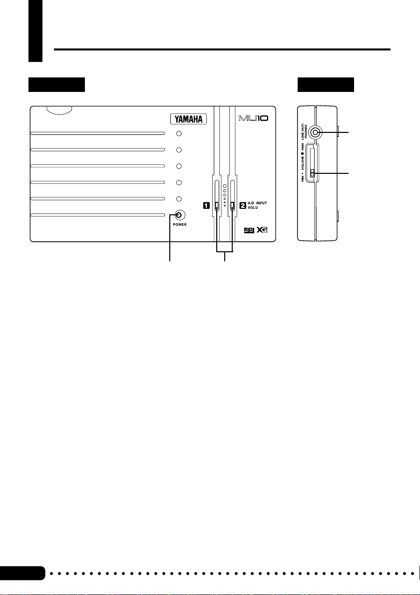
Panel Controls and Terminals
Top Panel Side Panel
TONE GENERATOR
e
r
A/D INPUT
VOLUME
POWER
qw
q POWER lamp
Lights when power is turned on. Also, flashes to indicate reception of MIDI Note On
messages and System Exclusive data. Also, flashes slowly when battery power becomes too low for proper operation.
GENERAL
w A/D INPUT VOLUME controls (1, 2)
For control of the A/D INPUT audio level.
e LINE OUT/PHONES jack
For connection to a set of stereo headphones, or an external amplifier/speaker system
(stereo mini plug). (See page 17.)
r VOLUME control
Adjusts the overall volume of the MU10.
○○○○○○○○○○○○○○○○○○○○○○○○○○○○○○○○○○○○○○○○○○○○○○
8
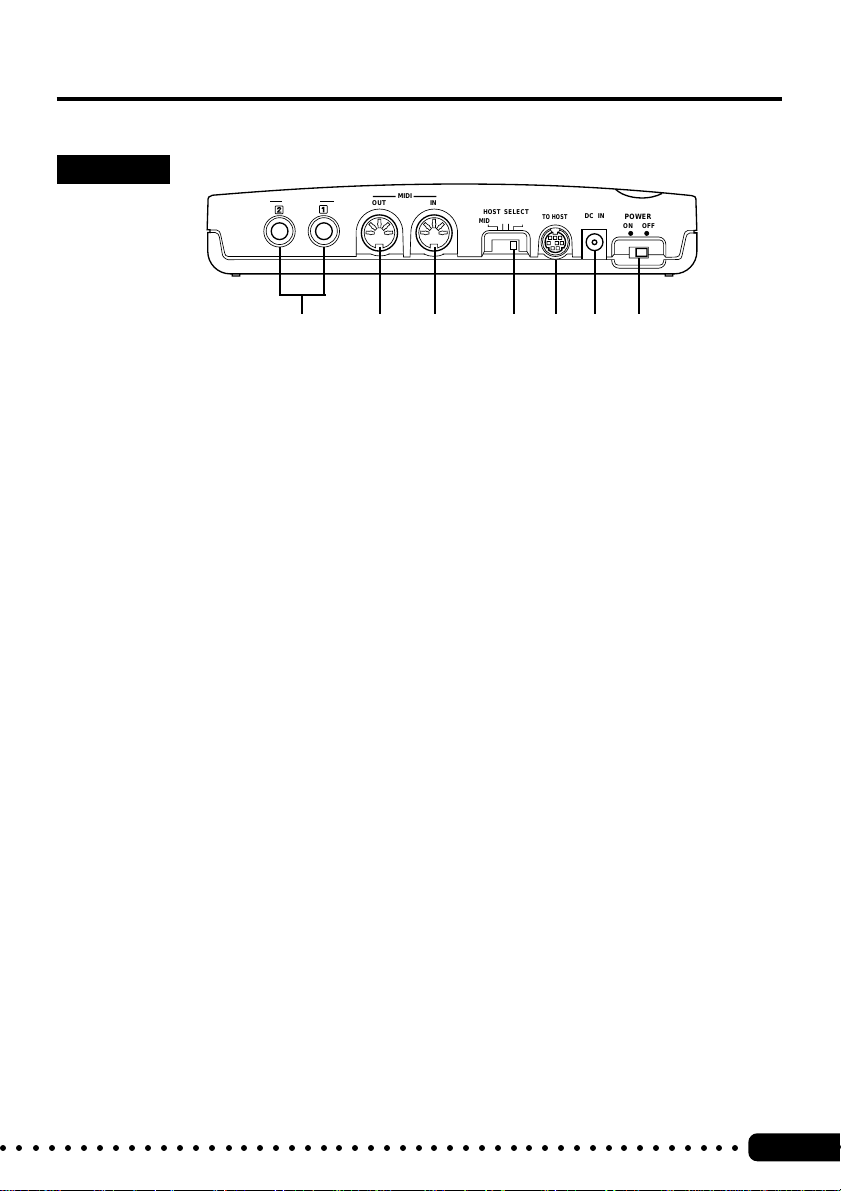
Panel Controls and Terminals
Rear Panel
A/D INPUT
tyuio!0!1
t A/D INPUT jacks (1, 2)
For connection of external audio sources, such as microphone, guitar, or CD player
(mono 1/4” plug). When using only one input source, be sure to connect it to the A/D
INPUT 1 jack. (See page 18.)
y MIDI OUT terminal
For connection to other MIDI devices, such as a MIDI keyboard or tone generator.
Used to relay data received via the TO HOST terminal.
u MIDI IN terminal
For connection to other MIDI devices, such as a MIDI keyboard, sequencer, or to a
computer via MIDI interface. When the HOST SELECT switch is set to MIDI, the
received data is sent to the internal tone generator. When the HOST SELECT switch is
set to PC-1, PC-2, or Mac, the received data is directly sent to the TO HOST terminal,
bypassing the internal tone generator. (See page 14 – 16.)
MIDI
OUT IN
HOST SELECT
MIDI Mac
PC-2 PC-1
TO HOST
DC IN
POWER
ON OFF
i HOST SELECT switch
For selecting the type of host computer, or (when set to MIDI) normal MIDI operation.
Available settings are: MIDI, PC-2 (IBM PC/AT and compatible computers), PC-1
(NEC PC 98 computers; for use in Japan), and Mac (Macintosh). (See page 15 – 16.)
o TO HOST terminal
For connection to a host compter. Use an appropriate serial interface cable according
to the type of host computer. (See page 15.)
!0 DC IN jack
For connection to a PA-3B, PA-1207 or equivalent AC power adaptor.
!1 POWER switch
For turning the power on and off. Turning the power on automatically sets the MU10
to the XG mode and initializes all settings and parameter values.
○○○○○○○○○○○○○○○○○○○○○○○○○○○○○○○○○○○○○○○○○○○○○○○
9

The MU10 — What It Is and What It Can Do
What It Is
The MU10 is a compact, highly portable MIDI tone generator, designed
especially for use with computers and MIDI music systems. Specifically, it
is a high-quality XG- and GM-compatible tone generator, with 676 Voices
and 21 drum Voices (percussion sets). The tone generator can be played
either from an external MIDI device (such as a keyboard or a sequencer) or a
computer. The MU10 also includes three independent digital effect sections
— with 11 types of Reverb, 11 types of Chorus, and 43 different Variation
effects — for enhancing the sound of the Voices.
The MU10 features a built-in host computer interface, allowing you to
directly connect it to your Macintosh or IBM PC/AT (and compatible)
computer—eliminating the need of installing a special MIDI interface to your
computer. With the proper sequencing software on the computer, the MU10
can be used for both recording and playing back of sequencer data. The
internal tone generator also allows for comprehensive control over all Voice
and effect parameters — via incoming system exclusive messages, transmitted from a sequencer or other MIDI device. (Refer to the MIDI Data Format
section on page 25 for details on controlling various MU10 parameters.)
The MU10 also features two convenient A/D INPUT jacks, allowing you to
connect external audio sources and mix those sources with the Voices.
Moreover, the built-in effects can be applied to the external sources as well
as the internal AWM2 Voices.
The MU10 is also the latest instrument in the Yamaha line to support the XG
format, a new addition to the General MIDI standard. In short, XG provides
for more instrument sounds and variations, and greater expressive control
over voices and effects.
○○○○○○○○○○○○○○○○○○○○○○○○○○○○○○○○○○○○○○○○○○○○○○
10

What It Can Do
Here are a few application ideas on how you can use the MU10. The list
below is not comprehensive, but is meant to be a general guide to the
possibilities and provide a starting point or springboard for your own creative
ideas and explorations.
■ Using in a MIDI Music System
Connect the MU10 to a computer with MIDI sequencing software, and
you’ve got comprehensive music making power—for recording, composing,
arranging, practicing, and editing. Combine it with a laptop computer, and
you’ve got a complete and portable music production system that’s ready to
go wherever you go. The built-in A/D Inputs let you connect an external
audio source (such as a microphone or guitar), allowing you to play along
with the MIDI tracks.
The MU10 is an ideal addition to larger MIDI studios as well, since it gives
you a high-quality 16-Part multi-timbral tone generator.
The MU10 — What It Is and What It Can Do
■ Multimedia
Since it’s portable and compatible with the XG and General MIDI formats,
the MU10 is a natural for multimedia applications. Because of its portability
and great sound, it’s the only tone generator you’ll need for recording,
editing and playing back MIDI data on your multimedia creations.
■ Using With a MIDI Keyboard in Live Performance
Simply connect the MU10 to a MIDI keyboard and play the dynamic Voices
in live performance situations. With the built-in A/D Inputs, you can even
use the MU10 as a simple 2-channel mixer. Bring a computer or MIDI data
player to your gig, and you can even mix another instrument (such as guitar
or bass) with the MIDI-driven Voices of the MU10.
○○○○○○○○○○○○○○○○○○○○○○○○○○○○○○○○○○○○○○○○○○○○○○○
11

Setting Up Your MU10
Setting Up the MU10 in Your Music System
Whatever your system, you should follow the basic instructions in this section when
setting up your MU10. Use the example illustrations as a general guide when making
the connections with your own system.
Power Supply
Your MU10 will run either from an optional AC adaptor or batteries. Whenever possible, you should use the AC adaptor, since the MU10 runs only for
a short time on battery power (approximately two hours and twenty minutes
on alkaline batteries).
■
NOTE
●
Before making any connections, make
sure that all equipment to be connected is turned off.
■ Using a Power Adaptor
Connect one end of the power adaptor
(optional Yamaha PA-3B, PA-1207, or
MIDI
OUT IN
HOST SELECT
MIDI Mac
PC-2 PC-1
TO HOST
DC IN
DC IN
POWER
ON OFF
equivalent) to the DC IN jack on the
rear panel, and the other end to a
suitable electrical outlet.
■
CAUTION
●
Do not attempt to use an AC adaptor
other than the PA-3B, PA-1207, or
equivalent. The use of an incompatible
adaptor may result in irreparable
damage to the MU10, and even pose a
serious shock hazard. (The recommended power adaptor may vary,
depending on your location. Please
consult your nearest Yamaha dealer for
details.)
●
Be sure to disconnect the power adaptor
from the outlet when the MU10 is not in
use for an extended period of time or
during electrical storms.
○○○○○○○○○○○○○○○○○○○○○○○○○○○○○○○○○○○○○○○○○○○○○○
12
Power
Adaptor

Setting Up Your MU10
■ Using Batteries
To use the MU10 on battery power,
remove the battery compartment cover
(as shown at the right) and insert six
1.5V AA size (SUM-3, R-6 or equivalent) manganese or alkaline batteries
in the battery compartment. Make
sure to follow the polarity indications
on the bottom case.
Securely replace the battery compartment cover when finished installing
the batteries.
■ When to Replace the Batteries
When the battery power runs too low to properly operate the MU10, the
POWER lamp will flash slowly. When this happens, replace all batteries
with a complete set of six new batteries of the same type.
■
CAUTION
●
NEVER mix old and new batteries or different types of batteries! Also, to
prevent possible damage due to battery leakage, remove the batteries from the
instrument if it is not to be used for an extended period of time.
●
The MU10 has no memory backup function. Turning the power off will auto-
matically initialize all settings and parameter values.
○○○○○○○○○○○○○○○○○○○○○○○○○○○○○○○○○○○○○○○○○○○○○○○
13

Setting Up Your MU10
Connections
In this section you’ll learn how to set up your MU10 with a computer or with
another MIDI device. You’ll also learn how to connect the MU10 with audio
equipment.
■
CAUTION
●
Turn off all devices before making connections.
Connecting With a Computer
You can connect the MU10 with your computer in one of two ways: 1) direct
(computer port — TO HOST terminal), or 2) via MIDI interface.
■ Direct Connection
Whatever computer you use, the connections are basically the same. However, the cable you use and the HOST SELECT switch setting differ according to the computer type. Other settings on the connected computer may be
required as well. (Refer to the owner’s manuals of your particular computer
and music software for more information.)
MIDI Thru
(Echo back)
ON
○○○○○○○○○○○○○○○○○○○○○○○○○○○○○○○○○○○○○○○○○○○○○○
14
Computer
(Sequencer software)
Serial port
TO HOST
MIDI OUT
MIDI Keyboard
MU10
Tone generator
MIDI OUTMIDI IN
MIDI IN
External tone
generator
Since data received
via the TO HOST
terminal is relayed
to the MIDI OUT
terminal, you can
connect an external
tone generator to
the MIDI OUT
terminal like this.

Setting Up Your MU10
● Macintosh
Connect the TO HOST terminal
of the MU10 to the Modem (or
Printer) port of the computer
with an optional Apple Macintosh peripheral cable (M0197),
then set the HOST SELECT
switch to Mac. Also, set the
MIDI interface clock to 1 MHz.
● PC98
Connect the TO HOST terminal
of the MU10 to the serial port of
the PC98 computer with an
optional 8-pin MINI DIN to 25pin D-SUB cable, then set the
HOST SELECT switch to PC-1.
Mac
mini DIN 8-pin mini DIN 8-pin
PC-1
mini DIN 8-pin
D-SUB 25-pin
● IBM PC/AT and Compatibles
Connect the TO HOST terminal
PC-2
of the MU10 to the serial port of
the IBM PC/AT (or compatible)
computer with an optional 8-pin
mini DIN 8-pin
MINI DIN to 9-pin D-SUB
cable, then set the HOST
SELECT switch to PC-2.
If you use an 8-pin MINI DIN
to 25-pin D-SUB cable, connect
mini DIN 8-pin
D-SUB 25-pin
D-SUB 9-pin
a 25-pin to 9-pin plug adaptor to
the D-SUB end of the cable.
○○○○○○○○○○○○○○○○○○○○○○○○○○○○○○○○○○○○○○○○○○○○○○○
D-SUB 9-pin
15

MIDI
Setting Up Your MU10
■ Connecting to a Computer With a MIDI Interface
Connect the MIDI IN terminal of the
MU10 with the MIDI OUT terminal
on the MIDI interface as shown at the
right, then set the HOST SELECT
switch to MIDI.
■
NOTE
●
If you are using a Macintosh computer,
you may need to set the MIDI interface
clock to an appropriate value. (Refer to
the owner’s manual of your particular
music software.)
●
When the HOST SELECT switch is set to
MIDI, data received via the TO HOST
terminal is ignored.
MIDI Thru
(Echo back)
HOST SELECT
Tone generator
MU10
MIDI Keyboard
ON
Computer
(Sequencer
software)
Serial
port
MIDI
OUT
MIDI
IN
MIDI
Interface
MIDI
IN
MIDI
OUT
Connecting With a MIDI Device
The MU10 can be integrated into any
MIDI system in a variety of ways. In
the example connection shown at the
right, the MU10 is being played from a
MIDI keyboard. Connect the MIDI IN
PITCH
SHIFT
OCTAVE
OCTAVE SHIFT
OCTAVE
RESET
terminal of the MU10 with the MIDI
OUT terminal on the MIDI keyboard,
set the HOST SELECT switch to
MIDI, and set the MIDI transmit
channel on the keyboard to the desired
value. (Refer to the owner’s manual of
that device for details.)
■
NOTE
●
MIDI channel 10 on the MU10 is
automatically set to play the drum
Voices.
○○○○○○○○○○○○○○○○○○○○○○○○○○○○○○○○○○○○○○○○○○○○○○
16
CONTROLLER NUMBER LIST
CONTROL CHANGE
1 MODULATION DEPTH
5 PORTAMENTO TIME
6 DATA ENTRY
7 MAIN VOLUME
8 BALANCE CONTROL
10 PANPOT
11 EXPRESSION
ASSIGNABLE
PROGRAM RESET SYSTEM WHEEL ASSIGNSEQUENCER
BANK
STOP CONTINUESTART
TEMPO
SELECT
MIDI OUT
PROGRAM
CHANGE
MIDI Keyboard
64 HOLD1(DAMPER)
74 BRIGHTNESS
(RPN)
65 PORTAMENTO
84 PORTAMENTO CONTROL
120 PITCH BEND SENSITIVITY
66 SOSTENUTO(CHORD HOLD)
91 REVERB DEPTH
121 FINE TUNING
67 SOFT PEDAL
92 TREMOLO DEPTH
122 COARSE TUNING
(NRPN)
69 HOLD2
93 CHORUS DEPTH
71 HARMONIC CONTENT
94 VARIATION DEPTH
123 VIBRATO RATE
72 RELEASE TIME
95 PHASER DEPTH
124 VIBRATO DEPTH
73 ATTACK TIME
125 VIBRATO DELAY
TRANSPOSE
MIDI
GM
XG
FIXED
SOUND
MERGE
DRUM
CONTROLLER
NRPN
RPN
CH
ON
ON
VELOCITY
OFF
ON/OFF
NUMBER
MIDI IN
Tone generator
MU10
DC IN
IN MIDI OUT
POWER ON OFF
134 DRUM EG DECAY TIME
135 DRUM PITCH COARSE
136 DRUM PITCH FINE
137 DRUM LEVEL
138 DRUM PAN
139 DRUM REVERB DEPTH
140 DRUM CHORUS DEPTH
141 DRUM VARIATION DEPTH
142 CHANNEL PRESSURE
143 KEY PRESSURE
144 MASTER VOLUME
145 MASTER BALANCE
146 MASTER TUNING
147 VELOCITY
148 TEMPO
OTHERS
126 FILTER CUTOFF FREQUENCY
127 FILTER RESONANCE
128 EG ATTACK TIME
129 EG DECAY TIME
130 EG RELEASE TIME
131 DRUM FILTER CUTOFF FREQUENCY
132 DRUM FILTER RESONANCE
133 DRUM EG ATTACK TIME
1 2 3 4 5 6 7 8 9 A B C D E F 0
HOST SELECT
MIDI
MIDI KEYBOARD CBX-K1
ENTER
HEXA
DECIMAL
DECIMAL

Setting Up Your MU10
MIN MAXVOLUME LINE OUT/
PHONES
TONE VOLUME
LOW HIGH
POWER
ON/
OFF
TONE VOLUME
LOW HIGH
POWER
ON/
OFF
Connecting to Audio Equipment
In order to hear the sounds of the MU10, you must connect it to a set of
stereo headphones or an amplifier/speaker system. Connect the headphones
or audio cable to the stereo mini jack on the side panel. The particular cable
that you use depends on your audio equipment. (In most cases this would be
a stereo mini/dual RCA-pin cable or a stereo mini/stereo mini cable.)
MIN MAXVOLUME LINE OUT/
PHONES
Stereo
Stereo mini
mini
INPUT
INPUT
Audio equipment
■
CAUTION
●
After making connections, turn down the volume controls on all devices,
then turn on the power of each device in the following order:
1) External MIDI device or computer
2) MU10
3) Audio equipment
When turning off the power, simply reverse the order. This is done to
avoid damaging any of the equipment and connected speakers (as well as
your ears!).
○○○○○○○○○○○○○○○○○○○○○○○○○○○○○○○○○○○○○○○○○○○○○○○
17

Using the A/D INPUT Function
The MU10 also features an A/D INPUT function that allows you to connect two
external audio sources — such as a microphone, guitar, or CD player — and mix those
sources with the Voices of the MU10. For example, you could use this to sing or play
a guitar or keyboard over backing tracks played with the MU10 Voices from a MIDI
sequencer. With a MIDI keyboard connected to the MU10, you could plug in a CD
player and play keyboard parts along with your favorite CDs.
The built-in effects of the MU10 are also applied to the INPUT sources.
■
NOTE
●
When the A/D INPUT 1 jack (or both 1 and 2) is connected, the A/D INPUT
function is turned on and the maximum polyphony (simultaneous notes) of the
MU10 is reduced from 32 to 30.
●
Audio signals received via the A/D INPUT 1 and 2 jacks are mixed to one part,
then processed through the effect sections and mixed with the internal Voices of
the MU10.
●
When the power is turned on, the A/D Input parameters are reset to the follow-
ing values:
Input Gain — Mic
Bank Select — 0
Receive Channel — OFF
Volume — 100
Chorus Send — 0
Reverb Send — 40
Receive Program Change — OFF
Receive Bank Select — OFF
●
When the A/D Input is active (i.e., when the A/D INPUT 1 jack is connected),
Variation Send is set to 0. All other parameter settings are maintained.
○○○○○○○○○○○○○○○○○○○○○○○○○○○○○○○○○○○○○○○○○○○○○○
18

Using the A/D INPUT Function
MIN MAXVOLUME
A/D INPUT
VOLUME
● Operation
1 Turn down all volume controls.
This includes the A/D INPUT
VOLUME sliders on the top panel,
and the VOLUME slider on the
side panel, as well as volume
controls on any connected equipment.
Front Panel
Side Panel
2 Connect the cable(s) from the external source(s) to the A/D INPUT
jack(s).
When using a single mono source, connect it to the A/D INPUT 1 jack, so
that the A/D INPUT function is on. (Connecting the source to only the A/
D INPUT 2 jack does not turn on the A/D INPUT function.)
3 Turn up the various volume controls until the level is appropriate.
Start with the controls on any connected equipment, then the VOLUME
slider on the side panel, and finally slowly turn up the A/D INPUT
VOLUME slider while playing the external instrument or sound source.
○○○○○○○○○○○○○○○○○○○○○○○○○○○○○○○○○○○○○○○○○○○○○○○
19

Using the A/D INPUT Function
■ Changing the Input Gain Setting
When the power is turned on, the A/D INPUTs are automatically set to
receive mic level signals, such as a microphone or electric guitar. To use a
keyboard or a CD player, you will need to change the setting from “mic” to
“line.” This is done by sending the MU10 a specific MIDI System Exclusive
message (usually from a sequencer).
● Operation
1 Connect a MIDI sequencer (or other MIDI device) to the TO HOST
terminal or MIDI IN terminal. (See page 14 – 16.)
The device must be able to transmit System Exclusive messages. (Refer
to the owner’s manual of the particular device or software for detailed
instructions.)
2 Send the appropriate message from the sequencer.
To set the A/D INPUTs to “line,” send this message : F0 43 1n 4c 10 00 00 01 F7
To set the A/D INPUTs to “mic,” send this message : F0 43 1n 4c 10 00 00 00 F7
(n = device number)
For more details, refer to the MIDI Data Format section on page 25.
Continue with steps 1 - 3 in the previous instructions to use the A/D
INPUTs with the new setting.
○○○○○○○○○○○○○○○○○○○○○○○○○○○○○○○○○○○○○○○○○○○○○○
20

MU10 Overview and Features
This section covers the performance modes of the
MU10 and describes in detail Voice- and Effectrelated controls and features.
The MU10 has 32-note polyphony and is 16-Part
multitimbral, which means it can play up to 16
different instrument Parts (one Part per each of the
16 MIDI channels), each Part having its own
Voice. Up to 16 different Voices can be sounded
simultaneously.
The MU10 features both XG and TG300B
performance modes. Normally the MU10 plays in
XG mode. However, since it automatically
recognizes which mode to select based on
incoming MIDI data, you can easily change the
mode by MIDI System Exclusive messages that
you program in sequencer data, at the head of your
composition.
Please note the following:
• Turning on the power of the MU10 will
automatically initialize all MU10 settings,
or parameter values.
• Since the MU10 requires about half a
second to change modes when it receives a
mode change message, be sure to insert at
least one blank measure at the top in order
to allow enough time for the mode to
change before your actual music data
begins.
● XG Mode
In XG mode the MU10 will play XG-compatible
multitimbral data, as well as multitimbral data
created for the GM System Level 1 format.
In XG mode the MU10 can:
• Play up to 16 Parts.
• Choose from 480 Normal Voices and 11
Drum Voices.
● TG300B Mode
In TG300B mode the MU10 will play multitimbral
music data created for TG300B-compatible tone
generators. TG300B mode also provides compatibility with the GM System Level 1 format.
In TG300B mode the MU10 can:
• Play up to 16 Parts.
• Choose from 579 Normal Voices and 10
Drum Voices.
■ Voices and Elements
An MU10 Voice can be made up of one or two
elements (i.e., sounds), depending on the complexity of the Voice. Many Voices are made up of only
one element. Two-element Voices are made up of
two one-element Voices, and may be configured in
a variety of ways.
The number of elements in use determines the
maximum number of simultaneous notes (polyphony) which the MU10 can play at any given
time, depending on the amount of incoming MIDI
Note data. For details about the number of
elements used in each Voice, see the XG/TG300B
Normal Voice List on page 42.
■ Normal Voices and Drum Voices
The MU10 has two types of Voices—Normal
Voices and Drum Voices. (In this Owner’s Manual,
in general the word Voice refers to a Normal
Voice.)
The distinction between a Normal Voice and a
Drum Voice is as follows:
• A Normal Voice is simply a pitched Voice
which can be played on a musical scale from
low to high, such as a piano or trumpet. The
MU10 has 676 Normal Voices.
• A Drum Voice is a complete set of drum and
other percussion sounds, each sound having a
fixed pitch. Each sound is assigned to a specific
MIDI Note number (which also corresponds to
a key on a MIDI keyboard). The MU10 has 21
Drum Voices.
○○○○○○○○○○○○○○○○○○○○○○○○○○○○○○○○○○○○○○○○○○○○○○○
21

MU10 Overview and Features
■ Maximum Polyphony
The MU10 can play a maximum of 32 notes
polyphony at once. (When the A/D INPUT 1 jack
or both the 1 and 2 jacks are connected, the A/D
INPUT function is turned on and the maximum
polyphony is reduced to 30.) However, the actual
number of notes that will play at any given time is
determined by the number of elements in use
across the 16 Parts.
For example, if you use only one-element Voices,
you can achieve the full 32 notes maximum
polyphony. If you use one or more two-element
Voices, however, maximum polyphony will be
reduced accordingly.
The MU10 is a last-note-priority tone generator,
which means that if it receives more than 32 notes
of MIDI Note data at any time, earlier (first) notes
will automatically cut off to accommodate the
most recent (last) incoming notes.
■ Part Priority
Each of the MU10’s 16 Parts corresponds to each
of the 16 MIDI channels (1 – 16). If incoming
Note data exceeds the maximum polyphony, the
MU10 will prioritize which Parts are played first,
in the following order, from higher priority to
lower:
• Channel 10 (Drum Part), 1, 2, 3, 4, 5, 6, 7, 8, 9, 11,
12, 13, 14,15, 16.
Therefore, if you are creating your own music data
using sequencer software, you should assign your
most important Parts (such as melody and bass) to
higher priority MIDI channels (i.e., lower MIDI
channel numbers) in order to preserve the integrity
of your composition. Note that with the GM
System Level 1, the Drum Part is always assigned
to MIDI channel 10.
○○○○○○○○○○○○○○○○○○○○○○○○○○○○○○○○○○○○○○○○○○○○○○
22
■ Element Reserve
The MU10 has an Element Reserve feature that
lets you reserve a specified number of notes for
certain Parts, in order to keep notes from being
“stolen” from those Parts by other Parts if
incoming MIDI Note data exceeds maximum
available polyphony.
For example, if you specify an Element Reserve
value of “10” for Part 1, then Part 1 will always
keep 10 elements for itself. You can set Element
Reserve values with MIDI System Exclusive
messages (see XG Native Parameter Change on
page 30, and <Table 1 - 4> on page 35).
■ Selecting Voices
The MU10 not only contains the 128 basic GM
Voices and GM drum set, but many variation
Voices as well—to give you access to a total of
676 Normal Voices and 21 Drum Voices.
In XG mode, the basic 128 GM Voices can be
accessed by selecting Program numbers 1 – 128.
Other Voices can be accessed by selecting both
bank numbers and Program Change numbers. The
Voice bank can be selected via MIDI Control
Change Bank Select (MSB and LSB) messages. In
XG mode, the MSB value determines the Voice
type (Normal, Drum), while the LSB value actually
selects the bank (excluding the SFX bank).
When the MU10 is in TG300B mode, the Voice
banks can be selected with appropriate MSB
numbers, as LSB is fixed.
Lists of all available Voices along with bank and
program numbers are provided on pages 42 – 49.
Note that the 128 MIDI Program Change numbers
consist of 0 through 127, whereas the 128 MU10
program numbers consist of 1 through 128.
Depending on the sequencing hardware and
software you use, you may have to convert the
MU10 program numbers to the appropriate
Program Change numbers.
* For more information about Bank Select and
Program Change messages, see About MIDI,
page 24.

■ Effect Types
The MU10 features dozens of extremely versatile
digital effects generated by Yamaha’s advanced
Digital Signal Processing (DSP) technology—
which add a completely new dimension to your
MU10’s sound.
There are three distinct effect types, or effect
sections, each of which include a variety of
individual effects. There are 11 Reverb type
effects, 11 Chorus type effects, and 43 Variation
type effects. For a complete list of effects, see the
Effect Type List on page 50.
These effects are configured, or routed, in one of
two ways—to be either a System Effect or an
Insertion Effect. The difference is as follows:
• SYSTEM EFFECT
- Applies the designated effect to all 16 Parts.
• INSERTION EFFECT
- Applies the designated effect to only one specific
Part.
Reverb and Chorus effect types are dedicated
System Effects, and therefore are applied to the
overall “mix”. The Variation effect type, however,
can be configured as either a System Effect or an
Insertion Effect. To designate effect types and
parameter values via MIDI messages, see XG
Native Parameter Change, page 30.
* Effects can be applied to A/D Input Sources as
well as the internal voices of the MU10.
MU10 Overview and Features
■ 16 bit A/D Input x 2
The MU10 features A/D INPUT 1, 2 jacks for
connection of external audio sources such as a
microphone, guitar, bass, or CD player.
Audio signals received via A/D INPUT 1 and 2
jacks are mixed to one part, then processed
through the effect sections and mixed with the
internal voices of the MU10. (See “Using the A/D
INPUT Function” on page 18)
○○○○○○○○○○○○○○○○○○○○○○○○○○○○○○○○○○○○○○○○○○○○○○○
23

About MIDI
■ What is MIDI?
MIDI is an acronym that stands for Musical
Instrument Digital Interface, which allows
electronic musical instruments to “communicate”
with each other, by sending and receiving
compatible Note, Control Change, Program
Change and various other types of MIDI data, or
messages.
■ MIDI Messages Received by the
MU10
The MU10 is controlled by various types of
incoming MIDI messages which automatically
determine play mode, select MIDI channels,
Voices and effects, change parameter values, and
of course play the Voices specified for the various
Parts—complete with all the subtle nuances and
powerful dynamics of expression that the
composer originally intended. Below is an
explanation of the various types of MIDI messages
which the MU10 can receive.
● Key On/Key Off
Key On/Key Off messages, also called Note
messages, tell the MU10 which notes to play, the
Velocity value (depending on how hard the keys
are struck) at which to play them, and how long to
play them—i.e., when to start (On) and stop (Off)
playing each note.
● Program Change
Program Change messages tell the MU10 which
Voice to select for each Part. You can insert
Program Change messages at any desired location
in a song. Combining Bank Select numbers let you
select various Voices from the hundreds of Voices
available in the MU10.
● Pitch Bend
Pitch Bend messages are continuous controller
messages that allow the pitch of designated notes
to be raised or lowered by a specified amount over
a specified duration.
● Channel Aftertouch
Channel Aftertouch is a pressure sensing function
which lets you control various functions by how
hard you press the keys, over the entire channel.
● Polyphonic Aftertouch
Polyphonic Aftertouch is a pressure sensing
function which lets you control various functions
by how hard you press the keys, for each
individual key.
● System Exclusive
System Exclusive messages control various
functions of the MU10, including master volume
and master tuning, play mode (XG or TG300B),
effect type and various other parameters specifically related to the MU10.
● Control Change
Control Change messages let you select a Voice
bank, control volume, panning, modulation,
portamento time, brightness and various other
controller parameters, through specific Control
Change numbers which correspond to each of the
various parameters.
○○○○○○○○○○○○○○○○○○○○○○○○○○○○○○○○○○○○○○○○○○○○○○
24

MIDI Data Format
By sending various types of MIDI messages you can
directly control and change the settings on the MU10.
Please refer to the owner’s manual of your software
and hardware for information about how to transmit
MIDI messages to the MU10.
If the Drum Setup parameter Rcv NOTE OFF (Table
1-6) = OFF, the Drum Part will ignore Key Off
messages.
If the Drum Setup parameter Rcv NOTE ON = OFF
(Table 1-6), the Drum Part will ignore Key On
messages.
■ RECEPTION
1. CHANNEL MESSAGES
1.1 Key On / Key Off
Messages which are generated when the keyboard is
played.
Reception note range = C-2 (0)-G8 (127), C3 = 60
Velocity range = 1-127 (Only the Key On velocity is
received)
Key On: Generated when a key is pressed.
Key Off: Generated when a key is released.
Each message includes a specific note number which
corresponds to the key which is pressed, plus a
velocity value based on how hard the key is struck.
If the Multi Part parameter Rcv NOTE MESSAGE
(Table 1-4) = OFF for a specific Part, that Part will
1.2 Control Change
Messages which control volume, panning, and other
controller parameters.
Each type of Control Change message is assigned to a
specific control number.
If the Multi Part parameter for each Control Change
Receive (Table 1-4, nn30-nn40) = OFF, that Part will
ignore the specific Control Change message.
1.2.1 Bank Select
Messages which select variation Voice bank numbers.
CNTRL# PARAMETER DATA RANGE
0 Bank Select MSB 0:Normal, 63:User Voices,
32 Bank Select LSB 0...127
64:SFX, 126:SFX Kit,
127:Drum
ignore Key On and Key Off messages.
Decimal - Hexadecimal Conversion Chart
Many MIDI messages listed in the MIDI Data Format section, are expressed in hexadecimal numbers. The
chart below lists the corresponding decimal number for each hexadecimal number. (Hexadecimal numbers
may include the letter “H” as a suffix.)
Dec Hex Dec Hex Dec Hex Dec Hex Dec Hex Dec Hex Dec Hex Dec Hex
0
1
2
3
4
5
6
7
8
9
10
11
12
13
14
15
○○○○○○○○○○○○○○○○○○○○○○○○○○○○○○○○○○○○○○○○○○○○○○○
16
00
17
01
18
02
03
19
20
04
21
05
06
22
23
07
24
08
09
25
26
0A
27
0B
0C
28
0D
0E
30311E
0F
32
10
11
12
13
14
15
16
17
18
19
1A
1B
1C
1D29
1F
20
48
21
33
34
35
36
37
38
39
40
41
42
43
44
45
46
47
49
22
50
51
23
24
52
25
53
26
54
27
55
56
28
57
29
58
2A
59
2B
2C
60
2D
61
62
2E
63
2F
64
30
65
31
66
32
33
67
68
34
35
69
70
36
71
37
72
38
73
39
3A
74
3B
75
76
3C
77
3D
78
3E
79
3F
80
40
81
41
82
42
83
43
84
44
85
45
86
46
87
47
48
88
49
89
4A
90
4B
91
92
4C
93
4D
4E
94
95
4F
96
50
51
97
98
52
53
99
100
54
101
55
56
102
57
103
58
104
59
105
5A
106
107
5B
108
5C
109
5D
110
5E
111
5F
112
60
113
61
114
62
115
63
116
64
65
117
66
118
67
119
68
120
121
69
122
6A
123
6B
124
6C
125
6D
6E
126
6F
127
70
71
72
73
74
75
76
77
78
79
7A
7B
7C
7D
7E
7F
25

MIDI Data Format
You can select the Voice banks with MSB and LSB
numbers. MSB and LSB functions differently
depending on the play mode.
In XG mode, MSB numbers select Voice type
(Normal Voice or Drum Voice), and LSB numbers
select Voice banks. In TG300B mode, LSB is fixed,
and MSB numbers select Voice banks.(See Voice Lists
on page 42 – 49)
A new bank selection will not become effective until
the next Program Change message is received.
1.2.2 Modulation
Messages which control vibrato depth.
CNTRL# PARAMETER DATA RANGE
1 Modulation 0...127
A setting of 0 = vibrato off, and a setting of 127 =
maximum vibrato.
1.2.3 Portamento Time
Messages which control the duration of portamento,
or a continuous pitch glide between successively
played notes.
CNTRL# PARAMETER DATA RANGE
5 Portamento Time 0...127
When the parameter 1.2.9 Portamento = ON, values
will adjust the speed of pitch change.
A setting of 0 = minimum portamento time, and 127
= maximum portamento time.
1.2.7 Expression
Messages which control intonation expression of each Part.
CNTRL# PARAMETER DATA RANGE
11 Expression 0...127
A setting of 0 = minimum expression volume, and
127 = maximum expression volume.
1.2.8 Hold1
Messages which control sustain on/off.
CNTRL# PARAMETER DATA RANGE
64 Hold1 0...127
Settings between 0-63 = sustain off, and settings
between 64-127 = sustain on.
1.2.9 Portamento
Messages which control portamento on/off.
CNTRL# PARAMETER DATA RANGE
65 Portamento 0...127
Settings between 0-63 = portamento off, and settings
between 64-127 = portamento on.
The parameter 1.2.3 Portamento Time controls the
portamento speed.
1.2.10 Sostenuto
Messages which control sostenuto on/off.
CNTRL# PARAMETER DATA RANGE
66 Sostenuto 0...127
Holding specific notes and then pressing and holding
1.2.4 Data Entry
Messages which set the value for the parameter
specified by RPN/NRPN.
CNTRL# PARAMETER DATA RANGE
6 Data Entry MSB 0...127
38 Data Entry LSB 0...127
Parameter value is determined by combining MSB
and LSB.
1.2.5 Main Volume
Messages which control the volume of each Part.
CNTRL# PARAMETER DATA RANGE
7 Main Volume 0...127
A setting of 0 = minimum volume, and 127 =
maximum volume.
1.2.6 Pan
Messages which control the stereo panning position of
each Part.
CNTRL# PARAMETER DATA RANGE
10 Pan 0...127
A setting of 0 = extreme left position, and 127 =
extreme right position.
○○○○○○○○○○○○○○○○○○○○○○○○○○○○○○○○○○○○○○○○○○○○○○
26
the sostenuto pedal will sustain those notes as you
play subsequent notes, until the pedal is released.
Settings between 0-63 = sostenuto off, and settings
between 64-127 = sostenuto on.
1.2.11 Soft Pedal
Messages which control soft pedal on/off.
CNTRL# PARAMETER DATA RANGE
67 Soft Pedal 0...127
Notes played while holding the soft pedal will be
dampened. Settings between 0-63 = soft pedal off, and
settings between 64-127 = soft pedal on.
1.2.12 Harmonic Content
Messages which adjust the resonance set for each
Voice.
CNTRL# PARAMETER DATA RANGE
71 Harmonic Content 0...127 (0 : -64, 64 : +0,
127 : +63)
The value set here is an offset value which will be
added to or subtracted from the Voice data.
Higher values will result in a more resonant sound.
Depending on the Voice, the effective range may be
narrower than the range available for adjustment.

MIDI Data Format
1.2.13 Release Time
Messages which adjust the envelope release time set
for each Voice.
CNTRL# PARAMETER DATA RANGE
72 Release Time 0...127 (0 : -64, 64 : +0,
127 : +63)
The value set here is an offset value which will be
added to or subtracted from the Voice data.
1.2.14 Attack Time
Messages which adjust the envelope attack time set
for each Voice.
CNTRL# PARAMETER DATA RANGE
73 Attack Time 0...127 (0 : -64, 64 : +0,
127 : +63)
The value set here is an offset value which will be
added to or subtracted from the Voice data.
1.2.15 Brightness
Messages which adjust the filter cutoff frequency set
for each Voice.
CNTRL# PARAMETER DATA RANGE
74 Brightness 0...127 (0 : -64, 64 : +0,
127 : +63)
The value set here is an offset value which will be
added to or subtracted from the Voice data.
Lower values will result in a softer sound.
Depending on the Voice, the effective range may be
narrower than the range available for adjustment.
1.2.16 Portamento Control
Messages which apply a portamento between the
currently sounding note and the subsequent note.
CNTRL# PARAMETER DATA RANGE
84
Portamento Control
0...127
Portamento Control is transmitted specifying the Note
On Key of the currently-sounding note.
Specify a Portamento Source Key number between 0-
127.
When a Portamento Control message is received, the
currently sounding pitch will change with a
Portamento Time of 0 to the next Key On key on the
same channel.
For example, the following settings would apply a
portamento from note C3 to C4.
90 3C 7F ........... C3 = Key On
B0 54 3C........... Source Key number set to C3
90 48 7F ........... C4 = Key On (When C4 = on, C3
is raised by a portamento to C4.)
Even if the Multi Part parameter Rcv PORTAMENTO
(Table 1-4) = OFF, the Portamento Control message
will be received.
1.2.17 Effect1 Depth (Reverb Send Level)
Messages which adjust the send level for the Reverb
effect.
CNTRL# PARAMETER DATA RANGE
91 Effect1 Depth 0...127
1.2.18 Effect3 Depth (Chorus Send Level)
Messages which adjust the send level for the Chorus
effect.
CNTRL# PARAMETER DATA RANGE
93 Effect3 Depth 0...127
1.2.19 Effect4 Depth (Variation Effect Send Level)
Messages which adjust the send level for the Variation
effect.
CNTRL# PARAMETER DATA RANGE
94 Effect4 Depth 0...127
If Variation Connection (Table 1-3) = 1 (System), this
message sets the send level for the Variation effect.
If Variation Connection = 0 (Insertion), this has no
effect.
1.2.20 Data Increment / Decrement (for RPN)
Messages which increase or decrease the MSB value
of Pitch Bend Sensitivity, Fine Tune, or Coarse Tune
in steps of 1.
CNTRL# PARAMETER DATA RANGE
96 RPN Increment 0...127
97 RPN Decrement 0...127
The data byte is ignored.
When the maximum value or minimum value is
reached, the value will not be incremented or
decremented further.
(Incrementing the Fine Tune will not cause the Coarse
Tune to be incremented.)
1.2.21 NRPN (Non-Registered Parameter Number)
Messages which adjust a Voice’s vibrato, filter, EG,
drum setup or other parameter settings.
CNTRL# PARAMETER DATA RANGE
98 NRPN LSB 0...127
99 NRPN MSB 0...127
First send the NRPN MSB and NRPN LSB to specify
the parameter which is to be controlled. Then use
Data Entry to set the value of the specified parameter.
* Note that once the NRPN has been set for a channel,
subsequent data entry will be recognized as the same
NRPN’s value change. Therefore, after you use the
NRPN, you should set a Null (7FH, 7FH) value to
avoid an unexpected result.
○○○○○○○○○○○○○○○○○○○○○○○○○○○○○○○○○○○○○○○○○○○○○○○
27

MIDI Data Format
The following NRPN numbers can be received.
NRPN
MSB LSB MSB
01H 08H mmH Vibrato Rate
01H 09H mmH Vibrato Depth
01H 0AH mmH Vibrato Delay
01H 20H mmH Filter Cutoff Frequency
01H 21H mmH Filter Resonance
01H 63H mmH EG Attack Time
01H 64H mmH EG Decay Time
01H 66H mmH EG Release Time
14H rrH mmH Drum Filter Cutoff Frequency
15H rrH mmH Drum Filter Resonance
16H rrH mmH Drum EG Attack Rate
17H rrH mmH Drum EG Decay Rate
18H rrH mmH Drum Instrument Pitch Coarse
19H rrH mmH Drum Instrument Pitch Fine
1AH rrH mmH Drum Instrument Level
1CH rrH mmH Drum Instrument Pan
1DH rrH mmH
1EH rrH mmH
1FH rrH mmH
DATA ENTRY
PARAMETER NAME and VALUE RANGE
mm : 00H-40H-7FH (-64 - 0 - +63)
mm : 00H-40H-7FH (-64 - 0 - +63)
mm : 00H-40H-7FH (-64 - 0 - +63)
mm : 00H-40H-7FH (-64 - 0 - +63)
mm : 00H-40H-7FH (-64 - 0 - +63)
mm : 00H-40H-7FH (-64 - 0 - +63)
mm : 00H-40H-7FH (-64 - 0 - +63)
mm : 00H-40H-7FH (-64 - 0 - +63)
mm : 00H-40H-7FH (-64 - 0 - +63)
rr : drum instrument note number
mm : 00H-40H-7FH (-64 - 0 - +63)
rr : drum instrument note number
mm : 00H-40H-7FH (-64 - 0 - +63)
rr : drum instrument note number
mm : 00H-40H-7FH (-64 - 0 - +63)
rr : drum instrument note number
Applies to both Decay1 and 2.
mm : 00H-40H-7FH (-64 - 0 - +63)
rr : drum instrument note number
mm : 00H-40H-7FH (-64 - 0 - +63)
rr : drum instrument note number
mm : 00-7F (0-max)
rr : drum instrument note number
mm : 00H-40H-7FH
(random, left-center-right)
rr : drum instrument note number
Drum Instrument Reverb Send Level
mm : 00H-7FH (0-max)
rr : drum instrument note number
Drum Instrument Chorus Send Level
mm : 00H-7FH (0-max)
rr : drum instrument note number
Drum Instrument Variation Send Le vel
mm : 00H-7FH (0-max)
rr : drum instrument note number
MSB 14H-1FH (for Drum) is valid only if the Multi
Part parameter (Table 1-4) PART MODE = DRUMS 1
or DRUMS2 for that channel. (If PART MODE =
DRUM, no values will be changed.)
○○○○○○○○○○○○○○○○○○○○○○○○○○○○○○○○○○○○○○○○○○○○○○
28
1.2.22 RPN (Registered Parameter Number)
Messages which offset, or add or subtract values from
a Part’s pitch bend sensitivity, tuning, or other
parameter settings.
CNTRL# PARAMETER DATA RANGE
100 RPN LSB 0...127 (Default:7FH)
101 RPN MSB 0...127 (Default:7FH)
* Note that once the RPN has been set for a channel,
subsequent data entry will be recognized as the same
RPN’s value change. Therefore after you use the
RPN, you should set a Null (7FH, 7FH) value to
avoid an unexpected result.
The following RPN numbers can be received.
RPN DATA ENTRY
MSB LSB MSB LSB
00H 00H mmH -- Pitch Bend Sensitivity
00H 01H
00H 02H mmH -- Coarse Tuning
7FH 7FH -- -- RPN null
mmH 11H
PARAMETER NAME and VALUE RANGE
mm : 00-18H (0-24 chromatic steps)
Assignable in chromatic steps up to
2 octaves
Default : 02H
LSB value is ignored.
Fine Tuning
mm : 00H-40H-7FH (-64 - 0 - +63)
mm : 28H-40H-58H (-24 - +24 chromatic steps)
LSB value is ignored.
Cancels RPN and NRPN numbers.
1.2.23 Channel Mode Messages
The following Channel Mode Messages can be received.
2nd BYTE 3rd BYTE MESSAGE
120 0 All Sounds Off
121 0 Reset All Controllers
123 0 All Notes Off
124 0 Omni Off
125 0 Omni On
126 0 - 16 Mono
127 0 Poly
1.2.23.1 All Sounds Off
Terminates all sounds currently sounding on the
specified channel. However, the status of channel
messages such as Note On and Hold On is
maintained.
1.2.23.2 Reset All Controllers
The values of the following controllers will be
reset to the defaults.
CONTROLLER VALUE
Pitch Bend Change ±0 (center)
Channel Aftertouch 0 (off)
Polyphonic Aftertouch 0 (off)
Modulation 0 (off)
Expression 127 (max)

MIDI Data Format
Hold1 0 (off)
Portamento 0 (off)
Sostenuto 0 (off)
Soft Pedal 0 (off)
Portamento Control cancels the Portamento Source
RPN number not specified; internal
NRPN number not specified; internal
Key Number that was received.
data will not change.
data will not change.
1.2.23.3 All Notes Off
Terminates all notes currently on for the specified
channel. However, if Hold1 or Sostenuto is on,
If the Multi Part parameter Rcv CHANNEL AFTER
TOUCH (Table 1-4) = OFF, that Part will not receive
Channel Aftertouch.
1.6 Polyphonic Aftertouch
Messages which let you control various functions by
the pressure you apply to the keys after the initial
striking of the keys, for each individual key.
If the Multi Part parameter Rcv POLYPHONIC
AFTER TOUCH (Table 1-4) = OFF, that Part will not
receive Polyphonic Aftertouch. Effective range is
between note numbers 36-97.
notes will continue sounding until these are turned
off.
1.2.23.4 Omni Off
Performs the same function as when an All Notes
Off message is received.
1.2.23.5 Omni On
2. SYSTEM EXCLUSIVE MESSAGES
System Exclusive messages control various functions
of the MU10, including master volume and master
tuning, play mode, effect type and various other
parameters.
* The device number of the MU10 is fixed to “All”.
Performs the same function as when an All Notes
Off message is received.
1.2.23.6 Mono
Performs the same function as when an All Sounds
Off message is received, and if the 3rd byte (mono
number) is in the range of 0-16, sets the corresponding channel to Mono Mode (Mode 4 : m =
1).
1.2.23.7 Poly
Performs the same function as when an All Sounds
Off message is received, and sets the corresponding
channel to Poly Mode (Mode 3).
1.3 Program Change
Messages for Voice selection.
With a combination of Bank Select, you can select not
only basic Voice numbers, but also variation Voice
bank numbers.
If the Multi Part parameter Rcv PROGRAM
CHANGE (Table 1-4) = OFF, that Part will not
receive Program Change messages.
1.4 Pitch Bend
Messages for pitch bend wheel values.
If the Multi Part parameter Rcv PITCH BEND
CHANGE (Table 1-4) = OFF, that Part will not
receive Pitch Bend messages.
1.5 Channel Aftertouch
Messages which let you control various functions by
the pressure you apply to the keys after the initial
striking of the keys, over the entire channel.
○○○○○○○○○○○○○○○○○○○○○○○○○○○○○○○○○○○○○○○○○○○○○○○
2.1 Parameter Change
The MU10 receives the following parameter change
messages.
[ UNIVERSAL REALTIME MESSAGE ]
1) Master Volume
[ UNIVERSAL NON REALTIME MESSAGE ]
1) General MIDI Mode On
[ XG NATIVE PARAMETER CHANGE ]
1) XG System on
2) XG System Data parameter change
3) Multi Effect1 Data parameter change
4) Multi Part Data parameter change
5) A/D Part Data parameter change
6) A/D System Data parameter change
7) Drums Setup Data parameter change
[ MU10 NATIVE PARAMETER CHANGE ]
1) MU10 System Data parameter change
[ OTHER ]
1) Master tuning
2) TG300 System Data parameter change
3) TG300 Multi Effect Data parameter change
4) TG300 Multi Part Data parameter change
2.1.2 Universal Realtime Messages
2.1.2.1 Master Volume
11110000 F0 Exclusive status
01111111 7F Universal Real Time
01111111 7F ID of target device
00000100 04 Sub-ID #1=Device Control
00000001 01 Sub-ID #2=Master Volume
0sssssss ss* Volume LSB
Message
29

MIDI Data Format
0ttttttt tt Volume MSB
11110111 F7 End of Exclusive
or,
11110000 F0 Exclusive status
01111111 7F Universal Real Time
0xxxnnnn xn Device Number,
00000100 04 Sub-ID #1=Device Control
00000001 01 Sub-ID #2=Master Volume
0sssssss ss Volume LSB
0ttttttt tt Volume MSB
11110111 F7 End of Exclusive
xxx=irrelevant
Message
When received, the Volume MSB will be effective
0aaaaaaa aa Address Mid
0aaaaaaa aa Address Low
0ddddddd dd Data
||
11110111 F7 End of Exclusive
* Any number is OK since the device number for the
MU10 is fixed to “All”.
For parameters with data size of 2 or 4, transmit
the appropriate number of data bytes.
When sending the parameter change messages
consecutively, be sure to leave an appropriate
interval (if the time base is 480, ca 5 unit) between
the messages.
for the System Parameter MASTER VOLUME
(Table 1-2).
* “ss” is the hexadecimal expression of 0sssssss;
same as for “tt”, “aa”, etc.
2.1.3 Universal Non-Realtime Messages
2.1.3.1 General MIDI Mode On
11110000 F0 Exclusive status
01111110 7E Universal Non-Real Time
01111111 7F ID of target device
00001001 09 Sub-ID #1=General MIDI
00000001 01 Sub-ID #2=General MIDI On
11110111 F7 End of Exclusive
or,
11110000 F0 Exclusive status
01111110 7E Universal Non-Real Time
0xxxnnnn xn Device Number, xxx =
00001001 09 Sub-ID #1=General MIDI
00000001 01 Sub-ID #2=General MIDI On
11110111 F7 End of Exclusive
Message
irrelevant
Message
When General MIDI Mode On is received, the play
mode will be changed to XG mode.
When this happens, the MU10 will receive the MIDI
messages which compatible with GM System Level 1,
and consequently will not receive NRPN and Bank
Select messages.
Since approximately 50ms is required to execute this
message, be sure to leave an appropriate interval
before the subsequent message.
2.1.4 XG Native Parameter Change
With the Parameter Change messages as listed below,
you can change the basic character or sound of a
Voice, such as by Effect Type or effect parameter,
transpose, tuning, and others.
11110000 F0 Exclusive status
01000011 43 YAMAHA ID
0001nnnn 1n* Device Number
01001100 4C XG Model ID
0aaaaaaa aa Address High
○○○○○○○○○○○○○○○○○○○○○○○○○○○○○○○○○○○○○○○○○○○○○○
30
EXAMPLE OF PARAMETER CHANGE
1. To change reverb effect type to Stage 1,
first check the Effect Type List (page 50) to
identify the MSB and LSB numbers; for Stage
1 Reverb effect type numbers are MSB = 03,
LSB = 00.
Next, check the Address in Table 1-3 for the
REVERB TYPE parameter; in this case the
address is High, Mid, Low = 02, 01, 00,
respectively.
Apply these to the 2.1.4 XG Native Parameter
Change list as follows:
11110000 F0 Exclusive status
01000011 43 YAMAHA ID
0001nnnn 1n* Device Number
01001100 4C XG Model ID
00000010 02 Address High
00000001 01 Address Mid
00000000 00 Address Low
00000011 03 Data (REVERB TYPE MSB)
00000000 00 Data (REVERB TYPE LSB)
11110111 F7 End of Exclusive
When this data is received, the MU10 will
change the effect type to Stage 1 Reverb.
* Any number is OK since the device number for
the MU10 is fixed to “All”.
2. To change the effect Dry/Wet balance of Stage
1 to 50% each,
first check the Effect Parameter List (page 51),
parameter number 10, to identify the Dry
(50%)/Wet (50%); in this case the Dry=Wet
value is 64 (hexadecimal 40).
Next, check the Address in Table 1-3 for the
REVERB PARAMETER 10; in this case the
address is High, Mid, Low = 02, 01, 0B,
respectively.
Apply these to the 2.1.4 XG Native Parameter
Change list as follows:

MIDI Data Format
11110000 F0 Exclusive status
01000011 43 YAMAHA ID
0001nnnn 1n Device Number
01001100 4C XG Model ID
00000010 02 Address High
00000001 01 Address Mid
00001011 0B Address Low
01000000 40 Data (MSB)
00000000 00 Data (LSB) Æfixed at
11110111 F7 End of Exclusive
00.
When this data is received, the MU10 will change
the effect Dry/Wet balance of Stage 1 to 50%
each.
Be sure to allow enough time for the procedure to
take place by inserting an empty measure at the
top of the song for every channel.
2.1.4.1 XG System On
11110000 F0 Exclusive status
01000011 43 YAMAHA ID
0001nnnn 1n Device Number
01001100 4C XG Model ID
00000000 00 Address High
00000000 00 Address Mid
01111110 7E Address Low
00000000 00 Data
11110111 F7 End of Exclusive
When this data is received, the MU10 will switch
to XG mode and all the parameters will be
initialized accordingly, and XG-compatible
messages such as NRPN and Bank Select messages
can be received. However, A/D part parameter
settings except Variation Send value will be
preserved (Variation Send will be initialized to the
value of 0).
Since approximately 50ms is required to execute
this message, be sure to leave an appropriate
interval before the subsequent message.
PERFORMANCE MODE CHANGE
(XG mode / TG300B mode)
XG System On = F0 43 1n 4c 00 00 7E 00 F7
TG300B Reset = F0 41 1n 42 12 40 00 7F 00
2.1.4.2 XG System Data parameter change
See Tables 1-1 and 1-2.
○○○○○○○○○○○○○○○○○○○○○○○○○○○○○○○○○○○○○○○○○○○○○○○
41 F7
n = device number
2.1.4.3 Multi Effect1 Data parameter change
See Tables 1-1 and 1-3.
2.1.4.4 Multi Part Data parameter change
See Tables 1-1 and 1-4.
2.1.4.5 A/D Part Data parameter change
See Tables 1-1 and 1-5.
2.1.4.6 Drums Setup Data parameter change
See Tables 1-1 and 1-6.
If a Drum Setup Reset parameter change message
(Table 1-2) is received, the Drum Setup parameter
values will be initialized. Selecting a Drum Set will
cause the Drum Setup parameter values to be
initialized.
2.1.5 MU10 Native Parameter Change
11110000 F0 Exclusive status
01000011 43 YAMAHA ID
0001nnnn 1n Device Number
01001001 49 Model ID
0aaaaaaa aa Address High
0aaaaaaa aa Address Mid
0aaaaaaa aa Address Low
0ddddddd dd Data
||
11110111 F7 End of Exclusive
2.1.5.1 MU10 System Data parameter change
See Tables 2-1 and 2-2.
2.1.6 Other parameter changes
2.1.6.1 Master Tuning
11110000 F0 Exclusive status
01000011 43 YAMAHA ID
0001nnnn 1n Device Number
00100111 27 Model ID
00110000 30 Sub ID2
00000000 00
00000000 00
0mmmmmmm mm Master Tune MSB
01111111 11 Master Tune LSB
Occccccc cc irrelevant
11110111 F7 End of Exclusive
This message simultaneously changes the pitch of
all channels.
2.2 Bulk Dump
The MU10 receives the following bulk dump data.
[ XG NATIVE ]
1) XG System Data
2) Multi Effect1 Data
3) Multi Part Data
4) A/D Part Data
5) Drums Setup Data
31
 Loading...