

Page 1
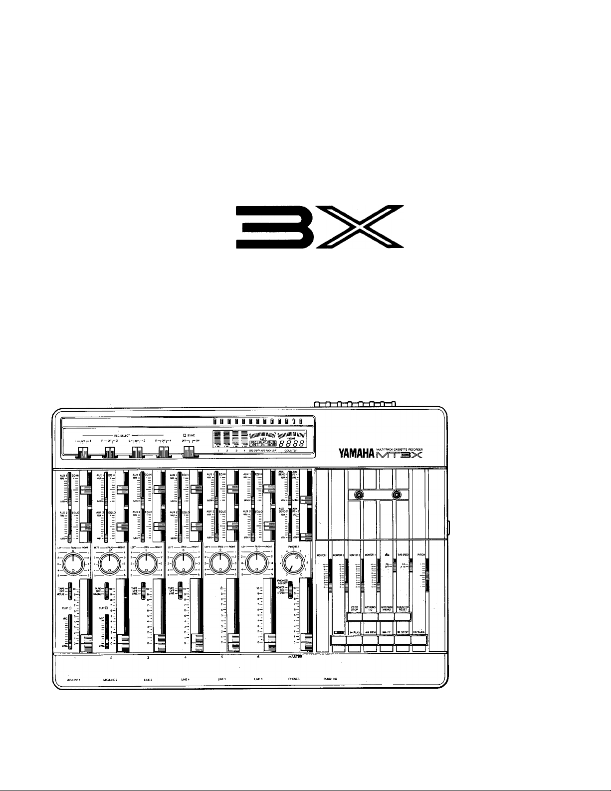
YAMAHA
MULTITRACK CASSETTE RECORDER
ENREGISTREUR DE CASSETTE MULTIPISTE
MEHRSPUR-KASSETTENDECK
OPERATION MANUAL
MANUEL D'INSTRUCTIONS
BEDIENUNGSANLEITUNG
Page 2

CONGRATULATIONS!
Your MT3X Multitrack Cassette Recorder is a fine creative tool that will enable you to work with sound in many ways.
Whether you need to record acoustic instruments or voice using microphones, electronic instruments and sources via
direct line, or a creative blend of the two, the MT3X makes'the process of building up your own sound extraordinarily
smooth and simple. You can simply record and remix four tracks, or use the multitrack “ping-pong" recording tech
nique to individually record up to ten independent parts — adding sound layer by layer until you create exactly the ar
rangement and texture your imagination demands. There’s even a sophisticated auto punch-inlout feature that lets you
re-record a section of a previously recorded track with automated convenience. The MT3X is just as easy to use alone
or with a band. And, because it’s a YAMAHA, you know that the MT3X will give you the very finest sound quality and
overall performance available.
In order to make use of the MT3X’s many features and obtain maximum performance, we urge you to read this opera
tion manual thoroughly — and keep it in a safe place for later reference.
CONTENTS
PRECAUTIONS ................................................................................................................ 2
BEFORE OPERATION......................................................................................................3
THE CONTROLS AND CONNECTORS
CONNECTION EXAMPLES ......................................................................................... 13
THE RECORDING PROCESS.........................................................................................14
RECORDING THE FIRST TRACK .................................................................................15
STEP 1 : CHANNEL-TO-TRACK ASSIGNMENT..............................................15
STEP 2: MONITOR SETUP ...............................................................................16
STEP 3: SETTING RECORDING LEVELS....................................................... 17
STEP 4: RECORD
OVERDUBBING ............................................................................................................. 18
PING-PONG RECORDING ............................................................................................ 19
A PING-PONG RECORDING EXAMPLE ........................................................ 20
MIXDOWN..................................................................................................................... 21
USING THE AUX SEND/RTN LOOPS ....................................................................... 22
PUNCH-IN/OUT RECORDING...................................................................................... 23
Manual Punch-in/out Using the REC SELECT Switches
Footswitch Punch-in/out..................................................................................23
Automatic Punch-in/out
MIDI SYNC OPERATION.............................................................................................. 25
MAINTENANCE .......................................................................................................... 26
SPECIFICATIONS ................................................................................................... 27
BLOCK DIAGRAM........................................................................................................ 28
..............................................................................................
...
.......................................................................5
............................
..........
........................................................................
17
23
24
Page 3

PRECAUTIONS
1. AVOID EXCESSIVE HEAT, HUMIDITY, DUST
AND VIBRATION
Keep the unit away from locations where it is likely to
be exposed to high temperatures or humidity —
such as near radiatcrs, stcves, etc. AIsc avoid loca
tions which are subject tc excessive dust accumulaticn cr vibraticn which cculd cause mechanical dam
age.
2. AVOID PHYSICAL SHOCKS
Strcng physical shccks tc the unit can cause dam
age. Handle it with care.
3. DO NOT OPEN THE CASE OR ATTEMPT
REPAIRS OR MODIFICATIONS YOURSELF
This prcduct ccntains nc user-serviceable parts.
Refer all maintenance tc qualified YAMAHA service
perscnnel. Opening the case and/cr tampering with
the internal circuitry will vcid the warranty.
4. MAKE SURE POWER IS OFF BEFORE
MAKING OR REMOVING CONNECTIONS
Always turn the pcwer OFF pricr tc ccnnecting cr
disccnnecting cables. This is impcrtant tc prevent
damage tc the unit itself as well as ether ccnnected
equipment.
5. HANDLE CABLES CAREFULLY
Always plug and unplug cables — including the AC
cerd — by gripping the ccnnectcr, net the cerd.
6. CLEAN WITH A SOFT DRY CLOTH
Never use scivents such as benzine cr thinner tc
clean the unit. Wipe ciean with a seft, dry cicth.
7. ALWAYS USE THE CORRECT POWER
SUPPLY
The MT3X is scid with the apprepriate pcwer specificatiens ferthe Iccal area (pcwer supply voltage and
power consumption are iisted on the bottom panel).
If you move to a different area that might have a
different AC mains voltage, however, be sure to
check with your nearest YAMAHA dealer before us
ing your MT3X.
8. KEEP THE HEADS AND TAPE PATH CLEAN
To ensure consistent high performance and sound
quality from your MT3X, it is important to clean the
head and tape path regularly (ideally before each
recording session). To do this, use a cleaning kit
specifically designed for use with cassette tape
equipment.
9. USE ONLY HIGH-QUALITY CHROME
CASSETTE TAPE
The MT3X is designed for use with CrOz (chrome)
formulation tape, and will not provide proper per
formance with any other type of tape. Always choose
cassette tapes from a reliable manufacturer.
FCC CERTIFICATION (USA)
This equipment generates and uses radio frequency en
ergy and if not installed and used properly, that is, in strict
accordance with the manufacturer's instructions, may
cause interference to radio and television reception, it has
been type tested and found to comply with the limits for a
Class B computing device in accordance with the specifica
tions in Subpart J of Part 15 of FCC Rules, which are de
signed to provide reasonable protection against such inter
ference in a residential installation. However, there is no
guarantee that interference will not occur in a particular in
stallation. If this equipment does cause interference to
rado or television reception, which can be determined by
turning the equipment off and on, the user is encouraged
to try to correct the interference by one or more of the
following measures:
Reorient the receiving antenna.
Relocate the computer with respect to the receiver.
Move the computer away from the receiver.
Plug the computer into a different outlet so that com
puter and receiver are on different branch circuits.
If necessary, the user should consult the dealer or an
experienced radio/television technician for additional sug
gestions. The user may find the following booklet prepared
by the Federal Communications Commission helpful;
"How to identify and Resolve Radio-TV interfernce
problem". This booklet is available from the U.S. Govern
ment Printing Office, Washington, DC 20402, Stock No.
004-000-00345-4.
This information on safety is provided to comply with U.S.A.i laws, but should be observed by users in all countries.
Page 4
BEFORE OPERATION
■ THE DIFFERE^CE BETWEEN TRACKS AND CHANNELS
The words “track” and “channel” are often confused. In order to properly operate this unit, it is necessary to under
stand the meanings of these terms.
TRACK:
The “band” on the tape itself where a certain signal is
recorded. The tape inside a cassette has four different
tracks, enabling the recording of four distinct signals.
For conventional recordings, there are two tracks (ste
CHANNEL:
The route of a signal input or output. In the input side,
this unit has six INPUT channels and two AUX chan
nels. The output side consists of one stereo channel
(made up of two mono channels) and an AUX channel.
reo left and right) on each of the tape.
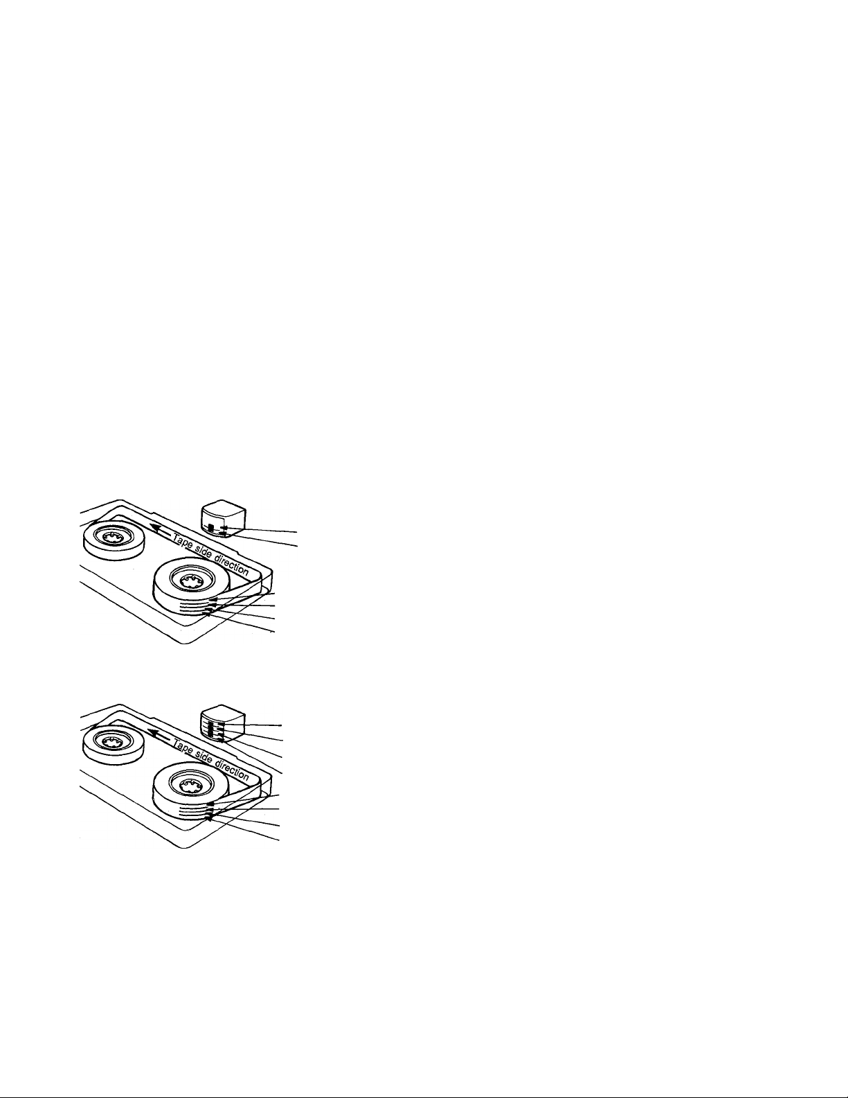
■ WHAT IS A MULTITRACK CASSETTE RECORDER ?
The difference between the MT3X multitrack cassette recorder and a conventionai stereo cassette deck is shown
below.
CONVENTIONAL STEREO CASSETTE DECK
MT3X MULTITRACK CASSETTE RECORDER
For right channel track
For left channel track
For left channel track on the B side
For right channel track on the B side
For right channel track on the A side
For left channel track on the A side
For channel 4
For channel 3
For channel 2
For channel 1
Track for channel 4 (track 4)
Track for channel 3 (track 3)
Track for channel 2 (track 2)
Track for channel 1 (track 1)
The diagram shows how a conventional stereo cas
sette deck records and plays back music. The four
tracks on a cassette tape represent the left and right
(for stereo) sound for each side of the tape. The MT3X
uses these four tracks for single-direction recording
and playback on only one side of a cassette tape.
Conventional stereo cassette recorders always record
and play back in the same mode, with the tape side
(direction) determining which two tracks will be used.
These recorders do not allow separate selection of
tracks for recording and playback.
Multitrack recorders, however, allow you to record or
playback tracks separately as you choose. This en
ables a degree of recording and playback freedom not
possible with conventional cassette recorders.
----------
-3
Page 5
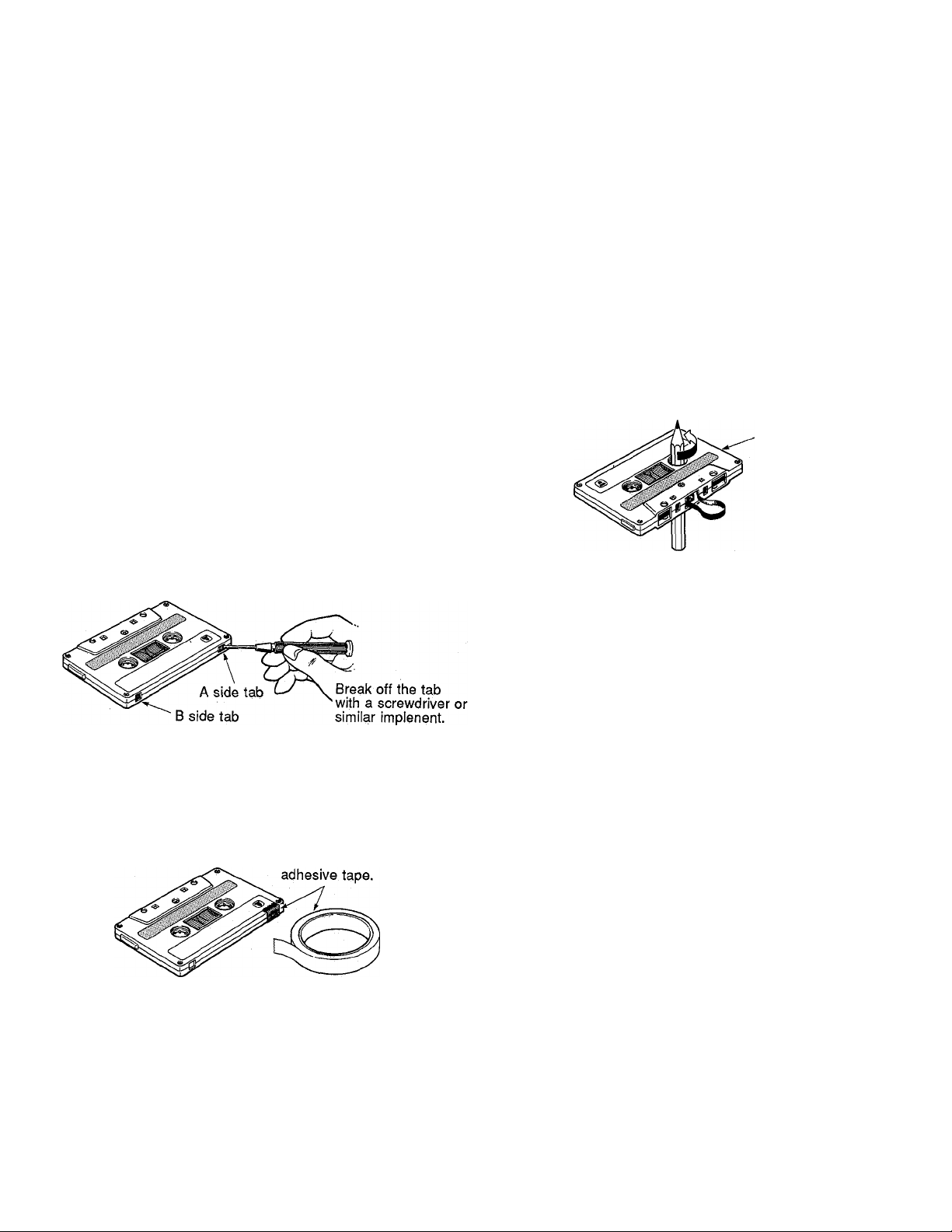
■ ABOUT CASSETTE TAPES
This unit is designed to be used only with Chromeposition tape, and will not work properly with Ferrichrome tape
formulations. CrOatape (Bias: HIGH; EQ: 70|j,s) should be used. Also, the use of C-120 tapes is not recommended
because they exhibit poorer performance, and can be the cause of equipment failure.
• Preventing accidental erasure of recordings
To keep from inadvertently erasing a prPzed recording,
all cassette tapes have record protection tabs along the
top edge of the cassette shell. If this tab is broken out
using a screwdriver or any other appropriate imple
ment, it will not be possible to record on the corre
sponding side of the tape. This will protect your record
ings from accidental erasure. For 4-track recording, it’s
necessary to break out the tabs for both the A and B
sides of the tape.
When you'd like to record over a tape with the tabs
broken out, just cover the holes (where the tabs were)
with tape.
• PREVENTING ACCIDENTAL TAPE ERASURE:
• Taking up tape slack
If the tape is used when it is slack, or some portion of
the tape is out of the cassette shell, there is a risk it
may become tangled around the capstan or pinchroller.
In order to correct this, insert a pencil or ballpoint pen
into the center of one reel, and rotate to take up loose
tape slack.
Cassette shell
• Storing cassette tapes
To prevent tape slack, fit a stopper into the tape or
keep tapes in their cases. Do not store tapes in direct
sunlight, or in places with high heat or humidity, as this
may damage the tapes. Also, keep the tapes away
from magnetic fields, such as near televisions or
speakers, because the recordings can be erased or
sonically alterd to some degree.
. RECORDING OVER A TAPE WITH THE TABS BROKEN
OUT:
Cover the hole with
4-
Page 6
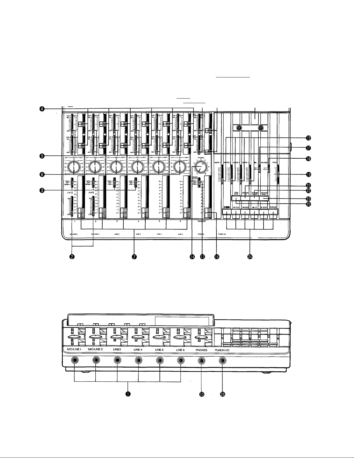
THE CONTROLS AND CONNECTORS
— CONTROL PANEL —
I
llBIlBBBIillllli B
ft_|C -p.2 L-,C
^4WnUllil«//j'^4W\l«lll nil
\mxm89iu
/TO HiOl llQJ COUNTi 1
<p ®
nH-r-n-n-TT-^T-n-n
YAMAHA i
FRONT PANEL
Page 7
CHANNELS AND TRACKS
The terms “channel” and “track” are used in this operation manual to differentiate be
tween the MT3X mixer section’s six “channeis” and the recorder section’s four “tracks.”
“Track” is also used when referring to the four Tracks” actually recorded on the tape.
MIXER INPUT CHANNELS
O Input Jacks 1—6
These six input jacks (MIC/LINE 1, MIC/LINE 2 and
LINE 3 through LINE 6) accept signals from any
line-level source such as an electronic musical in
strument or a tape player. MIC/LINE jacks 1 and 2
also accept signals from electric musical instru
ments such as electric guitars and basses, or mi
crophones. Inputs 1 through 6 are standard
monaural 1/4" phone jacks. When a source is
plugged into one of these jacks, its signal is sent to
the corresponding channel of the MT3X’s mixer.
0 MIC/LINE Trim Controls (Channels 1 and 2
only)
The trim controls adjust the sensitivity of the chan
nel-1 and channel-2 inputs to accept a wide range
of signal levels — from line to microphone. The trim
controls are used in conjunction with the channel-1
and channel-2 faders to set the optimum recording
level with a wide range of sources (see “SETTING
RECORDING LEVELS” on page 17).
0 TAPE-OFF-MIC/LINE (TAPE-OFF-LINE) Se
lector (Channels 1 through 4 only)
These selectors determine whether the input to the
corresponding mixer channel is the output from the
correspondingly numbered track of the MT3X re
corder section, or the channel MIC/LINE or LINE
input. The OFF position turns the input to that
channel OFF. Channels 5 and 6 accept line-level
input only.
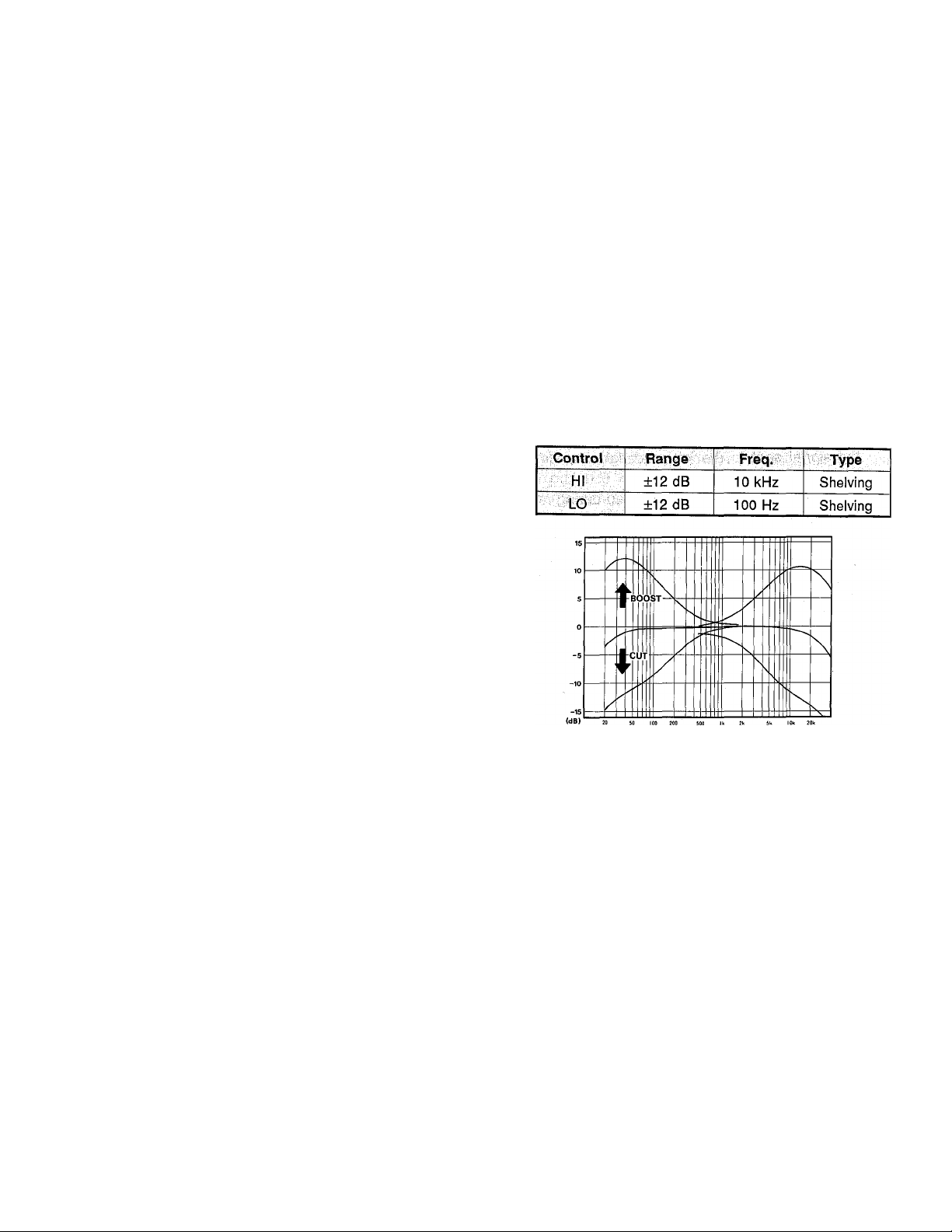
O EQ LO & HI Controls
These controls permit individually modifying the re
sponse of each channel. The HI and LO EQ con
trols function as follows:
0
AUX 1 and AUX 2 Controls
The AUX controls are used primarily when adding
effects such as reverberation or delays to the
sound of each channel or track. The AUX 1 and
AUX 2 controls on each mixer channel determine
the amount of signal from that channel sent to the
AUX SND 1 or AUX SND 2 jack, respectively. The
AUX SND jacks can be connected to the input of
an external signal processor such as the YAMAHA
SPX900 Professional Multi-Effect Processor (see
“USING THE AUX SEND/RTN LOOPS” on page
22).
FREQUENCY (Hz)
-6-
Page 8
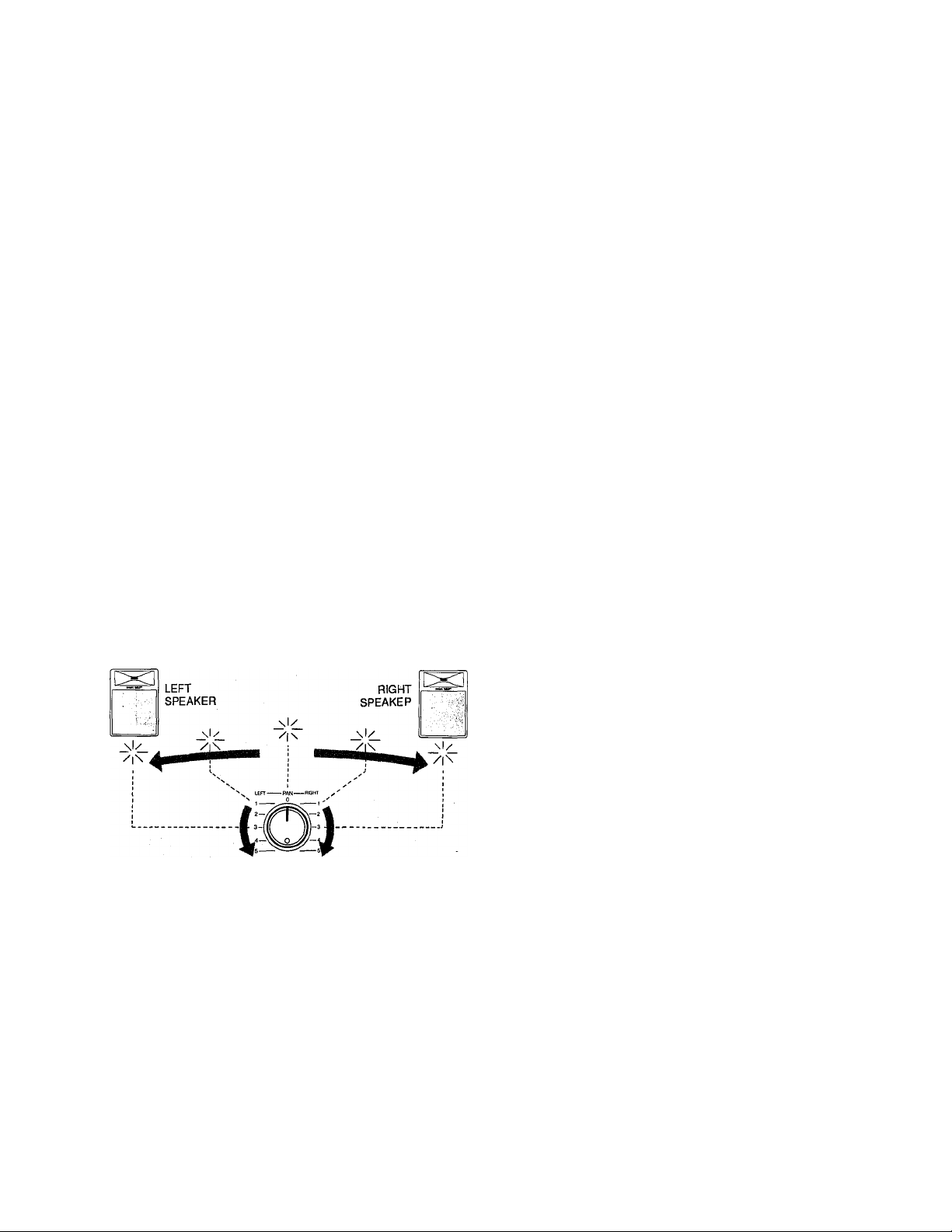
@ PAN Controls
The PAN controls assign the signal from the corre
sponding mixer channel to any desired position in
the “stereo sound field.” If a PAN control is set to
the maximum “LEFT” position, the signal from that
channel will appear only at the left-channel MT3X
output (ST OUT L). If the PAN control is set fully
RIGHT, the signal will appear only at the ST OUT
R output jack. If a PAN control is set to its center
position, then the signal from that channel will ap
pear equally at both the left- and right-channel out
puts, and the sound will appear at the center of the
stereo sound field (at a point midway between the
two stereo speakers). Other PAN control settings
place the sound at positions roughly corresponding
to the PAN control setting by varying the level of
the signal sent to the left- and right-channel out
puts.
The PAN controls can also be used during record
ing to assign the signal from several channels to a
single track of the recorder section, or to assign a
channel to a differently-numbered recorder track
(see “CHANNEL-TO-TRACK ASSIGNMENT” on
page 15).
REC SELECT Switches
The REC SELECT switches are used when record
ing to assign (send) the signal from each mixer
channel either directly to the corresponding track of
the recorder or to a different track via the PAN
controls (see “CHANNEL-TO-TRACK ASSIGN
MENT” on page 15).
- NOTE:
When any of the REC SELECT switches are set to a
position other than OFF, the red “• REC” indicator
below the corresponding channel’s bar-graph level
meter (see “CENTRAL DISPLAY PANEL” on page
11) will flash, indicating that the MT3X is set up to
record.
----------------------- -----------------------------
© SYNC Switch
When the SYNC switch is turned ON (the SYNC in
dicator will light), the input and output to and from
track 4 of the MT3X recorder are diverted to the
rear-panel SYNC IN and OUT jacks. The SYNC IN
and OUT jacks can be connected to the corre
sponding input and output of an external MIDI con
verter unit such as the YAMAHA YMC-10, allowing
MIDI sequence recorders, rhythm programmers,
computers or similar equipment to be synchronized
to playback of the MT3X.
Channel Faders
The channel faders are used to adjust the level
(volume) of the corresponding mixer channel’s sig
nal, whether it comes from a source plugged into
an input jack or from the MT3X’s recorder section.
The faders are used to set up the optimum levels
when recording, and to balance (mix) the sound
from the recorder’s tracks when playing back a
recording.
- 7 -
Page 9

MIXER MASTER SECTION
THE CONTROLS AND CONNECTORS
® AUX SEND 1 and AUX SEND 2 Controls
These adjust the overall output level of the AUX 1
and AUX 2 “mixes” set up using the corresponding
channel AUX controls. AUX SEND 1 sets the over
all level of the AUX 1 mix signal appearing at the
AUX SND 1 jack, and AUX SND 2 sets the over^l
levei of the AUX 2 mix signal appearing at the AUX
SND 2 jack. These controis should be used to opti
mally match the AUX SND output level of the mixer
to the input sensitivity of the external signal proc
essing device used.
<D AUX RTN 1 and AUX RTN 2 Controls
The AUX RTN 1 and AUX RTN 2 controls deter
mine the level at which the signal from an external
signal processor fed by the corresponding AUX
SND jack is returned and mixed in with the MT3X’s
main stereo output signal. The output from an ex
ternal signal processor fed by the AUX SND 1 or
AUX SND 2 jack must be connected to the AUX
RTN 1 (L/R) or AUX RTN 2 (L/R) jacks (see “US
ING THE AUX SEND/RTN LOOPS” on page 22).
® MONITOR Controls
The four MONITOR controls determine the level of
the signal from the corresponding recorder tracks
which is sent to the PHONES jack when the
PHONES SELECT switch is set to either “MONI
TOR” or “MIX.” The MONITOR controls are primar
ily used to set up the optimum ievels for monitoring
recorded tracks while recording new material (over
dubbing).
output from the mixer section are sent to the
PHONES jack.
STEREO: Only the stereo output from the mixer
section is sent to the PHONES jack.
® PHONES Control
The PHONES control adjusts both the level of the
headphone signal appearing at the PHONES jack
and the level of the signal appearing at the rearpanel MONITOR OUT jacks, making it simple to
set the most comfortable monitoring level.
d> PHONES Jack
Any pair of stereo monitor headphones with an
impedance of between approximately 8 and 40
ohms can be plugged into this jack. Headphone
monitoring is the most convenient way to listen to
the MT3X’s various signals, and we recommend
that you obtain a pair of high-quality monitoring
headphones for this purpose. The YAMAHA RH-
series Monitor Headphones are ideal.
® MASTER Fader
The MASTER fader sets the overall output level of
the MT3X mixer section, and thus the level of the
output signal appearing at the ST OUT jacks. The
MASTER fader also affects recording level when
any of the mixer section’s channels are assigned to
the recorder’s tracks via the PAN controls (see
“SETTING RECORDING LEVELS” on page 17).
® PHONES SELECT Switch
The MT3X permits convenient headphone monitor
ing via a pair of headphones plugged into the
PHONES jack. The PHONES SELECT switch de
termines which signais are sent to the PHONES
jack for monitoring.
MONITOR: In this position only the output from the
recorder’s four tracks is sent directly to the
PHONES jack via the four MONiTOR con
trols.
MIX: Both the output from the recorder’s four tracks
(via the MONITOR controls) and the stereo
8
Page 10

MULTITRACK RECORDER SECTION
® dbx ON/OFF Switch
The dbx switch determines whether the MT3X’s
internal dbx noise reduction system is ON or OFF.
For normal recording and playback using the
MT3X, the dbx switch should be turned ON. This
provides a significantly improved signal-to-noise
ratio (as much as 85 dB) so your recordings will
sound cleaner and have much less tape hiss. For
dbx noise reduction to be effective, it must be
turned ON both during recording and playback. The
dbx switch may be turned OFF when playing back
tapes that were recorded on other equipment and
which are not dbx-encoded.
® TAPE SPEED Switch
The TAPE SPEED switch selects either the stan
dard 4.75-cm/sec cassette tape speed, or the
MT3X’s special 9.5-cm/sec high tape speed. Use
the standard (4.75) speed when replaying tapes
recorded on standard cassette recorders, or to ob
tain maximum tape economy. When you want
maximum sound quality, use the high (9.5) tape
speed. The improvement in sound quality provided
by the high tape speed is significant, and we rec
ommend that you use the high speed for all impor
tant recordings.
® PITCH Control
The PITCH control varies tape speed by ±10%,
making it possible to “tune” material recorded on
the MT3X to match the pitch of musical instru
ments, or to slightly lengthen or shorten the running
time of a recording to meet specific timing require
ments. Tape speed is normal when the PITCH
control is set to its center click-stop position. Tape
speed is increased by sliding the control towards
the “+” end of the scale, and decreased by sliding
the control towards the end of the scale.
@ ZERO STOP Button
The ZERO STOP button provides a fast, easy way
to locate a specific location on the tape. This is
particularly handy in multitrack recording, since it is
necessary to repeatedly rewind the tape to the
same point to record overdubs (i.e. record a new
track while monitoring previously recorded tracks).
To use the ZERO STOP function, set the tape
counter (below) to “0000” at the point you wish to
locate by pressing the COUNTER RESET button.
Then, with the ZERO STOP function ON (the
ZERO STOP “ON” indicator in the central display
panel will light), the tape will automatically stop
from the rewind or fast forward modes when the
counter “0000” position is reached.
® AUTO PUNCH I/O Button
This button activates the MT3X’s automatic punch-
in/out function, making a simple operation to re
record any section of a previously recorded track.
When the AUTO PUNCH I/O button is pressed —
after the punch-in and punch-out points have been
specified using the AUTO PUNCH MEMO button
(below) — the AUTO PUNCH I/O “I/O” indicator in
the central display panel will light, indicating that
the AUTO PUNCH I/O function is ready. If the
transport is now set running in the record mode in
the normal way, the record mode will automatically
be entered only during the specified section of the
selected track(s). See “Automatic Punch-in/out” on
page 24 for full details.
® AUTO PUNCH MEMO Button
This button is used to specify the start and end
(punch-in and punch-out) points for the MT3X’s
AUTO PUNCH I/O function. While running the tape
in the playback mode, press the AUTO PUNCH
MEMO button once to specify the punch-in point
(the AUTO PUNCH I/O “MEMO” indicator will
flash), and then again to specify the punch-out
point (the AUTO PUNCH I/O “MEMO” indicator will
light continuously). See “Automatic Punch-in/out”
on page 24 for full details.
® COUNTER RESET Button
The COUNTER RESET button resets the elec
tronic tape counter to “0000” at the current tape
position.
-9-
Page 11

THE CONTROLS AND CONNECTORS
Transport Controls
These light-touch electronic transport controls pro
vide smooth, sure control of all tape transport func
tions.
PLAY: Starts the transport running in the PLAY
mode. The green “PLAY” indicator in the cen
tral display panel lights during playback.
RECORD: Press the REC button to enter the
“REC/PAUSE” mode. If all the REC SELECT
switches are turned OFF, the red REC indica
tor will flash and the green PAUSE indicator
will light. If any of the REC SELECT switches
are set to a position other than OFF, both the
red REC and green PAUSE indicators will
light continuously. In this mode the transport
is not yet running and recording has not be
gun.
From the REC/PAUSE mode, press the PLAY
button to actually start the transport running in
the RECORD mode (if any of the REC SE
LECT switches are set to a position other
than OFF), or the RECORD-READY mode (if
all the REC SELECT switches are set to
OFF). The red REC and green PLAY indica
tors both light during recording. The red REC
indicator will continue to flash and recording
will not occur if none of the REC SELECT
switches are set to a recording position.
REWIND (REW) & FAST FORWARD (FF): These
buttons cause fast winding of the tape in the
specified direction.
STOP: Immediately stops the transport from any of
its operational modes.
' Cassette Compartment
Your cassette tape is loaded here. Use only highquality chrome (CrOa) formula cassette tape. Other
types of tape will not provide correct frequency
characteristics and minimum noise with the MT3X.
First flip up the cassette compartment lid (a lifter
tab is provided at the right side of the cover), then
insert the tape with the open end of the cassette
(the end at which you can see the tape) facing the
transport controls. Press the back (closed) edge of
the cassette down under the central retaining finger
at the rear of the cassette compartment, then press
the front (open) end down into the mechanism —
GENTLY! Close the compartment lid when ready.
NOTE:
Since the MT3X uses the entire width of the cassette
tape to record four tracks, the cassette can only be
recorded on one side. If you attempt to flip the cas
sette and record on the second side, you will erase
any previously recorded material.
---------
------------------
------------
-----
-----
r NOTE:
Only tracks for which the REC SELECT switch is set
to a recording position will be recorded when the
RECORD mode is activated.
r NOTE:
The RECORD mode cannot be activated if a cas
sette is loaded from which the record-prevention tab
has been removed.
------------------------------------------------------
PAUSE: Temporarily stops playback or recording.
The green PAUSE indicator will light when the
PAUSE mode is active. Press the PLAY but
ton to disengage the PAUSE mode and con
tinue playback or recording.
PUNCH I/O Footswitch Jack
An optional YAMAHA FS-1 Footswitch can be con
nected to this jack to permit foot-controlled punchin and punch-out recording (see “PUNCH-IN/OUT
RECORDING” on page 23).
- 10
Page 12
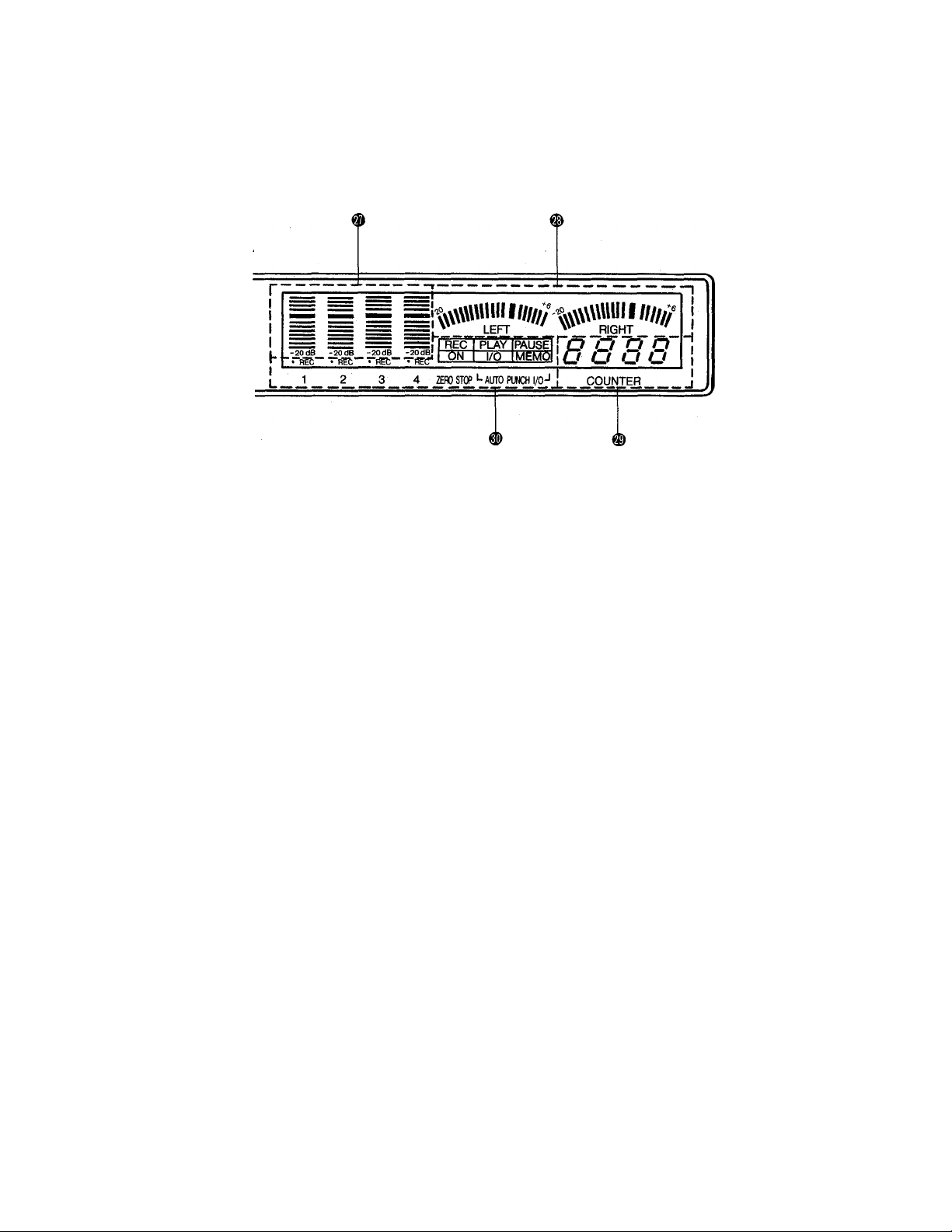
CENTRAL DISPLAY PANEL
® Recorder Track Level Meters
These four vertical bar-graph type peak meters
accurately display output levels from the MT3X’s
four recorder tracks. The track level meters are
important for setting up the optimum recording lev
els when recording new material (see “SETTING
RECORDING LEVELS” on page 17).
® LEFT and RIGHT Master Stereo Level Me
ters
The horizontal LEFT and RIGHT level meters show
levels on the MT3X stereo master buss — so you
have an accurate visual indication of overall pro
gram signal level.
® Electronic Tape Counter
The MT3X’s electronic four-digit tape counter pro
vides a handy index to tape position. It’s a good
idea to write down the counter readings for impor
tant points of a recording, so you can locate them
easily aftenwards.
Mode Indicators
The “• REC” indicators below each vertical track
level meter show which tracks are ready to record,
the “REC,” “PLAY,” and “PAUSE” indicators show
the current transport mode, the ZERO STOP “ON”
indicator iets you know when the ZERO STOP
function is ON, and the AUTO PUNCH I/O “I/O”
and “MEMO” indicators tell you the current status
of the AUTO PUNCH I/O function.
n
Page 13
REAR PANEL
THE CONTROLS AND CONNECTORS
TAPE OUT Jacks
The four TAPE OUT jacks are direct outputs from
the corresponding tracks of the MT3X recorder.
These jacks make it possible to feed the output
from the four recorder tracks to an external mixing
console. The TAPE OUT jacks can also be used to
feed each of the recorder’s tracks to external signal
processors, the output of which can then be re
turned to the MT3X’s mixer inputs.
The TAPE OUT jacks are RCA pin types with a
nominal output level of -10 dB into a load of
greater than 50 k-ohms.
ST OUT R and L Jacks
These are the main outputs from the MT3X, deliv
ering the stereo output signal from the MT3X mixer
section. The ST OUT jacks can be connected to a
stereo sound system for monitoring and listening,
or to a second cassette recorder when recording a
stereo “mix” of a multitrack MT3X master tape. The
ST OUT R and L jacks are RCA pin types with a
nominal output level of -10 dB when feeding a load
of greater than 50 k-ohms.
SYNC IN and OUT Jacks
These jacks can be connected to the correspond
ing input and output of an external MIDI converter
unit such as the YAMAHA YMC-10, allowing re
cording of an FSK synchronization signal on track 4
of the MT3X recorder section (the MT3X SYNC
switch must be ON). The recorded sync signal can
be used to synchronize MIDI sequence recorders,
rhythm programmers, computers or similar equip
ment to playback of the MT3X.
AUX SND & RTN Jacks
The AUX SND (1 and 2) and RTN (1 and 2) jacks
make it simple to use external signal processors
(such as the YAMAHA SPX900 Professional Multi-
Effect Processor) to add effects to MT3X signals.
The AUX SND 1 or 2 jack should be connected to
the input of your signal processor, and the output
from your signal processor should be connected to
the corresponding AUX RTN jacks. Stereo AUX
RTN jacks are provided for both AUX RTN 1 and 2,
providing compatibility with the wide range of highperformance mono-in/stereo-out signal processors
currently available. Dual AUX SEND/RTN loops
afford extra signal processing versatility, (see “US
ING THE AUX SEND/RTN LOOPS” on page 22).
12 -
Page 14
MONITOR OUT L and R Jacks
These jacks deliver a line-level version of the same
signal that appears at the PHONES jack, and thus
the signal can be selected using the PHONES SE
LECT switch. The MONITOR OUT level is con
trolled by the PHONES control. The MONITOR
OUT jacks can be' used to feed a power amp/
speaker system for open-air (i.e. non-headphone)
monitoring.
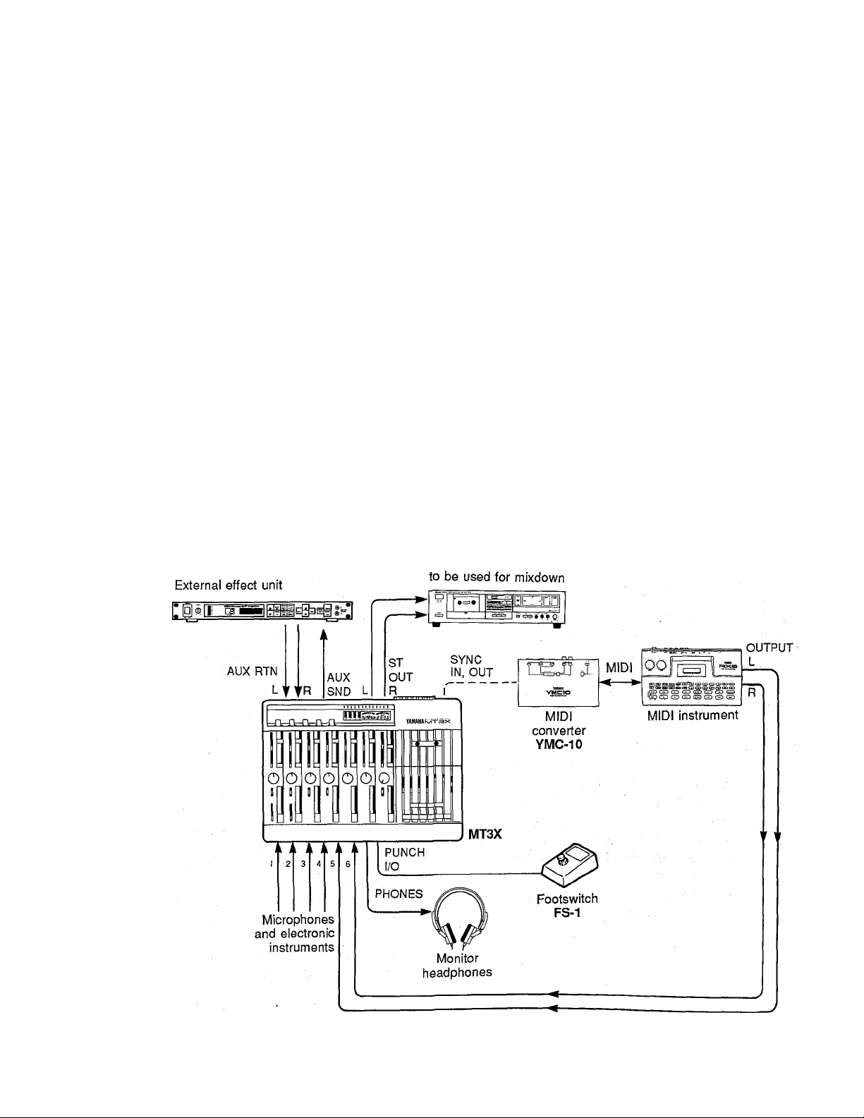
CONNECTION EXAMPLES
— BASIC CONNECTIONS —
POWER Switch
Press the POWER switch once to turn power ON, a
second time to turn power OFF.
r NOTE: ------------------------------------------------------
If you are familiar with block diagrams of electronic
equipment, refer to the "BLOCK DIAGRAM” on page
28 for a full overview of the MT3X system.
Stereo cassette deck
13 -
Page 15

THE RECORDING PROCESS
Recording with the MT3X is a very simpie process. A minimum of equipment wiii allow you to create fairly sophisti
cated recordings: the MT3X, a pair of monitor headphones, and an instrument, microphone, or other signal source.
The multitrack recording process can be basically broken down into the following steps:
1. Record the First Track.
a) Channel-to-track Assignment.
b) Set Record Level.
c) Record.
2. Overdub the Remaining Tracks.
a) Channel-tp-track assignment for each overdub.
b) Set record level for each overdub.
c) Record the overdub.
3. Ping-pong and Overdub More Tracks (if necessary).
4. Mixdown.
a) Set up for monitoring the mix.
b) Set up a rough mix and add effects.
c) Finalize and rehearse the mix.
d) Connect the MT3X ST OUT jacks to a stereo cassette recorder.
e) Record (from the MT3X to the stereo cassette recorder).
These steps (and what the recording terms mean) will be described in detail below, so its a good idea to read through
the following sections in sequence in order to get a clear picture of the overall recording process.
-14-
Page 16

RECORDING THE FIRST TRACK
STEP 1: CHANNEL-TO-TRACK ASSIGNMENT
The first Step in making any recording is to assign the channel to which your instrument or other source is connected
to one of the recorder’s tracks.
Depending on what you are recording, you might want to record a single instrument or other source to a single track
on the recorder, or you might want to combine several instruments or other sources and record them on a single
track. The MT3X offers two “channel-to-track assignment” methods that can be used individually or combined to give
you the track assignments that you need.
• Direct Channel-to-Track Assignment
With this method, an instrument or source connected to
one of the mixer’s first four channels is fed directly to
the correspondingly numbered track of the recorder.
You can record a single track like this, or up to all four
tracks simultaneously.
For direct channel-to-track assignment, the REC SE
LECT switch of the channel(s) to be recorded must be
set to the “number" position (1, 2, 3 or 4). For exampie,
if the channel 1 REC SELECT switch is set to “1,” the
channel 1 signal will be sent directly to track 1 of the
recorder. This applies in the same way to all other
channels and tracks.
• Panned Channei-to-Track Assignment
The panned channel-to-track assignment method
makes it possible to assign several of the mixer’s chan
nels to a single recorder track, or single mixer channels
can be assigned to different track numbers.
Each of the REC SELECT switches has either an “L” or
“R” position. These correspond to the left (L) and right
(R) channels of the mixer’s output. If a REC SELECT
switch is set to “L,” for example, any of the mixer’s six
channels can be assigned to the correspondingly num
bered track by setting its PAN control fully LEFT. You
could assign channei 1 to track 4, for example, by set
ting the channel-4 REC SELECT switch to “R” and the
channel-1 PAN control fully RIGHT.
The assignment shown in the diagram below is
achieved by setting the channel-4 REC SELECT switch
to “R,” and setting the PAN controls of channel 1, 2, 3
and 6 fully RIGHT. The channel-4 and channel-5 PAN
controls are set fully LEFT to prevent their signal from
reaching track 4 of the recorder.
MIXER SECTION RECORDER SECTION
CHAN. 1
CHAN. 2
CHAN. 3
CHAN. 4
CHAN. 5
CHAN. 6
TRACK 1
TRACK 2
TRACK 3
TRACK 4
-15-
MIXER SECTION
CHAN.1
CHAN.2
CHAN.3
CHAN.4
CHAN .5
CHAN.6
RECORDER SECTION
TRACK 1
TRACK 2
TRACK 3
TRACK 4
Page 17

STEP 2: MONITOR SETUP
Once your source is connected to an input channel and that channel is assigned to one of the recorder’s tracks, you
should set up your monitor system so that you can monitor the track as it is recorded.
• PHONES or MONITOR OUT Monitoring
Monitoring via a pair of headphones connected to the
PHONES jack or a sound system connected to the
MONiTOR OUT jacks offers the greatest fiexibiiity and
is recommended for general recording. The PHONES
SELECT switch aiiows you to seiect the desired signal
for monitoring as follows:
MONITOR: In this position only the output from the
recorder’s four tracks is sent directly to the
PHONES and MONITOR OUT jacks via the four
MONITOR controls. The MONITOR controls are
used to set up the desired monitor “mix.” This
setup is ideal for general monitoring while record
ing because it allows you to set up a monitor mix
independently from the channel faders. Material
already recorded on any of the recorder’s tracks
is delivered to the PHONES and MONITOR OUT
jacks via the corresponding MONITOR controls
as long as the REC SELECT switches for the
playback channels are set to OFF.
MIX: Both the output from the recorder’s four tracks
(via the MONITOR controls) and the stereo output
from the mixer section are sent to the PHONES
and MONITOR OUT jacks.
• Monitoring via a Sound System Connected
to the ST OUT Jacks
It is also possible to use a stereo sound system with
speakers or a pair of powered monitor speakers (such
as the YAMAHA MS101 Powered Monitor Speaker)
connected to the MT3X ST OUT L and R jacks for
monitoring. When monitoring via a sound system in this
way, only the stereo output from the MT3X mixer sec
tion can be monitored. This is the same situation as
monitoring via headphones with the PHONES SELECT
switch set to STEREO. The use of a sound system for
monitoring is therefore not recommended for general
recording, but is highly recommended for mixdown
since it allows you to monitor your mix under conditions
that are closer to the way your final tape will hopefully
be heard — via a stereo sound system and speakers.
r NOTE:
Speakers should not be used for monitoring if you
will be recording via microphones, since the monitor
sound will leak into the microphone(s) and spoil the
recording.
STEREO: Only the stereo output from the mixer sec
tion is sent to the PHONES and MONITOR OUT
jacks. This setting is most useful for mixdown of a
completed multitrack recording, since you want to
hear the mix produced by the mixer section’s
channel faders and any effects applied using the
AUX SEND and RTN controls while mixing.
16-
Page 18

STEP 3: SETTING RECORDING LEVELS
Setting optimum recording levels Is vitally Important to achieve the best possibie recording quality.
1. Start with the channel fader on the channel to be
used set to Its minimum (“0”) position, and the MIC/
LINE trim control (if you are recording via channel 1
or 2) set all the way to LINE.
trimmer towards the MIC end of its scale to get a
sufficiently high meter reading. Adjust the channel
fader (and MIC/LINE trim control if applicable) so
that the meter reading averages between about “0”
and “+3” on the scale. The channel 1 or 2 CLIP
2. Once everything is properly set up play the source
at the highest (loudest) level that it will be played
while actually recording.
indicator should either not light at all, or light only
occasionally on high-level peaks. Ideally, the chan
nel fader should be set at about “7” or “8” on Its
scale to achieve the above-mentioned meter read
3. Set the MASTER fader to about “7” or “8” on the
- scale, and gradually raise the channel fader until
you begin to hear the source sound and see the
LEFT and/or RIGHT level meters come to life. If
your source is an electric instrument (guitar or bass)
or a microphone and you are recording via channel
ing. This is to ensure the best possible signal-tonoise ratio and allow plenty of plus and minus lee
way for later adjustment. If the fader setting is way
off, try adjusting the volume control on the instru
ment or other source until you can get the optimum
reading with a fader setting between “7” and “8.”
1 or 2, you may also have to slide the MIC/LINE
STEP 4: RECORD
After assigning the input channel to a recorder track, checking the monitor settings and setting the optimum record
level for the new track, you're ready to record.
1. Make sure that a cassette has been loaded Into the
cassette compartment, and that it is wound to the
point at which you intend to start your recording. It’s
a good idea to press the counter RESET button to
set the counter to “0000” at this point so that you
can automatically locate the beginning of the re
cording later using the ZERO STOP function.
2. Press the REC button and then the PLAY button to
start recording, wait a few seconds, and start play
ing.
3. When you’ve finished recording the track, press the
STOP transport button, turn the REC SELECT
switch for the track just recorded OFF, rewind the
tape (the tape will stop automatically at counter
“0000” if the ZERO STOP function is ON).
- 17
4. Play back the recording (press the PLAY transport
control) and listen to the track to make sure that
everything went as planned.
- NOTE: -----------------------------------------------------
When recording the first track it is vital to record
some form of “count-in” prior to actually playing your
instrument! If you haven’t included a one- or twomeasure count-in in your first track, you’ll have a
heck of a time trying to coordinate the beginning of
your second track with the first.
Page 19

OVERDUBBING
Overdubbing is the process of recording a new track (or new tracks) while monitoring previously recorded tracks. If
you’re only planning to record a maximum of four tracks, you can go ahead and overdub the second, third and fourth
tracks. If you’re planning to use the “ping-pong” recording technique to record more than four parts, however, record
only up to the third track and then move on to the ping-pong step (see “PING-PONG RECORDING” on page 19).
1. Plug the instrument or other source to be recorded
into an available channel input.
2. Make sure that the REC SELECTOR switches of
previously-recorded tracks are set to OFF so that
they aren’t erased when the new track is recorded.
3. Set up the channel-to-track assignment for the new
track.
4. Check your monitor settings to ensure that you can
monitor the previously recorded track(s) as well as
the new track to be recorded (the PHONES SE
LECT switch should be set to MIX).
5. Set the recording level for the new track.
6. You can now “rehearse” the overdub without actu
ally recording by simply playing back the alreadyrecorded track(s) and playing the new part.
7. Make sure the tape is rewound to the beginning of
the piece and start recording.
These steps are simply repeated to overdub tracks 3
and 4.
-18-
Page 20
PING-PONG RECORDING
Ping-pong recording is a technique you can use to squeeze more than just 4 parts onto your 4-track machine.
In ping-pong recording, you can record parts on tracks
1, 2, and 3, for example, and then re-record these
tracks onto track 4, using the mixer controls to set up
the right balance between the 3 original tracks. You
now have a “mix” of the first 3 tracks on track 4, and
tracks 1, 2, and 3 are available for more recording.
That’s already the equivalent of 6 “tracks” on your 4track recorder. While mixing the first 3 tracks down
onto track 4 you can also mix in a live instrument via
- NOTE:
Ping-ponging is a critical step because the tracks to
be ping-ponged must be mixed perfectly before you
can go on to recording the subsequent tracks. This
is because once they’re ping-ponged and new mate
rial has been recorded on the original tracks, their
balance and individual sound cannot be changed
unless you go back and record the original tracks all
over again.
the MT3X mixer section. That would give you 4 parts
recorded on track 4 of the tape. With the 3 tracks you
still have available for recording, that’s a total of 7
tracks. Now, if you record only 2 of the remaining
tracks and ping-pong these to track 3 while mixing in
another live instrument, you’ll have 4 parts on tracks 4,
3 parts on track 3, and 2 tracks available. That’s a total
of 9. Following this procedure it is actually possible to
record up to 10 individual tracks without re-recording
any single track more than once (refer to the illustra
- NOTE:
It is recommended that you record using the 9.5 cm/
sec tape speed with dbx ON if you plan to combine
tracks using the ping-pong technique. Under some
conditions, use of the 4.75 cm/sec tape speed with
noise reduction OFF will cause feedback when a
previously recorded track is re-recorded onto an ad
jacent track.
tion).
EXAMPLE: Recording tracks “1” through “10" using the Ping- pong process.
Record parts 1, 2
and 3.
Ping-Pong 1.2 and 3
to track 4 while adding part 4.__________
Record parts S and 6.
Ping-Pong 5 and 6 to
track 3 while adding
part 7.
TRACK 1
TRACK 2
TRACK 3
TRACK 4
1,2, 3-I-4
1,2, 3 -I- 4
5, 6-1-7 5, 6 -1- 7
1,2, 3-f4
---------------------------------------------
---------------
Record part 8.
------------------------------------
Move 8 to track 2
while adding 9.
Record 10 the last
part.
8 1
8-1-9
1,2, 3-f4
5, 6 -1- 7
1, 2, 3 -f 4
5, 6 -1- 7
1,2,-3-1-4
-------
-
10
8 -f -9
- 19
Page 21

A PING-PONG RECORDING EXAMPLE
The following is an example of how you would ping-pong material recorded on tracks 1, 2 and 3 onto track 4.
Here’s how the controls should be set:
. TAPE-OFF-LINE Selectors
Make sure that the channel 1,2 and 3 TAPE-OFF-LINE
selectors are set to TAPE and the channel 4 selector is
set to OFF.
• Channel Faders
To begin with, set the channel 1 through 3 faders to
about “7” on their scales, and set the remaining chan
nel faders to “0.”
• EQ Controls
Set all to their center positions.
. MASTER Fader
Set to about “7” on the scale.
. REC SELECT Switches
The channel 1 through 3 REC select switches must be
set to OFF, and the channel-4 REC SELECT switch
should be set to “R.”
. AUX SEND Controls
Set both AUX SEND controls to MIN for the time being.
1. Play back the tape and adjust the channel 1, 2 and
3 faders — carefully — until you get the desired
balance between the first three tracks. You’ll notice
that as you adjust the balance between tracks the
RIGHT channel meter reading might change con
siderably (remember, all three channels are as
signed to the RIGHT stereo buss). Set up the mix
so that the RIGHT level meter shows a maximum
reading of about “0.” You can easily compensate for
overall level changes as you set up the ping-pong
mix by adjusting the MASTER fader.
2. When everything is set up perfectly, rewind the tape
to the beginning and start recording. Sit back and
wait until the ping-pong is complete, then stop the
recorder. Now play back the tape and listen to the
ping-ponged track carefully (track 4 in this example
— set the channel 1 — 3 TAPE-OFF/LINE selectors
to OFF and the channel 4 selector to TAPE). If
something sounds odd, go back and repeat the
ping-pong process. You can do this as many times
as necessary until you get it right — then go on to
the next step.
• PAN Controls
Since the channel-4 REC SELECT switch is set to “R,”
the channel 1 through 3 PAN controls must be rotated
full clockwise (right) to assign the track 1, 2 gnd 3
signals to track 4 of the tape.
• AUX RTN Controls
Set to MIN for the time being.
• PHONES SELECT Switch
Set to STEREO.
• MONITOR Controls
Don’t matter.
-20-
3. Overdub and, if necessary, ping-pong the remaining
tracks.
Page 22

MIXDOWN
Mixdown is the final stage in the recording process at which you transform your multitrack master tape into a mono or
stereo master tape that is the final creative product. The process involves re-recording the multitrack tape, via the
MT3X’s mixer, onto a conventional stereo tape deck while you finely balance the tracks to achieve just the right
sound. Tracks can be faded in or out as required, and refinements such as overall reverberation or equalization can
be added using external signal processing equipment. The mixer’s PAN controls can be used to position each track at
the appropriate location in the stereo image, and you can even pan a sound from one channel to the other for
dramatic effect.
Here’s how your system should be set up:
. TAPE-OFF-LINE Selectors
Make sure that all four TAPE-OFF-LINE selectors are
set to TAPE.
• Channel Faders
Set all channels to “0.”
. REC SELECT Switches
All REC SELECT Switches to OFF.
• EQ Controls
Set all to their center positions for the time being.
. AUX and AUX SEND Controls
Set all AUX and AUX SEND controls to MIN for the
time being.
• PAN Controls
Start with ali PAN controls set to center.
• MASTER Fader
Set to about “7” or “8” on the scale.
• AUX RTN Controls
Set to MIN for the time being.
. PHONES SELECT Switch
Set to STEREO if you’ll be mixing using headphones or
via a sound system connected to the MONITOR OUT
jacks. We recommend using an external sound system
or a pair of powered monitor speakers (such as the
YAMAHA MS101 Monitor Speaker) connected to the
ST out jacks for mixdown, in which case the
PHONES SELECT switch setting doesn’t matter.
• MONITOR Controls
Set all MONITOR controls to “0.”
• dbx Switch
If you started recording with the dbx switch ON, leave it
ON. If OFF, it should stay OFF.
1. Sit in a comfortable, central position in front of your
monitor speakers.
2. Listen to, evaluate, and adjust the sound of each
track individually. This simply means raising the
fader of a single track, adding effects or other signai
processing as required, then repeating the process
on the next track until all tracks have been carefully
checked. If you have an external signal processing
device such as the YAMAHA SPX900 Professional
Multi-Effect Processor connected into one of the
MTSX’s AUX SEND/RTN loops as described in the
following section (“USiNG THE AUX SEND/RTN
LOOPS), it’s a simple matter to select the desired
effect on your signal processor and add the re
quired amount of effect to each track using the AUX
controls. The AUX RTN control(s) must also be set
to an appropriate level.
3. When all tracks have been individually checked,
bring the first four channel faders up to about “7” or
“8” on the scale and play back the tape. Adjust the
faders for the best overall balance. Now adjust the
PAN controls to place each track at the desired lo
cation in the stereo sound field. Now listen carefully
— too much or too little reverb on any track? Read
just the AUX controls to achieve the desired effect.
Balance not quite right? Keep readjusting until you
are satisfied. How about EQ? You might need to
tweak the EQ controls a bit to make the tracks
blend smoothly. You should also rehearse any
fades or pans you plan to do while actually record
ing the mix.
4. When you’re sure everything is ready, prepare to
actually record the mix. To do this you’ll have to
connect the MT3X ST OUT jacks to the inputs of a
stereo cassette recorder. Plug your monitor head
phones into the stereo cassette deck phones jack if
you want to listen as you record the mix, or simply
leave them connected to the MT3X PHONES jack
and listen with the PHONES SELECT switch set to
STEREO. Of course, the MONITOR OUT jacks
could be connected to a stereo sound system for
open-air monitoring. Use the stereo cassette deck
record level control(s) and, if necessary, the MT3X
MASTER fader to set the optimum record level,
then go ahead and record. The MT3X MASTER
fader can also be used to add a slow fade at the
end of the piece.
-21 -
Page 23
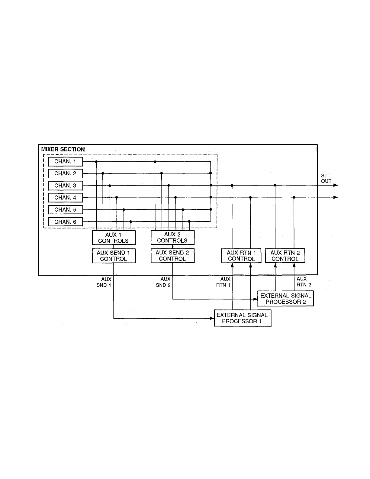
USING THE AUX SEND/RTN LOOPS
The MT3X’s AUX 1 and AUX 2 controls function like two secondary mixers that derive their input signals from the
main mixer’s six channels and combine them into mono signals which are delivered via the AUX SND 1 and AUX
SND 2 jacks (refer to the diagram below). You can use the AUX send controls to create two “effect mixes" which are
entirely independent of the main mix, thus applying the required degree of effect to each channel signal. One or both
of the AUX SND signals is sent to the input of an external signal processor (reverb, echo or other effect device), and
the output from the signal processor is returned to the corresponding AUX IN Jacks. The level of the signal received at
the AUX IN jacks can be adjusted using the AUX RTN control, and the resulting signal is combined with the MTSX’s
main stereo output signal.
Since the returned effect signal is combined with the mixer's stereo output signal, the AUX SND/RTN loops are most
ideally suited to adding effects to individual tracks during the final mixdown process.
MT3X
r NOTE:
Since the AUX SEND/RTN loops return the effect
signals to the mixer section’s stereo outputs, effects
can be added to channels during ping-pong record
ing as long as the panned channel-to-track assign
ment method is used. The AUX SEND/RTN loops
cannot be used to add effects when recording tracks
which have been assigned using the direct channelto-track assignment method.
------------------------------------------------------
-22 -
Page 24

PUNCH-IN/OUT RECORDING
Punch-in/out recording makes it possibie to re-record a short segment of an otherwise perfect track in order to correct
a mistake or “brush up” an important passage. You “punch-in" at the point where you begin recording the new
segment, and “punch-out” at the end of the new segment so that the previousiy-recorded materiai is not erased. The
MT3X AUTO PUNCH t/0 function makes this operation easier than ever.
• Manual Punch-in/out Using the REC SE
LECT Switches
1. Start the deck running — a few measures before
the section to be re-recorded begins — in the rec
ord-ready mode by pressing the REC button and
then the PLAY button with ali track REC SELECT
switches set to OFF. The red REC indicator wili
flash indicating that the transport is in the record-
ready mode. The PHONES SELECT switch should
be set to MIX so you can hear all the tracks and the
source you are about to record.
2. At a convenient break in the track switch the track
to be corrected to the record mode (punch-in by
switching the REC SELECT switch for that track to
the appropriate record position) and start playing
the new material to be recorded. The REC indicator
will light continuously as soon as the REC SELECT
switch is set to a record, position.
3. At the end of the re-recorded segment switch the
track back to the play mode (punch-out by switching
the REC SELECT switch for that track to OFF). The
red REC indicator will begin to flash.
• Footswitch Punch-in/out
1. Plug a YAMAHA FS-1 (optional) footswitch into the
MT3X PUNCH I/O jack.
2. Set the REC SELECT switch for the track to be
punched-in to the appropriate record position, and
press the REC button to activate the rec/pause
mode. The red REC indicator should flash instead
of lighting continuously. If the red REC indicator
lights continuously, press the footswitch once so
that it flashes.
3. Press the PLAY button to start the transport running
in the record-ready mode.
4. Press the footswitch to punch-in. The red REC indi
cator will light continuously.
5. Press the footswitch a second time to punch-out.
The red REC indicator will begin to flash.
TRACK 1
TRACK 2
TRACK 3
TRACK 4
All tracks monitored in PLAY
BACK mode (the deck is in the
REC mode, but the track REC
SELECT switches are set to
OFF).
Begin playback
it's a good idea to actually start playing a little
before the punch-in point.
STOP
The record mode is engaged for
track 3 only when the track 3
REC SELECT switch is set to
an ON position.
23
Page 25

Automatic Punch-in/out
This sophisticated MT3X function makes it possible to
pre-define the punch-in and punch-out points, so you
don’t have to touch the controls during the actual
punch-in/out operation.
1. Set the REC SELECT switch for the track to be
punched-in to the appropriate record position.
2. Use the AUTO PUNCH MEMO button to specify the
start and end (punch-in and punch-out) points for
the MTSX’s AUTO PUNCH I/O function. While run
ning the tape in the playback mode, press the
AUTO PUNCH MEMO button once to specify the
punch-in point (the AUTO PUNCH I/O “MEMO” indi
cator will flash), and then again to specify the
punch-out point (the AUTO PUNCH I/O “MEMO"
indicator will light continuously).
3. Rewind the tape to a point before the punch-in point
(refer to the electronic tape counter).
4. Press the AUTO PUNCH I/O button to activate the
automatic punch-in/out function. The AUTO PUNCH
I/O “I/O” indicator in the central display panel will
light, indicating that the AUTO PUNCH I/O function
is ready.
5. Press the REC and PLAY buttons to start the trans
port running in the AUTO PUNCH I/O mode. Prior
to the pre-defined punch-in point, the red REC indi
cator will flash. As soon as the punch-in point is
reached, the record mode will be activated and the
REC indicator will light continuously. When the
punch-out point is reached, the record mode will be
automatically disengaged.
r NOTE: -------------------------------------------
-----------
The AUTO PUNCH I/O mode can not be activated
when the tape is wound to a point beyond the pro
grammed punch-in point.
- NOTE: -----------------------------------------------------
The AUTO PUNCH I/O mode can be turned off by
pressing the AUTO PUNCH I/O button a second
time, and the MEMO display can be cleared by first
pressing the MEMO button, causing the “MEMO” in
dicator to flash, and pressing the “MEMO” button
again. The “MEMO” indicator will go out.
-24-
Page 26
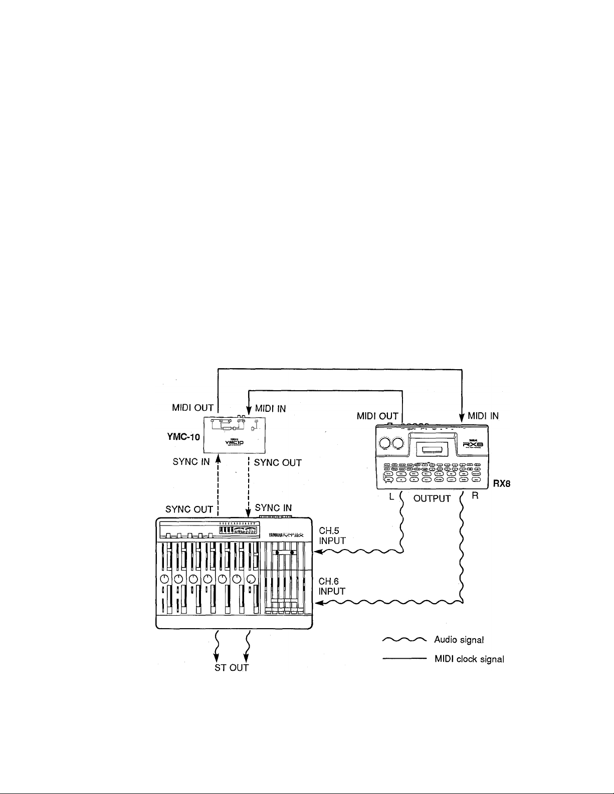
MIDI SYNC OPERATION
Using an external MIDI converter such a the YAMAHA YMC-10, it is possible to synchronize MIDI equipment such as
sequence recorders, digital rhythm programmers, MIDI computers and similar equipment to playback of material
recorded on the MT3X.
A simple MIDI sync system example is given below. In
this example, the YMC-10 MIDI Converter converts the
MIDI clock signal output from the RX8 Digital Rhythm
Programmer to an FSK (Frequency Shift-keyed) audio
signal that can be recorded on tape. And, in reverse,
the YMC-10 re-converts the FSK sync signal from the
tape back to a MIDI clock signal that can control the
RX8. Before any material is recorded on the tape, the
MT3X SYNC switch is turned ON, the rhythm pattern
programmed into the RX8 is played back, and the re
sultant sync signal from the YMC-10 is recorded onto
track 4 using normal recording procedure. Now, if the
RX8 is set to “EXTERNAL SYNC” (allowing it to be
controlled by external MIDI signals) and the tape is
played back, the RX8 will start, run, and stop in re
sponse to the sync track. Once this has been done, it is
possible to overdub and even ping-pong the remaining
three tracks on the tape, using the RX8 rhythm as a
reference. Since the sync track is controlling only the
speed and start/stop timing of the RX8, the rhythm pat
tern can be edited and re-programmed as required
without losing synchronization.
The same basic principles apply to synchronization of a
MIDI sequence recorder, MIDI computer or other
equipment. If a large number of external sources are
synchronized to tape, a small supplementary mixer
may be required to combine the source signals into a
stereo signal which can be returned to input channels 5
and 6 of the MT3X mixer.
MT3X
(TO SOUND SYSTEM)
FSK sync signal
25
Page 27
MAINTENANCE
The MT3X recording & playback head has been precision-constructed to extremely fine tolerances in order to make
high-quality 4-track recording possible. Optimum performance can only be achieved if the head surface is kept
immaculately clean. Cleaning should be carried out at regular intervals — at least after every 10 hours of use.
Dirty heads can cause any of, or a combination of, the following problems:
• Recording, playback and erasure are not possible.
• Reduced playback sound level.
• Fluctuating and or/distorted sound.
• Excessive noise.
• A drop in level at the high frequencies.
If any of the above problems occur, clean the heads carefull before assuming the fault is with the deck. Use a
commercially available head-cleaning kit (read the instructions provided with the kit), or wipe carefully with a cloth or
cotton swab that has been dampened with cleaning alchohol. Also clean the pinch roller at the same time as the
heads.
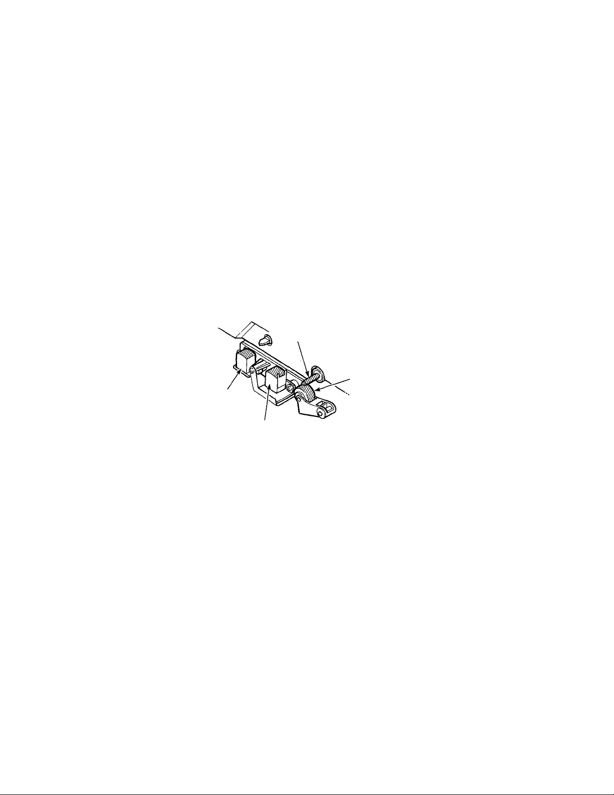
Capstan
Erase head
Record/playback head
Clean the Shaded Areas
Pinchroller
-26-
Page 28

SPECIFICATIONS
TAPE TRANSPORT
Tape Type
Heads
Tape Speed
Pitch Control
Wow & Flutter
Rewind Time
Motor
CONNECTORS
Input 1 & 2
Input 3-6
Aux Return 1 & 2 (L,R)
Stereo Out L & R
Phones Out
Monitor Out L & R
Tape Out 1 to 4
Aux Send 1 & 2
Chrome (70 microsec. EQ)
4-channel Permalloy rec/play head ,4-channel ferrite erase head
4.75 cm/sec., 9.5 cm/sec.
+ 10%
Less than 0.15% WRMS
Approx. 100 sec., for C-60 tape
DC servo motors (2)
Input Impedance 10 k-ohms
Rated Input Level
Max. Input Level
Min. Input Level
Input Impedance
Rated Input Level
Min. Input Level
Input Impedance
Rated Input Level
Min. Input Level
Output Impedance
Load Impedance
Rated Output Level
-10 dB to -50 dB (fader nominal)
+10 dB (gain control min.)
-56 dB (gain control, fader max.)
10 k-ohms
-10 dB (fader nominal)
-16 dB (fader max.)
10 k-ohms
-10 dB (fader nominal)
-16 dB (fader max.)
1 k-ohm
Greater than 10 k-ohms
-10 dB into 50 k-ohms
Load Impedance 8 to 40 ohms
Max. Output Level
Output Impedance
Load Impedance
Rated Output Level
Output Impedance
Load Impedance
Rated Output Level
Output Impedance
Load Impedance
Rated Output Level
100 mW + 100 mW/40 ohms
1 k-ohm
Greater than 10 k-ohms
-10 dB into 50 k-ohms
1 k-ohm
Greater than 10 k-ohms
-10 dB into 50 k-ohms
1 k-ohm
Greater than 10 k-ohms
-10 dB Into 50 k-ohms
ELECTRICAL SPECIFICATIONS
----------------------------------------
Frequency Response (NR OUT) 40 Rz to 18 kHz, ± 3 dB at 9.5 cm/sec.
40 Hz to 12.5 kHz, ± 3 dB at 4.75 cm/sec.
S/N ratio
Distortion
Channel Separation
Erasure Ratio
Noise Reduction
Equaiizer (shelving)
GENERAL
----------------
Power Requirements
Power Consumption
Dimensions (WxHxD)
Weight
’ dbx is a trademark of dbx Incorporated. OdB = 0.775 Vr.m.s.
85 dB, dbx ON, IHF-A
1.5%, 315 Hz (EIAJ)
Greater than 55 dB at 1 kHz
Greater than 70 dB at 1 kHz
dbx *
Max. ± 12 dB (HIGH: 10 kHz, LOW: 100 Hz)
U.S. <S Canadian Models: 120 V AC, 60 Hz
General Model: 220/240 VAC, 50/60 Hz
U.S. & Canadian Models: 24 W
General Model: 19 W
443 X 107 x 325 mm (17-7/16” x 4-3/16" x 12-13/16")
U.S. & Canadian Models: 3.7 kg (8 lbs. 2 oz)
General Model: 3.9 kg (8 lbs. 10 oz)
All specifications subject to change without notice.
-27 -
-------------
Page 29
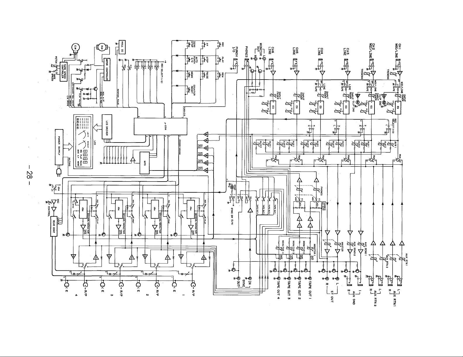
co
о
о
т;
о
>
Q
00
>
Page 30

IMPORTANT NOTICE FOR THE UNITED KINGDOM
Connecting the Plug and Cord
IMPORTANT. The wires in this mains lead are coloured in accordance with the follow
ing code:
BLUE : NEUTRAL
BROWN : LIVE
As the colours of the wires in the mains lead of this apparatus may not correspond with
the coloured markings identifying the terminals in your plug proceed as follows:
The wire which is coloured BLUE must be connected to the terminal which is marked
with the letter N or coloured BLACK.
The wire which is coloured BROWN must be connected to the terminal which is
marked with the letter L or coloured RED.
CANADA
THIS APPARATUS COMPLIES WITH THE "CLASS B" LIMITS FOR RADIO
NOISE EMISSIONS SET OUT IN RADIO INTERFERENCE REGULATIONS.
CET APPAREIL EST CONFORME AUX NORMES "CLASS В", POUR BRUITS
RADIOELECTRIQUES. TEL QUE SPÉCIFIÉ DANS LE REGLEMENT SUR LE
BROUILLAGE RADIOELECTRIQUE.
Page 31

ENREGISTREUR DE CASSETTE MULTIPISTE
l!\/îinr
MANUEL D'INSTRUCTIONS
Page 32

FELICITATIONS!
Votre enregistreur de cassette multipiste MT3X est un outil créatif peu commun qui vous permettra de travailler avec
le son de nombreuses manières différentes. Que vous ayez besoin d'enregistrer des instruments acoustiques et des voix
au moyen de microphones, ou des instruments électroniques et autres sources directement connectés, ou encore un
mélange créatif des deux, le MT3X vous permet de créer votre propre son sans problème et avec la plus grande
aisance. Vous pouvez tout simplement enregistrer et remélanger quatre pistes, ou utiliser la technique de
Venregistrement multipiste en “ping-pong" pour enregistrer individuellement jusqu’à dix parties indépendantes,
ajoutant le son couche par couche jusqu’à ce que vous ayez créé l’arrangement et la texture que votre imagination
demande. Il y a même une fonction sophistiquée dite de “punch-in!punch-out" qui vous permet de réenregistrer un
segment d’une piste déjà enregistrée d’une manière quasiment automatique. Le MT3X est aussi simple à utiliser seul
qu’avec un groupe. Et parce que c’est un YAMAHA, vous avez la certitude que le MT3X vous donnera la qualité
sonore et les performances générales les meilleures qu’il soit possible d’obtenir.
Afin d’utiliser au mieux les innombrables fonctions du MT3X et d’en obtenir des performances maximales, nous vous
conseillons vivement de lire très attentivement ce manuel d’instructions et de le comserver en lieu sûr afin de pouvoir
vous y reporter ultérieurement si besoin est.
TABLES DES MATIERES
PRECAUTIONS ........................................................................................................... 32
AVANT UTILISATION .....................................................................................................33
COMMANDES ET CONNECTEURS ............................................................................ 35
EXEMPLE DE RACCORDEMENT..................................................................................43
METHODE D’ENREGISTREMENT
ENREGISTREMENT DE LA PREMIERE PISTE.............................................................45
ETAPE 1 : ASSIGNATION CANAL/PISTE...................................................... 45
ETAPE 2; PREPARATION DU SYSTEME D’ECOUTE DE CONTROLE ... .46
ETAPE 3: REGLAGE DES NIVEAUX D’ENREGISTREMENT
ETAPE 4: ENREGISTREMENT .........................................................................47
SURMIXAGE....................................................................................................................48
ENREGISTREMENT EN PING-PONG............................................................................49
EXEMPLE D’UN ENREGISTREMENT EN PING-PONG ..................................50
MIXDOWN
UTILISATION DES BOUCLES DE TRANSMISSION/RETOUR.....................................53
ENREGISTREMENT PUNCH-IN/PUNCH-OUT...............................................................54
UTILISATION SYNCHRONISEE MIDI.............................................................................56
ENTRETIEN ................................................................................................................... 57
SPECIFICATIONS .......................................................................................................... 58
SCHEMA DE PRINCIPE ............................................................................................... .59
..........
............................................................................................................ 51
Punch-in/Punch-out manuel en utilisant les sélecteurs REC SELECT
Punch-in/Punch-out par pédale..................................................................... 54
Punch-in/Punch-out automatique....................................................................55
................................................................................
.........................
......
44
47
54
-31 -
Page 33

PRECAUTIONS
1. EVITER CHALEUR, HUMIDITE, POUSSIERE
ET VIBRATIONS EXCESSIVES
Ne pas placer l’appareil là où il pourrait être soumis
à des températures ou à une humidité excessives,
comme par exemple à proximité d’un radiateur, d’un
calorifère, etc. Eviter également les endroits
particulièrement poussiéreux ou soumis à des vibra
tions qui pourraient provoquer des dommages
2. EVITER LES CHOCS
Des chocs physiques violents peuvent endommager
l’appareil. Par conséquent le manipuler avec soin.
3. NE PAS OUVRIR L’APPAREIL ET NE PAS
ESSAYER DE LE REPARER OU DE LE
MODIFIER SOI-MEME
Ce produit ne contient pas de pièces réparables par
l’utilisateur. Pour l’entretien et les réparations,
toujours contacter un réparateur YAMAHA qualifié.
Le fait d’ouvrir l’appareil et/ou d’altérer les circuits
internes annulerait la garantie.
4. AVANT DE PROCEDER AUX CONNEXIONS
OU AUX DEBRANCHEMENTS, CONFIRMER
QUE L’APPAREIL EST HORS TENSION
Avant de brancher ou de débrancher les cordons
toujours mettre l’appareil hors tension. Cette
démarche est importante, car elle permet d’éviter
tout dommage à l’appareil, ainsi qu’aux autres com
posants raccordés.
5. MANIPULER PRECAUTIONNEUSEMENT
LES CORDONS
Brancher et débrancher les cordons, le cordon
d’alimentation secteur y compris, en saisissant le
connecteur, jamais en tirant sur le cordon.
6. NETTOYER L’APPAREIL AVEC UN CHIF
FON DOUX ET SEC
Ne jamais utiliser de solvants, tels que de la benzine
ou un dissolvant, pour nettoyer l’appareil. L’essuyer
simplement avec un chiffon doux et sec.
7. TOUJOURS UTILISER UNE SOURCE
D’ALIMENTATION QUI CONVIENNE
Les spécifications d’alimentation du MT3X sont
celles de la région d’achat (la tension et la consom
mation d’électricité sont indiquées sur le panneau
inférieur). Si l’appareil doit être utilisé dans une
autre région où la tension risque d’être différente,
consulter un distributeur YAMAHA avant de réutiliser
le MT3X.
8. MAINTENIR LES TETES ET LE PASSAGE
DE LA BANDE PROPRES
Afin de toujours obtenir des performances élevées et
une bonne qualité sonore du MT3X, il est très impor
tant de nettoyer régulièrement les têtes et le pas
sage de la bande (idéalement parlant avant chaque
séance d’enregistrement). Pour ce faire, utiliser un
kit de nettoyage spécialement conçu pour être utilisé
avec des appareils à cassette.
9. N’UTILISER QUE DES CASSETTES AU
CHROME DE QUALITE SUPERIEURE
Le MT3X a été conçu pour être utilisé avec des
cassettes CrOz (chrome) et ses performances se
ront moindre avec un autre type de cassette.
Toujours choisir des cassettes d’une marque de
confiance.
-32-
Page 34

AVANT UTILISATION
■ DIFFERENCE ENTRE PISTES ET CANAUX
Il arrive souvent que l’on confonde le terme “piste” et le terme “canal”. Afin d’utiliser correctement cet appareil, il est
nécessaire de comprendre la signification de ces deux termes.
PISTE:
Désigne les parties de la bande elle-même où les
signaux sont enregistrés. La bande d’une cassette
comprend 4 pistes, ce qui permet d’enregistrer quatre
signaux différents. Pour un enregistrement convention
CANAL:
Le trajet d’un signal d’entrée ou de sortie. Côté entrée,
l’appareil comprend six canaux INPUT et deux canaux
AUX. Le côté sortie comprend un canal stéréo (con
stitué de deux canaux mono) et un canal AUX.
nel deux pistes (stéréo gauche et droite) sont utilisées
sur chaque face (sens de défilement de la bande) de la
cassette.
■ QU'EST-CE QU'UN ENREGISTREUR DE CASSETTE MULTIPISTE7
La différence existant entre l’enregistreur de cassette multipiste MT3X et un magnétocassette conventionnel est
indiquée ci-après.
MAGNETOCASSETTE CONVENTIONNEL
ENREGISTREUR DE CASSETTE MULTIPISTE MT3X
Pour la piste de canal droit
Pour la piste de canai gauche
Pour ia piste de canai gauche
sur la face B
Pour la piste de canal droit
sur la face B
Pour la piste de canal droit
sur la face A
Pour la piste de canal gauche
sur la face A
Pour le canal 4
Pour le canal 3
Pour le canal 2
Pour le canal 1
Piste pour ie canal 4 (piste 4)
Piste pour le canal 3 (piste 3)
Piste pour le canal 2 (piste 2)
Piste pour ie canai 1 (piste 1)
Le schéma illustre la manière dont un magnétocassette
stéréo conventionnel enregistre et reproduit le son.
Les quatre pistes sont utilisées pour le son gauche et
le son droit (en stéréo) de chaque face de la bande. Le
MT3X utilise ces quatre pistes pour l’enregistrement/
lecture unidirectionnel sur une seule face de la bande.
Les magnétocassettes conventionnels enregistrent et
reproduisent toujours le son dans le même mode, la
face de la bande (ou sens de défilement) déterminant
les deux pistes qui seront utilisées. Ces appareils ne
permettent pas la sélection des pistes, ni pour
l’enregistrement, ni pour la lecture.
Les enregistreurs multipistes permettent, quant à eux,
d’enregistrer ou de reproduire séparément les pistes
sélectionnées. Ceci permet d’avoir une certaine sou
plesse d’enregistrement et de lecture impossible avec
les magnétocassettes conventionnels.
-33 -
Page 35

■ A PROPOS DES CASSETTES
Cet appareil a été conçu pour être utilisé uniquement avec des bandes au chrome et il ne fonctionnera pas correcte
ment avec des bandes de type ferrochrome. Des bandes Cr02 (Polarisation: ELEVEE; EQ: 70 |is) doivent être
utilisées. En outre, l'utilisation de bandes C-120 n’est pas conseillée du fait que ces bandes ont des performances
médiocres et qu’elles risquent de provoquer des pannes de l’appareil.
• Prévention contre l’effacement accidentel d’un
enregistrement
Pour prévenir tout effacement accidentel d’enregistre
ments précieux, toutes les cassettes sont pourvues de
languettes de protection situées sur leur bord supé
rieur. Lorsqu’une de ces languettes est cassée, à
l’aide d’un tournevis ou de tout autre outil approprié, il
est impossible d’enregistrer sur la face correspondante
de la bande. Ceci empêche tout effacement accidentel
d’un enregistrement. Dans le cas d’un enregistrement
à 4 pistes, il est nécessaire de casser les languettes de
protection de la face A et de la face B de la bande.
Pour enregistrer sur une cassette dont les languettes
de protection ont été cassées, recouvrir l’orifice (à la
place des languettes) avec un morceau de ruban
adhésif.
PREVENTION CONTRE L’EFFACEMENT ACCIDENTEL
D’UNE BANDE
Casser la languette à
l’aide d'un tournevis ou
outil similairesimilar im-
Languette de
la face B
plenent.
• Reprise du mou d’une bande
Si une bande est utilisée alors qu’elle présente du mou,
ou qu’un morceau de la bande est sorti de la cassette,
la bande risque de s’enrouler autour du cabestan ou du
galet-presseur. Afin d’empêcher cela, introduire un
crayon ou un stylo à bille dans le centre d’une des
bobines et le tourner pour reprendre le mou de la
bande.
Cassette shell
• Rangement des cassettes
Pour empêcher que la bande prenne du mou, mettre
un dispositif d’arrêt ou ranger les cassettes dans leurs
boîtes. Ne pas ranger les cassettes en plein soleil, ou
dans des endroits soumis à une humidité ou des à
températures excessives, car cela pourrait endom
mager la bande. Conserver également les bandes loin
de toutes sources de champ magnétique, telles que
récepteur de télévision, enceintes acoustiques, car les
enregistrements pourraient être effacés ou quelque
peu altérés.
ENREGISTREMENT SUR UNE CASSETTE DONT LES
LANGUETTES ONT ETE CASSEES
Recouvrir d’un morceau de
-34-
Page 36

COMMANDES ET CONNECTEURS
PANNEAU DE COMMANDE —
FACE AVANT —
-35-
Page 37

CANAUX ET PISTES
Le terme “canal” et le terme “piste” sont utilisés dans ce manuel d’instructions pour
différencier les six “canaux” de l’étage mélangeur et les quatre “pistes” de l’étage enre
gistreur du MT3X. Le terme “piste” est également employé pour désigner les quatre
“pistes” effectivement enregistrées sur la bande.
CANAUX D'ENTREE DE L'ETAGE MELANGEUR
O Bornes d’entrée 1 à 6
Ces six bornes d’entrée (MIC/LINE 1, MiC/LINE 2
et LINE 3 à LINE 6) acceptent des signaux en
provenance de n’importe quelles sources de ni
veau de ligne, comme par exempie un instrument
de musique électronique ou un lecteur de cassette.
Les prises MIC/LINE 1 et 2 acceptent également
des signaux en provenance d’instruments de mu
sique électriques tels que guitares et basses, ou en
provenance de microphones. Les entrées 1 à 6
sont des prises jacks mono standard de 1/4".
Lorsqu’une source est connectée à une de ces
prises, ses signaux sont transmis au canal cor
respondant de l’étage mélangeur du MT3X.
Q Commandes d’équilibre (MIC/LINE)
(Canaux 1 et 2 uniquement)
Les commandes d’équilibre permettent de régler la
sensibilité des entrées du canal 1 et du canal 2 afin
qu’elles puissent accepter des signaux ayant des
niveaux très variés, allant du niveau de ligne au
niveau de microphone. Les commandes
d’équilibre sont utilisées conjointement aux
atténuateurs du canal 1 et du canal 2 afin d’obtenir
le niveau d’enregistrement optimal pour une
grande variété de sources (voir “REGLAGE DES
NIVEAUX D’ENREGISTREMENT” à la page 47).
e Sélecteurs TAPE-OFF-MIC/LINE (TAPE-
OFF-LJNE) (Canaux 1 à 4 uniquement)
Ces sélecteurs déterminent si l’entrée du canal
correspondant de l’étage mélangeur sera, soit la
sortie de ia piste ayant le numéro correspondant de
l’étage enregistreur du MT3X, soit l’entrée MIC/
LINE ou LINE. A la position OFF, l’entrée du canal
correspondant est coupée. Les canaux 5 et 6
n’acceptent que des entrées de niveau de ligne.
O Commandes d’égalisation (LO et HI)
Ces commandes permettent de modifier indivi
duellement la réponse en fréquence de chaque
canal. Les commandes HI et LO fonctionnent de la
manière suivante:
Commande Plage
HI ±12 dB 10 kHz Coupure
LO ±12 dB 100 Hz
0
Commandes AUX 1 et AUX 2
Les commandes AUX servent principalement lors
de l’addition d’effets, tels que les effets de
réverbération ou de retard, au son de chaque canal
ou piste. Les commandes AUX 1 et AUX 2 de
chaque canal de l’étage mélangeur déterminent la
partie du signal de ce canal qui sera transmises à
la prise AUX SND 1 ou à la prise AUX SND 2. Les
prises AUX SND peuvent être reliée à l’entrée d’un
processeur de signaux externe, comme par exem
ple le processeur d’effets multiples professionnel
YAMAHA SPX9G0 (voir “UTILISATION DES
BOUCLES DE TRANSMISSION/RETOUR” à la
page 53).
Fréq. Type
Coupure
36
Page 38

0 Commandes panoramiques (PAN)
Les commandes PAN assignent le signal en prove
nance du canal correspondant de l’étage
mélangeur à la position souhaitée dans le “champ
sonore stéréo”. Si une commande PAN est
tournée à fond sur la position “LEFT” (gauche), le
signal de ce canal rie sera appliqué qu’à la sortie
de canal gauche (ST OUT L) du MT3X. Si une
commande PAN est tournée à fond sur la position
“RIGHT” (droite), le signal ne sera appliqué qu’à la
sortie ST OUT R. Si une commande PAN est mise
sur la position centrale, le signal de ce canal sera
appliqué d’une manière égale aux sorties de canal
gauche et de canal droit et le son apparaîtra au
centre du champ sonore stéréo (en un point à
égale distance des deux enceintes acoustiques).
Les autres réglages des commandes PAN placent
le son sur une position correspondant approxima
tivement à la position des commandes PAN, et ce
en variant le niveau du signal transmis aux sorties
de canal gauche et de canal droit.
Les commandes PAN peuvent également être
utilisées pendant l’enregistrement pour assigner les
signaux en provenance de plusieurs canaux à une
seule piste de l’étage enregistreur, ou pour as
signer un canal à une piste de l’étage enregistreur
ayant un numéro différent (voir ‘ASSIGNATION
CANAL/PISTE” à la page 45).
réaliser l’équilibre (mélange) du son des pistes de
l’étage enregistreur lors de la reproduction d’un
enregistrement.
0 Sélecteurs d’enregistrement
(REC SELECT)
Les sélecteurs REC SELECT sont utilisés pendant
l’enregistrement pour assigner (transmettre) les
signaux en provenance de chaque canal de l’étage
mélangeur, soit directement à la piste correspon
dante de l’étage enregistreur, soit à une piste
différente via les commandes PAN (voir “ASSIG
NATION CANAL/PISTE” à la page 45).
- REMARQUE: --------------------------------------------
Lorsqu’un des sélecteurs REC SELECT est mis sur
une position autre que “OFF”, l’indicateur rouge “•
REC” situé au-dessous de l’indicateur de niveau à
barres du canal correspondant (voir “PANNEAU
D’AFFICHAGE CENTRAL à la page 41) se met à
clignoter pour indiquer que le MT3X est prêt pour
l’enregistrement.
0 Touche de synchronisation (SYNC)
Lorsque la touche SYNC est activée (l’indicateur
SYNC s’allume), l’entrée et la sortie de la piste 4
de l’étage enregistreur du MT3X sont dirigées vers
les prises SYNC IN et OUT de la face arrière. Les
prises SYNC IN et OUT peuvent être connectées à
l’entrée et à la sortie correspondantes d’un conver
tisseur MIDI externe tel que le YAMAHA YMC-10,
ce qui permet la synchronisation d’enregistreurs de
séquence, de programmeurs de rythmes,
d’ordinateurs ou autres appareils MIDI similaires,
sur la reproduction du MT3X.
O Atténuateurs de canal
Les atténuateurs de canal permettent de régler le
niveau (volume) du signal du canal correspondant
de l’étage mélangeur, que ce signal provienne
d’une source connectée à une prise d’entrée ou
qu’elle provienne de l’étage enregistreur du MT3X.
Les atténuateurs sont utilisés pour obtenir le ni
veau optimal lors de l’enregistrement et pour
-37
Page 39

ETAGE MELANGEUR PRINCIPAL
COMMANDES ET CONNECTEURS
<E> Commandes de transmission auxiiiaire
(AUX SEND 1 et AUX SEND 2)
Ces commandes permettent de régler le niveau de
sortie d’ensemble des mélanges AUX 1 et AUX 2
produits en utilisant les commandes AUX de canal
correspondantes. AUX SEND 1 règle le niveau
d’ensemble des signaux du mélange AUX 1
appliqués à la prise AUX SND 1, alors que AUX
SEND 2 règle le niveau d’ensemble des signaux du
mélange AUX 2 appliqués à la prise AUX SND 2.
Ces commandes doivent être utilisées pour assurer
un équilibre optimal entre le niveau de sortie AUX
SND de l’étage mélangeur et la sensibilité d’entrée
du processeur de signaux externe utilisé.
<D Commandes de retour auxiliaire
(AUX RTN 1 et AUX RTN 2)
Les commandes AUX RTN 1 et AUX RTN 2
déterminent le niveau auquel le signal en prove
nance d’un processeur de signaux externe trans
mis par la prise AUX SND sera renvoyé et mélangé
au signal de sortie stéréo principal du MT3X. La
sortie du processeur de signaux externe transmise
par la prise AUX SND 1 ou AUX SND 2 doit être
connectée aux prises AUX RTN 1 (R/L) ou AUX
RTN 2 (R/L) (voir “UTiLISATION DES BOUCLES
DE TRANSMiSSION/RETOUR” à la page 53).
® Commandes d’écoute de contrôle
(MONITOR)
Chacune des quatre commandes MONITOR
détermine le niveau du signal de la piste corres
pondante de l’étage enregistreur qui est transmis à
la prise PHONES lorsque le sélecteur PHONES
SELECT est sur la position “MONITOR” ou “MIX”.
Les commandes MONITOR servent principalement
à régler les niveaux optima pour l’écoute de
contrôle des pistes enregistrées pendant
l’enregistrement de nouveaux matériaux (sur
mixage).
® Sélecteur de casque d’écoute
(PHONES SELECT)
Le MT3X permet l’écoute de contrôle, via un
casque stéréo connecté à la prise PHONES. Le
sélecteur PHONES SELECT détermine quels
signaux seront transmis à la prise PHONES pour
être contrôlés.
MONITOR: Dans cette position seule la sortie des
quatre pistes de l’étage enregistreur est trans
mise directement à la prise PHONES via les
quatre commandes MONITOR.
MIX: La sortie des quatre pistes de l’étage enregis
treur (via les commandes MONITOR) et la
sortie stéréo de l’étage mélangeur sont trans
mises à la prise PHONES.
STEREO: Seule la sortie stéréo de l’étage
mélangeur est transmise à la prise PHONES.
<D Commande de casque d’écoute (PHONES)
La commande PHONES règle à la fois le niveau du
signal de casque d’écoute capté à la prise
PHONES et le niveau du signal appliqué à la prise
MONITOR OUT située sur le panneau arrière, per
mettant ainsi d’obtenir facilement le niveau
d’écoute de contrôle le plus confortable.
® Prise de casque d’écoute (PHONES)
Un casque d’écoute de contrôle, ayant une
impédance comprise entre 8 et 40 ohms environ,
peut être connecté à cette prise. L’écoute de
contrôle par casque est le moyen le plus pratique
d’écouter les divers signaux du MT3X, et dans ce
but nous préconisons vivement l’achat d’un casque
d’écoute de contrôle de bonne qualité. Les
casques d’écoute de contrôle YAMAHA de la série
RH sont Idéals.
® Atténuateur principal (MASTER)
L’atténuateur MASTER permet de régler le niveau
de sortie d’ensemble de l’étage mélangeur du
MT3X et, par conséquent, le niveau du signal de
sortie appliqué aux prises ST OUT. L’atténuateur
MASTER règle également le niveau
d’enregistrement lorsque des canaux de l’étage
mélangeur ont été assignés aux pistes de l’étage
enregistreur, via les commandes PAN (voir
“REGLAGE DES NiVEAUX D’ENREGISTRE
MENT” à la page 47).
-38
Page 40

ETAGE ENREGISTREUR MULTIPLISTE
® Interrupteur dbx (ON/OFF)
L’interrupteur dbx commande l’activation/
désactivation du circuit interne de réduction du
bruit dbx du MT3X. Pendant ia lecture ou l’en
registrement normal à l’aide du MT3X, l’interrupteur
dbx doit être mis sur “ON”. Ceci permet d’obtenir
un rapport signal/bruit considérablement amélioré
(jusqu’à 85 dB) de sorte que les enregistrements
seront plus clairs, avec très peu de sifflement de
bande. Pour que le système de réduction de bruit
dbx soit efficace, il doit être activé aussi bien pen
dant l’enregistrement et que pendant la lecture.
L’interrupteur dbx peut être mis sur “OFF” pendant
la lecture de bandes enregistrées sur un autre
appareil et non codées dbx.
® Sélecteur de vitesse de défilement
(TAPE SPEED)
Le sélecteur TAPE SPEED permet de sélectionner
soit la vitesse de défilement standard de 4,75 cm/
sec, soit la vitesse spéciale du MT3X de 9,5 cm/
sec. Utiliser la vitesse de défilement standard
(4,75) pour la lecture de bandes enregistrées sur
magnétocassettes standards ou pour des raisons
d’économie de bande. Utiliser la vitesse élevée
(9,5) pour obtenir une meilleure qualité sonore.
L’amélioration de la qualité sonore que donne la
vitesse de défilement élevée est importante et nous
préconisons d’utiliser cette vitesse pour tous les
enregistrements importants.
<E> Commande de réglage de la vitesse de
défilement (PITCH)
La commande PITCH fait varier la vitesse de
défilement de la bande de ±10%, ce qui permet
“d’accorder” les matériaux enregistrés avec le
MT3X sur la hauteur tonale d’instruments de mu
sique, ou de légèrement prolonger ou réduire le
temps de passage d’un enregistrement pour des
raisons de synchronisation. La vitesse de
défilement est normale lorsque la commande
PITCH est à la position centrale marquée par un
déclic. Pour accélérer la vitesse de défilement
faire coulisser la commande vers l’extrémité “-i-” de
l’échelle et pour la réduire la faire coulisser vers
l’extrémité
® Commande d’arrêt sur zéro (ZERO STOP)
La commande ZERO STOP permet de retrouver_
rapidement un point spécifique d’une bande. Cette
fonction est particulièrement pratique dans le cas
d’un enregistrement multipiste du fait qu’il est
nécessaire de rembobiner constamment la bande
jusqu’au même point pour surmixer (à savoir; en
registrer une nouvelle piste tout en écoutant les
pistes précédemment enregistrées). Pour utiliser
la fonction ZERO STOP, mettre le compteur de
bande (voir plus loin) à “0000” au point qui doit être
retrouvé en appuyant sur la touche COUNTER
RESET. Ensuite, la commande ZERO STOP étant
mise sur “ON” (l’indicateur ZERO STOP ‘ON” du
panneau d’affichage central s’allume), la bande
s’arrêtera automatiquement lorsque le compteur
atteint “0000” en modes de rembobinage ou
d’avance rapide.
Touche AUTO PUNCH I/o
Cette touche permet d’activer la fonction
d’enregistrement punch-in/punch-out automatique
du MT3X, faisant ainsi du réenregistrement de
n’importe quels segment d’une piste
précédemment enregistrée une opération très
simple. Lorsque la touche AUTO PUNCH I/O est
enfoncée — après avoir spécifié le point de punch-
in et le point de punch-out à l’aide de la touche
AUTO PUNCH MEMO (voir ci-après) — l’indicateur
AUTO PUNCH I/O “I/O” du panneau d’affichage
central s’allume pour indiquer que la fonction
AUTO PUNCH I/O est activée. Si le mode
d’enregistrement est alors déclenché de la manière
normale, l’appareil ne se mettra effectivement en
mode d’enregistrement que pour la partie spécifiée
de la ou des pistes sélectionnées qui sera alors
enregistrée automatiquement. Pour plus de
détails, voir “enregistrement punch-in/punch-out
automatique” à la page 55.
Touche AUTO PUNCH MEMO
Cette touche est utilisée pour spécifier le point de
début et le point de fin (point punch-in et point
punch-out) d’activation de la fonction AUTO
PUNCH I/O du MT3X. Tout en faisant défiler la
bande en mode de lecture, appuyer une première
fois sur la touche AUTO PUNCH MEMO pour
spécifier le point punch-in (l’indicateur AUTO
PUNCH I/O “MEMO” se met à clignoter) et une
deuxième fois pour spécifier le point punch-out
(l’indicateur AUTO PUNCH I/O “MEMO” reste alors
allumé de manière continue). Pour plus de détails.
Page 41

COMMANDES ET CONNECTEURS
voir “enregistrement punch-in/punch-out automa
tique” à la page 55.
Touche de remise à zéro
(COUNTER RESET)
La touohe COUNTER RESET permet de remettre
le compteur de bande électronique à “0000” sur la
position à laquelie se trouve la bande.
I Commandes de défilement
Ces commandes électroniques à effieurement per
mettent un contrôie sûr et régulier de toutes les
fonctions de défilement de la bande.
Lecture (PLAY): Lance le défilement de la bande
en mode de lecture. L’indicateur vert PLAY
du panneau d’affichage central reste allumé
pendant la lecture.
Enregistrement (REC): Appuyer sur la touche
REC pour passer au mode “REC/PAUSE”. Si
tous les sélecteurs REC SELECT sont sur la
position “OFF”, l’indicateur rouge REC cli
gnote, aiors que i’indicateur vert PAUSE reste
aiiumé continuellement. Si un des sélecteurs
REC SELECT est mis sur une position autre
que “OFF”, l’indicateur rouge REC et
i’indicateur vert PAUSE s’ailument tous les
deux continuellement. Dans ce mode la
bande ne défile pas et l’enregistrement n’a
pas encore commencé. Lorsque l’appareil
est en mode REC/PAUSE, appuyer sur la
touche PLAY pour lancer effectivement le
défilement de la bande en mode enregistre
ment (si un des sélecteurs REC SELECT est
mis sur une position autre que “OFF”), ou en
mode prêt à l’enregistrement (si tous les
sélecteurs REC SELECT sont mis sur la posi
tion “OFF”). L’indicateur rouge REC et
l’indicateur vert PLAY restent ailumés pen
dant l’enregistrement. L’indicateur rouge
REC continuera de clignoter et l’enregistre
ment ne se fera pas si aucun des sélecteurs
REC SELECT n’est sur une position
d’enregistrement.
r REMARQUE: ---------------------------------------------
Le mode d’enregistrement ne peut pas être activé si
les languettes de protection de ia cassette mise en
place ont été enlevées.
PAUSE: Interrompt la lecture ou l’enregistrement.
L’indicateur vert PAUSE s’allume en mode de
PAUSE. Appuyer sur la touche PLAY pour
sortir du mode de PAUSE et reprendre la lec
ture ou l’enregistrement.
Rembobinage (REW) et Avance rapide (FF): Ces
touches iancent le défilement rapide de la
bande dans le sens correspondant.
Arrêt (STOP): Arrête immédiatement le défilement
de la bande quel que soit le mode de fonc
tionnement.
Compartiment de cassette
La cassette est mise en place dans ce compar
timent. Utiiiser uniquement des cassettes au
chrome (Cr02) de quaiité supérieure. Tout autre
type de cassette ne permettra pas d’obtenir des
caractéristiques de fréquence correctes et un bruit
minimal avec le MT3X. Soulever tout d’abord le
volet du compartiment (une ianguette se trouve sur
le côté droit du volet), introduire ensuite la cassette
avec son bord ouvert (le côté où la bande est vi
sible) dirigé vers les commandes de défilement.
Pousser le bord arrière (fermé) de la cassette pour
le mettre sous le doigt de retenue central à l’arrière
du compartiment et pousser ensuite le bord avant
(ouvert) dans le mécanisme, SANS FORCER!
Refermer ensuite le volet du compartiment.
- REMARQUE:
Du fait que le MT3X utilise toute la largeur de la
bande pour enregistrer quatre pistes, la cassette ne
peut être enregistrée que sur une seule face. Si on
tente de tourner la cassette et d’enregistrer sur
l’autre face, tout l’enregistrement déjà effectué sera
effacé.
--------------------------------------------
r REMARQUE: ---------------------------------------------
Seules les pistes dont ie séiecteur REC SELECT
correspondant est mis sur une position
d’enregistrement seront enregistrées lorsque le
mode d’enregistrement est activé.
Prise de pédale (PUNCH I/O)
Une pédale YAMAHA FS-1 en option peut être
connectée à cette prise afin de pouvoir commander
au pied l’enregistrement punch-in/punch-out (voir
“ENREGISTREMENT PUNCH-IN/PUNCH-OUT à
la page 54).
40
Page 42

PANNEAU D'AFFICHAGE CENTRAL
Indicateurs de niveau des pistes d’enregistrement
Ces quatre indicateurs à barres verticaux, du type
indicarteur de crête, affichent d’une manière
précise ies niveaux de sortie des quatre pistes de
i’étage enregistreur. Les indicateurs de niveau des
pistes jouent un rôle important lors du réglage des
niveaux d’enregistrement optima pour
l’enregistrement de matériaux nouveaux (voir
“REGLAGE DES NIVEAUX D’ENREGISTRE
MENT” à la page 47).
Indicateurs de niveau principaux
{LEFT et RIGHT)
Les indicateurs de niveau horizontaux LEFT et
RIGHT affichent le niveau du bus principal stéréo
du MT3X, ce qui permet d’avoir une indication
visuelle précise du niveau d’ensemble du signal de
programme.
® Compteur de bande électronique
Le compteur de bande électronique à quatre
chiffres du MT3X permet de repérer facilement la
position de la bande. Il est conseillé de noter les
indications du compteur pour tous les points impor
tants d’un enregistrement afin de pouvoir les
retrouver facilement plus tard.
® Indicateurs de mode
Les indicateurs “• REC” situés sous les indicateurs
de niveau à barres verticaux indiquent les pistes
prêtes à l’enregistrement, les indicateurs "REC”,
“PLAY” et “PAUSE” indiquent le mode de
défilement de la bande, l’indicateur ZERO STOP
“ON” permet de savoir si la fonction ZERO STOP a
été activée, alors que les indicateurs AUTO
PUNCH I/O “I/O” et “MEMO” indiquent l’état de la
fonction AUTO PUNCH I/O.
-41
Page 43

PANNEAU ARRIERE
COMMANDES ET CONNECTEURS
Prise de sortie de bande (TAPE OUT)
Les quatre prises TAPE OUT sont les sorties di
rectes des pistes correspondantes de l’étage en
registreur du MT3X. Ces prises permettent de
transmettre la sortie des quatre pistes de l’étage
enregistreur à une table de mixage externe. Les
prises TAPE OUT peuvent également être utilisées
pour transmettre chaque piste de l’étage enregis
treur à des processeurs de signaux externes, dont
les sorties peuvent être ensuite retournées aux
entrées de l’étage mélangeur du MT3X.
Les prises TAPE OUT sont des prises à broches
RCA ayant un niveau de sortie nominal de -10 dB
sous une charge supérieure à 50 kohms.
Prises de sortie stéréo (ST OUT R et L)
Ces prises sont les sorties principales du MT3X;
elles fournissent les signaux de sortie stéréo en
provenance de l’étage mélangeur du MT3X. Les
prises ST OUT peuvent être connectées à un
système de sonorisation stéréo, pour le monitoring
ou l’écoute, ou à un deuxième enregistreur de cas
sette pour l’enregistrement d’un “mixage” stéréo
d’une bande maîtresse multipiste du MT3X. Les
prises ST OUT R et L sont des prises à broches
RCA ayant un niveau de sortie nominal de -10 dB
sous une charge supérieure à 50 kohms.
-42-
Prises d’entrée et de sortie de synchro
nisation (SYNC IN et OUT)
Ces prises peuvent être connectées aux entrées et
sorties correspondantes d’un convertisseur MIDI
externe, comme par exemple le YAMAHA YMC-10,
ce qui permet l’enregistrement d’un signal FSK de
symchronisation sur la piste 4 de l’étage enregis
treur du MT3X (l’interrupteur SYNC du MT3X doit
être enclenché). Le signal de synchronisation en
registré peut être utilisé pour synchroniser des en
registreurs de séquence, programmeurs de ryth
mes, ordinateurs ou autres appareils MIDI simi
laires, sur la reproduction du MT3X.
Prises de transmission et de retour
(AUX SND et RTN)
Les prises AUX SND (1 et 2) et AUX RTN (1 et 2)
facilitent l’utilisation d’un processeur de signaux
externe (comme par exemple le processeur d’effets
multiples professionnel YAMAHA SPX900) afin
d’ajouter des effets aux signaux du MT3X. La prise
AUX SEND 1 ou 2 doit être connectée à l’entrée du
processeur de signaux et la sortie du processeur
de signaux aux prises AUX RTN correspondantes.
Des prises stéréo sont prévues pour AUX RTN 1 et
2, ce qui assure la compatibilité avec une grande
variété de processeurs de signaux à hautes per
formances du type à entrée mono/sorlie stéréo que
l’on trouve actuellement sur le marché.
Page 44

Le fait d’avoir deux boucles AUX SEND/RTN as
sure une plus grande souplesse de traitement des
signaux, (voir ‘‘UTILISATION DES BOUCLES DE
TRANSMISSION/RETOUR” à la page 53).
Prises de sortie d’écoute de contrôie (MONITOR OUT L et R)
Ces prises sortent la version niveau de ligne du
signal sorti par la prise PHONES et il est donc
possible de sélectionner le signal à l’aide du
sélecteur PHONE SELECT. Le niveau de MONI
TOR OUT est réglé à l’aide de la commande
PHONES. Les prises MONITOR OUT peuvent
être utilisées pour alimenter un système ampli de
puissance/enceintes acoustiques pour l’écoute de
EXEMPLE DE RACCORDEMENT
— RACCORDEMENTS DE BASE
contrôle sans casque.
Interrupteur d’alimentation (POWER)
Appuyer une première fois sur l’interrupteur
POWER pour mettre l’appareil sous tension et une
deuxième fois pour le mettre hors tension.
r REMARQUE: ---------------------------------------------
Ceux qui ont l’habitude des schémas de principe des
équipements électroniques peuvent se reporter au
“SCHEMA DE PRINCIPE” donné à la page 59 pour
avoir une vue d’ensemble de tous les circuits du
MT3X.
Magnétocassette
-43-
Page 45

METHODE D'ENREGISTREMENT
Enregistrer au moyen du MT3X est une opération très simpie. Il est possible de réaliser des enregistrements
relativement complexes avec un minimum d’appareils: le MT3X, un casque d’écoute de contrôle et un instrument, un
microphone ou une autre source de signaux.
L’essentiel de la méthode d’enregistrement multipiste peut être résumé de la manière suivante:
1. Enregistrement de la première piste
a) Assignation canal/piste
b) Réglage du niveau d’enregistrement
c) Enregistrement
2. Surmixage des pistes restantes
a) Assignation canal/piste pour chaque surmixage
b) Réglage du niveau d’enregistrement de chaque surmixage
c) Enregistrement des surmixages
3. Enregistrement en ping-pong et surmixage de pistes supplémentaires (si nécessaire)
4. Mixdown
a) Réglage en vue de l’écoute de contrôle du mixage
b) Préparation d’un premier mixage et addition d’effets
c) Préparation définitive et répétition du mixage
d) Raccordement des prises ST OUT du MT3X à un magnétocassette stéréo
e) Enregistrement (sur un magnétocassette stéréo à partir du MT3X)
Ces étapes (de même que la signification des termes d’enregistrement utilisés) seront expliquées en détail ci-aprés,
aussi il est conseillé de lire les chapitres suivants dans l’ordre, afin de se faire une idée claire de la méthode
d’enregistrement.
-44-
Page 46

EIMREGISTREMEIMT DE LA PREMIERE PISTE
ETAPE 1: ASSIGNATION CANAL/PISTE
La première étape de tout enregistrement est d’assigner ie canai auquei i’instrument (ou une autre source) est
connecté à une des pistes de i'étage enregistreur.
Selon ce qui est enregistré, il peut s’avérer nécessaire d’enregistrer un seul instrument (ou autre source) sur une
seule piste de l’étage enregistreur, ou de combiner plusieurs instruments (ou plusieurs autres sources) et de les
enregistrer sur une même piste. Le MT3X offre deux méthodes “d’assignation canal/piste” pouvant être utilisées
séparément ou conjointement afin d’obtenir l’assignation de canal souhaitée.
• Assignation canai/piste directe
Avec cette méthode, les signaux de l’instrument ou de
la source connecté à un des quatre premiers canaux
de l’étage mélangeur sont appliqués directement à la
piste de l’étage enregistreur ayant le même numéro. Il
est possible de cette manière d’enregistrer une seule
piste ou jusqu’à quatre pistes simultanément.
Dans le cas d’assignation canal/piste directe, le
sélecteur REC SELECT du canal (ou des canaux) à
enregistrer doit être mis sur un numéro (1, 2, 3 ou 4).
Par exemple, si le sélecteur REC SELECT du canal 1
est mis sur “1”, les signaux du canal 1 seront directe
ment transmis à la piste 1 de l’étage enregistreur. Il en
est de même pour tous les autres canaux et pistes.
• Assignation canai/piste panoramique
La méthode d’assignation canal/piste panoramique
permet d’assigner plusieurs des canaux de l’étage
mélangeur à une seule piste de l’étage enregistreur, ou
un seul canal à plusieurs pistes.
Chaque sélecteur REC SELECT a une position “L” et
une position “R”. Ces positions correspondent aux
canaux gauche (L) et droit (R) de la sortie de l’étage
mélangeur. Si, par exemple, un sélecteur REC SE
LECT est mis sur la position “L”, n’importe quel des six
canaux de l’étage mélangeur peut alors être assigné à
la piste ayant le même numéro en tournant la com
mande PAN à fond vers la position “LEFT’’. Il est pos
sible, par exemple, d’assigner le canal 1 à la piste 4 en
mettant le sélecteur REC SELECT du canal 4 sur “R"
et en tournant la commande PAN du canal 1 à fond sur
la position “RIGHT”.
L’exemple d’assignation illustré ci-dessous est obtenu
en mettant le sélecteur REC SELECT du canal 4 sur
“R” et en tournant les commandes PAN des canaux 1,
2, 3 et 6 à fond sur la position “RIGHT”. La comande
PAN du canal 4 et celle du canal 5 sont tournées à
fond sur la position “LEFT” afin d’empêcher que leurs
signaux soient dirigés vers la piste 4 de l’étage enregis
treur.
ETAGE MELANGEUR ETAGE ENREGISTREUR
CANALI
CANAL 2
CANAL 3
CANAL 4
CANAL 5
CANAL 6
PISTE 1
PISTE 2
PISTE 3
PISTE 4
-45-
ETAGE MELANGEUR ETAGE ENREGISTREUR
CANAL 1
CANAL 2
CANAL 3
CANAL 4
CANAL 5
CANAL 6
PISTE 1
PISTE 2
PISTE 3
PISTE 4
Page 47

ETAPE 2: PREPARATION DU SYSTEME D’ECOUTE DE CONTROLE
Une fois qu’une source est connectée à un canal d'entrée et que ce canal a été assigné à une des pistes de l’étage
enregistreur, il est nécessaire de préparer le système d’écoute qui permettra de contrôler la piste au fur et à mesure
de l’enregistrement.
• Ecoute de contrôle par PHONES ou MONI
TOR OUT
L’écoute de contrôle par l’intermédiaire d’un casque
d’écoute connecté à la prise PHONES ou par
l’intermédiaire d’un système de sonorisation connectés
aux prises MONITOR OUT offre une grande souplesse
de contrôle et cette méthode est conseillés dans le cas
d’enregistrements ordinaires. Le sélecteur PHONES
SELECT permet de sélectionner de la manière
suivante le signal qui sera contrôlé:
MONITOR: Dans cette position seule la sortie des
quatre pistes de l’étage enregistreur est envoyée
directement aux prises PHONES et MONITOR
OUT via les quatres commandes MONITOR. Les
commandes MONITOR sont utilisées pour
préparer le “mixage” de contrôle. Cette méthode
est idéale pour l’écoute de contrôle générale pen
dant l’enregistrement parce qu’elle permet de
préparer un mixage de contrôle indépemdamment
des atténuateurs de canal. Les matériaux déjà
enregistrés sur l’une des pistes d’enregistrement
sont appliqués aux prise PHONES et MONITOR
OUT par l’intermédiaire de la commande MONI
TOR correspondante, à condition que les
sélecteurs REC SELECT des canaux de lecture
soient sur la position “OFF".
MIX: La sortie des quatre pistes de l’étage enregistreur
(via les commandes MONITOR) et la sortie stéréo
de l’étage mélangeur sont transmises aux prises
PHONES et MONITOR OUT.
• Ecoute de contrôle par un système de son
orisation connecté aux prises ST OUT
Il est également possible pour effectuer l’écoute de
contrôle d’utiliser un système de sonorisation stéréo
avec enceintes acoustiques, ou une paire d’enceintes
de monitoring indépendantes (comme par exemple les
enceintes de monitoring indépendantes YAMAHA
MS101) connectées aux prises ST OUT L et R du
MT3X. Lors de l’écoute de contrôle via un système de
sonorisation, seules la sortie stéréo de l’étage
mélangeur du MT3X peut être contrôlée. C’est la
même situation que dans le cas de l’écoute de contrôle
par casque avec le sélecteur PHONES SELECT mis
sur la position STEREO. L’utilisation d’un système de
sonorisation n’est donc pas conseillée pour le contrôle
d’enregistrements ordinaires, par contre elle est vive
ment conseillée pour le mixdown du fait qu’elle permet
de contrôler le mixage dans des conditions plus pro
ches des conditions d’écoute réelles de la bande
terminée, à savoir via un système de sonorisation et
des enceintes acoustiques.
r REMARQUE:
Les enceintes ne doivent pas être utilisées pour
l’écoute de contrôle en cas d’enregistrement par
microphones, du fait que le son de contrôle sera
piqué par le ou les microphones ce qui gâchera
l’enregistrement.
---------------------------------------------
STEREO: Seule la sortie stéréo de l’étage mélangeur
est transmise aux prises PHONES et MONITOR
OUT. Ce réglage est pratique pour effectuer le
mixdown d’un enregistrement mutilpiste terminé,
car il permet d’écouter le résultat produit par les
atténuateurs des canaux de l’étage mélangeur et
l’ajout d’un effet au moyen des commandes AUX
SEND et RTN tout en réalisant le mixage.
46-
Page 48

ETAPE 3: REGLAGE DES NIVEAUX D’ENREGISTREMENT
Le réglage de niveaux d’enregistrement optima est absolument essentiel pour obtenir un enregistrement dont la
qualité sera la meilleure possible.
1. Commencer en réglant à la position minimale (“0”)
l’atténuateur du canal devant être utilisé et en
régiant la commande d’équilibre MIC/LINE à fond
vers LINE (en cas d’enregistrement via le canal 1
ou le canal 2).
2. Une fois que tous les réglages sont effectués,
lancer la lecture de la source au niveau le plus
élevé (le plus fort) auquel elle sera jouée pendant
l’enregistrement.
3. Régier l’atténuateur MASTER à “7” ou “8” et aug
menter progressivement le réglage de l’atténuateur
de canal jusqu’à ce que la source puisse être en
tendue et que les indicateurs de niveau LEFT et/ou
RIGHT commencent à s’animer. Si la source est un
instrument électrique (guitare ou basse) ou un mi
crophone, alors que l’enregistrement se fait via le
canal 1 ou le canal 2, il est possible qu’il soit égaiement nécessaire de faire coulisser la commande
ETAPE 4: ENREGISTREMENT
MIC/LINE vers la position MIC afin que la lecture de
l’indicateur de niveau soit suffisamment élevée.
Régler l’atténuateur de canal (et le cas échéant la
commande MIC/LINE) de manière à ce que la lec
ture de l’indicateur de niveau soit généralement
comprise entre “0” et “+3”. Le témoin CLIP du canal
1 ou 2 ne devrait pas s’allumer ou ne s’allumer que
sur les crêtes de niveau élevé. Idéalement parlant,
l’atténuateur de canal devrait être réglé à “7” ou “8”
pour obtenir ces indications. Ceci à pour but
d’assurer le rapport signal/bruit le meilleur possible
tout en laissant une plage positive et négative suf
fisante pour effectuer les réglages ultérieurs. Si le
réglage de l’atténuateur est loin des valeurs
préconisées, essayer d’utiliser la commande de vo
lume de l’instrument ou autre source pour obtenir la
lecture optimale avec l’atténuateur réglé à “7” ou
“8”.
Une fols que l’assignation du canal d’entrée à une piste d’enregistrement, que le contrôle des réglages de monitoring
et que le réglage du niveau optimal d’enregistrement de la piste ont été effectués, il ne reste plus qu’à enregistrer.
1. S’assurer qu’une cassette est en place dans le
compartiment et qu’elle est rembobinée jusqu’au
point où l’enregistrment doit commencé. Il est con
seillé alors de remettre le compteur de bande à
“0000”, en appuyant sur la touche RESET, afin de
pouvoir plus tard retrouver automatiquement le
début de l’enregistrement en utilisant la fonction
ZERO STOP.
2. Appuyer sur la touche REC et ensuite sur la touche
PLAY pour lancer l’enregistrement, attendre
quelque secondes et commencer à jouer.
3. Lorsque l’enregistrement de la piste est terminé,
appuyer sur la touche STOP, mettre le sélecteur
REC SELECT de la piste qui vient d’être
enregistrée sur “OFF”, rembobiner la bande (la
bande s’arrêtera automatiquement lorsque le
compteur atteint “0000” si la commande ZERO
STOP a été enclenchée).
4. Lancer la lecture de l’enregistrement (appuyer sur
la touche PLAY) et l’écouter pour vérifier que tout
est bien comme prévu.
r REMARQUE: ---------------------------------------------
Lors de l’enregistrement de la première piste, il est
vital d’enregistrer une ou deux mesures de
“repérage” avant de commencer à jouer effective
ment de l’instrument car, dans le cas contraire, il
s’avérera extrêmement difficile de synchroniser le
début de la seconde piste avec ceiui de la première.
-47 -
Page 49

SURMIXAGE
Le surmixage est un procédé qui consiste à enregistrer une nouveiie piste (ou plusieurs) tout en écoutant les pistes
déjà enregistrées. En cas d’enregistrement sur un maximum de quatre pistes, procéder au surmixage de la
deuxième, de la troisième et de la quatrième pistes de la manière indiquée. En cas d’utilisation de la technique
d'enregistrment en “ping-pong” en vue d’enregistrer sur plus de quatre pistes, n’enregistrer que les trois premières
pistes et passer ensuite à l’étape en ping-pong (voir 'ENREGISTREMENT EN PING-PONG" à la page 49).
1. Connecter l’instrument ou autre source à enregis
trer à une entrée de canal disponible.
2. S’assurer que les sélecteurs REC SELECT des pis
tes déjà enregistrées sont sur la position “OFF" afin
qu’elles ne soient pas effacées lors de l'enregistre
ment de la nouvelle piste.
3. Faire l’assignation canal/piste pour la nouvelle
piste.
4. Vérifier les réglages d’écoute de contrôle pour
s’assurer qu’il sera possible de contrôler aussi bien
la piste (ou les pistes) déjà enregistrée que la nou
velle piste à enregistrer (le sélecteur PHONES
SELECT doit être sur la position MIX).
5. Régler le niveau d’enregistrement de la nouvelle
piste.
6. Il est possible maintenant de “répéter" le surmixage
sans l’enregistrer en lançant la lecture des pistes
déjà enregistrées et en jouant le nouveau morceau.
7. Rembobiner la bande jusqu’au début du morceau et
commencer à enregistrer.
Procéder de la mnme mênière pour le surmixage des
pistes 3 et 4.
48-
Page 50

ENREGISTREMENT EN PING-PONG
L’enregistrement en ping-pong est une technique permettant d’enregistrer pius de 4 parties avec un appareii à 4
pistes.
L’enregistrement en ping-pong permet, par exemple,
d’enregistrer sur les pistes 1,2 et 3 et de réenregistrer
ces pistes sur la piste 4 pn utilisant les commandes de
mixage pour régler l’équilibre entre les 3 pistes
d’origine. La piste 4 contient alors un “mixage” des 3
premières pistes et les pistes 1, 2 et 3 sont disponibles
pour effectuer de nouveaux enregistrements. Ceci est
déjà l’équivalent de 6 “pistes” sur un enregistreur à 4
pistes. Pendant le mixage des 3 premières pistes dans
la piste 4, il est également possible d’ajouter un instru
ment via l’étage mélangeur du MT3X. Ceci permet
d’avoir 4 parties enregistrées sur la piste 4 de la bande.
Avec les 3 autres pistes toujours disponibles pour
l’enregistrement cela donne un total de 7 pistes. Si
maintenant on n’enregistre que 2 des pistes restantes
et qu’on les réenregistre en “ping-pong” sur la piste 3
tout en ajoutant un autre instrument, on obtient alors 4
parties sur la piste 4, 3 parties sur la piste 3, plus 2
pistes disponibles: soit un total de 9. En appliquant
toujours cette méthode, il est en fait possible
d’enregistrer jusqu’à 10 pistes individuelles sans
réenregistrer une seule piste plus d’une fois (voir
l’illustration).
- REMARQUE: ---------------------------------------
-----
La réalisation de l’enregistrement en ping-pong est
une étape importante car les pistes en faisant l’objet
doivent être parfaitement mélangées avant de
pouvoir passer à l’enregistrement des pistes suivan
tes. Ceci est dû au fait qu’une fois le ping-pong
réalisé et le nouveau matériau enregistré sur les
pistes d’origine, leur équilibre et leur son individuels
ne peuvent plus être modifiés à moins de revenir en
arrière et de recommencer à zéro l’enregistrement
de ces pistes.
- REMARQUE:
--------------------------------------------
Il est recommandé d’enregistrer à la vitesse de 9,5
cm/sec. et avec le système dbx enclenché si l’on
envisage de combiner les pistes par la technique
ping-pong. Dans certaines conditions, le fait d’utiliser
la vitesse de 4,75 cm/sec. avec le système de
réduction de bruit libéré peut provoquer une
rétroaction acoustique quand une piste
précédemment enregistrée est ré-enregistrée sur
une piste adjacente.
EXEMPLE: Enregistrement en ping-pong des pistes "1” à “10”
Enregistrer en ping-
Enregistrer les par
ties 1, 2 et 3.
PISTE 1
PISTE 2
PISTE 3 3
PISTE 4
1
2
pon g 1 2 et 3 sur ia
piste 4 tout en
ajoutant ia p artie 4.
Enregistrer les parties
5 et 6.
5
6
I 1,2 ,3 + 4 I 1,2 , 3 + 4
-49-
Enregistrer en pingpon g 5 et 6 sur la
siste 3 tout en
ajoutant la p artie 7.
5, 6 + 7
1,2 ,3 + 4
Enregistrer la partie
8.
5,6 + 7
1,2 , 3 + 4
Dép lace r 8 sur la
piste 2 tout en
ajoutant 9.
8 1
Enregistrer 10, la
dernière partie.
8 + 9 8 + 9,
5, 6 + 7
1,2 , 3 + 4
10
5, 6 + 7
1,2 , 3 + 4
Page 51

EXEMPLE D’UN ENREGISTREMENT EN PING-PONG
Ci-dessous est un exemple de la manière de procéder pour enregistrer en ping-pong sur la piste 4 les matériaux déjà
enregistrés sur les pistes 1, 2 et 3.
Les commandes doivent être réglées de la manière suivante:
. Sélecteurs TAPE-OFF-LINE
S’assurer que les sélecteurs TAPE-OFF-LINE 1, 2 et 3
sont réglés sur la position TAPE et que le sélecteur du
canal 4 est sur la position OFF.
• Atténuateur de canal
Commencer par régler les atténuateurs des canaux 1 à
3 autour de “7” et régler celui du canal 4 à “0”.
• Commandes d’égalisation
Les mettre toutes sur la position centrale.
• Atténuateur MASTER
Le régler autour de “7”.
• Sélecteurs REC SELECT
Les sélecteurs REC SELECT des canaux 1 à 3 doivent
être sur la position “OFF” et celui du canal 4 doit être
sur “R”.
• Commandes AUX SEND
Régler pour le moment les quatre commandes AUX
SEND sur la position MIN.
• Commandes PAN
Du fait que le sélecteur REC SELECT du canal 4 est
réglé sur “R”, les commandes PAN des canaux 1 à 3
doivent être tournées à fond dans le sens des aiguilles
d’une montre (droite) pour assigner les signaux des
pistes 1, 2 et 3 à la piste 4 de la bande.
• Commandes AUX RTN
Les régler pour le moment sur MIN.
1. Lancer la lecture de la bande. Régler les
atténuateurs des canaux 1, 2 et 3, en faisant très
attention, de manière à obtenir l’équilibre voulu
entre les trois premières pistes. A noter que pen
dant le réglage de l’équilibre entre les pistes, la lec
ture de l’indicateur de niveau RIGHT peut fluctuer
considérablement (les trois canaux sont assignés
au bus stéréo DROIT). Régler le mixage de maniè
re que la lecture maximale de l'indicateur de niveau
RIGHT soit autour de “0”. Il sera facile de com
penser les fluctuations de niveau lors des réglages
du mixage de ping-pong à l’aide de l’atténuateur
MASTER.
2. Lorsque tous les réglages ont été correctement
effectués, rembobiner la bande jusqu’au début et
lancer l’enregistrement. Attendre que l’enregistre
ment en ping-pong soit terminé, puis arrêter
l’enregistreur. Lancer la lecture de la bande et
écouter attentivement la piste qui vient de faire
l’objet du ping-pong (la piste 4 dans cet exemple,
mettre les sélecteurs TAPE-OFF-LINE des canaux
1 à 3 sur OFF et celui du canal 4 sur TAPE). Si
quelque chose ne semble pas correct, revenir en
arrière et recommencer l’enregistrement en pingpong. Il est possible de recommencer autant de
fois que nécessaire jusqu’à ce que les résultats
obtenus soient parfaits, passer ensuite à l’étape
suivante.
3. Surmixer et procéder, si nécessaire, à
l’enregistrement en ping-pong des pistes restantes.
• Sélecteur PHONES SELECT
Le régler sur STEREO.
• Commandes MONITOR
Ne jouent aucun rôle.
-50-
Page 52

MIXDOWIM
Le "mixdown" est la dernière étape du processus d'enregistrement au cours de laquelle la bande maîtresse multipiste
est transformée en une bande maîtresse mono ou stéréo qui est de fait le produit fini. Cette étape demande le
réenregistrement de la bande multipiste, via l'étage mélangeur du MT3X, sur un magnétocassette stéréo convention
nel, tout en apportant la touche finale à l'équilibre des pistes pour obtenir exactement le son recherché. Les pistes
peuvent être progressivement affaiblies ou accentuées, si besoin est, et une égalisation ou une réverbération
d'ensemble peut être ajoutée en utilisant des processeurs de signaux externes. Les commandes PAN de l'étage
mélangeur peuvent être utilisées pour positionner chaque piste à l'emplacement voulu dans le champ stéréo et il est
même possible de balayer le son d'un canal à l'autre afin de créer un effet puissant.
Les commandes doivent être réglées de la manière suivante:
• Sélecteurs TAPE-OFF-UNE
S’assurer que les quatre sélecteurs TAPE-OFF-LINE
sont réglés sur la position TAPE.
• Atténuateurs de canal
Régler tous les canaux à “0”.
• Sélecteurs REC SELECT
Tous les sélecteurs REC SELECT doivent être sur la
position OFF.
• Commandes d’égalisation
Pour le moment, les mettre toutes sur la position cen
trale.
• Commandes AUX et AUX SEND
Pour le moment, régler toutes les commandes AUX et
AUX SEND sur la position MIN.
• Commandes PAN
Commencer avec toutes les commandes PAN réglées
à la position centrale.
l’utilisation d’un système de sonorisation externe ou
d’une paire d’enceintes de monitoring indépendantes
(comme par exemple les enceintes de monitoring
YAMAHA MS101) connectées aux prises ST OUT pour
effectuer le mixdown. Dans un tel cas le réglage du
sélecteur PHONES SELECT ne joue aucun rôle.
• Commandes MONITOR
Mettre toutes les commandes MONITOR sur "0”.
• Interrupteur dbx
Si l’enregistrement a été commencé avec l’interrupteur
dbx sur “ON” le laisser sur “ON”. S’il était sur “OFF”, le
laisser sur “OFF”.
• Atténuateur MASTER
Le régler autour de “7” ou “8”.
• Commandes AUX RTN
Les régler pour le moment sur MIN.
. Sélecteur PHONES SELECT
Le régler sur STEREO en cas de mixage en utilisant un
casque d’écoute ou un système de sonorisation con
necté aux prises MONITOR OUT. Nous préconisons
-51
Page 53

1. Choisir une position d’écoute centrale confortable
faisant face aux enceintes de monitoring.
2. Ecouter, évaluer et régler individuellement le son de
chaque piste. Ceci signifie augmenter le cas
échéant le réglage de l’atténuateur d’une seule
piste ou ajouter des effets ou autres traitements de
signaux et recommencer le même processus pour
chacune des pistes jusqu’à ce que toutes les pistes
aient été soigneusement contrôlées. Si un appareil
externe de traitement de signaux, comme par
exemple le processeur d’effets multiples profession
nel YAMAHA SPX900, est connecté aux boucles
AUX SEND/RTN du MT3X de la manière décrite au
chapitre suivant (UTILISATION DES BOUCLES DE
TRANSMISSION/RETOUR), il suffit de sélectionner
l’effet voulu sur le processeur de signal et de
l’ajouter à chaque piste en utilisant les commandes
AUX. La ou les commandes AUX RTN doivent
également être réglées à un niveau approprié.
3. Lorsque chaque piste a été individuellement
contrôlée, régler tous les atténuateurs de canaux
autour de “7” ou “8” et lancer la lecture de la bande.
Régler les atténuateurs de manière à obtenir le
meilleur équilibre d’ensemnble possible. Régler
maintenant les commandes PAN afin de placer
chaque piste sur la position voulue dans le champ
sonore stéréo. Ecouter à nouveau très attentive
ment: y a-t-il trop ou pas assez de réverbération sur
une piste? Régler à nouveau les commandes AUX
pour obtenir l’effet recherché. L’équilibre n’est pas
parfait? Régler jusqu’à ce qu’il soit satisfaisant.
L’égalisation est-elle correcte? Il est possible qu’il
soit nécessaire de jouer sur les commandes
d’égalisation pour parfaire le mélange. Nous
préconisons également d’essayer les affaiblisse
ments ou effets pan éventuellement prévus pour
l’enregistrement du mixage.
4. Lorsque tout est en ordre, passer aux préparations
en vue de l’enregistrement. Connecter les prises
ST OUT du MT3X aux entrées d’un magnétocassette stéréo. Brancher le casque d’écoute à la
prise de casque du magnétocassette stéréo pour
écouter pendant l’enregistrement, ou le laisser con
necté à la prise PHONES du MT3X et écouter en
mettant le sélecteur PHONES SELECT sur la posi
tion STEREO. Il est possible aussi de connecter
les prises MONITOR OUT à un système de sonori
sation pour l’écoute de contrôle sans casque. Util
iser les commandes de réglage de niveau du
magnétocassette stéréo et, le cas échéant,
l’atténuateur MASTER du MT3X pour obtenir le
miveau d’enregistrement optimal. Une fois cela ef
fectué, lancer l’enregistrement. L’atténuateur MAS
TER du MT3X peut également être utilisé pour
ajouter un affaiblissement progressif à la fin du
morceau.
-52-
Page 54

UTILISATION DES BOUCLES DE TRANSMISSION/RETOUR
Les œmmandes AUX 1 et AUX 2 du MT3X fonctionnent comme deux mélangeurs auxiliaires dont les signaux
d’entrée proviennent des six canaux de l’étage mélangeur et qui combinent ces signaux en un signal mono sorti via
les prises AUX SND 1 et AUX SND 2 (voir le schéma suivant). Il estposssible d’utiliser les commandes AUX SEND
pour créer deux “mixages avec effet’’, entièrement indépendants du mixage principal, appliquant ainsi l’effet requis
aux signaux de chaque canal. Un ou les deux signaux AUX SEND sont transmis à l’entrée d’un processeur de
signaux externe (reverb, écho ou autre), alors que la sortie du processeur de signaux est renvoyée aux prises AUX
RTN correspondantes. Le niveau du signal reçu par les prises AUX RTN peut être réglé à l’aide de la commande
AUX RTN et le signal obtenu est mélangé au signal de sortie stéréo principal du MT3X.
Du fait que le signal de retour avec effet est mélangé au signal de sortie stéréo de l’étage mélangeur, les boucles
AUX SEND/RTN sont idéales pour ajouter des effets à chaque piste pendant la dernière étape de mixdown.
MT3X
r REMARQUE:
Du fait que les boucles AUX SEND/RTN renvoient
les signaux avec effet aux sorties stéréo de l’étage
mélangeur, des effets peuvent être ajoutés au ca
naux pendant l’enregistrement en ping-pong, à con
dition d’avoir utilisé la méthode d’assignation canal/
piste panoramique. Les boucles AUX SEND/RTN
ne peuvent pas être utilisées pour ajouter des effets
pendant l’enregistrement de pistes ayant été
assignées par la méthode d’assignation canal/piste
directe.
------------------------------------
--------
-53 -
Page 55

ENREGISTREMENT PUNCH-IN/PUNCH-OUT
________ _____
L’enregistrement punch-in/punch-out permet de réenregistrer un segment court sur une piste dans le but de corriger
une erreur ou de “retoucher” un passage important. Le “punch-in" se fait au point de départ de l’enregistrement du
nouveau segment et le “punch-out" à la fin, de sorte que les matériaux précédemment enregistrés ne sont pas
effacés. La fonction de punch-in/punch-out automatique du MT3X rend cette opération encore plus facile.
• Punch-in/punch-out manuel au moyen des
sélecteurs REC SELECT
1. Mettre l’appareil en mode prêt à l’enregistrement,
quelques mesures avant le début du segment à
réenregistrer, en appuyant d’abord sur la touche
REC et ensuite sur la touche PLAY et en mettant
tous les sélecteurs REC SELECT sur la position
OFF. L’indicateur rouge REC clignote pour indiquer
que l’appareil est en mode prêt à l’enregistrement.
Le sélecteur PHONES SELECT doit être mis sur
MIX afin de pouvoir écouter toutes les pistes et la
source qui va être enregistrée.
2. Choisir une interruption qui convienne dans la piste
à corriger pour la passer au mode enregistrement
(le punch-in se fait en mettant le sélecteur REC
SELECT de cette piste sur la position d’enregistre
ment appropriée) et commencer à jouer le nouveau
segment à enregistrer. L’indicateur rouge REC
restera allumé continuellement dès que le sélecteur
REC SELECT est mis sur une position d’enregistre
ment.
3. A la fin du segment réenregistré, remettre l’appareil
en mode de lecture (le punch-out se fait en remet
tant le sélecteur REC SELECT de cette piste sur la
position OFF). L’indicateur rouge REC recom
mencera alors à clignoter.
• Punch-in/punch-out par pédale
1. Connecter une pédale YAMAHA FS-1 (en option) à
la prise PUNCH I/O du MT3X.
2. Mettre le sélecteur REC SELECT de la piste
concernée sur ia position d’enregistrement
appropriée et appuyer sur la touche REC pour ac
tiver le mode REC/PAUSE. L’indicateur rouge REC
devrait se mettre à clignoter au lieu de rester allumé
continuellement. Si l’indicateur rouge REC reste
continuellement allumé, appuyer une fois sur la
pédale pour le faire clignoter.
3. Appuyer sur la touche PLAY pour mettre l’appareil
en mode prêt à l’enregistrement.
4. Appuyer sur la pédale pour faire le punch-in.
L’indicateur rouge REC reste alors allumé conti
nuellement.
5. Appuyer sur la pédale une deuxième fois pour faire
le punch-out. L’indicateur rouge REC recommen
cera alors à clignoter.
PISTE 1
PISTE 2
PISTE 3
PISTE 4
Toutes les pistes contrôlées en
mode de lecture (l'appareil est
en mode d'enregistrement, mais
les sélecteurs REC SELECT
sont sur la position OFF).
Début de ia iecture
Arrêt
Le mode d’enregistrement est
activé pour la piste 3 lorsque le
sélecteur REC SELECT de
cette piste est mis sur la posi
tion ON.
Il est conseillé de lancer la lecture légèrement
avant le point de punch-in.
54-
Page 56

Punch-in/Punch-out automatique
Cette fonction sophistiquée du MT3X permet de
prédéfinir ies points de punch-in et de punch-out afin
de ne pas avoir à toucher aux commandes pendant
l’opération proprement dite.
1. Mettre le sélecteur REC SELECT de la piste
concernée sur la position d’enregistrement
appropriée.
2. Utiliser la touche AUTO PUNCH MEMO pour
spécifier le point de début et celui de fin (punch-in
et punch-out) d’activation de la fonction AUTO
PUNCH I/O du MT3X. Pendant que la bande défile
en mode de lecture, appuyer sur la touche AUTO
PUNCH MEMO une première fois pour spécifier le
point de punch-in (l’indicateur AUTO PUNCH I/O
“MEMO” se met à clignoter) et une deuxième fois
pour spécifier le point de punch-out (l’indicateur
AUTO PUNCH I/O “MEMO” reste allumé conti
nuellement).
3. Rembobiner la bande jusqu’en un point situé juste
avant le point de punch-in (en utilisant le compteur
de bande électronique).
4. Appuyer sur la touche AUTO PUNCH I/O pour ac
tiver la fonction de punch-in/punch-out automatique,
l’indicateur AUTO PUNCH I/O “I/O” du panneau
d’affichage central s’allume alors pour indiquer que
la fonction AUTO PUNCH I/O est activée.
5. Appuyer sur les touches REC et PLAY pour lancer
le défilement de la bande en mode AUTO PUNCH I/
O. Un peu avant d’atteindre le point de punch-in
l’indicateur rouge REC se met à clignoter. Dès que
le point de punch-in est atteint, le mode
d’enregistrement est activé et l’indicateur rouge
REC reste allumé continuellement. Lorsque le point
de punch-out est atteint, le mode d’enregistrement
est automatiquement désactivé.
r REMARQUE: ---------------------------------------------
Le mode AUTO PUNCH I/O ne peut pas être activé
lorsque la bande est rembobinée au-delà du point de
punch-in.
r REMARQUE: ---------------------------------------------
Le mode AUTO PUNCH I/O peut être désactivé en
appuyant une deuxième fois sur la touche AUTO
PUNCH I/O, alors que l’indicateur MEMO peut être
éteint en appuyant deux fois sur la touche MEMO,
une première fois pour que l’indicateur “MEMO” se
mette à clignoter et une deuxième fois pour qu’il
s’éteigne.
-55-
Page 57

UTILISATION SYNCHRONISEE MIDI
En utilisant un convertisseur MIDI externe, tel que le YAMAHA YMC-10, il est possible de synchroniser des appareils
MIDI tels que des enregistreurs de séquence, des programmeurs de ryhtmes numériques, des ordinateurs ou tout
autre appareil MIDI similaire, pour la reproduction de matériaux enregistrés sur le MT3X.
Un exemple simple d’un système MIDI synchronisé est
donné ci-dessous. Dans cet exemple, le convertisseur
MIDI YMC-10 convertit les signaux d’horloge générés
par le programmeur de ryhtmes numérique RX8 en un
signal audio FSK (de Frequency Shift-Keyed, modulé
par déplacement de frequence) qui peut être enregistré
sur bande. De la même manière, le YMC-10 reconver
tit le signal de synchronisation FSK de la bande en un
signal d’horloge MIDI qui contrôlera le RX8. Avant de
commencer à enregistrer sur la bande, la touche SYNC
du MT3X doit être activée, le pattern rythmique pro
grammé du RX8 doit être reproduit et le signal de syn
chronisation généré par le YMC-10 doit être enregistré
sur la piste 4 par la méthode d’enregistrement normale.
Si le RX8 est alors mis en mode “EXTERNAL SYNC”
(ce qui permet son contrôle par des signaux MIDI ex
ternes) et que la bande est reproduite, le RX8 se met
tra en route, fonctionnera et s’arrêtera en réponse aux
signaux de la piste de synchronisation. Une fois ceci
effectué, il est possible de surmixer, ou même
d’enregistrer en ping-pong, les trois pistes restantes de
la bande en utilisant le rythme du RX8 comme
référence. Du fait que la piste de synchronisation ne
contrôle que la vitesse et la mise en route/arrêt du
RX8, le pattern rythmique peut être édité et repro
grammé à volonté sans perte de la symchronisation.
Les mêmes principes de base s’appliquent à la syn
chronisation d’un enregistreur de séquence MIDI, d’un
ordinateur MIDI ou de tout autre appareil similaire. Si
un nombre important de sources externes sont
synchronisées sur la bande, il est possible qu’une pe
tite table de mixage supplémentaire soit nécessaire
pour combiner les signaux des sources en un signal
stéréo qui pourra être renvoyé aux entrées des canaux
5 et 6 de l’étage mélangeur du MT3X.
MT3X
-56-
Page 58

ENTRETIEN
La tête d’enregistrement et lecture du MT3X est un organe de grande précision qui a été fabriqué avec de très faibles
tolérances afin de permettre un enregistrement sur 4 pistes de haute qualité. Des performances optimales ne
pourront être obtenues que si la surface des têtes est toujours immaculée. Le nettoyage doit être effectué
régulièrement: au minimum toutes les 10 heures de fonctionnement. Des têtes sales peuvent être à l’origine de l’un
ou de plusieurs des problèmes suivants:
• Enregistrement, lecture et effacement impossibles
• Niveau sonore de lecture réduit
• Fluctuation et/ou distorsion du son
• Bruit excessif
• Chute du niveau à hautes fréquences
Si l’un de ces problèmes se produit, nettoyer les têtes avec soin avant de présumer que l’appareil est défectueux.
Utiliser un kit de nettoyage pour têtes disponible dans le commerce (lire attentivement les instructions données sur le
mode d’emploi du kit), ou nettoyer les têtes avec un chiffon ou un morceau de coton légèrement imbibé d’alcool de
nettoyage. Nettoyer le cabestan et le galet-presseur en même temps que les têtes.
Galet-presseur
Nettoyer les parties ombrées
57 -
Page 59

SPECIFICATIONS
TRANSPORT DE LA BANDE
Type de bande:
Têtes:
Vitesse de défilement:
Réglage de vitesse:
Pleurage et scintillement:
Durée de rembobinement:
Moteur:
Chrome (70 microsec EQ)
Tête lecture/enregistrement en permalloy à 4 canaux, Tête d’effacement en ferrite à 4 canaux
4,75 cm/sec., 9,5 cm/sec.
±10%
Moins de 0,15% WRMS
Environ 100 sec, pour une bande C-60
Servo-moteurs CC (2)
CONNECTEURS
Input 1 et 2: Impédance d’entrée
Input 3 a 6: Impédance d’entrée
Aux Return 1 et 2 (L, R):
Stereo Out L et R: Impédance de sortie
Phones Out: Impédance de charge
Monitor Out L et R: Impédance de sortie
Tape Out 1 a 4: Impédance de sortie
Aux Send 1 et 2:
-------------
Niveau d’entrée nominal
Niveau d’entrée maxi.
Niveau d’entrée mini.
Niveau d’entrée nominal
Niveau d’entrée mini.
Impédance d’entrée
Niveau d’entrée nominal
Niveau d’entrée mini.
Impédance de charge
Niveau de sortie nominal
Niveau de sortie maxi.
Impédance de charge
Niveau de sortie nominal
Impédance de charge
Niveau de sortie nominal
Impédance de sortie
Impédance de charge
Niveau de sortie nominal
10 kohms
-10 dB à -50 dB (atténuateur nominal)
+10 dB (équilibre mini.)
-56 dB (équilibre, atténuateur maxi)
10 kohms
-10 dB (atténuateur nominal)
-16 dB (atténuateur maxi)
10 kohms
-lOdB (atténuateur nominal)
-16dB (atténuateur maxi)
1 kohm
Supérieure à 10 kohms
-lOdB sous 50 kohms
8 à 40 ohms
100 mW + 100 mW/40 ohms
1 kohm
Supérieure à 10 kohms
-lOdB sous 50 kohms
1 kohm
Supérieure à 10 kohms
-10 dB sous 50 kohms
1 kohm
Supérieure à 10 kohms
-10 dB sous 50 kohms
SPECIFICATIONS ELECTRIQUES
Réponse en fréquence (NR OUT): 40 Hz à 18 kHz, ±3 dB à 9,5cm/sec.
40 Hz à 12,5 kHz, ±3 dB à 4,75cm/sec.
Rapport Signal/Bruit:
Distorsion:
Séparation entre canaux:
Taux d’effacement:
Réduction de bruit:
Egalisation (coupure):
85 dB, dbx “ON", IHF-A
1,5%, 315 Hz (EIAJ)
Plus de 55 dB à 1 kHz
Plus de 70 dB à 1 kHz
dbx* *
maxi. ±12 dB (Hl: 10 kHz, LO: 100 Hz)
SPECIFICATIONS GENERALES
Alimentation électrique:
Consommation électrique:
Dimensions (L x H x P):
Poids:
* dbx est une marque de fabrique de "dbx incorporated”. • 0 dB = 0,775 Veff
• Toutes les spécifications sont susceptibles d’être modifies sans aucun avis.
Modèle US et Canada: secteur 120 V, 60 Hz
Modèle général: secteur 220/240 V, 50/60 Hz
Modèle US et Canada: 24 watts
Modèle général: 19 watts
443 x 107 x 325 mm
Modèle US et Canada: 3,7 kg
Modèle général: 3,9 kg
-58
Page 60

SCHEMA DE PRINCIPE
Page 61

MEHRSPUR-KASSETTENDECK
Deutsch
Mnr
BEDIENUNGSANLEITUNG
Page 62

HERZLICHEN GLÜCKWUNSCH!
und vielen Dank für den Kauf des Mehrspur-Kassettendecks MT3X, dem vielseitigen, kreativen Werkzeug zum
Aufnehmen, Schneiden, Editieren und Wiedergeben von Klangmaterial. Dieses Mehrspur-Kassettendeck besticht durch
seine einfache Bedienung und seine praxisbezogenen Funktionen. Ob Mikrofonaufnahmen von Akustikinstrumenten
oder Gesang, Aufzeichnungen von elektronischen Instrumenten oder Tonquellen über die Direkteingänge, oder Kombi
nation solch unterschiedlicher Aufnahmearten, das MT3X vereinfacht das Musikschaffen gewaltig. Sie können damit
vier separate Spuren aufzeichnen und miteinander abmischen, oder aber mit Hilfe der Pingpong-Mehrspurtechnik bis
zu 10 verschiedene Stimmen aufzeichnen, eine nach der anderen, bis Sie das erwünschte Arrangement haben. Und
damit Sie Fehler korrigieren können, steht Ihnen die mit Auto Punch-iniout bezeichnete Auto-Einfügaufnahmefunktion
zur Verfügung. Dadurch können Sie bestimmte Spurabschnitte mit automatischem Aufstart und -stopp akkurat über
spielen und müsen nicht die ganze Spur neu aufnehmen. Dank der vielseitigen Funktionen und dem hochwertigen
Mischmodul mit 6 Eingangskanalzügen und zwei Ejfektschleifen eignet sich das MT3X nicht nur für Bernds, sondern
auch zum Arrangieren. Und da das MT3X aus dem Hause YAMAHA kommt, sind überragende Klangqualität und
Leistung natürlich Ehrensache.
Um die vielseitigen Funktionen des MT3X und sein Potential voll ausschöpfen zu können, sollten Sie diese Anleitung
aufmerksam durchlesen und sie zur späteren Bezugnahme sorgfältig aufbewahren.
INHALT
VORSICHTSMASSNAHMEN
VOR DER INBETRIEBNAHME .......................................................................................63
BEDIENELEMENTE UND ANSCHLÜSSE
ANSCHLUSSBEISPIELE................................................................................................73
AUFNAHME ................................................................................................................... 74
AUFNAHME AUF DIE ERSTE SPUR ........................................................................... 75
SCHRITT 1; KANAL/SPURZUWEISUNG .........................................................75
SCHRITT 2: AUFNAHMEÜBERWACHUNG
SCHRITT 3: AUSSTEUERN DER AUFNAHMEPEGEL ...................................77
SCHRITT 4: AUFNAHME ..................................................................................77
SYNCHRONAUFNAHME (OVERDUBBING) .................................................................78
PINGPONG-AUFNAHME (SPURMISCHAUFNAHME)
BEISPIEL FÜR EINE PINGPONG-AUFNAHME................................................80
MASTERMISCHUNG (STEREO-ABMISCHUNG)..........................................................81
VERWENDUNG DER AUX SEND/RTN-SCHLEIFE
PUNCH-IN/OUT-AUFNAHME (EINFÜGAUFNAHME)....................................................84
Manueller Einfügaufnahmestart/stopp............................................................84
Einfügaufnahmestart/stopp per Fußschalter
Automatischer Einfügaufnahmestart/stopp
MIDI-SYNCHRONISIERUNG .........................................................................................86
WARTUNG ......................................................................................................................87
TECHNISCHE DATEN ................................................................................................... 88
BLOCKDIAGRAMM ....................................................................................................... 89
..........................................................................................
....................................................................
.....................................................
..................................................
......................................................
................................................
..................................................
62
65
76
79
83
84
85
61 -
JÜ
Page 63

VORSICHTSMASSNAHMEN
1. VOR DIREKTER SONNENEINSTRAHLUNG,
HITZE, FEUCHTIGKEIT, STAUB UND
VIBRATION SCHÜTZEN.
Das Gerät niemals an Orten aufstellen, wo es
übermäßigem Staub, Feuchtigkeit oder hohen Tem
peraturen (z.B. in der Nähe von Heizkörpern oder
Öfen) ausgesetzt ist. Ebenso Stellen vermeiden, an
denen starke Vibrationen auftreten (Gefahr
mechanischer Schäden am Gerät).
2. VOR STOSS SCHÜTZEN.
Starke Stöße können zu Schäden am Gerät führen.
Daher das Gerät stets mit der gebotenen Umsicht
behandeln.
3. KEINESFALLS DAS GERÄT ÖFFNEN ODER
EIGENHÄNDIG REPARATUREN SOWIE
VERÄNDERUNGEN VORNEHMEN.
Das MT3X enthält keine vom Laien zu wartenden
Teile. Sämtliche Wartungs- und Reparaturarbeiten
nur von qualifizierten YAMAHA-Kundendienst-
technikern ausführen lassen. Das Öffnen des
Gehäuses und/oder Änderungen an internen
Schaltkreisen bewirkt Garantieverlust.
4. VOR DEM ANSCHLIESSEN ODER ABTREN
NEN VON KABELN DAS GERÄT AUS
SCHALTEN.
Das Gerät stets vor dem Anschließen oder Ab
trennen von Kabeln ausschalten, um das MT3X
selbst sowie die angeschlossenen Geräte vor
möglichen Schäden durch plötzliche Schaltimpulse
zu bewahren.
5. KABEL VORSICHTIG BEHANDELN.
Zum Anschließen und Abtrennen die Kabel — auch
das Netzkabel — stets an den Steckern anfassen.
6. MIT EINEM WEICHEN UND TROCKENEN
TUCH REINIGEN
Zur Reinigung des Geräts keinesfalls Benzin oder
Verdünner, sondern ein weiches, trockenes Tuch
verwenden.
7. STETS AUF KORREKTE NETZSPANNUNG
ACHTEN.
Die Betriebsspannung des MT3X wird bereits ab
Werk auf die Netzspannung des Bestimmungslan
des eingestellt (Betriebsspannungswerte und
Leistungsaufnahme sind auf der Geräteunterseite
aufgeführt). Nach einem Umzug in ein Land mit
anderen Netzspannungswerten, unbedingt den
nächsten YAMAHA-Händler vor der Inbetriebnahme
konsultieren.
8. KÖPFE UND BANDTRANSPORTWEG
REGELMÄSSIG REINIGEN
Saubere Tonköpfe und ein sauberer Bandtransport
mechanismus sind Voraussetzung für gute Lei
stungen des MT3X. Daher die Köpfe und den Band
weg des MT3X regelmäßig (am besten vor jeder
Aufnahme) reinigen. Dazu einen speziellen Reiniger
für Kassettendecks verwenden.
9. NUR HOCHWERTIGE CHROMBAND
KASSETTEN VERWENDEN
Das MT3X ist ausschließlich auf Chromdioxidbänder
kalibriert und kann mit anderen Bandsorten nicht die
normalen Leistungen erbringen. Nur gute
Markenbänder ven/venden.
Bescheinigung des Importeurs
Hiermit wird bescheinigt, daß der / die / das
Multitrack Cassette Recorder Typ : MT3X
(Gerät, Typ, Bezeichnung)
in Übereinstimmung mit den Bestimmungen der
VERFÜGUNG 1046/84
(Amtsblattverfügung)
funkentstört ist.
Der Deutschen Bundespost wurde das Inverkehrbringen dieses Gerätes
angezeigt und die Berechtigung zur Überprüfung der Serie auf Einhaltung der
Bestimmungen eingeräumt.
YAMAHA Europa GmbH
Name des Importeurs
_____________________________
-62
_____________
Page 64

VOR DER INBETRIEBNAHME
Was ist der Unterschied zwischen Kanälen und Spuren
Die Bezeichnungen “Kanal“ und “Spur“ werden oft miteinander verwechselt. Um dieses Gerät korrekt einsetzen zu
können, müssen Sie die Bedeutung dieser beiden Worte klar verstehen.
SPUR:
Die Spur auf dem Band seibst, auf der ein bestimmtes
Signal aufgezeichnet wird. Das Band in einer Kassette
besitzt vier verschiedene Spuren, wodurch vier ver
schiedene Signale aufgenommen werden können. Bei
herkömmlichen Aufnahmen befinden sich auf jeder
Kassettenseite (Abspieirichtung) zwei Spuren (iinke
KANAL;
Kanal repräsentiert den Weg eines Eingangs- oder
Ausgangssignals. Dieses Deck verfügt über sechs
Eingangskanäle und zwei AUX-Kanäle. Die
Ausgangsstufe weist einen Stereokanal (bestehend
aus linkem und rechtem Mono-Kanal) und einen AUXKanal auf.
und rechte Stereospur).
WAS IST EIN MEHRSPUR-KASSETTENDECK?
Der Unterschied zwischen dem MT3X Mehrspur-Kassettendeck und einem herkömmiichen Stereo-Kassettendeck ist
nachfoigend verdeutlicht.
HERKÖMMLICHES STEREO-KASSETTENDECK
Spur für rechten Kanal
Spur für linken Kanal
Spur für linken Kanai aut Seite B
Spur für rechten Kanal auf Seite B
Spur für rechten Kanai auf Seite A
Spur für linken Kanai auf Seite A
MT3X MEHRSPUR-KASSETTENDECK
Für Kanal 4
Für Kanal 3
Für Kanal 2
Für Kanal 1
Spur für Kanal 4 (Spur 4)
Spur für Kanal 3 (Spur 3)
Spur für Kanal 2 (Spur 2)
Spur für Kanal 1 (Spur 1)
Das Diagramm zeigt die Spuranordnung eines Bandes,
mit der es von herkömmlichen Stereo-Kassettendecks
bespielt und wiedergegeben wird. Die vier Spuren
(jeweils 2 pro Abspielrichtung) auf dem Band enthalten
dabei das iinke und rechte Stereosignal auf beiden
Kassettenseiten. Das MT3X hingegen bespieit oder
reproduziert hingegen alle vier Spuren nur in einer
Abspielrichtung.
Der Bandtransport von Stereo-Kassettendecks kann
nur jeweils in einer Betriebsart arbeiten. Bei Aufnahme
und Wiedergabe bestimmt daher die Kassettenseite, d.
h. die Bandrichtung, welche zwei Spuren verwendet
werden. Daher kann bei diesen Decks nicht auf eine
Spur aufgenommen werden, während eine andere wie
dergegeben wird.
Mehrspur-Kassettendecks ermöglichen jedoch die
gleichzeitige Wiedergabe von Spuren, während auf an
dere aufgenommen wird. Damit gewähren diese Decks
mehr Freiheit bei der Aufnahme und Wiedergabe als
herkömmliche Stereo-Kassettendecks.
-63-
.M.Ä
Page 65

■ TIPS ZUR VERWENDUNG VON KASSETTENBANDERN
Dieses Gerät ist ausschließlich auf Chromdioxodbänder ausgelegt und erbringt daher mit Reineisenbändern
keine guten Ergebnisse. Daher soilten nur Chrombänder (Bias: HiGH; EQ: 70 ^is) eingesetzt werden, um korrekte
Vormagnetisierung und Entzerrung zu erhalten. Darüber hinaus ist von der Verwendung von C-120 Bändern
abzuraten. Diese Bänder sind zu dünn, führen zu schlechteren Leistungen und können Störungen im Bandtransport
mechanismus verursachen.
• Löschschutzzungen
Um wichtige Aufnahmen vor versehentlichem Löschen
zu schützen sind alle Kassetten mit Löschschutz
zungen versehen. Falls diese Zungen mit einem
Schraubenzieher herausgebrochen werden, kann die
entsprechende Seite nicht erneut bespielt werden.
Damit können Sie Ihre wichtigen Aufnahmen vor
versehentlichem Überspielen oder Löschen schützen.
Bei 4-Spuraufnahmen müssen Sie jedoch jeweils die
Löschschutzzungen für beide Kassettenseiten (A und
B) entfernen.
Falls eine Kassette mit entfernten Löschschutzzungen
erneut bespielt werden soll, müssen Sie nur die
Zungenlöcher mit Klebeband abdecken.
• LOSCHSCHUTZ:
. AUFNAHME AUF KASSETTE MIT ENTFERNTEN
LÖSCHSCHUTZZUNGEN:
• Straffen von lockeren Bändern
Wenn Kassetten mit locker aufgewickelten Bändern
eingelegt werden, kann es an Kapstan oder Andruck
rolle zu “Bandsalat“ kommen. Um dies auszuschließen,
vor dem Einlegen einen Bleistift oder Kugelschreiber in
eine Spule stecken und drehen, um das Band zu
straffen.
Kassettengehäuse
• Lagern von Kassetten
Um ein Lockern des Bandes zu verhindern, sollten
nach Gebrauch Arretierungen in die Spulennaben
gesteckt werden, oder die Kassetten in ihr
Schutzgehäuse gegeben werden. Kassetten müssen
vor direkter Sonneneinstrahlung, Hitze und Feuchtig
keit geschützt werden, um Bandschäden zu verhin
dern. Außerdem sollten Kassetten keinesfalls in die
Nähe von starken magnetischen Feldern gebracht wer
den, wie sie von Fernsehgeräten, Lautsprechern usw.
erzeugt werden. Magnetfelder können Löschung oder
Klangveränderungen verursachen.
Loch mit Klebeband
64
Page 66

BEDIENELEMENTE UND ANSCHLÜSSE
— BEDIENKONSOLE
— ANSCHLUSSFELD
-65-
Page 67

KANÄLE UND SPUREN
Die Begriffe “Kanal” und “Spur” in dieser Anleitung werden zur Unterscheidung zwischen
den vier “Kanälen” des Mischmoduls im MT3X und den vier “Spuren” des Rekorder
moduls verwendet. “Spur” bezieht sich auf die vier auf Band aufgezeichneten “Spuren”.
MISCHMODUL-EINGANGSKANALE
O Eingänge 1—6
Diese sechs Eingänge verarbeiten die Signale von
hochpegeligen Quellen wie elektronische Musik
instrumente oder Kassettendecks. An die Eingänge
1 und 2 können außerdem die Signale von elektri
schen Musikinstrumenten wie E-Gitarre oder EBaß sowie Mikrofonsignale gelegt werden. Bei
allen sechs Eingängen handelt es sich um 1/4 Zoll
Standard-Klinkenbuchsen. Wenn eine Signalquelle
an einen dieser Eingänge angeschlossen ist, wird
deren Signal zu dem entsprechenden Kanal des im
MT3X integrierten Mischmoduls gesendet.
e Trimmregler (MIC/LINE) (nur Kanäle 1 & 2)
Die Trimmregler dienen zum Abgleichen der Eingangsemfpindlichkeit der Kanal^üge 1 und 2, um
diese auf verschiedenste Eingangssignalpegel, von
Line (Hochpegel) bis Mikrofon, abstimmen zu
können. Die Trimmregler werden in Kombination
mit den Fadern von Kanal 1 und 2 verwendet, um
den optimalen Aufnahmepegel für einen weiten
Bereich von Signalqueilen einstellen zu können
(siehe AUSSTEUERN DER AUFNAHMEPEGEL
auf Seite 77).
& Eingangssignal-Wahlschalter
(TAPE-OFF-UNE) (nur Kanäle 1 bis 4)
Diese Wahlschalter bestimmen, ob am Eingang
des jeweiligen Kanalzugs das Ausgangssignal der
entsprechend numerierten Spur oder aber das
Mikrofon- oder Hochpegelsignal von der ent
sprechenden Eingangsbuchse anliegt. In der OFFStellung ist der entsprechende Kanaleingang
stummgeschaltet. Kanäle 5 und 6 verfügen nicht
über diese Schalter, da sie nur Hochpegelsignale
verarbeiten können.
O Entzerrerregler (EQ LO & Hl)
Mit diesen Reglern kann der Frequenzgangverlauf
der Kanäle individuell gesteuert werden. Der EQ
Hl-Regler (für hohes Frequenzband) und EQ LORegler (für tiefes Frequenzband) haben folgende
Wirkungseigenschaften:
FREQUENZ (Hz)
0 AUX-Bus-Sendepegelregler (AUX 1 und 2)
Die AUX-Regler in den Eingangskanalzügen
dienen in erster Linie zur Einblendung von Effekt
signalen wie Reverb oder Delay in eine Spur oder
in einen Kanal. Die Regler AUX1 und AUX 2
bestimmen den Pegel, mit dem das im entsprech
enden Kanal abgegriffene Signal zu den AUX Bussen 1 bzw. 2 geschickt wird. Die Ausgangs
signale der AUX-Gruppenbusse liegen an den
Buchsen AUX SND 1 und 2 an. Die AUX SNDBuchsen erlauben den Anschluß von externen
Signalprozessoren wie dem professionellen
YAMAHA Multi-Effektprozessor SPX900 (siehe
VERWENDUNG DER AUX SEND/RTN-SCHLEI-
FEN auf Seite 83).
-66
Page 68

0 Panoramaregler (PAN)
Mit den PAN-Reglern werden Signale des ent
sprechenden Kanalzugs des Mischmoduls im Ste
reobild positioniert. Falls ein PAN-Regler ganz auf
LEFT gestellt ist, liegt das Signal des betreffenden
Mischmodul-Kanalzugs nur am Ausgang für den
linken Stereokanal (ST OUT L) des MT3X an.
Wenn der PAN-Regler ganz in die RIGHT-Position
gedreht ist, wird das ‘Signal nur über den rechten
Stereo-Ausgang (ST OUT R) des MT3X weiter
gegeben. ln der Mittelstellung des PAN-Reglers
liegt das Signal dieses Kanalzugs am linken und
rechten Stereoausgang mit gleichem Pegel an und
der Klang scheint aus der Mitte des Stereofelds zu
kommen (d. h. zwischen den beiden Stereoboxen).
Andere PAN-Reglerstellungen plazieren des Signal
aufgrund von unterschiedlichen Stereokanalpegeln
an die entsprechenden Positionen im Stereobild.
Mit den PAN-Reglern können Sie außerdem die
Signale mehrerer Kanalzüge bei der Aufnahme auf
eine Rekorderspur Zusammenlegen oder einen
Mischmodul-Kanal einer Rekorderspur mit anderer
Nummer zuordnen (siehe KANAL/SPURZUWEISUNG auf Seite 75).
O Aufnahmespur-Wahlschalter
(REC SELECT)
Mit den REC SELECT-Wahlschaltern können die
einzelnen Kanalzüge des Mischmoduls entweder
den entsprechenden Rekorderspuren direkt
zugewiesen (zugeführt) oder in Verbindung mit den
PAN-Reglern auch Spuren mit anderer Nummer
zugeordnet werden (siehe KANAL/SPURZUWEISUNG auf Seite 75).
r HINWEIS:
Wenn einer der REC SELECT-Schalter in einer an
deren Stellung als OFF steht, blinkt die rote • RECAnzeige unter der Balkenanzeige (siehe DISPLAY
auf Seite 71) für den entsprechenden Kanal und
weist darauf hin, daß die entsprechende Spur des
MT3X auf Aufnahmebereitschaft geschaltet ist.
------------------------------------------------
0 Synchronisationsschalter (SYNC)
Falls der SYNC-Schalter auf ON gestellt wird (die
SYNC-Anzeige leuchtet) werden Ein- und Ausgang
der Spur 4 an die SYNC-Buchsen IN und OUT auf
der Rückseite gelegt. Die Buchsen SYNC IN und
OUT können mit dem Ein- und Ausgang eines ex
ternen MIDI-Codewandlers wie YAMAHA YMC-10
verbunden werden, um MIDI-Sequenzer, -
Rhythmusgeräte, -Computer oder andere MIDIGeräte mit der Wiedergabe des MT3X zu syn
chronisieren.
-
Kanalfader
Bei den Kanalfadern handelt es sich um Schiebe
regler zum Einstellen des Signalpegels
(Lautstärke) im entsprechenden Kanalzug des
Mischmoduls des MT3X. Dabei spielt es keine
Rolle, ob das Signal von einer angeschlossenen
Signalquelle oder vom Rekorderteil des MT3X
kommt. Die Fader dienen bei der Aufnahme zur
Pegelaussteuerung und während der Wiedergabe
zum Pegelabgleich (Balance), d. h. Abmischen der
Rekorderspuren.
67 -
Page 69

STEREO-ABMISCHMODUL
BEDIENELEMENTE UND ANSCHLÜSSE
<E) Schleifenbus-Pegelregler
(AUX SEND 1 und 2)
Die AUX SEND-Regler 1 und 2 bestimmen den
Gesamtausgangspegel der Signalmischung auf
den Gruppenbussen AUX 1 und 2, die mit den
AUX-Reglern der Eingangskanäle erstellt wurde.
AUX SEND 1 regelt den Gesamtausgangspegel
des AUX 1-Bussignals, das an Buchse AUX SND 1
anliegt, während AUX SND 2 den Ausgangspegel
von AUX-Bus 2 festlegt, dessen Signale zur
Buchse AUX SND 2 geschickt werden. Mit diesen
Reglern können die Ausgangspegel der AUX SND-
Buchsen an die Eingangsempfindlichkeit von an
geschlossenen Signalprozessoren angepaßt wer
den.
<D Schleifen-Rückgabepegeiregler
(AUX RTN 1 und 2)
Die AUX RTN-Regler 1 und 2 bestimmen den
Pegel, mit welchem das Effektsignal von einem
externen Klangprozessor, der von einer der AUX
SND-Buchsen gespeist wird, zurückkehrt und mit
dem Stereo-Hauptsignal des MT3X abgemischt
wird. Der Ausgang des Klangprozessors, dem die
Signale von der AUX SND-Buchse des MT3X
zugeführt werden, muß mit den Buchsen AUX RTN
1 (L/R) oder AUX RTN 2 (L/R) des MT3X verbun
den werden (Siehe VERWENDUNG DER AUX
SEND/RTN-SCHLEIFE auf Seite 83).
schlossen sind. Der PHONES SELECT-Schalter
bestimmt, welche Signale zur Übenwachung an die
PHONES-Buchse gelegt werden.
MONITOR: In dieser Position werden nur die Sig
nale der vier Rekorderspuren über die vier
MONITOR-Regler an die PHONES-Buchse
weitergegeben.
MIX: In dieser Schalterstellung werden die Signale
der vier Rekorderspuren (über die MONITOR-
Regler) und die Stereo-Ausgangssignale der
Mischeinheit an die PHONES-Buchse gelegt.
STEREO: Damit werden nur die Stereo-
Ausgangssignale des Mischmoduls an die
PHONES-Buchse abgegeben.
Kopfhörerregler (PHONES)
Der PHONES-Regler bestimmt den Signalpegel an
der PHONES-Buchse und den MONITOR OUTBuchsen auf der Rückseite, wodurch der
Mithörpegel problemlos eingestellt werden kann.
Kopfhörerbuchse (PHONES)
An diese Buchse kann ein beliebiger Stereo-
Kopfhörer mit einer Impedanz zwischen 8 und 40
Olim angeschlossen zu werden. Ein guter
Kopfhörer empfiehlt sich als Werkzeug zum
Abhören der verschiedenen Signale des MT3X.
Hierzu bietet sich ein YAMAHA Kopfhörer der RHSerie als ideale Ergänzung an.
® Spurabhörregler (MONITOR)
Die vier MONITOR-Regler bestimmen den
Mithörpegel für die Signale auf den entsprechen
den Rekorderspuren, die in der PHONES SELECTSchalterstellung “MONITOR” oder “MIX” an der
PHONES-Buchse anliegen. Die MONITOR-Regler
werden in erster Linie während der Synchron
aufnahme (Overdubbing) auf eine neue Spur zum
Einstellen der Mithörpegel von bespielten Spuren
verwendet.
® Kopfhörer-Wahlschalter
(PHONES SELECT)
Das MT3X erlaubt problemloses Mithören über
Kopfhörer, die an der PHONES-Buchse ange
Stereo-Hauptfader (MASTER)
Der MASTER-Fader legt den Gesamtausgangs
pegel der Mischeinheit und damit den Ausgangs
pegel des Stereosignals an den ST OUT-Buchsen
fest. Der MASTER-Fader beeinflußt auch die
Aufnahmepegel, wenn Kanalzüge der Mischeinheit
mit den PAN-Reglern anders numerierten Rekor
derspuren zugewiesen werden (siehe
AUSSTEUERN DER AUFNAHMEPEGEL auf Seite
77).
68
Page 70

MEHRSPUR-REKORDERTEIL
® dbx-Schalter (dbx ON/OFF)
Der dbx-Schalter dient zum Ein/Ausschalten der im
MT3X integrierten dbx-Rauschunterdrückung. Bei
normaler Aufnahme und Wiedergabe mit dem
MT3X sollte der dbx-Schalter auf ON gestellt wer
den. Dadurch resultiert ein wesentlich besserer
Rauschabstand (bis zu 85 dB), weshalb die
Aufnahmen sauberer klingen und weniger Band
rauschen enthalten. Damit die dbxRauschunterdrückung wirken kann, muß sie zur
Aufnahme wie zur Wiedergabe zugeschaltet wer
den. Zur Wiedergabe von Aufzeichnungen, die mit
anderen Geräten ohne dbx-Rauschunterdrückung
erstellt wurden, muß der dbx-Schalter auf OFF
gestellt werden.
Nullpunkt-Stopptaste (ZERO STOP)
Der ZERO STOP-Taste ermöglicht ein schnelles
Auffinden bestimmter Bandstellen. Dies ist beson
ders praktisch bei Mehrspuraufnahmen, da ja das
Band mehrmals an die gleiche Stelle zurückgespult
werden muß, um Overdubs (d. h. neue Spuren
aufzeichnen, während die bisher aufgenommenen
Spuren gleichzeitig wiedergegeben werden)
anlegen zu können. Zum Venwenden der ZERO
STOP-Funktion ganz einfach an der betreffenden
Bandstelle die RESET-Taste drücken, um das
Bandzählwerk (unter) auf “0000” rückzustellen.
Dann die ZERO STOP-Taste auf ON stellen (Die
Anzeige ZERO STOP ON im Display leuchtet auf),
wodurch das Band beim Schnellvor/rücklauf auto
matisch stoppt, wenn die Zählwerkposition “0000”
erreicht wird.
® Bandgeschwindigkeitsschalter
(TAPE SPEED)
Mit dem TAPE SPEED-Schalter kann zwischen
normaler (4,75 cm/Sek.) und hoher Bandge
schwindigkeit (9,5 cm/Sek.) umgeschaltet werden.
Die normale Bandgeschwindigkeit (4,75) zur Wie
dergabe von Bändern verwenden, die mit dieser
Geschwindigkeit bespielt wurden, oder aber um
Band zu sparen. Zum Erzielen der höchsten
Klangqualität empfiehlt sich die hohe Bandge
schwindigkeit (9,5). Die qualitative Klangverbesserung aufgrund der hohen Bandgeschwindigkeit ist
beträchtlich und wir empfehlen deshalb die hohe
Bandgeschwindigkeit für alle Aufnahmen.
® Tonlagenregler (PITCH)
Mit dem PITCH-Regler kann die Bandgeschwin
digkeit um bis zu ± 10% verändert wurden,
wodurch das mit dem MT3X aufgezeichnete Mate
rial auf Instrumente eingestimmt werden kann.
Außerdem kann damit eine Aufnahme geringfügig
verlängert oder verkürzt werden, um Zeitvorgaben
zu erfüllen. In der mittleren Einraststellung des
PITCH-Reglers arbeitet das MT3X mit normaler
Bandgeschwindigkeit, während ein Verschieben
des Reglers auf die “+”-Seite die Geschwindigkeit
erhöht und ein Verschieben auf die “-’’-Seite sie
vermindert.
Auto-Einfügaufnahmetaste (AUTO PUNCH I/O)
Diese Taste aktiviert die automatische
Einfügaufnahmefunktion (Punch-in/out) des MT3X,
um einen bestimmten Spurabschnitt erneut
aufnehmen zu können. Wenn die Taste AUTO
PUNCH I/O gedrückt wird, nachdem Start- und
Stoppunkt der Einfügaufnahme mit der Taste
AUTO PUNCH MEMO (nachfolgend beschrieben)
festgelegt wurden, geht das MT3X in
Einfügaufnahmebereitschaft. Dies wird durch
Aufieuchten von “I/O“ im AUTO PUNCH I/O-Anzeigefeid des Displays bestätigt. Wenn nun der
Bandtransport auf normale Aufnahmebetriebsart
geschähet wird, schaltet das MT3X nur in dem
festgeiegten Abschnitt der gewählten Spur(en) auf
Aufnahme. Die Einzelheiten hierzu sind unter
“Automatischer Einfügaufnahmestart/stopp” auf
Seite 85 aufgeführt.
Einfügstart/stopp-Speichertaste (AUTO PUNCH MEMO)
Diese Taste dient zum Bestiegen der Start- und
Stoppstelle (Punch-in und Punch-out) für die auto
matische Einfügaufnahmefunktion des MT3X.
Während der Wiedergabe des Bandes die Taste
AUTO PUNCH MEMO einmal drücken (die MEMOAnzeige über AUTO PUNCH I/O Im Display be
ginnt zu blinken), um den Startpunkt für die
Einfügaufnahme einzugeben. Am Endpunkt der
vorgesehenen Einfügaufnahme die Taste AUTO
-69
Page 71

BEDIENELEMENTE UND ANSCHLÜSSE
PUNCH MEMO ein zweites Mai drücken (die
MEMO-Anzeige über AUTO PUNCH i/0 ieuchtet
nun stetig). Die Einzelheiten hierzu sind unter
“Automatischer Einfügaufnahmestart/stopp” auf
Seite 85 aufgeführt.
® Rückstelltaste (COUNTER RESET)
Die COUNTER RESET-Taste dient zum Rück
stellen des Bandzählwerks. Durch Antippen der
COUNTER RESET-Taste wird das Zählwerk an
der gegenwärtigen Bandstellung auf “0000”
rückgestellt.
® Bandtransporttasten
Diese elektronischen Tipptasten ermögiichen eine
präzise Steuerung alier Bandtransportfunktionen.
PLAY: Löst die Wiedergabe aus, während der die
grüne PLAY-Anzeige leuchtet.
RECORD: Durch Drücken der REC-Taste schaltet
das MT3X auf Aufnahmepause. Falls alle
REC SELECT-Schalter auf OFF gestellt sind,
blinkt die rote REC-Anzeige und die grüne
PAUSE-Anzeige leuchtet auf. Falls sich ein
REC SELECT-Schalter in einer anderen Posi
tion als OFF befindet, leuchten die REC-An
zeige und die grüne PAUSE-Anzeige beide
stetig, in diesem Schaltzustand arbeitet der
Bandtransport noch nicht und die Aufnahme
hat noch nicht begonnen. Um von der
Aufnahmepause auf Aufnahme zu schalten,
die PLAY-Taste drücken, wonach der Band
transport startet und die Aufnahme beginnt
(falls einer der REC SELECT-Schalter sich in
einer anderen Stellung als OFF befindet).
Während der Aufnahme ieuchten die rote
REC-Anzeige und die grüne PLAY-Anzeige
gleichzeitig. Falls alle REC SELECT-Schalter
auf OFF gestellt sind, ist das MT3X in
Aufnahmebereitschaft, die rote REC-Anzeige
blinkt weiterhin und das Band wird zwar
vorgespult, aber die Aufnahme wird nicht
gestartet, solange die REC SELECT-Schalter
auf OFF stehen.
r HINWEIS: --------------------------------------
Es wird nur auf die Spuren aufgenommen, deren
REC SELECT-Schalter nicht auf OFF gestellt sind.
-----------
r HINWEIS:
Falls Kassetten, deren Löschschutzzungen
herausgebrochen sind, eingelegt wurden, kann der
Bandtransport nicht auf Aufnahme geschaltet wer
den.
PAUSE: Zur vorübergehenden Unterbrechung von
Schnellrück- (REW) und Schnellvorlauf (FF):
STOP: Stoppt den Bandlauf in allen Betriebsarten.
--------------------------------------------------
Aufnahme und Wiedergabe. Während der
Pause leuchtet die grüne PAUSE-Anzeige.
Zum Beenden der Pause und Fortsetzen der
Wiedergabe bzw. Aufnahme einfach die
PLAY-Taste antippen.
Diese Tasten dienen zum schnellen Zurück-
bzw. Vorspulen des Bandes.
Kassettenfach
Hier wird die Kassette eingelegt. Nur hochwertige
Chrombänder (CrOz) verwenden. Andere Band
sorten weisen nicht die richtigen Fre
quenzgangeigenschaften auf und führen beim
MT3X zu erhöhtem Bandrauschen. Den Kas
settenfachdeckei (auf der rechten Seite befindet
sich eine Noppe) öffnen und die Kassette so ein-
legen, daß deren Öffnung auf die Bandtransport
tasten zeigt. Die Kassette hinten unter den Halte
finger an der Rückseite des Kassettenfachs einset-
zen und dann die Vorderseite (Bandöffnung) vor
sichtig in den Transportmechanismus einrasten.
Danach den Kassettenfachdeckel sanft schließen.
Fußschalterbuchse für Einfügaufnahmen
(PUNCH I/O)
An diese Buchse kann ein YAMAHA FS-1
Fußschalter angeschlossen werden, mit dem
Einfügaufnahmen (Punch-in/out) ausgelöst und
beendet werden können (siehe PUNCH-IN/OUT-
AUFNAHME auf Seite 84).
r HINWEIS:
Da das MT3X die gesamte Bandbreite zur
Aufnahme von vier Spuren verwendet, kann nur eine
Kassettenseite verwendet werden. Falls die Kas
sette umgedreht und bespielt wird, wird zuvor
aufgenommenes Matehai gelöscht und überspielt.
--------------------------------------------------
-70-
Page 72

DISPLAY
® Spurpegelanzeigen
Diese vier vertikalen Balkenanzeigen stellen
Spitzenpegelmesser dar und geben die Ausgangs
pegel der entsprechenden Bandspuren des MT3X
an. Die Spurpegelanzeigen werden zum optimalen
Aussteuern der Aufnahmepegel benötigt (siehe
AUSSTEUERN DER AUFNAHMEPEGEL auf Seite
77).
® Linke und rechte Stereo-Ausgangspegel
anzeigen (LEFT und RIGHT)
Die linke und die rechte horizontale Pegelanzeige
geben die Pegel im Stereo-Masterbus des MT3X
an, um einen visuellen Anhalt über den Gesamt
pegel des Programmsignals zu gewähren.
Elektronisches Bandzählwerk
Das vierstellige elektronische Bandzähwerk des
MT3X gibt Aufschluß über die Bandposition. Es
empfiehlt sich, die wichtigsten Bandstellen einer
Aufnahme zu notieren, um sie später einfacher fin
den zu können.
Modusanzeigen
Die • REC-Anzeigen unter den Spurpegel
messern, weisen darauf hin, welche Spuren in
Aufnahmebereitschaft sind. Die Anzeigen REG,
PLAY und PAUSE rechts geben an, in welcher
Betriebsart sich der Bandtransport befindet und die
ON-Anzeige über ZERO STOP im Display leuchtet
auf, wenn die Nullpunkt-Rückkehrfunktion aktiviert
ist. Die Anzeigen I/O und MEMO über dem An
zeigefeld AUTO PUNCH I/O verweisen auf den
gegenwärtigen Status der automatischen
Einfügaufnahmefunktion.
-71
ii
Page 73

RÜCKSEITE
BEDIENELEMENTE UND ANSCHLÜSSE
Bandausgangsbuchsen (TAPE OUT)
Die TAPE OUT-Buchsen stellen die Direkt
ausgänge für die entsprechend numerierten Rekor
derspuren dar. Damit können die Signale auf den
diversen Rekorderspuren einem externen Misch
pult separat zugeführt werden. Außerdem können
die Signale auf den einzelnen Spuren über die
TAPE OUT-Buchsen externen Klangprozessoren
getrennt zugeleitet werden und dann über die
Eingänge des MT3X-Mischmoduls wieder
zurückgeführt werden.
Bei den TAPE OUT-Ausgängen handelt es sich um
Cinchbuchsen mit einem Nennausgangspegel von
-10 dB bei einer Last von mehr als 50 kOhm.
Linker und rechter Stereo-Ausgang
(ST OUT L und R)
Dies sind die Hauptausgänge des MT3X. Diese
Buchsen geben das abgemischte Stereo-Hauptsig
nal von der Mischeinheit des MT3X weiter. Die ST
OUT-Buchsen können zur Wiedergabe an eine
Stereoanlage angeschlossen werden, oder aber
mit einem zweiten Kassettenrekorder verbunden
werden, wenn eine Stereo-Mischung vom Band im
MT3X angelegt werden soll. Bei den ST OUTAusgängen handelt es sich um Cinchbuchsen mit
einem Nennausgangspegel von -10 dB, wenn eine
Last von mehr als 50 kOhm anliegt.
Synchronisationsein/ausgänge (SYNC IN und OUT)
Diese Buchsen können mit den entsprechenden
Ein- und Ausgängen eines externen MIDI-Codewandlers wie dem YAMAHA YMC-10 verbunden
werden, um auf Spur 4 des MT3X Rekorders ein
FSK-Sychronsignal aufzuzeichnen (der SYNCSchalter des MT3X muß dazu auf ON gestellt wer
den). Das aufgezeichnete Synchronisiersignal kann
dann zum Synchronisieren der Wiedergabe des
MT3X mit MIDI-Sequenzern, Rhythmusgeräten,
Computern usw. verwendet werden.
AUX-Schleifensende- & Rückkehrbuchsen (AUX SND & RTN)
Die AUX SND- (1 und 2) und RTN-Buchsen (1 und
2) ermöglichen ein problemloses Zwischenschalten
eines externen Klangprozessors (wie z. B.
YAMAHA Multi-Effektprozessor SPX900), um den
Signalen des MT3X Effekte hinzuzufügen. Dazu ist
die AUX SND-Buchse 1 oder 2 mit dem Eingang
des Klangprozessors zu verbinden, während die
linke und rechte AUX RTN-Buchse an den linken
und rechten Ausgang des Klangprozessors ange
schlossen wird. Bei den AUX RTN-Eingängen 1
und 2 handelt es sich jeweils um Stereobuchsen,
um Kompatibilität mit herkömmlichen Prozessoren
zu gewährleisten, die mit Mono-Ein- und Stereo-
-72-
Page 74

Ausgängen ausgerüstet sind. Dank der zwei AUX
SEND/RTN-Schieifen können zwei Signalprozes
soren in den Signalweg eingeschleift werden (siehe
“VERWENDUNG DER AUX SEND/RTN-SCH-
LEIFE auf Seite 83).
Linke und rechte Mithörbuchse
(MONITOR OUT L und R)
Diese Buchsen geben das gleiche Signal wie die
PHONES-Buchse ab, jedoch mit LINE-Pegel. Das
Signal kann daher mit dem PHONE SELECTSchalter angewählt werden. Der Ausgangspegel
wird über den PHONES-Regler eingestellt. Die
ANSCHLUSSBEISPIELE
GRUNDLEGENDE ANSCHLÜSSE
MONITOR OUT-Buchsen können mit einem Lautsprecher/Boxensystem verbunden werden, um z.
B. eine Klangkontrolle auf der Bühne zu
ermöglichen usw.
Netzschalter (POWER)
Der POWER-Schalter dient zum Ein- und Auss
chalten des MT3X..
r HINWEIS:
Das Blockdiagramm auf Seite 89 gibt einen Über
blick über die Signalwege im MT3X.
---------
----------------------------------------
Externes Effektgerät
AUX RTN
L t tR
l-^TWy-TL-n-rV-
o
Mikrophone
und Elektronische
Instrumente
AUX
SND L
ooo o o
Stereo-Kassettendeck zum
Erstellen des Stereo-Masterbandes.
u
=
ST SYNC
OUT IN. OUT
R_
____
r
YAMAMAMt-s^c
I Bri -
HE Tinn
1 1
MIDI-
Wandler
YMC-10
MT3X
Fußschalter
FS-1
Kopfhörer
zum Mithören
UU 1) l",
MIDI
MIDI-Instrument
7 • -^1 ••
-
1 1 1
OUTPUT
L
u If
-73
Page 75

AUFNAHME
Die Aufnahme mit dem MT3X ist ein ganz einfacher Vorgang. Sie benötigen dazu nur Kopfhörer und ein Instrument,
Mikrofon oder eine andere Signalquelle.
Mehrspuraufnahmen lassen sich in folgende grundlegende Schritte unterteilen:
1. Aufnahme auf die erste Spur
a) Kanal/Spur-Zuweisüng.
b) Den Aufnahmepegel aussteuern.
c) Aufnahme.
2. Synchronaufnahme auf die restlichen Spuren
a) Kanal/Spur-Zuwelsung für jede Spuraufnahme.
b) Den Aufnahmepegel für jede Aufnahme aussteuern.
c) Die Spuraufnahme durchführen.
3. Pingpong-Aufnahme und weitere Spuraufnahmen (falls erforderlich)
4. Mischen
a) Mithörfunktion zum Abmischen einstellen.
b) Eine grobe Mischung erstellen und Effekte hinzufügen.
c) Die endgültige Mischung erstellen und überprüfen.
d) Die ST OUT-Buchsen des MT3X mit einem Stereo-Kasssettenrekorder verbinden.
e) Die Mischung vom MT3X auf den Stereorekorder überspielen.
Diese Schritte und die verwendete Terminologie werden anschließend ausführlich besprochen, weshaib es sich
empfiehit, die nachfolgenden Abschnitte der Reihe nach durchzulesen, um ein klares Verständnis des Aufnahmepro
zesses zu gewinnen.
-74-
Page 76

AUFNAHME AUF DIE ERSTE SPUR
SCHRITT1: KANAUSPURZUWEISUNG
Bei allen Aufnahmen muß zuerst der Kanalzug, an dem das Instrument oder die Programmquelle angeschlossen ist,
einer der Rekorderspuren zugewiesen werden.
Das MT3X bietet zwei verschiedene Verfahren zur Kanal/Spurzuweisung, die individuell oder in Kombination
angewendet werden können, um die erwünschten Spurzuweisungen durchführen zu können. Damit können Sie je
nach Aufnahmematerial ein einzelnes Instrument oder eine Programmquelle einer einzelnen Spur zuordnen, oder
aber eine Reihe von Instrumenten oder Programmquellen Zusammenlegen und auf einer Spur aufzeichnen.
• Direkte Kanal/Spurzuweisung
Mit diesem Verfahren wird ein Instrument oder eine
Programmquelle, die an einem Kanalzug angeschlos
sen ist, der Rekorderspur mit der gleichen Nummer wie
der Kanal zugewiesen. Damit kann man eine Spur al
leine oder alle vier Spuren simultan bespielen.
Zur direkten Kanal/Spurzuweisung muß der entsprech
ende REC SELECT-Schalter des aufzunehmenden
Kanals auf die Nummernposition (1, 2, 3 oder 4)
gestellt werden. Wenn z. B. REC SELECT-Schalter 1
in Stellung “1” steht, werden die Signale von Kanal 1
direkt zur Spur 1 des Rekorders geführt. Die anderen
Kanäle und Spuren werden auf gleiche Weise zugewie
sen.
• Kanal/Spurzuweisung mit PAN-Regler
Mit Hilfe der PAN-Regler können mehrere MischmodulKanäle auf einer einzigen Rekorderspur zusam
mengelegt werden. Ebenso kann ein einziger Kanal der
Mischeinheit mehreren Rekorderspuren zugewiesen
werden.
Jeder REC SELECT-Schalter weist entweder eine “L”oder “R”-Position auf. Diese entsprechen dem linken
(L) bzw. rechten (R) Ausgangskanal des Mischmoduls.
Wenn ein REC SELECT-Schalter einer Spur z. B. auf
“L” gestellt ist, können Sie beliebige MischmodulKanalzüge dieser Spur zuweisen, indem Sie die
entsprechenden PAN-Regler ganz in die LEFT-Stellung
drehen. Wenn Sie daher den REC SELECT-Schalter 4
auf “R” und den PAN-Regler von Kanal 1 ganz auf
RIGHT stellen, ist Kanal 1 der Rekorderspur 4 zugeor
dnet.
Um die im Diagramm gezeigte Zuweisung
auszuführen, wird REC SELECT-Schalter 4 auf “R”
gebracht und die PAN-Regler von Kanal 1, 2, 3 und 6
werden voll auf RIGHT gestellt. Gleichzeitig werden die
PAN-Regler von Kanal 4 und 5 in die ganz linke (LEFT)
Position gedreht, damit die Signale von Kanal 4 und 5
nicht auf Spur 4 des Rekorders gelegt werden.
MISCHEINHEIT
KANAL 1
KANAL 2
KANAL 3
KANAL 4
KANAL 5
KANAL 6
REKORDERTEIL
SPUR 1
SPUR 2
SPUR 3
SPUR 4
75-
MISCHEINHEIT
KANAL 1
KANAL 2
KANAL 3
KANAL 4
KANAL 5
KANAL 6
REKORDERTEIL
SPUR 1
SPUR 2
SPUR 3
SPUR 4
Page 77

SCHRITT 2: AUFNAHMEÜBERWACHUNG
Nachdem die Programmquelle am Eingang eines Kanalzugs angeschlossen und dieser Kanal einer Spur zugewiesen
wurde, sollten Sie das Mithörsystem so einstellen, daß die Spur, auf die aufgezeichnet wird, während der Aufnahme
mitgehört werden kann.
• Mithören über Kopfhörer (PHONES) oder
MONITOR-Buchsen
Das Mithören über einen an der PHONES-Buchse
angeschlossenen Kopfhörer oder ein Verstärker/Boxensystem, daß an den MONITOR OUT-Buchsen an
geschlossen ist, bietet die größte Flexibilität, weshalb
es sich für die meisten Aufnahmebedingungen em
pfiehlt. Mit Hilfe des PHONES SELECT-Schalters kann
das abzuhörende Signal auf folgende Weise ang
esteuert werden:
MONITOR: In dieses Schalterstellung werden die
Ausgangssignale der vier Rekorderspuren über
die vier MONITOR-Regler direkt an die
Kopfhörerbuchse oder die MONITOR OUTBuchsen gelegt. Die MONITOR-Regler dienen
zum Einstellen der Mischung der abzuhörenden
Signale. Diese Anordnung ist ideal für die allge
meine Aufnahmeüberwachung, da die
Mithörmischung unabhängig von den Kanalfadern
eingestellt werden kann. Bereits aufgezeichnetes
Material wird über die entsprechenden MONI
TOR-Regler den PHONES-bzw. MONITOR OUTBuchsen zugeführt, wen die betreffenden REC
SELECT-Schalter auf OFF gestellt sind.
MIX: In dieser Schalterstellung werden die
Ausgangssignale der vier Rekorderspuren (über
die entsprechenden MONITOR-Regler) und die
Stereo-Ausgangssignale der Mischeinheit an die
PHONES bzw. MONITOR OUT-Buchsen gelegt.
STEREO: ln dieser Schalterstellung liegt nur das Ste-
reo-Ausgangssignal der Mischeinheit an der
Kopfhörer- bzw. den MONITOR OUT-Buchsen
an. Diese Stellung wird zum Abmischen einer fer
tigen Mehrspuraufnahme eingesetzt, da ja beim
Mischen die Stellungen der Kanalfader und der
AUX SEND- und RTN-Regler (bei Zuschalten von
Effektsignalen) überwacht werden müssen.
• Mithören über die ST OUT-Buchsen mit
Verstärker/Lautsprechersystem
Es können auch Stereoanlagen mit Lautsprechern oder
Lautsprecher mit integriertem Verstärker (wie die
YAMAHA MS101 Monitor-Aktivlautsprecher) zur
Wiedergabe verwendet werden, die mit den ST OUTAusgängen des MT3X verbunden. Wenn das MT3X auf
diese Weise wiedergegeben wird, können nur die Sig
nale an den Stereo-Ausgängen der Mischeinheit des
MT3X gehört werden. Dies entspricht bei der Wieder
gabe über Kopfhörer der PHONES SELECT-Schalterstellung STEREO. Daher ist die Verwendung einer
Stereoanlage zur Aufnahmeüberwachung nicht ratsam.
Bei der endgültigen Abmischung empfiehlt sich jedoch
solch ein System, da damit die Mischung unter den
Bedingungen kontrolliert werden kann, unter denen ja
später das fertige Masterband wiedergegeben wird,
nämlich über eine Stereoanlage.
r HINWEIS:
Zur Überwachung von Mikrofonaufnahmen
keinesfalls Lautsprecher verwenden, da deren wie
dergegebenen Klänge mitaufgezeichnet werden und
somit die Aufnahme verderben.
----------
---------------------------------------
76
Page 78

SCHRITT 3: AUSSTEUERN DER AUFNAHMEPEGEL
Das korrekte Aussteuern der Aufnahmepegel ist Voraussetzung für gute Aufnahmequalität.
1. Den Fader des aufzunehmenden Kanals in die “0”Stellung schieben und den MIC/LINE-Trimmregler
(falls über Kanal 1 oder 2 aufgezeichnet wird) ganz
auf LINE stellen.
2. Nachdem diese Einstellungen durchgeführt sind,
das Programm mit dem lautesten Pegel spielen, der
für diese Aufnahme vorgesehen ist.
3. Den MASTER-Fader auf “7” oder “8" setzen und
den Kanalfader verschieben, bis die linke (LEFT)
und rechte (RIGHT Pegelanzeige zu reagieren
beginnen. Falls es sich bei der Quelle um ein el
ektrisches Instrument (Baß oder Gitarre) oder um
ein Mikrofon handelt und über Kanal 1 oder 2
aufgezeichnet wird, muß der MIC/LINE-Trimmregler
unter Umständen in Richtung MIC verstellt werden,
um eine genügend hohe Spitzenwertanzeige zu
erzielen. Den Kanalfader (und falls notwendig, den
MIC/LINE-Trimmregler) so einstellen, daß die
angezeigten Spitzenpegel zwischen “0” und “+3”
liegen. Idealerweise sollte eine Kanalfaderstellung
zwischen “7” und “8” diese Spitzenpegel bewirken.
Damit wird der bestmögliche Rauschabstand und
andererseits genug Spielraum für spätere Pegelkor
rekturen gewährleistet. Falls die Faderstellung stark
von den empfohlenen Werten abweicht, kann dies
evtl, über den Lautstärkeregler des Instruments
oder der Programmquelle korrigiert werden, um op
timale Aufnahmepegel mit einer Faderstellung zwi
schen “7” und “8” zu erzielen.
SCHRITT 4: AUFNAHME
Nachdem Sie den Eingangskanal einer Rekorderspur zugewiesen, die Mithörfunktion eingestellt und die
Aufnahmepegel optimal ausgesteuert haben, kann mit der Aufnahme begonnen werden.
1. Sicherstellen, daß sich eine Kassette im Kas
settenfach befindet und daß sie bis zum Startpunkt
der Aufnahme zurückgespult ist. Es empfiehlt sich
zu diesem Zeitpunkt die RESET-Taste zu drücken,
um den Bandzähler auf “0000” rückzustellen. Damit
kann der Anfangspunkt der Aufnahme danach mit
der ZERO STOP-Funktion sofort gefunden werden.
2. Die REC-Taste und dann die PLAY-Taste drücken,
um die Aufnahme auszulösen, ein paar Sekunden
warten und dann mit dem Spielen beginnen.
3. Am Ende der Aufzeichnung auf diese Spur die
STOP-Taste drücken, den REC SELECT-Schalter
der gerade bespielten Spur auf OFF stellen und die
REW-Taste drücken (das Band stoppt automatisch
an der Bandzählerstellung “0000”, falls die ZERO
STOP-Funktion aktiviert ist).
-77 -
4. Die Aufnahme durch Drücken der PLAY-Taste wie
dergeben und die Spur abhören, um die Aufnahme
zu überprüfen.
r HINWEIS:
Beim Aufnehmen der ersten Spur ist es äußerst
wichtig zuerst einen oder zwei Takte zum Einzählen
aufzunehmen, bevor das Instrument gespielt wird.
Falls Sie nämlich keinen Einzähltakt aufgezeichnet
haben, werden Sie große Schwierigkeiten haben,
den Beginn der zweiten Spur mit der ersten zu koor
dinieren.
---
----------------------------------------------
Page 79

r
SYNCHRONAUFNAHME (OVERDUBBING)
Das englische Wort Overdubbing beschreibt die Synchronaufnahme einer oder mehrerer neuen Spuren, während die
vorher bespielten Spuren gleichzeitig wiedergegeben werden. Falls Sie nur insgesamt vier Spuren aufzeichnen
wollen, können Sie gleich mit der Aufnahme der 2., 3. und 4. Spur fortfahren. Falls Sie jedoch mit Hilfe der PingpongMethode mehr als vier Stimmen aufzeichnen wollen, sollten Sie zunächst nur drei Spuren auf nehmen und dann die
Beschreibung der Pingpong-Aufnahme lesen (siehe PINGPONG-AUFNAHME auf Seite 79).
1. Das aufzuzeichnende Instrument oder die Pro
grammquelle an den vorgesehenen Kanaleingang
anschließen.
2. Sicherstellen, daß die REC SELECT-Schalter von
bereits bespielten Spuren auf OFF gestellt sind,
damit diese Spuren bei der nächsten Aufnahme
nicht überspielt werden.
3. Die Kanal/Spurzuweisung für die neue Spur
ausführen.
4. Die Einstellungen zum Mithören überprüfen, um si
cherzustellen, daß die zuvor bespielten Spuren
zusammen mit dem neuen Aufnahmematerial wie
dergegeben werden (den PHONES SELECT-Schal
ter auf MIX stellen).
5. Den Aufnahmepegel für die neue Spur aussteuern.
6. Jetzt kann die nächste Synchronaufnahme noch
einmal geprobt werden, während die zuvor bespiel
ten Spuren wiedergegeben werden.
7. Darauf achten, daß das Band zum Aufnahmean
fangspunkt zurückgespult ist und dann die
Aufnahme auslösen.
Diese Schritte werden ganz einfach wiederholt, um
weiteres Material in die Spuren 3 und 4 einzuspielen.
78-
Page 80

PINGPONG-AUFNAHME (SPURMISCHAUFNAHME)
Bei der Pingpong- oder Spurmischaufnahme handelt es sich um ein Verfahren, mit dem mehr als vier Stimmen mit
einem Vierspurrekorder aufgenommen werden können.
Bei der Pingpong-Aufnahme werden z. B. zuerst die
Spuren 1, 2 und 3 bespielt, dann mit Hilfe der Kanal
fader usw. auf das korrekte Pegelverhältnis abgemischt
und anschließend auf Spur 4 zusammengelegt.
Dadurch haben Sie eine Mischung der ersten drei
Spuren auf Spur 4 und die Spuren 1, 2 und 3 sind frei
für weitere Aufnahmen. Damit können Sie bereits “6”
Spuren auf einem Vierspurrekorder unterbringen.
Während dem Abmischen der ersten drei Spuren auf
Spur 4 kann gleichzeitig über die Mischeinheit des
MT3X ein weiteres Instrument in Spur 4 live eingespielt
werden. Damit würde Spur 4 vier Stimmen enthalten.
Da ja die ersten drei Spuren für die Aufnahme frei sind,
stehen also insgesamt 7 Spuren zur Aufnahme zur
Verfügung. Wenn Sie nun nur die ersten 2 Spuren
bespielen und auf Spur 3 Zusammenlegen und dabei
gleichzeitig ein weiteres Instrument auf Spur 3
aufzeichnen, haben Sie vier Stimmen auf Spur 4, 3
Stimmen auf Spur 2 und zwei weitere freie Spuren, d.
h. insgesamt 9 Stimmen. Mit diesem Verfahren können
tatsächlich bis 10 individuelle Stimmen aufgenommen
werden, ohne eine Spur mehr als einmal bespielen zu
müssen (siehe Abb.).
HINWEIS:
-------------------------------
--------------—
Die Pingpong-Aufnahme oder Spurmischaufnahme
ist ein wichtiger Schritt. Die zusammengelegten
Spuren müssen perfekt abgemischt sein, bevor weit
ere Spuren aufgenommen werden können. Dies ist
ganz logisch, da ja nach dem Zusammenlegen der
Spuren und Überspielen der ursprünglichen Spuren
die Spurbalance und der Klang der kombinierten
Spuren nicht mehr verändert werden kann. Bei einer
schlechten Mischung muß daher das ursprüngliche
Material noch einmal gespielt und aufgenommen
werden.
- HINWEIS: -------------------------------------- ----------
Für Pingpong-Aufnahmen sollte generell die dbx-
Rauschunterdrückung zugeschaltet und eine
Bandgeschwindigkeit von 9,5 cm/Sek. verwendet
werden. Bei einer Bandgeschwindigkeit von 4,75
cm/Sek. und ausgeschalteter Rauschunterdrückung
kann es nämlich zu Rückkopplungen kommen, wenn
ein bespielte Spur auf eine benachbarte Spur
umgelegt wird.
BEISPIEL: Aufnahme von Stimmen “1“ bis "10“ in Spuren 1 bis 4 mittels Pingpong-Verfahren.
Stim men 1 , 2 un d 3
bespielen
SPUR 1 1
SPUR 2
SPUR 3 3
SPUR 4
Stim men 1, 2 und 3
auf Spur 4 Zusam
menlegen und
gleichzeitig Stimm e 4
aufnehm en.
2
Stim men 5 und
aufzeichnen
5
6
1,2, 3 + 4 1, 2, 3 + 4
Stim men 5 und auf
Spu r 3 zus amm en
egen u nd gleich
zeitig Stimme 7
6
aufnehm en
5,6 + 7 5, 6 + 7
1,2, 3 + 4 1,2, 3 + 4
-79-
Stim me 8 aufzeic h
nen
Stim me 8 auf Spur 2
egen und gleich
zeitig Stimme 9 auf
dieser Spur hlnzu-
'ügen.
8 1
1, 2, 3 + 4
3ie Stimme 10
aufzeichnen
10
8 + 9
5, 6 + 7 5, 6 + 7
8 + 9
1,2, 3 + 4
Page 81

BEISPIEL FÜR EINE PINGPONG-AUFNAHME
Das folgende Beispiel zeigt, wie die Spuren 1, 2 und 3 auf Spur 4 zusammengelegt werden.
Zunächst die notwendigen Einsteiiungen:
. TAPE-OFF-UNE-Wahlschalter
Sicherstellen, daß die TAPE-OFF-LINE-Wahlschalter
der Kanäle 1, 2 und 3 auf TAPE gestellt sind, und den
Wahlschalter von Kanal 4 auf OFF stellen.
• Kanalfader
Zuerst die Kanalfader 1 bis 3 auf ungefähr “7” ein
stellen und die restlichen Kanalfader in Stellung “0”
bringen.
• EQ-Regler
Alle EQ-Regler in ihre Mittelstellung drehen.
. MASTER-Fader
Auf ungefähr “7“ einstellen.
. REC SELECT-Schalter
Die REC SELECT-Schalter 1 - 3 auf OFF und den REC
SELECT-Schalter von Kanal 4 auf “R" stellen.
. AUX SEND-Regler
Zunächst alle vier AUX SEND-Regler auf MIN stellen.
• PAN-Regler
Da der REC SELECT-Schalter 4 auf “R” gestellt ist,
müssen die PAN-Regler 1 bis 3 ganz nach rechts
gedreht werden, um die Signale der Spuren 1 bis 3 der
Rekorderspur 4 zuzuweisen.
1. Das Band wiedergeben, jedoch noch nicht die RECTaste drücken, und die Faderstellungen der Kanäle
1, 2 und 3 abstimmen, bis das erwünschte
Pegelverhältnis zwischen den Spuren erreicht ist.
Dabei werden Sie feststellen, daß beim Einstellen
der Pegelbalance zwischen den Spuren die rechte
Pegelanzeige evtl, sich stark verändert, da ja alle
drei Kanäle dem rechten Stereobus zugewiesen
sind). Die Mischung so abgleichen, daß die rechte
Pegelanzeige einen Spitzenwert von max. “0“ an
zeigt. Der Gesamtpegel kann dann später mit dem
MASTER-Fader leicht ausgeglichen werden.
2. Nachdem alle Einstellungen korrekt vorgenommen
wurden, das Band zum Aufnahmestartpunkt
zurückspulen und auf Aufnahme schalten. Nach
Beenden der Pingpong-Aufnahme den Rekorder
stoppen. Nun das Band zurückspulen, dann wieder
geben und dabei die Pingpong-Aufnahme sorgfältig
mithören. Dazu die TAPE-OFF-LINE-Schalter der
Kanäle 1 bis 3 auf OFF Stilen und den von Kanal 4
auf TAPE. Falls die Mischung nicht die Anfor
derungen erfüllt, die Pingpong-Aufnahme wieder
holen. Diese Spurmischaufnahme kann beliebig oft
wiederholt werden, bis das erwünschte Ergebnis
erzielt wird. Danach kann neues Material
aufgezeichnet und das alte Material auf den ersten
drei Spuren gelöscht werden.
• AUX RTN-Regler
Zunächst auf MIN stellen.
. PHONES SELECT-Schalter
Auf STEREO stellen.
. MONITOR-Regler
Wirken sich nicht aus.
3. Nun die nächsten Spuren bespielen und
gegebenenfalls auf Spur 3 Zusammenlegen usw.
-80-
Page 82

MASTERMISCHUNG (STEREO-ABMISCHUNG)
Die Mastermischung ist die letzte Stufe des Aufnahmeprozesses, bei der das mehrspurige Masterband in ein Mono
oder Stereo Masterband abgemischt wird. Dazu wird das Material auf den Spuren des MT3X mit der Mischeinheit
abgemischt und mit einer herkömmlichen Stereobandmaschine aufzeichnet. Dabei müssen die Spurpegel genaustens
aufeinander abgestimmt werden, um den richtigen Klang und die erwünschte Mischung zu erzielen. Spuren können je
nach Erfordernis ein- und ausgeblendet werden, während mit Hilfe von externen Klangprozessoren Halleffekte
nachträglich eingefügt sowie Entzerrungen durchgeführt werden können. Mit den PAN-Reglern des Mischmoduls
kann die Position jeder Spur im Stereoklangbild bestimmt werden oder sogar eine Spur zwischen linkem und rechtem
Kanal hin- und herverschoben werden, um das Klangbild zu beleben.
Zunächst die notwendigen Einsteliungen:
________ ___
• TAPE-OFF-LINE-Wahlschalter
Sicherstellen, daß alle vier TAPE-OFF-LINE-Wahl
schalter auf TAPE gestellt sind.
• Kanalfader
Alle Kanalfader auf Stellung “0” schieben.
• REC SELECT-Schalter
Alle REC SELECT-Schalter auf OFF stellen.
. AUX- und AUX SEND-Regler
Zunächst alle AUX- und AUX SEND-Regler auf MIN
stellen.
• PAN-Regler
Zu Beginn alle PAN-Regler in die Mittelstellung drehen.
. MASTER-Fader
Auf einen Wert zwischen “7” und “8” stellen.
• AUX RTN-Regler
Vorerst auf MIN stellen.
. MONfTOR-Regler
Alle MONITOR-Regler auf “0“ drehen.
• dbx-Schalter
Wenn die bisherigen Aufnahmen mit dbx angelegt wor
den sind, denn Schalter auf ON belassen. Falls die
Aufzeichnungen ohne dbx durchgeführt wurden, den
Schalter auf OFF lassen.
. PHONES SELECT-Schalter
Bei Venwendung eines Kopfhörers oder eines an den
MONiTOR OUT-Buchsen angeschlossenen Wiederga
besystems den Schalter auf STEREO stellen. Wir
empfehlen jedoch zur Überwachung der Stereo-Abmischung eine externe Stereoanlage oder Monitor-Laut
sprecher mit integriertem Verstärker (wie den YAMAHA
MS101 Monitor-Lautsprecher) an die ST OUT-Buchsen
anzuschließen, wodurch die Einstellung des PHONES
SELECT-Schalters keinen Einfluß hat.
81 -
Page 83

1. Eine komfortable Hörposition vor den Monitor-Laut
sprechern einnehmen.
2. Die einzelnen Spuren separat abhören und be
werten. Dazu müssen Sie nur den Kanalfader (1 -
4) der entsprechenden Spur anheben. Sie können
dann Effekte oder andere Signalbearbeitungen
zuschalten. Diese Überprüfung sollte für alle
Spuren durchgeführt werden. Falls ein externer Sig
nalprozessor wie der professionelle YAMAHA MultiEffektprozessor SPX900 an den AUX SEND/RTNBuchsen des MT3X angeschlossen ist (siehe VER
WENDUNG DER AUX SEND/RTN-SCHLEIFE im
nächsten Kapitel), müssen Sie nur den
erwünschten Effekt abrufen und dann den Effektan
teil für jede Spur mit den AUX-Reglern justieren.
Der AUX RTN-Regler muß ebenso auf einen ange
messenen Pegel eingestellt werden.
3. Nachdem die Spuren einzeln überprüfft worden
sind, sollten Sie die ersten vier Kanalfader (1 - 4)
auf einen Wert zwischen “7“ und “8“ einstellen und
das Band wiedergeben. Dabei die Fader auf eine
optimale Spurbalance einstellen und die Spuren mit
den PAN-Reglern im Stereobild positionieren. Zum
Abschluß dann das Band noch einmal genau unter
suchen. Enthalten die Spuren den korrekten
Reverb-Anteil usw. ? Erforderlichenfalls den Ef
fektanteil mit den AUX-Reglern korrigieren. Stimmt
die Spurbalance? Diese wird über die Kanalfader
berichtigt. Ebenso die Entzerrung überprüfen.
Gegebenfalls die EQ-Regler abstimmen, damit die
Spuren gleichmäßig ineinander übergehen.
Außerdem sollten Sie vor der endgültigen Abmi
schung Überblendungen oder PanoramaÄnderungen üben, damit nachher alles glatt geht.
4. Nachdem alle Spuren korrekt überarbeitet und
überprüft sind, kann die eigentliche Aufnahme der
Mastermischung vorbereitet werden. Dazu die ST
OUT-Buchsen des MT3X an den Eingängen eines
Stereo-Kassettendecks anschließen. Der Kopfhörer
kann nun an die Kopfhörerbuchse des Stereo-Kas
settendecks angeschlossen werden, um die
Aufnahme mitzuhören. Er kann aber auch weiter mit
dem MT3X verbunden bleiben, da ja in der STE-
REO-Stellung des PHONES SELECT-Schalters das
Master-Stereosignal an der Kopfhörerbuchse an
liegt. Natürlich können die MONITOR OUT-
Buchsen weiterhin zur Speisung eines externen
Klangüberwachungssystem verwendet werden. Die
Aufnahmepegel über die entsprechenden Regler
des Stereo Kassettendecks und gegebenenfalls
auch über den MASTER-Fader des MT3X
aussteuern. Dann die Aufnahme durchführen. Mit
dem MASTER-Fader kann am Ende der Aufnahme
eine langsame Ausblendung durchgeführt werden.
HHgl
-82 -
IHi
Page 84

VERWENDUNG DER AUX SEND/RTN-SCHLEIFE
Die Regler AUX 1 und 2 des MT3X wirken praktisch wie ein Sekundärmischmodul, das die Eingangssignale von den
vier Kanälen des Mischers empfängt und in ein Mono-Signal verwandelt, das an die AUX SND-Buchsen 1 und 2
gelegt wird (siehe Diagramm unten). Mit den AUX-Reglern kann eine Effektmischung erstellt werden, die von der
Hauptmischung vollkommen unabhängig ist. Dadurch kann ein Effekt auf jedem Kanal mit unterschiedlichem Grad
wirken. Das AUX SND-Signal wird dann zum Eingang eines externen Signalprozessors (Reverb, Echo oder andere
Effektgeräte) geschickt und dann vom Ausgang des Prozessors über die AUX RTN-Buchse zum MT3X
zurückgeleitet Der Pegel des an der AUX RTN-Buchse eintreffenden Effektsignals kann mit dem AUX RTN-Regler
justiert werden. Das resultierende Signal wird dann mit den Stereo-Mastersignalen des MT3X zusammengelegt
Da das zurückgegebene Effektsignal mit dem Stereo-Ausgangssignal der Mischeinheit kombiniert wird, eignet sich
die AUX SEND/RTN-Schleife bei der endgültigen Abmischung besonders zum Hinzufügen von Effekten in einzelnen
Spuren.
MT3X
- HINWEIS:
------------------------------------------------
Da die AUX SEND/RTN-Schleifen das Effektsignal
an die Stereo-Ausgänge der Mischeinheit
zurückführen, können den einzelnen Kanälen auch
bei Pinpong-Aufnahmen Effekte hinzugefügt werden,
falls die Kanalzuweisung über die PAN-Regler er
folgt. Die AUX SEND/RTN-Schleifen können jedoch
nicht zum Einblenden von Effekten verwendet wer
den, falls die Aufnahmespuren mit der direkten Kanal/Spurzuweisung den Kanälen zugeordnet worden
sind.
-83-
Page 85

PUNCH-IN/OUT-AUFNAHME (EINFÜGAUFNAHME)
Mit Hilfe der Punch-in/out-Aufnahme kann ein kurzes Segment einer ansonsten perfekten Spur erneut aufgenommen
werden, um Fehler zu korrigieren oder Verbesserungen vorzunehmen. Die Aufnahme wird am Beginn des betreffen
den Segments ausgelöst und am Ende des neuen Segments gestoppt, wodurch das übrige Material nicht gelöscht
wird.
• Manuelles Auslösen und Stoppen der
Punch-in/out-Aufnahme mit den REC
SELECT-Schaltern
1. Zunächst alle 4 REC SELECT-Schalter auf OFF
stellen, dann das Deck vorspulen und ein paar
Takte vor dem aufzunehmenden Segment durch
Drücken der REC- und PLAY-Taste auf
Aufnahmebereitschaft schalten. Damit blinkt die
rote REC-Anzeige, um darauf hinzuweisen, daß der
Bandtransport in Aufnahmebereitschaft läuft. Der
PHONES SELECT-Schalter sollte auf MIX gestellt
werden, damit aile Spuren und die Oueiie abgehört
werden können.
2. An einem günstigen Punkt auf der Spur, die zu kor
rigieren ist, deren REC SELECT-Wahlschalter in die
entsprechende Aufnahmeposition bringen und das
neue Material spielen, das aufgenommen werden
soll. Sobald der REC SELECT-Schalter in eine
Aufnahmesteilung gebracht worden ist, leuchtet die
REC-Anzeige stetig.
• Auslösen/Stoppen der Punch-in/out-
Aufnahme per Fußschalter
1. Einen YAMAHA FS-1 Fußschalter (getrennt
erhältlich) an die PUNCH I/O-Buchse des MT3X
anschließen.
2. Den REC SELECT-Schalter der Spur, in die die
Neuaufnahme eingefügt werden soll, auf die
entsprechende Aufnahmeposition steiien und dann
die REC-Taste drücken, um auf Aufnahmepause zu
schalten. Die rote REC-Anzeige soilte zu diesem
Zeitpunkt zu blinken beginnen. Falis sie stetig
ieuchtet, den Fußschalter einmal drücken, damit sie
blinkt.
3. Die PLAY-Taste drücken, damit der Bandtransport
in Aufnahmebereitschaft zu laufen beginnnt.
4. Am Startpunkt für die Punch-in-Aufnahme den
Fußschalter drücken. Die rote REC-Anzeige leuch
tet damit stetig.
3. Am Ende des neu bespieiten Segments den REC
SELECT-Schalter auf OFF stellen, um diese Spur
auf Wiedergabe zu schaiten. Dadurch blinkt die rote
REC-Anzeige wieder.
SPUR 1
SPUR 2
SPUR3
SPUR 4
Alle Spuren werden in Wieder
gabebetriebsart abgehört (das
Deck befindet sich zwar in
Aufnahmebetriebsart, aber die
REC SELECT-Schalter sind alle
auf OFF geschaltet.
Wiedergabe beginnen
Die Aufnahmefunktion wird nur
für Spur 3 aktiviert, wenn der
REC SELECT-Schalter von
Spur 3 auf ON gestellt wird.
Es empfiehlt, etwas vor dem tatsächlichen
Aufnahmepunkt mit dem Spielen einzusetzen,
um korrektes Timing zu erzielen.
5. Am Ende der Aufnahme den Fußschalter ein
zweites Mal drücken. Damit beginnt die rote RECAnzeige wieder zu biinken.
□i
STOP
o
-84-
Page 86

Automatischer Einfügaufnahmestart/stopp
Dank dieser praktischen Funktion können Sie den An
fangs- und Endpunkt der Einfügaufnahme vorher fest
legen und müssen daher bei der Aufnahme die Regler
nicht mehr betätigen.
1. Den REC SELECT-Schalter der Spur, in die
eingefügt werden soll, auf die gewünschte
Aufnahmeposition stellen.
2. Den Anfangs- und Endpunkt der Einfügaufnahme
mit der AUTO PUNCH I/O-Funktion des MT3X ein
geben. Dazu die AUTO PUNCH MEMO-Taste an
der vorgesehenen Anfangstelle drücken (die
MEMO-Anzeige über AUTO PUNCH I/O beginnt zu
blinken) und dann am Endpunkt erneut betätigen
(die MEMO-Anzeige über AUTO PUNCH I/O leuch
tet damit stetig).
3. Das Band bis zu einer Stelle vor dem Anfangspunkt
der Einfügaufnahme zurückspulen (dabei Bezug auf
das Bandzählwerk nehmen).
4. Die Taste AUTO PUNCH I/O drücken, um die AutoEinfügaufnahmefunktion zu aktivieren. Die I/O-An
zeige im AUTO PUNCH I/O-Anzeigefeld des Dis
plays leuchtet dadurch auf, um anzuzeigen, daß die
AUTO PUNCH I/O-Aufnahme in Bereitschaft
versetzt ist.
5. Die Tasten REC und PLAY drücken, um den Band
transport zu starten. Vor dem eingegebenen An
fangspunkt für die Punch-In-Aufnahme blinkt die
rote REC-Anzeige. Sobald der Anfangspunkt der
Einfügaufnahme erreicht ist, schaltet das MT3X die
gewählte Spur auf Aufnahme und die REC-Anzeige
leuchtet stetig. Am eingegebenen Endpunkt der
Einfügaufnahme schaltet das MT3X die Spur wieder
auf Wiedergabe.
- HINWEIS: -------------------------------------------------
Die AUTO PUNCH I/O-Funktion arbeitet nicht, wenn
das Band nicht zuvor über den Anfangspunkt für die
Einfügaufnahme zurückgespult worden ist.
r HINWEIS:
Die AUTO PUNCH I/O-Funktion kann abgebrochen
werden, indem Sie die Taste AUTO PUNCH I/O ein
fach ein zweites Mal drücken. Zum Löschen des
eingespeicherten Anfangs- und Endpunkts müssen
Sie die MEMO-Taste drücken, um die MEMO-An
zeige zum Blinken zu bringen und dann die MEMOTaste erneut bettätigen. Dadurch erlischt die MEMOAnzeige.
--------------------------------------
-----------
85-
Page 87

MIDI-SYNCHRONISIERUNG
Mit Hilfe eines externen MIDI-Wandlers wie dem YAMAHA YMC-10 können MIDI-Geräte wie Sequenzer, MIDIRekorder, MIDI-Computer und ähnliche mit der Wiedergabe des MT3X synchronisiert werden.
Nachstehend wird ein einfaches Beispiel für MIDI-Synchronisierung gegeben. Bei diesem Beispiel konvertiert
der MIDI-Wandler YMC-10 das vom Digital-
Rhythmusgerät RX8 ausgegebene MIDl-Taktgebersig-
nal in ein FSK-Audiosynchronisationssignal um, das
auf Band aufgezeichnet werden kann. Umgekehrt wan
delt der YMC-10 natürlich auch FSK-Signale von Band
in MIDi-Taktgebersignale um, die den RX8 steuern
können. Bevor Material auf Band aufgezeichnet wird,
muß jedoch der SYNC-Schalter des MT3X auf IN
gestellt und das programmierte Rhythmusmuster des
RX8 wiedergegeben werden. Das resultierende Synchronisiersiganl vom YMC-10 wird mit dem normalen
Aufnahmeverfahren auf Spur 4 aufgezeichnet. Wenn
dann das das RX8 auf "EXTERNAL SYNC“ gestellt
wird (wodurch es von externen MIDI-Taktgebersignalen
gesteuert werden kann) und das Band wiedergegeben
wird, startet, läuft und stoppt das RX8 in Entsprechung
zur Synchronisationsspur im MT3X. Nachdem dies
durchgeführt wurde, können die restlichen drei Spuren
unter Bezug auf den Rhythmus vom RX8 bespielt und
sogar mit dem Pingpong-Verfahren zusammengelegt
werden. Da die Synchronisationsspur nur die Ge
schwindigkeit und den Start/Stoppzeitpunkt des RX8
steuert, können Rhyhtmusmuster editiert und program
miert werden, ohne daß man sich um die Synchronisa
tion zu sorgen braucht.
Das gleiche Prinzip gilt auch bei der Synchronisation
mit einem MIDI-Sequenzer, MIDI-Computer oder an
derem MIDI-Gerät. Falls eine große Anzahl von ex
ternen Quellen mit dem Band synchronisiert werden
soll, wird unter Umständen ein kleines Zusatzmischpult
benötigt, um die Quellensignale mit den Stereo-Sig
nalen abzumischen. Diese Mischung kann dann über
die Eingangskanäle 5 und 6 dem internen Mischmodul
des MT3X zugeführt werden.
MT3X
ST OUT
(Zum Verstärker/Boxensystem)
FSK-Signal
-8Ó-
Page 88

WARTUNG
Die Wiedergabe-Aufnahmekopfanordnung des MT3X besteht aus Teilen, die auf kleinste Toleranzen gefertigt sind,
um hochwertige 4-Spuraufnahmen zu ermöglichen. Eine optimale Leistung läßt sich daher nur erzielen, wenn die
Kopfoberflächen äußerst saubergehalten werden. Die Reinigung soiite in regelmäßigen Abständen ausgeführt wer
den, zumindest alle 10 Betriebsstunden. Verschmutzte Tonköfpe führen zu einem oder mehrerer der nachfolgend
aufgeführten Probleme:
• Aufnahme, Wiedergabe und Löschung nicht möglich.
• Verminderte Wiedergabepegel.
• Pegelschwankungen und/oder Klangverzerrungen.
• Übermäßiges Rauschen
• Pegelabfall Im Höhenbereich.
Fails eines der oben genannten Symptome auftritt, zunächst die Köpfe sorgfältig reinigen, bevor auf eine Störung am
Deck untersucht wird. Zur Reinigung einen im Handel erhältlichen Reinigungssatz (dessen Anleitung sorgfältig
beachten) oder Wattestäbchen mit Reingungsalkohoi verwenden. Gleichzeitig mit den Köpfen die Andruckrolle
säubern.
Andruckrolle
* Die schraffierten Bereiche reinigen.
-87-
Page 89

TECHNISCHE DATEN
BANDTRANSPORT ----------
Bandsorte
Tonköpfe
Bandgeschwindigkeit
Tonhöhenregiung
Gieichiaufschwankungen
Umspuizeit
Motor
Chromband (70 ps EQ)
Permalloy Vierkanal-AufnahmeA/Vledergabekopf, Vierkanal-Ferrltlöschkopf
4,75 cm/Sek., 9,5 cm/Sek.
±10%
Unter 0,15% WRMS
Ca. 100 Sek. bei C-60 Bändern
DC-Servomotoren x 2
ANSCHLÜSSE
----------------
Input 1 & 2 Eingangsimpedanz 10 kOhm
Nenneingangspegel
Max. Eingangspegel + 10 dB (Trimmregler auf Max..)
Min. Eingangspegel
Input 3 — 6 Eingangsimpedanz
Nenneingangspegel
Min. Eingangspegel
AUX RTN 1 & 2 (L, R) Eingangsimpedanz 10 kOhm
Nenneingangspegel -10 dB (Fader nominal)
Min. Eingangspegel
Stereo OUT L & R
Ausgangsimpedanz 1 kOhm
Lastimpedanz Über 10 kOhm
Nennausgangspegel -10 dB an 50 kOhm
Phones OUT
Lastimpedanz 8 bis 40 Ohm
Max. Ausgangsleistung
Monitor OUT L & R
Ausgangsimpedanz 1 kOhm
Lastimpedanz
Nennausgangspegel -10 dB an 50 kOhm
Tape OUT 1 bis 4
Ausgangsimpedanz 1 kOhm
Lastimpedanz
Nennausgangspegel
Aux Send 1 & 2
Ausgangsimpedanz 1 kOhm
Lastimpedanz Über 10 kOhm
Nennausgangspegel
-10 dB bis -50 dB (Fader nominal)
-56 dB (Trimmregler, Fader auf Max.)
10 kOhm
-10 dB (Fader nominal)
-16 dB ( Fader auf Max.)
-16 dB (Fader auf Max.)
100 mW + 100 mW/40 Ohm
Über 10 kOhm
Über 10 kOhm
-10 dB an 50 kOhm
-10 dB an 50 kOhm
ELEKTRISCHE DATEN
Frequenzgang (NR OUT)
Rauschabstand
Verzerrung
Kanaitrennung
Löschfaktor
Rauschunterdrückung
----------
40 Hz bis 18 kHz ±3 db bei 9,5 cm/Sek.
40 Hz bis 12,5 kHz ±3 db bei 4,75 cm/Sek.
85 dbx ON, nach IHF-A
1,5%, 315 Hz (EIAJ)
Mehr als 55 dB bei 1 kHz
Über 70 dB bei 1 kHz
dbx* *
Equaiizer(Kuhschwanzcharakteristik) Max. ± 12 dB (HIGH: 10 kHz, LOW: 100 Hz)
ALLGEMEINES
Stromversorgung
Leistungsaufnahme
Abmessungen (B x H x T)
Gewicht
* dbx ist das Markenzeichen von dbx Incorporated. • OdB = 0,775 Veff
-------------------------------------------------------------------------------
US & Kanada-Modell: 120 V Wechselspannung, 60 Hz
Allgemeines Modell: 220/240 V Wechselspannung, 50/60 Hz
US & Kanada-Modell: 24 W
Allgemeines Modell: 19 W
443 X 107 X 325 mm
US & Kanada-Modell: 3,7 kg
Allgemeines Modell: 3,9 kg
-----------
• Änderungen an technischen Daten und Design ohne Vorankündigung bleiben Vorbehalten.
-88-
Page 90

BLOCKDIAGRAMM
CHI
MIC/LINE
CH2
MIC/LINE
CH3
LINE
-----
&
89 -
Page 91

SERVICE
This product is supported by YAMAHA's worldwide network of
factory trained and qualified dealer service personnel. In the event
of a problem, contact your nearest YAMAHA dealer.
ENTRETIEN
L'entretien de cet appareil est assuré par le réseau mondial
YAMAHA de personnel d'entretien qualifié et formé en usine des
concessionnaires. En cas de problème, prendre contact avec le
concessionnaire YAMAHA le plus proche.
KUNDENDIENST
Für dieses Gerät steht das weltweits YAMAHA Kundendienstnetz
mit qualifiziertem, werksgeschultem Personal zur Verfügung. Bei
Störungen und Problemen wenden Sie sich bitte an Ihren
YAMAHA-Händler.
Page 92

YAMAHA
VH32140
YAMAHA CORPORATION
RO.Box 1, Hamamatsu, Japan
9005 R4 151 @ Printed in Japan
 Loading...