


BASS AMPLIFIER
BBT500-115
BBT500-110
Owner’s Manual
Mode d’emploi
Bedienungsanleitung
Manual del Usuario
Manuale di Istruzioni
Handleiding
BBT500-115 |
BBT500-110 |

FCC INFORMATION (U.S.A.)
1. IMPORTANT NOTICE: DO NOT MODIFY THIS UNIT! |
tions does not guarantee that interference will not occur in all |
|
This product, when installed as indicated in the instructions |
installations. If this product is found to be the source of inter- |
|
ference, which can be determined by turning the unit “OFF” |
||
contained in this manual, meets FCC requirements. Modifica- |
||
and “ON”, please try to eliminate the problem by using one of |
||
tions not expressly approved by Yamaha may void your au- |
||
the following measures: |
||
thority, granted by the FCC, to use the product. |
||
Relocate either this product or the device that is being af- |
||
2. IMPORTANT: When connecting this product to accessories |
||
and/or another product use only high quality shielded cables. |
fected by the interference. |
|
Utilize power outlets that are on different branch (circuit |
||
Cable/s supplied with this product MUST be used. Follow all |
||
installation instructions. Failure to follow instructions could |
breaker or fuse) circuits or install AC line filter/s. |
|
void your FCC authorization to use this product in the USA. |
In the case of radio or TV interference, relocate/reorient the |
|
3. NOTE: This product has been tested and found to comply |
antenna. If the antenna lead-in is 300 ohm ribbon lead, |
|
with the requirements listed in FCC Regulations, Part 15 for |
change the lead-in to co-axial type cable. |
|
Class “B” digital devices. Compliance with these require- |
If these corrective measures do not produce satisfactory |
|
ments provides a reasonable level of assurance that your use |
results, please contact the local retailer authorized to distrib- |
|
of this product in a residential environment will not result in |
ute this type of product. If you can not locate the appropriate |
|
harmful interference with other electronic devices. This |
retailer, please contact Yamaha Corporation of America, |
|
equipment generates/uses radio frequencies and, if not in- |
Electronic Service Division, 6600 Orangethorpe Ave, Buena |
|
stalled and used according to the instructions found in the |
Park, CA90620 |
|
users manual, may cause interference harmful to the opera- |
The above statements apply ONLY to those products distrib- |
|
tion of other electronic devices. Compliance with FCC regula- |
||
uted by Yamaha Corporation of America or its subsidiaries. |
||
|
* This applies only to products distributed by YAMAHA CORPORATION OF AMERICA.
CANADA
This Class B digital apparatus complies with Canadian ICES-003.
Cet appareil numérique de la classe B est conforme à la norme NMB003 du Canada.
•This applies only to products distributed by Yamaha Canada Music Ltd.
•Ceci ne s’applique qu’aux produits distribués par Yamaha Canada Musique Ltée.
IMPORTANT NOTICE FOR THE UNITED KINGDOM
Connecting the Plug and Cord
WARNING: THIS APPARATUS MUST BE EARTHED IMPORTANT. The wires in this mains lead are coloured in accordance with the following code:
GREEN-AND-YELLOW : EARTH
BLUE |
: NEUTRAL |
BROWN |
: LIVE |
As the colours of the wires in the mains lead of this apparatus may not correspond with the coloured markings identifying the terminals in your plug proceed as follows:
The wire which is coloured GREEN-and-YELLOW must be connected to the terminal in the plug which is marked by the letter E or by the safety earth symbol or colored GREEN or GREEN-and-YELLOW.
The wire which is coloured BLUE must be connected to the terminal which is marked with the letter N or coloured BLACK.
The wire which is coloured BROWN must be connected to the terminal which is marked with the letter L or coloured RED.
• This applies only to products distributed by Yamaha-Kemble Music (U.K.) Ltd.
2
IMPORTANT SAFETY INSTRUCTIONS
1Read these instructions.
2Keep these instructions.
3Heed all warnings.
4Follow all instructions.
5Do not use this apparatus near water.
6Clean only with dry cloth.
7Do not block any ventilation openings. Install in accordance with the manufacturer's instructions.
8Do not install near any heat sources such as radiators, heat registers, stoves, or other apparatus (including amplifiers) that produce heat.
10Protect the power cord from being walked on or pinched particularly at plugs, convenience receptacles, and the point where they exit from the apparatus.
11Only use attachments/accessories specified by the manufacturer.
12Use only with the cart, stand, tripod, bracket, or
table specified by the manufacturer, or sold with the apparatus. When a cart is used, use caution when moving the cart/apparatus combination to avoid injury from tip-over.
13Unplug this apparatus during lightning storms or when unused for long periods of time.
9Do not defeat the safety purpose of the polarized or grounding-type plug. A polarized plug has two blades with one wider than the other. A grounding type plug has two blades and a third grounding prong. The wide blade or the third prong are provided for your safety. If the provided plug does not fit into your outlet, consult an electrician for replacement of the obsolete outlet.
14Refer all servicing to qualified service personnel. Servicing is required when the apparatus has been damaged in any way, such as power-supply cord or plug is damaged, liquid has been spilled or objects have fallen into the apparatus, the apparatus has been exposed to rain or moisture, does not operate normally, or has been dropped.
WARNING
TO REDUCE THE RISK OF FIRE OR ELECTRIC SHOCK, DO NOT EXPOSE THIS APPARATUS TO RAIN OR MOISTURE.
ON THE TOP OF THIS UNIT, DO NOT PLACE: CONTAINERS WITH LIQUID IN THEM, AS THEY MAY FALL AND LIQUID MAY CAUSE ELECTRICAL SHOCK TO THE USER AND/OR DAMAGE TO THIS UNIT.
3
SPECIAL MESSAGE SECTION
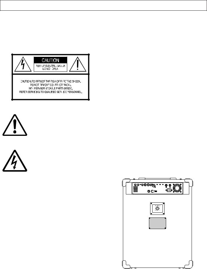
PRODUCT SAFETY MARKINGS:Yamaha electronic products may have either labels similar to the graphics shown below or molded/stamped facsimiles of these graphics on the enclosure. The explanation of these graphics appears on this page. Please observe all cautions indicated on this page and those indicated in the safety instruction section.
See rear of Amplifier for graphic symbol markings.
The exclamation point within the equilateral triangle is intended to alert the user to the presence of important operating and maintenance (servicing) instructions in the literature accompanying the product.
The lightning flash with arrowhead symbol, within the equilateral triangle, is intended to alert the user to the presence of uninsulated “dangerous voltage” within the product’s enclosure that may be of sufficient magnitude to constitute a risk of electrical shock.
IMPORTANT NOTICE: All Yamaha electronic products are tested and approved by an independent safety testing laboratory in order that you may be sure that when it is properly installed and used in its normal and customary manner, all foreseeable risks have been eliminated. DO NOT modify this unit or commission others to do so unless specifically authorized by Yamaha. Product performance and/or safety standards may be diminished. Claims filed under the expressed warranty may be denied if the unit is/has been modified. Implied warranties may also be affected.
SPECIFICATIONS SUBJECT TO CHANGE: The information contained in this manual is believed to be correct at the time of printing. However, Yamaha reserves the right to change or modify any of the specifications without notice or obligation to update existing units.
ENVIRONMENTAL ISSUES: Yamaha strives to produce products that are both user safe and environmentally friendly. We sincerely believe that our products and the production methods used to produce them, meet these goals. In keeping with both the letter and the spirit of the law, we want you to be aware of the following:
Warning: Do not attempt to recharge, disassemble, or incinerate this type of battery. Keep all batteries away from children. Dispose of used batteries promptly and as regulated by applicable laws. Note: In some areas, the servicer is required by law to return the defective parts. However, you do have the option of having the servicer dispose of these parts for you.
Disposal Notice: Should this product become damaged beyond repair, or for some reason its useful life is considered to be at an end, please observe all local, state, and federal regulations that relate to the disposal of products that contain lead, batteries, plastics, etc.
NOTICE: Service charges incurred due to lack of knowledge relating to how a function or effect works (when the unit is operating as designed) are not covered by the manufacturer’s warranty, and are therefore the owners responsibility. Please study this manual carefully and consult your dealer before requesting service.
NAME PLATE LOCATION: The graphic below indicates the location of the name plate. Information such as model number, power requirements, serial number, etc., can be found at this location. You should record the model number, serial number, and the date of purchase in the spaces provided below and retain this manual as a permanent record of your purchase.
|
Model |
|
||
|
Serial No. |
|
||
92-469- (rear) |
Purchase Date |
|
||
4
Precautions
●Avoid using your amplifier and speaker in the following locations to prevent possible damage:
•In direct sunlight or next to heating equipment.
•Extremely cold or hot locations.
•Locations exposed to high humidity or excessive dust.
•Locations subject to strong shocks or vibration.
●Avoid installing this unit where foreign object may fall onto this unit and/or this unit may be exposed to liquid dripping or splashing. On the top of this unit, do not place:
•Other components, as they may cause damage and/or discoloration on the surface of this unit.
•Burning objects (i.e. candles), as they may cause fire, damage to this unit, and/or personal injury.
•Containers with liquid in them, as they may fall and liquid may cause electrical shock to the user and/or damage to this unit.
●If one of the following occurs, disconnect the cable from the INPUT jack as soon as possible then contact the dealer from whom you purchased the device for repair.
•The speaker cable or plug has become damaged.
•Sound is not produced or an abnormal smell or smoke is present.
•A foreign substance gets into the device or liquid is spilled onto the device.
•The device is wet or damp (rain, etc.).
•An abnormality or damage is found on the device.
●Before making any connections, make sure that the power on the amplifier and any external devices is switched OFF.
●To protect the speaker from possible damage, always set the
OUTPUT knob to “0” before switching the power ON/OFF.
●When connecting the speaker jack to a speaker, use only a cable designed specifically for connecting a speaker to the amplifier. The use of any other cable can result in fire.
●Even if the device’s main power switch is switched OFF, power is not cut off from the device. Place the device close to an easily accessible electric outlet so it can be plugged in or unplugged with ease.
●Your Yamaha amplifier is a precision musical instrument. Handle it with care and avoid dropping or bumping it.
●Do not apply excessive force to the switches and controls.
●To prevent damage and possibly electrical shock, never open the case and tamper with the internal circuitry.
●Do not block the ventilation ducts. The device is designed with ducts on the front and back to prevent temperatures from rising inside the device. Blocking the ducts will cause heat to buildup inside the device, which may result in fire.
●Never place the device on an unstable surface, table, or sloped surface. Also, never stack the device excessively. Doing so may cause the device to fall or overturn, causing injury.
*If the device is to be stacked, we recommend that the casters be removed from the amplifier/speaker to prevent overturning.
●During thunderstorms, switch off the power as soon as possible and unplug the device from the electric outlet. If there are lightning strikes, do not touch the power cable if it is still connected to the electric outlet. Doing so can result in electric shock.
●For safety, always remove the power plug from the AC wall outlet if there is any danger of lightning striking in your area.
●Do not use the amplifier for any other purpose than powering a speaker system.
●Keep the amplifier away from neon signs or fluorescent lighting to prevent noise pickup.
●Never use benzene, thinner or other volatile liquids for cleaning, as these chemicals may cause damage or discoloration to the finish. Always use a dry, soft cloth to wipe off dust and dirt.
To protect your speakers
The following may cause damage to speakers:
•Feedback caused when using a microphone.
•Continuous high sound pressure level produced by electronic instruments.
•Continuous high-power output distorted signals.
•Popping noises caused by turning on equipment, or by connecting or disconnecting system-components while the amplifier is turned on.
Operating Cautions!
To use in a safe manner, please obey the following
● About the XLR jack’s polarity
The pin order of the XLR type connector is as follows: 1: Shield (GND), 2: Hot (+), 3: Cold (-)
This conforms to the IEC60268 standard.
● About Cellular Phone Interference
Cellular phones used in close proximity to the device may cause noise. If this is the case, move the phone a little away from the device.
CAUTION!
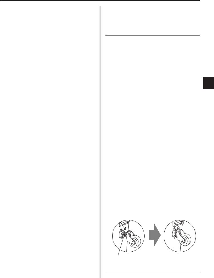
Attaching and removing the casters (BBT500-115 only)
When attaching the supplied casters, make sure that the caster’s shaft is inserted all the way into the receptacle on the bottom of the cabinet. Also, make sure that all four casters are attached to ensure stability.
Using the cabinet with loose or poorly attached casters will result in a condition that is unstable and hazardous, and cause the cabinet to fall over, etc.
Wrong! OK
Insert the shaft until it is no longer visible.
5

Thank you for purchasing the Yamaha BBT500-115/BBT500-110 Bass Amplifier.
The BBT5001-115/BBT500-110 is an all-digital bass amplifier that utilizes Yamaha’s DSP technology to provide bassists with extensive sound tailoring capabilities and simple operation. Thanks to the use of a highly efficient digital power amplifier in combination with Yamaha’s power switching technology, the BBT500-115/BBT500-110 can deliver a maximum 500W of power into 2Ω.
The BBT500-115/BBT500-110 offers bassists precision sound tailoring and control with its 11 sound variation types, 5-band semi-parametric equalizer, compressor, limiter, and noise gate. It is also equipped with a speaker simulator and effects loop for greater tone tailoring and versatility. The BBT500-115/BBT500-110 provides 5 internal memory locations that let you store up to five tone settings for instant recall at the press of a switch. It also offers MIDI compatibility and a bi-amp system (using two amplifiers to create a single system), etc. that make it an excellent choice for use in the studio or live performances.
In order to get the most out of your BBT500-115/BBT500-110 and its sophisticated functions, please thoroughly read this Owner’s Manual before using the device. Also, keep the manual in a safe, convenient place for future reference.
CONTENTS |
|
Panel Controls and Connections ........................................ |
7 |
Front Panel .................................................................................. |
7 |
Rear Panel .................................................................................. |
8 |
Operating Instructions ...................................................... |
11 |
Getting sound output ................................................................. |
11 |
Adjusting the Input Level ........................................................... |
11 |
Sound Setting ........................................................................... |
11 |
Storing and Recalling Patches .................................................. |
12 |
Detailed Parameter Settings ............................................. |
13 |
Amp Mode ................................................................................. |
13 |
Equalizer Mode ......................................................................... |
14 |
Compressor Mode .................................................................... |
14 |
Utility Mode ............................................................................... |
15 |
Air Flow ............................................................................... |
18 |
Error Messages .................................................................. |
18 |
Troubleshooting ................................................................. |
18 |
Specifications ..................................................................... |
19 |
MIDI Implementation Chart ............................................... |
95 |
6
Panel Controls and Connections
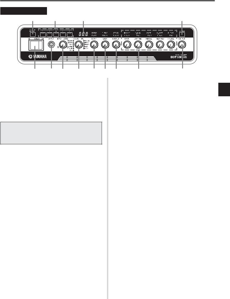
Front Panel
!0 !1 !2
q w e r t y
q Power Switch
This is the unit’s main power switch.
*Always set the OUTPUT volume to “0” before switching the power ON or OFF to protect the speaker from damage.
w Input Jack (INPUT)
This is the unit’s input jack.
Connect the output jack on your bass to this jack.
*Make sure that the power is switched OFF before connecting the bass.
*For U.S. and Canadian models only
To protect against electromagnetic waves, attach the supplied Clamp Filter to the cable connecting the bass guitar to the amplifier. (→ pg. 10)
e Input Level Volume (INPUT LEVEL)
Adjusts the amplifier’s input volume level and the volume of the bass that is connected to the BBT500. Use the indicators located on either side of the knob to check the signal level. (→ pg. 11)
* The INPUT LEVEL setting is not saved in memory.
r Sound Type Select Switch (SOUND TYPE)
Select one of the eleven preset sound variation types.
The indicator of the selected sound type will light. (→ pg. 11)
t Compressor Volume (COMP)
Adjusts the compressor’s compression ratio.
In the Equalizer mode, this knob is used to set the center frequency
(PEQ F) of the 1-band parametric equalizer. (→ pg. 14)
y Gain Volume (GAIN)
Adjusts the pre-amplifier’s gain volume level.
*When this knob is set to “0”, no sound will be produced although the Master Volume is turned up.
In the Equalizer Mode, this knob is used to set the bandwidth (PEQ Q) of the 1-band parametric equalizer. (→ pg. 14)
In the Compressor Mode, this knob is used to set the compressor threshold (THRSLD). (→ pg. 14)
u Master Volume (MASTER)
Adjusts the overall volume of the sound created with the Gain and Tone Control settings. Adjusts the preamplifier’s output level.
* The MASTER volume setting is saved in memory.
In the Equalizer Mode, this knob is used to set the Gain (PEQ G) volume level of the 1-band graphic equalizer. (→ pg. 14)
In the Compressor Mode, this knob is used to adjust the compressor’s attack (ATTACK) time. (→ pg. 14)
!3
u i o
i Tone Controls
(BASS, LOW MID, MIDDLE, HIGH MID, TREBLE)
Adjusts the level of their corresponding frequencies.
In the Equalizer Mode, these knobs are used to set the center frequency (FREQ) for their corresponding tone control. (→ pg. 14)
In the Compressor Mode, these knobs are used to adjust the parameters given below. (→ pg. 14)
BASS ........... |
Compressor’s release (RELEASE) time |
LOW MID ..... |
Compressor’s output gain (C. GAIN) |
MIDDLE ....... |
Compressor’s knee (KNEE) |
HIGH MID .... |
Noise gate threshold (N. GATE) |
TREBLE ....... |
Effect loop blend level (BLEND) |
o Output Volume Level (OUTPUT)
Adjusts the power amplifier’s output level.
This knob is used to set the overall volume level (the amount delivered by the speaker) of the sound created by the pre-amplifier section’s GAIN, MASTER, Tone Controls, etc. Adjusting this volume level has no effect on tone.
*The OUTPUT level setting is not saved in memory.
*This setting does not effect the output level (volume) of the LINE OUT (!8, !9) jacks.
!0Manual Switch (MANUAL)
This switch resets all parameter values (including Equalizer and Compressor mode settings) to the state they were in when the power was switched ON. All knobs function as labeled on the panel, and the setting for each control corresponds to the position of the knob.
If you continuously hold the switch, all settings will be returned to the state that they were in just before the [MANUAL] or Memory switch was pressed (Undo Function). (→ pg. 13)
!1Memory Switches (1-5)
These switches are used to recall data for patches (1-5) saved in the unit’s memory. The selected memory’s (switch’s) indicator lights. (→ pg. 12) After editing patch data, press and hold the switch for about 1 second to save the data to memory. (→ pg. 12)
!2Display
Displays information such as parameter values, etc.
!3Function Switch (FUNCTION)
This switch is used to select the unit’s operating mode.
•Amp Mode (→ pg. 13)
•Equalizer Mode (→ pg. 14)
•Compressor Mode (→ pg. 14)
•Utility Mode (→ pg. 15)
7
 Loading...