


 Loading...
U C A
AX-596
STEREO AMPLIFIER
AMPLIFICATEUR STEREO
OWNER’S MANUAL
MODE D’EMPLOI I
CAUTION
RISK OF ELECTRIC SHOCK
DO NOT OPEN
CAUTION: TO REDUCE THE RISK OF ELECTRIC SHOCK, DO NOT REMOVE
COVER (OR BACK). NO USER-SERVICEABLE PARTS INSIDE. REFER SERVICING TO QUALIFIED SERVICE PERSONNEL.
IMPORTANT
Please record the serial number of this system in the space below.
Model:
Serial No.:
The serial number is located on the rear of the main unit.
Retain this Owner’s Manual in a safe place for future reference.
• Explanation of Graphical Symbols
The lightning flash with arrowhead symbol, within an equilateral triangle, is intended to alert you to the presence of uninsulated “dangerous voltage” within the product’s enclosure that may be of sufficient magnitude to constitute a risk of electric shock to persons.
The exclamation point within an equilateral triangle is intended to alert you to the presence of important operating and maintenance (servicing) instructions in the literature accompanying the appliance.
WARNING
TO REDUCE THE RISK OF FIRE OR ELECTRIC SHOCK, DO NOT EXPOSE THIS APPLIANCE TO RAIN OR MOISTURE.
SAFETY INSTRUCTIONS
1Read Instructions – All the safety and operating instructions should be read before the unit is operated.
2Retain Instructions – The safety and operating instructions should be retained for future reference.
3Heed Warnings – All warnings on the unit and in the operating instructions should be adhered to.
4Follow Instructions – All operating and other instructions should be followed.
5Water and Moisture – The unit should not be used near water – for example, near a bathtub, washbowl, kitchen sink, laundry tub, in a wet basement, or near a swimming pool, etc.
6Carts and Stands – The unit should be used only with a cart or stand that is recommended by the manufacturer.
6A A unit and cart combination should be moved with care. Quick stops, excessive force, and uneven surfaces may cause the unit and cart combination to overturn.
7Wall or Ceiling Mounting – The unit should be mounted to a wall or ceiling only as recommended by the manufacturer.
8Ventilation – The unit should be situated so that its location or position does not interfere with its proper ventilation. For example, the unit should not be situated on a bed, sofa, rug, or similar surface, that may block the ventilation openings; or placed in a builtin installation, such as a bookcase or cabinet that may impede the flow of air through the ventilation openings.
9Heat – The unit should be situated away from heat sources such as radiators, stoves, or other appliances that produce heat.
II
10Power Sources – The unit should be connected to a power supply only of the type described in the operating instructions or as marked on the unit.
11Power-Cord Protection – Power-supply cords should be routed so that they are not likely to be walked on or pinched by items placed upon or against them, paying particular attention to cords at plugs, convenience receptacles, and the point where they exit from the unit.
12Cleaning – The unit should be cleaned only as recommended by the manufacturer.
13Nonuse Periods – The power cord of the unit should be unplugged from the outlet when left unused for a long period of time.
14Object and Liquid Entry – Care should be taken so that objects do not fall into and liquids are not spilled into the inside of the unit.
15Damage Requiring Service – The unit should be serviced by qualified service personnel when:
A.The power-supply cord or the plug has been damaged; or
B.Objects have fallen, or liquid has been spilled into the unit; or
C.The unit has been exposed to rain; or
D.The unit does not appear to operate normally or exhibits a marked change in performance; or
E.The unit has been dropped, or the cabinet damaged.
16Servicing – The user should not attempt to service the unit beyond those means described in the operating instructions. All other servicing should be referred to qualified service personnel.
17Power Lines – An outdoor antenna should be located away from power lines.
18Grounding or Polarization – Precautions should be taken so that the grounding or polarization is not defeated.

FCC INFORMATION (for US customers only)
1. |
IMPORTANT NOTICE : DO NOT MODIFY THIS |
Compliance with FCC regulations does not guarantee that |
|
|
UNIT! |
interference will not occur in all installations. If this |
|
|
This product, when installed as indicated in the |
product is found to be the source of interference, which |
|
|
instructions contained in this manual, meets FCC |
can be determined by turning the unit “OFF” and “ON”, |
|
|
requirements. Modifications not expressly approved |
please try to eliminate the problem by using one of the |
|
|
by Yamaha may void your authority, granted by the |
following measures: |
|
|
FCC, to use the product. |
Relocate either this product or the device that is being |
|
2. |
IMPORTANT : When connecting this product to |
||
affected by the interference. |
|||
|
accessories and/or another product use only high |
||
|
|
||
|
quality shielded cables. Cable/s supplied with this |
Utilize power outlets that are on different branch (circuit |
|
|
product MUST be used. Follow all installation |
breaker or fuse) circuits or install AC line filter/s. |
|
|
instructions. Failure to follow instructions could void |
In the case of radio or TV interference, relocate/reorient |
|
|
your FCC authorization to use this product in the |
||
|
USA. |
the antenna. If the antenna lead-in is 300 ohm ribbon |
|
3. NOTE : This product has been tested and found to |
lead, change the lead-in to coaxial type cable. |
||
|
comply with the requirements listed in FCC |
If these corrective measures do not produce satisfactory |
|
|
Regulations, Part 15 for Class “B” digital devices. |
||
|
results, please contact the local retailer authorized to |
||
|
Compliance with these requirements provides a |
||
|
distribute this type of product. If you can not locate the |
||
|
reasonable level of assurance that your use of this |
||
|
appropriate retailer, please contact Yamaha Electronics |
||
|
product in a residential environment will not result in |
||
|
Corp., U.S.A. 6660 Orangethorpe Ave, Buena Park, CA |
||
|
harmful interference with other electronic devices. |
||
|
90620. |
||
|
|
||
|
This equipment generates/uses radio frequencies |
The above statements apply ONLY to those products |
|
|
and, if not installed and used according to the |
distributed by Yamaha Corporation of America or its |
|
|
instructions found in the users manual, may cause |
subsidiaries. |
|
|
interference harmful to the operation of other |
|
|
|
electronic devices. |
|
|
We Want You Listening For A Lifetime
YAMAHA and the Electronic Industries Association’s
Consumer Electronics Group want you to get the most out of your equipment by playing it at a safe level. One that lets the sound come through loud and clear without annoying blaring or distortion – and, most importantly, without affecting your sensitive hearing.
Since hearing damage from loud sounds is often undetectable until it is too late, YAMAHA and the Electronic Industries Association’s
Consumer Electronics Group recommend you to avoid prolonged exposure from excessive volume levels.
III
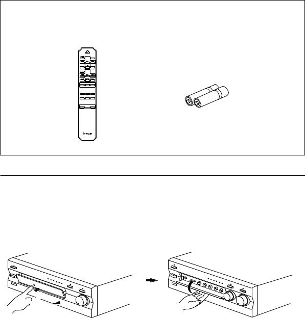
UNPACKING DEBALLAGE
After unpacking, check that the following items are contained.
Après le déballage, vérifier que les pièces suivantes sont incluses.
●Remote control
●Télécommande
|
STANDBY/ON |
|
DECK A/B |
|
TAPE |
DIR A |
DIR B |
DISC SKIP |
|
|
CD |
●Batteries (size AA, R6, UM-3)
●Piles (format AA, R6, UM-3)
–PRESET + A/B/C/D/E
TUNER
MD TAPE CD/DVD
AUX PHONO TUNER
–VOLUME +
Opening and closing the front cover
Close the front cover whenever the controls inside the panel are not used.
Ouverture et fermeture du couvercle avant
Fermer le couvercle avant lorsque les commandes placées à l’intérieur du panneau ne sont pas utilisées.
To open the front cover |
To close the front cover |
Pour ouvrir le couvercle avant |
Pour fermer le couvercle avant |
 1
1 


 2
2
IV

Thank you for selecting this YAMAHA stereo amplifier.
FEATURES
v100W + 100W (8Ω) RMS Output Power, 0.015% THD, 20–20,000 Hz
vHighly Dynamic Power, Low Impedance Drive Capability
vContinuously Variable LOUDNESS Control
vCD/DVD DIRECT AMP Switch Used to Reproduce the Purest CD and DVD Sound
vPURE DIRECT Switch Used to Reproduce the Purest Source Sound
vREC OUT Selector Independent of Input Source Selection
vPRE OUT/MAIN IN Terminals for Connecting An Equalizer, Surround-Sound Processor, etc.
vRemote Control Capability
CONTENTS |
|
SAFETY INSTRUCTIONS ....................................................................................... |
II |
UNPACKING ........................................................................................................... |
IV |
FEATURES ............................................................................................................... |
1 |
CAUTION ................................................................................................................... |
2 |
NOTES ABOUT THE REMOTE CONTROL .............................................................. |
3 |
CONTROLS AND THEIR FUNCTIONS .................................................................... |
4 |
CONNECTIONS ........................................................................................................ |
7 |
OPERATION ........................................................................................................... |
10 |
TROUBLESHOOTING ............................................................................................ |
13 |
SPECIFICATIONS ................................................................................................... |
14 |
English
E-1
CAUTION: Read this before operating your unit.
1. To assure the finest performance, please read this |
13. Do not connect any audio equipment to the AC outlet |
||
|
manual carefully. Keep it in a safe place for future |
on the rear panel if the equipment requires more power |
|
|
reference. |
than the outlet is rated to provide. |
|
2. Install this unit in a cool, dry, clean place – away from |
14. VOLTAGE SELECTOR |
||
|
windows, heat sources, sources of excessive vibration, |
(China and General models only) |
|
|
dust, moisture and cold. Avoid sources of humming |
The voltage selector on the rear panel of this unit |
|
|
(transformers, motors). To prevent fire or electrical |
must be set for your local main voltage BEFORE |
|
|
shock, do not expose the unit to rain or water. |
plugging into the AC main supply. |
|
3. |
Never open the cabinet. If something drops into the |
Voltages are 110/120/220/240 V AC, 50/60 Hz. |
|
|
set, contact your dealer. |
|
|
|
When this unit is turned off by pressing the STANDBY/ON |
||
4. Do not use force on switches, controls or connection |
|||
switch on the front panel or the remote control, the |
|||
|
wires. When moving the unit, first disconnect the |
STANDBY indicator on the front panel lights up. This state |
|
|
power plug and the wires connected to other |
is called the standby mode. In this mode, this unit is |
|
|
equipments. Never pull the wires themselves. |
designed to consume a small amount of power. This |
|
5. |
The openings on the unit cover assure proper |
unit’s power supply is completely cut off from the AC line |
|
|
ventilation of the unit. If these openings are |
only when the POWER switch on the front panel is set in |
|
|
the OFF position or the AC power cord is disconnected. |
||
|
obstructed, the temperature inside the unit will rise |
||
|
|
||
|
rapidly; therefore, avoid placing objects against these |
|
|
|
openings. Install the unit in a well-ventilated area to |
For Canadian Customers |
|
|
prevent fire or damage. |
To prevent electric shock, match wide blade of plug to |
|
|
<Europe, U.K. and China models only> |
wide slot and fully insert. |
|
|
Be sure to allow a space of at least 20 cm behind, 20 |
This Class B digital apparatus complies with Canadian |
|
|
cm on both sides and 30 cm above the top panel of the |
||
|
ICES-003. |
||
|
unit to prevent fire or damage. |
||
|
|
||
6.The voltage used must be the same as that specified
on this unit. Using this unit with a higher voltage than |
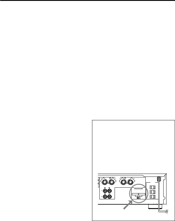
WARNING |
|
|
||
specified is dangerous and may result in fire or other |
Do not change the IMPEDANCE SELECTOR switch |
|
accidents. YAMAHA will not be held responsible for |
setting while the power to this unit is on, otherwise |
|
any damage resulting from use of this unit with a |
this unit may be damaged. |
|
voltage other than specified. |
If this unit fails to turn on when the POWER switch is |
|
7. Always set the VOLUME control to “∞” before starting |
||
pressed: |
||
the audio source play. Increase the volume gradually |
The IMPEDANCE SELECTOR switch may not be set to |
|
to an appropriate level after the play has been started. |
either end. If so, set the switch to either end when this |
|
8. Do not attempt to clean the unit with chemical solvents |
unit’s power supply is completely cut off. |
|
as this might damage the finish. Use a clean, dry |
(U.S.A. model) |
|
cloth. |
||
|
9. |
Be sure to read the “TROUBLESHOOTING” section |
|
SPEAKERS |
|
|
|
R |
L |
|
||
|
|
|
A |
|
MAINS |
|
regarding common operating errors before concluding |
|
|
|
l00W MAX. TOTAL |
|
|
|
|
|
AC OUTLETS |
|
|
|
|
|
SWITCHED |
|
|
|
|
|
I20V 60Hz |
|
that the unit is faulty. |
|
CAUTION SEE INSTRUCTION MANUAL FOR CORRECT SETTING. |
|
|
|
|
|
SET BEFORE POWER ON |
||
|
|
R |
L |
IMPEDANCE SELECTOR |
|
10. |
When not planning to use this unit for a long period |
B |
|
A OR B : 4ΩMIN. /SPEAKER |
A OR B : 6ΩMIN. /SPEAKER |
|
|
|
|
A B : 8ΩMIN. /SPEAKER |
A B : I2ΩMIN. /SPEAKER |
|
(ie., vacation, etc.), disconnect the AC power plug from |
|
|
|
|
|
the wall outlet. |
|
|
|
|
11. To prevent lightning damage, disconnect the AC power |
|
plug when there is an electric storm. |
IMPEDANCE SELECTOR |
12.Grounding or polarization – Precautions should be taken so that the grounding or polarization of an appliance is not defeated.
E-2
NOTES ABOUT THE REMOTE CONTROL
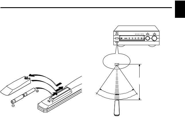
Battery installation |
Remote control operation range |
Since the remote control will be used for many of this unit’s control operations, you should begin by installing the supplied batteries.
1.Turn the remote control over and remove the battery compartment cover by sliding it in the direction of the arrow.
2.Insert the batteries (AA, R6, UM-3 type) according to the polarity markings on the inside of the battery compartment.
3.Close the battery compartment cover.
Remote control sensor
1 |
|
|
3 |
|
Within approximately |
|
6 m (19.7 feet) |
|
|
|
|
2 |
30° |
° |
30 |
English
Battery replacement
If you notice that the remote control must be used closer to the main unit, the batteries are weak. Replace both batteries with new ones.
Notes
cUse AA, R6, UM-3 batteries.
cBe sure the polarities are correct. (See the illustration inside the battery compartment.)
cRemove the batteries if the remote control is not used for an extended period of time.
cIf batteries leak, dispose of them immediately. Avoid touching the leaked material and contact with clothing, etc. Clean the battery compartment thoroughly before installing new batteries.
Notes
cThe area between the remote control and the main unit must be clear of large obstacles.
cDo not expose the remote control sensor to strong lighting, in particular, an inverter type fluorescent lamp; otherwise, the remote control may not work properly. If necessary, position the main unit away from direct lighting.
E-3

CONTROLS AND THEIR FUNCTIONS
FRONT PANEL
1 2 3 |
4 |
5 |
6 |
|
NATURAL SOUND STEREO AMPLIFIER AX–596 |
|
|
|
|
STANDBY |
AUX |
MD |
TAPE CD/DVD TUNER PHONO |
PURE DIRECT |
CD/DVD DIRECT AMP |
|
POWER |
ON  OFF
OFF 
|
|
|
|
|
|
|
|
|
|
|
|
|
|
|
|
|
INPUT |
VOLUME |
|
|
|
|
|
|
|
|
|
|
|
|
|
|
|
|
|
|
l6 |
|
|
|
|
|
|
|
|
|
|
|
|
|
|
|
|
|
20 |
l2 |
PHONES |
SPEAKERS |
|
BASS |
TREBLE |
BALANCE |
LOUDNESS |
REC OUT |
8 |
||||||||||
|
|
|
|
|
|
|
|
|
|
|
|
|
|
|
|
|
28 |
|
|
A |
B |
|
l |
0 |
l |
l |
0 |
l |
l |
0 |
l |
l |
FLAT |
—30dB |
TAPE CD/DVD TUNER |
|
|
|
|
|
2 |
|
|
2 |
2 |
|
2 |
2 |
|
2 |
2 |
|
I0 |
MD |
PHONO |
|
STANDBY/ON |
|
|
3 |
|
|
3 |
3 |
|
3 |
3 |
|
3 |
3 |
|
9 |
AUX |
40 |
4 |
|
ON |
OFF |
4 |
|
|
4 |
4 |
|
4 |
4 |
|
4 |
4 |
|
8 |
|
|
|
|
|
5 |
|
5 |
5 |
|
5 |
L 5 |
|
5 R |
5 |
|
7 |
|
|
|
||
|
|
|
|
|
|
|
6 |
|
|
|
||||||||
|
|
|
|
|
|
|
|
|
|
|
|
|
|
|
|
|
|
|
|
|
|
|
|
|
|
|
|
|
|
|
|
|
|
|
|
60 |
2 |
|
|
|
|
|
|
|
|
|
|
|
|
|
|
|
|
|
|
0 |
|
|
|
|
|
|
|
|
|
|
|
|
|
|
|
|
|
|
–dB |
7 8 9 0 A B C D E |
F |
1POWER
Press this switch inward (ON) to use this unit. In this state, you can turn on this unit or turn this unit in the standby mode by pressing STANDBY/ON. Press this switch to release it outward (OFF) to completely cut off this unit’s power supply from the AC line.
2STANDBY indicator
Lights up only while this unit is in the standby mode.
3STANDBY/ON
Press this switch to turn on the power. Press again to set this unit in the standby mode.
*This switch can be used only when POWER is set in the ON position.
Standby mode
This unit is still using a small amount of power in this mode in order to be ready to receive infrared-signals from the remote control.
4Input source indicators
The indicator of the currently selected input source lights up.
5PURE DIRECT and indicator
Press this switch, and the indicator above it lights up.
You can listen to a source in the purest sound with this function. (Refer to page 12 for details.)
Press this switch again to cancel this function.
6CD/DVD DIRECT AMP and indicator
Press this switch, and the indicator above it lights up. You can listen to a CD or DVD source in the purest sound with this function. (Refer to page 12 for details.) Press this switch again to cancel this function.
7Remote control sensor
Receives signals from the remote control.
E-4

8PHONES jack
When you listen with headphones, connect the headphones to the PHONES jack and set both SPEAKERS A and B switches to the OFF position.
PHONES
PHONES
9SPEAKERS
Press the switch A or B (or both) inward (ON) for the speakers you will use. Press and release the switch outward (OFF) for the speakers you do not use.
0Tone controls BASS
Rotate this knob to increase or decrease the low frequency response. The 0 position produces a flat response.
TREBLE
Rotate this knob to increase or decrease the high frequency response. The 0 position produces a flat response.
English
ABALANCE
The balance of the output volume to the left and right speakers can be adjusted to compensate for sound imbalances caused by the speaker location or listening room conditions.
BLOUDNESS
Used to compensate for the human ears’ loss of sensitivity to high and low-frequency ranges at low volume. (Refer to page 12 for details.)
CREC OUT selector
Rotate this knob to select the source for recording to an MD recorder or tape deck. This setting is independent of the INPUT selector setting, so this function allows you to record the selected source while listening to another source.
DFront cover
Refer to inside of the front cover on how to open and close the front cover.
EINPUT selector
Turn this knob to select the input source.
The selected source will be shown by the lighting of corresponding input source indicator.
FVOLUME
Turn this knob to raise or lower the volume level. (The
REC OUT level is not affected.)
E-5

REMOTE CONTROL
The remote control is designed to control the most commonly used functions of the main unit. If you have a YAMAHA CD player, tuner, tape deck, etc. with remote control compatibility, this remote control will also control their various functions.
|
|
For Control of This Unit |
|
|
1 STANDBY/ON |
1 |
STANDBY/ON |
Press this key to turn on this unit or turn it into the |
|
standby mode. |
|
|
|
|
|
|
This key can be used only when the POWER switch on |
|
DECK A/B |
the main unit is set in the ON position. |
|
TAPE |
|
|
1 |
Standby mode |
|
In this state, this unit consumes a very small |
|
|
|
|
DIR A |
DIR B |
quantity of power to receive infrared-signals from |
|
|
the remote control. |
DISC SKIP |
|
|
|
CD |
2 Input selector keys |
|
|
|
|
2 |
Press a key to select the input source. |
|
|
3 VOLUME +/– |
|
|
Press these keys to increase or decrease the volume. |
– PRESET + |
A/B/C/D/E |
3 |
|
|
TUNER |
|
|
|
|
For Control of Other Components |
|
|
|
|
|
MD |
TAPE |
CD/DVD |
Note |
2 |
|
|
The functions of the keys to control other YAMAHA |
|
|
components are the same as the corresponding keys on |
|
AUX |
PHONO |
TUNER |
|
|
|
|
those components. Refer to those components’ |
|
|
|
instruction manuals for details. |
3 |
– VOLUME + |
1 |
|
|
2
Tape deck keys
These keys control tape decks.
*DIR A, B and A/B apply only to double cassette tape decks.
*Pressing DIR A will reverse the tape direction on a single cassette tape deck with the automatic reverse function.
CD player keys
These keys control compact disc players.
* DISC SKIP is used for disc changers only.
3Tuner keys
These keys control tuners.
PRESET +: Press this key to select the next preset station number.
PRESET –: Press this key to select the previous preset station number.
A/B/C/D/E: Press this key to select the group (A – E) of preset station numbers.
E-6
Loading...